EP2721087B1 - Regioregular pyridal[2,1,3]thiadiazole pi-conjugated copolymers for organic semiconductors - Google Patents
Regioregular pyridal[2,1,3]thiadiazole pi-conjugated copolymers for organic semiconductors Download PDFInfo
- Publication number
- EP2721087B1 EP2721087B1 EP12801086.5A EP12801086A EP2721087B1 EP 2721087 B1 EP2721087 B1 EP 2721087B1 EP 12801086 A EP12801086 A EP 12801086A EP 2721087 B1 EP2721087 B1 EP 2721087B1
- Authority
- EP
- European Patent Office
- Prior art keywords
- substituted
- integer
- dithiophene
- monomer
- regioregular
- Prior art date
- Legal status (The legal status is an assumption and is not a legal conclusion. Google has not performed a legal analysis and makes no representation as to the accuracy of the status listed.)
- Active
Links
- 0 CC(*)=C[C@@]1*CCC1 Chemical compound CC(*)=C[C@@]1*CCC1 0.000 description 7
- OZBIHQANVLVZBE-UHFFFAOYSA-O Cc1cc([sH+]c2c3[s]c(C)c2)c3[s]1 Chemical compound Cc1cc([sH+]c2c3[s]c(C)c2)c3[s]1 OZBIHQANVLVZBE-UHFFFAOYSA-O 0.000 description 1
Images


Classifications
-
- H—ELECTRICITY
- H10—SEMICONDUCTOR DEVICES; ELECTRIC SOLID-STATE DEVICES NOT OTHERWISE PROVIDED FOR
- H10K—ORGANIC ELECTRIC SOLID-STATE DEVICES
- H10K85/00—Organic materials used in the body or electrodes of devices covered by this subclass
- H10K85/10—Organic polymers or oligomers
- H10K85/111—Organic polymers or oligomers comprising aromatic, heteroaromatic, or aryl chains, e.g. polyaniline, polyphenylene or polyphenylene vinylene
- H10K85/113—Heteroaromatic compounds comprising sulfur or selene, e.g. polythiophene
-
- C—CHEMISTRY; METALLURGY
- C08—ORGANIC MACROMOLECULAR COMPOUNDS; THEIR PREPARATION OR CHEMICAL WORKING-UP; COMPOSITIONS BASED THEREON
- C08G—MACROMOLECULAR COMPOUNDS OBTAINED OTHERWISE THAN BY REACTIONS ONLY INVOLVING UNSATURATED CARBON-TO-CARBON BONDS
- C08G61/00—Macromolecular compounds obtained by reactions forming a carbon-to-carbon link in the main chain of the macromolecule
- C08G61/12—Macromolecular compounds containing atoms other than carbon in the main chain of the macromolecule
- C08G61/122—Macromolecular compounds containing atoms other than carbon in the main chain of the macromolecule derived from five- or six-membered heterocyclic compounds, other than imides
- C08G61/123—Macromolecular compounds containing atoms other than carbon in the main chain of the macromolecule derived from five- or six-membered heterocyclic compounds, other than imides derived from five-membered heterocyclic compounds
- C08G61/126—Macromolecular compounds containing atoms other than carbon in the main chain of the macromolecule derived from five- or six-membered heterocyclic compounds, other than imides derived from five-membered heterocyclic compounds with a five-membered ring containing one sulfur atom in the ring
-
- H—ELECTRICITY
- H10—SEMICONDUCTOR DEVICES; ELECTRIC SOLID-STATE DEVICES NOT OTHERWISE PROVIDED FOR
- H10K—ORGANIC ELECTRIC SOLID-STATE DEVICES
- H10K85/00—Organic materials used in the body or electrodes of devices covered by this subclass
- H10K85/10—Organic polymers or oligomers
- H10K85/151—Copolymers
-
- C—CHEMISTRY; METALLURGY
- C08—ORGANIC MACROMOLECULAR COMPOUNDS; THEIR PREPARATION OR CHEMICAL WORKING-UP; COMPOSITIONS BASED THEREON
- C08G—MACROMOLECULAR COMPOUNDS OBTAINED OTHERWISE THAN BY REACTIONS ONLY INVOLVING UNSATURATED CARBON-TO-CARBON BONDS
- C08G2261/00—Macromolecular compounds obtained by reactions forming a carbon-to-carbon link in the main chain of the macromolecule
- C08G2261/10—Definition of the polymer structure
- C08G2261/12—Copolymers
- C08G2261/124—Copolymers alternating
-
- C—CHEMISTRY; METALLURGY
- C08—ORGANIC MACROMOLECULAR COMPOUNDS; THEIR PREPARATION OR CHEMICAL WORKING-UP; COMPOSITIONS BASED THEREON
- C08G—MACROMOLECULAR COMPOUNDS OBTAINED OTHERWISE THAN BY REACTIONS ONLY INVOLVING UNSATURATED CARBON-TO-CARBON BONDS
- C08G2261/00—Macromolecular compounds obtained by reactions forming a carbon-to-carbon link in the main chain of the macromolecule
- C08G2261/10—Definition of the polymer structure
- C08G2261/14—Side-groups
- C08G2261/141—Side-chains having aliphatic units
- C08G2261/1412—Saturated aliphatic units
-
- C—CHEMISTRY; METALLURGY
- C08—ORGANIC MACROMOLECULAR COMPOUNDS; THEIR PREPARATION OR CHEMICAL WORKING-UP; COMPOSITIONS BASED THEREON
- C08G—MACROMOLECULAR COMPOUNDS OBTAINED OTHERWISE THAN BY REACTIONS ONLY INVOLVING UNSATURATED CARBON-TO-CARBON BONDS
- C08G2261/00—Macromolecular compounds obtained by reactions forming a carbon-to-carbon link in the main chain of the macromolecule
- C08G2261/10—Definition of the polymer structure
- C08G2261/14—Side-groups
- C08G2261/148—Side-chains having aromatic units
-
- C—CHEMISTRY; METALLURGY
- C08—ORGANIC MACROMOLECULAR COMPOUNDS; THEIR PREPARATION OR CHEMICAL WORKING-UP; COMPOSITIONS BASED THEREON
- C08G—MACROMOLECULAR COMPOUNDS OBTAINED OTHERWISE THAN BY REACTIONS ONLY INVOLVING UNSATURATED CARBON-TO-CARBON BONDS
- C08G2261/00—Macromolecular compounds obtained by reactions forming a carbon-to-carbon link in the main chain of the macromolecule
- C08G2261/10—Definition of the polymer structure
- C08G2261/16—End groups
- C08G2261/164—End groups comprising organic end groups
- C08G2261/1646—End groups comprising organic end groups comprising aromatic or heteroaromatic end groups
-
- C—CHEMISTRY; METALLURGY
- C08—ORGANIC MACROMOLECULAR COMPOUNDS; THEIR PREPARATION OR CHEMICAL WORKING-UP; COMPOSITIONS BASED THEREON
- C08G—MACROMOLECULAR COMPOUNDS OBTAINED OTHERWISE THAN BY REACTIONS ONLY INVOLVING UNSATURATED CARBON-TO-CARBON BONDS
- C08G2261/00—Macromolecular compounds obtained by reactions forming a carbon-to-carbon link in the main chain of the macromolecule
- C08G2261/10—Definition of the polymer structure
- C08G2261/21—Stereochemical aspects
- C08G2261/212—Regioregularity
-
- C—CHEMISTRY; METALLURGY
- C08—ORGANIC MACROMOLECULAR COMPOUNDS; THEIR PREPARATION OR CHEMICAL WORKING-UP; COMPOSITIONS BASED THEREON
- C08G—MACROMOLECULAR COMPOUNDS OBTAINED OTHERWISE THAN BY REACTIONS ONLY INVOLVING UNSATURATED CARBON-TO-CARBON BONDS
- C08G2261/00—Macromolecular compounds obtained by reactions forming a carbon-to-carbon link in the main chain of the macromolecule
- C08G2261/30—Monomer units or repeat units incorporating structural elements in the main chain
- C08G2261/32—Monomer units or repeat units incorporating structural elements in the main chain incorporating heteroaromatic structural elements in the main chain
- C08G2261/324—Monomer units or repeat units incorporating structural elements in the main chain incorporating heteroaromatic structural elements in the main chain condensed
- C08G2261/3241—Monomer units or repeat units incorporating structural elements in the main chain incorporating heteroaromatic structural elements in the main chain condensed containing one or more nitrogen atoms as the only heteroatom, e.g. carbazole
-
- C—CHEMISTRY; METALLURGY
- C08—ORGANIC MACROMOLECULAR COMPOUNDS; THEIR PREPARATION OR CHEMICAL WORKING-UP; COMPOSITIONS BASED THEREON
- C08G—MACROMOLECULAR COMPOUNDS OBTAINED OTHERWISE THAN BY REACTIONS ONLY INVOLVING UNSATURATED CARBON-TO-CARBON BONDS
- C08G2261/00—Macromolecular compounds obtained by reactions forming a carbon-to-carbon link in the main chain of the macromolecule
- C08G2261/30—Monomer units or repeat units incorporating structural elements in the main chain
- C08G2261/32—Monomer units or repeat units incorporating structural elements in the main chain incorporating heteroaromatic structural elements in the main chain
- C08G2261/324—Monomer units or repeat units incorporating structural elements in the main chain incorporating heteroaromatic structural elements in the main chain condensed
- C08G2261/3246—Monomer units or repeat units incorporating structural elements in the main chain incorporating heteroaromatic structural elements in the main chain condensed containing nitrogen and sulfur as heteroatoms
-
- C—CHEMISTRY; METALLURGY
- C08—ORGANIC MACROMOLECULAR COMPOUNDS; THEIR PREPARATION OR CHEMICAL WORKING-UP; COMPOSITIONS BASED THEREON
- C08G—MACROMOLECULAR COMPOUNDS OBTAINED OTHERWISE THAN BY REACTIONS ONLY INVOLVING UNSATURATED CARBON-TO-CARBON BONDS
- C08G2261/00—Macromolecular compounds obtained by reactions forming a carbon-to-carbon link in the main chain of the macromolecule
- C08G2261/30—Monomer units or repeat units incorporating structural elements in the main chain
- C08G2261/34—Monomer units or repeat units incorporating structural elements in the main chain incorporating partially-aromatic structural elements in the main chain
- C08G2261/344—Monomer units or repeat units incorporating structural elements in the main chain incorporating partially-aromatic structural elements in the main chain containing heteroatoms
-
- C—CHEMISTRY; METALLURGY
- C08—ORGANIC MACROMOLECULAR COMPOUNDS; THEIR PREPARATION OR CHEMICAL WORKING-UP; COMPOSITIONS BASED THEREON
- C08G—MACROMOLECULAR COMPOUNDS OBTAINED OTHERWISE THAN BY REACTIONS ONLY INVOLVING UNSATURATED CARBON-TO-CARBON BONDS
- C08G2261/00—Macromolecular compounds obtained by reactions forming a carbon-to-carbon link in the main chain of the macromolecule
- C08G2261/40—Polymerisation processes
- C08G2261/41—Organometallic coupling reactions
- C08G2261/414—Stille reactions
-
- C—CHEMISTRY; METALLURGY
- C08—ORGANIC MACROMOLECULAR COMPOUNDS; THEIR PREPARATION OR CHEMICAL WORKING-UP; COMPOSITIONS BASED THEREON
- C08G—MACROMOLECULAR COMPOUNDS OBTAINED OTHERWISE THAN BY REACTIONS ONLY INVOLVING UNSATURATED CARBON-TO-CARBON BONDS
- C08G2261/00—Macromolecular compounds obtained by reactions forming a carbon-to-carbon link in the main chain of the macromolecule
- C08G2261/90—Applications
- C08G2261/91—Photovoltaic applications
-
- C—CHEMISTRY; METALLURGY
- C08—ORGANIC MACROMOLECULAR COMPOUNDS; THEIR PREPARATION OR CHEMICAL WORKING-UP; COMPOSITIONS BASED THEREON
- C08G—MACROMOLECULAR COMPOUNDS OBTAINED OTHERWISE THAN BY REACTIONS ONLY INVOLVING UNSATURATED CARBON-TO-CARBON BONDS
- C08G2261/00—Macromolecular compounds obtained by reactions forming a carbon-to-carbon link in the main chain of the macromolecule
- C08G2261/90—Applications
- C08G2261/92—TFT applications
-
- H—ELECTRICITY
- H10—SEMICONDUCTOR DEVICES; ELECTRIC SOLID-STATE DEVICES NOT OTHERWISE PROVIDED FOR
- H10K—ORGANIC ELECTRIC SOLID-STATE DEVICES
- H10K10/00—Organic devices specially adapted for rectifying, amplifying, oscillating or switching; Organic capacitors or resistors having a potential-jump barrier or a surface barrier
- H10K10/40—Organic transistors
- H10K10/46—Field-effect transistors, e.g. organic thin-film transistors [OTFT]
- H10K10/462—Insulated gate field-effect transistors [IGFETs]
- H10K10/466—Lateral bottom-gate IGFETs comprising only a single gate
-
- H—ELECTRICITY
- H10—SEMICONDUCTOR DEVICES; ELECTRIC SOLID-STATE DEVICES NOT OTHERWISE PROVIDED FOR
- H10K—ORGANIC ELECTRIC SOLID-STATE DEVICES
- H10K10/00—Organic devices specially adapted for rectifying, amplifying, oscillating or switching; Organic capacitors or resistors having a potential-jump barrier or a surface barrier
- H10K10/40—Organic transistors
- H10K10/46—Field-effect transistors, e.g. organic thin-film transistors [OTFT]
- H10K10/462—Insulated gate field-effect transistors [IGFETs]
- H10K10/468—Insulated gate field-effect transistors [IGFETs] characterised by the gate dielectrics
- H10K10/474—Insulated gate field-effect transistors [IGFETs] characterised by the gate dielectrics the gate dielectric comprising a multilayered structure
- H10K10/476—Insulated gate field-effect transistors [IGFETs] characterised by the gate dielectrics the gate dielectric comprising a multilayered structure comprising at least one organic layer and at least one inorganic layer
-
- H—ELECTRICITY
- H10—SEMICONDUCTOR DEVICES; ELECTRIC SOLID-STATE DEVICES NOT OTHERWISE PROVIDED FOR
- H10K—ORGANIC ELECTRIC SOLID-STATE DEVICES
- H10K85/00—Organic materials used in the body or electrodes of devices covered by this subclass
- H10K85/40—Organosilicon compounds, e.g. TIPS pentacene
-
- Y—GENERAL TAGGING OF NEW TECHNOLOGICAL DEVELOPMENTS; GENERAL TAGGING OF CROSS-SECTIONAL TECHNOLOGIES SPANNING OVER SEVERAL SECTIONS OF THE IPC; TECHNICAL SUBJECTS COVERED BY FORMER USPC CROSS-REFERENCE ART COLLECTIONS [XRACs] AND DIGESTS
- Y02—TECHNOLOGIES OR APPLICATIONS FOR MITIGATION OR ADAPTATION AGAINST CLIMATE CHANGE
- Y02E—REDUCTION OF GREENHOUSE GAS [GHG] EMISSIONS, RELATED TO ENERGY GENERATION, TRANSMISSION OR DISTRIBUTION
- Y02E10/00—Energy generation through renewable energy sources
- Y02E10/50—Photovoltaic [PV] energy
- Y02E10/549—Organic PV cells
Definitions
- the invention relates to conjugated polymers and methods of making the same.
- Organic ⁇ -conjugated polymers are attractive materials for use in the active layer, as they combine good absorption and emission characteristics with efficient charge carrier mobility and have the ability to be solution processed onto flexible substrates.
- OFET organic field effect transistors
- OCV organic photovoltaic
- regioregularity can have a great impact on the properties of polymers [7].
- enhanced regioregularity of poly(3-alkylthiophene) can impart to polymers a higher crystallinity, red-shifted optical absorption, higher conductivity, and smaller band-gap [8].
- the inventors have surmised that for a polymer based on an asymmetric PT unit, a regioregular backbone structure with more effective electron localization can result in a higher charge carrier mobility and enhanced photovoltaic performance.
- a regioregular donor-acceptor copolymer comprising a regioregular conjugated main chain section, said regioregular conjugated main chain section having a repeat unit that comprises a pyridine of the structure wherein Ar is a substituted or non-substituted aromatic functional group; and the pyridine is regioregularly arranged along the conjugated main chain section; and wherein the repeat unit further comprises a dithiophene of the structure wherein each Ar is independently a substituted or non-substituted aromatic functional group, or each Ar is independently nothing and the valence of its respective thiophene ring is completed with hydrogen; each R is independently hydrogen or a substituted or non-substituted alkyl, aryl or alkoxy chain; and X is C, Si, Ge, N or P.
- a method of preparing the regioregular donor-acceptor copolymer of the invention comprising: regioselectively preparing a monomer; and reacting the monomer to produce said donor-acceptor copolymer, wherein the regioselectivity of preparing the monomer is 95% or greater.
- an electronic device that includes the regioregular polymer.
- the regioregular polymer includes a regioregular conjugated main chain section having a repeat unit that includes a pyridine of the structure where a) Ar is a substituted or non-substituted aromatic functional group, and b) the pyridine is regioregularly arranged along the conjugated main chain section.
- the regioregularity of the main chain section can be 95% or greater, and the charge carrier mobility of the regioregular polymer can be greater than the charge carrier mobility of a regiorandom polymer of similar composition.
- the repeat unit of the regioregular polymer further includes a dithiophene of the structure where a) each Ar is independently a substituted or non-substituted aromatic functional group, or each Ar is independently nothing and the valence of its respective thiophene ring is completed with hydrogen, b) each R is independently hydrogen or a substituted or non-substituted alkyl, aryl or alkoxy chain, and c) X is C, Si, Ge, N or P.
- each substituted or non-substituted aromatic functional group of the pyridine and the dithiophene independently includes one or more alkyl or aryl chains.
- X of the dithiophene can be C or Si.
- the pyridine is a pyridine unit of Table 1 (which is described below).
- the repeat unit further includes a dithiophene unit of Table 2 (which is described below).
- the pyridine unit is and the dithiophene unit is wherein each R is independently hydrogen or a substituted or non-substituted alkyl, aryl or alkoxy chain.
- the repeat unit includes or where each R is independently hydrogen or a substituted or non-substituted alkyl, aryl or alkoxy chain, and X is C, Si, Ge, N or P.
- a device including any regioregular polymer described herein is provided.
- the device can be, but is not limited to, a field effect transistor, organic photovoltaic device, polymer light emitting diode, organic light emitting diode, organic photodetector, or biosensor.
- the regioregular polymer can form an active semiconducting layer.
- regioregular in relation to a polymer or a section of a polymer means the non-random orientation or arrangement of the pyridal-N along the polymer backbone.
- the nitrogen atom of the pyridine faces in the same direction in all or a majority of the repeat units of the polymer or polymer section.
- the pyridal nitrogen atom of the PT unit faces the CDT unit.
- all or a majority of the PT units in the copolymers of Scheme 1 adopted a head-to-tail arrangement next to each other.
- all or a majority of the repeat units of the polymer or polymer section have two pyridine units, with the nitrogen atoms of the pyridine units oriented toward each other.
- the pyridal nitrogen atom of one PT unit is oriented towards the pyridal nitrogen atom of the other PT unit, which is a head-to-head connection through the CDT unit.
- a monomer is regioselectively prepared.
- the monomer is prepared by reacting halogen-functionalized PT with organotin-functionalized cyclopenta[2,1- b :3,4- b ']dithiophene.
- the reaction can be carried out at a temperature in the range of about 50 °C to about 150 °C.
- the monomer is prepared by reacting halogen-functionalized PT with organotin-functionalized indaceno[1,2- b :5,6- b ']dithiophene (IDT), where the reaction can be carried out at a temperature in the range of about 50 °C to about 150 °C.
- IDT organotin-functionalized indaceno[1,2- b :5,6- b ']dithiophene
- the monomer is prepared by reacting halogen-functionalized PT with organoboron-functionalized cyclopenta[2,1- b :3,4- b ']dithiophene or organboron-functionalized indaceno[1,2- b :5,6- b ']dithiophene (IDT), where the reaction can be carried out at a temperature in the range of about 50 °C to about 150 °C.
- the monomer is prepared by reacting halogen-functionalized PT with cyclopenta[2,1- b :3,4- b ']dithiophene or indaceno[1,2- b :5,6- b ']dithiophene (IDT) by direct arylation polyerization, in which direct arylation allows the formation of carbon-carbon bonds between aromatic units having activated hydrogen atoms without the use of organometallic intermediates, where the reaction can be carried out at a temperature in the range of about 50 °C to about 150 °C.
- the halogen-functionalized PT can have the following structure: where X 1 and X 2 are each independently a halogen, and in particular embodiments can be I, Br, Cl, or CF 3 SO 3 .
- the organotin-functionalized cyclopenta[2,1- b :3,4- b ']dithiophene can have the following structure: or the organotin-functionalized indaceno[1,2- b :5,6- b ']dithiophene can have the following structure: where each R is independently hydrogen or a substituted or non-substituted alkyl, aryl or alkoxy chain, each R 2 is independently methyl or n-butyl, and X is C, Si, Ge, N or P.
- the R groups can be the same and the R 2 groups can be the same.
- alkyl refers to a branched or unbranched saturated hydrocarbyl group such as methyl, ethyl, n-propyl, isopropyl, n-butyl, isobutyl, t-butyl, octyl, decyl and the like.
- aryl refers to an aromatic hydrocarbyl group containing a single aromatic ring or multiple aromatic rings that are fused together, linked covalently, or linked to a common group such as a methylene or ethylene moiety.
- alkoxy refers to an alkyl group bound through a single, terminal ether linkage.
- substituted refers to a hydrocarbyl group in which one or more bonds to a hydrogen atom contained within the group is replaced by a bond to a non-hydrogen atom of a substituent group.
- non-hydrogen atoms include, but are not limited to, carbon, oxygen, nitrogen, phosphorus, and sulfur.
- substituent groups include, but are not limited to, halo, hydroxy, amino, alkoxy, aryloxy, nitro, ester, amide, silane, siloxy, and hydrocarbyl groups.
- the substituent can be a functional group such as hydroxyl, alkoxy, thio, phosphino, amino, or halo.
- the halogen-functionalized PT and/or the organotin-functionalized cyclopenta[2,1- b :3,4- b ']dithiophene are compounds of Scheme 1 or 2.
- the halogen-functionalized PT and/or the organotin-functionalized indaceno[1,2- b :5,6- b ']dithiophene are compounds of Scheme 4.
- the regioselectively prepared monomer can have the following structure: or where each R is independently hydrogen or a substituted or non-substituted alkyl, aryl or alkoxy chain, each R 2 is independently methyl or n-butyl, X is C, Si, Ge, N or P, and X 2 is a halogen. In particular embodiments, X 2 can be I, Br, Cl, or CF 3 SO 3 .
- the monomer has the following structure: or In these embodiments, each R or R 1 is independently hydrogen or a substituted or non-substituted alkyl, aryl or alkoxy chain, and each R 2 is independently methyl or n-butyl.
- the monomer is regioselectively prepared, then the monomer is reacted or polymerized to form a regioregular polymer having a regioregular conjugated main chain section.
- the monomer can be reacted to itself, or reacted to another monomer containing a cyclopenta[2,1- b :3,4- b ']dithiophene unit.
- the monomer is a PT-IDT-PT monomer
- the monomer can be reacted to another monomer containing an IDT-PT unit.
- the polymerization reaction can take place at a temperature in the range of about 80 °C to about 200 °C when the monomer is a CDT-PT monomer, and can take place at a temperature in the range of about 80 °C to about 200 °C when the monomer is a PT-IDT-PT monomer.
- the regioregular conjugated main chain section can comprise 5-100, or more, contiguous repeat units. In some embodiments, the number of repeat units is in the range of 10-40 repeats. The regioregularity of the conjugated main chain section can be 95% or greater.
- the regioregular polymer has a main chain section that includes a repeat unit containing a pyridine of the structure and a dithiophene of the structure where, each Ar, in the pyridine, is a substituted or non-substituted aromatic functional group and, in the dithiophene, is independently nothing or a substituted or non-substituted aromatic functional group, each R is independently hydrogen or a substituted or non-substituted alkyl, aryl or alkoxy chain, and X is C, Si, Ge, N or P.
- Ar is nothing, the valence of the thiophene ring is completed with hydrogen.
- the R groups can be the same.
- the regioregular polymer comprises a regioregular conjugated main chain having a repeat unit of the following structure: or where each R is independently hydrogen or a substituted or non-substituted alkyl, aryl or alkoxy chain, and X is C, Si, Ge, N or P.
- the repeat unit has the following structure: or where each R 1 is independently hydrogen or a substituted or non-substituted alkyl, aryl or alkoxy chain.
- the R groups can be the same, and the R 1 groups can be the same.
- the charge carrier mobility of the regioregular polymer can be greater than the charge carrier mobility of a regiorandom polymer of similar composition.
- Embodiments of the polymer may be incorporated in electronic devices.
- electronic devices include, but are not limited to, field effect transistors, organic photovoltaic devices, polymer light emitting diodes, organic light emitting diodes, organic photodetectors and biosensors.
- the electronic devices can be solution coated, where the solution coating process can be, but is not limited to, the following: spin coating, ink jet printing, blade coating, dip coating, spraying coating, slot coating, gravure coating or bar coating.
- DA functionalized donor-acceptor
- CDT functionalized donor-acceptor
- Scheme 1 An optimized Stille cross-coupling procedure (Scheme 1) was conducted in comparatively mild reaction condition as low as 70 °C, which would allow for the regioselectively more preferred reaction at the C4-position of Br 2 PT to form DA monomers 2a and 2b since more forcing conditions were needed for the C7-position. It was found that higher temperatures result in relatively complex mixtures that require tedious separation procedures.
- Microwave assisted Stille polymerization of 3a and 3b with distannylated CDT monomer 4a and 4b yielded regiosymmetric polymers with high molecular weights of 27.1 kDa and 55.9 kDA for P2a and P2b, respectively.
- the regiorandom copolymers P3a and P3b (Scheme 3), in which the pyridal-N atom in the PT unit is randomly aligned along the polymer backbone, were synthesized via a one-pot polymerization of PTBr 2 with distannyl CDT 4a or 4b.
- the obtained P3a and P3b have molecular weights of 20.0kDa and 40.2kDA, respectively.
- ambipolar OFETs based on these polymers were investigated as shown in Figure 3 .
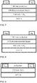
- Bottom gate, top contact FETs with structure of Si/SiO 2 /passivation layer/polymer (P1a, P2a or P3a )/Ag were fabricated by spin-coating from polymer solution on a highly n-doped silicon wafer with 200 nm of thermally-grown SiO 2 gate dielectrics passivated by PPCB or OTS-8. ( Figures 7 and 8 ). Distinct ambipolar characteristics were found at various thermal annealing temperatures.
- the hole and electron mobility passivated by PPCB amounts to 2.2 ⁇ 10 -2 and 1,2 ⁇ 10 -1 cm 2 V -1 s -1 , respectively, which is much higher than that from as-cast films (Table 6).
- the device also shows evident ambipolar behavior, exhibiting a hole and electron mobility of 9.4 ⁇ 10 -2 and 3.1 ⁇ 10 -3 cm 2 V -1 s -1 upon PPCB passivation, which is also much higher than that of the random P3a (Table 7).
- the distinct improvement of charge carrier mobility might be attributed to a more uniform orientation of the polymer chains in the solid-state.
- OTS-8 passivation hole mobility/electron mobility (cm 2 V -1 s -1 ) Polymer 25 °C 90 °C 110 °C 130 °C 150 °C P1a 4.8 ⁇ 10 -2 /2.4 ⁇ 10 -3 4.9 ⁇ 10 -2 /1.2 ⁇ 10 -3 4.5 ⁇ 10 -2 /2.0 ⁇ 10 -3 3.5 ⁇ 10 -2 /1.6 ⁇ 10 -3 4.5 ⁇ 10 -2 /1.6 ⁇ 10 -3 P2a 6.4 ⁇ 10 -2 /2.0 ⁇ 10 -2 6.3 ⁇ 10 -2 /5.3 ⁇ 10 -3 6.2 ⁇ 10 -2 /1.4 ⁇ 10 -3 9.4 ⁇ 10 -2 /3.1 ⁇ 10 -3 8.8 ⁇ 10 -2 /1.1 ⁇ 10 -3 P3a 6.3 ⁇ 10 -5 /2.1 ⁇ 10 -4 4.7 ⁇ 10 -5 /4.4 ⁇ 10 -5 3.2 ⁇ 10 -5 /3.7 ⁇ 10 -5 4.5 ⁇ 10 -5 /3.8 ⁇ 10 -6 7.1 ⁇ 10 -5 /3.3 ⁇ 10 -6
- the on/off ratio of the top contact device with silver electrode is approximately 500.
- gold with a deeper work function was selected as electrode and moreover, bottom gate, and bottom contact FETs were fabricated based on polymers with C16 side chain ( Figure 9 ). It was found that after thermal annealing at 110 °C for 10 min, the hole mobility reached 0.15 and 0.14 cm 2 V -1 s -1 for P1b and P2b, respectively, which are much higher than the 0.025 cm 2 V -1 s -1 obtained by random copolymer P3b. The current on/off ratios for all FETs are improved to ⁇ 10 4 for all devices (Table 8). Table 8.
- CDT and PT based narrow band-gap polymers with well-ordered main chain were prepared by precisely controlled regioselective chemistry.
- the resulted copolymers with regioregular structures show much longer conjugation length and better charge localization along the polymer backbone.
- the low-lying LUMO energy levels were realized for all polymers with the strong electron PT as acceptor, which resulted in the emergence of ambipolar properties for OFET devices. It was found that the regioregular polymers show much higher mobilities than the random copolymers under different OFET device configurations.
- Nuclear magnetic resonance (NMR) spectra were obtained on Bruker Avance DMX500 MHz spectrometer. Microwave assisted polymerizations were performed in a Biotage Initiator TM microwave reactor. Gel permeation chromatography (135 °C in 1,2,4-trichlorobenzene) was performed on a Polymer Laboratories PL220 Chromatograph. Differential scanning calorimetry (DSC) was determined by a TA Instruments DSC (Model Q-20) with about 5 mg polymers samples at a rate of 10 °C / min in the temperature range of -20 to 300 °C. UV-Vis absorption spectra were recorded on a Shimadzu UV-2401 PC dual beam spectrometer.
- Cyclic voltammetry (CVs) measurements were conducted using a standard three-electrode configuration under an argon atmosphere.
- a three-electrode cell equipped with a glassy carbon working electrode, a Ag wire reference electrode, and a Pt wire counterelectrode was employed.
- the measurements were performed in absolute acetonitrile with tetrabutylammonium hexafluorophosphate (0.1 M) as the supporting electrolyte at a scan rate of 50-100 mV/s.
- Polymer films were drop-cast onto the glassy carbon working electrode from a 2 mg/ml chloroform solution.
- CDT 4H -Cyclopenta[2,1- b :3,4- b ']dithiophene
- a dry three-neck round bottom flask was equipped with a Schlenk adapter, dropping funnel, and rubber septum. Under nitrogen, 4,4-didodecyl-4 H- cyclopenta[1,2- b :5,4- b ']dithiophene (0.51 g, 1 mmol) was dissolved in dry THF (12 ml) and cooled -78 °C using a dry ice/acetone cold bath. Under nitrogen, a solution of t -butyllithium (1.7 M in pentane, 1.25 ml, 2.1 mmol) was added dropwise over 15 minutes to the reaction vessel. The reaction was stirred at -78 °C under nitrogen for one hour and at 25 °C for 5 hours.
- tributyltin chloride (0.81 g, 2.5 mmol) was added dropwise over 5 minutes to the reaction vessel via syringe at -78 °C.
- the reaction was stirred at -78 °C under nitrogen for 1 hour and subsequently warmed to room temperature and stirred overnight.
- the mixture was then poured into deionized water (3 ⁇ 100 ml) and the organic phase was extracted with hexanes (3 ⁇ 100 ml).
- the organic phases were collected and washed with deionized water (5 ⁇ 100 ml), dried over sodium sulphate, filtered, and concentrated.
- a dry three-neck round bottom flask was equipped with a Schlenk adapter, dropping funnel, and rubber septum. Under nitrogen, 4,4-didodecyl-4 H -cyclopenta[1,2- b :5,4- b ']dithiophene (0.63 g, 1 mmol) was dissolved in dry THF (12 ml) and cooled -78 °C using a dry ice/acetone cold bath. Under nitrogen, a solution of t -butyllithium (1.7 M in pentane, 1.25 ml, 2.1 mmol) was added dropwise over 15 minutes to the reaction vessel. The reaction was stirred at -78 °C under nitrogen for one hour and at 25 °C for 5 hours.
- tributyltin chloride (0.81 g, 2.5 mmol) was added dropwise over 5 minutes to the reaction vessel via syringe at -78 °C.
- the reaction was stirred at -78 °C under nitrogen for 1 hour and subsequently warmed to room temperature and stirred overnight.
- the mixture was then poured into deionized water (3 ⁇ 100 ml) and the organic phase was extracted with hexanes (3 ⁇ 100 ml).
- the organic phases were collected and washed with deionized water (5 ⁇ 100 ml), dried over sodium sulphate, filtered, and concentrated.
- a dry three-neck round bottom flask was equipped with a Schlenk adapter, dropping funnel, and rubber septum. Under nitrogen, 4,4-didodecyl-4 H- cyclopenta[1,2- b :5,4- b ']dithiophene (0.51 g, 1 mmol) was dissolved in dry THF (12 ml) and cooled -78 °C using a dry ice/acetone cold bath. Under nitrogen, a solution of t -butyllithium (1.7 M in pentane, 2.35 ml, 4 mmol) was added dropwise over 15 minutes to the reaction vessel. The reaction was stirred at -78 °C under nitrogen for one hour and stirred at room temperature for 3 hours.
- a dry three-neck round bottom flask was equipped with a Schlenk adapter, dropping funnel, and rubber septum. Under nitrogen, 4,4-didodecyl-4 H- cyclopenta[1,2-b:5,4- b ']dithiophene (0.63 g, 1 mmol) was dissolved in dry THF (12 ml) and cooled -78 °C using a dry ice/acetone cold bath. Under nitrogen, a solution of t -butyllithium (1.7 M in pentane, 2.35 ml, 4 mmol) was added dropwise over 15 minutes to the reaction vessel. The reaction was stirred at -78 °C under nitrogen for one hour and stirred at room temperature for 3 hours.
- Monomer 2a (0.16 g, 0.16 mmol) was carefully weighed and added to a 2-5 mL microwave tube. The tube was transferred into a glovebox, and then Pd(PPh 3 ) 4 (4.4 mg, 0.005 mmol), and 3.2 mL of xylenes were added into the microwave tube. The tube was sealed, removed from the glovebox and subjected to the following reaction conditions in a microwave reactor: 80 °C for 2 min, 120 °C for 2 min, 160 °C for 2 min and 200 °C for 40 min. The reaction was allowed to cool leaving a viscous liquid containing some solid material.
- the mixture was precipitated in methanol, the resulted dark green fibers were collected and was re-dissolved in hot 1,2-dichlorobenzene. Then re-precipitated in methanol and collected via centrifugation.
- the collected solid fibers were loaded into a cellulose extraction thimble and washed successively with methanol (6 hours), acetone (6 hours), hexanes (12 hours) and chloroform (24 hours).
- the solid residue in the thimble was collected and dried followed by re-dissolved in hot 1,2-dichlorobenzene, filtrated and re-precipitated in methanol.
- the polymer was prepared following a previously reported microwave assisted polymerization technique. Two monomers 3a (0.18 g, 0.19 mmol) and 4a (0.17 g, 0.20 mmol) were carefully weighed and added to a 2-5 mL microwave tube. The tube was transferred into a glovebox, and then Pd(PPh 3 ) 4 (9 mg, 0.008 mmol) and 3 mL of Xylenes were added into the microwave tube. The tube was sealed, removed from the glovebox and subjected to the following reaction conditions in a microwave reactor: 80 °C for 2 min, 120 °C for 2 min, 160 °C for 2 min and 200 °C for 40 min. The reaction was allowed to cool leaving a viscous liquid containing some solid material.
- the reaction was allowed to cool to room temperature, then tributyl(thiophen-2-yl)stannane (20 ⁇ l) was added and the reaction was subjected to the following reaction conditions in a microwave reactor: 80 °C for 2 min, 130 °C for 2 min, 170 °C for 2 min and 200 °C for 20 min. After the reaction was cooled to room temperature, 2-bromothiophene (20 ⁇ l) was added and the end-capping procedure was repeated once again. The mixture was precipitated in methanol, collected via centrifugation.
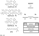
- indacene-PT based copolymers due to (1) the broad narrow-bandgap absorption, (2) the two thiophene rings rigidified together with a central phenyl ring, which can provide strong intermolecular interactions for ordered packing to improve the charge carrier mobility, and (3) the low-lying HOMO level of the copolymer will provide high open-circuit voltage (V oc ) (see Jen et al. [11])
- the reference polymer ( PIPT-RA ) was synthesized based on microwave assisted step-growth Stille copolymerization of M1 and 4,7-dibromo-pyridal[2,1,3]thiadiazole (PTBr 2 ), thus providing the polymer with the N-atom in the PT units randomly distributed along the polymer main chain. Both copolymers were purified by Soxhlet extraction using methanol, acetone, hexane and finally collected by chloroform. The polymer structures are shown in Scheme 5.
- GPC in 1,2,4-trichlorobenze (1,2,4-TCB) as eluent at 150 °C gave 46 kDa and 42 kDa for PIPT-RG and PIPT-RA, with a polydispersity of 2.3 and 2.8, respectively.
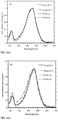
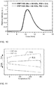
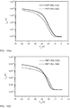
- UV-Vis absorption profiles of PIPT-RG and PIPT-RA in thin films are shown in Figure 12 .
- the absorption profile shapes are essentially the same for both copolymers.
- the short wavelength absorption bas ( ⁇ 417 nm) is assigned to a delocalized excitonic ⁇ - ⁇ * transition and the long wavelength absorption band (-715 nm) is ascribed to intramolecular charge transfer (ICT) interactions between the donor and acceptor moieties.
- ICT intramolecular charge transfer
- the absorption intensity of PIPT-RG is much stronger than that of PIPT-RA, indicating a much higher molar absorption coefficient of PIPT-RG.
- the optical band gaps (Eg) calculated from the absorption onset are determined to be 1.60 eV for PIPT-RG, which is slightly lower than that of 1.62 eV for PIPT-RA.
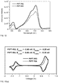
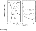
- E ox of PIPT-RA to that of PIPT-RG might be attributed to the more disordered vector of the PT unit along the polymer main chain, which would disturb the ⁇ -conjugated electron distribution along the polymer backbone leading to a slightly raised E ox .
- the highest occupied molecular orbital energy level (E HOMO ) and the lowest unoccupied molecular orbital energy level (E LUMO ) were calculated from the E ox and E red , on the basis of the assumption that E HOMO of ferrocene/ferrocenium (Fc/Fc + ) is at 4.8 eV relative to vacuum.
- the calculated E HOMO are -5.25 eV and -5.35 eV for PIPT-RG and PIPT-RA, respectively, and the E LUMO are both at -3.60 eV.
- the LUMO is mainly located in the acceptor and the HOMO is well-delocalized along the conjugated backbone, thus the two copolymers exhibited nearly identical E LUMO while slightly different E HOMO .
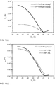
- the field-effect hole mobilities of PIPT-RG and PIPT-RA were extracted from the transfer characteristics ( Figure 14 ) of field-effect transistors (FETs) fabricated with bottom contact, bottom gate geometry using Au electrodes. It was noted that the calculated mobilities for PIPT-RG at room temperature of 0.13 cm 2 /Vs improved to 0.18 and 0.20 cm 2 /Vs after thermal annealing at 100 °C and 150 °C for 10 min, respectively. These are higher than for devices prepared under the same conditions with a PIPT-RA copolymer film of 0.04 cm 2 /Vs at room temperature, and 0.09 and 0.04 cm 2 /Vs attained after thermal annealing at 100 °C and 150 °C for 10 min, respectively.
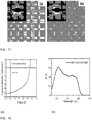
- the microstructures of two copolymer films were investigated by grazing incident X-ray diffraction (XRD).
- the samples were prepared on the top of (n-decyl)trichlorosilane (DTS) treated silicon substrate according to the same procedure of FET devices.
- the films were thermally annealed at 100 °C for 10 min.
- the scattering features with two distinct peaks centered at q values of 0.42 ⁇ -1 (spacing of 14.9 ⁇ ) and 1.42 ⁇ -1 (spacing of 4.4 ⁇ ) were realized for both copolymers.
- copolymers were used as donor materials for bulk heterojunction solar cells, the contact of active layer with following deposited metal is of particular importance.
- the surface morphologies of copolymer:PC 71 BM (1:4 in wt:wt) films were studies by tapping-mode atomic force microscopy (AFM), and the films were spin-casted from copolymer:PC 71 BM solution on the top of ITO/MoOx layer and followed the optimized conditions for solar cell devices.
- AFM tapping-mode atomic force microscopy
- NMR nuclear magnetic resonance
- spectra were obtained on Bruker Avance DMX500 MHz spectrometer.
- Gel permeation chromatography 150 °C in 1,2,4-trichlorobenzene was performed on a Polymer Laboratories PL220 Chromatograph.
- GPC with chloroform as eluent was performed in chloroform (with 0.25 v/v% triethylamine) on a Waters system, and the molecular weight of polymers were estimated relative to linear PS standards.
- Differential scanning calorimetry (DSC) was determined by a TA Instruments DSC (Model Q-20) with about 5 mg polymers samples at a rate of 10 °C / min in the temperature range of -20 to 300 °C.
- UV-Vis absorption spectra were recorded on a Shimadzu UV-2401 PC dual beam spectrometer.
- Cyclic voltammetry (CV) measurements were conducted using a standard three-electrode configuration under an argon atmosphere. A three-electrode cell equipped with a glassy carbon working electrode, a Ag wire reference electrode, and a Pt wire counterelectrode was employed. The measurements were performed in absolute acetonitrile with tetrabutylammonium hexafluorophosphate (0.1 M) as the supporting electrolyte at a scan rate of 50-100 mV/s. Polymer films for CV test were drop-casted onto the glassy carbon working electrode from a 2 mg/mL chloroform solution.
- Grazing incident X-ray diffraction was performed on Rigaku Smart instrument.
- Atomic force microscopy (AFM) was recorded on Asylum MFP3D instrument. All the samples were prepared identical to optimized device structure and conditions prior to electrode deposition.
- Transmission Electron Microscope (TEM) was performed on FEI Tecnai G2 Sphera Microscope instrument. The samples were prepared by spin-casting on the top of glass substrate and floated in water, following by put on the top of copper grid.
- the reaction was stirred at -78 °C under nitrogen for one hour. Then trimethyltin chloride (0.60 g, 3.0 mmol) was added dropwise over 5 minutes to the reaction vessel via syringe at -78 °C. The reaction was stirred at -78 °C under nitrogen for 1 hour and subsequently warmed to room temperature and stirred overnight. The mixture was then poured into deionized water (3 ⁇ 100 mL) and the organic phase was extracted with hexanes (3 ⁇ 100 mL). The organic phases were collected and washed with deionized water (5 ⁇ 100 mL), dried over sodium sulphate, filtered, and concentrated.
- the reaction was allowed to cool to room temperature, then freshly distilled xylenes (2 mL) and tributyl(thiophen-2-yl)stannane (20 ⁇ l) was added and the reaction was subjected to the following reaction conditions in a microwave reactor: 80 °C for 2 min, 130 °C for 2 min, 170 °C for 2 min and 200 °C for 20 min.
- 2-bromothiophene (20 ⁇ l) was added and the reaction was subjected to the following reaction conditions in a microwave reactor: 80 °C for 2 min, 130 °C for 2 min, 170 °C for 2 min and 200 °C for 20 min.
- the mixture was precipitated in methanol, collected via centrifugation, then re-dissolved in hot 1,2-dichlorobenzene and re-precipitated in methanol and collected via centrifugation.
- the collected solid fibers were loaded into a cellulose extraction thimble and washed successively with methanol (12 hours), acetone (12 hours) and hexanes (12 hours), and then chloroform (2 hours) to collected the copolymer.
- the solid residue in the thimble was collected and dried followed by re-dissolved in hot 1,2-dichlorobenzene, filtrated and re-precipitated in methanol.
- the polymerization was performed following the procedure for PIPT-RG in microwave reactor.
- the monomer M1 246.6 mg, 0.2 mmol
- monomer M2 4,7-dibromo-pyridal[2,1,3]thiadiazole (59.0 mg, 0.2 mmol)
- Pd(PPh 3 ) 4 (11.5 mg, 0.01mmol
- xylenes 3 mL
- the resulted dark-green solid was dried over high vacuum line to give 168.5 mg of polymer, yield 81 %.
- the UPS analysis chamber was equipped with a hemispherical electron-energy analyzer (Kratos Ultra spectrometer), and was maintained at 1.33 ⁇ 10 -7 Pa.
- PSCs Polymer solar cells with conventional device architecture of ITO/MoO X / polymer:PCBM/Al were fabricated according to the following procedure.
- the ITO-coated glass substrates were firstly cleaned by ultrasonic treatment in detergent, deionized water, acetone and isopropyl alcohol for 30 minutes each, and subsequently dried in an oven overnight.
- MoO X film was deposited onto ITO substrates by thermal evaporation in a vacuum of about 1 ⁇ 10 -6 Torr. The evaporation rate was 0.1 ⁇ /s.
- PSCs Characterization The thickness of the multilayer was measured with a profilometer and Atomic Force Microscope (AFM), respectively. Current density-voltage ( J-V ) characteristics were measured using a Keithley 2602 Source measure Unit, under solar simulation conditions of 100 mW/cm 2 AM 1.5 G using a 300 W Xe arc lamp with an AM 1.5 global filter. The illumination intensity of the solar simulator was measured using a standard silicon photovoltaic with a protective KG1 filter calibrated by the National renewable Energy Laboratory.
- AFM Atomic Force Microscope
- Figure 18 (a) illustrates the J - V characteristics of the optimized BHJ solar cell using PIPT-RG as donor materials.
- the optimized blend ratio of PIPT and fullerene is 1:4. Detailed comparisons of different blend ratio are not shown here.
- PIPT-RG as donor materials shows a PCE of 5.5%.
- the IPCE spectrum shown in Figure 12 18 (b) is in good agreement with the J-V values.
- the aqueous MoO x solution was prepared by hydration method according to the procedure reported by Liu et al ( Fengmin Liu, Zhiyuan Xie, et al. Solar Energy Materials & Solar Cells. 2010, 94, 94842-845 ).
- Ammonium molybdate ((NH 4 ) 6 Mo 7 O 24 ) was dissolved in water to form 0.01 mol/L solution, marked as solution A.
- 2 mol/L hydrochloric acid (HCl) water solution was marked as solution B.
- Solution B was dropped into solution A until the pH value of the mixed solution was adjusted between 1.5 and 2.0. This mixed solution was marked as solution C, which is the aqueous MoO x solution.
- PSCs Pre-thermal annealing
- Polymer solar cells with conventional device architecture of ITO/MoO 3 / polymer: PCBM//A1 were fabricated according to the following procedure.
- the ITO-coated glass substrates were firstly cleaned by ultrasonic treatment in detergent, deionized water, acetone and isopropyl alcohol for 30 minutes each, and subsequently dried in an oven overnight.
- MoO x (filtered at 0.45 ⁇ m) was spin-coated from aqueous solution at 5000 rpm for 40 s to form a film of ⁇ 8 nm thickness.
- the substrates were then baked at 160°C for 25 min in air, and moved into a glovebox for spin-casting the active layer.
- Two solutions containing a mixture of PIPT-RA:PC 71 BM and PIPT-RG:PC 71 BM with different blend ratios in o-DCB with a concentration of 10 mg/ml were spin-casted on top of MoO x layer, respectively.
- the film thickness of ⁇ 90 nm was optimized by controlling the spin-casting speed.
- the BHJ films were annealed at 100°C for 10 min.
- the cathode (Al, ⁇ 100 nm) was deposited through a shadow mask by thermal evaporation in a vacuum of about 3 x 10 -6 Torr.
- the active area of the devices was 0.106 cm 2 .
- PSCs Post-thermal annealing: Polymer solar cells with conventional device architecture of ITO/MoO 3 / polymer:PCBM//A1 were fabricated according to the following procedure. The ITO-coated glass substrates were firstly cleaned by ultrasonic treatment in detergent, deionized water, acetone and isopropyl alcohol for 30 minutes each, and subsequently dried in an oven overnight. After treated with UV/ozone for 20 min, MoO x (filtered at 0.45 ⁇ m) was spin-coated from aqueous solution at 5000 rpm for 40 s to form a film of ⁇ 8 nm thickness.
- the substrates were then barked at 160°C for 25 min in air, and moved into a glovebox for spin-casting the active layer.
- Two solutions containing a mixture of PIPT-RA:PC 71 BM and PIPT-RG:PC 71 BM with different blend ratio in o-DCB with a concentration of 10 mg/ml were spin-casted on top of MoO x layer, respectively.
- the film thickness of ⁇ 90 nm was optimized by controlling the spin-casting speed.
- the cathode Al, ⁇ 100 nm
- the devices were annealing at 100°C for 10 min.
- the active area of device was 0.106 cm 2 .
- PSCs Polymer solar cells with conventional device architecture of ITO/MoO 3 / polymer:PCBM/A1 were fabricated according to the following procedure.
- the ITO-coated glass substrates were firstly cleaned by ultrasonic treatment in detergent, deionized water, acetone and isopropyl alcohol for 30 minutes each, and subsequently dried in an oven overnight. After treated with UV/ozone for 20 min, MoO x (filtered at 0.45 ⁇ m) was spin-coated from aqueous solution at 5000 rpm for 40 s to form a film of ⁇ 8 nm thickness.
- the substrates were then barked at 160°C for 25 min in air, and moved into a glovebox for spin-casting the active layer.
- CPE Polymer solar cells with conventional device architecture of ITO/MoO 3 / polymer:PCBM/Al were fabricated according to the following procedure.
- the ITO-coated glass substrates were firstly cleaned by ultrasonic treatment in detergent, deionized water, acetone and isopropyl alcohol for 30 minutes each, and subsequently dried in an oven overnight. After treated with UV/ozone for 20 min, MoO x (filtered at 0.45 ⁇ m) was spin-coated from aqueous solution at 5000 rpm for 40 s to form a film of ⁇ 8 nm thickness.
- the substrates were then barked at 160°C for 25 min in air, and moved into a glovebox for spin-casting the active layer.
- PSCs Characterization The thickness of the multilayer was measured with a profilometer and Atomic Force Microscope (AFM), respectively. Current density-voltage ( J-V ) characteristics were measured using a Keithley 2602 Source measure Unit, under solar simulation conditions of 100 mW/cm 2 AM 1.5 G using a 300 W Xe arc lamp with an AM 1.5 global filter. The illumination intensity of the solar simulator was measured using a standard silicon photovoltaic with a protective KG1 filter calibrated by the National renewable Energy Laboratory.
- AFM Atomic Force Microscope
- Figure 19(a) illustrates the J - V characteristics of the optimized BHJ solar cell based on PIPT-RA and PIPT-RG as donor materials, respectively. Detailed comparisons of different blend ratio are summarized in Table 11. It could be seen that the performance of PIPT-RG devices is much better than that of PIPT-RA devices, corresponding to PCE increases of from 3.4% to 5.1%. From Figure 19(b) we could see that the IPCE spectrum of PIPT -RG based devices is more broadened than that of PIPT -RA based devices, which is in good agreement with the increased J SC . Table 11.
- post-thermal annealing annealing devices after evaporation cathode
- DIO additive
- spin-casting CPE as interfacial layer between the active layer and cathode
- ZnO precursor Preparation of the ZnO Precursor : The ZnO precursor was prepared by dissolving zinc acetate dihydrate (Zn(CH 3 COO) 2 ⁇ 2H 2 O, Aldrich, 99.9%, 1 g) and ethanolamine (NH 2 CH 2 CH 2 OH, Aldrich, 99.5%, 0.28 g in 2-methoxyethanol (CH 3 OCH 2 CH 2 OH, Aldrich, 99.8%, 10 mL) under vigorous stirring for 12 h for the hydrolysis reaction in air.
- ZnO precursor was prepared by dissolving zinc acetate dihydrate (Zn(CH 3 COO) 2 ⁇ 2H 2 O, Aldrich, 99.9%, 1 g) and ethanolamine (NH 2 CH 2 CH 2 OH, Aldrich, 99.5%, 0.28 g in 2-methoxyethanol (CH 3 OCH 2 CH 2 OH, Aldrich, 99.8%, 10 mL) under vigorous stirring for 12 h for the hydrolysis reaction in air.
- Inverted solar cells were fabricated on ITO-coated glass substrates.
- the ITO-coated glass substrates were first cleaned with detergent, ultrasonicated in water, actone and isopropyl alcohol, and subsequently dried overnight in an oven.
- the ZnO precursor solution was spin-cast on top of the ITO-glass substrate.
- the films were annealed at 150 °C for 1 h in air.
- the ZnO film thickness was approximately 30 nm, as determined by a profilometer.
- the ZnO-coated substrates were transferred into a glove box.
- a solution containing a mixture of PIPT -RG:PC 7 ,BM (1:4) in o-DCB with a concentration of 10 mg/ml was spin-casted on top of a ZnO film with thickness of approximately 80 nm, respectively.
- the BHJ film was heated at 100 °C for 10 min.
- a thin layer of MoO x film ( ⁇ 6 nm) was evaporated on top of the BHJ layer.
- the anode (Ag, ⁇ 60 nm) was deposited through a shadow mask by thermal evaporation in a vacuum of about 3 ⁇ 10 -6 Torr.
- the active area of device was 0.05 cm 2 .
- PSCs Characterization The thickness of multilayers was measured with a profilometer and Atomic Force Microscope (AFM), respectively. Current density-voltage ( J-V ) characteristics were measured using a Keithley 2602 Source measure Unit, under solar simulation conditions of 100 mW/cm 2 AM 1.5 G using a 300 W Xe arc lamp with an AM 1.5 global filter. The illumination intensity of the solar simulator was measured using a standard silicon photovoltaic with a protective KG1 filter calibrated by the National renewable Energy Laboratory.
- AFM Atomic Force Microscope
- Figure 21 (a) illustrates the J - V characteristics of the optimized BHJ solar cell based on PIPT-RG as donor material.
- the device shows a nice open circle voltage of 0.88 V and short circle current of 14.1 mA/cm 2 .
- the FF is relatively low
- the PCE is up to 6.2 %, which is very comparable to our conventional devices. This consistent value indicated that even when using different device structures, region-regular PIDTPT polymer can distinctly improved OPV devices.
- the inventors realize that replacement of the carbon bridge in CDT unit by a silicon bridge, with the new donor of silolo[3,2- b :4,5- b' ]dithiophene (SDT), might decrease the highest occupied molecular orbital (HOMO) energy level, and that OPVs incorporating SDT-PT-based conjugated copolymers might show higher Voc values than that of CDT-PT copolymers.
- SDT-PT-based regioregular copolymers as the active layer can achieve improved J SC and PCE in OPVs.
- the tube was sealed and subjected to the following reaction conditions in a microwave reactor: 80 °C for 2 min, 130 °C for 2 min, 170 °C for 2 min and 200 °C for 40 min.
- the reaction was allowed to cool to room temperature, then tributyl(thiophen-2-yl)stannane (20 ⁇ l) was added and the reaction was subjected to the following reaction conditions in a microwave reactor: 80 °C for 2 min, 130 °C for 2 min, 170 °C for 2 min and 200 °C for 20 min.
- 2-bromothiophene (20 ⁇ l) was added and the end-capping procedure was repeated once again.
- the mixture was precipitated in methanol, collected via centrifugation.
- PC 71 BM (99.5%) was purchased from Nano-C. Chlorobenzene (CB, anhydrous, 99%) was supplied by Sigma-Aldrich Company. All materials were used as received.
- PSCs Polymer solar cells with conventional device architecture of ITO/PEDOT:PSS/PSDTPT:PCBM/Al were fabricated according to the following procedure.
- the ITO-coated glass substrates were firstly cleaned by ultrasonic treatment in detergent, deionized water, acetone and isopropyl alcohol for 30 minutes each, and subsequently dried in an oven overnight. After treated with UV/ozone for 20 min, PEDOT:PSS (Baytron P VP AI 4083, filtered at 0.45 ⁇ m) was spin-coated from aqueous solution at 4000 rpm for 40 s to form a film of ⁇ 40 nm thickness.
- the substrates were barked at 140°C for 10 min in air, and then moved into a glovebox for spin-casting the active layer.
- Two solution containing with PSDTPT2-EH:PC 71 BM (1:1, w/w) and PSDTPTR-EH:PC 71 BM (1:1, w/w) in CB with a concentration of 10 mg/ml were then spin-casted on top of PEDOT:PSS layer, which were marked as device I and device II, respectively.
- the film thickness of ⁇ 80 nm was controlled by adjusting the spin-casting speed.
- the BHJ films were dried at 70°C for 10 min. After that, the cathode (Al, ⁇ 100 nm) was deposited through a shadow mask by thermal evaporation in a vacuum of about 3 ⁇ 10 -6 Torr.
- the active area of device was 0.106 cm 2 .
- PSCs Characterization The thickness of the active layer and PEDOT:PSS was measured with a profilometer. Current density-voltage ( J-V ) characteristics were measured using a Keithley 2602 Source measure Unit, under solar simulation conditions of 100 mW/cm 2 AM 1.5 G using a 300 W Xe arc lamp with an AM 1.5 global filter. The illumination intensity of the solar simulator was measured using a standard silicon photovoltaic with a protective KG1 filter calibrated by the National renewable Energy Laboratory.
- Figure 22 illustrates the J - V characteristics of the two devices, and the detailed comparisons are summarized in Table 12.
- the short circuit current density ( J SC ) of device II increases as much as four times (from 2.41 to 9.03 mA/cm 2 ) compared with that of device I using the regionrandom copolymers.
- the J SC is not only determined by the number of absorbed photons, but also heavily influenced by the component morphology in the active layer. Therefore, a remarkable increase in J SC for the device II implies that the morphology of the active layer has been substantially improved.
- High mobility lies in the heart of practical applications for organic electronics. High mobility enables low operating voltage and less energy consumption in organic thin film transistors (OTFTs). Recently, narrow bandgap donor-acceptor (DA) copolymers are attracting researchers' attention. The combination of DA moieties on polymer chain can induce preferred charge transfer between DA units with different electron affinities. Therefore, delocalization, improved transport and higher mobility are expected.
- DA narrow bandgap donor-acceptor
- Molecular structures of the three polymers, device architecture, and work functions are shown in Figure 23 .
- larger molecular weight and films with improved structural order are required.
- low polydispersity index (PDI) is important as well as molecular weight.
- the high mobility, over 2 cm 2 /Vs, after annealing could be correlated to the higher degree of structural order in films of high molecular weight rr-P2.
- To push mobility even higher than 2.5 cm 2 /Vs inducing higher molecular weight and more ordering in polymer film are promising.
- To further increase the molecular weight by GPC is impractical because of the required collecting time and the quantity of the fractionated solution.
- FIG. 24(a) and 24(b) The transfer and output characteristics of the OTFTs made of rr-P2 are shown in Figure 24(a) and 24(b) .
- the polymer film was drop cast on a prepatterned substrate with bottom contact (BC) architecture made of gold.
- the SiO 2 gate dielectric was passivated by decyl(trichloro)silane (DTS).
- DTS decyl(trichloro)silane
- Figure 24(a) shows clear transistor behavior with linear and saturation regimes and on-off ration 6 ⁇ 10 6 .
- the positive shift of threshold voltage from negative V G to V G 20 V elucidates the existence of hole traps on the interface of gold and polymer.
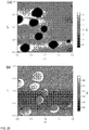
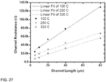
- Table 13 is a mobility table showing drop casted films prepared from different concentration solutions after different annealing temperatures. The highest mobility value 2.5 cm 2 /Vs, was achieved from the film prepared by 0.025 wt% solution and annealed at 350 °C. Even though the mobility values continuously increase with annealing temperature, the numbers saturate after 200 °C, mainly varying from 1.8 to 2.3 cm 2 /Vs.
- the dark spots in the image are actually holes in the film.
- R c contact resistance
- PCDTPT2 (P2) was originally synthesized with 55 kDa and PDI> 4.
- GPC gel permeated chromatography
- the high molecular weight P2 was dissolved in chlorobenzene with 0.1, 0.075, 0.05, and 0.025 wt% for drop casting on bottom contact substrates passivated by decyl(trichloro)silane.
- the casted substrates were kept in a glovebox with oxygen level less than 2 ppm, drying for 6 hours. All devices were tested in a nitrogen environment and data were collected by Keithley 4200.
Description
- The invention relates to conjugated polymers and methods of making the same.
- Organic π-conjugated polymers are attractive materials for use in the active layer, as they combine good absorption and emission characteristics with efficient charge carrier mobility and have the ability to be solution processed onto flexible substrates. Recent advances in the field have seen organic field effect transistors (OFET) achieve charge carrier mobility on the order of 1.0 cm2 V-1 s-1 [1] and organic photovoltaic (OPV) devices reach power conversion efficiencies over 7% [2], While these results are promising for the field, there still exits a complexity of correlating molecular structure to optical and electronic properties. Among the available narrow band-gap materials, donor-acceptor copolymers based on cyclopenta[2,1-b:3,4-b']dithiophene (CDT) and benzothiadiazole (BT) have attracted considerable attention due to the high charge carrier mobility and excellent photovoltaic performance [20].. Mullen and co-workers have eloquently demonstrated that CDT-BT copolymers with linear side chains and high molecular weights, p-type FETs with mobilities on the order of 1.4-3.3 cm2 V-1 s-1 [3].
- The incorporation of a nitrogen atom into the acceptor unit of CDT-BT copolymers results in the narrowing of the optical bandgap and the emergence of these materials to selectively bind Lewis acids [4]. The replacement of the BT unit with the pyridal[2,1,3]thiadiazole (PT) acceptor unit results in a higher electron affinity across the polymeric backbone leading to a decreased LUMO level of polymer. Copolymers based on PT and carbazole reported by Lerclerc et al. [5] have fairly low molecular weights (ca. 4-5 kDa), and the efficiencies of the fabricated solar cells (under 1%) are much lower than predicated. You and co-workers have demonstrated that by introducing two alkyl chains to the 4-position of the thienyl unit could lead to a more soluble PT based acceptor (DTPyT), and allows access to polymers with high molecular weights and excellent photovoltaic efficiency up to 6.32% [6]. In each case, however, the nature of the step-growth polymerization strategy leads to these polymer systems having a regiorandom origination of the pyridal-N atom along the polymeric backbone.
- The inventors understand that regioregularity can have a great impact on the properties of polymers [7]. For instance, enhanced regioregularity of poly(3-alkylthiophene) can impart to polymers a higher crystallinity, red-shifted optical absorption, higher conductivity, and smaller band-gap [8]. The inventors have surmised that for a polymer based on an asymmetric PT unit, a regioregular backbone structure with more effective electron localization can result in a higher charge carrier mobility and enhanced photovoltaic performance. Recognizing that for the copolymerization of distannyl CDT monomers and 4,7-dibromo-pyridal[2,1,3]thiadiazole (PTBr2) as starting material, the resulted polymer would not be truly random because the bromine at the electron-deficient C4-position of PTBr2 is more favorable for coupling than the C7-position [9], the inventors take advantage of this difference by preparing regiochemically precise backbones of PT-based polymers using specific synthetic procedures.
- In one aspect, there is provided a regioregular donor-acceptor copolymer comprising a regioregular conjugated main chain section, said regioregular conjugated main chain section having a repeat unit that comprises a pyridine of the structure


- In a further aspect, there is provided a method of preparing the regioregular donor-acceptor copolymer of the invention, the method comprising: regioselectively preparing a monomer; and reacting the monomer to produce said donor-acceptor copolymer, wherein the regioselectivity of preparing the monomer is 95% or greater. Also provided is an electronic device that includes the regioregular polymer.
- The regioregular polymer includes a regioregular conjugated main chain section having a repeat unit that includes a pyridine of the structure


- In some embodiments, each substituted or non-substituted aromatic functional group of the pyridine and the dithiophene independently includes one or more alkyl or aryl chains. In particular embodiments, the one or more alkyl or aryl chains are each independently a C6-C30 substituted or non-substituted alkyl chain, -(CH2CH2O)n (n = 2 ∼ 20), C6H5, -CnF(2n+1) (n = 2 ∼ 20), -(CH2)nN(CH3)3Br (n = 2 ∼ 20), -(CH2)nN(C2H5)2 (n = 2 ∼ 20), 2-ethylhexyl, PhCmH2m+1 (m=1-20), -(CH2)nSi(CmH2m+1)3 (m, n = 1 to 20), or -(CH2)nSi(OSi(CmH2m+1)3)x(CpH2p+1)y (m, n, p = 1 to 20, x+y=3).
- In some embodiments, the substituted or non-substituted alkyl, aryl or alkoxy chain of the dithiophene can be a C6-C30 substituted or non-substituted alkyl, aryl or alkoxy chain, -(CH2CH2O)n (n = 2 ∼ 20), C6H5, -CnF(2n+1) (n = 2 ∼ 20), -(CH2)nN(CH3)3Br (n = 2 ∼ 20), -(CH2)nN(C2H5)2 (n = 2 ∼ 20), 2-ethylhexyl, PhCmH2m+1 (m=1-20), -(CH2)nSi(CmH2m+1)3 (m, n = 1 to 20), or -(CH2)nSi(OSi(CmH2m+1)3)x(CpH2p+1)y (m, n, p = 1 to 20, x+y=3).
- In some embodiments X of the dithiophene can be C or Si.
- In some embodiments of the regioregular polymer, the pyridine is a pyridine unit of Table 1 (which is described below). In some embodiments, the repeat unit further includes a dithiophene unit of Table 2 (which is described below). In certain embodiments, the pyridine unit is


- In some embodiments of the regioregular polymer, the repeat unit includes


- A device including any regioregular polymer described herein is provided. The device can be, but is not limited to, a field effect transistor, organic photovoltaic device, polymer light emitting diode, organic light emitting diode, organic photodetector, or biosensor. In the device, the regioregular polymer can form an active semiconducting layer.
- The term "regioregular," "regioregularly" or "regioregularity" in relation to a polymer or a section of a polymer means the non-random orientation or arrangement of the pyridal-N along the polymer backbone. In some regioregular embodiments, the nitrogen atom of the pyridine faces in the same direction in all or a majority of the repeat units of the polymer or polymer section. For example, in the repeat unit of
Scheme 1 below, the pyridal nitrogen atom of the PT unit faces the CDT unit. If we define the end of PT next to the pyridal nitrogen atom as the head, and the other end as the tail, then all or a majority of the PT units in the copolymers ofScheme 1 adopted a head-to-tail arrangement next to each other. In other regioregular embodiments, all or a majority of the repeat units of the polymer or polymer section have two pyridine units, with the nitrogen atoms of the pyridine units oriented toward each other. For example, in the repeat unit ofScheme 2 below, the pyridal nitrogen atom of one PT unit is oriented towards the pyridal nitrogen atom of the other PT unit, which is a head-to-head connection through the CDT unit. - For a more complete understanding of the present invention, reference is now made to the following descriptions taken in conjunction with the accompanying drawings, in which:
-
Figure 1 is a panel of 1H NMR spectra of P1b, P2b and P3b in d-TCE at 110 °C; -
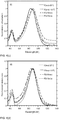
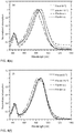
Figure 2 is a panel of UV-Vis spectra of P1a, P2a and P3a (a) in o-DCB solutions at 25 °C and (b) as casting films; -
Figure 3 is a panel showing output (a) and transfer (b) characteristics of FET devices based on P1a with PPCB as passivation layer; -
Figure 4 is a panel of UV-vis spectra of polymers (a) P1a, (b) P1b, (c) P2a, (d) P2b, (e) P3a and (f) P3b in o-DCB solutions at 25 or 110 °C, and in films as casting (a.c.) or after thermal annealing (t.a.) at 110 °C for 15 min; -
Figure 5 is a panel of DSC curves of polymers with C12 side chain (a) and C16 side chain (b); -
Figure 6 is a panel of CV curves of polymers with C12 side chain (a) and C16 side chain (b); -
Figure 7 is a schematic drawing of a device structure with PPCB passivation; -
Figure 8 is a schematic drawing of a device structure with OTS-8 passivation; and -
Figure 9 is a schematic drawing of a bottom-gate, bottom contact device structure. -
Figure 10 is a composite drawing of GPC profiles of copolymers with chloroform as eluent. -
Figure 11 is a composite drawing of DSC characteristics of copolymers. -
Figure 12 is a composite drawing of UV-Vis spectra of PIPT-RG and PIPT-RA films (thickness ∼ 30 nm). -
Figure 13 is a panel of (a) CV curves and (b) UPS measurements of polymer films. -
Figure 14 is a panel of output and transfer characteristics (VD = -60 V) for FETs based on PIPT-RG (black dot) and PIPT-RA (red dot) at room temperature (a) and (d), thermal annealed at 100 °C for 10 min (b) and (e), and thermal annealed at 150 °C for 10 min (c) and (f). FET with channel L = 20 µm, W = 1 mm. -
Figure 15 is a composite drawing of grazing incident XRD of PIPT-RG and PIPT-RA polymer films. -
Figure 16 is a panel of topographic AFM images (2 µm × 2 µm) of (a) PIPT-RG:PC71BM (1:4) and (b) PIPT-RA:PC71BM (1:4) (b) blend films. -
Figure 17 is a panel of TEM images of (a) PIPT-RG:PCBM (1:4) and (b) PIPT-RA:PCBM (1:4) (b) films. -
Figure 18 is a panel showing J-V characteristics (a) and IPCE (b) of thermal evaporated MoOX PSC devices based on regioregular and regiorandom PIPT polymers. -
Figure 19 is a panel showing J-V characteristics (a) and IPCE (b) of solution-processed MoOX PSC devices based on regioregular and regiorandom PIPT polymers. -
Figure 20 is a panel showing J-V characteristics of devices (a) post-thermal annealing, and (b) with additive. -
Figure 21 is a panel showing J-V characteristics (a) and IPCE (b) of inverted structure devices based on PIPT-RG polymer -
Figure 22 is a composite drawing of density-voltage (J-V) characteristics of PSC devices based on PSDTPTR-EH (A) and PSDTPT2-EH (B) copolymers. -
Figure 23 is a panel showing molecular structures of polymers and decyl(trichloro)silane, and device architecture. -
Figure 24 is a panel showing (a) the transfer characteristic of an organic TFT after annealing at 350 °C, and b) the output characteristic of the same OTFT. -
Figure 25 are atomic force microscopy images of (a) the height image of a polymer film after 350 °C annealing obtained by the tapping mode of AFM, and (b) the phase image correlated to 24(a). -
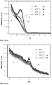
Figure 26 is a panel of (a) out-of-plane XRD spectra after annealing at various temperatures, and (b) correlated in-plane XRD. -
Figure 27 is a composite drawing of contact resistances at different annealing temperatures obtained by transfer line measurement. - In the method of preparing a regioregular polymer, a monomer is regioselectively prepared. In some embodiments, the monomer is prepared by reacting halogen-functionalized PT with organotin-functionalized cyclopenta[2,1-b:3,4-b']dithiophene. The reaction can be carried out at a temperature in the range of about 50 °C to about 150 °C. In other embodiments the monomer is prepared by reacting halogen-functionalized PT with organotin-functionalized indaceno[1,2-b:5,6-b']dithiophene (IDT), where the reaction can be carried out at a temperature in the range of about 50 °C to about 150 °C. In other embodiments the monomer is prepared by reacting halogen-functionalized PT with organoboron-functionalized cyclopenta[2,1-b:3,4-b']dithiophene or organboron-functionalized indaceno[1,2-b:5,6-b']dithiophene (IDT), where the reaction can be carried out at a temperature in the range of about 50 °C to about 150 °C. In some embodiments the monomer is prepared by reacting halogen-functionalized PT with cyclopenta[2,1-b:3,4-b']dithiophene or indaceno[1,2-b:5,6-b']dithiophene (IDT) by direct arylation polyerization, in which direct arylation allows the formation of carbon-carbon bonds between aromatic units having activated hydrogen atoms without the use of organometallic intermediates, where the reaction can be carried out at a temperature in the range of about 50 °C to about 150 °C.
- The halogen-functionalized PT can have the following structure:

- The organotin-functionalized cyclopenta[2,1-b:3,4-b']dithiophene can have the following structure:


- The term "alkyl" refers to a branched or unbranched saturated hydrocarbyl group such as methyl, ethyl, n-propyl, isopropyl, n-butyl, isobutyl, t-butyl, octyl, decyl and the like. The term "aryl" refers to an aromatic hydrocarbyl group containing a single aromatic ring or multiple aromatic rings that are fused together, linked covalently, or linked to a common group such as a methylene or ethylene moiety. The term "alkoxy" refers to an alkyl group bound through a single, terminal ether linkage. The term "substituted" refers to a hydrocarbyl group in which one or more bonds to a hydrogen atom contained within the group is replaced by a bond to a non-hydrogen atom of a substituent group. Examples of non-hydrogen atoms include, but are not limited to, carbon, oxygen, nitrogen, phosphorus, and sulfur. Examples of substituent groups include, but are not limited to, halo, hydroxy, amino, alkoxy, aryloxy, nitro, ester, amide, silane, siloxy, and hydrocarbyl groups. The substituent can be a functional group such as hydroxyl, alkoxy, thio, phosphino, amino, or halo.
- In particular embodiments of the cyclopenta[2,1-b:3,4-b']dithiophene or indaceno[1,2-b:5,6-b']dithiophene: the substituted or non-substituted alkyl, aryl or alkoxy chain can be a C6-C30 substituted or non-substituted alkyl or alkoxy chain, -(CH2CH2O)n (n = 2 ∼ 20), C6H5, -CnF(2n+1) (n = 2 ∼ 20), -(CH2)nN(CH3)3Br (n = 2 ∼ 20), -(CH2)nN(C2H5)2 (n = 2 ∼ 20), 2-ethylhexyl, PhCmH2m+1(m=1-20), -(CH2)nSi(CmH2m+1)3 (m, n = 1 to 20), or -(CH2)nSi(OSi(CmH2m+1)3)x(CpH2p+1)y (m, n, p = 1 to 20, x+y=3); and/or X can be Si.
- In some embodiments, the halogen-functionalized PT and/or the organotin-functionalized cyclopenta[2,1-b:3,4-b']dithiophene are compounds of
Scheme Scheme 4. - The regioselectively prepared monomer can have the following structure:


- In the method, the monomer is regioselectively prepared, then the monomer is reacted or polymerized to form a regioregular polymer having a regioregular conjugated main chain section. To form the regioregular polymer when the monomer is a CDT-PT monomer , the monomer can be reacted to itself, or reacted to another monomer containing a cyclopenta[2,1-b:3,4-b']dithiophene unit. When the monomer is a PT-IDT-PT monomer, the monomer can be reacted to another monomer containing an IDT-PT unit. The polymerization reaction can take place at a temperature in the range of about 80 °C to about 200 °C when the monomer is a CDT-PT monomer, and can take place at a temperature in the range of about 80 °C to about 200 °C when the monomer is a PT-IDT-PT monomer. The regioregular conjugated main chain section can comprise 5-100, or more, contiguous repeat units. In some embodiments, the number of repeat units is in the range of 10-40 repeats. The regioregularity of the conjugated main chain section can be 95% or greater.
- The regioregular polymer has a main chain section that includes a repeat unit containing a pyridine of the structure


- In embodiments of the regioregular polymer, the repeat unit of the regioregular conjugated main chain section can contain a pyridine unit of Table 1, where each R is independently a substituted or non-substituted alkyl chain, which can be a C6-C30 substituted or non-substituted alkyl chain, -(CH2CH2O)n (n = 2 ∼ 20), C6H5, -CnF(2n+1) (n = 2 ∼ 20), -(CH2)nN(CH3)3Br (n = 2 ∼ 20), -(CH2)nN(C2H5)2 (n = 2 ∼ 20), 2-ethylhexyl, PhCmH2m+1(m=1-20), -(CH2)nSi(CmH2m+1)3 (m, n = 1 to 20), or -(CH2)nSi(OSi(CmH2m+1)3)x(CpH2p+1)y (m, n, p = 1 to 20, x+y=3); in some embodiments, the R groups can be the same.

- In embodiments of the regioregular polymer, the repeat unit of the regioregular conjugated main chain section can contain a dithiophene unit of Table 2, where each R is independently a substituted or non-substituted alkyl, aryl or alkoxy chain, which can be a C6-C30 substituted or non-substituted alkyl or alkoxy chain, -(CH2CH2O)n (n = 2 ∼ 20), C6H5, -CnF(2n+1) (n = 2 ∼ 20), -(CH2)nN(CH3)3Br (n = 2 ∼ 20), -(CH2)nN(C2H5)2 (n = 2 ∼ 20), 2-ethylhexyl, PhCmH2m+1(m=1-20), -(CH2)nSi(CmH2m+1)3 (m, n = 1 to 20), or -(CH2)nSi(OSi(CmH2m+1)3)x(CpH2p+1)y (m, n, p = 1 to 20, x+y=3); in some embodiments, the R groups can be the same, and in some embodiments, a repeat unit may contain any combination of a pyridine unit of Table 1 and dithiophene unit of Table 2.

- In some embodiments, the regioregular polymer comprises a regioregular conjugated main chain having a repeat unit of the following structure:


or -(CH2)nSi(OSi(CmH2m+1)3)x(CpH2p+1)y (m, n, p = 1 to 20, x+y=3); and/or X can be Si.
In some embodiments, the polymer is prepared by any of the methods described herein, or shown inScheme - The charge carrier mobility of the regioregular polymer can be greater than the charge carrier mobility of a regiorandom polymer of similar composition.
- Embodiments of the polymer may be incorporated in electronic devices. Examples of electronic devices include, but are not limited to, field effect transistors, organic photovoltaic devices, polymer light emitting diodes, organic light emitting diodes, organic photodetectors and biosensors.
- The electronic devices can be solution coated, where the solution coating process can be, but is not limited to, the following: spin coating, ink jet printing, blade coating, dip coating, spraying coating, slot coating, gravure coating or bar coating.
- The present invention may be better understood by referring to the accompanying examples, which are intended for illustration purposes only and should not in any sense be construed as limiting the scope of the invention.
-

- To develop a region regular structure, the functionalized donor-acceptor (DA)
monomer 2 was targeted as a polymerization precursor. The more stable tributyltin was used as the functional group in the CDT unit because trimethyltin is not very stable during the purification procedure. An optimized Stille cross-coupling procedure (Scheme 1) was conducted in comparatively mild reaction condition as low as 70 °C, which would allow for the regioselectively more preferred reaction at the C4-position of Br2PT to form DA monomers 2a and 2b since more forcing conditions were needed for the C7-position. It was found that higher temperatures result in relatively complex mixtures that require tedious separation procedures. The isolation of 2a and 2b followed by microwave assisted Stille self-polymerization with Ph(PPh3)4 as catalyst in xylenes afforded regioregular P1a and P1b with precisely controlled PT regularity along polymer backbone. It was found that P1b with longer alkyl side chain yielded a higher molecular weight of 28.1 kDa than P1a with shorter alkyl side chains (15.4 kDa), a likely result of increased solubility during the polymerization reaction.
- Alternatively, the coupling of 1a and 1b with 2 equivalents of PTBr2 and regioselective reaction of PTBr2 in C4-position can lead to the symmetric acceptor-donor-acceptor (ADA) 3a and 3b (Scheme 2) in high yield, respectively. Two single sharp resonances at 8.57 ppm (H in PT unit) and 8.57 ppm (H in CDT unit) in the 1H NMR spectra of both 3a and 3b match very well with their symmetric structures. Microwave assisted Stille polymerization of 3a and 3b with distannylated CDT monomer 4a and 4b yielded regiosymmetric polymers with high molecular weights of 27.1 kDa and 55.9 kDA for P2a and P2b, respectively.
- For comparison, the regiorandom copolymers P3a and P3b (Scheme 3), in which the pyridal-N atom in the PT unit is randomly aligned along the polymer backbone, were synthesized via a one-pot polymerization of PTBr2 with distannyl CDT 4a or 4b. The obtained P3a and P3b have molecular weights of 20.0kDa and 40.2kDA, respectively.

- To gain insight into the regioregularity of the polymer structures, high temperature 1H NMR spectroscopy was utilized (
Figure 1 ). The experiments where performed in deuterated tetrachloroethane (d-TCE) at 110 °C. For all the three polymers P1b, P2b and P3b, the resonance at approximately δ 8.99 ppm could be assigned to the proton in PT unit, and the signal at 8.67 ppm could be assigned to the proton on the CDT moiety closest to the N atom of PT unit. The peaks from the proton in CDT unit situated away from the PT unit show slightly different chemical shifts for P1b (8.14 ppm), P2b (8.16 ppm) and P3b (8.15 ppm). In comparison to the narrow peaks for well-ordered P1b and P2b, the random P3b exhibits much broader peaks which might be generated from the complicated environment of the proton in CDT unit. - The influence of the regioregular structure on the effective π-conjugated properties could also be recognized in the UV-vis-near IR absorption of the three classes of polymers (
Figure 2 ). In o-dichlorobenze solution and as thin films, the maximum absorption (λmax) exhibits a gradual bathochromic shift from 825 nm for random P3a to 915 nm of regular P1a, and that of P2a lies in-between. Comparing the solution and film spectra, an approximate 50 nm bathochromic shift is observed when transitioning from solution to film, which could be attributed to the polymer interchain self-aggregation. P1b, P2b and P3b with C16 side chains displayed 20-30 nm shift (Figure 4 ) to low energy wavelength, such shift could be attributed to the higher molecular weight and longer conjugation along polymer backbones. The optical band-gaps determined from the onset of film absorption were in range of 1.09-1.17 eV for all polymers (Table 3).Table 3. Photophysical properties of polymers Polymer in solution a films b Eg opt c λmax (nm) λonset (nm) λmax (nm) λonset (nm) (eV) P1a 915 1078 905 1112 1.12 P2a 835 1063 864 1085 1.14 P3a 825 1040 840 1060 1.17 P1b 930 1128 920 1140 1.09 P2b 885 1078 885 1108 1.12 P3b 880 1074 870 1076 1.15 a In o-dichlorobenzene solution.
b films were spin-coated from o-dichlorobenzene solution.
c Measurements performed on spin-coated films from the onset of the absorption band. - Heating the o-DCB solutions to 110 °C did not distinctly change the absorption profile of the ordered P1a and P2a. However, the random P3a exhibited a 30 nm blue-shift with respect to the 25 °C solution (
Figure 4 ), possibly indicating the breakup of the aggregates at this temperature. Moreover, the absorption profiles after thermal annealing the films at 110 °C for 15 min. are very similar to the as casted films for all resulted polymers, with no distinct phase transition up to 300 °C by differential scanning calorimetry (DSC) measurement for all polymers (Figure 5 ), which might indicate the weak interchain π-π stacking in films. - The electrochemical properties of all polymers were investigated to gain insight into the affect of polymeric structure on the frontier molecular orbitals. Full details on the cyclic voltammetry (CV) measurements can be found in the supporting information in Example 2 (
Figure 6 and Table 9). - From the data presented in Table 4, it is clear the regioregularity of polymer backbone has minimal affect on the lowest unoccupied molecular orbital (LUMO) level, while the highest occupied molecular orbital (HOMO) level energy is decreased with decreasing backbone order. The increase of the electrochemical band-gap of the random P3a and P3b compared to P2 and P1, again implies less effective charge localization along the polymer backbone. The larger electrochemical band-gap in comparison to the optical band gap could be attributed to the interfacial barrier for charge injection during the CV measurements.
Table 4. GPC, CV and optical band-gap data of polymers Polymer Mn a /kDa PDI EHOMO b /eV ELUMO b /eV Eg cv c /eV Eg opt d /eV P1a 15.4 1.84 -5.12 -3.70 1.42 1.12 P1b 28.1 1.93 -5.10 -3.71 1.39 1.09 P2a 27.2 2.60 -5.16 -3.69 1.47 1.14 P2b 55.9 4.15 -5.16 -3.65 1.51 1.12 P3a 20.0 2.21 -5.23 -3.64 1.59 1.17 P3b 40.2 2.50 -5.22 -3.68 1.54 1.15 a Determined by GPC (150 °C in 1,2,4-trichlorobenzene). b Calculated from the onsets of oxidation and reduction peaks, respectively. Calculated as the difference of the onset of the oxidation and reduction. d Measurements performed on spin-coated films from the onset of the absorption band. - Next, the impact of the backbone structure on the charge carrier mobility was investigated. Considering that the low-lying LUMO energy level of polymer will improve electron injection and allow for effective electron transport, ambipolar OFETs based on these polymers were investigated as shown in
Figure 3 . Bottom gate, top contact FETs with structure of Si/SiO2/passivation layer/polymer (P1a, P2a or P3a)/Ag were fabricated by spin-coating from polymer solution on a highly n-doped silicon wafer with 200 nm of thermally-grown SiO2 gate dielectrics passivated by PPCB or OTS-8. (Figures 7 and 8 ). Distinct ambipolar characteristics were found at various thermal annealing temperatures. It is noticeable that both P1a and P2a exhibit higher charge mobility than that of the random copolymer P3a (Table 5).Table 5. FET mobility (cm2 V-1 s-1) of polymers with Ag electrode Polymer 25 °C µhole /µelectron 90 °C µhole /µelectron 130 °C µhole /µelectron P1a a 5.6×10⁻³/2.7×10-2 1.2×10⁻⁴/4.9×10-3 2.2×10⁻²/1.2×10-1 P1a b 4.8×10⁻²/2.4×10-3 4.9×10⁻²/1.2×10-3 3.5×10⁻²/1.6×10-3 P2a a 1.0×10²/3.4×10-3 7.7×10⁻³/1.4×10-2 1.7×10⁻²/9.7×10-2 P2a b 6.4×10⁻²/2.0×10-2 6.3×10⁻²/5.3×10-3 9.4×10⁻²/3.1×10-3 P3a a 1.6×10⁻⁴/2.8×10-3 1.9×10⁻⁴/4.9×10-3 2.2×10⁻⁴/8.3×10-3 P3a b 6.3×10⁻⁵/2.1×10-4 4.7×10⁻⁵/4.4×10-5 4.5×10⁻⁵/3.8×10-6 a FET device with PPCB as passivation layer; b OTS-8 as passivation layer Table 6. PPCB passivation hole mobility/electron mobility (cm2 V-1 s-1) Polymer 25 ° C 90 °C 110°C 130 °C 150 °C P1a 5.6×10⁻³ /2.7×10-2 1.2×10⁻⁴ /4.9×10-3 1.0×10⁻⁴ /7.0×10-3 2.2×10⁻² /1.2×10-1 1.9×10⁻² /9.6×10-2 P2a 1.0×10⁻² /3.4×10-3 7.7×10⁻³ /1.4×10-2 9.8×10⁻³ /5.1×10-2 1.7×10⁻² /9.7×10-2 1.4×10⁻² /7.3×10-2 P3a 1.6×10⁻⁴ /2.8×10-3 1.9×10⁻⁴ /4.9×10-3 1.0×10⁻⁴ /7.0×10-3 2.2×10⁻⁴ /8.3×10-3 1.9×10⁻⁴ /1.3×10-2 Table 7. OTS-8 passivation hole mobility/electron mobility (cm2 V-1 s-1) Polymer 25 ° C 90 °C 110 °C 130 °C 150 °C P1a 4.8×10⁻² /2.4×10-3 4.9×10⁻² /1.2×10-3 4.5×10⁻² /2.0×10-3 3.5×10⁻² /1.6×10-3 4.5×10⁻² /1.6×10-3 P2a 6.4×10⁻² /2.0×10-2 6.3×10⁻² /5.3×10-3 6.2×10⁻² /1.4×10-3 9.4×10⁻² /3.1×10-3 8.8×10⁻² /1.1×10-3 P3a 6.3×10⁻⁵ /2.1×10-4 4.7×10⁻⁵ /4.4×10-5 3.2×10⁻⁵ /3.7×10-5 4.5×10⁻⁵ /3.8×10-6 7.1×10⁻⁵ /3.3×10-6 - The on/off ratio of the top contact device with silver electrode is approximately 500. In order to achieve a higher on/off ratio, gold with a deeper work function was selected as electrode and moreover, bottom gate, and bottom contact FETs were fabricated based on polymers with C16 side chain (
Figure 9 ). It was found that after thermal annealing at 110 °C for 10 min, the hole mobility reached 0.15 and 0.14 cm2 V-1 s-1 for P1b and P2b, respectively, which are much higher than the 0.025 cm2 V-1 s-1 obtained by random copolymer P3b. The current on/off ratios for all FETs are improved to ∼104 for all devices (Table 8).Table 8. Temperature-dependent FET hole mobilities obtained from saturation regime (µhole , cm2 V-1 s-1), and current on/off ratios (Ion :Ioff ) for polymers on Mitsubishi bottom-contact substrate, no passivation layer, 20 µm channel length. Polymer 25 ° C 90 °C 110°C µhole Ion:Ioff µhole Ion:Ioff µhole Ion:Ioff P1b 1.2×10⁻² 4.0×10³ 9.3×10⁻³ 3.7×10⁴ 1.5×10⁻¹ 1.0×10⁴ P2b 1.3×10⁻² 5.0×10⁴ 1.7×10⁻² 3.2×10⁴ 1.4×10⁻¹ 3.8×10⁴ P3b 2.6×10⁻³ 1.2×10⁴ 1.5×10⁻³ 6.0×10³ 2.5×10⁻² 4.0×10⁴ * The devices were post-annealed. - In summary, CDT and PT based narrow band-gap polymers with well-ordered main chain were prepared by precisely controlled regioselective chemistry. The resulted copolymers with regioregular structures show much longer conjugation length and better charge localization along the polymer backbone. The low-lying LUMO energy levels were realized for all polymers with the strong electron PT as acceptor, which resulted in the emergence of ambipolar properties for OFET devices. It was found that the regioregular polymers show much higher mobilities than the random copolymers under different OFET device configurations.
- Nuclear magnetic resonance (NMR) spectra were obtained on Bruker Avance DMX500 MHz spectrometer. Microwave assisted polymerizations were performed in a Biotage Initiator TM microwave reactor. Gel permeation chromatography (135 °C in 1,2,4-trichlorobenzene) was performed on a Polymer Laboratories PL220 Chromatograph. Differential scanning calorimetry (DSC) was determined by a TA Instruments DSC (Model Q-20) with about 5 mg polymers samples at a rate of 10 °C / min in the temperature range of -20 to 300 °C. UV-Vis absorption spectra were recorded on a Shimadzu UV-2401 PC dual beam spectrometer. Cyclic voltammetry (CVs) measurements were conducted using a standard three-electrode configuration under an argon atmosphere. A three-electrode cell equipped with a glassy carbon working electrode, a Ag wire reference electrode, and a Pt wire counterelectrode was employed. The measurements were performed in absolute acetonitrile with tetrabutylammonium hexafluorophosphate (0.1 M) as the supporting electrolyte at a scan rate of 50-100 mV/s. Polymer films were drop-cast onto the glassy carbon working electrode from a 2 mg/ml chloroform solution. The ferrocene/ferrocenium (Fc/Fc+) redox couple was used as an internal reference (see
Figure 6 and Table 9).Table 9. CV data of polymers Polymer Eonset a /V E1/2 b /V EHOMO f /eV Eonset c /V E1/2 d /V ELUMO f [eV] Eg e [eV] P1a 0.32 0.62 -5.12 -1.10 -1.36 -3.70 1.42 P2a 0.36 0.63 -5.16 -1.11 -1.33 -3.69 1.47 P3a 0.43 0.65 -5.23 -1.16 -1.36 -3.64 1.59 P1b 0.30 0.67 -5.10 -1.09 -1.38 -3.71 1.39 P2b 0.36 0.70 -5.16 -1.15 -1.38 -3.65 1.51 P3b 0.42 0.81 -5.22 -1.12 -1.32 -3.68 1.54 a the oxidation onset potential; b the oxidation redox potential E1/2 = (Epa + Epc)/2; c the reduction onset potential; d the reduction redox potential E1/2 = (Epa + Epc)/2; e the band-gap was calculated by the difference between the onset of oxidation and reduction potential; f EHOMO = -e(Eox + 4.80) (eV), ELUMO = -e(Ered + 4.80) (eV), the potential of Ag reference calibrated by Fc/Fc+. - 4H-Cyclopenta[2,1-b:3,4-b']dithiophene (CDT) was purchased from WuXi AppTec Corporation. Toluene, THF and xylenes were purified according to standard procedures and distilled under nitrogen before use.
- A dry three-neck round bottom flask was equipped with a Schlenk adapter, dropping funnel, and rubber septum. Under nitrogen, 4,4-didodecyl-4H-cyclopenta[1,2-b:5,4-b']dithiophene (0.51 g, 1 mmol) was dissolved in dry THF (12 ml) and cooled -78 °C using a dry ice/acetone cold bath. Under nitrogen, a solution of t-butyllithium (1.7 M in pentane, 1.25 ml, 2.1 mmol) was added dropwise over 15 minutes to the reaction vessel. The reaction was stirred at -78 °C under nitrogen for one hour and at 25 °C for 5 hours. Then tributyltin chloride (0.81 g, 2.5 mmol) was added dropwise over 5 minutes to the reaction vessel via syringe at -78 °C. The reaction was stirred at -78 °C under nitrogen for 1 hour and subsequently warmed to room temperature and stirred overnight. The mixture was then poured into deionized water (3×100 ml) and the organic phase was extracted with hexanes (3×100 ml). The organic phases were collected and washed with deionized water (5×100 ml), dried over sodium sulphate, filtered, and concentrated. The crude product was purified by flash column chromatography (Silica should be pretreated with 10 v/v% triethylamine/hexane solution) and dried under high vacuum to give 1.04 g of final product as yellowish oil, yield 95%. 1H NMR (500 MHz, CDCl3) δ (ppm): 6.93 (s, 2H), 1.81-1.78 (m, 4H), 1.61-1.56 (m, 12H), 1.36-1.08 (m, 60H), 0.98-0.75 (m, 28H).
- A dry three-neck round bottom flask was equipped with a Schlenk adapter, dropping funnel, and rubber septum. Under nitrogen, 4,4-didodecyl-4H-cyclopenta[1,2-b:5,4-b']dithiophene (0.63 g, 1 mmol) was dissolved in dry THF (12 ml) and cooled -78 °C using a dry ice/acetone cold bath. Under nitrogen, a solution of t-butyllithium (1.7 M in pentane, 1.25 ml, 2.1 mmol) was added dropwise over 15 minutes to the reaction vessel. The reaction was stirred at -78 °C under nitrogen for one hour and at 25 °C for 5 hours. Then tributyltin chloride (0.81 g, 2.5 mmol) was added dropwise over 5 minutes to the reaction vessel via syringe at -78 °C. The reaction was stirred at -78 °C under nitrogen for 1 hour and subsequently warmed to room temperature and stirred overnight. The mixture was then poured into deionized water (3 × 100 ml) and the organic phase was extracted with hexanes (3 × 100 ml). The organic phases were collected and washed with deionized water (5 × 100 ml), dried over sodium sulphate, filtered, and concentrated. The crude product was purified by flash column chromatography (Silica should be pretreated with 10 v/v% triethylamine/hexane solution) and dried under high vacuum to give 1.14 g of final product as yellowish oil, yield 95%. 1H NMR (500 MHz, CDCl3) δ (ppm): 6.98 (s, 2H), 1.86 (m, 4H), 1.78-1.52 (m, 12H), 1.46-1.12 (m, 80H), 1.01-0.88 (m, 24H). 13C NMR (125 MHz, CDCl3) δ (ppm): 158.34, 140.37, 133.89, 127.78, 50.13, 35.90, 32.76, 30.02, 29.68, 28.20, 27.80, 27.75, 27.55, 27.46, 27.18, 27.09, 27.00, 25.94, 25.52, 25.33, 25.30, 25.07, 24.94, 23.37, 22.76.
- To a solution of 4,7-dibromo-pyridal[2,1,3]thiadiazole (0.28 g, 0.95 mmol) and 1a (1.04 g, 0.95 mmol) in freshly distilled toluene (10 ml) was added Pd(PPh3)4 (109.8 mg, 0.095 mmol) under nitrogen, and then capped with a rubber septum. The reaction mixture was stirred at 75 °C for 10 hours. The solvent was removed and purified by column chromatography (silica was pretreated by 10 v/v% triethylamine/hexane solution) with hexane as eluent. The column separation was repeated for 3 times to give 0.31 g of viscous purple oil, yield 30%. 1H NMR (500 MHz, CD2Cl2) δ (ppm): 8.55 (s, 1H), 8.53 (s, 1H), 7.01 (s, 1H), 1.95-1.91 (m, 4H), 1.63-1.56 (m, 6H), 1.37-1.31 (m, 6H), 1.26-1.12 (m, 42H), 1.08-0.97 (m, 4H), 0.91-0.82 (m, 15H); 13C NMR (CDCl3, 125 MHz) δ (ppm): 163.11, 160.01, 156.33, 148.10, 147.92, 145.92, 143.99, 142.26, 141.81, 140.27, 129.80, 127.62, 106.17, 37.85, 31.88, 29.96, 29.61, 29.52, 29.34, 29.31, 28.98, 27.21, 24.57, 22.66, 13.85, 13.44, 10.95.
- To a solution of 4,7-dibromo-pyridal[2,1,3]thiadiazole (0.28 g, 0.95 mmol) and 1b (1.14 g, 0.95 mmol) in freshly distilled toluene (10 ml) was added Pd(PPh3)4 (109.8 mg, 0.095 mmol) under nitrogen, and then capped with a rubber septum. The reaction mixture was stirred at 75 °C for 10 hours. The solvent was removed and purified by column chromatography (silica was pretreated by 10 v/v% triethylamine/hexane solution) with hexane as eluent. The column separation was run for 3 times to give 268 mg of viscous purple oil, with yield of 25%. 1H NMR (500 MHz, CDCl3) δ (ppm): 8.92 (s, 1H), 8.49 (s, 1H), 7.39 (s, 1H), 2.21 (m, 4H), 1.77 (m, 6H), 1.54-1.25 (m, 68H), 1.12-1.01 (m, 15H). 13C NMR (125 MHz, CD2Cl2) δ (ppm): 163.10, 160.00, 156.32, 148.09, 147.92, 145.93, 144.00, 142.24, 141.83, 140.28, 129.79, 127.62, 106.17, 53.53, 37.86, 31.92, 29.97, 29.66, 29.63, 29.59, 29.54, 29.42, 29.39, 29.35, 29.32, 29.29, 29.02, 28.99, 27.21, 24.58, 22.69, 22.65, 13.88, 13.45, 10.96.
- To a solution of 4,7-dibromo-pyridal[2,1,3]thiadiazole (0.22 g, 0.75 mmol) and 1a (0.27 g, 0.25 mmol) in freshly distilled toluene (10 ml) was added Pd(PPh3)4 (28.9 mg, 0.025 mmol) under nitrogen. The reaction mixture was stirred at 75 °C for 48 hours. Then the solvent was removed and the mixture was purified by column chromatography with chloroform/hexane (from 0 to 60 v/v%). Then the crude product was precipitated from dichloromethane and methanol to give 0.17 mg of purple oil, yield 72%. 1H NMR (500 MHz, CDCl3) δ (ppm): 8.63 (s, 2H), 8.57 (s, 2H), 2.06-2.03 (m, 4H), 1.26-1.13 (m, 40H), 1.09 (t, J = 4.0 Hz, 6H); 13C NMR (125 MHz, CD2Cl2) δ (ppm): 162.05, 156.40, 147.88, 147.69, 146.03, 143.60, 143.09, 126.80, 107.39, 54.63, 37.83, 31.87, 29.96, 29.63, 29.59, 29.56, 29.52, 29.34, 29.31, 24.66, 22.66, 14.10.
- To a solution of 4,7-dibromo-pyridal[2,1,3]thiadiazole (0.44 g, 1.5 mmol) and 1b (0.60 g, 0.5 mmol) in freshly distilled toluene (10 ml) was added Pd(PPh3)4 (57.8 mg, 0.05 mmol) under nitrogen. The reaction mixture was stirred at 75 °C for 48 hours. Then the solvent was removed and the mixture was purified by column chromatography with chloroform/hexane (from 0 to 60 v/v%). Then the crude product was precipitated from dichloromethane and methanol to give 280 mg of purple solid, yield 53%. 1H NMR (500 MHz, CDCl3) δ (ppm): 8.66 (s, 2H), 8.59 (s, 2H), 2.07 (m, 4H), 2.07 (m, 4H), 1.32-1.08 (m, 56H), 0.89 (t, J = 6.70 Hz, 6H). 13C NMR (125 MHz, CD2Cl2) δ (ppm): 162.04, 156.34, 147.81, 147.59, 145.96, 143.59, 143.13, 126.79, 107.34, 54.60, 37.80, 31.92, 30.04, 29.65, 29.60, 29.35, 24.73, 22.69, 14.13.
- A dry three-neck round bottom flask was equipped with a Schlenk adapter, dropping funnel, and rubber septum. Under nitrogen, 4,4-didodecyl-4H-cyclopenta[1,2-b:5,4-b']dithiophene (0.51 g, 1 mmol) was dissolved in dry THF (12 ml) and cooled -78 °C using a dry ice/acetone cold bath. Under nitrogen, a solution of t-butyllithium (1.7 M in pentane, 2.35 ml, 4 mmol) was added dropwise over 15 minutes to the reaction vessel. The reaction was stirred at -78 °C under nitrogen for one hour and stirred at room temperature for 3 hours. Under nitrogen, a solution of trimethyltin chloride (1.0 g, 5 mmol) in dry pentane (2 ml) was added dropwise over 5 minutes to the reaction vessel at -78 °C. The reaction was stirred at - 78 °C under nitrogen for 1 hour and subsequently warmed to room temperature and stirred overnight. The mixture was then poured into deionized water (3×100 ml) and the organic phase extracted with hexanes (3×50 ml). The organic phases were collected and washed with deionized water (3×50 ml), dried over sodium sulphate, filtered, and concentrated. The product was dried under high vacuum with agitation for 48 hours to give 0.80 g of product as colorless oil, yield 95%. 1H NMR (500 MHz, CD2Cl2) δ (ppm): 6.94 (s, 2H), 1.79-1.76 (m, 4H), 1.29-1.15 (m, 36H), 1.08-1.02 (m, 4H), 0.88 (t, J= 6.0 Hz, 6H), 0.39(s, 18H).
- A dry three-neck round bottom flask was equipped with a Schlenk adapter, dropping funnel, and rubber septum. Under nitrogen, 4,4-didodecyl-4H-cyclopenta[1,2-b:5,4-b']dithiophene (0.63 g, 1 mmol) was dissolved in dry THF (12 ml) and cooled -78 °C using a dry ice/acetone cold bath. Under nitrogen, a solution of t-butyllithium (1.7 M in pentane, 2.35 ml, 4 mmol) was added dropwise over 15 minutes to the reaction vessel. The reaction was stirred at -78 °C under nitrogen for one hour and stirred at room temperature for 3 hours. Under nitrogen, a solution of trimethyltin chloride (1.0 g, 5 mmol) in dry pentane (2 ml) was added dropwise over 5 minutes to the reaction vessel at -78 °C. The reaction was stirred at - 78 °C under nitrogen for 1 hour and subsequently warmed to room temperature and stirred overnight. The mixture was then poured into deionized water (3 × 100 ml) and the organic phase extracted with hexanes (3 × 50 ml). The organic phases were collected and washed with deionized water (3 × 50 ml), dried over sodium sulphate, filtered, and concentrated. The product was dried under high vacuum with agitation for 48 hours to give 0.92 g of white solid, yield 97%. 1H NMR (500 MHz, CD2Cl2) δ (ppm): 7.03 (s, 2H), 1.85 (m, 4H), 1.46-1.18 (m, 52H), 1.04 (m, 4H), 0.92 (t, J = 6.65 Hz, 6H), 0.42 (t, 18H). 13C NMR (125 MHz, CD2Cl2) δ (ppm): 160.57, 142.11, 137.21, 129.58, 52.21, 37.62, 34.63, 34.57, 31.97, 31.94, 31.59, 30.03, 29.69, 29.63, 29.59, 29.36, 25.24, 24.63, 22.66, 20.42, 13.88.
- Monomer 2a (0.16 g, 0.16 mmol) was carefully weighed and added to a 2-5 mL microwave tube. The tube was transferred into a glovebox, and then Pd(PPh3)4 (4.4 mg, 0.005 mmol), and 3.2 mL of xylenes were added into the microwave tube. The tube was sealed, removed from the glovebox and subjected to the following reaction conditions in a microwave reactor: 80 °C for 2 min, 120 °C for 2 min, 160 °C for 2 min and 200 °C for 40 min. The reaction was allowed to cool leaving a viscous liquid containing some solid material. After the polymerization, 2-bromothiophene (1.9 µl, 0.02mmol) and 2mL of xylenes was added, the mixture was stirred at 110 °C for 2 hours. And then tributyl(thiophen-2-yl)stannane (0.01 mL, 0.04 mmol) was added dropwise and stirred at 110 °C for 2 hours. Then the mixture was dissolved in hot 1,2-dichlorobenzene, then precipitated into methanol and collected via centrifugation. The residual solid was loaded into a cellulose extraction thimble and washed successively with methanol (3 hrs), hexanes (16 hrs), and acetone (3 hrs). The remaining polymer was dried on a high vacuum line overnight. Yield 92 mg (88%). 1H NMR (500 MHz, C2D2Cl4, 110 °C) δ (ppm): 9.00 (s, 1H), 8.67 (s, 1H), 8.14 (s, 1H), 2.30-0.76 (m, 50H). 13C NMR (Solid-state, 75 MHz), δ (ppm): 159.57, 151.45, 145.77, 142.29, 138.67, 124.42, 116.17, 113.81, 52.57, 36.06, 29.83, 25.53, 22.61, 13.84.
- Monomer 2b (128 mg, 0.11 mmol) and Pd2(dba)3 (5.2 mg, 0.0057 mmol), P(o-Tol)3 (6.9 mg, 0.023 mmol) and freshly distilled xylenes (4 ml) was added to a 2-5 ml microwave tube under nitrogen. The mixture was heated to 95 °C on the oil bath and stirred for 12 hours. After that, tributyl(thiophen-2-yl)stannane (20 µl) was added and the reaction was stirred at 95 °C for 6 hours, then 2-bromothiophene (20 µl) was added and the reaction was stirred for another 6 hours. The mixture was precipitated in methanol, the resulted dark green fibers were collected and was re-dissolved in hot 1,2-dichlorobenzene. Then re-precipitated in methanol and collected via centrifugation. The collected solid fibers were loaded into a cellulose extraction thimble and washed successively with methanol (6 hours), acetone (6 hours), hexanes (12 hours) and chloroform (24 hours). The solid residue in the thimble was collected and dried followed by re-dissolved in hot 1,2-dichlorobenzene, filtrated and re-precipitated in methanol. Then the resulted dark-green fibers were collected via centrifugation, dried over high vacuum line to give 61 mg of polymers, yield 80%. 1H NMR (500 MHz, C2D2Cl4, 110 °C) δ (ppm): 8.99 (s, 1H), 8.67 (s, 1H), 8.14 (s, 1H), 2.26-0.82 (m, 66H).
- The polymer was prepared following a previously reported microwave assisted polymerization technique. Two monomers 3a (0.18 g, 0.19 mmol) and 4a (0.17 g, 0.20 mmol) were carefully weighed and added to a 2-5 mL microwave tube. The tube was transferred into a glovebox, and then Pd(PPh3)4 (9 mg, 0.008 mmol) and 3 mL of Xylenes were added into the microwave tube. The tube was sealed, removed from the glovebox and subjected to the following reaction conditions in a microwave reactor: 80 °C for 2 min, 120 °C for 2 min, 160 °C for 2 min and 200 °C for 40 min. The reaction was allowed to cool leaving a viscous liquid containing some solid material. After the polymerization, 2-bromothiophene (1.9 µl, 0.02mmol) and 2mL of xylenes was added, the mixture was stirred at 110 °C for 2 hours. And then tributyl(thiophen-2-yl)stannane (0.01 mL, 0.04 mmol) was added dropwise and stirred at 110 °C for 2 hours. The mixture was dissolved in hot 1,2-dichlorobenzene, then precipitated into methanol and collected via centrifugation. The residual solid was loaded into a cellulose extraction thimble and washed successively with methanol (4 hrs), hexanes (16 hrs), and acetone (3 hrs). The remaining polymer was dried on a high vacuum line overnight. Yield 225 mg (91%). 1H NMR (500 MHz, C2D2Cl4, 110 °C) δ (ppm): 8.99 (s, 1H), 8.67 (s, 1H), 8.16 (s, 1H), 2.30-0.72 (m, 50H). 13C NMR (Solid-state, 75 MHz) δ (ppm): 158.76, 151.90, 143.27, 138.063, 123.15, 117.44, 52.74, 36.06, 29.75, 25.53, 22.55, 13.78.
- Monomers 3b (158.3 mg, 0.15 mmol) and 4b (142.9 mg, 0.15 mmol) were added to a 2-5 mL microwave tube, then Pd(PPh3)4 (8.7 mg, 0.0075 mmol) and freshly distilled xylenes (4 ml) were added into the microwave tube. The tube was sealed and subjected to the following reaction conditions in a microwave reactor: 80 °C for 2 min, 130 °C for 2 min, 170 °C for 2 min and 200 °C for 40 min. The reaction was allowed to cool to room temperature, then tributyl(thiophen-2-yl)stannane (20 µl) was added and the reaction was subjected to the following reaction conditions in a microwave reactor: 80 °C for 2 min, 130 °C for 2 min, 170 °C for 2 min and 200 °C for 20 min. After the reaction was cooled to room temperature, 2-bromothiophene (20µl) was added and the end-capping procedure was repeated once again. The mixture was precipitated in methanol, collected via centrifugation. The collected solid fibers were loaded into a cellulose extraction thimble and washed successively with methanol (6 hours), acetone (6 hours), hexanes (12 hours), and the polymer comes out with chloroform (within 2 hours) from the thimble. Chloroform was removed under reduced pressure and resulted dark-green solid was dried over high vacuum line to give 130 mg of polymer, yield 85%. 1H NMR (500 MHz, C2D2Cl4, 110 °C) δ (ppm): 8.99 (s, 1H), 8.67 (s, 1H), 8.16 (s, 1H), 2.30-0.81 (m, 66H).
- The polymerization was performed following the procedure for P2a in microwave reactor, just replacing monomer 3a by 4,7-dibromo-pyridal[2,1,3]thiadiazole (44.2 mg, 0.15 mmole). The resulted dark-green solid was dried over high vacuum line to give 91 mg of polymer, yield 80%. 1H NMR (500 MHz, C2D2Cl4, 110 °C) δ (ppm): 8.99 (s, 1H), 8.67 (s, 1H), 8.15 (s, 1H), 2.32-0.79 (m, 50H). 13C NMR (Solid-state, 75 MHz) δ (ppm): 159.04, 152.06, 142.95, 138.39, 124.16, 117.54, 52.87, 36.01, 29.72, 25.67, 22.53, 13.76.
- The polymerization was performed following the procedure for P2b in microwave reactor, just replacing monomer 3b by 4,7-dibromo-pyridal[2,1,3]thiadiazole (44.2 mg, 0.15 mmole). The resulted dark-green solid was dried over high vacuum line to give 101 mg of polymer, yield 86%. 1H NMR (500 MHz, C2D2Cl4, 110 °C) δ (ppm): 8.99 (s, 1H), 8.67 (s, 1H), 8.15 (s, 1H), 2.35-0.84 (m, 66H).
- To apply the regioregular PT based copolymer in an OPV device, we chose indacene-PT based copolymers due to (1) the broad narrow-bandgap absorption, (2) the two thiophene rings rigidified together with a central phenyl ring, which can provide strong intermolecular interactions for ordered packing to improve the charge carrier mobility, and (3) the low-lying HOMO level of the copolymer will provide high open-circuit voltage (Voc) (see Jen et al. [11])
- As shown in
Scheme 4, the copolymerization of dibromo monomer Br-PT-IDT-PT-Br (M2) with bis(stannyl) monomer Me3Sn-IDT-SnMe3 (M1) was based on microwave assisted Stille coupling reaction to generate the regioregular indacenothiophene-PT based copolymer (PIPT-RG), which has the N-atom in the PT units selectively faced to the same indacene core. The reference polymer (PIPT-RA) was synthesized based on microwave assisted step-growth Stille copolymerization of M1 and 4,7-dibromo-pyridal[2,1,3]thiadiazole (PTBr2), thus providing the polymer with the N-atom in the PT units randomly distributed along the polymer main chain. Both copolymers were purified by Soxhlet extraction using methanol, acetone, hexane and finally collected by chloroform. The polymer structures are shown inScheme 5.

- The number average molecular weight (Mn) estimated by gel permeation chromatography (GPC) with chloroform as eluent and linear polystyrene as the reference at 35 °C is 68 kDa (PDI = 2.4) for PIPT-RG and 59 kDa (PDI = 2.5) for PIPT-RA; the GPC profiles are shown in
Figure 10 . In contrast, GPC in 1,2,4-trichlorobenze (1,2,4-TCB) as eluent at 150 °C gave 46 kDa and 42 kDa for PIPT-RG and PIPT-RA, with a polydispersity of 2.3 and 2.8, respectively. The slightly lower Mn can be attributed to less aggregation inhigh temperature Figure 11 ). - UV-Vis absorption profiles of PIPT-RG and PIPT-RA in thin films are shown in
Figure 12 . The absorption profile shapes are essentially the same for both copolymers. The short wavelength absorption bas (∼ 417 nm) is assigned to a delocalized excitonic π-π* transition and the long wavelength absorption band (-715 nm) is ascribed to intramolecular charge transfer (ICT) interactions between the donor and acceptor moieties. However, the absorption intensity of PIPT-RG is much stronger than that of PIPT-RA, indicating a much higher molar absorption coefficient of PIPT-RG. The optical band gaps (Eg) calculated from the absorption onset are determined to be 1.60 eV for PIPT-RG, which is slightly lower than that of 1.62 eV for PIPT-RA. - Cyclic voltammetry (CV) and ultraviolet photoelectron spectroscopy (UPS) were employed to evaluate the oxidation/reduction properties and electrical stability of the polymers. As can be seen in the CV curves in
Figure 13a , the onset of reduction (Ered ) of the two copolymers were nearly identical and was located at about -1.20 V versus Ag/Ag+, while the onset of oxidation (Eox ) were 0.45 V and 0.55 V for PIPT-RG and PIPT-RA, respectively. The slightly higher Eox of PIPT-RA to that of PIPT-RG might be attributed to the more disordered vector of the PT unit along the polymer main chain, which would disturb the π-conjugated electron distribution along the polymer backbone leading to a slightly raised Eox. The highest occupied molecular orbital energy level (EHOMO) and the lowest unoccupied molecular orbital energy level (ELUMO) were calculated from the Eox and Ered , on the basis of the assumption that EHOMO of ferrocene/ferrocenium (Fc/Fc+) is at 4.8 eV relative to vacuum. The calculated EHOMO are -5.25 eV and -5.35 eV for PIPT-RG and PIPT-RA, respectively, and the ELUMO are both at -3.60 eV. This is understandable since for such "donor-acceptor" based copolymers, the LUMO is mainly located in the acceptor and the HOMO is well-delocalized along the conjugated backbone, thus the two copolymers exhibited nearly identical ELUMO while slightly different EHOMO. Further evaluation by ultraviolet photoelectron spectroscopy (UPS) measurements (Figure 13b ) demonstrated that the EHOMO of the two copolymers are quite similar, located at -5.31 eV and -5.33 eV for PIPT-RG and PIPT-RA, respectively. Nevertheless, the relatively low-lying EHOMO indicated that high Voc could be realized. - The field-effect hole mobilities of PIPT-RG and PIPT-RA were extracted from the transfer characteristics (
Figure 14 ) of field-effect transistors (FETs) fabricated with bottom contact, bottom gate geometry using Au electrodes. It was noted that the calculated mobilities for PIPT-RG at room temperature of 0.13 cm2/Vs improved to 0.18 and 0.20 cm2/Vs after thermal annealing at 100 °C and 150 °C for 10 min, respectively. These are higher than for devices prepared under the same conditions with a PIPT-RA copolymer film of 0.04 cm2/Vs at room temperature, and 0.09 and 0.04 cm2/Vs attained after thermal annealing at 100 °C and 150 °C for 10 min, respectively. The higher carrier mobility achieved with regioregular PIPT-RG than the regiorandom counterpart PIPT-RA indicates that better charge transport in the active layer could be achieved. The detailed FET data were summarized in Table 10.Table 10. FET performances of bottom gate top-contact device structures polymer Anneal (°C) µhole (cm2/Vs) Ion/Ioff PIPT-RG -- 0.13 4 × 10⁴ 100 0.18 1 × 10⁴ 150 0.20 4 × 10³ PIPT-RA -- 0.04 1 × 10⁴ 100 0.09 7 × 10³ 150 0.04 2 × 10³ - The microstructures of two copolymer films were investigated by grazing incident X-ray diffraction (XRD). The samples were prepared on the top of (n-decyl)trichlorosilane (DTS) treated silicon substrate according to the same procedure of FET devices. The films were thermally annealed at 100 °C for 10 min. As shown in
Figure 15 , the scattering features with two distinct peaks centered at q values of 0.42 Å-1 (spacing of 14.9 Å) and 1.42 Å-1 (spacing of 4.4 Å) were realized for both copolymers. However, more fine structures could be realized for the random copolymer PIPT-RA, which shows small bumpy scattering features with q values of 0.63 Å-1 (spacing of 9.9 Å) and 1.21 Å-1 (spacing of 5.2 Å). Such relatively weak scattering features might be attributed to the combination of various structures in random copolymers. - In considering that the copolymers were used as donor materials for bulk heterojunction solar cells, the contact of active layer with following deposited metal is of particular importance. The surface morphologies of copolymer:PC71BM (1:4 in wt:wt) films were studies by tapping-mode atomic force microscopy (AFM), and the films were spin-casted from copolymer:PC71BM solution on the top of ITO/MoOx layer and followed the optimized conditions for solar cell devices. Even though the solar cell devices based on PIPT-RG:PC71BM as active layer showed much higher power conversion efficiency (5.1 %) than that of achieved by PIPT-RA:PC71BM device (3.4%), we noted that both films were quite smooth with root-mean-square (rms) value ∼ 0.3 nm (
Figure 16 ). - To further understand the microstructure differences in both films, we used transmission electron microscopy (TEM) to investigate the microstructure inside both films. It was realized that both PIPT-RG:PC71BM (
Figure 17a ) and PIPT-RA:PC71BM (Figure 17b ) films exhibited relatively uniform images. It should be noted that the dark spots with size of 10-20 nm inFigure 17(a) might be attributed to the metallic residue. - Nuclear magnetic resonance (NMR) spectra were obtained on Bruker Avance DMX500 MHz spectrometer. Gel permeation chromatography (150 °C in 1,2,4-trichlorobenzene) was performed on a Polymer Laboratories PL220 Chromatograph. GPC with chloroform as eluent was performed in chloroform (with 0.25 v/v% triethylamine) on a Waters system, and the molecular weight of polymers were estimated relative to linear PS standards. Differential scanning calorimetry (DSC) was determined by a TA Instruments DSC (Model Q-20) with about 5 mg polymers samples at a rate of 10 °C / min in the temperature range of -20 to 300 °C. UV-Vis absorption spectra were recorded on a Shimadzu UV-2401 PC dual beam spectrometer. Cyclic voltammetry (CV) measurements were conducted using a standard three-electrode configuration under an argon atmosphere. A three-electrode cell equipped with a glassy carbon working electrode, a Ag wire reference electrode, and a Pt wire counterelectrode was employed. The measurements were performed in absolute acetonitrile with tetrabutylammonium hexafluorophosphate (0.1 M) as the supporting electrolyte at a scan rate of 50-100 mV/s. Polymer films for CV test were drop-casted onto the glassy carbon working electrode from a 2 mg/mL chloroform solution. The absolute energy level of ferrocene/ferrocenium (Fc/Fc+) to be 4.8 eV below vacuum. Grazing incident X-ray diffraction was performed on Rigaku Smart instrument. Atomic force microscopy (AFM) was recorded on Asylum MFP3D instrument. All the samples were prepared identical to optimized device structure and conditions prior to electrode deposition. Transmission Electron Microscope (TEM) was performed on FEI Tecnai G2 Sphera Microscope instrument. The samples were prepared by spin-casting on the top of glass substrate and floated in water, following by put on the top of copper grid.
- A dry three-neck round bottom flask was equipped with a Schlenk adapter, dropping funnel, and rubber septum. Under nitrogen, 2,7-dibromo-4,4,9,9-tetrakis(4-hexylphenyl)-4,9-dihydro-s-indaceno[1,2-b:5,6-b']dithiophene (1.06 g, 1 mmol) was dissolved in dry THF (20 mL) and cooled -78 °C using a dry ice/acetone cold bath. Under nitrogen, a solution of n-butyllithium (1.6 M in hexane, 1.50 mL, 2.4 mmol) was added dropwise over 15 minutes to the reaction vessel. The reaction was stirred at -78 °C under nitrogen for one hour. Then trimethyltin chloride (0.60 g, 3.0 mmol) was added dropwise over 5 minutes to the reaction vessel via syringe at -78 °C. The reaction was stirred at -78 °C under nitrogen for 1 hour and subsequently warmed to room temperature and stirred overnight. The mixture was then poured into deionized water (3 × 100 mL) and the organic phase was extracted with hexanes (3 × 100 mL). The organic phases were collected and washed with deionized water (5 × 100 mL), dried over sodium sulphate, filtered, and concentrated. The crude product was recrystallized from hexane/ethanol (10/90) and dried under high vacuum to give 1.07 g of final product as white needles, yield 87%. 1H NMR (500 MHz, CDCl3) δ (ppm): 7.48 (s, 2H), 7.21 (d, 8H), 7.13 (d, 8H), 2.63 (t, J = 7.75 Hz, 8H), 1.66-1.57 (m, 8H), 1.42-1.30 (m, 24H), 0.89 (m, 12H), 0.41 (s, 18H). 13C NMR (125 MHz, CD2Cl2) δ (ppm): 157.64, 153.75, 147.14, 142.31, 141.90, 141.54, 134.71, 130.44, 128.35, 128.28, 127.81, 127.75, 117.65, 62.19, 35.48, 31.76, 31.66, 29.16, 22.64, 13.89, - 8.39. HRMS (FD) m/z, calcd for Chemical Formula: C70H90S2Sn2 (M+): 1232.45; found: 1232.5.
- To a 10-20 mL microwave tube was added M1 (0.616 g, 0.5 mmol), 4,7-dibromo-pyridal[2,1,3]thiadiazole (0.295 g, 1 mmol), Pd(PPh3)4 (57.8 mg, 0.05 mmol) and freshly distilled toluene (10 mL) under the protection of nitrogen, then the microwave tube was sealed. The microwave assisted Stille coupling was performed in the following procedure: 120 °C for 10 min, 140 °C for 10 min, 160 °C for 10 min and 170 °C for 40 min. The reaction was cooled down to room temperature, extracted with chloroform (100 mL × 3), washed with deionized water (100 mL × 3) and dried over with anhydrous magnesium sulfate. After removing solvent under reduced pressure, the mixture was separated by silica column with hexane/chloroform (
form 100/0 to 0/100 in v/v) to give 0.553 g of dark-red oil, yield of 83%. 1H NMR (500 MHz, CDCl3) δ (ppm): 8.64 (s, 2H), 8.60 (s, 2H), 7.65 (s, 2H), 7.31 (s, 8H), 7.16 (s, 8H), 2.61 (s, 8H), 1.63 (s, 8H), 1.45-1.26 (m, 24H), 0.90 (s, 12H). 13C NMR (125 MHz, CD2Cl2) δ (ppm): 158.11, 156.29, 154.63, 147.74, 147.54, 147.38, 145.91, 143.86, 141.84, 141.37, 136.01, 128.69, 128.55, 127.95, 127.95, 118.61, 107.54, 63.27, 35.60, 31.73, 31.35, 29.17, 22.61, 14.11. HRMS (FD) m/z, calcd for C74H74Br2N6S4 (M+): 1334.32; found: 1334.3. - Monomer M1 (123.3 mg, 0.1 mmol), M2 (133.4 mg, 0.1 mmol), Pd(PPh3)4 (5.8 mg, 0.005 mmol) and freshly distilled xylenes (3 mL) was added to a 2-5 mL microwave tube under nitrogen. The tube was sealed and subjected to the following reaction conditions in a microwave reactor: 80 °C for 2 min, 120 °C for 2 min, 160 °C for 2 min and 180 °C for 40 min. The reaction was allowed to cool to room temperature, then freshly distilled xylenes (2 mL) and tributyl(thiophen-2-yl)stannane (20 µl) was added and the reaction was subjected to the following reaction conditions in a microwave reactor: 80 °C for 2 min, 130 °C for 2 min, 170 °C for 2 min and 200 °C for 20 min. After the reaction was cooled to room temperature, 2-bromothiophene (20 µl) was added and the reaction was subjected to the following reaction conditions in a microwave reactor: 80 °C for 2 min, 130 °C for 2 min, 170 °C for 2 min and 200 °C for 20 min. The mixture was precipitated in methanol, collected via centrifugation, then re-dissolved in hot 1,2-dichlorobenzene and re-precipitated in methanol and collected via centrifugation. The collected solid fibers were loaded into a cellulose extraction thimble and washed successively with methanol (12 hours), acetone (12 hours) and hexanes (12 hours), and then chloroform (2 hours) to collected the copolymer. The solid residue in the thimble was collected and dried followed by re-dissolved in hot 1,2-dichlorobenzene, filtrated and re-precipitated in methanol. Then the resulted dark-green fibers were collected via centrifugation, dried over high vacuum line to give 156 mg of polymers, yield 75%. GPC with chloroform as eluent showed the Mn = 68 kDa (PDI = 2.4). 1H NMR (500 MHz, 1,2-dichlorobenzene-d4 , 110 °C) δ (ppm): 8.90 (s, 1H), 8.84 (s, 1H), 8.40 (s, 1H), 8.12 (s, 1H), 8.04 (s, 1H), 7.80-7.50 (br s, 8H), 7.30-7.15 (br s, 8H), 2.70 (br s, 8H), 1.71 (s, 8H), 1.55-1.32 (m, 24H), 0.98 (s, 12H). 13C NMR (125 MHz, 1,2-dichlorobenzene-d4 , 110 °C) δ (ppm): 180.06, 169.02, 163.49, 157.70, 141.59, 132.15, 130.04, 129.84, 129.71, 129.63, 129.42, 127.32, 127.22, 127.12, 127.05, 126.95, 126.85, 126.75, 126.65, 126.40, 102.74, 63.62, 35.38, 31.49, 30.98, 30.79, 28.88, 22.31, 13.61.
- The polymerization was performed following the procedure for PIPT-RG in microwave reactor. The monomer M1 (246.6 mg, 0.2 mmol), and replacing monomer M2 by 4,7-dibromo-pyridal[2,1,3]thiadiazole (59.0 mg, 0.2 mmol), Pd(PPh3)4 (11.5 mg, 0.01mmol) and xylenes (3 mL). The resulted dark-green solid was dried over high vacuum line to give 168.5 mg of polymer, yield 81 %. GPC with chloroform as eluent showed the Mn = 59 kDa (PDI = 2.5). 1H NMR (500 MHz, 1,2-dichlorobenzene-d4 , 110 °C) δ (ppm): 8.86 (s, 1H), 8.81 (s, 1H), 8.35 (s, 1H), 8.12 (s, 1H), 8.03 (s, 1H), 7.82-7.49 (br s, 8H), 7.36-7.18 (br s, 8H), 2.66 (br s, 8H), 1.70 (s, 8H), 1.52-1.38 (m, 24H), 0.92 (s, 12H). 13C NMR (125 MHz, 1,2-dichlorobenzene-d4 , 110 °C) δ (ppm): 180.07, 169.03, 163.50, 157.99, 141.56, 132.19, 130.24, 129.94, 129.81, 129.80, 129.58, 127.45, 127.32, 127.22, 127.18, 127.06, 126.97, 126.86, 126.72, 126.51, 102.83, 63.84, 35.39, 32.38, 31.50, 29.10, 22.47, 13.74.
- An Au film of 75 nm was deposited on a precleaned Si substrate with a thin native Oxide. A solution containing a mixture of PIPT-RA (or PIPT-RG):PC71BM (1:4) in ODCB solvent with a concentration of 2 mg/mL was then spin-casted atop the Au film. The total time of spin coating was kept at 60 s for the two samples. Film fabrication was done in a N2-atmosphere glove box. To minimize possible influence by exposure to air, the films were then transferred from the N2-atmosphere dry box to the analysis chamber inside an air-free sample holder. Subsequently, the samples were kept inside a high-vacuum chamber overnight, to remove solvent. The UPS analysis chamber was equipped with a hemispherical electron-energy analyzer (Kratos Ultra spectrometer), and was maintained at 1.33×10⁻⁷ Pa. The UPS was measured using the He I (hv = 21.1 eV) source, and he electron energy analyzer was operated at constant pass energy of 10 eV. During the measurements, a sample bias of -9 V was used in order to separate the sample and the secondary edge for the analyzer. In order to confirm reproducibility of UPS spectra, we repeated these measurements twice on two sets of samples.
- Semiconducting polymers, 0.5 wt% PIPT-RG or PIPT-RA dissolved in chlorobenzene. The copolymers were stirring under 110 °C before usage. Heavily doped n-type silicon substrates with 200 nm thermally grown SiO2 were prepared as bottom gate electrode. After SiO2 dielectric was passivated by OTS8 (octyl(trichlorosilane)), all three polymers were spun onto substrates by 2000 rpm/ 1 min. 60 nm thick film was created. Coated substrates were sequentially heated under 80 °C for 10 min. Thermal evaporator was applied to deposit 100 nm metal contacts on polymer layer through a silicon shadow mask. Defined channel was 20 µm long and 1 mm wide. Devices were tested on a Signatone probe station inside a nitrogen glovebox with atmosphere < 1 ppm oxygen concentration. Data were all collected by a Keithley 4200 system. Mobility was extracted from saturation regime based on the following equation,

- Fabrication of PSCs: Polymer solar cells with conventional device architecture of ITO/MoOX/ polymer:PCBM/Al were fabricated according to the following procedure. The ITO-coated glass substrates were firstly cleaned by ultrasonic treatment in detergent, deionized water, acetone and isopropyl alcohol for 30 minutes each, and subsequently dried in an oven overnight. MoOX film was deposited onto ITO substrates by thermal evaporation in a vacuum of about 1×10⁻⁶ Torr. The evaporation rate was 0.1 Å/s. Two solutions containing a mixture of PIPT-RA:PC71BM (1:4) and PIPT-RG:PC71BM (1:4) in o-DCB with a concentration of 10 mg/ml were spin-casted on top of MoOX film, respectively. The thickness of blend films were controlled by the spin-casting speed and optimized at 80 nm. After that, the BHJ films were annealing at 100°C for 10 min. Finally, the cathode (Al, ∼ 100 nm) was deposited through a shadow mask by thermal evaporation in a vacuum of about 3×10⁻⁶ Torr. The active area of device was 0.106 cm2.
- PSCs Characterization: The thickness of the multilayer was measured with a profilometer and Atomic Force Microscope (AFM), respectively. Current density-voltage (J-V) characteristics were measured using a Keithley 2602 Source measure Unit, under solar simulation conditions of 100 mW/cm2 AM 1.5 G using a 300 W Xe arc lamp with an AM 1.5 global filter. The illumination intensity of the solar simulator was measured using a standard silicon photovoltaic with a protective KG1 filter calibrated by the National renewable Energy Laboratory.
- Devices data:
Figure 18 (a) illustrates the J-V characteristics of the optimized BHJ solar cell using PIPT-RG as donor materials. The optimized blend ratio of PIPT and fullerene is 1:4. Detailed comparisons of different blend ratio are not shown here. Using PIPT-RG as donor materials shows a PCE of 5.5%. Moreover, the IPCE spectrum shown inFigure 12 18(b) is in good agreement with the J-V values. - Preparation of MoOx solution: The aqueous MoOx solution was prepared by hydration method according to the procedure reported by Liu et al (Fengmin Liu, Zhiyuan Xie, et al. Solar Energy Materials & Solar Cells. 2010, 94, 94842-845). Ammonium molybdate ((NH4)6Mo7O24) was dissolved in water to form 0.01 mol/L solution, marked as solution A. 2 mol/L hydrochloric acid (HCl) water solution was marked as solution B. Solution B was dropped into solution A until the pH value of the mixed solution was adjusted between 1.5 and 2.0. This mixed solution was marked as solution C, which is the aqueous MoOx solution.
- Fabrication of PSCs (Pre-thermal annealing): Polymer solar cells with conventional device architecture of ITO/MoO3/ polymer: PCBM//A1 were fabricated according to the following procedure. The ITO-coated glass substrates were firstly cleaned by ultrasonic treatment in detergent, deionized water, acetone and isopropyl alcohol for 30 minutes each, and subsequently dried in an oven overnight. After treatment with UV/ozone for 20 min, MoOx (filtered at 0.45µm) was spin-coated from aqueous solution at 5000 rpm for 40 s to form a film of ∼8 nm thickness. The substrates were then baked at 160°C for 25 min in air, and moved into a glovebox for spin-casting the active layer. Two solutions containing a mixture of PIPT-RA:PC71BM and PIPT-RG:PC71BM with different blend ratios in o-DCB with a concentration of 10 mg/ml were spin-casted on top of MoOx layer, respectively. The film thickness of ∼90 nm was optimized by controlling the spin-casting speed. After that, the BHJ films were annealed at 100°C for 10 min. Finally, the cathode (Al, ∼ 100 nm) was deposited through a shadow mask by thermal evaporation in a vacuum of about 3 x 10⁻⁶ Torr. The active area of the devices was 0.106 cm2.
- Fabrication of PSCs (Post-thermal annealing): Polymer solar cells with conventional device architecture of ITO/MoO3/ polymer:PCBM//A1 were fabricated according to the following procedure. The ITO-coated glass substrates were firstly cleaned by ultrasonic treatment in detergent, deionized water, acetone and isopropyl alcohol for 30 minutes each, and subsequently dried in an oven overnight. After treated with UV/ozone for 20 min, MoOx (filtered at 0.45µm) was spin-coated from aqueous solution at 5000 rpm for 40 s to form a film of ∼8 nm thickness. The substrates were then barked at 160°C for 25 min in air, and moved into a glovebox for spin-casting the active layer. Two solutions containing a
mixture of PIPT-RA:PC71BM and PIPT-RG:PC71BM with different blend ratio in o-DCB with a concentration of 10 mg/ml were spin-casted on top of MoOx layer, respectively. The film thickness of ∼90 nm was optimized by controlling the spin-casting speed. After that, the cathode (Al, ∼100 nm) was deposited through a shadow mask by thermal evaporation in a vacuum of about 3×10⁻⁶ Torr. Finally, the devices were annealing at 100°C for 10 min. The active area of device was 0.106 cm2. - Fabrication of PSCs (Additive): Polymer solar cells with conventional device architecture of ITO/MoO3/ polymer:PCBM/A1 were fabricated according to the following procedure. The ITO-coated glass substrates were firstly cleaned by ultrasonic treatment in detergent, deionized water, acetone and isopropyl alcohol for 30 minutes each, and subsequently dried in an oven overnight. After treated with UV/ozone for 20 min, MoOx (filtered at 0.45µm) was spin-coated from aqueous solution at 5000 rpm for 40 s to form a film of ∼8 nm thickness. The substrates were then barked at 160°C for 25 min in air, and moved into a glovebox for spin-casting the active layer. The solutions containing a mixture of PIPT-RG:PC71BM (1:4) with different amount of additive in o-DCB with a concentration of 10 mg/ml were spin-casted on top of MoOx layer, respectively. The film thickness of ∼90 nm was optimized by controlling the spin-casting speed. After that, the BHJ films were annealing at 100°C for 10 min. Finally, the cathode (Al, ∼100 nm) was deposited through a shadow mask by thermal evaporation in a vacuum of about 3×10⁻⁶ Torr. The active area of device was 0.106 cm2.
- Fabrication of PSCs (CPE): Polymer solar cells with conventional device architecture of ITO/MoO3/ polymer:PCBM/Al were fabricated according to the following procedure. The ITO-coated glass substrates were firstly cleaned by ultrasonic treatment in detergent, deionized water, acetone and isopropyl alcohol for 30 minutes each, and subsequently dried in an oven overnight. After treated with UV/ozone for 20 min, MoOx (filtered at 0.45µm) was spin-coated from aqueous solution at 5000 rpm for 40 s to form a film of ∼8 nm thickness. The substrates were then barked at 160°C for 25 min in air, and moved into a glovebox for spin-casting the active layer. Two solutions containing a mixture of PIPT-RA:PC71BM and PIPT-RG:PC71BM with different blend ratio in o-DCB with a concentration of 10 mg/ml were spin-casted on top of MoOx layer, respectively. The film thickness of ∼90 nm was optimized by controlling the spin-casting speed. After that, the BHJ films were annealing at 100°C for 10 min. Then, CPE was spin-casting on the active layer to form a very thin interfacial layer. Finally, the cathode (Al, ∼100 nm) was deposited through a shadow mask by thermal evaporation in a vacuum of about 3×10⁻⁶ Torr. The active area of device was 0.106 cm2.
- PSCs Characterization: The thickness of the multilayer was measured with a profilometer and Atomic Force Microscope (AFM), respectively. Current density-voltage (J-V) characteristics were measured using a Keithley 2602 Source measure Unit, under solar simulation conditions of 100 mW/cm2 AM 1.5 G using a 300 W Xe arc lamp with an AM 1.5 global filter. The illumination intensity of the solar simulator was measured using a standard silicon photovoltaic with a protective KG1 filter calibrated by the National renewable Energy Laboratory.
- Device data:
Figure 19(a) illustrates the J-V characteristics of the optimized BHJ solar cell based on PIPT-RA and PIPT-RG as donor materials, respectively. Detailed comparisons of different blend ratio are summarized in Table 11. It could be seen that the performance of PIPT-RG devices is much better than that of PIPT-RA devices, corresponding to PCE increases of from 3.4% to 5.1%. FromFigure 19(b) we could see that the IPCE spectrum of PIPT -RG based devices is more broadened than that of PIPT -RA based devices, which is in good agreement with the increased JSC.Table 11. Summary of solar cell device performance with different blend ratios Device Ratio (x:y) Voc (V) Jsc (mA/cm2) FF (% ) PCE (%) Thickne ss (nm) Rs (KΩ ) Rsh (KΩ) PIPT - RR:PC71BM 1:1 0.82 5.11 30 1.3 63 1:2 0.84 8.89 39 2.9 80 1:3 0.88 10.68 45 4.2 85 1:4 0.88 12.11 48 5.1 91 0.07 639 PIPT -Ra:PC71BM 1:3 0.74 8.35 37 2.3 90 1:4 0.82 10.08 40 3.4 87 0.13 545 - To achieve a better FF, more fabrication methods are used, such as post-thermal annealing (annealing devices after evaporation cathode), adding a different amount of additive (DIO), and spin-casting CPE as interfacial layer between the active layer and cathode, et al. From a starting rough experiment value showed in
Figure 20 , we find that post-thermal annealing is not as good as the pre-thermal annealing (annealing active layer before Al evaporation), whereas adding a proper amount of DIO to the fresh solution is a good way to get a better morphology of blend film. - Preparation of ZnO precursor: Preparation of the ZnO Precursor : The ZnO precursor was prepared by dissolving zinc acetate dihydrate (Zn(CH3 COO)2·2H2O, Aldrich, 99.9%, 1 g) and ethanolamine (NH2CH2CH2OH, Aldrich, 99.5%, 0.28 g in 2-methoxyethanol (CH3OCH2CH2OH, Aldrich, 99.8%, 10 mL) under vigorous stirring for 12 h for the hydrolysis reaction in air.
- Fabrication of Inverted PSCs: Inverted solar cells were fabricated on ITO-coated glass substrates. The ITO-coated glass substrates were first cleaned with detergent, ultrasonicated in water, actone and isopropyl alcohol, and subsequently dried overnight in an oven. The ZnO precursor solution was spin-cast on top of the ITO-glass substrate. The films were annealed at 150 °C for 1 h in air. The ZnO film thickness was approximately 30 nm, as determined by a profilometer. The ZnO-coated substrates were transferred into a glove box. A solution containing a mixture of PIPT -RG:PC7,BM (1:4) in o-DCB with a concentration of 10 mg/ml was spin-casted on top of a ZnO film with thickness of approximately 80 nm, respectively. The BHJ film was heated at 100 °C for 10 min. Then, a thin layer of MoOx film (≈6 nm) was evaporated on top of the BHJ layer. Finally, the anode (Ag, ≈60 nm) was deposited through a shadow mask by thermal evaporation in a vacuum of about 3 × 10⁻⁶ Torr. The active area of device was 0.05 cm2.
- PSCs Characterization: The thickness of multilayers was measured with a profilometer and Atomic Force Microscope (AFM), respectively. Current density-voltage (J-V) characteristics were measured using a Keithley 2602 Source measure Unit, under solar simulation conditions of 100 mW/cm2 AM 1.5 G using a 300 W Xe arc lamp with an AM 1.5 global filter. The illumination intensity of the solar simulator was measured using a standard silicon photovoltaic with a protective KG1 filter calibrated by the National renewable Energy Laboratory.
- Device data:
Figure 21 (a) illustrates the J-V characteristics of the optimized BHJ solar cell based on PIPT-RG as donor material. The device shows a nice open circle voltage of 0.88 V and short circle current of 14.1 mA/cm2. Although the FF is relatively low, the PCE is up to 6.2 %, which is very comparable to our conventional devices. This consistent value indicated that even when using different device structures, region-regular PIDTPT polymer can distinctly improved OPV devices. - The inventors recognize that achieving structurally more precise narrow band materials is relevant within the context of bulk heterojunction polymer solar cells, where improved charge carrier transport could potentially impart higher short circuit currency (JSC) and power conversion efficiencies (PCE). Copolymers based on cyclopenta[2,1-b:3,4-b']dithiophene (CDT) as donor showed a relatively low open circuit voltage (Voc) of about 0.4 V. The inventors realize that replacement of the carbon bridge in CDT unit by a silicon bridge, with the new donor of silolo[3,2-b:4,5-b']dithiophene (SDT), might decrease the highest occupied molecular orbital (HOMO) energy level, and that OPVs incorporating SDT-PT-based conjugated copolymers might show higher Voc values than that of CDT-PT copolymers. Thus, using of SDT-PT-based regioregular copolymers as the active layer can achieve improved JSC and PCE in OPVs.
-
Monomers 4,4-bis(2-ethylhexyl)-2,6-bis(trimethylstannyl)-4H-silolo[3,2-b:4,5-b']dithiophene (74.4 mg, 0.1 mmol) and 4,4'-(4,4-bis(2-ethylhexyl)-4H-silolo[3,2-b:4,5-b']dithiophene-2,6-diyl)bis(7-bromo-[1,2,5]thiadiazolo[3,4-c]pyridine) (84.6 mg, 0.1 mmol) were added to a 2-5 mL microwave tube, then Pd(PPh3)4 (5.8 mg, 0.005 mmol) and freshly distilled xylenes (3 ml) were added into the microwave tube. The tube was sealed and subjected to the following reaction conditions in a microwave reactor: 80 °C for 2 min, 130 °C for 2 min, 170 °C for 2 min and 200 °C for 40 min. The reaction was allowed to cool to room temperature, then tributyl(thiophen-2-yl)stannane (20 µl) was added and the reaction was subjected to the following reaction conditions in a microwave reactor: 80 °C for 2 min, 130 °C for 2 min, 170 °C for 2 min and 200 °C for 20 min. After the reaction was cooled to room temperature, 2-bromothiophene (20µl) was added and the end-capping procedure was repeated once again. The mixture was precipitated in methanol, collected via centrifugation. The collected solid fibers were loaded into a cellulose extraction thimble and washed successively with methanol (6 hours), acetone (6 hours), hexanes (12 hours), and the polymer comes out with chloroform (within 2 hours) from the thimble. Chloroform was removed under reduced pressure and resulted solid was dried over high vacuum line to final products with yield of 85%. GPC with 1,2,4-trichlorobenzene as eluent at 150 °C showed number average molecular weight (Mn) of 22KDa with polydispersity (PDI) of 1.9. -
Monomers 4,4-bis(2-ethylhexyl)-2,6-bis(trimethylstannyl)-4H-silolo[3,2-b:4,5-b']dithiophene(74.4 mg, 0.1 mmol) and 4,7-dibromo-pyridal[2,1,3]thiadiazole (29.5 mg, 0.1 mmol) were added to a 2-5 mL microwave tube, then Pd(PPh3)4 (5.8 mg, 0.005 mmol) and freshly distilled xylenes (3 ml) were added into the microwave tube. The tube was sealed and subjected to the following reaction conditions in a microwave reactor: 80 °C for 2 min, 130 °C for 2 min, 170 °C for 2 min and 200 °C for 40 min. The reaction was allowed to cool to room temperature, then tributyl(thiophen-2-yl)stannane (20 µl) was added and the reaction was subjected to the following reaction conditions in a microwave reactor: 80 °C for 2 min, 130 °C for 2 min, 170 °C for 2 min and 200 °C for 20 min. After the reaction was cooled to room temperature, 2-bromothiophene (20µl) was added and the end-capping procedure was repeated once again. The mixture was precipitated in methanol, collected via centrifugation. The collected solid fibers were loaded into a cellulose extraction thimble and washed successively with methanol (6 hours), acetone (6 hours), hexanes (12 hours), and the polymer comes out with chloroform (within 2 hours) from the thimble. Chloroform was removed under reduced pressure and resulted solid was dried over high vacuum line to final products with yield of 80%. GPC with 1,2,4-trichlorobenzene as eluent at 150 °C showed number average molecular weight (Mn) of 27KDa with polydispersity (PDI) of 2.1. - PC71BM (99.5%) was purchased from Nano-C. Chlorobenzene (CB, anhydrous, 99%) was supplied by Sigma-Aldrich Company. All materials were used as received.
- The structures of the regiorandom polymer PSDTPTR-EH and the regioregular polymer PSDTPT2-EH used in this study are shown in
Scheme 6.
- Fabrication of PSCs: Polymer solar cells with conventional device architecture of ITO/PEDOT:PSS/PSDTPT:PCBM/Al were fabricated according to the following procedure. The ITO-coated glass substrates were firstly cleaned by ultrasonic treatment in detergent, deionized water, acetone and isopropyl alcohol for 30 minutes each, and subsequently dried in an oven overnight. After treated with UV/ozone for 20 min, PEDOT:PSS (Baytron P VP AI 4083, filtered at 0.45µm) was spin-coated from aqueous solution at 4000 rpm for 40 s to form a film of ∼40 nm thickness. The substrates were barked at 140°C for 10 min in air, and then moved into a glovebox for spin-casting the active layer. Two solution containing with PSDTPT2-EH:PC71BM (1:1, w/w) and PSDTPTR-EH:PC71BM (1:1, w/w) in CB with a concentration of 10 mg/ml were then spin-casted on top of PEDOT:PSS layer, which were marked as device I and device II, respectively. The film thickness of ∼80 nm was controlled by adjusting the spin-casting speed. In order to evaporate the solvent quickly, the BHJ films were dried at 70°C for 10 min. After that, the cathode (Al, ∼100 nm) was deposited through a shadow mask by thermal evaporation in a vacuum of about 3×10⁻⁶ Torr. The active area of device was 0.106 cm2.
- PSCs Characterization: The thickness of the active layer and PEDOT:PSS was measured with a profilometer. Current density-voltage (J-V) characteristics were measured using a Keithley 2602 Source measure Unit, under solar simulation conditions of 100 mW/cm2 AM 1.5 G using a 300 W Xe arc lamp with an AM 1.5 global filter. The illumination intensity of the solar simulator was measured using a standard silicon photovoltaic with a protective KG1 filter calibrated by the National renewable Energy Laboratory.
- Devices data:
Figure 22 illustrates the J-V characteristics of the two devices, and the detailed comparisons are summarized in Table 12. Using the regioregular copolymers, the short circuit current density (JSC ) of device II increases as much as four times (from 2.41 to 9.03 mA/cm2) compared with that of device I using the regionrandom copolymers. As is known, the JSC is not only determined by the number of absorbed photons, but also heavily influenced by the component morphology in the active layer. Therefore, a remarkable increase in JSC for the device II implies that the morphology of the active layer has been substantially improved. Moreover, the open circuit voltage (VOC ) and Fill Factor (FF) increased slightly, and the power conversion efficiency (PCE) of device II is up to 1.96 %.Table 12. Summary of solar cell device performance based on PSDTPTR-EH and PSDTPT2-EH copolymers Devices Voc (V) Jsc (mA/cm2) FF (%) PCE (%) PSDTPTR-EH 0.56 2.41 35.9 0.48 PSDTPT2-EH 0.58 9.03 37.3 1.96 - High mobility lies in the heart of practical applications for organic electronics. High mobility enables low operating voltage and less energy consumption in organic thin film transistors (OTFTs). Recently, narrow bandgap donor-acceptor (DA) copolymers are attracting researchers' attention. The combination of DA moieties on polymer chain can induce preferred charge transfer between DA units with different electron affinities. Therefore, delocalization, improved transport and higher mobility are expected.
- An outstanding class of polymers composed of cyclopenta[2,1-b:3,4-b']dithiophene (CDT) and 2,1,3-benzothiadiazole (BT) has been reported [14-18]. After replacing BT unit by pyridal[2,1,3]thiadiazole (PT) with larger electron affinity difference to CDT, higher mobility was demonstrated on regioregular-PCDTPT1 (rr-P1) (see
Figure 23 ) and regioregular-PCDTPT2 (rr-P2) but not in regiorandom-PCDTPTR (ra-P3). Ra-P3 only gave µ=5×10⁻³cm2/Vs while µ=0.6 and 0.4 cm2/Vs, respectively, were obtained by rr-P2 and rr-P1 [19]. Molecular structures of the three polymers, device architecture, and work functions are shown inFigure 23 . In order to further increase the mobility, larger molecular weight and films with improved structural order are required. However, to precisely characterize the performance from the different mass distribution of the synthesized polymers, low polydispersity index (PDI) is important as well as molecular weight. - Using gel permeation chromatography (GPC), it is possible to fraction different partitions of molecular weight with low PDI from rr-P2. By controlling collecting time of permeated polymer solution, high
molecular weight 300 kDa with PDI≈ 1.6 was collected and high mobility, µ= 2.5 cm2/Vs, was demonstrated after annealing. Improved alky stacking with annealing temperature was confirmed by a growing peak in X-ray diffraction (XRD) spectra. Obvious fiber structure was observed after the film was annealed over 300 °C. Thus, the high mobility, over 2 cm2/Vs, after annealing could be correlated to the higher degree of structural order in films of high molecular weight rr-P2. To push mobility even higher than 2.5 cm2/Vs, inducing higher molecular weight and more ordering in polymer film are promising. However, to further increase the molecular weight by GPC is impractical because of the required collecting time and the quantity of the fractionated solution. - The transfer and output characteristics of the OTFTs made of rr-P2 are shown in
Figure 24(a) and 24(b) . The polymer film was drop cast on a prepatterned substrate with bottom contact (BC) architecture made of gold. The SiO2 gate dielectric was passivated by decyl(trichloro)silane (DTS).Figure 24(a) shows clear transistor behavior with linear and saturation regimes and on-off ration 6×10⁶. The positive shift of threshold voltage from negative VG to VG=20 V elucidates the existence of hole traps on the interface of gold and polymer. - Table 13 is a mobility table showing drop casted films prepared from different concentration solutions after different annealing temperatures. The highest mobility value 2.5 cm2/Vs, was achieved from the film prepared by 0.025 wt% solution and annealed at 350 °C. Even though the mobility values continuously increase with annealing temperature, the numbers saturate after 200 °C, mainly varying from 1.8 to 2.3 cm2/Vs.

- Height and phase images shown in
Figure 25(a) and 25(b) were obtained by atomic force microscopy, showing fiber structure with length ≈ 100 to 200 nm after annealing at 350 °C. XRD spectra with temperature dependence shown inFigure 26(a) and 26(b) confirms the ordered structure increasing with annealing temperature. The peak at 2θ=3.3' can be correlated to 2.7 nm alkyl packing. As demonstrated in Table 13, because mobility values obviously increase with annealing temperature, the increasing mobility can be associated with the increasing ordered alkyl packing. - The dark spots in the image are actually holes in the film.
- To further optimize device performance, contact resistance (Rc) was also studied. Rc shown in
Figure 27 demonstrates a largest Rc= 21.5 kΩ at RT, decreases to 5.4 kΩ after 250 °C annealing, and increases to 14.7 kΩ after annealed at 350 °C. Rc was significantly reduced byfactor 4 after annealed at 250 °C. The increase of Rc after 350 °C annealing could come from possible thermal decomposition of the polymer films that degrades the interface between polymer and metal contact. - Through comparing the temperature dependence among Table 13, AFM images in
Figure 25 , and XRD spectra inFigure 26 , we concluded the high mobility over 2 cm2/Vs was from the ordered packing of the high molecular weight rr-P2 after annealing. In order to advance the performance of this polymer system, higher molecular weight and more ordering in polymer film are both important. - PCDTPT2 (P2) was originally synthesized with 55 kDa and PDI> 4. To collect high molecular weight P2 by gel permeated chromatography (GPC), 75 mg P2 was dissolved in chloroform (0.25% triethylamine) with 1 mg/ml concentration. Permeated solution was collected within 6 sec and produced P2 with 300 kDa and PDI=1.6. After drying, then, the high molecular weight P2 was dissolved in chlorobenzene with 0.1, 0.075, 0.05, and 0.025 wt% for drop casting on bottom contact substrates passivated by decyl(trichloro)silane. The casted substrates were kept in a glovebox with oxygen level less than 2 ppm, drying for 6 hours. All devices were tested in a nitrogen environment and data were collected by Keithley 4200.
- The following publications are cited herein:
- 1. (a) Bürgi, L.; Turbiez, M.; Pfeiffer, R.; Bienewald, F.; Kimer, H.-J.; Winnewisser, C. Adv. Mater. 2008, 20, 2217-2224. (b) Bijleveld, J. C; Zoombelt, A. P.; Mathijssen, S. G. J.; Wienk, M. M.; Turbiez, M.; de Leeuw, D. M.; Janssen, R. A. J. Am. Chem. Soc. 2009,131, 16616-16617. (c) Li, Y. N.; Sonar, P.; Singh, S. P.; Sob, M. S.; van Meurs, M.; Tan, J. J. Am. Chem. Soc. 2011,133, 2198-2204. (d) Yan, H.; Chen, Z. H.; Zheng, Y.; Newman, C.; Quinn,J. R.; Dotz, F.; Kastler, M.; Facchetti, A. Nature, 2009, 457, 679-687.
- 2. (a) Son, H. J.; Wang, W.; Xu, T.; Liang, Y. Y.; Wu, Y.; Li, G.; Yu, L. P. J. Am. Chem. Soc. 2011,133, 1885-1894. (b) Liang, Y. Y.; Xu, Z.; Xia, J. B.; Tsai, S. T.; Wu, Y.; Li, G.; Ray,C.; Yu, L. P. Adv. Mater. 2010, 22, E135-E138.
- 3. (a) Zhang, M.; Tsao, H. N.; Pisula, W.; Yang, C.; Mishra, A. K.; Mullen, K. J. Am. Chem. Soc. 2007,129, 3472-3473. (b) Tsao, H. N.; Cho, D.; Andreasen, J. W.; Rouhanipour, A.; Breiby, D. W.; Pisula, W.; Mullen, K. Adv. Mater. 2009, 21, 209-212. (c) Tsao, H. N.; Cho, D. M.; Park, L; Hansen, M. R.; Mavrinskiy, A.; Yoon, D. Y.; Graf, R.; Pisula, W.; Spiess, H. W.; Mullen, K. J. Am. Chem. Soc. 2011, dx.doi.org/10.1021/ja 108861q.
- 4. Welch, G. C; Coffin, R.; Peet, J.; Bazan, G. C. J. Am. Chem. Soc. 2009,131, 10802-10803.
- 5. Blouin, N.; Michaud, A.; Gendron, D.; Wakim, S.; Blair, E.; Neagu-Plesu, R.; Belletete, M.; Durocher, G.; Tao, Y.; Leclerc, M. J. Am. Chem. Soc. 2008,130, 732-742.
- 6. Zhou, H. X.; Yang, L. Q.; Price. S. C.; Knight, K. J.; You, W. Angew. Chem. Int. Ed. 2010, 49, 7992-7995.
- 7. (a) Yamamoto, T.; Arai, M.; Kokubo, H. Macromolecules 2003, 36, 7986-7993. (b) Nambiar, R.; Woody, K. B.; Ochocki, J. D.; Brizius, G. L.; Collard, D. M. Macromolecules 2009, 42, 43-51.
- 8. Osaka, L; McCullough, R. D. Acc. Chem. Res. 2008, 41, 1202-1214.
- 9. (a) Tilley, J. W.; Zawoiski, S. J. Org. Chem. 1988, 53, 386-390. (b) Schröter, S.; Stock, C.; Bach, T. Tetrahedron, 2005, 61, 2245-2267. (c) Handy, S. T.; Wilson, T.; Muth, A. J. Org. Chem. 2007, 72, 8496-8500.
- 10. Coffin, R.; Peet, J.; Rogers, J.; Bazan, G. C. Nat. Chem. 2009, 1, 657-661.
- 11. Sun, Y.; Chien, S. C.; Yip, H. L.; Zhang, Y.; Chen, K. S.; Zeigler, D. F.; Chen, F. C.; Lin, B. P.; Jen, A. K. Y. J Mater Chem 2011, 21, 13247-13255.
- 12. Lei Ying, Guillermo C. Bazan, et al. J. Am. Chem. Soc. 2011, 133, 18538-18541.
- 13. Fengmin Liu, Zhiyuan Xie, et al. Solar Energy Materials & Solar Cells. 2010, 94, 94842-845.
- 14. Bijleveld, J. C.; Zoombelt, A. P.; Mathijssen, S. G. J.; Wienk, M. M.; Turbiez, M.; de Leeuw, D. M.; Janssen, R. A., J. Am. Chem. Soc. 2009, 131, 16616
- 15. Wang, M.; Hu, X. W.; Liu, P.; Li, W.; Gong, X.; Huang, F.; Cao, Y. J. Am. Chem. Soc. 2011, 133, 9638.
- 16. Li, Y. N.; Sonar, P.; Singh, S. P.; Soh, M. S.; van Meurs, M.; Tan, J., J. Am. Chem. Soc. 2011, 133,2198
- 17. Yan, H.; Chen, Z. H.; Zheng, Y.; Newman, C.; Quinn, J. R.; Dotz, F.; Kastler, M.; Facchetti, A., Nature 2009, 457, 679
- 18. Zhang, W. M.; Smith, J.; Watkins, S. W.; Gysel, R.; McGehee, M.; Salleo, A.; Kirkpatrick, J.; Ashraf, S.; Anthopoulos, T.; Heeney, M.; McCulloch, I., J. Am. Chem. Soc. 2010, 132, 11437
- 19. Lei Ying, Ben B. Y. Hsu, Hongmei Zhan, Gregory C. Welch, Peter Zalar, Louis A. Perez, Edward J. Kramer, Thuc-Quyen Nguyen, Alan J. Heeger, Wai-Yeung Wong, and Guillermo C. Bazan, J. Am. Chem. Soc. 2011, 133, 18538
- 20.
US 2011/0028656, G.C. Bazan et al., 3.2.2011
Claims (15)
- A regioregular donor-acceptor copolymer comprising a regioregular conjugated main chain section, said regioregular conjugated main chain section having a repeat unit that comprises a pyridine of the structure

the pyridine is regioregularly arranged along the conjugated main chain section; and wherein the repeat unit further comprises a dithiophene of the structure
each R is independently hydrogen or a substituted or non-substituted alkyl, aryl or alkoxy chain; and
X is C, Si, Ge, N or P. - The regioregular donor-acceptor copolymer of claim 1, wherein(a) each substituted or non-substituted aromatic functional group of the pyridine and the dithiophene independently comprises one or more alkyl or aryl chains;
further optionally wherein the one or more alkyl or aryl chains are each independently a C6-C30 substituted or non-substituted alkyl chain, -(CH2CH2O)n wherein n is an integer from 2 to 20, C6H5, -CnF(2n+1) wherein n is an integer from 2 to 20, -(CH2)nN(CH3)3Br wherein n is an integer from 2 to 20, -(CH2)nN(C2H5)2 wherein n is an integer from 2 to 20, 2-ethylhexyl, PhCmH2m+1 wherein m is an integer from 1 to 20, -(CH2)nSi(CmH2m+1)3 wherein m and n are each individually an integer from 1 to 20, or -(CH2)nSi(OSi(CmH2m+1)3)x(CpH2p+1)y wherein m, n and p are each individually an integer from 1 to 20 and x+y is 3;(b) the substituted or non-substituted alkyl, aryl or alkoxy chain is a C6-C30 substituted or non-substituted alkyl, aryl or alkoxy chain, -(CH2CH2O)n wherein n is an integer from 2 to 20, C6H5, -CnF(2n+1) wherein n is an integer from 2 to 20, -(CH2)nN(CH3)3Br wherein n is an integer from 2 to 20, -(CH2)nN(C2H5)2 wherein n is an integer from 2 to 20, 2-ethylhexyl, PhCmH2m+1 wherein m is an integer from 1 to 20, -(CH2)nSi(CmH2m+1)3 wherein m and n are each individually an integer from 1 to 20, or -(CH2)nSi(OSi(CmH2m+1)3)x(CpH2p+1)y wherein m, n and p are each individually an integer from 1 to 20 and x+y is 3; and/or(c) X is C or Si. - The regioregular donor-acceptor copolymer of claim 1, wherein the pyridine is a pyridine unit selected from the group consisting of:


- The regioregular donor-acceptor copolymer of claim 1, wherein the repeat unit comprises:


optionally wherein(a) the substituted or non-substituted alkyl, aryl or alkoxy chain is a C6-C30 substituted or non-substituted alkyl, aryl or alkoxy chain, -(CH2CH2O)n wherein n is an integer from 2 to 20, C6H5, -CnF(2n+1) wherein n is an integer from 2 to 20, -(CH2)nN(CH3)3Br wherein n is an integer from 2 to 20, -(CH2)nN(C2H5)2 wherein n is an integer from 2 to 20, 2-ethylhexyl, PhCmH2m+1 wherein m is an integer from 1 to 20, -(CH2)nSi(CmH2m+1)3 wherein m and n are each individually an integer from 1 to 20, or -(CH2)nSi(OSi(CmH2m+1)3)x(CpH2p+1)y wherein m, n and p are each individually an integer from 1 to 20 and x+y is 3; and/or(b) X is C or Si; optionally wherein each R is C12H25, each R is 2-ethylhexyl, or each R is PhC6H13. - The regioregular donor-acceptor copolymer of claim 1 , wherein the regioregularity of the main chain section is 95% or greater.
- The regioregular donor-acceptor copolymer of claim 1, wherein the charge carrier mobility of the polymer is greater than the charge carrier mobility of a regiorandom polymer of identical composition.
- A device comprising the regioregular donor-acceptor copolymer of claim 1.
- The device of claim 7, wherein the device is a field effect transistor, organic photovoltaic device, polymer light emitting diode, organic light emitting diode, organic photodetector, or biosensor.
- The device of claim 7, wherein:the device is a field effect transistor;the regioregular polymer forms an active semiconducting layer in the field effect transistor.
- A method of preparing a regioregular donor-acceptor copolymer as defined in claim 1, the method comprising:regioselectively preparing a monomer; andreacting the monomer to produce said donor-acceptor copolymer, wherein the regioselectivity of preparing the monomer is 95% or greater.
- The method of claim 10, wherein regioselectively preparing comprises reacting halogen-functionalized pyridal[2,1,3]thiadiazole with organotin-functionalized cyclopenta[2,1-b:3,4-b']dithiophene or organotin-functionalized indaceno[1,2-b:5,6-b']dithiophene;
optionally wherein:(a) the halogen-functionalized pyridal[2,1,3]thiadiazole has the following structure: (b) the organotin-functionalized cyclopenta[2,1-b:3,4-b']dithiophene has the following structure (I) or the organotin-functionalized indaceno[1,2-b:5,6-b']dithiophene has the following structure (II):wherein each R is independently hydrogen or a substituted or non-substituted alkyl, aryl or alkoxy chain, each R2 is independently methyl or n-butyl, and X is C, Si, Ge, N or P.
- The method of claim 10, wherein regioselectively preparing comprises reacting halogen-functionalized pyridal[2,1,3]thiadiazole with cyclopenta[2,1-b:3,4-b']dithiophene or indaceno[1,2-b:5,6-b']dithiophene by direct arylation polycondensation.
- The method of claim 10, wherein the monomer has the following structure:


optionally wherein X is C or Si, and X2 is Br. - The method of claim 10, wherein the regioselectively preparing comprises reacting halogen-functionalized pyridal[2,1,3]thiadiazole at a temperature in the range of about 50 °C to about 150 °C.
- The method of claim 10, wherein(a) when the monomer is a cyclopenta[2,1-b:3,4-b']dithiophene-pyridal[2,1,3]thiadiazole (CDT-PT) monomer, the reacting the monomer comprises reacting the monomer to itself, or reacting the monomer to another monomer containing a cyclopenta[2,1-b:3,4-b']dithiophene unit; or(b) when the monomer is a pyridal[2,1,3]thiadiazole-indaceno[1,2-b:5,6-b']dithiophene-pyridal[2,1,3]thiadiazole (PT-IDT-PT) monomer, the reacting the monomer comprises reacting the monomer to another monomer containing an indaceno[1,2-b:5,6-b']dithiophene-pyridal[2,1,3]thiadiazole (IDT-PT) unit.
Applications Claiming Priority (3)
| Application Number | Priority Date | Filing Date | Title |
|---|---|---|---|
| US201161498390P | 2011-06-17 | 2011-06-17 | |
| US201261645970P | 2012-05-11 | 2012-05-11 | |
| PCT/US2012/043004 WO2012174561A2 (en) | 2011-06-17 | 2012-06-18 | REGIOREGULAR PYRIDAL[2,1,3]THIADIAZOLE π-CONJUGATED COPOLYMERS FOR ORGANIC SEMICONDUCTORS |
Publications (3)
| Publication Number | Publication Date |
|---|---|
| EP2721087A2 EP2721087A2 (en) | 2014-04-23 |
| EP2721087A4 EP2721087A4 (en) | 2014-11-12 |
| EP2721087B1 true EP2721087B1 (en) | 2018-03-07 |
Family
ID=47354196
Family Applications (1)
| Application Number | Title | Priority Date | Filing Date |
|---|---|---|---|
| EP12801086.5A Active EP2721087B1 (en) | 2011-06-17 | 2012-06-18 | Regioregular pyridal[2,1,3]thiadiazole pi-conjugated copolymers for organic semiconductors |
Country Status (4)
| Country | Link |
|---|---|
| US (2) | US9293708B2 (en) |
| EP (1) | EP2721087B1 (en) |
| JP (1) | JP6141577B2 (en) |
| WO (1) | WO2012174561A2 (en) |
Families Citing this family (39)
| Publication number | Priority date | Publication date | Assignee | Title |
|---|---|---|---|---|
| US9000423B2 (en) * | 2007-10-31 | 2015-04-07 | The Regents Of The University Of California | Processing additive for single-component solution processed organic field-effect transistors |
| CN103262279B (en) * | 2010-11-22 | 2018-05-04 | 加利福尼亚大学董事会 | For the organic small molecular semiconductor chromophore in organic electronic device |
| US9573158B2 (en) * | 2014-01-03 | 2017-02-21 | The Regents Of The University Of California | High mobility polymer thin-film transistors with capillarity-mediated self-assembly |
| US10186661B2 (en) | 2015-03-02 | 2019-01-22 | The Regents Of The University Of California | Blade coating on nanogrooved substrates yielding aligned thin films of high mobility semiconducting polymers |
| US9505876B2 (en) * | 2011-10-20 | 2016-11-29 | Universite Laval | Preparation of high molecular weight polymers by direct arylation and heteroarylation |
| JP2013237813A (en) * | 2012-05-16 | 2013-11-28 | Kuraray Co Ltd | π-ELECTRON CONJUGATED POLYMER, AND ORGANIC SEMICONDUCTOR DEVICE USING THE SAME |
| US10128441B2 (en) | 2012-09-07 | 2018-11-13 | The Regents Of The University Of California | Field-effect transistors based on macroscopically oriented polymers |
| US9559306B2 (en) | 2012-09-07 | 2017-01-31 | The Regents Of The University Of California | Field-effect transistors based on macroscopically oriented polymers with high saturation mobility |
| CN103848960A (en) * | 2012-11-28 | 2014-06-11 | 海洋王照明科技股份有限公司 | Polymer containing thiophene-benzene-thiophene unit and preparation method thereof, and solar cell device |
| US9796811B2 (en) | 2013-08-23 | 2017-10-24 | Sumitomo Chemical Company, Limited | Polymer compound and organic semiconductor device using the same |
| CN106459386B (en) * | 2014-05-26 | 2019-12-10 | 默克专利股份有限公司 | Polycyclic polymer based on tetraaryl indacenodithiophene and application thereof |
| KR102502528B1 (en) | 2014-07-29 | 2023-02-21 | 메르크 파텐트 게엠베하 | Tetra-heteroaryl indacenodithiophene-based polycyclic polymers and their use |
| CN104637823B (en) * | 2015-02-06 | 2019-07-16 | 京东方科技集团股份有限公司 | Preparation method and thin film transistor (TFT), the array substrate of thin film transistor (TFT) |
| JP6104973B2 (en) | 2015-03-30 | 2017-03-29 | 株式会社東芝 | Photoelectric conversion element and manufacturing method thereof |
| JP6864635B2 (en) * | 2015-05-12 | 2021-04-28 | メルク パテント ゲゼルシャフト ミット ベシュレンクテル ハフツングMerck Patent Gesellschaft mit beschraenkter Haftung | Thiasia zolopyridine polymer, its synthesis and its use |
| JP6463475B2 (en) | 2015-07-07 | 2019-02-06 | 富士フイルム株式会社 | ORGANIC SEMICONDUCTOR ELEMENT, COMPOUND, ORGANIC SEMICONDUCTOR COMPOSITION, AND METHOD FOR PRODUCING ORGANIC SEMICONDUCTOR FILM |
| WO2017086320A1 (en) | 2015-11-20 | 2017-05-26 | 富士フイルム株式会社 | Organic semiconductor composition, organic semiconductor film, organic thin film transistor and method for manufacturing organic thin film transistor |
| JP6651606B2 (en) | 2016-03-16 | 2020-02-19 | 富士フイルム株式会社 | Organic semiconductor composition, method for manufacturing organic thin film transistor, and organic thin film transistor |
| JP6706316B2 (en) | 2016-04-01 | 2020-06-03 | 富士フイルム株式会社 | Organic semiconductor device, polymer, organic semiconductor composition and organic semiconductor film |
| WO2017170280A1 (en) | 2016-04-01 | 2017-10-05 | 富士フイルム株式会社 | Organic semiconductor element, polymer, organic semiconductor composition, and organic semiconductor film |
| WO2018181055A1 (en) | 2017-03-31 | 2018-10-04 | 富士フイルム株式会社 | Organic semiconductor element, organic semiconductor composition, organic semiconductor film manufacturing method, organic semiconductor film, and compound and polymer for use therein |
| JP6814448B2 (en) | 2017-03-31 | 2021-01-20 | 富士フイルム株式会社 | Organic semiconductor devices, organic semiconductor compositions, methods for producing organic semiconductor films, organic semiconductor films, and compounds and polymers used for these. |
| JP6752466B2 (en) | 2017-03-31 | 2020-09-09 | 富士フイルム株式会社 | Organic semiconductor devices, organic semiconductor compositions, methods for producing organic semiconductor films, organic semiconductor films, and compounds and polymers used for these. |
| US11674901B2 (en) | 2017-06-16 | 2023-06-13 | Duke University | Resonator networks for improved label detection, computation, analyte sensing, and tunable random number generation |
| CN107573489B (en) * | 2017-08-03 | 2019-12-27 | 湘潭大学 | Polymer semiconductor containing bispyridazole derivative receptor and preparation method and application thereof |
| US20190181348A1 (en) * | 2017-09-27 | 2019-06-13 | The Regents Of The University Of California | Branch point effect on structure and electronic properties of conjugated polymers |
| US11233207B2 (en) * | 2017-11-02 | 2022-01-25 | The Regents Of The University Of California | Narrow bandgap non-fullerene acceptors and devices including narrow bandgap non-fullerene acceptors |
| CN111542939A (en) | 2018-01-23 | 2020-08-14 | 富士胶片株式会社 | Organic semiconductor element, organic semiconductor composition, organic semiconductor film, method for producing organic semiconductor film, and polymer for use in these |
| KR101947055B1 (en) * | 2018-02-08 | 2019-05-02 | 울산과학기술원 | PREPARING METHOD OF PBDTTT (poly(benzo[1,2-b:4,5-b′]dithiophene-co-thieno[3,4-b]thiophene)) BASED POLYMER |
| US11773211B2 (en) | 2018-05-05 | 2023-10-03 | University Of Southern Mississippi | Open-shell conjugated polymer conductors, composites, and compositions |
| KR102441144B1 (en) * | 2018-05-17 | 2022-09-06 | 주식회사 엘지화학 | Heterocyclic compound and organic electronic device comprising the same |
| CN110655653B (en) * | 2018-06-29 | 2022-04-22 | 华南理工大学 | A-D-A type polymer with main chain containing metal element, preparation method and application thereof |
| CN110655639B (en) * | 2018-06-29 | 2022-07-26 | 华南理工大学 | Segmented copolymer containing pyridine heterocyclic unit and preparation method and application thereof |
| CN110655637A (en) * | 2018-06-29 | 2020-01-07 | 华南理工大学 | Regular polymer containing pyridine heterocyclic unit, preparation method and application thereof |
| US11649320B2 (en) | 2018-09-21 | 2023-05-16 | University Of Southern Mississippi | Thiol-based post-modification of conjugated polymers |
| US11781986B2 (en) | 2019-12-31 | 2023-10-10 | University Of Southern Mississippi | Methods for detecting analytes using conjugated polymers and the inner filter effect |
| CN111233898B (en) * | 2020-03-09 | 2021-05-11 | 湘潭大学 | Organic small molecule conjugated material containing isotactic bipyridine thiadiazole receptor and preparation method and application thereof |
| KR102509090B1 (en) * | 2020-04-10 | 2023-03-10 | 한양대학교 산학협력단 | Dispersion method of carbon nanotube, conductive film comprising conjugated polymer-carbon nanotube complex, and thermoelectric device comprising the same |
| CN113461713B (en) * | 2021-07-14 | 2022-07-22 | 南京邮电大学 | CPDT-based ladder-shaped lattice molecule and preparation method and application thereof |
Citations (1)
| Publication number | Priority date | Publication date | Assignee | Title |
|---|---|---|---|---|
| WO2014039049A1 (en) * | 2012-09-07 | 2014-03-13 | Empire Technology Development Llc | Regioregular copolymers and methods for making same |
Family Cites Families (11)
| Publication number | Priority date | Publication date | Assignee | Title |
|---|---|---|---|---|
| US7144950B2 (en) | 2003-09-17 | 2006-12-05 | The Regents Of The University Of California | Conformationally flexible cationic conjugated polymers |
| US7781673B2 (en) | 2005-07-14 | 2010-08-24 | Konarka Technologies, Inc. | Polymers with low band gaps and high charge mobility |
| US7772485B2 (en) * | 2005-07-14 | 2010-08-10 | Konarka Technologies, Inc. | Polymers with low band gaps and high charge mobility |
| EP1951786B1 (en) | 2005-11-24 | 2011-03-23 | Merck Patent GmbH | Process of preparing regioregular polymers |
| US7838624B2 (en) | 2007-05-15 | 2010-11-23 | Plextronics, Inc. | Mixed halogen polymerization |
| WO2009056497A1 (en) * | 2007-10-31 | 2009-05-07 | Basf Se | Reverse addition process for preparation of regioregular conducting polymers |
| EP2291427B1 (en) * | 2008-06-09 | 2016-03-30 | Solvay USA Inc. | Sulfonated polythiophenes comprising fused ring repeat units |
| US8343382B2 (en) * | 2009-05-22 | 2013-01-01 | The Regents Of The University Of California | Band gap control in conjugated oligomers and polymers via Lewis acids |
| JP5771608B2 (en) | 2009-07-02 | 2015-09-02 | ユニバーシティ オブ フロリダ リサーチ ファンデーション インコーポレーティッド | Soluble alternating donor-acceptor conjugated polymer electrochrome |
| US8729221B2 (en) * | 2012-04-25 | 2014-05-20 | The Regents Of The University Of California | Conjugated copolymers chiral side chain for organic thin film transistors |
| US9559306B2 (en) * | 2012-09-07 | 2017-01-31 | The Regents Of The University Of California | Field-effect transistors based on macroscopically oriented polymers with high saturation mobility |
-
2012
- 2012-06-18 US US13/526,371 patent/US9293708B2/en active Active
- 2012-06-18 WO PCT/US2012/043004 patent/WO2012174561A2/en unknown
- 2012-06-18 EP EP12801086.5A patent/EP2721087B1/en active Active
- 2012-06-18 JP JP2014516086A patent/JP6141577B2/en active Active
-
2013
- 2013-11-22 US US14/087,702 patent/US10396286B2/en active Active
Patent Citations (1)
| Publication number | Priority date | Publication date | Assignee | Title |
|---|---|---|---|---|
| WO2014039049A1 (en) * | 2012-09-07 | 2014-03-13 | Empire Technology Development Llc | Regioregular copolymers and methods for making same |
Non-Patent Citations (2)
| Title |
|---|
| ADAM A. POLLIT ET AL: "Evidence for the Chain-Growth Synthesis of Statistical [pi]-Conjugated Donor-Acceptor Copolymers", MACROMOLECULAR RAPID COMMUNICATIONS, vol. 36, no. 1, 12 November 2014 (2014-11-12), DE, pages 65 - 70, XP055399401, ISSN: 1022-1336, DOI: 10.1002/marc.201400482 * |
| SOLENN BERSON ET AL: "Effect of carbonitrile and hexyloxy substituents on alternated copolymer of polythiophene-Performances in photovoltaic cells", SOLAR ENERGY MATERIALS AND SOLAR CELLS., vol. 94, no. 5, 22 January 2010 (2010-01-22), NL, pages 699 - 708, XP055399408, ISSN: 0927-0248, DOI: 10.1016/j.solmat.2009.12.028 * |
Also Published As
| Publication number | Publication date |
|---|---|
| US10396286B2 (en) | 2019-08-27 |
| US9293708B2 (en) | 2016-03-22 |
| US20120322966A1 (en) | 2012-12-20 |
| JP2014520186A (en) | 2014-08-21 |
| JP6141577B2 (en) | 2017-06-07 |
| EP2721087A4 (en) | 2014-11-12 |
| WO2012174561A2 (en) | 2012-12-20 |
| WO2012174561A3 (en) | 2013-06-20 |
| EP2721087A2 (en) | 2014-04-23 |
| US20140080986A1 (en) | 2014-03-20 |
Similar Documents
| Publication | Publication Date | Title |
|---|---|---|
| EP2721087B1 (en) | Regioregular pyridal[2,1,3]thiadiazole pi-conjugated copolymers for organic semiconductors | |
| EP2315793B1 (en) | Indacenodithiophene and indacenodiselenophene polymers and their use as organic semiconductors | |
| Yuan et al. | Design of benzodithiophene-diketopyrrolopyrrole based donor–acceptor copolymers for efficient organic field effect transistors and polymer solar cells | |
| US8871884B2 (en) | Copolymer semiconductors comprising thiazolothiazole or benzobisthiazole, or benzobisoxazole electron acceptor subunits, and electron donor subunits, and their uses in transistors and solar cells | |
| Kim et al. | Benzotriazole-based donor–acceptor type semiconducting polymers with different alkyl side chains for photovoltaic devices | |
| AU2010281942A1 (en) | Phenanthro[1,10,9,8-c,d,e,f,g]carbazole polymers and their use as organic semiconductors | |
| WO2010031480A1 (en) | Polymers derived from benzobis(silolothiophene) and their use as organic semiconductors | |
| Cho et al. | Diketopyrrolopyrrole-based copolymers bearing highly π-extended donating units and their thin-film transistors and photovoltaic cells | |
| Kim et al. | Tunable light harvesting properties of a highly crystalline alternating terpolymer for high-performing solar cells | |
| Demadrille et al. | Conjugated alternating copolymer of dialkylquaterthiophene and fluorenone: synthesis, characterisation and photovoltaic properties | |
| Kim et al. | Photovoltaic properties of a new quinoxaline-based copolymer with Thieno [3, 2-b] thiophene side chain for organic photovoltaic cell applications | |
| Piyakulawat et al. | Effect of thiophene donor units on the optical and photovoltaic behavior of fluorene-based copolymers | |
| Kim et al. | A new rigid planar low band gap PTTDPP-DT-DTT polymer for organic transistors and performance improvement through the use of a binary solvent system | |
| Cui et al. | Metallated conjugation in small-sized-molecular donors for solution-processed organic solar cells | |
| EP3173436A1 (en) | Polymeric compound and organic semiconductor device including same | |
| Hong et al. | Synthesis and characterization of a series of low-bandgap copolymers based on cyclopenta [2, 1-b: 3, 4-b′] dithiophene and thienopyrroledione for photovoltaic applications | |
| Kim et al. | High open-circuit voltage organic photovoltaic cells fabricated using semiconducting copolymers consisting of bithiophene and fluorinated quinoxaline or triazole derivatives | |
| Kim et al. | A diketopyrrolopyrrole-based regular terpolymer bearing two different π-extended donor units and its application in solar cells | |
| Song et al. | Open circuit voltage increase by substituted spacer and thieno [3, 4-c] pyrrole-4, 6-dione for polymer solar cells | |
| US10487173B2 (en) | Fluorine substitution influence on benzo[2,1,3]thiodiazole based polymers for field-effect transistor applications | |
| WO2013102035A1 (en) | Thienothiadiazole based polymer semiconductors and uses in electronics and optoelectronics | |
| Bathula et al. | Facile synthesis and optoelectronic exploration of silylthiophene substituted benzodithiophene polymer for organic field effect transistors | |
| Kim et al. | Semiconducting copolymers comprising benzodithiophene and benzotriazole derivatives for organic photovoltaic cells | |
| Zhang et al. | Naphthodithieno [3, 2-b] thiophene-based donor-acceptor copolymers: Synthesis, characterization, and their photovoltaic and charge transport properties | |
| Liu et al. | A polythiophene derivative with octyl diphenylamine-vinylene side chains: synthesis and its applications in field-effect transistors and solar cells |
Legal Events
| Date | Code | Title | Description |
|---|---|---|---|
| PUAI | Public reference made under article 153(3) epc to a published international application that has entered the european phase |
Free format text: ORIGINAL CODE: 0009012 |
|
| 17P | Request for examination filed |
Effective date: 20131218 |
|
| AK | Designated contracting states |
Kind code of ref document: A2 Designated state(s): AL AT BE BG CH CY CZ DE DK EE ES FI FR GB GR HR HU IE IS IT LI LT LU LV MC MK MT NL NO PL PT RO RS SE SI SK SM TR |
|
| DAX | Request for extension of the european patent (deleted) | ||
| REG | Reference to a national code |
Ref country code: DE Ref legal event code: R079 Ref document number: 602012043798 Country of ref document: DE Free format text: PREVIOUS MAIN CLASS: C08G0061120000 Ipc: H01L0051440000 |
|
| A4 | Supplementary search report drawn up and despatched |
Effective date: 20141010 |
|
| RIC1 | Information provided on ipc code assigned before grant |
Ipc: C08G 73/06 20060101ALI20141006BHEP Ipc: C08G 61/12 20060101ALI20141006BHEP Ipc: H01L 51/44 20060101AFI20141006BHEP |
|
| 17Q | First examination report despatched |
Effective date: 20160624 |
|
| STAA | Information on the status of an ep patent application or granted ep patent |
Free format text: STATUS: EXAMINATION IS IN PROGRESS |
|
| GRAP | Despatch of communication of intention to grant a patent |
Free format text: ORIGINAL CODE: EPIDOSNIGR1 |
|
| STAA | Information on the status of an ep patent application or granted ep patent |
Free format text: STATUS: GRANT OF PATENT IS INTENDED |
|
| INTG | Intention to grant announced |
Effective date: 20170928 |
|
| GRAS | Grant fee paid |
Free format text: ORIGINAL CODE: EPIDOSNIGR3 |
|
| GRAA | (expected) grant |
Free format text: ORIGINAL CODE: 0009210 |
|
| STAA | Information on the status of an ep patent application or granted ep patent |
Free format text: STATUS: THE PATENT HAS BEEN GRANTED |
|
| AK | Designated contracting states |
Kind code of ref document: B1 Designated state(s): AL AT BE BG CH CY CZ DE DK EE ES FI FR GB GR HR HU IE IS IT LI LT LU LV MC MK MT NL NO PL PT RO RS SE SI SK SM TR |
|
| REG | Reference to a national code |
Ref country code: GB Ref legal event code: FG4D |
|
| REG | Reference to a national code |
Ref country code: AT Ref legal event code: REF Ref document number: 977444 Country of ref document: AT Kind code of ref document: T Effective date: 20180315 Ref country code: CH Ref legal event code: EP |
|
| REG | Reference to a national code |
Ref country code: IE Ref legal event code: FG4D |
|
| REG | Reference to a national code |
Ref country code: DE Ref legal event code: R096 Ref document number: 602012043798 Country of ref document: DE |
|
| REG | Reference to a national code |
Ref country code: NL Ref legal event code: MP Effective date: 20180307 |
|
| REG | Reference to a national code |
Ref country code: LT Ref legal event code: MG4D |
|
| PG25 | Lapsed in a contracting state [announced via postgrant information from national office to epo] |
Ref country code: NO Free format text: LAPSE BECAUSE OF FAILURE TO SUBMIT A TRANSLATION OF THE DESCRIPTION OR TO PAY THE FEE WITHIN THE PRESCRIBED TIME-LIMIT Effective date: 20180607 Ref country code: HR Free format text: LAPSE BECAUSE OF FAILURE TO SUBMIT A TRANSLATION OF THE DESCRIPTION OR TO PAY THE FEE WITHIN THE PRESCRIBED TIME-LIMIT Effective date: 20180307 Ref country code: ES Free format text: LAPSE BECAUSE OF FAILURE TO SUBMIT A TRANSLATION OF THE DESCRIPTION OR TO PAY THE FEE WITHIN THE PRESCRIBED TIME-LIMIT Effective date: 20180307 Ref country code: LT Free format text: LAPSE BECAUSE OF FAILURE TO SUBMIT A TRANSLATION OF THE DESCRIPTION OR TO PAY THE FEE WITHIN THE PRESCRIBED TIME-LIMIT Effective date: 20180307 Ref country code: CY Free format text: LAPSE BECAUSE OF FAILURE TO SUBMIT A TRANSLATION OF THE DESCRIPTION OR TO PAY THE FEE WITHIN THE PRESCRIBED TIME-LIMIT Effective date: 20180307 Ref country code: FI Free format text: LAPSE BECAUSE OF FAILURE TO SUBMIT A TRANSLATION OF THE DESCRIPTION OR TO PAY THE FEE WITHIN THE PRESCRIBED TIME-LIMIT Effective date: 20180307 |
|
| REG | Reference to a national code |
Ref country code: AT Ref legal event code: MK05 Ref document number: 977444 Country of ref document: AT Kind code of ref document: T Effective date: 20180307 |
|
| PG25 | Lapsed in a contracting state [announced via postgrant information from national office to epo] |
Ref country code: LV Free format text: LAPSE BECAUSE OF FAILURE TO SUBMIT A TRANSLATION OF THE DESCRIPTION OR TO PAY THE FEE WITHIN THE PRESCRIBED TIME-LIMIT Effective date: 20180307 Ref country code: SE Free format text: LAPSE BECAUSE OF FAILURE TO SUBMIT A TRANSLATION OF THE DESCRIPTION OR TO PAY THE FEE WITHIN THE PRESCRIBED TIME-LIMIT Effective date: 20180307 Ref country code: BG Free format text: LAPSE BECAUSE OF FAILURE TO SUBMIT A TRANSLATION OF THE DESCRIPTION OR TO PAY THE FEE WITHIN THE PRESCRIBED TIME-LIMIT Effective date: 20180607 Ref country code: RS Free format text: LAPSE BECAUSE OF FAILURE TO SUBMIT A TRANSLATION OF THE DESCRIPTION OR TO PAY THE FEE WITHIN THE PRESCRIBED TIME-LIMIT Effective date: 20180307 Ref country code: GR Free format text: LAPSE BECAUSE OF FAILURE TO SUBMIT A TRANSLATION OF THE DESCRIPTION OR TO PAY THE FEE WITHIN THE PRESCRIBED TIME-LIMIT Effective date: 20180608 |
|
| PG25 | Lapsed in a contracting state [announced via postgrant information from national office to epo] |
Ref country code: IT Free format text: LAPSE BECAUSE OF FAILURE TO SUBMIT A TRANSLATION OF THE DESCRIPTION OR TO PAY THE FEE WITHIN THE PRESCRIBED TIME-LIMIT Effective date: 20180307 Ref country code: AL Free format text: LAPSE BECAUSE OF FAILURE TO SUBMIT A TRANSLATION OF THE DESCRIPTION OR TO PAY THE FEE WITHIN THE PRESCRIBED TIME-LIMIT Effective date: 20180307 Ref country code: RO Free format text: LAPSE BECAUSE OF FAILURE TO SUBMIT A TRANSLATION OF THE DESCRIPTION OR TO PAY THE FEE WITHIN THE PRESCRIBED TIME-LIMIT Effective date: 20180307 Ref country code: EE Free format text: LAPSE BECAUSE OF FAILURE TO SUBMIT A TRANSLATION OF THE DESCRIPTION OR TO PAY THE FEE WITHIN THE PRESCRIBED TIME-LIMIT Effective date: 20180307 Ref country code: NL Free format text: LAPSE BECAUSE OF FAILURE TO SUBMIT A TRANSLATION OF THE DESCRIPTION OR TO PAY THE FEE WITHIN THE PRESCRIBED TIME-LIMIT Effective date: 20180307 Ref country code: PL Free format text: LAPSE BECAUSE OF FAILURE TO SUBMIT A TRANSLATION OF THE DESCRIPTION OR TO PAY THE FEE WITHIN THE PRESCRIBED TIME-LIMIT Effective date: 20180307 |
|
| PG25 | Lapsed in a contracting state [announced via postgrant information from national office to epo] |
Ref country code: SK Free format text: LAPSE BECAUSE OF FAILURE TO SUBMIT A TRANSLATION OF THE DESCRIPTION OR TO PAY THE FEE WITHIN THE PRESCRIBED TIME-LIMIT Effective date: 20180307 Ref country code: SM Free format text: LAPSE BECAUSE OF FAILURE TO SUBMIT A TRANSLATION OF THE DESCRIPTION OR TO PAY THE FEE WITHIN THE PRESCRIBED TIME-LIMIT Effective date: 20180307 Ref country code: AT Free format text: LAPSE BECAUSE OF FAILURE TO SUBMIT A TRANSLATION OF THE DESCRIPTION OR TO PAY THE FEE WITHIN THE PRESCRIBED TIME-LIMIT Effective date: 20180307 Ref country code: CZ Free format text: LAPSE BECAUSE OF FAILURE TO SUBMIT A TRANSLATION OF THE DESCRIPTION OR TO PAY THE FEE WITHIN THE PRESCRIBED TIME-LIMIT Effective date: 20180307 |
|
| REG | Reference to a national code |
Ref country code: DE Ref legal event code: R097 Ref document number: 602012043798 Country of ref document: DE |
|
| PG25 | Lapsed in a contracting state [announced via postgrant information from national office to epo] |
Ref country code: PT Free format text: LAPSE BECAUSE OF FAILURE TO SUBMIT A TRANSLATION OF THE DESCRIPTION OR TO PAY THE FEE WITHIN THE PRESCRIBED TIME-LIMIT Effective date: 20180709 |
|
| PLBE | No opposition filed within time limit |
Free format text: ORIGINAL CODE: 0009261 |
|
| STAA | Information on the status of an ep patent application or granted ep patent |
Free format text: STATUS: NO OPPOSITION FILED WITHIN TIME LIMIT |
|
| PG25 | Lapsed in a contracting state [announced via postgrant information from national office to epo] |
Ref country code: DK Free format text: LAPSE BECAUSE OF FAILURE TO SUBMIT A TRANSLATION OF THE DESCRIPTION OR TO PAY THE FEE WITHIN THE PRESCRIBED TIME-LIMIT Effective date: 20180307 |
|
| REG | Reference to a national code |
Ref country code: CH Ref legal event code: PL |
|
| 26N | No opposition filed |
Effective date: 20181210 |
|
| GBPC | Gb: european patent ceased through non-payment of renewal fee |
Effective date: 20180618 |
|
| PG25 | Lapsed in a contracting state [announced via postgrant information from national office to epo] |
Ref country code: SI Free format text: LAPSE BECAUSE OF FAILURE TO SUBMIT A TRANSLATION OF THE DESCRIPTION OR TO PAY THE FEE WITHIN THE PRESCRIBED TIME-LIMIT Effective date: 20180307 |
|
| REG | Reference to a national code |
Ref country code: BE Ref legal event code: MM Effective date: 20180630 |
|
| REG | Reference to a national code |
Ref country code: IE Ref legal event code: MM4A |
|
| PG25 | Lapsed in a contracting state [announced via postgrant information from national office to epo] |
Ref country code: MC Free format text: LAPSE BECAUSE OF FAILURE TO SUBMIT A TRANSLATION OF THE DESCRIPTION OR TO PAY THE FEE WITHIN THE PRESCRIBED TIME-LIMIT Effective date: 20180307 Ref country code: LU Free format text: LAPSE BECAUSE OF NON-PAYMENT OF DUE FEES Effective date: 20180618 |
|
| PG25 | Lapsed in a contracting state [announced via postgrant information from national office to epo] |
Ref country code: FR Free format text: LAPSE BECAUSE OF NON-PAYMENT OF DUE FEES Effective date: 20180630 Ref country code: CH Free format text: LAPSE BECAUSE OF NON-PAYMENT OF DUE FEES Effective date: 20180630 Ref country code: LI Free format text: LAPSE BECAUSE OF NON-PAYMENT OF DUE FEES Effective date: 20180630 Ref country code: GB Free format text: LAPSE BECAUSE OF NON-PAYMENT OF DUE FEES Effective date: 20180618 Ref country code: IE Free format text: LAPSE BECAUSE OF NON-PAYMENT OF DUE FEES Effective date: 20180618 |
|
| PG25 | Lapsed in a contracting state [announced via postgrant information from national office to epo] |
Ref country code: BE Free format text: LAPSE BECAUSE OF NON-PAYMENT OF DUE FEES Effective date: 20180630 |
|
| PG25 | Lapsed in a contracting state [announced via postgrant information from national office to epo] |
Ref country code: MT Free format text: LAPSE BECAUSE OF NON-PAYMENT OF DUE FEES Effective date: 20180618 |
|
| PG25 | Lapsed in a contracting state [announced via postgrant information from national office to epo] |
Ref country code: TR Free format text: LAPSE BECAUSE OF FAILURE TO SUBMIT A TRANSLATION OF THE DESCRIPTION OR TO PAY THE FEE WITHIN THE PRESCRIBED TIME-LIMIT Effective date: 20180307 |
|
| PG25 | Lapsed in a contracting state [announced via postgrant information from national office to epo] |
Ref country code: HU Free format text: LAPSE BECAUSE OF FAILURE TO SUBMIT A TRANSLATION OF THE DESCRIPTION OR TO PAY THE FEE WITHIN THE PRESCRIBED TIME-LIMIT; INVALID AB INITIO Effective date: 20120618 |
|
| PG25 | Lapsed in a contracting state [announced via postgrant information from national office to epo] |
Ref country code: MK Free format text: LAPSE BECAUSE OF NON-PAYMENT OF DUE FEES Effective date: 20180307 |
|
| PG25 | Lapsed in a contracting state [announced via postgrant information from national office to epo] |
Ref country code: IS Free format text: LAPSE BECAUSE OF FAILURE TO SUBMIT A TRANSLATION OF THE DESCRIPTION OR TO PAY THE FEE WITHIN THE PRESCRIBED TIME-LIMIT Effective date: 20180707 |
|
| REG | Reference to a national code |
Ref country code: DE Ref legal event code: R079 Ref document number: 602012043798 Country of ref document: DE Free format text: PREVIOUS MAIN CLASS: H01L0051440000 Ipc: H10K0030800000 |
|
| PGFP | Annual fee paid to national office [announced via postgrant information from national office to epo] |
Ref country code: DE Payment date: 20230508 Year of fee payment: 12 |