EP2720347A1 - Power supply apparatus for vehicle - Google Patents
Power supply apparatus for vehicle Download PDFInfo
- Publication number
- EP2720347A1 EP2720347A1 EP11867238.5A EP11867238A EP2720347A1 EP 2720347 A1 EP2720347 A1 EP 2720347A1 EP 11867238 A EP11867238 A EP 11867238A EP 2720347 A1 EP2720347 A1 EP 2720347A1
- Authority
- EP
- European Patent Office
- Prior art keywords
- power
- phase
- vehicle
- power supply
- supply apparatus
- Prior art date
- Legal status (The legal status is an assumption and is not a legal conclusion. Google has not performed a legal analysis and makes no representation as to the accuracy of the status listed.)
- Granted
Links
Images



Classifications
-
- B—PERFORMING OPERATIONS; TRANSPORTING
- B60—VEHICLES IN GENERAL
- B60L—PROPULSION OF ELECTRICALLY-PROPELLED VEHICLES; SUPPLYING ELECTRIC POWER FOR AUXILIARY EQUIPMENT OF ELECTRICALLY-PROPELLED VEHICLES; ELECTRODYNAMIC BRAKE SYSTEMS FOR VEHICLES IN GENERAL; MAGNETIC SUSPENSION OR LEVITATION FOR VEHICLES; MONITORING OPERATING VARIABLES OF ELECTRICALLY-PROPELLED VEHICLES; ELECTRIC SAFETY DEVICES FOR ELECTRICALLY-PROPELLED VEHICLES
- B60L53/00—Methods of charging batteries, specially adapted for electric vehicles; Charging stations or on-board charging equipment therefor; Exchange of energy storage elements in electric vehicles
- B60L53/10—Methods of charging batteries, specially adapted for electric vehicles; Charging stations or on-board charging equipment therefor; Exchange of energy storage elements in electric vehicles characterised by the energy transfer between the charging station and the vehicle
- B60L53/14—Conductive energy transfer
- B60L53/18—Cables specially adapted for charging electric vehicles
-
- B—PERFORMING OPERATIONS; TRANSPORTING
- B60—VEHICLES IN GENERAL
- B60L—PROPULSION OF ELECTRICALLY-PROPELLED VEHICLES; SUPPLYING ELECTRIC POWER FOR AUXILIARY EQUIPMENT OF ELECTRICALLY-PROPELLED VEHICLES; ELECTRODYNAMIC BRAKE SYSTEMS FOR VEHICLES IN GENERAL; MAGNETIC SUSPENSION OR LEVITATION FOR VEHICLES; MONITORING OPERATING VARIABLES OF ELECTRICALLY-PROPELLED VEHICLES; ELECTRIC SAFETY DEVICES FOR ELECTRICALLY-PROPELLED VEHICLES
- B60L53/00—Methods of charging batteries, specially adapted for electric vehicles; Charging stations or on-board charging equipment therefor; Exchange of energy storage elements in electric vehicles
- B60L53/20—Methods of charging batteries, specially adapted for electric vehicles; Charging stations or on-board charging equipment therefor; Exchange of energy storage elements in electric vehicles characterised by converters located in the vehicle
- B60L53/22—Constructional details or arrangements of charging converters specially adapted for charging electric vehicles
-
- B—PERFORMING OPERATIONS; TRANSPORTING
- B60—VEHICLES IN GENERAL
- B60L—PROPULSION OF ELECTRICALLY-PROPELLED VEHICLES; SUPPLYING ELECTRIC POWER FOR AUXILIARY EQUIPMENT OF ELECTRICALLY-PROPELLED VEHICLES; ELECTRODYNAMIC BRAKE SYSTEMS FOR VEHICLES IN GENERAL; MAGNETIC SUSPENSION OR LEVITATION FOR VEHICLES; MONITORING OPERATING VARIABLES OF ELECTRICALLY-PROPELLED VEHICLES; ELECTRIC SAFETY DEVICES FOR ELECTRICALLY-PROPELLED VEHICLES
- B60L53/00—Methods of charging batteries, specially adapted for electric vehicles; Charging stations or on-board charging equipment therefor; Exchange of energy storage elements in electric vehicles
- B60L53/30—Constructional details of charging stations
- B60L53/305—Communication interfaces
-
- H—ELECTRICITY
- H02—GENERATION; CONVERSION OR DISTRIBUTION OF ELECTRIC POWER
- H02J—ELECTRIC POWER NETWORKS; CIRCUIT ARRANGEMENTS OR SYSTEMS FOR SUPPLYING OR DISTRIBUTING ELECTRIC POWER; SYSTEMS FOR STORING ELECTRIC ENERGY
- H02J7/00—Circuit arrangements for charging or discharging batteries or for supplying loads from batteries
- H02J7/40—Circuit arrangements for charging or discharging batteries or for supplying loads from batteries characterised by the exchange of charge or discharge related data
- H02J7/44—Circuit arrangements for charging or discharging batteries or for supplying loads from batteries characterised by the exchange of charge or discharge related data between battery management systems and power sources
-
- H—ELECTRICITY
- H02—GENERATION; CONVERSION OR DISTRIBUTION OF ELECTRIC POWER
- H02J—ELECTRIC POWER NETWORKS; CIRCUIT ARRANGEMENTS OR SYSTEMS FOR SUPPLYING OR DISTRIBUTING ELECTRIC POWER; SYSTEMS FOR STORING ELECTRIC ENERGY
- H02J7/00—Circuit arrangements for charging or discharging batteries or for supplying loads from batteries
- H02J7/485—Circuit arrangements for charging or discharging batteries or for supplying loads from batteries with provisions for charging different types of batteries
-
- H—ELECTRICITY
- H02—GENERATION; CONVERSION OR DISTRIBUTION OF ELECTRIC POWER
- H02J—ELECTRIC POWER NETWORKS; CIRCUIT ARRANGEMENTS OR SYSTEMS FOR SUPPLYING OR DISTRIBUTING ELECTRIC POWER; SYSTEMS FOR STORING ELECTRIC ENERGY
- H02J7/00—Circuit arrangements for charging or discharging batteries or for supplying loads from batteries
- H02J7/50—Circuit arrangements for charging or discharging batteries or for supplying loads from batteries acting upon multiple batteries simultaneously or sequentially
-
- H—ELECTRICITY
- H02—GENERATION; CONVERSION OR DISTRIBUTION OF ELECTRIC POWER
- H02J—ELECTRIC POWER NETWORKS; CIRCUIT ARRANGEMENTS OR SYSTEMS FOR SUPPLYING OR DISTRIBUTING ELECTRIC POWER; SYSTEMS FOR STORING ELECTRIC ENERGY
- H02J2105/00—Networks for supplying or distributing electric power characterised by their spatial reach or by the load
- H02J2105/30—Networks for supplying or distributing electric power characterised by their spatial reach or by the load the load networks being external to vehicles, i.e. exchanging power with vehicles
- H02J2105/33—Networks for supplying or distributing electric power characterised by their spatial reach or by the load the load networks being external to vehicles, i.e. exchanging power with vehicles exchanging power with road vehicles
- H02J2105/37—Networks for supplying or distributing electric power characterised by their spatial reach or by the load the load networks being external to vehicles, i.e. exchanging power with vehicles exchanging power with road vehicles exchanging power with electric vehicles [EV] or with hybrid electric vehicles [HEV]
-
- Y—GENERAL TAGGING OF NEW TECHNOLOGICAL DEVELOPMENTS; GENERAL TAGGING OF CROSS-SECTIONAL TECHNOLOGIES SPANNING OVER SEVERAL SECTIONS OF THE IPC; TECHNICAL SUBJECTS COVERED BY FORMER USPC CROSS-REFERENCE ART COLLECTIONS [XRACs] AND DIGESTS
- Y02—TECHNOLOGIES OR APPLICATIONS FOR MITIGATION OR ADAPTATION AGAINST CLIMATE CHANGE
- Y02T—CLIMATE CHANGE MITIGATION TECHNOLOGIES RELATED TO TRANSPORTATION
- Y02T10/00—Road transport of goods or passengers
- Y02T10/60—Other road transportation technologies with climate change mitigation effect
- Y02T10/70—Energy storage systems for electromobility, e.g. batteries
-
- Y—GENERAL TAGGING OF NEW TECHNOLOGICAL DEVELOPMENTS; GENERAL TAGGING OF CROSS-SECTIONAL TECHNOLOGIES SPANNING OVER SEVERAL SECTIONS OF THE IPC; TECHNICAL SUBJECTS COVERED BY FORMER USPC CROSS-REFERENCE ART COLLECTIONS [XRACs] AND DIGESTS
- Y02—TECHNOLOGIES OR APPLICATIONS FOR MITIGATION OR ADAPTATION AGAINST CLIMATE CHANGE
- Y02T—CLIMATE CHANGE MITIGATION TECHNOLOGIES RELATED TO TRANSPORTATION
- Y02T10/00—Road transport of goods or passengers
- Y02T10/60—Other road transportation technologies with climate change mitigation effect
- Y02T10/7072—Electromobility specific charging systems or methods for batteries, ultracapacitors, supercapacitors or double-layer capacitors
-
- Y—GENERAL TAGGING OF NEW TECHNOLOGICAL DEVELOPMENTS; GENERAL TAGGING OF CROSS-SECTIONAL TECHNOLOGIES SPANNING OVER SEVERAL SECTIONS OF THE IPC; TECHNICAL SUBJECTS COVERED BY FORMER USPC CROSS-REFERENCE ART COLLECTIONS [XRACs] AND DIGESTS
- Y02—TECHNOLOGIES OR APPLICATIONS FOR MITIGATION OR ADAPTATION AGAINST CLIMATE CHANGE
- Y02T—CLIMATE CHANGE MITIGATION TECHNOLOGIES RELATED TO TRANSPORTATION
- Y02T90/00—Enabling technologies or technologies with a potential or indirect contribution to GHG emissions mitigation
- Y02T90/10—Technologies relating to charging of electric vehicles
- Y02T90/12—Electric charging stations
-
- Y—GENERAL TAGGING OF NEW TECHNOLOGICAL DEVELOPMENTS; GENERAL TAGGING OF CROSS-SECTIONAL TECHNOLOGIES SPANNING OVER SEVERAL SECTIONS OF THE IPC; TECHNICAL SUBJECTS COVERED BY FORMER USPC CROSS-REFERENCE ART COLLECTIONS [XRACs] AND DIGESTS
- Y02—TECHNOLOGIES OR APPLICATIONS FOR MITIGATION OR ADAPTATION AGAINST CLIMATE CHANGE
- Y02T—CLIMATE CHANGE MITIGATION TECHNOLOGIES RELATED TO TRANSPORTATION
- Y02T90/00—Enabling technologies or technologies with a potential or indirect contribution to GHG emissions mitigation
- Y02T90/10—Technologies relating to charging of electric vehicles
- Y02T90/14—Plug-in electric vehicles
-
- Y—GENERAL TAGGING OF NEW TECHNOLOGICAL DEVELOPMENTS; GENERAL TAGGING OF CROSS-SECTIONAL TECHNOLOGIES SPANNING OVER SEVERAL SECTIONS OF THE IPC; TECHNICAL SUBJECTS COVERED BY FORMER USPC CROSS-REFERENCE ART COLLECTIONS [XRACs] AND DIGESTS
- Y02—TECHNOLOGIES OR APPLICATIONS FOR MITIGATION OR ADAPTATION AGAINST CLIMATE CHANGE
- Y02T—CLIMATE CHANGE MITIGATION TECHNOLOGIES RELATED TO TRANSPORTATION
- Y02T90/00—Enabling technologies or technologies with a potential or indirect contribution to GHG emissions mitigation
- Y02T90/10—Technologies relating to charging of electric vehicles
- Y02T90/16—Information or communication technologies improving the operation of electric vehicles
Definitions
- the present invention relates to a vehicular power supply apparatus, and particularly to a vehicular power supply apparatus capable of converting three-phase AC power supplied from a three-phase AC power source into single-phase AC power and supplying the single-phase AC power to a vehicle.
- Japanese Patent Laying-Open No. 4-340330 discloses a quick charger that charges a battery by a DC power source circuit for stepping down AC power and converting the AC power into DC power.
- this quick charger single-phase AC power from a single-phase AC power source is stepped down by a single-phase transformer, and DC power rectified by a rectification bridge is supplied to the battery (refer to PTD 1).
- a power supply apparatus When a power supply apparatus is configured to be capable of simultaneously charging a plurality of vehicles by one AC power source, the use of a single-phase AC power source is not realistic. This is because the capacity of a single-phase transformer that converts single-phase AC power into DC power is generally about 20 k to 30 kVA, and thus, when the single-phase AC power source is used as a power source for a vehicle that requires high-power charging (particularly at the time of quick charging), the capacity is restricted to the capacity for approximately one output (one vehicle).
- the present invention has been made to solve the aforementioned problem, and an object thereof is to provide a vehicular power supply apparatus that can be adapted to high-power charging as well.
- a vehicular power supply apparatus is a vehicular power supply apparatus capable of converting three-phase AC power supplied from a three-phase AC power source into single-phase AC power and supplying the single-phase AC power to a vehicle, the vehicular power supply apparatus including: a Scott transformer; and first and second output units.
- the Scott transformer is configured to convert the three-phase AC power into first and second single-phase AC powers.
- the first output unit is for supplying the first single-phase AC power to a first vehicle.
- the second output unit is for supplying the second single-phase AC power to a second vehicle.
- the vehicular power supply apparatus further includes: a detection unit for detecting the first and second single-phase AC powers; and a control device.
- the control device executes power control such that the first and second single-phase AC powers become equal to each other, based on a detected value of the detection unit.
- control device generates first and second power command values equalized each other, and outputs the first and second power command values to the first vehicle connected to the first output unit and the second vehicle connected to the second output unit, respectively.
- the first and second vehicles execute charging control in accordance with the first and second power command values, respectively.
- the vehicular power supply apparatus further includes: a third output unit connected in parallel to the first output unit; and a fourth output unit connected in parallel to the second output unit.
- the control device executes the power control such that a sum of power outputted from the first and third output units becomes equal to a sum of power outputted from the second and fourth output units.
- the vehicular power supply apparatus further includes a notification unit.
- the notification unit is for encouraging another vehicle to be connected to either one of the second and fourth output units when the vehicle is connected to either one of the first and third output units.
- the vehicular power supply apparatus further includes an output circuit for taking out commercial power from the Scott transformer.
- the output circuit is configured by a power line connected to a neutral point of a secondary winding of the Scott transformer, and an output line of the Scott transformer.
- the vehicular power supply apparatus further includes a rectification circuit for converting the first single-phase AC power into DC power and supplying the DC power from the first output unit to the first vehicle.
- the three-phase AC power supplied from the three-phase AC power source is converted into the first and second single-phase AC powers by the Scott transformer, and the first and second single-phase AC powers are supplied from the first and second output units to the first and second vehicles, respectively.
- the transformer capacity can be used for one output circuit at the time of charging only one vehicle. Therefore, according to the present invention, there can be provided a vehicular power supply apparatus that can be adapted to high-power charging as well.
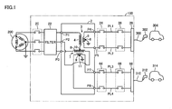
- Fig. 1 is an overall configuration diagram of a vehicular power supply apparatus according to a first embodiment of the present invention.
- a vehicular power supply apparatus 100 includes a Scott transformer 2, interrupters 20, 24 and 64, a filter 22, relays 26 and 66, and output ports 28 and 68.
- Scott transformer 2 includes a Teaser transformer 3 and a Main transformer 7.
- Teaser transformer 3 is configured by a primary winding 4 and a secondary winding 5.
- Main transformer 7 is configured by a primary winding 8 and a secondary winding 9.
- One end of primary winding 4 of Teaser transformer 3 is connected to a port P1 connected to the U phase of a three-phase AC power source 200.
- the other end of primary winding 4 is connected to a neutral point 10 of primary winding 8 of Main transformer 7.
- Secondary winding 5 of Teaser transformer 3 is connected to ports P4 and P5, and a neutral point 6 of secondary winding 5 is grounded.
- Primary winding 8 of Main transformer 7 is connected to a port P2 connected to the V phase of three-phase AC power source 200 and a port P3 connected to the W phase of three-phase AC power source 200.
- Secondary winding 9 of Main transformer 7 is connected to ports P7 and P8, and a neutral point 11 of secondary winding 9 is grounded.
- This Scott transformer 2 converts three-phase AC power from three-phase AC power source 200 inputted from ports P1 to P3 into single-phase AC power of two systems. Then, first single-phase AC power generated by Teaser transformer 3 is outputted from ports P4 and P5, and second single-phase AC power generated by Main transformer 7 is outputted from ports P7 and P8. Voltages of the first and second single-phase AC powers are set in accordance with vehicles 304 and 314 that receive power supply from vehicular power supply apparatus 100, and are 200 V, for example.
- Three-phase AC power source 200 supplies three-phase AC power to vehicular power supply apparatus 100.
- three-phase AC power source 200 is a power source that can absorb the power imbalance among the three phases caused by the load imbalance when either vehicle 304 or vehicle 314 is only connected to vehicular power supply apparatus 100, and is a commercial three-phase system power source, for example.
- Interrupter 20 is arranged at a three-phase power line between three-phase AC power source 200 and Scott transformer 2.
- Interrupter 20 is a ground-fault interrupter, for example, and electrically interrupts a power path between three-phase AC power source 200 and Scott transformer 2 when a not-shown zero-phase current detector (ZCT) detects electric leakage.
- Filter 22 is arranged at the three-phase power line between three-phase AC power source 200 and Scott transformer 2, and suppresses intrusion of noise from three-phase AC power source 200 to vehicular power supply apparatus 100 and leakage of noise from vehicular power supply apparatus 100 to three-phase AC power source 200.
- Filter 22 is configured, for example, by an EMI filter.
- Interrupter 24, power lines PL1 and PL2, relay 26, and output port 28 form a first output circuit that can supply power to vehicle 304 via a charging cable 300 connected to output port 28.
- Interrupter 24 is arranged between ports P4, P5 of Scott transformer 2 and power lines PL1, PL2.
- Interrupter 24 is also a ground-fault interrupter, for example, and electrically interrupts a power path between Scott transformer 2 and the first output circuit when the not-shown zero-phase current detector (ZCT) detects electric leakage.
- ZCT zero-phase current detector
- Relay 26 is arranged between power lines PL1, PL2 and output port 28.
- relay 26 When a prescribed power supply condition for permitting power supply from vehicular power supply apparatus 100 to vehicle 304 is satisfied, relay 26 is turned on and power supply from output port 28 to vehicle 304 becomes possible.
- Output port 28 is a power output unit for outputting, to vehicle 304, the single-phase AC power outputted from ports P4 and P5 of Scott transformer 2.
- charging cable 300 is connected to output port 28, and by connecting a charging connector 302 provided at a tip of charging cable 300 to a charging inlet of vehicle 304, power is supplied from vehicular power supply apparatus 100 to vehicle 304.
- a plug provided at a tip of a charging cord that is extendible from vehicle 304 may be connected to output port 28.
- interrupter 64 power lines PL3 and PL4, relay 66, and output port 68 form a second output circuit that can supply power to vehicle 314 via a charging cable 310 connected to output port 68.
- Interrupter 64 is arranged between ports P7, P8 of Scott transformer 2 and power lines PL3, PL4.
- Interrupter 64 is also a ground-fault interrupter, for example, and electrically interrupts a power path between Scott transformer 2 and the second output circuit when the not-shown zero-phase current detector (ZCT) detects electric leakage.
- ZCT zero-phase current detector
- Relay 66 is arranged between power lines PL3, PL4 and output port 68. When a prescribed power supply condition is satisfied, relay 66 is turned on and power supply from output port 68 to vehicle 314 becomes possible.
- Output port 68 is a power output unit for outputting, to vehicle 314, the single-phase AC power outputted from ports P7 and P8 of Scott transformer 2.
- charging cable 310 is connected to output port 68, and by connecting a charging connector 312 provided at a tip of charging cable 310 to a charging inlet of vehicle 314, power is supplied from vehicular power supply apparatus 100 to vehicle 314.
- a plug provided at a tip of a charging cord that is extendible from vehicle 314 may be connected to output port 68.
- vehicular power supply apparatus 100 converts the three-phase AC power supplied from three-phase AC power source 200 into the single-phase AC power of two systems by Scott transformer 2.
- Vehicular power supply apparatus 100 has output ports 28 and 68, and can simultaneously supply power to two vehicles 304 and 314.
- Scott transformer 2 is used, and thus, the capacity for one vehicle can be increased as compared with the case of using the three-phase three-wire transformer.
- the capacity is restricted to up to one third of the rated capacity of the three-phase three-wire transformer at the time of charging only one vehicle.
- three-phase AC power source 200 is a power source that can absorb the power imbalance among the three phases caused by the load imbalance when only one vehicle is connected to vehicular power supply apparatus 100.
- a power source having the limited capacity such as an emergency generator
- problems such as an influence of armature reaction and variations in output voltage in the generator used as the three-phase AC power source.
- this second embodiment describes such a configuration that the power balance among the three phases can be kept when the power source having the limited capacity is used as the three-phase AC power source.
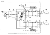
- Fig. 2 is an overall configuration diagram of a vehicular power supply apparatus according to the second embodiment.
- this vehicular power supply apparatus 100A is different from the configuration of vehicular power supply apparatus 100 according to the first embodiment as shown in Fig. 1 in that vehicular power supply apparatus 100A further includes detection units 30 and 70, and an ECU (Electronic Control Unit) 90.
- ECU Electronic Control Unit
- Detection unit 30 detects a voltage between power lines PL1 and PL2 and a current flowing through power lines PL1 and PL2, i.e., a voltage and a current of power supplied to vehicle 304 connected to output port 28, and outputs the detected values to ECU 90.
- Detection unit 70 detects a voltage between power lines PL3 and PL4 and a current flowing through power lines PL3 and PL4, i.e., a voltage and a current of power supplied to vehicle 314 connected to output port 68, and outputs the detected values to ECU 90.
- ECU 90 executes power control for supplying power from vehicular power supply apparatus 100A to vehicles 304 and 314 by software processing by a CPU (Central Processing Unit) executing the program stored in advance and/or by hardware processing by a dedicated electronic circuit. Specifically, ECU 90 generates power command values for vehicles 304 and 314 such that the power supplied to vehicle 304 connected to output port 28 becomes equal to the power supplied to vehicle 314 connected to output port 68, and outputs the generated power command values to vehicles 304 and 314.
- a CPU Central Processing Unit
- PLC power line communication
- SAE J1772 SAE Electric Vehicle Conductive Charge Coupler
- a three-phase AC power source 200A supplies three-phase AC power to vehicular power supply apparatus 100A.
- three-phase AC power source 200A is a power source having the limited capacity, which cannot absorb the power imbalance among the three phases caused by the load imbalance when either vehicle 304 or vehicle 314 is only connected to vehicular power supply apparatus 100A, and is an emergency generator or the like used at the time of a power failure in the commercial system power source, for example.
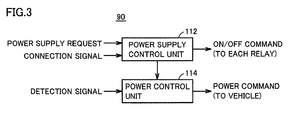
- Fig. 3 is a functional block diagram of ECU 90 shown in Fig. 2 .
- ECU 90 includes a power supply control unit 112 and a power control unit 114.
- Power supply control unit 112 receives a connection signal indicating the connection state between charging connector 302 of charging cable 300 and vehicle 304 as well as a connection signal indicating the connection state between charging connector 312 of charging cable 310 and vehicle 314.
- power control unit 112 Upon receiving a request for power supply from vehicular power supply apparatus 100A to vehicles 304 and 314 when charging connectors 302 and 312 are connected to vehicles 304 and 314, respectively, power control unit 112 outputs commands for turning on relays 26 and 66 to relays 26 and 66 and outputs a command to execute the power control to power control unit 114.
- relays 26 and 66 When relays 26 and 66 are turned on, power supply from output ports 28 and 68 to vehicles 304 and 314 becomes possible.
- Power control unit 114 receives current and voltage detection signals from each of detection units 30 and 70, and calculates the power supplied to vehicle 304 connected to output port 28 and the power supplied to vehicle 314 connected to output port 68, based on the detection signals. Upon receiving the command to execute the power control from power supply control unit 112, power control unit 114 generates the power command values for vehicles 304 and 314 such that the power supplied to vehicle 304 becomes equal to the power supplied to vehicle 314, and outputs the power command values to vehicles 304 and 314.
- Fig. 4 is an overall block diagram schematically showing a configuration of vehicle 304 (314) shown in Fig. 2 .
- vehicle 304 (314) includes a power storage device 410, a system main relay (hereinafter referred to as "SMR") 415, a PCU (Power Control Unit) 420, a motor generator 425, and a driving wheel 430.
- SMR system main relay
- PCU Power Control Unit
- Vehicle 304 (314) further includes a charging inlet 440, a charger 445, an SMR 450, and a PM-ECU 455.
- Power storage device 410 is a DC power source that stores power for running, and is configured, for example, by a nickel-metal hydride secondary battery, a lithium-ion secondary battery and the like. Power storage device 410 is charged by vehicular power supply apparatus 100A by using charger 445. At the time of braking of vehicle 304 (314) or reducing the acceleration on a downhill slope, power storage device 410 is also charged by receiving power generated by motor generator 425 from PCU 420. Power storage device 410 then outputs the stored power to PCU 420. Instead of the secondary battery, a large-capacitance capacitor can also be used as power storage device 410.
- SMR 415 is provided between power storage device 410 and PCU 420. SMR 415 is turned on when a vehicle system is started to cause vehicle 304 (314) to run, and is turned off when power storage device 410 is charged by charger 445.
- PCU 420 receives power supply from power storage device 410 and drives motor generator 425. At the time of braking of vehicle 304 (314) and the like, PCU 420 converts a voltage of the power generated by motor generator 425 that receives kinetic energy from driving wheel 430, and outputs the power to power storage device 410.
- PCU 420 is configured, for example, by a three-phase PWM inverter including switching elements for the three phases.
- a boost converter may be provided between the three-phase PWM inverter and power storage device 410.
- Motor generator 425 is a motor generator that can operate in a power running mode and in a regenerative mode, and is configured, for example, by a three-phase AC synchronous motor generator including a rotor having a permanent magnet embedded therein. Motor generator 425 is driven by PCU 420, generates driving torque for running and drives driving wheel 430. At the time of braking of vehicle 304 (314) and the like, motor generator 425 receives the kinetic energy of vehicle 304 (314) from driving wheel 430 and generates power.
- Charging inlet 440 is configured to be fittable into charging connector 302 (312) on the vehicular power supply apparatus 100A side. Charging inlet 440 receives power supplied from vehicular power supply apparatus 100A and outputs the power to charger 445. Instead of charging inlet 440, a charging plug configured to be connectable to an electrical outlet of vehicular power supply apparatus 100A may be provided.
- Charger 445 is configured to receive the power from vehicular power supply apparatus 100A and charge power storage device 410. Specifically, based on a control signal from PM-ECU 455, charger 445 converts the power supplied from vehicular power supply apparatus 100A into charging power for power storage device 410.
- a charging relay 450 is provided between charger 445 and power lines PL7, PL8 arranged between power storage device 410 and SMR 415. Charging relay 450 is turned on when power storage device 410 is charged by vehicular power supply apparatus 100A (hereinafter also referred to as "external charging”), and is turned off when external charging is finished.
- PM-ECU 455 controls the operation of charger 445 by software processing by a CPU executing the program stored in advance and/or by hardware processing by a dedicated electronic circuit. Specifically, at the time of external charging, PM-ECU 455 generates a control signal for operating charger 445 such that power storage device 410 is charged by vehicular power supply apparatus 100A in accordance with the power command value received from vehicular power supply apparatus 100A, and outputs the generated control signal to charger 445.
- power line communication via charging cable 300 may be used, or a pilot signal based on a control pilot circuit conforming to SAE J1772 (SAE Electric Vehicle Conductive Charge Coupler) in the United States of America or JEVS G 109 in Japan may be used, or wireless communication may be used.
- SAE J1772 SAE Electric Vehicle Conductive Charge Coupler
- detection units 30 and 70 are provided, and the power command values are generated by ECU 90 based on the detected values and are outputted to vehicles 304 and 314.
- ECU 90 generates the power command values such that the power supplied to vehicle 304 becomes equal to the power supplied to vehicle 314. Therefore, according to this second embodiment, even in the case of using three-phase AC power source 200A that cannot absorb the power imbalance among the three phases caused by the load imbalance, high-power charging is possible and the power balance in three-phase AC power source 200A can be maintained.
- This third embodiment describes such a configuration that power can be supplied to a plurality of vehicles from each output system of a Scott transformer (each of a circuit that receives an output from ports P4 and P5 and a circuit that receives an output from ports P7 and P8), while keeping the power balance in a three-phase AC power source.
- a Scott transformer each of a circuit that receives an output from ports P4 and P5 and a circuit that receives an output from ports P7 and P8
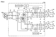
- Fig. 5 is an overall configuration diagram of a vehicular power supply apparatus according to the third embodiment.
- This Fig. 5 typically shows such a configuration that power can be supplied to two vehicles from each output system of the Scott transformer.
- this vehicular power supply apparatus 100B is different from the configuration of vehicular power supply apparatus 100A according to the second embodiment as shown in Fig. 2 in that vehicular power supply apparatus 100B further includes relays 27 and 67, output ports 29 and 69, and a notification unit 92, and includes detection units 30A and 70A and an ECU 90A instead of detection units 30 and 70 and ECU 90.
- Relay 27 is arranged between power lines PL1, PL2 and output port 29. When a prescribed power supply condition for permitting power supply from vehicular power supply apparatus 100B to a vehicle 324 is satisfied, relay 27 is turned on and power supply from output port 29 to vehicle 324 becomes possible.
- Output port 29 is a power output unit for outputting, to vehicle 324, single-phase AC power outputted from ports P4 and P5 of Scott transformer 2.
- Relay 67 is arranged between power lines PL3, PL4 and output port 69. When a prescribed power supply condition is satisfied, relay 67 is turned on and power supply from output port 69 to vehicle 334 becomes possible.
- Output port 69 is a power output unit for outputting, to vehicle 334, single-phase AC power outputted from ports P7 and P8 of Scott transformer 2.
- Detection unit 30A detects a voltage between power lines PL1 and PL2 and a current flowing to output ports 28 and 29, i.e., a voltage and a current of power supplied from vehicular power supply apparatus 100B to each of vehicles 304 and 324, and outputs the detected values to ECU 90A.
- Detection unit 70A detects a voltage between power lines PL3 and PL4 and a current flowing to output ports 68 and 69, i.e., a voltage and a current of power supplied from vehicular power supply apparatus 100B to each of vehicles 314 and 334, and outputs the detected values to ECU 90A.
- ECU 90A executes power control for supplying power from vehicular power supply apparatus 100B to vehicles 304, 314, 324, and 334. Specifically, ECU 90A generates power command values for vehicles 304, 314, 324, and 334 such that the sum of the power supplied to vehicles 304 and 324 connected to output ports 28 and 29, respectively, becomes equal to the sum of the power supplied to vehicles 314 and 334 connected to output ports 68 and 69, respectively, and outputs the generated power command values to vehicles 304, 314, 324, and 334.
- All of vehicles 304, 314, 324, and 334 do not necessarily need to be connected.
- the second vehicle is connected to an output system different from an output system to which the first vehicle is connected.
- the second vehicle is connected to either one of output ports 68 and 69.
- ECU 90A senses the connection situations of the vehicles to output ports 28, 29, 68, and 69, and generates a notification signal for encouraging the second vehicle to be connected to an output system different from an output system to which the first vehicle is connected, and outputs the notification signal to notification unit 92.
- ECU 90A senses the connection situation, and generates a notification signal for encouraging the second vehicle to be connected to either one of output ports 68 and 69, and outputs the notification signal to notification unit 92.
- notification unit 92 notifies a user of vehicular power supply apparatus 100B about which port the vehicle should be connected to.
- notification unit 92 is configured by an indicating lamp provided at each of output ports 28, 29, 68, and 69.
- notification unit 92 causes the indicating lamps provided at output ports 68 and 69 to illuminate in accordance with the notification signal received from ECU 90A.
- vehicular power supply apparatus 100B The remaining configuration of vehicular power supply apparatus 100B is as described with reference to Fig. 1 .
- Fig. 6 is a functional block diagram of ECU 90A shown in Fig. 5 .
- ECU 90A is different from the configuration of ECU 90 shown in Fig. 3 in that ECU 90A further includes a notification control unit 116, and includes a power control unit 114A instead of power control unit 114.
- Notification control unit 116 receives the connection situations of the vehicles to output ports 28, 29, 68, and 69 from power supply control unit 112. When one vehicle is connected to any one of output ports 28, 29, 68, and 69, notification control unit 116 generates the notification signal for encouraging the second vehicle to be connected to an output port of an output system different from the output system to which the first vehicle is connected, and outputs the notification signal to notification unit 92.
- Power control unit 114A receives current and voltage detection signals from each of detection units 30A and 70A. Based on these detection signals, power control unit 114A calculates first power supplied to vehicle 304 connected to output port 28, second power supplied to vehicle 324 connected to output port 29, third power supplied to vehicle 314 connected to output port 68, and fourth power supplied to vehicle 334 connected to output port 69. When no vehicle is connected to any output port, a current is zero, and thus, the power is calculated as zero.
- power control unit 114A Upon receiving the command to execute the power control from power supply control unit 112, power control unit 114A generates power command values for the respective vehicles such that the sum of the first and second powers becomes equal to the sum of the third and fourth powers, and outputs the power command values to the vehicles connected to the output ports.
- notification unit 92 is provided for encouraging the second vehicle to be connected to an output port of an output system different from the output system to which the first vehicle is connected, and thus, the power imbalance caused by concentration of a plurality of vehicles on one output system is prevented. Therefore, according to this third embodiment, power can be supplied to the larger number of vehicles while maintaining the power balance in three-phase AC power source 200A.
- This fourth embodiment describes such a configuration that a vehicular power supply apparatus can also be used as a commercial power source (e.g., power source of AC 100 V).
- a commercial power source e.g., power source of AC 100 V.
- Fig. 7 is an overall configuration diagram of a vehicular power supply apparatus according to the fourth embodiment.
- this vehicular power supply apparatus 100C includes a Scott transformer 2A, interrupters 20, 24A and 64A, filter 22, switching relays 40 and 80, relays 26A, 26B, 66A, and 66B, output ports 28 and 68, and electrical outlets 44, 46, 84, and 86.
- Vehicular power supply apparatus 100C further includes detection units 30B and 70B, and an ECU 90B.
- Scott transformer 2A is different from the configuration of Scott transformer 2 shown in Fig. 1 in that Scott transformer 2A further includes ports P6 and P9. Port P6 is connected to neutral point 6 of secondary winding 5 of Teaser transformer 3. Port P9 is connected to neutral point 11 of secondary winding 9 of Main transformer 7.
- Interrupter 24A is different from the configuration of interrupter 24 shown in Fig. 1 in that interrupter 24A is configured to be capable of further interrupting a power path between port P6 and switching relay 40.
- Switching relay 40 is arranged between port P6 and a power line PL5. Switching relay 40 is turned on when use of electrical outlets 44 and 46 is requested, and is turned off when electrical outlets 44 and 46 are not used.
- Relay 26A is arranged between power lines PL1, PL5 and electrical outlet 44.
- Relay 26B is arranged between power lines PL2, PL5 and electrical outlet 46.
- Electrical outlets 44 and 46 are configured such that a power source plug of home electric appliances and the like can fit thereinto.
- Output port 28 is connected to power lines PL1 and PL2 via relays 26A and 26B.
- relays 26A and 26B are turned on and use of electrical outlets 44 and 46 becomes possible.
- a relay RY1 in relay 26A and a relay RY2 in relay 26B are turned on.
- Interrupter 64A is different from the configuration of interrupter 64 shown in Fig. 1 in that interrupter 64A is configured to be capable of further interrupting a power path between port P9 and switching relay 80.
- Switching relay 80 is arranged between port P9 and power line PL6. Switching relay 80 is turned on when use of electrical outlets 84 and 86 is requested, and is turned off when electrical outlets 84 and 86 are not used.
- Relay 66A is arranged between power lines PL3, PL6 and electrical outlet 86.
- Relay 66B is arranged between power lines PL4, PL6 and electrical outlet 84.
- Electrical outlets 84 and 86 are configured such that a power source plug of home electric appliances and the like can fit thereinto.
- Output port 68 is connected to power lines PL3 and PL4 via relays 66A and 66B. When a prescribed condition for permitting output from electrical outlets 84 and 86 is satisfied, relays 66A and 66B are turned on and use of electrical outlets 84 and 86 becomes possible. At the time of power supply to vehicle 314, a relay RY3 in relay 66A and a relay RY4 in relay 66B are turned on.
- detection unit 30B detects a voltage and a current supplied to output port 28, and outputs the detected values to ECU 90B.
- detection unit 30B detects a voltage and a current supplied to electrical outlets 44 and 46, and outputs the detected values to ECU 90B.
- detection unit 70B detects a voltage and a current supplied to output port 68, and outputs the detected values to ECU 90B.
- detection unit 30B detects a voltage and a current supplied to electrical outlets 84 and 86, and outputs the detected values to ECU 90B.
- ECU 90B turns on relay RY1 in relay 26A and relay RY2 in relay 26B.
- ECU 90B turns on relays 26A and 26B.
- ECU 90B turns on relay RY3 in relay 66A and relay RY4 in relay 66B.
- ECU 90B turns on relays 66A and 66B.
- Relays 26A, 26B, 66A, and 66B described above have been used in common both at the time of power supply to vehicles 304 and 314 and at the time of use of electrical outlets 44, 46, 84, and 86.
- a relay provided at a path for power supply to a vehicle and a relay provided at a path for power supply to an electrical outlet may be configured completely separately.
- the commercial power source e.g., power source of AC 100 V
- the commercial power source can be obtained from vehicular power supply apparatus 100C, and thus, user's convenience is improved.
- This fifth embodiment describes a DC chargeable configuration.
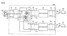
- Fig. 8 is an overall configuration diagram of a vehicular power supply apparatus according to the fifth embodiment. Referring to Fig. 8 , this vehicular power supply apparatus 100D is different from the configuration of vehicular power supply apparatus 100 according to the first embodiment as shown in Fig. 1 in that vehicular power supply apparatus 100D further includes rectification circuits 94 and 96.
- Rectification circuit 94 is arranged between interrupter 24 and relay 26. Rectification circuit 94 rectifies single-phase AC power outputted from ports P4 and P5 of Scott transformer 2 into DC power, and outputs the DC power to output port 28. Rectification circuit 96 is arranged between interrupter 64 and relay 66. Rectification circuit 96 rectifies single-phase AC power outputted from ports P7 and P8 of Scott transformer 2 into DC power, and outputs the DC power to output port 68.
- rectification circuits 94 and 96 may be included.
- switching between AC charging and DC charging may be made by providing a circuit that bypasses rectification circuits 94 and 96 to allow switching between use and disuse of rectification circuits 94 and 96.
- a vehicular power supply apparatus that can also be adapted to high-power charging such as DC quick charging.
- output ports 28 and 68 correspond to one example of "first output unit” and “second output unit” in the present invention, respectively
- ECU 90, 90A, 90B corresponds to one example of "control device” in the present invention
- output ports 29 and 69 correspond to one example of "third output unit” and “fourth output unit” in the present invention, respectively.
Landscapes
- Engineering & Computer Science (AREA)
- Power Engineering (AREA)
- Transportation (AREA)
- Mechanical Engineering (AREA)
- Charge And Discharge Circuits For Batteries Or The Like (AREA)
- Electric Propulsion And Braking For Vehicles (AREA)
Abstract
Description
- The present invention relates to a vehicular power supply apparatus, and particularly to a vehicular power supply apparatus capable of converting three-phase AC power supplied from a three-phase AC power source into single-phase AC power and supplying the single-phase AC power to a vehicle.
- Japanese Patent Laying-Open No.
4-340330 -
- PTD 1: Japanese Patent Laying-Open No.
4-340330 - PTD 2: Japanese Patent Laying-Open No.
2001-231169 - When a power supply apparatus is configured to be capable of simultaneously charging a plurality of vehicles by one AC power source, the use of a single-phase AC power source is not realistic. This is because the capacity of a single-phase transformer that converts single-phase AC power into DC power is generally about 20 k to 30 kVA, and thus, when the single-phase AC power source is used as a power source for a vehicle that requires high-power charging (particularly at the time of quick charging), the capacity is restricted to the capacity for approximately one output (one vehicle).
- Large-capacity (e.g., 50 kVA or more) power conversion is required to allow simultaneous charging of a plurality of vehicles by one AC power source, and thus, the power source is limited to a three-phase AC power source. In this case, however, if a single-phase transformer is formed for each phase and output circuits for three outputs (three vehicles) are formed by using a three-phase three-wire transformer, only up to one third of the transformer capacity can be used for one output circuit at the time of charging only one vehicle, which is insufficient for vehicle charging that requires high-power charging.
- Thus, the present invention has been made to solve the aforementioned problem, and an object thereof is to provide a vehicular power supply apparatus that can be adapted to high-power charging as well.
- According to the present invention, a vehicular power supply apparatus is a vehicular power supply apparatus capable of converting three-phase AC power supplied from a three-phase AC power source into single-phase AC power and supplying the single-phase AC power to a vehicle, the vehicular power supply apparatus including: a Scott transformer; and first and second output units. The Scott transformer is configured to convert the three-phase AC power into first and second single-phase AC powers. The first output unit is for supplying the first single-phase AC power to a first vehicle. The second output unit is for supplying the second single-phase AC power to a second vehicle.
- Preferably, the vehicular power supply apparatus further includes: a detection unit for detecting the first and second single-phase AC powers; and a control device. The control device executes power control such that the first and second single-phase AC powers become equal to each other, based on a detected value of the detection unit.
- More preferably, the control device generates first and second power command values equalized each other, and outputs the first and second power command values to the first vehicle connected to the first output unit and the second vehicle connected to the second output unit, respectively. The first and second vehicles execute charging control in accordance with the first and second power command values, respectively.
- Preferably, the vehicular power supply apparatus further includes: a third output unit connected in parallel to the first output unit; and a fourth output unit connected in parallel to the second output unit. The control device executes the power control such that a sum of power outputted from the first and third output units becomes equal to a sum of power outputted from the second and fourth output units.
- More preferably, the vehicular power supply apparatus further includes a notification unit. The notification unit is for encouraging another vehicle to be connected to either one of the second and fourth output units when the vehicle is connected to either one of the first and third output units.
- Preferably, the vehicular power supply apparatus further includes an output circuit for taking out commercial power from the Scott transformer.
- More preferably, the output circuit is configured by a power line connected to a neutral point of a secondary winding of the Scott transformer, and an output line of the Scott transformer.
- Preferably, the vehicular power supply apparatus further includes a rectification circuit for converting the first single-phase AC power into DC power and supplying the DC power from the first output unit to the first vehicle.
- In the present invention, the three-phase AC power supplied from the three-phase AC power source is converted into the first and second single-phase AC powers by the Scott transformer, and the first and second single-phase AC powers are supplied from the first and second output units to the first and second vehicles, respectively. As a result, up to one half of the transformer capacity can be used for one output circuit at the time of charging only one vehicle. Therefore, according to the present invention, there can be provided a vehicular power supply apparatus that can be adapted to high-power charging as well.
-
-
Fig. 1 is an overall configuration diagram of a vehicular power supply apparatus according to a first embodiment of the present invention. -
Fig. 2 is an overall configuration diagram of a vehicular power supply apparatus according to a second embodiment. -
Fig. 3 is a functional block diagram of an ECU shown inFig. 2 . -
Fig. 4 is an overall block diagram schematically showing a configuration of a vehicle shown inFig. 2 . -
Fig. 5 is an overall configuration diagram of a vehicular power supply apparatus according to a third embodiment. -
Fig. 6 is a functional block diagram of an ECU shown inFig. 5 . -
Fig. 7 is an overall configuration diagram of a vehicular power supply apparatus according to a fourth embodiment. -
Fig. 8 is an overall configuration diagram of a vehicular power supply apparatus according to a fifth embodiment. - Embodiments of the present invention will be described in detail hereinafter with reference to the drawings, in which the same or corresponding portions are denoted by the same reference characters and description thereof will not be repeated.
-
Fig. 1 is an overall configuration diagram of a vehicular power supply apparatus according to a first embodiment of the present invention. Referring toFig. 1 , a vehicularpower supply apparatus 100 includes a Scotttransformer 2,interrupters filter 22,relays output ports - Scott
transformer 2 includes aTeaser transformer 3 and a Main transformer 7.Teaser transformer 3 is configured by aprimary winding 4 and asecondary winding 5. Main transformer 7 is configured by a primary winding 8 and a secondary winding 9. One end ofprimary winding 4 of Teasertransformer 3 is connected to a port P1 connected to the U phase of a three-phaseAC power source 200. The other end ofprimary winding 4 is connected to a neutral point 10 of primary winding 8 of Main transformer 7.Secondary winding 5 ofTeaser transformer 3 is connected to ports P4 and P5, and a neutral point 6 ofsecondary winding 5 is grounded. Primary winding 8 of Main transformer 7 is connected to a port P2 connected to the V phase of three-phaseAC power source 200 and a port P3 connected to the W phase of three-phaseAC power source 200. Secondary winding 9 of Main transformer 7 is connected to ports P7 and P8, and aneutral point 11 of secondary winding 9 is grounded. - This Scott transformer 2 converts three-phase AC power from three-phase
AC power source 200 inputted from ports P1 to P3 into single-phase AC power of two systems. Then, first single-phase AC power generated by Teasertransformer 3 is outputted from ports P4 and P5, and second single-phase AC power generated by Main transformer 7 is outputted from ports P7 and P8. Voltages of the first and second single-phase AC powers are set in accordance withvehicles power supply apparatus 100, and are 200 V, for example. - Three-phase
AC power source 200 supplies three-phase AC power to vehicularpower supply apparatus 100. In this first embodiment, three-phaseAC power source 200 is a power source that can absorb the power imbalance among the three phases caused by the load imbalance when eithervehicle 304 orvehicle 314 is only connected to vehicularpower supply apparatus 100, and is a commercial three-phase system power source, for example. -
Interrupter 20 is arranged at a three-phase power line between three-phaseAC power source 200 and Scotttransformer 2.Interrupter 20 is a ground-fault interrupter, for example, and electrically interrupts a power path between three-phaseAC power source 200 and Scott transformer 2 when a not-shown zero-phase current detector (ZCT) detects electric leakage.Filter 22 is arranged at the three-phase power line between three-phaseAC power source 200 and Scotttransformer 2, and suppresses intrusion of noise from three-phaseAC power source 200 to vehicularpower supply apparatus 100 and leakage of noise from vehicularpower supply apparatus 100 to three-phaseAC power source 200.Filter 22 is configured, for example, by an EMI filter. -
Interrupter 24, power lines PL1 and PL2,relay 26, andoutput port 28 form a first output circuit that can supply power tovehicle 304 via a chargingcable 300 connected tooutput port 28.Interrupter 24 is arranged between ports P4, P5 ofScott transformer 2 and power lines PL1, PL2.Interrupter 24 is also a ground-fault interrupter, for example, and electrically interrupts a power path betweenScott transformer 2 and the first output circuit when the not-shown zero-phase current detector (ZCT) detects electric leakage. -
Relay 26 is arranged between power lines PL1, PL2 andoutput port 28. When a prescribed power supply condition for permitting power supply from vehicularpower supply apparatus 100 tovehicle 304 is satisfied,relay 26 is turned on and power supply fromoutput port 28 tovehicle 304 becomes possible.Output port 28 is a power output unit for outputting, tovehicle 304, the single-phase AC power outputted from ports P4 and P5 ofScott transformer 2. By way of example, chargingcable 300 is connected tooutput port 28, and by connecting a chargingconnector 302 provided at a tip of chargingcable 300 to a charging inlet ofvehicle 304, power is supplied from vehicularpower supply apparatus 100 tovehicle 304. A plug provided at a tip of a charging cord that is extendible fromvehicle 304 may be connected tooutput port 28. - In addition,
interrupter 64, power lines PL3 and PL4,relay 66, andoutput port 68 form a second output circuit that can supply power tovehicle 314 via a chargingcable 310 connected tooutput port 68.Interrupter 64 is arranged between ports P7, P8 ofScott transformer 2 and power lines PL3, PL4.Interrupter 64 is also a ground-fault interrupter, for example, and electrically interrupts a power path betweenScott transformer 2 and the second output circuit when the not-shown zero-phase current detector (ZCT) detects electric leakage. -
Relay 66 is arranged between power lines PL3, PL4 andoutput port 68. When a prescribed power supply condition is satisfied,relay 66 is turned on and power supply fromoutput port 68 tovehicle 314 becomes possible.Output port 68 is a power output unit for outputting, tovehicle 314, the single-phase AC power outputted from ports P7 and P8 ofScott transformer 2. By way of example, chargingcable 310 is connected tooutput port 68, and by connecting a chargingconnector 312 provided at a tip of chargingcable 310 to a charging inlet ofvehicle 314, power is supplied from vehicularpower supply apparatus 100 tovehicle 314. A plug provided at a tip of a charging cord that is extendible fromvehicle 314 may be connected tooutput port 68. - In this first embodiment, vehicular
power supply apparatus 100 converts the three-phase AC power supplied from three-phaseAC power source 200 into the single-phase AC power of two systems byScott transformer 2. Vehicularpower supply apparatus 100 hasoutput ports vehicles power supply apparatus 100,Scott transformer 2 is used, and thus, the capacity for one vehicle can be increased as compared with the case of using the three-phase three-wire transformer. Specifically, in the case of using the three-phase three-wire transformer, the capacity is restricted to up to one third of the rated capacity of the three-phase three-wire transformer at the time of charging only one vehicle. In this vehicularpower supply apparatus 100, however,Scott transformer 2 is used, and thus, up to one half of the rated capacity ofScott transformer 2 can be used at the time of charging only one vehicle. Therefore, according to this first embodiment, there can be realized a vehicular power supply apparatus that can also be adapted to high-power charging such as quick charging. - In the first embodiment, three-phase
AC power source 200 is a power source that can absorb the power imbalance among the three phases caused by the load imbalance when only one vehicle is connected to vehicularpower supply apparatus 100. However, if the aforementioned power imbalance among the three phases occurs when a power source having the limited capacity such as an emergency generator is used as the three-phase AC power source that supplies power to the vehicular power supply apparatus, there arise problems such as an influence of armature reaction and variations in output voltage in the generator used as the three-phase AC power source. Thus, this second embodiment describes such a configuration that the power balance among the three phases can be kept when the power source having the limited capacity is used as the three-phase AC power source. -
Fig. 2 is an overall configuration diagram of a vehicular power supply apparatus according to the second embodiment. Referring toFig. 2 , this vehicularpower supply apparatus 100A is different from the configuration of vehicularpower supply apparatus 100 according to the first embodiment as shown inFig. 1 in that vehicularpower supply apparatus 100A further includesdetection units -
Detection unit 30 detects a voltage between power lines PL1 and PL2 and a current flowing through power lines PL1 and PL2, i.e., a voltage and a current of power supplied tovehicle 304 connected tooutput port 28, and outputs the detected values toECU 90.Detection unit 70 detects a voltage between power lines PL3 and PL4 and a current flowing through power lines PL3 and PL4, i.e., a voltage and a current of power supplied tovehicle 314 connected tooutput port 68, and outputs the detected values toECU 90. -
ECU 90 executes power control for supplying power from vehicularpower supply apparatus 100A tovehicles ECU 90 generates power command values forvehicles vehicle 304 connected tooutput port 28 becomes equal to the power supplied tovehicle 314 connected tooutput port 68, and outputs the generated power command values tovehicles - As communication means for outputting the power command values from
ECU 90 tovehicles cables - A three-phase
AC power source 200A supplies three-phase AC power to vehicularpower supply apparatus 100A. In this second embodiment, three-phaseAC power source 200A is a power source having the limited capacity, which cannot absorb the power imbalance among the three phases caused by the load imbalance when eithervehicle 304 orvehicle 314 is only connected to vehicularpower supply apparatus 100A, and is an emergency generator or the like used at the time of a power failure in the commercial system power source, for example. -
Fig. 3 is a functional block diagram ofECU 90 shown inFig. 2 . Referring toFig. 2 together withFig. 3 ,ECU 90 includes a powersupply control unit 112 and apower control unit 114. Powersupply control unit 112 receives a connection signal indicating the connection state between chargingconnector 302 of chargingcable 300 andvehicle 304 as well as a connection signal indicating the connection state between chargingconnector 312 of chargingcable 310 andvehicle 314. Upon receiving a request for power supply from vehicularpower supply apparatus 100A tovehicles connectors vehicles power control unit 112 outputs commands for turning on relays 26 and 66 torelays power control unit 114. When relays 26 and 66 are turned on, power supply fromoutput ports vehicles -
Power control unit 114 receives current and voltage detection signals from each ofdetection units vehicle 304 connected tooutput port 28 and the power supplied tovehicle 314 connected tooutput port 68, based on the detection signals. Upon receiving the command to execute the power control from powersupply control unit 112,power control unit 114 generates the power command values forvehicles vehicle 304 becomes equal to the power supplied tovehicle 314, and outputs the power command values tovehicles -
Fig. 4 is an overall block diagram schematically showing a configuration of vehicle 304 (314) shown inFig. 2 . Referring toFig. 4 , vehicle 304 (314) includes apower storage device 410, a system main relay (hereinafter referred to as "SMR") 415, a PCU (Power Control Unit) 420, amotor generator 425, and adriving wheel 430. Vehicle 304 (314) further includes a charginginlet 440, acharger 445, anSMR 450, and a PM-ECU 455. -
Power storage device 410 is a DC power source that stores power for running, and is configured, for example, by a nickel-metal hydride secondary battery, a lithium-ion secondary battery and the like.Power storage device 410 is charged by vehicularpower supply apparatus 100A by usingcharger 445. At the time of braking of vehicle 304 (314) or reducing the acceleration on a downhill slope,power storage device 410 is also charged by receiving power generated bymotor generator 425 fromPCU 420.Power storage device 410 then outputs the stored power toPCU 420. Instead of the secondary battery, a large-capacitance capacitor can also be used aspower storage device 410. -
SMR 415 is provided betweenpower storage device 410 andPCU 420.SMR 415 is turned on when a vehicle system is started to cause vehicle 304 (314) to run, and is turned off whenpower storage device 410 is charged bycharger 445. -
PCU 420 receives power supply frompower storage device 410 and drivesmotor generator 425. At the time of braking of vehicle 304 (314) and the like,PCU 420 converts a voltage of the power generated bymotor generator 425 that receives kinetic energy from drivingwheel 430, and outputs the power topower storage device 410.PCU 420 is configured, for example, by a three-phase PWM inverter including switching elements for the three phases. A boost converter may be provided between the three-phase PWM inverter andpower storage device 410. -
Motor generator 425 is a motor generator that can operate in a power running mode and in a regenerative mode, and is configured, for example, by a three-phase AC synchronous motor generator including a rotor having a permanent magnet embedded therein.Motor generator 425 is driven byPCU 420, generates driving torque for running anddrives driving wheel 430. At the time of braking of vehicle 304 (314) and the like,motor generator 425 receives the kinetic energy of vehicle 304 (314) fromdriving wheel 430 and generates power. - Charging
inlet 440 is configured to be fittable into charging connector 302 (312) on the vehicularpower supply apparatus 100A side. Charginginlet 440 receives power supplied from vehicularpower supply apparatus 100A and outputs the power tocharger 445. Instead of charginginlet 440, a charging plug configured to be connectable to an electrical outlet of vehicularpower supply apparatus 100A may be provided. -
Charger 445 is configured to receive the power from vehicularpower supply apparatus 100A and chargepower storage device 410. Specifically, based on a control signal from PM-ECU 455,charger 445 converts the power supplied from vehicularpower supply apparatus 100A into charging power forpower storage device 410. A chargingrelay 450 is provided betweencharger 445 and power lines PL7, PL8 arranged betweenpower storage device 410 andSMR 415. Chargingrelay 450 is turned on whenpower storage device 410 is charged by vehicularpower supply apparatus 100A (hereinafter also referred to as "external charging"), and is turned off when external charging is finished. - PM-
ECU 455 controls the operation ofcharger 445 by software processing by a CPU executing the program stored in advance and/or by hardware processing by a dedicated electronic circuit. Specifically, at the time of external charging, PM-ECU 455 generates a control signal for operatingcharger 445 such thatpower storage device 410 is charged by vehicularpower supply apparatus 100A in accordance with the power command value received from vehicularpower supply apparatus 100A, and outputs the generated control signal tocharger 445. - As described above, as communication means for receiving the power command value from vehicular
power supply apparatus 100A, power line communication via charging cable 300 (310) may be used, or a pilot signal based on a control pilot circuit conforming to SAE J1772 (SAE Electric Vehicle Conductive Charge Coupler) in the United States of America or JEVS G 109 in Japan may be used, or wireless communication may be used. - As described above, in this second embodiment,
detection units ECU 90 based on the detected values and are outputted tovehicles ECU 90 generates the power command values such that the power supplied tovehicle 304 becomes equal to the power supplied tovehicle 314. Therefore, according to this second embodiment, even in the case of using three-phaseAC power source 200A that cannot absorb the power imbalance among the three phases caused by the load imbalance, high-power charging is possible and the power balance in three-phaseAC power source 200A can be maintained. - This third embodiment describes such a configuration that power can be supplied to a plurality of vehicles from each output system of a Scott transformer (each of a circuit that receives an output from ports P4 and P5 and a circuit that receives an output from ports P7 and P8), while keeping the power balance in a three-phase AC power source.
-
Fig. 5 is an overall configuration diagram of a vehicular power supply apparatus according to the third embodiment. ThisFig. 5 typically shows such a configuration that power can be supplied to two vehicles from each output system of the Scott transformer. Referring toFig. 5 , this vehicularpower supply apparatus 100B is different from the configuration of vehicularpower supply apparatus 100A according to the second embodiment as shown inFig. 2 in that vehicularpower supply apparatus 100B further includesrelays output ports notification unit 92, and includesdetection units ECU 90A instead ofdetection units ECU 90. -
Relay 27 is arranged between power lines PL1, PL2 andoutput port 29. When a prescribed power supply condition for permitting power supply from vehicularpower supply apparatus 100B to avehicle 324 is satisfied,relay 27 is turned on and power supply fromoutput port 29 tovehicle 324 becomes possible.Output port 29 is a power output unit for outputting, tovehicle 324, single-phase AC power outputted from ports P4 and P5 ofScott transformer 2. -
Relay 67 is arranged between power lines PL3, PL4 andoutput port 69. When a prescribed power supply condition is satisfied,relay 67 is turned on and power supply fromoutput port 69 tovehicle 334 becomes possible.Output port 69 is a power output unit for outputting, tovehicle 334, single-phase AC power outputted from ports P7 and P8 ofScott transformer 2. -
Detection unit 30A detects a voltage between power lines PL1 and PL2 and a current flowing tooutput ports power supply apparatus 100B to each ofvehicles ECU 90A.Detection unit 70A detects a voltage between power lines PL3 and PL4 and a current flowing tooutput ports power supply apparatus 100B to each ofvehicles ECU 90A. -
ECU 90A executes power control for supplying power from vehicularpower supply apparatus 100B tovehicles ECU 90A generates power command values forvehicles vehicles output ports vehicles output ports vehicles - All of
vehicles AC power source 200A, the second vehicle is connected to an output system different from an output system to which the first vehicle is connected. In other words, whenvehicle 304 is connected, for example, the second vehicle is connected to either one ofoutput ports - In order to encourage the aforementioned connection,
ECU 90A senses the connection situations of the vehicles tooutput ports notification unit 92. By way of example, whenonly vehicle 304 is connected to vehicularpower supply apparatus 100B,ECU 90A senses the connection situation, and generates a notification signal for encouraging the second vehicle to be connected to either one ofoutput ports notification unit 92. - In accordance with the notification signal received from
ECU 90A,notification unit 92 notifies a user of vehicularpower supply apparatus 100B about which port the vehicle should be connected to. By way of example,notification unit 92 is configured by an indicating lamp provided at each ofoutput ports vehicle 304 is connected to vehicularpower supply apparatus 100B, for example,notification unit 92 causes the indicating lamps provided atoutput ports ECU 90A. - The remaining configuration of vehicular
power supply apparatus 100B is as described with reference toFig. 1 . -
Fig. 6 is a functional block diagram ofECU 90A shown inFig. 5 . Referring toFig. 6 ,ECU 90A is different from the configuration ofECU 90 shown inFig. 3 in thatECU 90A further includes anotification control unit 116, and includes apower control unit 114A instead ofpower control unit 114. -
Notification control unit 116 receives the connection situations of the vehicles tooutput ports supply control unit 112. When one vehicle is connected to any one ofoutput ports notification control unit 116 generates the notification signal for encouraging the second vehicle to be connected to an output port of an output system different from the output system to which the first vehicle is connected, and outputs the notification signal tonotification unit 92. -
Power control unit 114A receives current and voltage detection signals from each ofdetection units power control unit 114A calculates first power supplied tovehicle 304 connected tooutput port 28, second power supplied tovehicle 324 connected tooutput port 29, third power supplied tovehicle 314 connected tooutput port 68, and fourth power supplied tovehicle 334 connected tooutput port 69. When no vehicle is connected to any output port, a current is zero, and thus, the power is calculated as zero. Upon receiving the command to execute the power control from powersupply control unit 112,power control unit 114A generates power command values for the respective vehicles such that the sum of the first and second powers becomes equal to the sum of the third and fourth powers, and outputs the power command values to the vehicles connected to the output ports. - As described above, in this third embodiment,
notification unit 92 is provided for encouraging the second vehicle to be connected to an output port of an output system different from the output system to which the first vehicle is connected, and thus, the power imbalance caused by concentration of a plurality of vehicles on one output system is prevented. Therefore, according to this third embodiment, power can be supplied to the larger number of vehicles while maintaining the power balance in three-phaseAC power source 200A. - This fourth embodiment describes such a configuration that a vehicular power supply apparatus can also be used as a commercial power source (e.g., power source of AC 100 V).
-
Fig. 7 is an overall configuration diagram of a vehicular power supply apparatus according to the fourth embodiment. Referring toFig. 7 , this vehicularpower supply apparatus 100C includes aScott transformer 2A,interrupters filter 22, switchingrelays output ports electrical outlets power supply apparatus 100C further includesdetection units ECU 90B. -
Scott transformer 2A is different from the configuration ofScott transformer 2 shown inFig. 1 in thatScott transformer 2A further includes ports P6 and P9. Port P6 is connected to neutral point 6 of secondary winding 5 ofTeaser transformer 3. Port P9 is connected toneutral point 11 of secondary winding 9 of Main transformer 7. -
Interrupter 24A is different from the configuration ofinterrupter 24 shown inFig. 1 in thatinterrupter 24A is configured to be capable of further interrupting a power path between port P6 and switchingrelay 40. Switchingrelay 40 is arranged between port P6 and a power line PL5. Switchingrelay 40 is turned on when use ofelectrical outlets electrical outlets -
Relay 26A is arranged between power lines PL1, PL5 andelectrical outlet 44.Relay 26B is arranged between power lines PL2, PL5 andelectrical outlet 46.Electrical outlets Output port 28 is connected to power lines PL1 and PL2 viarelays electrical outlets electrical outlets vehicle 304, a relay RY1 inrelay 26A and a relay RY2 inrelay 26B are turned on. -
Interrupter 64A is different from the configuration ofinterrupter 64 shown inFig. 1 in thatinterrupter 64A is configured to be capable of further interrupting a power path between port P9 and switchingrelay 80. Switchingrelay 80 is arranged between port P9 and power line PL6. Switchingrelay 80 is turned on when use ofelectrical outlets electrical outlets -
Relay 66A is arranged between power lines PL3, PL6 andelectrical outlet 86.Relay 66B is arranged between power lines PL4, PL6 andelectrical outlet 84.Electrical outlets Output port 68 is connected to power lines PL3 and PL4 viarelays electrical outlets electrical outlets vehicle 314, a relay RY3 inrelay 66A and a relay RY4 inrelay 66B are turned on. - At the time of power supply from vehicular
power supply apparatus 100C tovehicle 304,detection unit 30B detects a voltage and a current supplied tooutput port 28, and outputs the detected values toECU 90B. At the time of use ofelectrical outlets detection unit 30B detects a voltage and a current supplied toelectrical outlets ECU 90B. - At the time of power supply from vehicular
power supply apparatus 100C tovehicle 314,detection unit 70B detects a voltage and a current supplied tooutput port 68, and outputs the detected values toECU 90B. At the time of use ofelectrical outlets detection unit 30B detects a voltage and a current supplied toelectrical outlets ECU 90B. - At the time of power supply from vehicular
power supply apparatus 100C tovehicle 304,ECU 90B turns on relay RY1 inrelay 26A and relay RY2 inrelay 26B. When use ofelectrical outlets ECU 90B turns onrelays power supply apparatus 100C tovehicle 314,ECU 90B turns on relay RY3 inrelay 66A and relay RY4 inrelay 66B. When use ofelectrical outlets ECU 90B turns onrelays -
Relays vehicles electrical outlets - As described above, according to this fourth embodiment, the commercial power source (e.g., power source of AC 100 V) can be obtained from vehicular
power supply apparatus 100C, and thus, user's convenience is improved. - This fifth embodiment describes a DC chargeable configuration.
-
Fig. 8 is an overall configuration diagram of a vehicular power supply apparatus according to the fifth embodiment. Referring toFig. 8 , this vehicularpower supply apparatus 100D is different from the configuration of vehicularpower supply apparatus 100 according to the first embodiment as shown inFig. 1 in that vehicularpower supply apparatus 100D further includesrectification circuits -
Rectification circuit 94 is arranged betweeninterrupter 24 andrelay 26.Rectification circuit 94 rectifies single-phase AC power outputted from ports P4 and P5 ofScott transformer 2 into DC power, and outputs the DC power tooutput port 28.Rectification circuit 96 is arranged betweeninterrupter 64 andrelay 66.Rectification circuit 96 rectifies single-phase AC power outputted from ports P7 and P8 ofScott transformer 2 into DC power, and outputs the DC power tooutput port 68. - Although not particularly shown, only one of
rectification circuits rectification circuits rectification circuits - As described above, according to this fifth embodiment, there can be realized a vehicular power supply apparatus that can also be adapted to high-power charging such as DC quick charging.
- In the foregoing description,
output ports ECU output ports - It should be understood that the embodiments disclosed herein are illustrative and not limitative in any respect. The scope of the present invention is defined by the terms of the claims, rather than the foregoing description of the embodiments, and is intended to include any modifications within the scope and meaning equivalent to the terms of the claims.
- 2, 2A Scott transformer; 3 Teaser transformer; 4, 8 primary winding; 5, 9 secondary winding; 6, 10, 11 neutral point; 7 Main transformer; 20, 24, 24A, 64, 64A interrupter; 22 filter; 26, 26A, 26B, 27, 40, 66, 66A, 66B, 67, 80, RY1 to RY4 relay; 28, 29, 68, 69 output port; 30, 30A, 30B, 70, 70A, 70B detection unit; 44, 46, 84, 86 electrical outlet; 90, 90A, 90B ECU; 92 notification unit; 94, 96 rectification circuit; 100, 100A to 100D vehicular power supply apparatus; 112 power supply control unit; 114, 114A power control unit; 116 notification control unit; 200, 200A three-phase AC power source; 300, 310, 320, 330 charging cable; 302, 312, 322, 332 charging connector; 304, 314, 324, 334 vehicle; 410 power storage device; 415, 450 SMR; 420 PCU; 425 motor generator; 430 driving wheel; 440 charging inlet; 445 charger; 455 PM-ECU; P1 to P9 port; PL1 to PL10 power line.
Claims (8)
- A vehicular power supply apparatus capable of converting three-phase AC power supplied from a three-phase AC power source into single-phase AC power and supplying said single-phase AC power to a vehicle, the vehicular power supply apparatus comprising:a Scott transformer (2) configured to convert said three-phase AC power into first and second single-phase AC powers;a first output unit (28) for supplying said first single-phase AC power to a first vehicle; anda second output unit (68) for supplying said second single-phase AC power to a second vehicle.
- The vehicular power supply apparatus according to claim 1, further comprising:a detection unit (30, 70) for detecting said first and second single-phase AC powers; anda control device (90) that executes power control such that said first and second single-phase AC powers become equal to each other, based on a detected value of said detection unit.
- The vehicular power supply apparatus according to claim 2, wherein
said control device generates first and second power command values equalized each other, and outputs said first and second power command values to said first vehicle connected to said first output unit and said second vehicle connected to said second output unit, respectively, and
said first and second vehicles execute charging control in accordance with said first and second power command values, respectively. - The vehicular power supply apparatus according to claim 2, further comprising:a third output unit (29) connected in parallel to said first output unit; anda fourth output unit (69) connected in parallel to said second output unit, whereinsaid control device executes the power control such that a sum of power outputted from said first and third output units becomes equal to a sum of power outputted from said second and fourth output units.
- The vehicular power supply apparatus according to claim 4, further comprising
a notification unit (92) for encouraging another vehicle to be connected to either one of said second and fourth output units when the vehicle is connected to either one of said first and third output units. - The vehicular power supply apparatus according to claim 1, further comprising
an output circuit (6, PL5, 44, 46; 9, PL6, 84, 86) for taking out commercial power from said Scott transformer. - The vehicular power supply apparatus according to claim 6, wherein
said output circuit is configured by a power line (PL5; PL6) connected to a neutral point (6; 9) of a secondary winding of said Scott transformer, and an output line (PL1, PL2; PL3, PL4) of said Scott transformer. - The vehicular power supply apparatus according to claim 1, further comprising
a rectification circuit (94) for converting said first single-phase AC power into DC power and supplying said DC power from said first output unit to said first vehicle.
Applications Claiming Priority (1)
| Application Number | Priority Date | Filing Date | Title |
|---|---|---|---|
| PCT/JP2011/063259 WO2012169050A1 (en) | 2011-06-09 | 2011-06-09 | Power supply apparatus for vehicle |
Publications (3)
| Publication Number | Publication Date |
|---|---|
| EP2720347A1 true EP2720347A1 (en) | 2014-04-16 |
| EP2720347A4 EP2720347A4 (en) | 2015-07-29 |
| EP2720347B1 EP2720347B1 (en) | 2017-04-05 |
Family
ID=47295652
Family Applications (1)
| Application Number | Title | Priority Date | Filing Date |
|---|---|---|---|
| EP11867238.5A Not-in-force EP2720347B1 (en) | 2011-06-09 | 2011-06-09 | Power supply apparatus for vehicle |
Country Status (5)
| Country | Link |
|---|---|
| US (1) | US9139100B2 (en) |
| EP (1) | EP2720347B1 (en) |
| JP (1) | JP5679054B2 (en) |
| CN (1) | CN103597702B (en) |
| WO (1) | WO2012169050A1 (en) |
Families Citing this family (17)
| Publication number | Priority date | Publication date | Assignee | Title |
|---|---|---|---|---|
| JP5440598B2 (en) * | 2011-12-24 | 2014-03-12 | 住友電気工業株式会社 | Power supply apparatus and communication method |
| JP5819528B2 (en) * | 2012-12-27 | 2015-11-24 | 新電元工業株式会社 | Charging device and method for checking normality of charging device |
| DE102013204256A1 (en) * | 2013-03-12 | 2014-09-18 | Bayerische Motoren Werke Aktiengesellschaft | Charging device for an electric vehicle |
| NO337360B1 (en) * | 2014-03-11 | 2016-03-29 | Zaptec Ip As | Power supply system for charging electric vehicles |
| CN104767473B (en) * | 2015-04-01 | 2016-12-07 | 重庆太初新能源有限公司 | Dry and wet equipment control circuit and method thereof for solar panel cleaning car |
| DE102015110023A1 (en) * | 2015-06-23 | 2016-12-29 | Dr. Ing. H.C. F. Porsche Aktiengesellschaft | Charging station and method for charging a plug-in motor vehicle at a charging station |
| KR101860428B1 (en) | 2015-11-09 | 2018-05-24 | 한국과학기술원 | System for wirelessly transferring three-phase AC power and unmanned aerial vehicle using the same |
| KR101858619B1 (en) | 2016-08-24 | 2018-05-17 | 한국과학기술원 | Three-phase AC power wirelessly-chargable unmanned aerial vehicle and three-phase AC power wirelessly-charging apparatus for the same |
| DE102017107355B4 (en) * | 2017-04-05 | 2021-11-11 | Semikron Elektronik Gmbh & Co. Kg | Converter arrangement for supplying vehicles and systems herewith |
| KR102235397B1 (en) | 2018-05-02 | 2021-04-05 | 현대일렉트릭앤에너지시스템(주) | Power converting apparatus having scott transformer |
| CN112217257A (en) * | 2020-10-21 | 2021-01-12 | 阳光电源股份有限公司 | a charging pile |
| CN112140933B (en) * | 2020-10-21 | 2022-05-24 | 阳光电源股份有限公司 | Charging pile |
| WO2022125492A1 (en) * | 2020-12-08 | 2022-06-16 | Atom Power, Inc. | Electric vehicle charging system and method |
| US12377751B2 (en) | 2020-12-08 | 2025-08-05 | Atom Power, Inc. | Electric vehicle supply equipment unit configured in an EV charging system |
| US12230992B2 (en) * | 2021-01-29 | 2025-02-18 | Lear Corporation | On-board charger (OBC) method and system for detecting phase configuration of mains supply and for diagnosing status of OBC phase configuration relays |
| EP4404335A4 (en) * | 2022-04-22 | 2025-01-22 | Contemporary Amperex Technology (Hong Kong) Limited | BATTERY HEATING APPARATUS AND METHOD |
| CN121000022B (en) * | 2025-10-23 | 2026-03-27 | 青岛思锐智能科技股份有限公司 | Power supply system of ion implanter |
Family Cites Families (15)
| Publication number | Priority date | Publication date | Assignee | Title |
|---|---|---|---|---|
| US3843918A (en) * | 1973-11-15 | 1974-10-22 | Gould Inc | Ferroresonant transformer battery charger circuit |
| US4068157A (en) * | 1974-11-29 | 1978-01-10 | Sola Basic Industries, Inc. | Regulated multiple transformer system |
| US3976987A (en) * | 1975-08-29 | 1976-08-24 | Square D Company | Dual channel dynamic line isolation monitor |
| JPS58179228U (en) | 1982-05-27 | 1983-11-30 | 株式会社小松製作所 | AC power supply device for trolley-assisted dump truck |
| JPH0744828B2 (en) | 1983-02-18 | 1995-05-15 | 財団法人鉄道総合技術研究所 | Two-phase power load balancer |
| US4639610A (en) * | 1985-12-10 | 1987-01-27 | Westinghouse Electric Corp. | Rotating flux transformer |
| JP3096319B2 (en) | 1990-07-13 | 2000-10-10 | 日立工機株式会社 | Quick charger |
| JPH07107744A (en) | 1993-09-30 | 1995-04-21 | Meidensha Corp | Power converter |
| JPH10112411A (en) | 1996-10-03 | 1998-04-28 | Hirokazu Saito | Scott dc conversion circuit |
| JP2001231169A (en) | 2000-02-18 | 2001-08-24 | Sato Benec Co Ltd | Compensating device for unbalanced load in distribution system and building facility |
| JP4166216B2 (en) | 2004-12-22 | 2008-10-15 | 株式会社東芝 | Electric railway AC feeder system |
| CN101428570B (en) * | 2008-12-03 | 2010-11-03 | 北京交通大学 | A direct grid-connected device that realizes the same-phase traction power supply based on a high-voltage comprehensive compensation device |
| JP4648463B2 (en) * | 2009-02-11 | 2011-03-09 | 中部電力株式会社 | Vehicle charging system and charging control device for business facilities |
| CN201548626U (en) * | 2009-09-23 | 2010-08-11 | 中国北车股份有限公司大连电力牵引研发中心 | AC-DC-AC Traction Converter Electric Drive Test Device |
| JP5556677B2 (en) * | 2010-03-08 | 2014-07-23 | 株式会社豊田自動織機 | Battery charging circuit |
-
2011
- 2011-06-09 US US14/114,847 patent/US9139100B2/en not_active Expired - Fee Related
- 2011-06-09 JP JP2013519315A patent/JP5679054B2/en not_active Expired - Fee Related
- 2011-06-09 WO PCT/JP2011/063259 patent/WO2012169050A1/en not_active Ceased
- 2011-06-09 EP EP11867238.5A patent/EP2720347B1/en not_active Not-in-force
- 2011-06-09 CN CN201180071509.XA patent/CN103597702B/en not_active Expired - Fee Related
Also Published As
| Publication number | Publication date |
|---|---|
| US20140139182A1 (en) | 2014-05-22 |
| US9139100B2 (en) | 2015-09-22 |
| JPWO2012169050A1 (en) | 2015-02-23 |
| JP5679054B2 (en) | 2015-03-04 |
| EP2720347B1 (en) | 2017-04-05 |
| CN103597702B (en) | 2016-03-02 |
| WO2012169050A1 (en) | 2012-12-13 |
| CN103597702A (en) | 2014-02-19 |
| EP2720347A4 (en) | 2015-07-29 |
Similar Documents
| Publication | Publication Date | Title |
|---|---|---|
| EP2720347B1 (en) | Power supply apparatus for vehicle | |
| US11161424B2 (en) | On-board vehicle electrical system for charging an electrically operated vehicle, and method | |
| EP3014729B1 (en) | Vehicle mutual-charging system and charging connector | |
| EP3014732B1 (en) | Charge control system for electric vehicle and electric vehicle | |
| KR101864516B1 (en) | On-vehicle power supply system and electric vehicle | |
| US11207993B2 (en) | Storage-battery charging device for a motor vehicle, method for operating an on-board storage-battery charging device, high-voltage vehicle electrical system and use of a storage-battery charging device | |
| US20140191720A1 (en) | Charging system and charging control method of electric powered vehicle | |
| CN109946555B (en) | Electric vehicle ground fault monitoring system | |
| KR101873125B1 (en) | Charging system for electric vehicle and method for controlling charging of electric vehicle | |
| CN103187759B (en) | The system mutually charged between electric automobile and charge connector | |
| EP2823987B1 (en) | Electric-powered vehicle and method for controlling same | |
| EP3014734B1 (en) | Power system for electric vehicle,electric vehicle and motor controller | |
| US8810061B2 (en) | Vehicular power supply apparatus, vehicle including the same, and method for controlling vehicle-mounted charger | |
| CN104249628A (en) | Electric vehicle and power system and motor controller for electric vehicle |
Legal Events
| Date | Code | Title | Description |
|---|---|---|---|
| PUAI | Public reference made under article 153(3) epc to a published international application that has entered the european phase |
Free format text: ORIGINAL CODE: 0009012 |
|
| 17P | Request for examination filed |
Effective date: 20131111 |
|
| AK | Designated contracting states |
Kind code of ref document: A1 Designated state(s): AL AT BE BG CH CY CZ DE DK EE ES FI FR GB GR HR HU IE IS IT LI LT LU LV MC MK MT NL NO PL PT RO RS SE SI SK SM TR |
|
| DAX | Request for extension of the european patent (deleted) | ||
| RA4 | Supplementary search report drawn up and despatched (corrected) |
Effective date: 20150629 |
|
| RIC1 | Information provided on ipc code assigned before grant |
Ipc: H02J 7/00 20060101ALI20150623BHEP Ipc: B60L 11/18 20060101ALI20150623BHEP Ipc: H02J 7/02 20060101AFI20150623BHEP |
|
| 17Q | First examination report despatched |
Effective date: 20160419 |
|
| GRAP | Despatch of communication of intention to grant a patent |
Free format text: ORIGINAL CODE: EPIDOSNIGR1 |
|
| STAA | Information on the status of an ep patent application or granted ep patent |
Free format text: STATUS: GRANT OF PATENT IS INTENDED |
|
| INTG | Intention to grant announced |
Effective date: 20161104 |
|
| RIN1 | Information on inventor provided before grant (corrected) |
Inventor name: ICHIKAWA, SHINJI Inventor name: MIZUNO, TOMOYUKI |
|
| GRAS | Grant fee paid |
Free format text: ORIGINAL CODE: EPIDOSNIGR3 |
|
| GRAA | (expected) grant |
Free format text: ORIGINAL CODE: 0009210 |
|
| STAA | Information on the status of an ep patent application or granted ep patent |
Free format text: STATUS: THE PATENT HAS BEEN GRANTED |
|
| AK | Designated contracting states |
Kind code of ref document: B1 Designated state(s): AL AT BE BG CH CY CZ DE DK EE ES FI FR GB GR HR HU IE IS IT LI LT LU LV MC MK MT NL NO PL PT RO RS SE SI SK SM TR |
|
| REG | Reference to a national code |
Ref country code: GB Ref legal event code: FG4D |
|
| REG | Reference to a national code |
Ref country code: CH Ref legal event code: EP |
|
| REG | Reference to a national code |
Ref country code: AT Ref legal event code: REF Ref document number: 882654 Country of ref document: AT Kind code of ref document: T Effective date: 20170415 |
|
| REG | Reference to a national code |
Ref country code: IE Ref legal event code: FG4D |
|
| REG | Reference to a national code |
Ref country code: DE Ref legal event code: R096 Ref document number: 602011036783 Country of ref document: DE |
|
| REG | Reference to a national code |
Ref country code: NL Ref legal event code: MP Effective date: 20170405 |
|
| REG | Reference to a national code |
Ref country code: LT Ref legal event code: MG4D |
|
| REG | Reference to a national code |
Ref country code: AT Ref legal event code: MK05 Ref document number: 882654 Country of ref document: AT Kind code of ref document: T Effective date: 20170405 |
|
| PG25 | Lapsed in a contracting state [announced via postgrant information from national office to epo] |
Ref country code: NL Free format text: LAPSE BECAUSE OF FAILURE TO SUBMIT A TRANSLATION OF THE DESCRIPTION OR TO PAY THE FEE WITHIN THE PRESCRIBED TIME-LIMIT Effective date: 20170405 |
|
| PG25 | Lapsed in a contracting state [announced via postgrant information from national office to epo] |
Ref country code: HR Free format text: LAPSE BECAUSE OF FAILURE TO SUBMIT A TRANSLATION OF THE DESCRIPTION OR TO PAY THE FEE WITHIN THE PRESCRIBED TIME-LIMIT Effective date: 20170405 Ref country code: ES Free format text: LAPSE BECAUSE OF FAILURE TO SUBMIT A TRANSLATION OF THE DESCRIPTION OR TO PAY THE FEE WITHIN THE PRESCRIBED TIME-LIMIT Effective date: 20170405 Ref country code: NO Free format text: LAPSE BECAUSE OF FAILURE TO SUBMIT A TRANSLATION OF THE DESCRIPTION OR TO PAY THE FEE WITHIN THE PRESCRIBED TIME-LIMIT Effective date: 20170705 Ref country code: FI Free format text: LAPSE BECAUSE OF FAILURE TO SUBMIT A TRANSLATION OF THE DESCRIPTION OR TO PAY THE FEE WITHIN THE PRESCRIBED TIME-LIMIT Effective date: 20170405 Ref country code: AT Free format text: LAPSE BECAUSE OF FAILURE TO SUBMIT A TRANSLATION OF THE DESCRIPTION OR TO PAY THE FEE WITHIN THE PRESCRIBED TIME-LIMIT Effective date: 20170405 Ref country code: LT Free format text: LAPSE BECAUSE OF FAILURE TO SUBMIT A TRANSLATION OF THE DESCRIPTION OR TO PAY THE FEE WITHIN THE PRESCRIBED TIME-LIMIT Effective date: 20170405 Ref country code: GR Free format text: LAPSE BECAUSE OF FAILURE TO SUBMIT A TRANSLATION OF THE DESCRIPTION OR TO PAY THE FEE WITHIN THE PRESCRIBED TIME-LIMIT Effective date: 20170706 |
|
| PG25 | Lapsed in a contracting state [announced via postgrant information from national office to epo] |
Ref country code: RS Free format text: LAPSE BECAUSE OF FAILURE TO SUBMIT A TRANSLATION OF THE DESCRIPTION OR TO PAY THE FEE WITHIN THE PRESCRIBED TIME-LIMIT Effective date: 20170405 Ref country code: LV Free format text: LAPSE BECAUSE OF FAILURE TO SUBMIT A TRANSLATION OF THE DESCRIPTION OR TO PAY THE FEE WITHIN THE PRESCRIBED TIME-LIMIT Effective date: 20170405 Ref country code: BG Free format text: LAPSE BECAUSE OF FAILURE TO SUBMIT A TRANSLATION OF THE DESCRIPTION OR TO PAY THE FEE WITHIN THE PRESCRIBED TIME-LIMIT Effective date: 20170705 Ref country code: IS Free format text: LAPSE BECAUSE OF FAILURE TO SUBMIT A TRANSLATION OF THE DESCRIPTION OR TO PAY THE FEE WITHIN THE PRESCRIBED TIME-LIMIT Effective date: 20170805 Ref country code: SE Free format text: LAPSE BECAUSE OF FAILURE TO SUBMIT A TRANSLATION OF THE DESCRIPTION OR TO PAY THE FEE WITHIN THE PRESCRIBED TIME-LIMIT Effective date: 20170405 Ref country code: PL Free format text: LAPSE BECAUSE OF FAILURE TO SUBMIT A TRANSLATION OF THE DESCRIPTION OR TO PAY THE FEE WITHIN THE PRESCRIBED TIME-LIMIT Effective date: 20170405 |
|
| REG | Reference to a national code |
Ref country code: DE Ref legal event code: R097 Ref document number: 602011036783 Country of ref document: DE |
|
| PG25 | Lapsed in a contracting state [announced via postgrant information from national office to epo] |
Ref country code: RO Free format text: LAPSE BECAUSE OF FAILURE TO SUBMIT A TRANSLATION OF THE DESCRIPTION OR TO PAY THE FEE WITHIN THE PRESCRIBED TIME-LIMIT Effective date: 20170405 Ref country code: EE Free format text: LAPSE BECAUSE OF FAILURE TO SUBMIT A TRANSLATION OF THE DESCRIPTION OR TO PAY THE FEE WITHIN THE PRESCRIBED TIME-LIMIT Effective date: 20170405 Ref country code: CZ Free format text: LAPSE BECAUSE OF FAILURE TO SUBMIT A TRANSLATION OF THE DESCRIPTION OR TO PAY THE FEE WITHIN THE PRESCRIBED TIME-LIMIT Effective date: 20170405 Ref country code: SK Free format text: LAPSE BECAUSE OF FAILURE TO SUBMIT A TRANSLATION OF THE DESCRIPTION OR TO PAY THE FEE WITHIN THE PRESCRIBED TIME-LIMIT Effective date: 20170405 Ref country code: DK Free format text: LAPSE BECAUSE OF FAILURE TO SUBMIT A TRANSLATION OF THE DESCRIPTION OR TO PAY THE FEE WITHIN THE PRESCRIBED TIME-LIMIT Effective date: 20170405 Ref country code: MC Free format text: LAPSE BECAUSE OF FAILURE TO SUBMIT A TRANSLATION OF THE DESCRIPTION OR TO PAY THE FEE WITHIN THE PRESCRIBED TIME-LIMIT Effective date: 20170405 |
|
| REG | Reference to a national code |
Ref country code: CH Ref legal event code: PL |
|
| PLBE | No opposition filed within time limit |
Free format text: ORIGINAL CODE: 0009261 |
|
| STAA | Information on the status of an ep patent application or granted ep patent |
Free format text: STATUS: NO OPPOSITION FILED WITHIN TIME LIMIT |
|
| PG25 | Lapsed in a contracting state [announced via postgrant information from national office to epo] |
Ref country code: SM Free format text: LAPSE BECAUSE OF FAILURE TO SUBMIT A TRANSLATION OF THE DESCRIPTION OR TO PAY THE FEE WITHIN THE PRESCRIBED TIME-LIMIT Effective date: 20170405 Ref country code: IT Free format text: LAPSE BECAUSE OF FAILURE TO SUBMIT A TRANSLATION OF THE DESCRIPTION OR TO PAY THE FEE WITHIN THE PRESCRIBED TIME-LIMIT Effective date: 20170405 |
|
| 26N | No opposition filed |
Effective date: 20180108 |
|
| REG | Reference to a national code |
Ref country code: IE Ref legal event code: MM4A |
|
| REG | Reference to a national code |
Ref country code: DE Ref legal event code: R084 Ref document number: 602011036783 Country of ref document: DE |
|
| GBPC | Gb: european patent ceased through non-payment of renewal fee |
Effective date: 20170705 |
|
| REG | Reference to a national code |
Ref country code: FR Ref legal event code: ST Effective date: 20180228 |
|
| PG25 | Lapsed in a contracting state [announced via postgrant information from national office to epo] |
Ref country code: LI Free format text: LAPSE BECAUSE OF NON-PAYMENT OF DUE FEES Effective date: 20170630 Ref country code: IE Free format text: LAPSE BECAUSE OF NON-PAYMENT OF DUE FEES Effective date: 20170609 Ref country code: GB Free format text: LAPSE BECAUSE OF NON-PAYMENT OF DUE FEES Effective date: 20170705 Ref country code: CH Free format text: LAPSE BECAUSE OF NON-PAYMENT OF DUE FEES Effective date: 20170630 Ref country code: LU Free format text: LAPSE BECAUSE OF NON-PAYMENT OF DUE FEES Effective date: 20170609 |
|
| PG25 | Lapsed in a contracting state [announced via postgrant information from national office to epo] |
Ref country code: SI Free format text: LAPSE BECAUSE OF FAILURE TO SUBMIT A TRANSLATION OF THE DESCRIPTION OR TO PAY THE FEE WITHIN THE PRESCRIBED TIME-LIMIT Effective date: 20170405 Ref country code: FR Free format text: LAPSE BECAUSE OF NON-PAYMENT OF DUE FEES Effective date: 20170630 |
|
| REG | Reference to a national code |
Ref country code: BE Ref legal event code: MM Effective date: 20170630 |
|
| PG25 | Lapsed in a contracting state [announced via postgrant information from national office to epo] |
Ref country code: BE Free format text: LAPSE BECAUSE OF NON-PAYMENT OF DUE FEES Effective date: 20170630 |
|
| PG25 | Lapsed in a contracting state [announced via postgrant information from national office to epo] |
Ref country code: MT Free format text: LAPSE BECAUSE OF NON-PAYMENT OF DUE FEES Effective date: 20170609 |
|
| PG25 | Lapsed in a contracting state [announced via postgrant information from national office to epo] |
Ref country code: HU Free format text: LAPSE BECAUSE OF FAILURE TO SUBMIT A TRANSLATION OF THE DESCRIPTION OR TO PAY THE FEE WITHIN THE PRESCRIBED TIME-LIMIT; INVALID AB INITIO Effective date: 20110609 |
|
| PG25 | Lapsed in a contracting state [announced via postgrant information from national office to epo] |
Ref country code: CY Free format text: LAPSE BECAUSE OF NON-PAYMENT OF DUE FEES Effective date: 20170405 |
|
| PG25 | Lapsed in a contracting state [announced via postgrant information from national office to epo] |
Ref country code: MK Free format text: LAPSE BECAUSE OF FAILURE TO SUBMIT A TRANSLATION OF THE DESCRIPTION OR TO PAY THE FEE WITHIN THE PRESCRIBED TIME-LIMIT Effective date: 20170405 |
|
| PG25 | Lapsed in a contracting state [announced via postgrant information from national office to epo] |
Ref country code: TR Free format text: LAPSE BECAUSE OF FAILURE TO SUBMIT A TRANSLATION OF THE DESCRIPTION OR TO PAY THE FEE WITHIN THE PRESCRIBED TIME-LIMIT Effective date: 20170405 |
|
| PG25 | Lapsed in a contracting state [announced via postgrant information from national office to epo] |
Ref country code: PT Free format text: LAPSE BECAUSE OF FAILURE TO SUBMIT A TRANSLATION OF THE DESCRIPTION OR TO PAY THE FEE WITHIN THE PRESCRIBED TIME-LIMIT Effective date: 20170405 |
|
| PG25 | Lapsed in a contracting state [announced via postgrant information from national office to epo] |
Ref country code: AL Free format text: LAPSE BECAUSE OF FAILURE TO SUBMIT A TRANSLATION OF THE DESCRIPTION OR TO PAY THE FEE WITHIN THE PRESCRIBED TIME-LIMIT Effective date: 20170405 |
|
| PGFP | Annual fee paid to national office [announced via postgrant information from national office to epo] |
Ref country code: DE Payment date: 20220414 Year of fee payment: 12 |
|
| P01 | Opt-out of the competence of the unified patent court (upc) registered |
Effective date: 20230427 |
|
| REG | Reference to a national code |
Ref country code: DE Ref legal event code: R119 Ref document number: 602011036783 Country of ref document: DE |
|
| PG25 | Lapsed in a contracting state [announced via postgrant information from national office to epo] |
Ref country code: DE Free format text: LAPSE BECAUSE OF NON-PAYMENT OF DUE FEES Effective date: 20240103 |