EP2720298A1 - Zellverbinder für ein Batteriesystem - Google Patents
Zellverbinder für ein Batteriesystem Download PDFInfo
- Publication number
- EP2720298A1 EP2720298A1 EP12188364.9A EP12188364A EP2720298A1 EP 2720298 A1 EP2720298 A1 EP 2720298A1 EP 12188364 A EP12188364 A EP 12188364A EP 2720298 A1 EP2720298 A1 EP 2720298A1
- Authority
- EP
- European Patent Office
- Prior art keywords
- cell connector
- cell
- insulation displacement
- displacement terminal
- battery
- Prior art date
- Legal status (The legal status is an assumption and is not a legal conclusion. Google has not performed a legal analysis and makes no representation as to the accuracy of the status listed.)
- Granted
Links
Images




Classifications
-
- H—ELECTRICITY
- H01—ELECTRIC ELEMENTS
- H01M—PROCESSES OR MEANS, e.g. BATTERIES, FOR THE DIRECT CONVERSION OF CHEMICAL ENERGY INTO ELECTRICAL ENERGY
- H01M50/00—Constructional details or processes of manufacture of the non-active parts of electrochemical cells other than fuel cells, e.g. hybrid cells
- H01M50/50—Current conducting connections for cells or batteries
- H01M50/502—Interconnectors for connecting terminals of adjacent batteries; Interconnectors for connecting cells outside a battery casing
- H01M50/514—Methods for interconnecting adjacent batteries or cells
- H01M50/516—Methods for interconnecting adjacent batteries or cells by welding, soldering or brazing
-
- H—ELECTRICITY
- H01—ELECTRIC ELEMENTS
- H01M—PROCESSES OR MEANS, e.g. BATTERIES, FOR THE DIRECT CONVERSION OF CHEMICAL ENERGY INTO ELECTRICAL ENERGY
- H01M10/00—Secondary cells; Manufacture thereof
- H01M10/42—Methods or arrangements for servicing or maintenance of secondary cells or secondary half-cells
- H01M10/48—Accumulators combined with arrangements for measuring, testing or indicating the condition of cells, e.g. the level or density of the electrolyte
- H01M10/482—Accumulators combined with arrangements for measuring, testing or indicating the condition of cells, e.g. the level or density of the electrolyte for several batteries or cells simultaneously or sequentially
-
- H—ELECTRICITY
- H01—ELECTRIC ELEMENTS
- H01M—PROCESSES OR MEANS, e.g. BATTERIES, FOR THE DIRECT CONVERSION OF CHEMICAL ENERGY INTO ELECTRICAL ENERGY
- H01M50/00—Constructional details or processes of manufacture of the non-active parts of electrochemical cells other than fuel cells, e.g. hybrid cells
- H01M50/50—Current conducting connections for cells or batteries
- H01M50/502—Interconnectors for connecting terminals of adjacent batteries; Interconnectors for connecting cells outside a battery casing
- H01M50/521—Interconnectors for connecting terminals of adjacent batteries; Interconnectors for connecting cells outside a battery casing characterised by the material
- H01M50/522—Inorganic material
-
- H—ELECTRICITY
- H01—ELECTRIC ELEMENTS
- H01R—ELECTRICALLY-CONDUCTIVE CONNECTIONS; STRUCTURAL ASSOCIATIONS OF A PLURALITY OF MUTUALLY-INSULATED ELECTRICAL CONNECTING ELEMENTS; COUPLING DEVICES; CURRENT COLLECTORS
- H01R31/00—Coupling parts supported only by co-operation with counterpart
- H01R31/08—Short-circuiting members for bridging contacts in a counterpart
-
- G—PHYSICS
- G01—MEASURING; TESTING
- G01R—MEASURING ELECTRIC VARIABLES; MEASURING MAGNETIC VARIABLES
- G01R31/00—Arrangements for testing electric properties; Arrangements for locating electric faults; Arrangements for electrical testing characterised by what is being tested not provided for elsewhere
- G01R31/36—Arrangements for testing, measuring or monitoring the electrical condition of accumulators or electric batteries, e.g. capacity or state of charge [SoC]
- G01R31/364—Battery terminal connectors with integrated measuring arrangements
-
- Y—GENERAL TAGGING OF NEW TECHNOLOGICAL DEVELOPMENTS; GENERAL TAGGING OF CROSS-SECTIONAL TECHNOLOGIES SPANNING OVER SEVERAL SECTIONS OF THE IPC; TECHNICAL SUBJECTS COVERED BY FORMER USPC CROSS-REFERENCE ART COLLECTIONS [XRACs] AND DIGESTS
- Y02—TECHNOLOGIES OR APPLICATIONS FOR MITIGATION OR ADAPTATION AGAINST CLIMATE CHANGE
- Y02E—REDUCTION OF GREENHOUSE GAS [GHG] EMISSIONS, RELATED TO ENERGY GENERATION, TRANSMISSION OR DISTRIBUTION
- Y02E60/00—Enabling technologies; Technologies with a potential or indirect contribution to GHG emissions mitigation
- Y02E60/10—Energy storage using batteries
Definitions
- Cell connector for a battery system comprising a plurality of battery cells, wherein a pole of a battery cell with a pole of an adjacent battery cell is electrically conductively connected by the cell connector.
- Such devices are used for connecting poles of adjacent battery cells.
- the battery cells are arranged, for example, so that a positive pole and a negative pole of an adjacent battery cell are arranged opposite to each other.
- the cell connectors serve primarily for electrically connecting the battery cells. Their position makes them suitable for attaching cell voltage taps. At the cell voltage taps measuring leads can be attached, which subsequently lead to an electronic unit.
- the electronic unit is used to monitor the battery cells and detects, for example, the state of charge or the temperature of the individual battery cells.
- the poles of the battery cells are made of aluminum or an aluminum alloy, for example.
- the poles can also be made of a different material, such as copper or steel.
- a power supply unit having a plurality of bus bars, each having a pair of connection parts respectively connected to the adjacent electrodes of the adjacent batteries, and a coupling part coupling the paired connection parts together, a plurality of clamping elements with which the Electrodes and the connecting parts are clamped to electrically connect the electrodes to the connecting parts, and includes a plate on which the bus bars and the clamping elements are mounted.
- a disadvantage of this design is the complex structure of the terminal elements, which are connected by clamping or pressing with the electrodes of battery cells, wherein the electrical wires are integrally connected to the clamping elements.
- a cell connector for a battery system comprising a plurality of battery cells, wherein a pole of a battery cell with a pole of an adjacent battery cell is electrically conductively connected by the cell connector, wherein the cell connector consists of a first material, and wherein the cell connector for tapping the electric Voltage is provided at least one insulation displacement terminal, wherein the insulation displacement clamp is made of a second material or at least partially coated with a second material.
- insulation displacement terminals are used to make the leads of a measuring lead, with the help of a special tool, can be pressed into the insulation displacement terminals without first stripping the measuring lead. Due to sharp contacts in the metal cutting terminal, the insulation of the wire is severed and made a gas-tight connection. Because it is a soldering, screw and stripping-free connection technique, this technique is often referred to as LSA technology.
- the insulation displacement terminal and the measuring line are matched to one another.
- connection of the insulation displacement terminal to the cell connector by, for example, soldering or ultrasonic welding takes place.
- the insulation displacement terminal can be connected to it by being pressed into the cell connector.
- the cutting clamp on at least one extension, which is pressed into at least one corresponding prefabricated bore of the cell connector.
- the insulation displacement terminal may have at least one extension which can project through the connection of the insulation displacement connector with the cell connector, care must be taken when connecting the cell connector to a terminal of a battery cell that a sufficiently large distance between the extension the cutting terminal and the surface of the battery cell is present in order to avoid damage to the surface of the battery cell or to achieve a sufficiently large electrical air / creepage distance between the components.
- any further connection method known to the person skilled in the art for the suitable connection of the insulation displacement terminal to the cell connector, for example bonding, can be used.
- connection methods for producing the connection of the insulation displacement terminal with the cell connector are adapted for the respective application so that an automated production is possible.
- the cell connector is made of the same material as the poles of the battery cells, for example, this may be aluminum or an aluminum alloy.
- the insulation displacement terminal is made of nickel, since nickel has favorable properties in terms of electrical conductivity and corrosion resistance.
- the insulation displacement terminal is made of copper and is at least partially coated with nickel or a nickel alloy.
- the copper cutting terminal may be provided with a tin coating.
- the measuring line is usually a copper line, as copper is a good conductor.
- the production of such a conduit is simple and inexpensive.
- a measuring line is inserted into the insulation displacement terminal.
- the introduction of the measuring line into the insulation displacement terminal can in this case preferably take place automatically, as a result of which rapid, reliable and cost-effective installation can be realized.
- the measuring line is at least partially covered with an insulating layer to avoid unwanted contact with other electrically conductive components.
- the measuring line is connected to an electronic unit by means of a cutting clamp or crimp.
- the insulation displacement terminal can be provided on the measuring cable or the electronics unit.
- Fig. 1 schematically an inventive arrangement of a battery system 1 consisting of a plurality of battery cells 2, which are connected by cell connectors 3 connected in series with each other, is shown.
- battery systems are used, for example, in electric vehicles and hybrid vehicles.
- measuring lines 4 are used, which are connected at one end to an electronic unit 5 and at the other end with a cutting terminal 7.
- the electronic unit 5 converts the electrical voltages transmitted from the measuring line 4 into digital signals. These signals are subsequently used to control the battery system.
- the insulation displacement terminal 7 is arranged on a cell connector 3.
- the cell connector 3 is electrically connected to a positive pole 6 of a battery cell 2 and a negative pole 6 of another, adjacent, battery cell 2.
- Fig. 2 shows a detail view of Fig. 1 , wherein on the cell connector 3, the insulation displacement terminal 7 is shown schematically.
- the measuring line 4 is electrically conductively connected to the insulation displacement terminal 7.
- the cell connector 3 is electrically conductively connected to a positive pole 6 of a battery cell 2 and a negative pole 6 of an adjacent battery cell 2, for example, by a cohesive connection.
- the measuring line 4 transmits the voltage applied to the cell connector 3 to the electronic unit 5 (not shown).
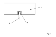
- Fig. 3 schematically the arrangement of the insulation displacement terminal 7 is shown on the cell connector 3.
- the insulation displacement terminal 7 is connected to the cell connector 3.
- the measuring line 4 is connected to the insulation displacement terminal 7.
- the insulation displacement terminal 7 can be connected to the cell connector 3 by a plurality of methods.
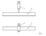
- Fig. 4 schematically shows a method in which the cutting terminal 7 is connected by so-called "shooting" with the cell connector 3.
- the insulation displacement terminal 7 is advantageously made of a harder material than the cell connector 3.
- the cell connector 3 may alternatively have corresponding holes.
- Fig. 5 a method is shown schematically in which the insulation displacement terminal 7 is pressed into the cell connector 3.
- the insulation displacement terminal 7 may have one or more extensions, which can be pressed into corresponding bores of the cell connector 3.
- Fig. 6 shown schematically.
- the insulation displacement terminal 7 is connected to the cell connector 3 by soldering.
- any suitable gluing or welding process can be used.
Landscapes
- Chemical & Material Sciences (AREA)
- Chemical Kinetics & Catalysis (AREA)
- Electrochemistry (AREA)
- General Chemical & Material Sciences (AREA)
- Inorganic Chemistry (AREA)
- Engineering & Computer Science (AREA)
- Manufacturing & Machinery (AREA)
- Connection Of Batteries Or Terminals (AREA)
- Battery Mounting, Suspending (AREA)
Abstract
Description
- Zellverbinder für ein Batteriesystem das mehrere Batteriezellen umfasst, wobei durch den Zellverbinder ein Pol einer Batteriezelle mit einem Pol einer angrenzenden Batteriezelle elektrisch leitend verbindbar ist.
- Derartige Vorrichtungen werden zum Verbinden von Polen benachbarter Batteriezellen verwendet. Die Batteriezellen sind dabei beispielsweise so angeordnet, dass ein positiver Pol und ein negativer Pol einer angrenzenden Batteriezelle einander gegenüberliegend angeordnet sind.
- Die Zellverbinder dienen in erster Linie zum elektrischen Verbinden der Batteriezellen. Durch ihre Lage eignen sie sich zum Befestigen von Zellspannungsabgriffen. An den Zellspannungsabgriffen können Mess-Leitungen befestigt werden, die in weiterer Folge zu einer Elektronikeinheit führen. Die Elektronikeinheit dient zur Überwachung der Batteriezellen und erfasst beispielsweise den Ladezustand oder auch die Temperatur der einzelnen Batteriezellen.
- Die Pole der Batteriezellen sind beispielsweise aus Aluminium bzw. einer Aluminiumlegierung hergestellt. Die Pole können aber auch aus einem anderen Werkstoff hergestellt sein, wie beispielsweise Kupfer oder Stahl. Es sind auch Mischbauformen, mit einem Pol aus Kupfer und einem Pol aus Aluminium im Stand der Technik bekannt. Mess-Leitungen werden aus Kosten- und Herstellungsgründen zumeist aus Kupfer gefertigt und sind mit einer elektrisch isolierenden Schicht überzogen.
- Aus der
DE102009033044A1 ist eine Stromzuführeinheit bekannt, welche eine Vielzahl von Sammelschienen, die jeweils ein Paar von Verbindungsteilen, die jeweils mit den angrenzenden Elektroden der angrenzenden Batterien verbunden sind, sowie einen Kopplungsteil aufweisen, der die paarigen Verbindungsteile miteinander koppelt, einen Vielzahl von Klemmelementen, mit denen die Elektroden und die Verbindungsteile festgeklemmt werden, um die Elektroden elektrisch mit den Verbindungsteilen zu verbinden, und eine Platte enthält, an der die Sammelschienen und die Klemmelemente angebracht sind. - Nachteilig bei dieser Ausführung ist der aufwendige Aufbau der Klemmenelemente, welche durch Klemmen oder Aufpressen mit den Elektroden von Batteriezellen verbunden werden, wobei die elektrischen Drähte integral mit den Klemmelementen verbunden sind.
- Es ist eine Aufgabe der Erfindung einen verbesserten Zellverbinder und ein verbessertes Batteriesystem anzugeben, die eine vereinfachte Befestigung von Mess-Leitung ermöglichen.
- Die Lösung der Aufgabe erfolgt durch einen Zellverbinder für ein Batteriesystem das mehrere Batteriezellen umfasst, wobei durch den Zellverbinder ein Pol einer Batteriezelle mit einem Pol einer angrenzenden Batteriezelle elektrisch leitend verbindbar ist, wobei der Zellverbinder aus einem ersten Werkstoff besteht, und wobei am Zellverbinder zum Abgriff der elektrischen Spannung zumindest eine Schneidklemme vorgesehen ist, wobei die Schneidklemme aus einem zweiten Werkstoff besteht oder mit einem zweiten Werkstoff zumindest teilweise beschichtet ist.
- Dadurch ist es möglich, eine relativ kleine Klemmverbindung herzustellen, wodurch Kosten und Gewicht, bei geringerem Bauraum, reduziert werden können. Es wird weiters eine bessere elektrisch leitende Verbindung zwischen den Polen der Zellen und der Messleitung ermöglicht. Ein weiterer Vorteil ist, dass die Mess-Leitungen lösbar mit den Zellverbindern verbunden sind.
- Der Vorteil bei der Verwendung von Schneidklemmen ist, dass die Adern einer Mess-Leitung, mit Hilfe eines speziellen Werkzeugs, in die Schneidklemmen gepresst werden können, ohne die Mess-Leitung zuvor Abisolieren zu müssen. Aufgrund scharfer Kontakte in der metallischen Schneidklemme wird die Isolierung der Ader durchtrennt und eine gasdichte Verbindung hergestellt. Da es sich um eine löt-, schraub- und abisolierfreie Verbindungstechnik handelt, wird diese Technik oft als LSA- Technik bezeichnet.
- Mit Hilfe dieser Technik lassen sich eine große Anzahl von Kabeln rasch und prozesssicher elektrisch und mechanisch kontaktieren, was besonders bei einem Batteriesystem mit einer hohen Anzahl an Batteriezellen zu einer großen Zeitersparnis führt.
- Um eine gute Kontaktierung der Mess-Leitung in der Schneidklemme zu gewährleisten, ist es besonders vorteilhaft, dass die Schneidklemme und die Mess-Leitung aufeinander abgestimmt sind.
- Weiterbildungen der Erfindung sind in den abhängigen Ansprüchen, der Beschreibung sowie den beigefügten Zeichnungen angegeben.
- In einer erfinderischen Ausgestaltung erfolgt die Verbindung der Schneidklemme mit dem Zellverbinder durch beispielsweise Löten oder Ultraschallschweißen. Diese Technologien sind dem Fachmann hinlänglich bekannt und werden daher nicht beschrieben.
- Alternativ kann die Schneidklemme durch Einpressen in den Zellverbinder mit diesen verbunden werden. Hierbei weist die Schneidklemme zumindest einen Fortsatz auf, welcher in zumindest eine entsprechend vorgefertigte Bohrung des Zellverbinders eingepresst wird.
- Ein weiteres Verfahren ist das sogenannte "Schießen". Es handelt sich hierbei um eine Direktmontage, welche es als ein- oder mehrstufiges Befestigungsverfahren gibt. Beim einstufigen Verfahren wird ein Fortsatz der Schneidklemme ohne weitere Vorarbeiten (z.B. Bohren) direkt in den Zellverbinder eingetrieben. Dabei ist es von Vorteil, wenn die Schneidklemme, zumindest jedoch der Fortsatz, aus einem härteren Werkstoff als der Zellverbinder ausgebildet ist. Die Schneidklemme könnte beispielsweise einen spitzen Zapfen als Fortsatz aufweisen welcher beim "Schießen" durch den Zellverbinder getrieben wird.
- Beim mehrstufigen Verfahren wird im Zellverbinder eine Bohrung mit geringer Tiefe erstellt. In diese Bohrung wird die Schneidklemme, wie beim einstufigen Verfahren, eingetrieben.
- Beim Schießen handelt es sich um eine stoffschlüssige Kaltverformungskontaktierung.
- Da beim Schießen und Einpressen die Schneidklemme zumindest einen Fortsatz aufweisen kann, welcher nach der Verbindung der Schneidklemme mit dem Zellverbinder durch diesen ragen kann, ist, bei der Verbindung des Zellverbinders mit einem Polanschluss einer Batteriezelle, darauf zu achten, dass eine ausreichend großer Abstand zwischen dem Fortsatz der Schneidklemme und der Oberfläche der Batteriezelle vorhanden ist, um eine Beschädigung der Oberfläche der Batteriezelle zu vermeiden bzw. eine ausreichend große elektrische Luft- / Kriech-Strecke zwischen den Bauteilen zu erreichen.
- Dies kann durch eine entsprechende Höhe des Polanschlusses oder eine entsprechende geometrische Ausbildung des Zellverbinders erreicht werden.
- Es kann natürlich im Rahmen der Erfindung jedes weitere dem Fachmann bekannte Verbindungsverfahren, zur geeigneten Verbindung der Schneidklemme mit dem Zellverbinder, beispielsweise Kleben, angewendet werden.
- Die Verbindungsverfahren zur Herstellung der Verbindung der Schneidklemme mit dem Zellverbinder sind für den jeweiligen Anwendungsfall so angepasst, dass eine automatisierte Fertigung möglich ist.
- Vorzugsweise besteht der Zellverbinder aus dem gleichen Material wie die Pole der Batteriezellen, beispielsweise kann dies Aluminium bzw. eine Aluminiumlegierung sein.
- In einer bevorzugten Ausführungsform ist die Schneidklemme aus Nickel gefertigt, da Nickel günstige Eigenschaften hinsichtlich elektrischer Leitfähigkeit und Korrosionsbeständigkeit aufweist.
- In einer weiteren bevorzugten Ausführungsform besteht die Schneidklemme aus Kupfer und wird zumindest teilweise mit Nickel bzw. einer Nickellegierung beschichtet. Alternativ kann die Schneidklemme aus Kupfer mit einer Zinn-Beschichtung versehen sein.
- Die Mess-Leitung ist zumeist eine Kupferleitung, da Kupfer ein guter Leiter ist. Die Herstellung einer solchen Leitung ist einfach und günstig.
- Gemäß einer Ausführungsform der Erfindung wird eine Mess-Leitung in die Schneidklemme eingeführt.
- Die Einführung der Mess-Leitung in die Schneidklemme kann hierbei vorzugsweise automatisiert erfolgen, wodurch eine schnelle, sichere und kostengünstige Montage realisiert werden kann.
- Die Mess-Leitung ist zumindest abschnittsweise mit einer Isolationsschicht überzogen, um ungewollten Kontakt mit anderen elektrisch leitenden Bauteilen zu vermeiden.
- In einer weiteren Ausführungsform ist die Mess-Leitung mit einer Elektronikeinheit mittels Schneidklemme oder Crimp verbunden. Die Schneidklemme kann hierbei auf der Mess-Leitung oder der Elektronikeinheit vorgesehen werden.
- Die Erfindung wird im Folgenden beispielhaft unter Bezugnahme auf die Zeichnungen beschrieben.
- Fig. 1
- zeigt eine Draufsicht eines Batteriesystems aus mehreren Zellen bestehend, mit erfindungsgemäßen Zellverbindern.
- Fig. 2
- zeigt eine Detailansicht gemäß
Fig. 1 von oben. - Fig. 3
- zeigt eine Anordnung einer Schneidklemme auf einem Zellverbinder.
- Fig. 4
- zeigt eine weitere Anordnung einer Schneidklemme auf einem Zellverbinder.
- Fig. 5; 6; 7
- zeigen Verbindungsverfahren zur Anbringung einer Schneidklemme auf einem Zellverbinder.
- In
Fig. 1 wird schematisch eine erfindungsgemäße Anordnung eines Batteriesystems 1 bestehend aus mehreren Batteriezellen 2, welche durch Zellverbinder 3 miteinander in Reihe geschalten sind, dargestellt. Solche Batteriesysteme sind beispielsweise in Elektrofahrzeugen und Hybridfahrzeugen in Verwendung. Zum Spannungsabgriff der Batteriezellen 2 werden Mess-Leitungen 4 eingesetzt, welche an einem Ende mit einer Elektronikeinheit 5 und am anderen Ende mit einer Schneidklemme 7 verbunden sind. Die Elektronikeinheit 5 wandelt die von der Messleitung 4 übertragenen elektrischen Spannungen in digitale Signale um. Diese Signale werden in weiterer Folge zur Steuerung des Batteriesystems herangezogen. Die Schneidklemme 7 ist an einem Zellverbinder 3 angeordnet. Der Zellverbinder 3 ist mit einem positiven Pol 6 einer Batteriezelle 2 und einem negativen Pol 6 einer weiteren, benachbarten, Batteriezelle 2 elektrisch verbunden. -
Fig. 2 zeigt eine Detailansicht vonFig. 1 , wobei auf dem Zellverbinder 3 die Schneidklemme 7 schematisch dargestellt ist. Die Mess-Leitung 4 ist mit der Schneidklemme 7 elektrisch leitfähig verbunden. Der Zellverbinder 3 ist mit einem positiven Pol 6 einer Batteriezelle 2 und einem negativen Pol 6 einer angrenzenden Batteriezelle 2 elektrisch leitfähig verbunden, beispielsweise durch eine stoffschlüssige Verbindung. Die Messleitung 4 überträgt die elektrische Spannung die am Zellverbinder 3 anliegt an die Elektronikeinheit 5 (nicht dargestellt). - In
Fig. 3 wird schematisch die Anordnung der Schneidklemme 7 am Zellverbinder 3 dargestellt. Die Schneidklemme 7 ist mit dem Zellverbinder 3 verbunden. Die Mess-Leitung 4 ist mit der Schneidklemme 7 verbunden. Die Schneidklemme 7 kann mittels mehrerer Verfahren mit dem Zellverbinder 3 verbunden werden.Fig. 4 zeigt schematisch ein Verfahren, bei dem die Schneidklemme 7 durch sogenanntes "Schießen" mit dem Zellverbinder 3 verbunden wird. Bei diesem Verfahren ist die Schneidklemme 7 vorteilhaft aus einem härteren Werkstoff als der Zellverbinder 3 ausgeführt. Der Zellverbinder 3 kann alternativ entsprechende Bohrungen aufweisen. InFig. 5 wird ein Verfahren schematisch dargestellt, bei dem die Schneidklemme 7 in den Zellverbinder 3 eingepresst wird. Die Schneidklemme 7 kann einen oder mehrere Fortsätze aufweisen, welche in entsprechende Bohrungen des Zellverbinders 3 einpressbar sind. Ein weiteres Verfahren wird inFig. 6 schematisch dargestellt. Bei diesem Verfahren wird die Schneidklemme 7 durch Löten mit dem Zellverbinder 3 verbunden. Es kann natürlich auch jedes geeignetes Klebe- oder Schweißverfahren angewendet werden. -
- 1
- Batteriesystem
- 2
- Batteriezelle
- 3
- Zellverbinder
- 4
- Mess-Leitung
- 5
- Elektronikeinheit
- 6
- Pol
- 7
- Schneidklemme
Claims (10)
- Zellverbinder (3) für ein Batteriesystem (1) das mehrere Batteriezellen (2) umfasst, wobei durch den Zellverbinder (3) ein Pol (6) einer Batteriezelle (2) mit einem Pol (6) einer angrenzenden Batteriezelle (2) elektrisch leitend verbindbar ist,
dadurch gekennzeichnet, dass der Zellverbinder (3) aus einem ersten Werkstoff besteht, und wobei am Zellverbinder (3) zum Abgriff der elektrischen Spannung zumindest eine Schneidklemme (7) vorgesehen ist, wobei die Schneidklemme (7) aus einem zweiten Werkstoff besteht oder mit einem zweiten Werkstoff zumindest teilweise beschichtet ist. - Zellverbinder (3) nach Anspruch 1,
dadurch gekennzeichnet, dass die Schneidklemme (7) auf den Zellverbinder (3) gelötet oder mit dem Zellverbinder (3) ultraschallgeschweißt oder in den Zellverbinder (3) eingepresst oder eingeschossen ist. - Zellverbinder (3) nach Anspruch 1,
dadurch gekennzeichnet, dass der Zellverbinder (3) aus Aluminium bzw. aus einer Aluminiumlegierung besteht. - Zellverbinder (3) nach Anspruch 1,
dadurch gekennzeichnet, dass die Schneidklemme (7) aus Nickel besteht. - Zellverbinder (3) nach Anspruch 1,
dadurch gekennzeichnet, dass die Schneidklemme (7) aus Kupfer besteht. - Zellverbinder (3) nach Anspruch 5,
dadurch gekennzeichnet, dass die Schneidklemme (7) zumindest teilweise verzinnt ist. - Zellverbinder (3) nach Anspruch 5,
dadurch gekennzeichnet, dass die Schneidklemme (7) zumindest teilweise vernickelt ist. - Batteriesystem (1) mit mehreren Batteriezellen (2) mit Zellverbindern (3) nach Anspruch 1,
dadurch gekennzeichnet, dass in die Schneidklemme (7) eine Mess-Leitung (4) einführbar ist. - Batteriesystem (1) mit mehreren Batteriezellen (2) mit Zellverbindern (3) nach Anspruch 5,
dadurch gekennzeichnet, dass die Mess-Leitung (4) aus Kupfer besteht und mit einer elektrischen Isolationsschicht überzogen ist. - Batteriesystem (1) mit mehreren Batteriezellen (2) mit Zellverbindern (3) nach Anspruch 5,
dadurch gekennzeichnet, dass die Mess-Leitung (4) mit einer Elektronikeinheit (5) mittels einer weiteren Schneidklemme verbindbar ist.
Priority Applications (1)
| Application Number | Priority Date | Filing Date | Title |
|---|---|---|---|
| EP12188364.9A EP2720298B1 (de) | 2012-10-12 | 2012-10-12 | Zellverbinder für ein Batteriesystem |
Applications Claiming Priority (1)
| Application Number | Priority Date | Filing Date | Title |
|---|---|---|---|
| EP12188364.9A EP2720298B1 (de) | 2012-10-12 | 2012-10-12 | Zellverbinder für ein Batteriesystem |
Publications (2)
| Publication Number | Publication Date |
|---|---|
| EP2720298A1 true EP2720298A1 (de) | 2014-04-16 |
| EP2720298B1 EP2720298B1 (de) | 2016-12-07 |
Family
ID=47040576
Family Applications (1)
| Application Number | Title | Priority Date | Filing Date |
|---|---|---|---|
| EP12188364.9A Active EP2720298B1 (de) | 2012-10-12 | 2012-10-12 | Zellverbinder für ein Batteriesystem |
Country Status (1)
| Country | Link |
|---|---|
| EP (1) | EP2720298B1 (de) |
Cited By (1)
| Publication number | Priority date | Publication date | Assignee | Title |
|---|---|---|---|---|
| DE102015014241A1 (de) | 2015-11-05 | 2017-05-11 | Daimler Ag | Zellverbinder und Verfahren zur Herstellung einer elektrischen Batterie |
Citations (6)
| Publication number | Priority date | Publication date | Assignee | Title |
|---|---|---|---|---|
| US5788539A (en) * | 1996-05-30 | 1998-08-04 | The Whitaker Corporation | Surface mountable electrical connector |
| DE102009033044A1 (de) | 2008-08-27 | 2010-03-04 | Yazaki Corp. | Stromzuführeinheit |
| US20110045329A1 (en) * | 2009-08-18 | 2011-02-24 | Yazaki Corporation | Power-supply device |
| JP2011049047A (ja) * | 2009-08-27 | 2011-03-10 | Autonetworks Technologies Ltd | 電池接続アセンブリ |
| US20110117769A1 (en) * | 2008-07-25 | 2011-05-19 | Sumitomo Wiring Systems, Ltd. | Insulation displacement terminal, splicing terminal assembly and press-contact structure for electric cable |
| US20120015550A1 (en) * | 2009-08-18 | 2012-01-19 | Yazaki Corporation | Power unit and battery connector |
-
2012
- 2012-10-12 EP EP12188364.9A patent/EP2720298B1/de active Active
Patent Citations (6)
| Publication number | Priority date | Publication date | Assignee | Title |
|---|---|---|---|---|
| US5788539A (en) * | 1996-05-30 | 1998-08-04 | The Whitaker Corporation | Surface mountable electrical connector |
| US20110117769A1 (en) * | 2008-07-25 | 2011-05-19 | Sumitomo Wiring Systems, Ltd. | Insulation displacement terminal, splicing terminal assembly and press-contact structure for electric cable |
| DE102009033044A1 (de) | 2008-08-27 | 2010-03-04 | Yazaki Corp. | Stromzuführeinheit |
| US20110045329A1 (en) * | 2009-08-18 | 2011-02-24 | Yazaki Corporation | Power-supply device |
| US20120015550A1 (en) * | 2009-08-18 | 2012-01-19 | Yazaki Corporation | Power unit and battery connector |
| JP2011049047A (ja) * | 2009-08-27 | 2011-03-10 | Autonetworks Technologies Ltd | 電池接続アセンブリ |
Cited By (1)
| Publication number | Priority date | Publication date | Assignee | Title |
|---|---|---|---|---|
| DE102015014241A1 (de) | 2015-11-05 | 2017-05-11 | Daimler Ag | Zellverbinder und Verfahren zur Herstellung einer elektrischen Batterie |
Also Published As
| Publication number | Publication date |
|---|---|
| EP2720298B1 (de) | 2016-12-07 |
Similar Documents
| Publication | Publication Date | Title |
|---|---|---|
| DE102009050315B4 (de) | Verbindungsvorrichtung, elektrochemische Vorrichtung und Verfahren zum elektrisch leitenden Verbinden von Zellterminals von elektrochemischen Zellen einer elektrochemischen Vorrichtung | |
| EP3031103B1 (de) | System aus mehreren elektrischen steckverbindermodulen und einem elektrisch leitfähigen halterahmen | |
| DE102014004432A1 (de) | Elektrische Leitungsvorrichtung, insbesondere für ein Kraftfahrzeug | |
| EP4503344B1 (de) | Konfektioniertes elektrisches kabel und steckverbinderanordnung | |
| WO2015197319A1 (de) | Übertragungsvorrichtung zum übertragen von elektrischen signalen von wenigstens einer galvanischen zelle an zumindest eine elektronische auswerteeinheit | |
| EP3080871B1 (de) | Kontaktierungselement | |
| EP2949004B1 (de) | Verfahren zum herstellen einer elektrisch leitenden verbindung zwischen einer elektrischen leitung und einem elektrisch leitenden bauteil und nach dem verfahren hergestellte baugruppe | |
| EP3698438B1 (de) | Vorrichtung zur elektrischen kontaktierung | |
| DE202007013957U1 (de) | Leiter mit Kontaktteil | |
| EP2658034A1 (de) | Spannungsabgriffelement, Zellüberwachungseinheit, Batterieeinheit und Herstellungsverfahren dazu | |
| EP1841010A2 (de) | Elektrischer Kontaktstift | |
| DE102015110308B4 (de) | Akkupack für ein Elektrohandwerkzeuggerät | |
| EP2800168B1 (de) | Batteriesystem und Verfahren zur Herstellung einer elektrisch leitenden Verbindung zwischen einem Zellverbinder und einer Elektronikeinheit eines Batteriesystems | |
| EP2609653B1 (de) | Vorrichtung umfassend ein Gehäuse mit einem Schaltungsträger | |
| EP2720320B1 (de) | Zellverbinder für ein Batteriesystem | |
| EP3206258B1 (de) | System zur herstellung einer elektrischen verbindung, elektrische verbindung und verfahren zu deren herstellung | |
| EP2711726B1 (de) | Vorrichtung zur Spannungsüberwachung | |
| DE102013201556B4 (de) | Batteriesystem mit einem Kontaktelement | |
| EP2720298B1 (de) | Zellverbinder für ein Batteriesystem | |
| WO2012142999A2 (de) | Hochstromkontaktelement für leiterplatten | |
| EP2524407B1 (de) | Batterie, batteriesystem und verfahren zur verbindung einer mehrzahl von batterien | |
| EP2793288B1 (de) | Batteriesystem und Verfahren zur Herstellung einer elektrisch leitenden Verbindung zwischen einem Zellverbinder und einer Elektronikeinheit eines Batteriesystems | |
| EP2820696B1 (de) | Batterie mit wenigstens zwei batteriezellen und mit wenigstens einem verbindungselement | |
| EP2706620B1 (de) | Verfahren zum Abdichten eines elektrischen Kupplungsteils und damit hergestelltes Kupplungsteil | |
| EP2747205B1 (de) | Verfahren zum elektrisch leitenden Verbinden eines Litzenleiters mit einem Kontaktelement |
Legal Events
| Date | Code | Title | Description |
|---|---|---|---|
| PUAI | Public reference made under article 153(3) epc to a published international application that has entered the european phase |
Free format text: ORIGINAL CODE: 0009012 |
|
| AK | Designated contracting states |
Kind code of ref document: A1 Designated state(s): AL AT BE BG CH CY CZ DE DK EE ES FI FR GB GR HR HU IE IS IT LI LT LU LV MC MK MT NL NO PL PT RO RS SE SI SK SM TR |
|
| AX | Request for extension of the european patent |
Extension state: BA ME |
|
| 17P | Request for examination filed |
Effective date: 20140926 |
|
| RBV | Designated contracting states (corrected) |
Designated state(s): AL AT BE BG CH CY CZ DE DK EE ES FI FR GB GR HR HU IE IS IT LI LT LU LV MC MK MT NL NO PL PT RO RS SE SI SK SM TR |
|
| RAP1 | Party data changed (applicant data changed or rights of an application transferred) |
Owner name: MAGNA STEYR BATTERY SYSTEMS GMBH & CO OG |
|
| RAP1 | Party data changed (applicant data changed or rights of an application transferred) |
Owner name: SAMSUNG SDI CO., LTD. |
|
| 17Q | First examination report despatched |
Effective date: 20160401 |
|
| GRAP | Despatch of communication of intention to grant a patent |
Free format text: ORIGINAL CODE: EPIDOSNIGR1 |
|
| RIC1 | Information provided on ipc code assigned before grant |
Ipc: H01M 2/20 20060101AFI20160616BHEP Ipc: H01M 10/48 20060101ALI20160616BHEP Ipc: H01R 31/08 20060101ALI20160616BHEP Ipc: G01R 31/36 20060101ALN20160616BHEP |
|
| INTG | Intention to grant announced |
Effective date: 20160704 |
|
| GRAS | Grant fee paid |
Free format text: ORIGINAL CODE: EPIDOSNIGR3 |
|
| GRAA | (expected) grant |
Free format text: ORIGINAL CODE: 0009210 |
|
| STAA | Information on the status of an ep patent application or granted ep patent |
Free format text: STATUS: THE PATENT HAS BEEN GRANTED |
|
| AK | Designated contracting states |
Kind code of ref document: B1 Designated state(s): AL AT BE BG CH CY CZ DE DK EE ES FI FR GB GR HR HU IE IS IT LI LT LU LV MC MK MT NL NO PL PT RO RS SE SI SK SM TR |
|
| REG | Reference to a national code |
Ref country code: GB Ref legal event code: FG4D Free format text: NOT ENGLISH |
|
| REG | Reference to a national code |
Ref country code: CH Ref legal event code: EP Ref country code: AT Ref legal event code: REF Ref document number: 852425 Country of ref document: AT Kind code of ref document: T Effective date: 20161215 |
|
| REG | Reference to a national code |
Ref country code: IE Ref legal event code: FG4D Free format text: LANGUAGE OF EP DOCUMENT: GERMAN |
|
| REG | Reference to a national code |
Ref country code: DE Ref legal event code: R096 Ref document number: 502012008961 Country of ref document: DE |
|
| PG25 | Lapsed in a contracting state [announced via postgrant information from national office to epo] |
Ref country code: LV Free format text: LAPSE BECAUSE OF FAILURE TO SUBMIT A TRANSLATION OF THE DESCRIPTION OR TO PAY THE FEE WITHIN THE PRESCRIBED TIME-LIMIT Effective date: 20161207 |
|
| REG | Reference to a national code |
Ref country code: LT Ref legal event code: MG4D |
|
| REG | Reference to a national code |
Ref country code: NL Ref legal event code: MP Effective date: 20161207 |
|
| PG25 | Lapsed in a contracting state [announced via postgrant information from national office to epo] |
Ref country code: NO Free format text: LAPSE BECAUSE OF FAILURE TO SUBMIT A TRANSLATION OF THE DESCRIPTION OR TO PAY THE FEE WITHIN THE PRESCRIBED TIME-LIMIT Effective date: 20170307 Ref country code: SE Free format text: LAPSE BECAUSE OF FAILURE TO SUBMIT A TRANSLATION OF THE DESCRIPTION OR TO PAY THE FEE WITHIN THE PRESCRIBED TIME-LIMIT Effective date: 20161207 Ref country code: GR Free format text: LAPSE BECAUSE OF FAILURE TO SUBMIT A TRANSLATION OF THE DESCRIPTION OR TO PAY THE FEE WITHIN THE PRESCRIBED TIME-LIMIT Effective date: 20170308 Ref country code: LT Free format text: LAPSE BECAUSE OF FAILURE TO SUBMIT A TRANSLATION OF THE DESCRIPTION OR TO PAY THE FEE WITHIN THE PRESCRIBED TIME-LIMIT Effective date: 20161207 |
|
| PG25 | Lapsed in a contracting state [announced via postgrant information from national office to epo] |
Ref country code: HR Free format text: LAPSE BECAUSE OF FAILURE TO SUBMIT A TRANSLATION OF THE DESCRIPTION OR TO PAY THE FEE WITHIN THE PRESCRIBED TIME-LIMIT Effective date: 20161207 Ref country code: ES Free format text: LAPSE BECAUSE OF FAILURE TO SUBMIT A TRANSLATION OF THE DESCRIPTION OR TO PAY THE FEE WITHIN THE PRESCRIBED TIME-LIMIT Effective date: 20161207 Ref country code: FI Free format text: LAPSE BECAUSE OF FAILURE TO SUBMIT A TRANSLATION OF THE DESCRIPTION OR TO PAY THE FEE WITHIN THE PRESCRIBED TIME-LIMIT Effective date: 20161207 Ref country code: RS Free format text: LAPSE BECAUSE OF FAILURE TO SUBMIT A TRANSLATION OF THE DESCRIPTION OR TO PAY THE FEE WITHIN THE PRESCRIBED TIME-LIMIT Effective date: 20161207 |
|
| PG25 | Lapsed in a contracting state [announced via postgrant information from national office to epo] |
Ref country code: NL Free format text: LAPSE BECAUSE OF FAILURE TO SUBMIT A TRANSLATION OF THE DESCRIPTION OR TO PAY THE FEE WITHIN THE PRESCRIBED TIME-LIMIT Effective date: 20161207 |
|
| PG25 | Lapsed in a contracting state [announced via postgrant information from national office to epo] |
Ref country code: EE Free format text: LAPSE BECAUSE OF FAILURE TO SUBMIT A TRANSLATION OF THE DESCRIPTION OR TO PAY THE FEE WITHIN THE PRESCRIBED TIME-LIMIT Effective date: 20161207 Ref country code: SK Free format text: LAPSE BECAUSE OF FAILURE TO SUBMIT A TRANSLATION OF THE DESCRIPTION OR TO PAY THE FEE WITHIN THE PRESCRIBED TIME-LIMIT Effective date: 20161207 Ref country code: IS Free format text: LAPSE BECAUSE OF FAILURE TO SUBMIT A TRANSLATION OF THE DESCRIPTION OR TO PAY THE FEE WITHIN THE PRESCRIBED TIME-LIMIT Effective date: 20170407 Ref country code: CZ Free format text: LAPSE BECAUSE OF FAILURE TO SUBMIT A TRANSLATION OF THE DESCRIPTION OR TO PAY THE FEE WITHIN THE PRESCRIBED TIME-LIMIT Effective date: 20161207 Ref country code: RO Free format text: LAPSE BECAUSE OF FAILURE TO SUBMIT A TRANSLATION OF THE DESCRIPTION OR TO PAY THE FEE WITHIN THE PRESCRIBED TIME-LIMIT Effective date: 20161207 |
|
| PG25 | Lapsed in a contracting state [announced via postgrant information from national office to epo] |
Ref country code: IT Free format text: LAPSE BECAUSE OF FAILURE TO SUBMIT A TRANSLATION OF THE DESCRIPTION OR TO PAY THE FEE WITHIN THE PRESCRIBED TIME-LIMIT Effective date: 20161207 Ref country code: PT Free format text: LAPSE BECAUSE OF FAILURE TO SUBMIT A TRANSLATION OF THE DESCRIPTION OR TO PAY THE FEE WITHIN THE PRESCRIBED TIME-LIMIT Effective date: 20170407 Ref country code: BG Free format text: LAPSE BECAUSE OF FAILURE TO SUBMIT A TRANSLATION OF THE DESCRIPTION OR TO PAY THE FEE WITHIN THE PRESCRIBED TIME-LIMIT Effective date: 20170307 Ref country code: SM Free format text: LAPSE BECAUSE OF FAILURE TO SUBMIT A TRANSLATION OF THE DESCRIPTION OR TO PAY THE FEE WITHIN THE PRESCRIBED TIME-LIMIT Effective date: 20161207 Ref country code: PL Free format text: LAPSE BECAUSE OF FAILURE TO SUBMIT A TRANSLATION OF THE DESCRIPTION OR TO PAY THE FEE WITHIN THE PRESCRIBED TIME-LIMIT Effective date: 20161207 |
|
| REG | Reference to a national code |
Ref country code: DE Ref legal event code: R097 Ref document number: 502012008961 Country of ref document: DE |
|
| REG | Reference to a national code |
Ref country code: FR Ref legal event code: PLFP Year of fee payment: 6 |
|
| PLBE | No opposition filed within time limit |
Free format text: ORIGINAL CODE: 0009261 |
|
| STAA | Information on the status of an ep patent application or granted ep patent |
Free format text: STATUS: NO OPPOSITION FILED WITHIN TIME LIMIT |
|
| 26N | No opposition filed |
Effective date: 20170908 |
|
| PG25 | Lapsed in a contracting state [announced via postgrant information from national office to epo] |
Ref country code: DK Free format text: LAPSE BECAUSE OF FAILURE TO SUBMIT A TRANSLATION OF THE DESCRIPTION OR TO PAY THE FEE WITHIN THE PRESCRIBED TIME-LIMIT Effective date: 20161207 Ref country code: SI Free format text: LAPSE BECAUSE OF FAILURE TO SUBMIT A TRANSLATION OF THE DESCRIPTION OR TO PAY THE FEE WITHIN THE PRESCRIBED TIME-LIMIT Effective date: 20161207 |
|
| PG25 | Lapsed in a contracting state [announced via postgrant information from national office to epo] |
Ref country code: MC Free format text: LAPSE BECAUSE OF FAILURE TO SUBMIT A TRANSLATION OF THE DESCRIPTION OR TO PAY THE FEE WITHIN THE PRESCRIBED TIME-LIMIT Effective date: 20161207 |
|
| REG | Reference to a national code |
Ref country code: CH Ref legal event code: PL |
|
| REG | Reference to a national code |
Ref country code: IE Ref legal event code: MM4A |
|
| PG25 | Lapsed in a contracting state [announced via postgrant information from national office to epo] |
Ref country code: LI Free format text: LAPSE BECAUSE OF NON-PAYMENT OF DUE FEES Effective date: 20171031 Ref country code: CH Free format text: LAPSE BECAUSE OF NON-PAYMENT OF DUE FEES Effective date: 20171031 Ref country code: LU Free format text: LAPSE BECAUSE OF NON-PAYMENT OF DUE FEES Effective date: 20171012 |
|
| REG | Reference to a national code |
Ref country code: BE Ref legal event code: MM Effective date: 20171031 |
|
| PG25 | Lapsed in a contracting state [announced via postgrant information from national office to epo] |
Ref country code: BE Free format text: LAPSE BECAUSE OF NON-PAYMENT OF DUE FEES Effective date: 20171031 |
|
| PG25 | Lapsed in a contracting state [announced via postgrant information from national office to epo] |
Ref country code: MT Free format text: LAPSE BECAUSE OF FAILURE TO SUBMIT A TRANSLATION OF THE DESCRIPTION OR TO PAY THE FEE WITHIN THE PRESCRIBED TIME-LIMIT Effective date: 20161207 |
|
| REG | Reference to a national code |
Ref country code: FR Ref legal event code: PLFP Year of fee payment: 7 |
|
| PG25 | Lapsed in a contracting state [announced via postgrant information from national office to epo] |
Ref country code: IE Free format text: LAPSE BECAUSE OF NON-PAYMENT OF DUE FEES Effective date: 20171012 |
|
| REG | Reference to a national code |
Ref country code: AT Ref legal event code: MM01 Ref document number: 852425 Country of ref document: AT Kind code of ref document: T Effective date: 20171012 |
|
| PG25 | Lapsed in a contracting state [announced via postgrant information from national office to epo] |
Ref country code: AT Free format text: LAPSE BECAUSE OF NON-PAYMENT OF DUE FEES Effective date: 20171012 |
|
| PG25 | Lapsed in a contracting state [announced via postgrant information from national office to epo] |
Ref country code: HU Free format text: LAPSE BECAUSE OF FAILURE TO SUBMIT A TRANSLATION OF THE DESCRIPTION OR TO PAY THE FEE WITHIN THE PRESCRIBED TIME-LIMIT; INVALID AB INITIO Effective date: 20121012 |
|
| PG25 | Lapsed in a contracting state [announced via postgrant information from national office to epo] |
Ref country code: CY Free format text: LAPSE BECAUSE OF NON-PAYMENT OF DUE FEES Effective date: 20161207 |
|
| PG25 | Lapsed in a contracting state [announced via postgrant information from national office to epo] |
Ref country code: MK Free format text: LAPSE BECAUSE OF FAILURE TO SUBMIT A TRANSLATION OF THE DESCRIPTION OR TO PAY THE FEE WITHIN THE PRESCRIBED TIME-LIMIT Effective date: 20161207 |
|
| PG25 | Lapsed in a contracting state [announced via postgrant information from national office to epo] |
Ref country code: TR Free format text: LAPSE BECAUSE OF FAILURE TO SUBMIT A TRANSLATION OF THE DESCRIPTION OR TO PAY THE FEE WITHIN THE PRESCRIBED TIME-LIMIT Effective date: 20161207 |
|
| PG25 | Lapsed in a contracting state [announced via postgrant information from national office to epo] |
Ref country code: AL Free format text: LAPSE BECAUSE OF FAILURE TO SUBMIT A TRANSLATION OF THE DESCRIPTION OR TO PAY THE FEE WITHIN THE PRESCRIBED TIME-LIMIT Effective date: 20161207 |
|
| REG | Reference to a national code |
Ref country code: DE Ref legal event code: R079 Ref document number: 502012008961 Country of ref document: DE Free format text: PREVIOUS MAIN CLASS: H01M0002200000 Ipc: H01M0050500000 |
|
| P01 | Opt-out of the competence of the unified patent court (upc) registered |
Effective date: 20230528 |
|
| PGFP | Annual fee paid to national office [announced via postgrant information from national office to epo] |
Ref country code: FR Payment date: 20250930 Year of fee payment: 14 |
|
| PGFP | Annual fee paid to national office [announced via postgrant information from national office to epo] |
Ref country code: DE Payment date: 20250930 Year of fee payment: 14 |
|
| PGFP | Annual fee paid to national office [announced via postgrant information from national office to epo] |
Ref country code: GB Payment date: 20251001 Year of fee payment: 14 |