EP2720068A1 - Coupling device for seismic sensors - Google Patents
Coupling device for seismic sensors Download PDFInfo
- Publication number
- EP2720068A1 EP2720068A1 EP12306235.8A EP12306235A EP2720068A1 EP 2720068 A1 EP2720068 A1 EP 2720068A1 EP 12306235 A EP12306235 A EP 12306235A EP 2720068 A1 EP2720068 A1 EP 2720068A1
- Authority
- EP
- European Patent Office
- Prior art keywords
- coupling device
- supporting portion
- sensor
- housing
- sensor unit
- Prior art date
- Legal status (The legal status is an assumption and is not a legal conclusion. Google has not performed a legal analysis and makes no representation as to the accuracy of the status listed.)
- Withdrawn
Links
Images


Classifications
-
- G—PHYSICS
- G01—MEASURING; TESTING
- G01V—GEOPHYSICS; GRAVITATIONAL MEASUREMENTS; DETECTING MASSES OR OBJECTS; TAGS
- G01V1/00—Seismology; Seismic or acoustic prospecting or detecting
- G01V1/16—Receiving elements for seismic signals; Arrangements or adaptations of receiving elements
-
- G—PHYSICS
- G01—MEASURING; TESTING
- G01S—RADIO DIRECTION-FINDING; RADIO NAVIGATION; DETERMINING DISTANCE OR VELOCITY BY USE OF RADIO WAVES; LOCATING OR PRESENCE-DETECTING BY USE OF THE REFLECTION OR RERADIATION OF RADIO WAVES; ANALOGOUS ARRANGEMENTS USING OTHER WAVES
- G01S7/00—Details of systems according to groups G01S13/00, G01S15/00, G01S17/00
- G01S7/52—Details of systems according to groups G01S13/00, G01S15/00, G01S17/00 of systems according to group G01S15/00
- G01S7/521—Constructional features
-
- F—MECHANICAL ENGINEERING; LIGHTING; HEATING; WEAPONS; BLASTING
- F16—ENGINEERING ELEMENTS AND UNITS; GENERAL MEASURES FOR PRODUCING AND MAINTAINING EFFECTIVE FUNCTIONING OF MACHINES OR INSTALLATIONS; THERMAL INSULATION IN GENERAL
- F16B—DEVICES FOR FASTENING OR SECURING CONSTRUCTIONAL ELEMENTS OR MACHINE PARTS TOGETHER, e.g. NAILS, BOLTS, CIRCLIPS, CLAMPS, CLIPS OR WEDGES; JOINTS OR JOINTING
- F16B17/00—Connecting constructional elements or machine parts by a part of or on one member entering a hole in the other and involving plastic deformation
-
- F—MECHANICAL ENGINEERING; LIGHTING; HEATING; WEAPONS; BLASTING
- F16—ENGINEERING ELEMENTS AND UNITS; GENERAL MEASURES FOR PRODUCING AND MAINTAINING EFFECTIVE FUNCTIONING OF MACHINES OR INSTALLATIONS; THERMAL INSULATION IN GENERAL
- F16B—DEVICES FOR FASTENING OR SECURING CONSTRUCTIONAL ELEMENTS OR MACHINE PARTS TOGETHER, e.g. NAILS, BOLTS, CIRCLIPS, CLAMPS, CLIPS OR WEDGES; JOINTS OR JOINTING
- F16B2200/00—Constructional details of connections not covered for in other groups of this subclass
- F16B2200/60—Coupler sealing means
-
- G—PHYSICS
- G01—MEASURING; TESTING
- G01D—MEASURING NOT SPECIALLY ADAPTED FOR A SPECIFIC VARIABLE; ARRANGEMENTS FOR MEASURING TWO OR MORE VARIABLES NOT COVERED IN A SINGLE OTHER SUBCLASS; TARIFF METERING APPARATUS; MEASURING OR TESTING NOT OTHERWISE PROVIDED FOR
- G01D11/00—Component parts of measuring arrangements not specially adapted for a specific variable
- G01D11/30—Supports specially adapted for an instrument; Supports specially adapted for a set of instruments
-
- G—PHYSICS
- G01—MEASURING; TESTING
- G01V—GEOPHYSICS; GRAVITATIONAL MEASUREMENTS; DETECTING MASSES OR OBJECTS; TAGS
- G01V1/00—Seismology; Seismic or acoustic prospecting or detecting
- G01V1/16—Receiving elements for seismic signals; Arrangements or adaptations of receiving elements
- G01V1/162—Details
- G01V1/166—Arrangements for coupling receivers to the ground
-
- G—PHYSICS
- G01—MEASURING; TESTING
- G01V—GEOPHYSICS; GRAVITATIONAL MEASUREMENTS; DETECTING MASSES OR OBJECTS; TAGS
- G01V1/00—Seismology; Seismic or acoustic prospecting or detecting
- G01V1/16—Receiving elements for seismic signals; Arrangements or adaptations of receiving elements
- G01V1/18—Receiving elements, e.g. seismometer, geophone or torque detectors, for localised single point measurements
- G01V1/181—Geophones
-
- Y—GENERAL TAGGING OF NEW TECHNOLOGICAL DEVELOPMENTS; GENERAL TAGGING OF CROSS-SECTIONAL TECHNOLOGIES SPANNING OVER SEVERAL SECTIONS OF THE IPC; TECHNICAL SUBJECTS COVERED BY FORMER USPC CROSS-REFERENCE ART COLLECTIONS [XRACs] AND DIGESTS
- Y10—TECHNICAL SUBJECTS COVERED BY FORMER USPC
- Y10T—TECHNICAL SUBJECTS COVERED BY FORMER US CLASSIFICATION
- Y10T403/00—Joints and connections
- Y10T403/70—Interfitted members
Definitions
- the invention pertains to the geophysical domain, and relates to applications in which sensor units are used to map subterranean properties of a given geographical area.
- the invention relates to coupling devices for such sensor units enabling to position the sensor units on the surface of said geographical area.
- the invention may be used in various applications involving acquisition of seismic data through a network of sensor units, it is of particular interest to the oil prospection industry.
- seismic data are collected by networks of electronic sensor units, which are connected to a central processing server.
- Each sensor unit comprises at least one sensor located within a housing, which features a bottom surface intended to be mechanically coupled with the ground.
- a sensor unit is usually equipped with a coupling device having the shape of a spike, which is to be buried into the ground. Such a spike is described in a French patent application FR 2918462 .
- a spike-shaped coupling device may be insufficiently effective to ensure sensor stability in loose soil, e.g. when the ground is made of sand or mud, in which case the spike won't be maintained in position as well as it would be in a more dense, and thus less shifting, environment.
- Some known sensor units are equipped with a housing featuring a cylindrical pod protruding from the housing's bottom, the spike then being fastened to the end of said pod.
- the actual sensor is located in the pod, and thus will be located underground after the spike is properly buried into the ground. In such a configuration, the sensor will be less sensitive to surface noise.
- this design presents a drawback due to the elongated shape of the pod protruding from the housing's bottom, which will tend to resonate at a frequency comprised within the bandwidth under study and may thus significantly alter the operational performance of the sensor unit.
- the invention offers a solution which is essentially unaffected by the above mentioned drawbacks, by providing a coupling device for a sensor unit which enables said unit to stay in a stable position even if it is only laid down on the ground, and which significantly reduces the risk for a bottom pod of the sensor housing to resonate in operating conditions.
- the invention introduces a coupling device for a sensor unit comprising at least one sensor located within a housing, which coupling device includes at least one supporting portion and at least one rod, arranged in a plane which is essentially perpendicular to a peripheral surface of the supporting portion and linked to said supporting portion, said coupling device further including fastening means for connecting the sensor unit to the coupling device.
- the coupling device according to the invention is remarkable in that it enables to solve two problems simultaneously.
- the supporting portion will maintain the sensor unit in a stable position when resting on or buried into the ground, while the rod or rods linked to the supporting portion will provide an additional stiffness to the sensor unit's housing, and thus suppress resonating frequencies which would be generated by a housing.
- a coupling device as described hereinbefore will advantageously have a symmetric shape with respect to at least one plane which is essentially perpendicular with respect to the supporting portion.
- Such a symmetric shape allows a homogeneous mass distribution in the horizontal plane when the coupling device is placed on or buried into the ground, which will thus contribute to prevent the coupling device from vibrating in operating conditions.
- a coupling device as described above includes at least one rod, and features at least a first supporting portion against which said housing is to be maintained in position and a second supporting portion having a peripheral section essentially parallel to a peripheral section of the first supporting portion, said first and second supporting portions being linked together by said at least one rod.
- Such a coupling device is particularly well suited to housings featuring at least one shoulder portion against which may be positioned against the first supporting portion.
- a coupling device as described hereinbefore includes at least two rods linking together said first and second supporting portions, and at least one partially peripheral fin arranged in parallel with at least one peripheral section of the first and second supporting portions.
- a coupling device as described hereinbefore features a third supporting portion upon which an end of the housing is to be fastened, said third supporting portion being placed between the first and second supporting portions,
- the first supporting portion is provided with a groove supporting an O-ring and intended to be located between the coupling device and the housing.
- the O-ring will compensate any clearance between the third supporting portion and the end of the housing, thus ensuring that the housing and the coupling device are firmly fastened to each other. Since the third supporting portion is arranged between the first and second supporting portions, the end of the housing is located well within the coupling device when the housing is fastened to it, which will help to protect the sensor's integrity in case of an impact between the second supporting portion and the ground.
- the third supporting portion includes a through hole intended to be passed through by screwing means for fastening the end of the housing to the third supporting portion.
- the screwing means may be formed by providing the end of the housing with a male thread protruding through said hole, which male thread will then be complemented by a nut pressing against the bottom side of the third portion.
- the screwing means may be formed by providing the end of the housing with a female thread, which will then be completed by a screw whose head will press against the bottom side of the third portion.
- a bottom part of the second supporting portion includes dampening means.
- dampening means are intended to preserve the physical integrity of the sensor in cases where the assembly formed by the sensor unit and its associated coupling device is dropped on the ground.
- the peripheral sections of the supporting portions have a circular shape.
- the invention also relates to a sensor unit adapted to be fastened to a coupling device as described hereinbefore.
- said at least one sensor is a one vertical component digital sensor or a three orthogonal component digital sensor like a geophone or an accelerometer.
- said at least one sensor is digital seismic sensor.
- the coupling device according to the invention is remarkable in that it enables to solve two problems simultaneously, by means of at least one supporting portion which will maintain the sensor unit in a stable position when resting on or buried into the ground, while a rod or rods linking both supporting portions will provide an additional stiffness to the sensor unit's housing.
- FIG.1 and FIG.2 disclose a coupling device TRM for a sensor unit SU comprising at least one sensor located within a housing SH, which coupling device TRM includes in this embodiment four rods of which only a first and a second rods RD1 and RD2 are shown here.
- the sensor may be a one vertical component digital sensor or a three orthogonal component digital sensor like a geophone or an accelerometer.
- the coupling device TRM features a first supporting portion SP1 featuring a groove supporting an O-ring ORG against which a shoulder portion HSD of the housing SH is pressed by fastening means FSM, which will be described in more detail hereinafter.
- the coupling device TRM features a second supporting portion SP2 having in this example a circular peripheral section essentially parallel to a peripheral section of the first supporting portion SP1, said first and second supporting portions SP1 and SP2 being linked together by the rods.
- the O-ring may alternately be included in the fastening means FSM .
- the coupling device is hardly force-fitted against the shoulder portion HSD of the housing SH.
- the housing SH features a cylindrical pod CSH protruding from the housing's bottom, the end of said pod CSH being fastened to a third supporting portion SP3 by the fastening means FSM, said third supporting portion SP3 being essentially parallel to the first supporting portion SP1.
- sensor is located inside the cylindrical pod CSH.
- the second supporting portion SP2 is to be placed on a hard ground in operational conditions.
- hard ground does not allow to bury the sensor unit in the ground.
- the sensor unit will thus be maintained in a stable position when the assembly of the sensor unit SU with the coupling device rests on the ground, while the rods linking both supporting portions SP1 and SP2 will provide an additional stiffness to the sensor unit's housing SH, and will thus prevent the pod from entering into resonance, which will hence significantly increase the operational performance of the sensor unit.
- FIG.3 and FIG.4 are more detailed views of the coupling device TRM showing its four rods RD1, RD2, RD3 and RD4.
- the first supporting portion SP1 is provided with a groove which will be located between the coupling device TRM and the housing. This groove supports an O-ring ORG which allows to compensate any clearance between the third supporting portion SP3 and the end of the housing, thus ensuring that the housing and the coupling device are firmly fastened to each other.
- the hardness value of the O-ring ORG may for example be 90 Shore A.
- the bottom part of the second supporting portion SP2 includes dampening means DMP, formed by an annular protuberance of said second supporting portion SP2.
- a material having some elasticity is chosen for producing the coupling device TRM, like for example a 6 66 polyamide loaded at 30% in fiberglass, with an elasticity modulus around 5300 MPa, the annular protuberance will be able to behave like a shock absorber in case of an impact of the bottom of bottom of the coupling device TRM with a hard surface, and thus preserve the physical integrity of the sensor.
- an annular piece of an elastic material like rubber could be used as dampening means.
- the third supporting portion SP3 includes a through hole THL intended to be passed through by screwing means for fastening the end of the housing to the third supporting portion SP3.
- FIG.5 and FIG.6 illustrate a possible embodiment of the screwing means, in which the end HSE of the pod CSH is provided with a male thread PMT intended to protrude through the hole included in the third supporting portion SP3 of the coupling device, which male thread will then be complemented by a nut NT pressing against the bottom side of the third portion SP3.
- the screwing means may be formed by providing the end HSE of the pod CSH with a female thread, which will then be completed by a screw whose head will press against the bottom side of the third portion SP3.
- the male or female treads featured by the end HSE of the pod CSH will also be compatible with complementary threads featured at the end of a spike as described in the introduction of the present patent application.
- the coupling device TRM features holes H1, H2, H3 and H4, which allow loose soil like mud or sand to flow enter from the bottom surface of the third supporting portion SP3 into the space delimited by the external surface of the coupling device TRM.
- the above-described invention ensures that the sensor unit will remain stable even when it is used in loose soil or on hard ground into which it is impossible to drive a spike.
- the coupling device ensures good stability of the sensor.
Landscapes
- Physics & Mathematics (AREA)
- Life Sciences & Earth Sciences (AREA)
- Engineering & Computer Science (AREA)
- General Physics & Mathematics (AREA)
- Remote Sensing (AREA)
- General Life Sciences & Earth Sciences (AREA)
- Geology (AREA)
- Environmental & Geological Engineering (AREA)
- Acoustics & Sound (AREA)
- Geophysics (AREA)
- Computer Networks & Wireless Communication (AREA)
- Radar, Positioning & Navigation (AREA)
- Geophysics And Detection Of Objects (AREA)
- General Engineering & Computer Science (AREA)
- Mechanical Engineering (AREA)
- Measurement Of Mechanical Vibrations Or Ultrasonic Waves (AREA)
Abstract
Description
- The invention pertains to the geophysical domain, and relates to applications in which sensor units are used to map subterranean properties of a given geographical area.
- More specifically, the invention relates to coupling devices for such sensor units enabling to position the sensor units on the surface of said geographical area.
- Although the invention may be used in various applications involving acquisition of seismic data through a network of sensor units, it is of particular interest to the oil prospection industry.
- In the known state of the art, seismic data are collected by networks of electronic sensor units, which are connected to a central processing server.
- Each sensor unit comprises at least one sensor located within a housing, which features a bottom surface intended to be mechanically coupled with the ground. To this end, a sensor unit is usually equipped with a coupling device having the shape of a spike, which is to be buried into the ground. Such a spike is described in a French patent application
FR 2918462 - Such a solution is not entirely satisfactory. It has proven impractical in applications where the ground is too hard for a spike to be buried into it, as is the case on urban premises. In such a situation, the sensor unit will have to be simply laid down on the ground and will thus be very unstable, the end result being that the measurements it will take will probably be inaccurate.
- For similar reasons, the known solution is impractical when used in arctic conditions. Specially adapted spikes have been designed for such conditions, but these special spikes are very heavy and therefore are detrimental to operational efficiency.
- Furthermore, a spike-shaped coupling device may be insufficiently effective to ensure sensor stability in loose soil, e.g. when the ground is made of sand or mud, in which case the spike won't be maintained in position as well as it would be in a more dense, and thus less shifting, environment.
- In order to solve this stability problem, additional pedestals in the form of tripods or quadripods are sometimes used, but such pedestals have a tendency to resonate on their own modes and produce non-desired resonant frequencies, which is detrimental to the operational efficiency of the sensor. These non-desired resonant frequencies (noise) would pollute the measured data consequently especially if said sensor is a digital seismic sensor because of their high sensitivity to noise..
- Some known sensor units are equipped with a housing featuring a cylindrical pod protruding from the housing's bottom, the spike then being fastened to the end of said pod. In such sensor units, the actual sensor is located in the pod, and thus will be located underground after the spike is properly buried into the ground. In such a configuration, the sensor will be less sensitive to surface noise. However, this design presents a drawback due to the elongated shape of the pod protruding from the housing's bottom, which will tend to resonate at a frequency comprised within the bandwidth under study and may thus significantly alter the operational performance of the sensor unit.
- The invention offers a solution which is essentially unaffected by the above mentioned drawbacks, by providing a coupling device for a sensor unit which enables said unit to stay in a stable position even if it is only laid down on the ground, and which significantly reduces the risk for a bottom pod of the sensor housing to resonate in operating conditions.
- To this end, the invention introduces a coupling device for a sensor unit comprising at least one sensor located within a housing, which coupling device includes at least one supporting portion and at least one rod, arranged in a plane which is essentially perpendicular to a peripheral surface of the supporting portion and linked to said supporting portion, said coupling device further including fastening means for connecting the sensor unit to the coupling device.
- The coupling device according to the invention is remarkable in that it enables to solve two problems simultaneously. The supporting portion will maintain the sensor unit in a stable position when resting on or buried into the ground, while the rod or rods linked to the supporting portion will provide an additional stiffness to the sensor unit's housing, and thus suppress resonating frequencies which would be generated by a housing.
- According to a further embodiment of the invention, a coupling device as described hereinbefore will advantageously have a symmetric shape with respect to at least one plane which is essentially perpendicular with respect to the supporting portion.
- Such a symmetric shape allows a homogeneous mass distribution in the horizontal plane when the coupling device is placed on or buried into the ground, which will thus contribute to prevent the coupling device from vibrating in operating conditions.
- According to a particular embodiment of the invention, a coupling device as described above includes at least one rod, and features at least a first supporting portion against which said housing is to be maintained in position and a second supporting portion having a peripheral section essentially parallel to a peripheral section of the first supporting portion, said first and second supporting portions being linked together by said at least one rod.
- Such a coupling device is particularly well suited to housings featuring at least one shoulder portion against which may be positioned against the first supporting portion.
- According to a specific embodiment, a coupling device as described hereinbefore includes at least two rods linking together said first and second supporting portions, and at least one partially peripheral fin arranged in parallel with at least one peripheral section of the first and second supporting portions.
- Multiple rods will increase the stiffening effect produced by the coupling device, which effect will be yet again magnified by the fins. A further reason for using a combination of rods and fins instead of a plain shape like a cylinder lies in the spaces separating said fins and rods, which allow loose soil (like sand for example) to flow within the space delimited by the external surface of the coupling device. The filling of this space will simultaneously produce a double advantage, since it will help anchor the coupling device on or even within the ground, and it will allow direct contact between the ground and the housing, which will enhance the performance of the sensor.
- According to a specific embodiment, a coupling device as described hereinbefore features a third supporting portion upon which an end of the housing is to be fastened, said third supporting portion being placed between the first and second supporting portions,
- According to a specific embodiment, the first supporting portion is provided with a groove supporting an O-ring and intended to be located between the coupling device and the housing. In this embodiment, the O-ring will compensate any clearance between the third supporting portion and the end of the housing, thus ensuring that the housing and the coupling device are firmly fastened to each other. Since the third supporting portion is arranged between the first and second supporting portions, the end of the housing is located well within the coupling device when the housing is fastened to it, which will help to protect the sensor's integrity in case of an impact between the second supporting portion and the ground.
- According to a variant of the above described specific embodiment, the third supporting portion includes a through hole intended to be passed through by screwing means for fastening the end of the housing to the third supporting portion.
- The screwing means may be formed by providing the end of the housing with a male thread protruding through said hole, which male thread will then be complemented by a nut pressing against the bottom side of the third portion. Conversely, the screwing means may be formed by providing the end of the housing with a female thread, which will then be completed by a screw whose head will press against the bottom side of the third portion.
- According to yet another embodiment of the invention, a bottom part of the second supporting portion includes dampening means.
- These dampening means are intended to preserve the physical integrity of the sensor in cases where the assembly formed by the sensor unit and its associated coupling device is dropped on the ground.
- According to a further embodiment of the invention, the peripheral sections of the supporting portions have a circular shape.
- The physical properties of a coupling device inherent to such a symmetric shape impart to the assembly formed by the sensor unit and the coupling device an optimal resistance to resonance effects.
- According to another of its material aspects, the invention also relates to a sensor unit adapted to be fastened to a coupling device as described hereinbefore.
- According to a further embodiment, said at least one sensor is a one vertical component digital sensor or a three orthogonal component digital sensor like a geophone or an accelerometer.
- According to a further embodiment, said at least one sensor is digital seismic sensor.
- The characteristics and advantages of the invention will become clearer by reading the following description of a preferred embodiment, given as a non-limiting example, and in reference to the attached figures in which:
-
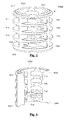
FIG.1 is a view in perspective of an assembly of a sensor unit with a coupling device according to an embodiment of the invention; -
FIG.2 is a side view of an assembly of a sensor unit with a coupling device according to an embodiment of the invention; -
FIG.3 is a view in perspective of a coupling device according to an embodiment of the invention; -
FIG.4 is a view in perspective of the inside of a coupling device according to an embodiment of the invention; -
FIG.5 is a side view of a sensor unit adapted to be fastened to a coupling device according to an embodiment of the invention; and -
FIG.6 is a view from a bottom perspective of an assembly of a sensor unit with a coupling device according to an embodiment of the invention. - The coupling device according to the invention is remarkable in that it enables to solve two problems simultaneously, by means of at least one supporting portion which will maintain the sensor unit in a stable position when resting on or buried into the ground, while a rod or rods linking both supporting portions will provide an additional stiffness to the sensor unit's housing.
-
FIG.1 and FIG.2 disclose a coupling device TRM for a sensor unit SU comprising at least one sensor located within a housing SH, which coupling device TRM includes in this embodiment four rods of which only a first and a second rods RD1 and RD2 are shown here. - The sensor may be a one vertical component digital sensor or a three orthogonal component digital sensor like a geophone or an accelerometer.
- The coupling device TRM features a first supporting portion SP1 featuring a groove supporting an O-ring ORG against which a shoulder portion HSD of the housing SH is pressed by fastening means FSM, which will be described in more detail hereinafter. The coupling device TRM features a second supporting portion SP2 having in this example a circular peripheral section essentially parallel to a peripheral section of the first supporting portion SP1, said first and second supporting portions SP1 and SP2 being linked together by the rods.
- The O-ring may alternately be included in the fastening means FSM . In this case, the coupling device is hardly force-fitted against the shoulder portion HSD of the housing SH.
- In the specific embodiment shown here, the housing SH features a cylindrical pod CSH protruding from the housing's bottom, the end of said pod CSH being fastened to a third supporting portion SP3 by the fastening means FSM, said third supporting portion SP3 being essentially parallel to the first supporting portion SP1. In this embodiment, sensor is located inside the cylindrical pod CSH.
- The second supporting portion SP2 is to be placed on a hard ground in operational conditions. In this case, hard ground does not allow to bury the sensor unit in the ground. The sensor unit will thus be maintained in a stable position when the assembly of the sensor unit SU with the coupling device rests on the ground, while the rods linking both supporting portions SP1 and SP2 will provide an additional stiffness to the sensor unit's housing SH, and will thus prevent the pod from entering into resonance, which will hence significantly increase the operational performance of the sensor unit.
-
FIG.3 and FIG.4 are more detailed views of the coupling device TRM showing its four rods RD1, RD2, RD3 and RD4. - In this embodiment, the coupling device TRM further includes three rows of partially peripheral fins Fij (for i=1 to 4 and j=1 to 3) arranged in parallel with the peripheral of the first and second supporting portions sections SP1 and SP2.
- As explained above, the use of multiple rods amplifies the stiffening effect produced by the coupling device, which effect will be yet again magnified by the fins. A further reason for using a combination of rods and fins instead of a plain shape like a cylinder lies in the spaces separating said fins and rods, which allow loose soil like mud or sand to flow within the space delimited by the external surface of the coupling device. The filling of this space will simultaneously produce a double advantage, since it will help anchor the coupling device on or even within the ground, and it will allow direct contact between the ground and the housing, which will enhance the performance of the sensor.
- As shown in
FIG.3 , the fins Fi3 (for i=1 to 4) of the bottom row can be connected together so as to form the third supporting portion SP3 to which the end of the housing's bottom pod is to be fastened. In this embodiment, the first supporting portion SP1 is provided with a groove which will be located between the coupling device TRM and the housing. This groove supports an O-ring ORG which allows to compensate any clearance between the third supporting portion SP3 and the end of the housing, thus ensuring that the housing and the coupling device are firmly fastened to each other. The hardness value of the O-ring ORG may for example be 90 Shore A. - In this specific embodiment of the invention, the bottom part of the second supporting portion SP2 includes dampening means DMP, formed by an annular protuberance of said second supporting portion SP2. Provided that a material having some elasticity is chosen for producing the coupling device TRM, like for example a 6 66 polyamide loaded at 30% in fiberglass, with an elasticity modulus around 5300 MPa, the annular protuberance will be able to behave like a shock absorber in case of an impact of the bottom of bottom of the coupling device TRM with a hard surface, and thus preserve the physical integrity of the sensor. In other embodiments, an annular piece of an elastic material like rubber could be used as dampening means.
- According to a variant of the above described specific embodiment, the third supporting portion SP3 includes a through hole THL intended to be passed through by screwing means for fastening the end of the housing to the third supporting portion SP3.
-
FIG.5 and FIG.6 illustrate a possible embodiment of the screwing means, in which the end HSE of the pod CSH is provided with a male thread PMT intended to protrude through the hole included in the third supporting portion SP3 of the coupling device, which male thread will then be complemented by a nut NT pressing against the bottom side of the third portion SP3. - In other embodiments not shown here, the screwing means may be formed by providing the end HSE of the pod CSH with a female thread, which will then be completed by a screw whose head will press against the bottom side of the third portion SP3.
- Advantageously, the male or female treads featured by the end HSE of the pod CSH will also be compatible with complementary threads featured at the end of a spike as described in the introduction of the present patent application.
- In the embodiment shown in
FIG.6 , the coupling device TRM features holes H1, H2, H3 and H4, which allow loose soil like mud or sand to flow enter from the bottom surface of the third supporting portion SP3 into the space delimited by the external surface of the coupling device TRM. - The above-described invention ensures that the sensor unit will remain stable even when it is used in loose soil or on hard ground into which it is impossible to drive a spike.
- When the sensor unit equipped with a coupling device according to the invention is operating while placed on or buried into the ground, the coupling device ensures good stability of the sensor.
Claims (14)
- Coupling device for a sensor unit comprising at least one sensor located within a housing, which coupling device includes at least one supporting portion and at least one rod, arranged in a plane which is essentially perpendicular to a peripheral surface of the supporting portion and linked to said supporting portion, said coupling device further including connecting means for connecting the sensor unit to the coupling device.
- Coupling device according to claim 1, having a symmetric shape with respect to at least one plane which is essentially perpendicular with respect to the supporting portion.
- Coupling device according to claims 1 to 2, featuring at least a first supporting portion against which said housing is to be maintained in position and a second supporting portion having a peripheral section essentially parallel to a peripheral section of the first supporting portion, said first and second supporting portions being linked together by said at least one rod.
- Coupling device according to claims 1 to 3, including at least two rods linking together said first and second supporting portions, and at least one partially peripheral fin arranged in parallel with at least one peripheral section of the first and second supporting portions.
- Coupling device according to claims 1 to 4, featuring a third supporting portion upon which an end of the housing is to be fastened, said third supporting portion being placed between the first and second supporting portions.
- Coupling device according to claims 1 to 5, wherein the first supporting portion is provided with a groove supporting an O-ring and intended to be located between the coupling device and the housing.
- Coupling device according to claims 5 or 6, wherein the third supporting portion includes a through hole intended to be passed through by screwing means for fastening the end of the housing to the third supporting portion.
- Coupling device according to claims 1 to 7, wherein a bottom part of the second supporting portion includes dampening means.
- Coupling device according to claims 1 to 8, wherein each peripheral section of a supporting portion has a circular shape.
- Sensor unit adapted to be fastened to a coupling device according to claims 1 to 9.
- Sensor unit according to claim 10, wherein said at least one sensor is a one vertical component digital sensor.
- Sensor unit according to claim 10, wherein said at least one sensor is a three orthogonal component digital sensor.
- Sensor unit according to claim 12, wherein said at least one sensor is a digital geophone or a digital accelerometer.
- Sensor unit according to claims 10 to 13, wherein said at least one sensor is a digital seismic sensor.
Priority Applications (6)
| Application Number | Priority Date | Filing Date | Title |
|---|---|---|---|
| EP12306235.8A EP2720068A1 (en) | 2012-10-09 | 2012-10-09 | Coupling device for seismic sensors |
| CA2827016A CA2827016A1 (en) | 2012-10-09 | 2013-09-13 | Coupling device for seismic sensors |
| CN201310437319.6A CN103713313B (en) | 2012-10-09 | 2013-09-24 | Coupling device for seismic wave sensors |
| RU2013145060A RU2621453C2 (en) | 2012-10-09 | 2013-10-08 | Connecting device for seismic sensors |
| US14/049,580 US9494449B2 (en) | 2012-10-09 | 2013-10-09 | Coupling device for seismic sensors |
| US15/276,047 US10018740B2 (en) | 2012-10-09 | 2016-09-26 | Coupling device for seismic sensors |
Applications Claiming Priority (1)
| Application Number | Priority Date | Filing Date | Title |
|---|---|---|---|
| EP12306235.8A EP2720068A1 (en) | 2012-10-09 | 2012-10-09 | Coupling device for seismic sensors |
Publications (1)
| Publication Number | Publication Date |
|---|---|
| EP2720068A1 true EP2720068A1 (en) | 2014-04-16 |
Family
ID=47148684
Family Applications (1)
| Application Number | Title | Priority Date | Filing Date |
|---|---|---|---|
| EP12306235.8A Withdrawn EP2720068A1 (en) | 2012-10-09 | 2012-10-09 | Coupling device for seismic sensors |
Country Status (5)
| Country | Link |
|---|---|
| US (2) | US9494449B2 (en) |
| EP (1) | EP2720068A1 (en) |
| CN (1) | CN103713313B (en) |
| CA (1) | CA2827016A1 (en) |
| RU (1) | RU2621453C2 (en) |
Cited By (1)
| Publication number | Priority date | Publication date | Assignee | Title |
|---|---|---|---|---|
| US11275327B2 (en) | 2010-06-11 | 2022-03-15 | Ricoh Company, Ltd. | Information storage system including a plurality of terminals |
Families Citing this family (9)
| Publication number | Priority date | Publication date | Assignee | Title |
|---|---|---|---|---|
| EP3117076A4 (en) | 2014-03-10 | 2017-12-06 | Geophysical Technology Inc. | Geophysical sensor mounting with improved ground coupling |
| DE102015202781A1 (en) * | 2015-02-17 | 2016-08-18 | Robert Bosch Gmbh | sensor device |
| DE102015202780A1 (en) * | 2015-02-17 | 2016-08-18 | Robert Bosch Gmbh | sensor device |
| WO2016132171A1 (en) * | 2015-02-18 | 2016-08-25 | Cgg Services Sa | Buried seismic sensor and method |
| USD859197S1 (en) * | 2017-03-17 | 2019-09-10 | Sofar Ocean Technologies, Inc. | Marine sensor platform |
| RU191012U1 (en) * | 2019-02-13 | 2019-07-18 | Общество с ограниченной ответственностью "Сейсмик Тест Инструментс" | Device for binding a seismic sensor to the ground |
| CN113376621B (en) * | 2021-05-26 | 2023-04-07 | 哈尔滨工程大学 | Ice-based underwater sound source detection device and detection method thereof |
| CN114509804A (en) * | 2022-03-07 | 2022-05-17 | 深圳绿灯侠新能源有限公司 | An anti-breakdown detector for solar cells based on supercapacitors |
| FR3165619A1 (en) * | 2025-02-03 | 2026-02-20 | Sercel | Wave signal acquisition device, preferably a seismic acquisition device |
Citations (3)
| Publication number | Priority date | Publication date | Assignee | Title |
|---|---|---|---|---|
| WO1996010195A1 (en) * | 1994-09-27 | 1996-04-04 | Augusto Tonelli | Security apparatus, particularly for protecting the perimeters of sites |
| US6307808B1 (en) * | 2000-02-01 | 2001-10-23 | Lesley J. Schmidt | Methods and apparatuses for seismic prospecting |
| GB2450789A (en) * | 2007-07-04 | 2009-01-07 | Sercel Rech Const Elect | Insertion spike for coupling a seismic sensor to the ground |
Family Cites Families (10)
| Publication number | Priority date | Publication date | Assignee | Title |
|---|---|---|---|---|
| SU1394187A1 (en) * | 1986-04-14 | 1988-05-07 | Организация П/Я А-1209 | Seismoreceiver |
| US5010531A (en) * | 1989-10-02 | 1991-04-23 | Western Atlas International, Inc. | Three-dimensional geophone |
| GB9619699D0 (en) * | 1996-09-20 | 1996-11-06 | Geco Prakla Uk Ltd | Seismic sensor units |
| US6262945B1 (en) * | 1999-04-09 | 2001-07-17 | Syntron, Inc. | Seismic signal coupling device and method |
| WO2003032010A2 (en) * | 2001-10-10 | 2003-04-17 | The Johns Hopkins University | Digital geophone system |
| GB2399171B (en) * | 2003-03-07 | 2006-08-23 | Westerngeco Seismic Holdings | Coupling aid for seismic cable |
| CN100557462C (en) * | 2007-06-18 | 2009-11-04 | 中南大学 | Geophone tailstock for seismic exploration |
| US8611191B2 (en) * | 2008-05-22 | 2013-12-17 | Fairfield Industries, Inc. | Land based unit for seismic data acquisition |
| CN201383007Y (en) * | 2009-03-24 | 2010-01-13 | 罗淳 | Micro-earthquake sensor fixing and withdrawing device |
| US8520469B2 (en) * | 2009-10-12 | 2013-08-27 | Westerngeco L.L.C. | Sensor assembly having a seismic sensor, pressure sensor, and processor to apply first and second digital filters |
-
2012
- 2012-10-09 EP EP12306235.8A patent/EP2720068A1/en not_active Withdrawn
-
2013
- 2013-09-13 CA CA2827016A patent/CA2827016A1/en not_active Abandoned
- 2013-09-24 CN CN201310437319.6A patent/CN103713313B/en not_active Expired - Fee Related
- 2013-10-08 RU RU2013145060A patent/RU2621453C2/en not_active IP Right Cessation
- 2013-10-09 US US14/049,580 patent/US9494449B2/en not_active Expired - Fee Related
-
2016
- 2016-09-26 US US15/276,047 patent/US10018740B2/en not_active Expired - Fee Related
Patent Citations (4)
| Publication number | Priority date | Publication date | Assignee | Title |
|---|---|---|---|---|
| WO1996010195A1 (en) * | 1994-09-27 | 1996-04-04 | Augusto Tonelli | Security apparatus, particularly for protecting the perimeters of sites |
| US6307808B1 (en) * | 2000-02-01 | 2001-10-23 | Lesley J. Schmidt | Methods and apparatuses for seismic prospecting |
| GB2450789A (en) * | 2007-07-04 | 2009-01-07 | Sercel Rech Const Elect | Insertion spike for coupling a seismic sensor to the ground |
| FR2918462A1 (en) | 2007-07-04 | 2009-01-09 | Sercel Sa | SEISMIC SENSOR COMPRISING A PLANTAGE PLANTA BODY AND POINT HAVING AT LEAST TWO WINGS BETWEEN CAVITIES, AND CORRESPONDING TILT POINT |
Cited By (1)
| Publication number | Priority date | Publication date | Assignee | Title |
|---|---|---|---|---|
| US11275327B2 (en) | 2010-06-11 | 2022-03-15 | Ricoh Company, Ltd. | Information storage system including a plurality of terminals |
Also Published As
| Publication number | Publication date |
|---|---|
| US20170010371A1 (en) | 2017-01-12 |
| US10018740B2 (en) | 2018-07-10 |
| CN103713313B (en) | 2017-08-25 |
| RU2621453C2 (en) | 2017-06-06 |
| US20140098631A1 (en) | 2014-04-10 |
| CA2827016A1 (en) | 2014-04-09 |
| CN103713313A (en) | 2014-04-09 |
| US9494449B2 (en) | 2016-11-15 |
| RU2013145060A (en) | 2015-04-20 |
Similar Documents
| Publication | Publication Date | Title |
|---|---|---|
| US10018740B2 (en) | Coupling device for seismic sensors | |
| US8611191B2 (en) | Land based unit for seismic data acquisition | |
| US11243182B2 (en) | Moisture soil probe system | |
| RU2529822C2 (en) | System and device of receiving coil with double suspension | |
| US8000171B2 (en) | Seismic sensor housing | |
| US20160124104A1 (en) | Apparatus and method for 3d seismic exploration for use in a small ship | |
| US9500247B2 (en) | Pounding tune mass damper with viscoelastic material | |
| US20150124562A1 (en) | Wellbore Signal Monitor with Tangential Seismic Sensors for Tube-Wave Noise Reduction | |
| US20140328144A1 (en) | Casing for acoustic coupling with a substrate in seismic investigations | |
| US7730786B2 (en) | Seismic sensor providing a body and an insertion tip having at least two wings between which cavities extend, and corresponding insertion tip | |
| KR101227927B1 (en) | Geophone comprising removable geophone cone with sliding type | |
| KR101250301B1 (en) | Geophone | |
| US10371850B2 (en) | Neutrally buoyant magnetic sensor for borehole magnetometer | |
| CN203412574U (en) | Shock absorption and noise reduction structure for acoustic logging instrument | |
| CN107478216B (en) | Space attitude measurement device, microseismic monitoring system and method | |
| CN115755164A (en) | Detachable 'two-wing precession type' geophone caudal vertebra | |
| JP2001254779A (en) | Damping structure | |
| Yang et al. | Evaluation of the uW finite method in anisotropic porous media | |
| RU2362063C1 (en) | Tapered equifrequent element | |
| CN109143323B (en) | A three-component geophone housing with convertible tail vertebrae | |
| CN206147111U (en) | Distributing type slip coupling wave detector base | |
| RU2362066C1 (en) | Vibration isolator spring by kochetov | |
| US20160356902A1 (en) | Coupling Assembly | |
| RU2362062C1 (en) | Resilient spring element by kochetov | |
| RU2362061C1 (en) | Resilient spring element |
Legal Events
| Date | Code | Title | Description |
|---|---|---|---|
| PUAI | Public reference made under article 153(3) epc to a published international application that has entered the european phase |
Free format text: ORIGINAL CODE: 0009012 |
|
| AK | Designated contracting states |
Kind code of ref document: A1 Designated state(s): AL AT BE BG CH CY CZ DE DK EE ES FI FR GB GR HR HU IE IS IT LI LT LU LV MC MK MT NL NO PL PT RO RS SE SI SK SM TR |
|
| AX | Request for extension of the european patent |
Extension state: BA ME |
|
| 17P | Request for examination filed |
Effective date: 20140423 |
|
| RBV | Designated contracting states (corrected) |
Designated state(s): AL AT BE BG CH CY CZ DE DK EE ES FI FR GB GR HR HU IE IS IT LI LT LU LV MC MK MT NL NO PL PT RO RS SE SI SK SM TR |
|
| STAA | Information on the status of an ep patent application or granted ep patent |
Free format text: STATUS: THE APPLICATION IS DEEMED TO BE WITHDRAWN |
|
| 18D | Application deemed to be withdrawn |
Effective date: 20180501 |