EP2719958A2 - Air conditioner - Google Patents
Air conditioner Download PDFInfo
- Publication number
- EP2719958A2 EP2719958A2 EP13159100.0A EP13159100A EP2719958A2 EP 2719958 A2 EP2719958 A2 EP 2719958A2 EP 13159100 A EP13159100 A EP 13159100A EP 2719958 A2 EP2719958 A2 EP 2719958A2
- Authority
- EP
- European Patent Office
- Prior art keywords
- discharge
- operation panel
- discharge part
- air conditioner
- region
- Prior art date
- Legal status (The legal status is an assumption and is not a legal conclusion. Google has not performed a legal analysis and makes no representation as to the accuracy of the status listed.)
- Withdrawn
Links
Images


Classifications
-
- F—MECHANICAL ENGINEERING; LIGHTING; HEATING; WEAPONS; BLASTING
- F24—HEATING; RANGES; VENTILATING
- F24F—AIR-CONDITIONING; AIR-HUMIDIFICATION; VENTILATION; USE OF AIR CURRENTS FOR SCREENING
- F24F13/00—Details common to, or for air-conditioning, air-humidification, ventilation or use of air currents for screening
- F24F13/08—Air-flow control members, e.g. louvres, grilles, flaps or guide plates
- F24F13/10—Air-flow control members, e.g. louvres, grilles, flaps or guide plates movable, e.g. dampers
-
- F—MECHANICAL ENGINEERING; LIGHTING; HEATING; WEAPONS; BLASTING
- F24—HEATING; RANGES; VENTILATING
- F24F—AIR-CONDITIONING; AIR-HUMIDIFICATION; VENTILATION; USE OF AIR CURRENTS FOR SCREENING
- F24F1/00—Room units for air-conditioning, e.g. separate or self-contained units or units receiving primary air from a central station
- F24F1/0007—Indoor units, e.g. fan coil units
- F24F1/0011—Indoor units, e.g. fan coil units characterised by air outlets
-
- F—MECHANICAL ENGINEERING; LIGHTING; HEATING; WEAPONS; BLASTING
- F24—HEATING; RANGES; VENTILATING
- F24F—AIR-CONDITIONING; AIR-HUMIDIFICATION; VENTILATION; USE OF AIR CURRENTS FOR SCREENING
- F24F1/00—Room units for air-conditioning, e.g. separate or self-contained units or units receiving primary air from a central station
- F24F1/0007—Indoor units, e.g. fan coil units
- F24F1/0043—Indoor units, e.g. fan coil units characterised by mounting arrangements
- F24F1/005—Indoor units, e.g. fan coil units characterised by mounting arrangements mounted on the floor; standing on the floor
-
- F—MECHANICAL ENGINEERING; LIGHTING; HEATING; WEAPONS; BLASTING
- F24—HEATING; RANGES; VENTILATING
- F24F—AIR-CONDITIONING; AIR-HUMIDIFICATION; VENTILATION; USE OF AIR CURRENTS FOR SCREENING
- F24F1/00—Room units for air-conditioning, e.g. separate or self-contained units or units receiving primary air from a central station
- F24F1/0007—Indoor units, e.g. fan coil units
- F24F1/0018—Indoor units, e.g. fan coil units characterised by fans
- F24F1/0033—Indoor units, e.g. fan coil units characterised by fans having two or more fans
Definitions
- the present disclosure relates to an air conditioner.
- Air conditioners are home appliances that maintain indoor air into the most proper state according to use and purpose thereof. For example, such an air conditioner controls indoor air into a cold state in summer and controls indoor air into a warm state in winter. Furthermore, the air conditioner controls humidity of the indoor air and purifies the indoor air to become into a pleasant and clean state. Air conditioners may have a refrigeration cycle constituted by a compressor, a condenser, an expansion device, and an evaporator.
- Such an air conditioner may be classified into a split type air conditioner in which indoor and outdoor units are separated from each other and an integral type air conditioner in which indoor and outdoor units are integrally coupled to each other as a single device, according to whether the indoor and outdoor units are separated from each other.
- Air conditioners are classified into a wall-mounted type air conditioner mounted on a wall, a frame type air conditioner, and a slim type air conditioner standing in the living room according to an installation method.
- Such an air conditioner includes a suction part for suctioning air within an indoor space, a heat exchanger heat-exchanged with the air suctioned through the suction part, and a discharge part for discharging the air heat-exchanged in the heat exchanger into the indoor space.
- the air conditioner may include a blower fan for generating an airflow from the suction part to the discharge part.
- the discharge part is provided in plurality, since the amount of air discharged through each of the discharge parts is equally adjusted, it may be difficult to increase or decrease the discharge amount of air in a specific direction.
- Embodiments of the invention provide an air conditioner in which a discharge direction and/or discharge amount of air can be effectively adjusted.
- an air conditioner includes: a case; a first discharge part disposed on side of the case to discharge air; a second discharge part disposed on the other side of the case to discharge air; and an operation panel movably disposed on the case to cover at least portions of the first and second discharge parts, wherein, while the operation panel is moved, the first and second discharge parts have the same air discharge area and a variable discharge region.
- an air conditioner in another embodiment, includes: a case; a discharge part disposed on the case to discharge air; and an operation panel disposed movable from one direction toward the other direction on a side of the case to open at least one portion of the discharge part, wherein an air discharge region of the whole region of the discharge part is varied according to the movement of the operation panel.
- an air conditioner includes: a case; a discharge part disposed on the case to discharge air; and an operation panel disposed on a side of the discharge part, wherein the operation panel is movable from a first position at which one region of the discharge part is covered toward a second position at which the other region of the discharge part is covered.
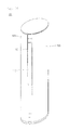
- Fig. 1 is a perspective view of an air conditioner in which a discharge panel is opened according to the first embodiment.
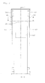
- Fig. 2 is a front view of the air conditioner in which the discharge panel is opened according to the first embodiment.
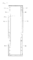
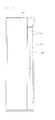
- Fig. 3 is a cross-sectional view taken along line I-I' of Fig. 2 .
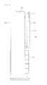
- Fig. 4 is a cross-sectional view taken along line II-II' of Fig. 2 .
- Fig. 5 is a view of the air conditioner in a state where an operation panel is moved in one direction according to the first embodiment.
- Fig. 6 is a view of the air conditioner in a state where the operation panel is moved in the other direction according to the first embodiment.
- Fig. 7 is a front view of an air conditioner in which both discharge parts are opened according to a second embodiment.
- Fig. 8 is a front view of the air conditioner in which a first discharge part is opened according to the second embodiment.
- Fig. 9 is a front view of the air conditioner in which a second discharge part is opened according to the second embodiment.
- Fig. 10 is a perspective view of an air conditioner according to a third embodiment.
- Fig. 11 is a front view of the air conditioner according to the third embodiment.
- Fig. 12 is a view of the air conditioner in which an operation panel is moved in one direction according to the third embodiment.
- Fig. 13 is a view of the air conditioner in which the operation panel is moved in the other direction according to the third embodiment.
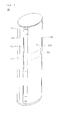
- Fig. 1 is a perspective view of an air conditioner in which a discharge panel is opened according to the first embodiment.
- Fig. 2 is a front view of the air conditioner in which the discharge panel is opened according to the first embodiment.
- an air conditioner 10 includes a case 100 defining an inner space, a movable operation panel 200 disposed on a front side of the case 100, and movable discharge panels 310 and 320 disposed on at least one side of the operation panel 200.
- the case 100 has a rounded outer appearance. Also, the case 100 may have an approximately oval shape on the whole.
- An outer appearance of a front or side surface of the air conditioner 10 may be defined by the operation panel 200 or the discharge panels 310 and 320. At least portions of the operation panel 200 and the discharge panels 310 and 320 may be rounded to correspond to that of the case 100.
- An input part 205 through which a user inputs a command is disposed on the operation panel 200.
- the input part 205 may be a power input part for turning on/off a power of the air conditioner 10.
- a display part 250 for displaying information related to an operation state of the air conditioner 10 is disposed on the operation panel 200.
- the display part 250 may be hidden when the air conditioner 10 is turned off and be exposed to the outside when the input part 205 is manipulated to turn on the air conditioner 10.
- the discharge panels 310 and 320 include a first discharge panel 310 provided on one side of the operation panel 200 and a second discharge panel 320 provided on the other side of the operation panel 200.
- the first discharge panel 310 and the second discharge panel 320 may be moved in a direction toward or away from the operation panel 200.
- the air conditioner 10 includes discharge parts 110 and 120 through which air is discharged. Also, the discharge parts 110 and 120 are disposed on both front surfaces of the case 100, respectively. A discharge grill for preventing foreign substances from being introduced or discharged may be disposed in each of the discharge parts 110 and 120.
- the discharge parts 110 and 120 include a first discharge part 110 disposed on one side of the operation panel 200 and a second discharge part 120 disposed on the other side of the operation panel 200.
- the first and second discharge parts 110 and 120 may be disposed spaced apart from each other.
- the operation panel 200 may cover at least one portion of the first discharge part 110 and at least one portion of the second discharge part 120.
- the operation panel 200 is disposed between the first discharge part 110 and the second discharge part 120 to partition the first discharge part 110 from the second discharge part 120.
- the first discharge panel 310 may selectively open or close the first discharge part 110.
- the first discharge panel 310 may be moved in a direction away from the operation panel 200. In this process, at least one portion of the first discharge part 110 may be opened.
- the first discharge panel 310 may be moved in a direction toward the operation panel 200. In this process, the first discharge part 110 may be covered.
- the second discharge panel 320 may selectively open the second discharge part 120.
- the second discharge panel 320 may be moved in a direction away from the operation panel 200. In this process, at least one portion of the second discharge part 120 may be opened.
- the second discharge panel 320 may be moved in a direction toward the operation panel 200. In this process, the second discharge part 120 may be covered.
- a discharge vane 150 may be movably disposed on each of the first and second discharge parts 110 and 120.
- the discharge vane 150 may be rotatably disposed to adjust a flow direction of air discharged from the first and second discharge parts 110 and 120.
- the discharge vane 150 may be disposed behind the operation panel 200 or the discharge panels 310 and 320.
- the discharge vane 150 When the first or second discharge panel 310 or 320 is opened, the discharge vane 150 is exposed to the outside. Also, when the discharge vane 150 is opened, air may be discharged to the outside through the first or second discharge part 110 or 120.
- the first and second discharge panels 310 and 320 may be moved in both directions, i.e., in directions away from each other.
- the operation panel 200 is disposed at a front central portion of the case 100.
- the first and second panels 310 and 320 are disposed to open front sides of the first and second discharge parts 110 and 120 on both sides of the operation panel 200, respectively.
- the position of the operation panel 200 may be called a "central position” or a "first position".
- the operation panel 200 may cover at least one portion of the first discharge part 110 and at least one portion of the second discharge part 120 at the central position. That is, the operation panel 200 may have a horizontal width greater than a distance between the first discharge part 110 and the second discharge part 120.
- the discharge vane 150 When the first and second discharge panels 310 and 320 are opened, the discharge vane 150 is exposed to the outside. Then, the discharge vane 150 is rotated or moved to open the first discharge part 110 or the second discharge part 120. That is, air may be discharged through both sides of the operation panel 200.
- a flow direction of air discharged from the first and second discharge parts 110 and 120 may be adjusted according to a rotated angle or moving distance of the discharge vane 150.
- the air conditioner 10 When the input part 205 is manipulated while the air conditioner 10 is operated, the air conditioner 10 may be turned off. When the power is turned off, the discharge vane 150 may be disposed to cover the first and second discharge parts 110 and 120.
- first and second discharge panels 310 and 320 are moved toward the operation panel 200 to cover at least portions of the first and second discharge parts 110 and 120.
- first discharge panel 310 may be moved in a counterclockwise direction
- second discharge panel 320 may be moved in a clockwise direction.
- the first and second discharge panels 310 and 320 When the first and second discharge panels 310 and 320 are closed, the first and second panels 310 and 320 may be disposed to approximately contact both sides of the operation panel 200.
- Fig. 3 is a cross-sectional view taken along line I-I' of Fig. 2 .
- Fig. 4 is a cross-sectional view taken along line II-II' of Fig. 2 .
- the case 100 includes a suction part 101 through which air is suctioned and the plurality of discharge parts 110 and 120 through which air is discharged.
- the suction part 101 is disposed in a rear surface of the case 100 to suck air. Also, a heat exchanger 103 and blower fans 105 and 106 are disposed on a front side of the suction part 101.
- the blower fans 105 and 106 may include a first fan 105 and a second fan 106 disposed under the first fan 105.
- the plurality of discharge parts 110 and 120 include the first discharge part 110 disposed at a left side of the operation panel 200 and the second discharge part 120 disposed at a right side of the operation panel 200.
- the first and second discharge parts 110 and 120 may be opened or closed by being linked with each other or independently opened or closed.
- blower fans 105 and 106 When the blower fans 105 and 106 are operated, air is introduced into the case 100 through the suction part 101 to pass through the heat exchanger 103. Then, the air may be branched into the first and second discharge parts 110 and 120 while passing through the first and second fans 105 and 106.
- the air conditioner 10 includes the operation panel 200 and a driving device for moving the discharge panels 310 and 320.
- the driving device includes a driving motor 210 for generating a driving force for moving the operation panel 200, a pinion gear 215 rotated by the operation of the driving motor 210, and a rack gear 201 linked with the pinion gear 215.
- the driving motor 210 is disposed at a rear side of the operation panel 200 and includes a motor shaft 212.
- the pinion gear 215 is connected to the motor shaft 212 and rotated together with the motor shaft 212.
- the rack gear 201 may be disposed on a rear surface of the operation panel 200.
- the driving motor may be a bidirectionally rotatable motor.
- the pinion gear 215 When the driving motor 210 is rotated in one direction, the pinion gear 215 may be rotated to correspond to the rotation of the driving motor 210. Then, the rack gear 201 may be linked with the pinion gear 215 and thus moved in a clockwise direction (a left side when viewed from a front surface of FIG. 2 ).
- the operation panel 200 may be operated to cover the first discharge part 110.
- the first discharge panel 310 may be in the opened state.
- the pinion gear 215 may be rotated to correspond to the rotation of the driving motor 210. Then, the rack gear 201 may be linked with the pinion gear 215 and thus moved in a counterclockwise direction (a right side when viewed from the front surface of Fig. 2 ).
- the operation panel 200 may be operated to cover the first discharge part 120.
- the second discharge panel 320 may be in the opened state.
- the driving device includes a discharge motor 302 for generating a driving force for moving the discharge panels 310 and 320 and a power transmission member 306 rotated according to an operation of the discharge motor 302.
- the power transmission member 306 may be connected to a motor shaft 304 of the discharge motor 302 and rotated in a clockwise or counterclockwise direction.
- the power transmission member 305 may be a link member.
- the power transmission member 306 may be coupled to a rear surface of each of the discharge panels 310, 320 and 320.
- the discharge motor 302 and the power transmission member 306 may be disposed on both inner sides of the case 100 to move the first and second discharge panels 310 and 320, respectively.
- the discharge motor 302 may be a bidirectionally rotatable motor.
- the power transmission member 306 is rotated in a clockwise direction.
- the first discharge panel 310 is moved to open the first discharge part 110.
- the first discharge panel 310 is operated to close at least one portion of the first discharge part 110, i.e., a first discharge region 111.
- the second discharge panel 320 In the operation of the second discharge panel 320, when the power transmission member 306 is rotated in the counterclockwise direction, the second discharge panel 320 is operated to open the second discharge part 120.
- the second discharge panel 320 is operated to close at least one portion of the second discharge part 120, i.e., a fourth discharge region 123.
- the first discharge part 110 includes a first discharge region 111 and a second discharge region 113 which are selectively covered.
- the first and second discharge regions 111 and 113 define a portion region and a region except the portion region of the first discharge part 110.
- each of the first and second discharge regions 211 and 113 may be understood as a region opened or closed by the discharge vane 150, i.e., a region corresponding to the discharge vane 150.
- the second discharge part 120 includes a third discharge region 121 and a fourth discharge region 123.
- the discharge vane 150 is disposed in a front side of each of the third and fourth discharge regions 121 and 123.
- the second discharge region 113 and the third discharge region 121 are disposed between the first discharge region 111 and the fourth discharge region 123.
- a front side of the third discharge region 121 is covered by the operation panel 200, and a front side of the fourth discharge region 123 is covered by the second discharge panel 320.
- the second and third discharge regions 113 and 121 may be spaced apart from each other. Also, the second and third discharge regions 113 and 121 may be covered at the same time by the operation panel 200. The second and third discharge regions 113 and 121 may be understood as central regions of the first and second discharge parts 110 and 120, respectively.
- the operation panel 200 is disposed at a front central position of the case 100, i.e., the first position to cover the second and third discharge regions 113 and 121.
- the discharge of air through the second and third discharge regions 113 and 121 may be restricted.
- air may be discharged through the first and fourth discharge regions 111 and 123.
- the air may be discharged through the opened discharge regions of both sides of the operation panel 200 in both side directions (see Fig. 2 ). That is to say, the opened regions of the discharge parts 110 and 120 may be disposed on both sides of the operation panel 200.
- an air discharge area of the first and second discharge parts 110 and 120 may be less than the sum of areas of all of the discharge parts 110 and 120.
- Fig. 5 is a view of the air conditioner in a state where an operation panel is moved in one direction according to the first embodiment.
- Fig. 6 is a view of the air conditioner in a state where the operation panel is moved in the other direction according to the first embodiment.
- the operation panel 200 in a state of the first position shown in Fig. 2 , the operation panel 200 may be moved toward the second discharge part 120 from the first discharge part 110, i.e., in a right direction or counterclockwise direction.
- a position of the operation panel 200 may be called a "right position" of a "second position”.
- the operation panel 200 when the operation panel 200 is moved to the second position, the second discharge region 113 is opened. Thus, air may be concentratedly discharged in a left direction of the air conditioner 10.
- the second discharge region 113 may be exposed to the outside. Also, the discharge vane 150 corresponding to the second discharge region 113 may be opened to discharge air from the second discharge region 113. As a result, air may be discharged through the first and second discharge regions 111 and 113, i.e., the whole region of the first discharge part 110.
- an opened area of the first discharge part 110 is increased according to the movement of the operation panel 200, and thus the amount of air discharged through the first discharge part 110 is increased.
- the fourth discharge region 123 is covered by the operation panel 200. That is to say, the second discharge panel 320 may be moved to open at least one portion of the second discharge part 120, i.e., the fourth discharge region 123. Also, the fourth discharge region 123 may be covered by the operation panel 200.
- the third and fourth discharge regions 121 and 123 i.e., the whole of the second discharge part 120 may be closed by the operation panel 200, and thus, the discharge of air through the second discharge part 120 may be restricted.
- the opened area of the second discharge part 120 may be increased according to the movement of the operation panel 200, and thus the amount of air discharged through the second discharge part 120 may be increased.
- air may be concentratedly discharged toward one side (left side) of the operation panel 200.
- the personalized operation of the air conditioner 10 may be allowable according to the installation position of the air conditioner 10 or the position of the user.
- the size of the opened area, through which air is discharged, of the whole region of the first and second discharge parts 110 and 120 may be constant regardless of the first and second position of the operation panel 200. That is, while two discharge regions are closed, other two discharge regions are opened.
- an actual air discharged region of the whole discharge regions 111, 113, 121, and 123 may be restricted to portion regions 111 and 113.
- the air discharge area of the first and second discharge parts 110 and 120 may be less than the whole area of the first and second discharge parts 110 and 120.
- the operation panel 200 in a state of the first position shown in Fig. 2 , the operation panel 200 may be moved toward the first discharge part 110 from the second discharge part 120, i.e., in a left direction or a clockwise direction.
- a position of the operation panel 200 may be called a "left position" of a "third position”.
- the operation panel 200 when the operation panel 200 is moved to the third position, the third discharge region 121 is opened. Thus, air may be concentratedly discharged in a right direction of the air conditioner 10.
- the third discharge region 121 may be exposed to the outside. Also, the discharge vane 150 corresponding to the third discharge region 121 may be opened to discharge air from the third discharge region 121. As a result, air may be discharged through the third and fourth discharge regions 121 and 123, i.e., the whole region of the second discharge part 110.
- the opened area of the second discharge part 120 is increased according to the movement of the operation panel 200, and thus the amount of air discharged through the second discharge part 120 is increased.
- the operation panel 200 As the operation panel 200 is moved to the third position, the first discharge region 111 is covered by the operation panel 200. As a result, the first and second discharge regions 111 and 113, i.e., the whole of the first discharge part 110 may be closed by the operation panel 200, and thus, the discharge of air through the first discharge part 110 may be restricted.
- the opened area of the first discharge part 110 may be increased according to the movement of the operation panel 200, and thus the amount of air discharged through the first discharge part 110 may be increased. Thus, air may be concentratedly discharged toward the other side (right side) of the operation panel 200.
- air may be concentratedly discharged toward the other side of the air conditioner 10 according to the position of the operation panel 200, and thus the personalized operation of the air conditioner 10 may be allowable according to the installation position of the air conditioner 10 or the position of the user.
- the air discharge region or the opened area of the whole region of the first and second discharge parts 110 and 120 may be constant regardless of the first or third position of the operation panel 200.
- an actual air discharge region of the whole discharge regions 111, 113, 121, and 123 may be restricted to portion regions 121 and 123.
- the air discharge area of the first and second discharge parts 110 and 120 may be less than the whole area of the first and second discharge parts 110 and 120.
- the operation panel 200 is moved from the first position to the second position or from the first position to the third position, the present disclosure is not limited thereto.
- the operation panel 200 may be moved from the second position to the first position or from the third position to the first position.
- the operation panel 200 may be moved from the second position to the third position or from the third position to the second position.
- the second embodiment is equal to the first embodiment except a configuration of a suction part.
- the same parts as those of the first embodiment will be denoted by the same description and reference numeral.
- Fig. 7 is a front view of an air conditioner in which both discharge parts are opened according to a second embodiment.
- Fig. 8 is a front view of the air conditioner in which a first discharge part is opened according to the second embodiment.
- Fig. 9 is a front view of the air conditioner in which a second discharge part is opened according to the second embodiment.
- an air conditioner 2 includes suction parts 401 and 402 disposed in a front surface of a case (see a reference number 100 of Fig. 1 ).
- the suction parts 401 and 402 include a first suction part 401 disposed in one side of the case 100 and a second suction part 402 disposed in the other side of the case 100.
- the first suction part 401 may be disposed under the first discharge part 110
- the second suction part 402 may be disposed under the second discharge part 120.
- Air introduced into a lower side of the case 100 through the suction parts 401 and 402 is heat-exchanged while the air is moved upward.
- the heat-exchanged air may be discharged to the outside through the first or second discharge part 110 or 120.
- a heat exchanger or a blower may be disposed within the case 100.
- the first and second suction parts 401 and 402 may be disposed on both sides of an operation panel 200.
- the operation panel 200 may selectively open or close the first or second suction part 401 or 402.
- the operation panel 200 may be moved from the first suction part 401 toward the second suction part 402 or from the second suction part 402 toward the first suction part 401.
- the operation panel 200 may open the first suction part 401 when the first discharge part 110 is opened and open the second suction part 402 when the second discharge 120 is opened.
- the first suction part 401 may be covered also by the operation panel 200.
- the second suction part 402 may be covered also by the operation panel 200.
- the operation panel 200 when the operation panel 200 is disposed at a central position of the operation panel 200, at least one portion of a discharge region of the first discharge part 100 and at least one portion of a suction region of the first suction part 401 may be covered by the operation panel 200.
- the operation panel 200 may be disposed or moved to open or close the discharge parts 110 and 120 or the suction parts 401 and 402 at the same time.
- Fig. 7 illustrates the air conditioner in which a first discharge panel 310 and a second discharge panel 320 are opened.
- the first and second discharge panels 310 and 320 may be moved in directions to approach each other to close the discharge parts 110 and 120 and the suction parts 401 and 402.
- both discharge panels 310 and 320 may be opened in a state where the operation panel 200 is disposed at a central position (a first position). In this process, the first and second discharge panels 310 and 320 may be moved in directions away from each other.
- At least one portion of the first suction part 401 and at least one portion of the second suction part 402 may be opened to suction air in both directions.
- Air heat-exchanged within the case 100 may be discharged to the outside through the first discharge region 111 of the first discharge part 110 and the fourth discharge region 123 of the second discharge part 120.
- the operation panel 200 is disposed to open (or close) a portion of each of the first and second suction parts 401 and 402 and a portion of each of the first and second discharge parts 110 and 120.
- the operation panel 200 when the operation panel 200 is disposed at a right position (a second position), the first suction part 401 and the first discharge part 110 may be fully opened, and the second suction part 402 and the second discharge part 120 may be fully closed.
- air may be suctioned through the first suction part 401 and discharged through the first discharge part 110.
- a flow direction of the discharged air may be adjusted according to the movement of the discharge vane 150.
- the second suction part 402 and the second discharge part 120 may be fully opened, and the first suction part 401 and the first discharge part 110 may be fully closed.
- air may be suctioned through the second suction part 402 and discharged through the second discharge part 120.
- a flow direction of the discharged air may be adjusted according to the movement of the discharge vane 150.
- the suction and discharge directions of the air may be adjusted according to the movement of the operation panel 200, a user personalized operation of the air conditioner may be enabled.
- Fig. 10 is a perspective view of an air conditioner according to a third embodiment
- Fig. 11 is a front view of the air conditioner according to the third embodiment
- Fig. 12 is a view of the air conditioner in which an operation panel is moved in one direction according to the third embodiment
- Fig. 13 is a view of the air conditioner in which the operation panel is moved in the other direction according to the third embodiment.
- an air conditioner 10 includes a case 100 defining an inner space and a movable operation panel 200 disposed on a front side of the case 100.
- the current embodiment is characterized in that the discharge panel is omitted.
- the air conditioner 10 includes discharge parts 110 and 120 respectively disposed on both sides of a front surface of the case 100.
- the discharge parts 110 and 120 include a first discharge part disposed on one side of the operation panel 200 and a second discharge part 120 disposed on the other side of the operation panel 200.
- the operation panel 200 may be disposed to cover at least one portion of the first discharge part 110 and at least one portion of the second discharge part 120.
- a second discharge region 113 of the first discharge part 110 and a third discharge region 121 of the second discharge part 120 are covered by the operation panel 200.
- a first discharge region 111 of the first discharge part 110 and a fourth discharge region 123 of the second discharge part 120 may be shown to the outside in a state where the first and fourth discharge regions 111 and 123 are covered by a discharge vane 150.
- the operation panel 200 may be in a state of Fig. 11 .
- the state of the operation panel 200 as shown in Fig. 11 may be called a "default state".
- the operation panel 200 when the operation panel 200 is disposed at the first position while the air conditioner 10 is turned on and operated, air may be discharged in both directions of the case 100 through the first and second discharge parts 110 and 120.
- the discharge vane 150 is opened.
- the operation panel 200 may be disposed at a front right position (a second position) of the case 100. That is, the operation panel 200 may be moved in a right direction from the first position of Fig. 11 .
- the state of the operation panel 200 as shown in Fig. 12 may be called a "first operation state".
- the whole region of the first discharged part 110 i.e., the first and second discharge regions 111 and 113 may be opened.
- air may be concentratedly discharged in a left direction of the air conditioner 10 through the first and second discharge regions 111 and 113.
- the discharge vane 150 disposed in the first and second discharge regions 111 and 113 may be opened.
- the whole region of the second discharge part 120 i.e., the third and fourth discharge regions 121 and 123 may be covered by the operation panel 200.
- the discharge of the air through the second discharge part 120 may be restricted.
- the operation panel 200 may be disposed at a front left position (a third position) of the case 100. That is, the operation panel 200 may be moved in a left direction from the first position of Fig. 11 .
- the state of the operation panel 200 as shown in Fig. 13 may be called a "second operation state".
- the whole region of the second discharge part 120 i.e., the third and fourth discharge regions 121 and 123 may be opened.
- air may be concentratedly discharged in a right direction of the air conditioner 10 through the third and fourth discharge regions 121 and 123.
- the discharge vane 150 disposed in the third and fourth regions 121 and 123 may be opened.
- the whole region of the first discharge part 110 i.e., the first and second discharge regions 111 and 113 may be covered by the operation panel 200.
- the discharge of the air through the first discharge part 110 may be restricted.
- the discharge region through the discharge part may be varied according to the movement of the operation panel.
- the discharge region may be adequately adjusted according to the position of the user or the installation position of the air conditioner.
- cool air may be discharged toward the front side or concentratedly discharged according to the position or tastes of the user, the personalized operation of the air conditioner may be enabled.
- the discharge part may be provided on each of both sides of the operation panel, and the discharge direction and amount of air may be adjusted while the operation panel is slid from one discharge part to the other discharge part, the discharge method may be simply adjusted.
- the discharge method of air may be controlled by manipulating only the operation panel, the convenience of manipulation may be increased.
- the discharge part When the air conditioner is not operated, the discharge part may be covered by the operation panel and the discharge panel to realize the elegant outer appearance.
Landscapes
- Engineering & Computer Science (AREA)
- Chemical & Material Sciences (AREA)
- Combustion & Propulsion (AREA)
- Mechanical Engineering (AREA)
- General Engineering & Computer Science (AREA)
- Air-Flow Control Members (AREA)
- Air Filters, Heat-Exchange Apparatuses, And Housings Of Air-Conditioning Units (AREA)
Abstract
Description
- The present disclosure relates to an air conditioner.
- Air conditioners are home appliances that maintain indoor air into the most proper state according to use and purpose thereof. For example, such an air conditioner controls indoor air into a cold state in summer and controls indoor air into a warm state in winter. Furthermore, the air conditioner controls humidity of the indoor air and purifies the indoor air to become into a pleasant and clean state. Air conditioners may have a refrigeration cycle constituted by a compressor, a condenser, an expansion device, and an evaporator.
- Such an air conditioner may be classified into a split type air conditioner in which indoor and outdoor units are separated from each other and an integral type air conditioner in which indoor and outdoor units are integrally coupled to each other as a single device, according to whether the indoor and outdoor units are separated from each other. Air conditioners are classified into a wall-mounted type air conditioner mounted on a wall, a frame type air conditioner, and a slim type air conditioner standing in the living room according to an installation method.
- Such an air conditioner includes a suction part for suctioning air within an indoor space, a heat exchanger heat-exchanged with the air suctioned through the suction part, and a discharge part for discharging the air heat-exchanged in the heat exchanger into the indoor space. Also, the air conditioner may include a blower fan for generating an airflow from the suction part to the discharge part.
- In the air conditioner according to the related art, air is discharged in a constant direction through the discharge part. In this case, there is a limitation that it is difficult to adequately control the discharge direction of the air according to a position of the user.
- Also, in a case where the discharge part is provided in plurality, since the amount of air discharged through each of the discharge parts is equally adjusted, it may be difficult to increase or decrease the discharge amount of air in a specific direction.
- Embodiments of the invention provide an air conditioner in which a discharge direction and/or discharge amount of air can be effectively adjusted.
- In one embodiment, an air conditioner includes: a case; a first discharge part disposed on side of the case to discharge air; a second discharge part disposed on the other side of the case to discharge air; and an operation panel movably disposed on the case to cover at least portions of the first and second discharge parts, wherein, while the operation panel is moved, the first and second discharge parts have the same air discharge area and a variable discharge region.
- In another embodiment, an air conditioner includes: a case; a discharge part disposed on the case to discharge air; and an operation panel disposed movable from one direction toward the other direction on a side of the case to open at least one portion of the discharge part, wherein an air discharge region of the whole region of the discharge part is varied according to the movement of the operation panel.
- In further another embodiment, an air conditioner includes: a case; a discharge part disposed on the case to discharge air; and an operation panel disposed on a side of the discharge part, wherein the operation panel is movable from a first position at which one region of the discharge part is covered toward a second position at which the other region of the discharge part is covered.
- The details of one or more embodiments are set forth in the accompanying drawings and the description below. Other features will be apparent from the description and drawings, and from the claims.
-
Fig. 1 is a perspective view of an air conditioner in which a discharge panel is opened according to the first embodiment. -
Fig. 2 is a front view of the air conditioner in which the discharge panel is opened according to the first embodiment. -
Fig. 3 is a cross-sectional view taken along line I-I' ofFig. 2 . -
Fig. 4 is a cross-sectional view taken along line II-II' ofFig. 2 . -
Fig. 5 is a view of the air conditioner in a state where an operation panel is moved in one direction according to the first embodiment. -
Fig. 6 is a view of the air conditioner in a state where the operation panel is moved in the other direction according to the first embodiment. -
Fig. 7 is a front view of an air conditioner in which both discharge parts are opened according to a second embodiment. -
Fig. 8 is a front view of the air conditioner in which a first discharge part is opened according to the second embodiment. -
Fig. 9 is a front view of the air conditioner in which a second discharge part is opened according to the second embodiment. -
Fig. 10 is a perspective view of an air conditioner according to a third embodiment. -
Fig. 11 is a front view of the air conditioner according to the third embodiment. -
Fig. 12 is a view of the air conditioner in which an operation panel is moved in one direction according to the third embodiment. -
Fig. 13 is a view of the air conditioner in which the operation panel is moved in the other direction according to the third embodiment. - Reference will now be made in detail to the embodiments of the present disclosure, examples of which are illustrated in the accompanying drawings. The invention may, however, be embodied in many different forms and should not be construed as being limited to the embodiments set forth herein; rather, that alternate embodiments included in other retrogressive inventions or falling within the scope of the present disclosure will fully convey the concept of the invention to those skilled in the art.
-
Fig. 1 is a perspective view of an air conditioner in which a discharge panel is opened according to the first embodiment.Fig. 2 is a front view of the air conditioner in which the discharge panel is opened according to the first embodiment. - Referring to
Figs. 1 and2 , anair conditioner 10 according to a first embodiment includes acase 100 defining an inner space, amovable operation panel 200 disposed on a front side of thecase 100, andmovable discharge panels operation panel 200. - The
case 100 has a rounded outer appearance. Also, thecase 100 may have an approximately oval shape on the whole. - An outer appearance of a front or side surface of the
air conditioner 10 may be defined by theoperation panel 200 or thedischarge panels operation panel 200 and thedischarge panels case 100. - An
input part 205 through which a user inputs a command is disposed on theoperation panel 200. For example, theinput part 205 may be a power input part for turning on/off a power of theair conditioner 10. - Also, a
display part 250 for displaying information related to an operation state of theair conditioner 10 is disposed on theoperation panel 200. Thedisplay part 250 may be hidden when theair conditioner 10 is turned off and be exposed to the outside when theinput part 205 is manipulated to turn on theair conditioner 10. - The
discharge panels first discharge panel 310 provided on one side of theoperation panel 200 and asecond discharge panel 320 provided on the other side of theoperation panel 200. Thefirst discharge panel 310 and thesecond discharge panel 320 may be moved in a direction toward or away from theoperation panel 200. - The
air conditioner 10 includesdischarge parts discharge parts case 100, respectively. A discharge grill for preventing foreign substances from being introduced or discharged may be disposed in each of thedischarge parts - The
discharge parts first discharge part 110 disposed on one side of theoperation panel 200 and asecond discharge part 120 disposed on the other side of theoperation panel 200. The first andsecond discharge parts - The
operation panel 200 may cover at least one portion of thefirst discharge part 110 and at least one portion of thesecond discharge part 120. In detail, theoperation panel 200 is disposed between thefirst discharge part 110 and thesecond discharge part 120 to partition thefirst discharge part 110 from thesecond discharge part 120. - The
first discharge panel 310 may selectively open or close thefirst discharge part 110. In detail, thefirst discharge panel 310 may be moved in a direction away from theoperation panel 200. In this process, at least one portion of thefirst discharge part 110 may be opened. - On the other hand, the
first discharge panel 310 may be moved in a direction toward theoperation panel 200. In this process, thefirst discharge part 110 may be covered. - The
second discharge panel 320 may selectively open thesecond discharge part 120. In detail, thesecond discharge panel 320 may be moved in a direction away from theoperation panel 200. In this process, at least one portion of thesecond discharge part 120 may be opened. - On the other hand, the
second discharge panel 320 may be moved in a direction toward theoperation panel 200. In this process, thesecond discharge part 120 may be covered. - A
discharge vane 150 may be movably disposed on each of the first andsecond discharge parts discharge vane 150 may be rotatably disposed to adjust a flow direction of air discharged from the first andsecond discharge parts discharge vane 150 may be disposed behind theoperation panel 200 or thedischarge panels - When the first or
second discharge panel discharge vane 150 is exposed to the outside. Also, when thedischarge vane 150 is opened, air may be discharged to the outside through the first orsecond discharge part - Hereinafter, an operation of the air conditioner according to the current embodiment will be described simply.
- When a user manipulates the
input part 205 to turn on theair conditioner 10, the first andsecond discharge panels - Here, the
operation panel 200 is disposed at a front central portion of thecase 100. The first andsecond panels second discharge parts operation panel 200, respectively. - Here, the position of the
operation panel 200 may be called a "central position" or a "first position". Theoperation panel 200 may cover at least one portion of thefirst discharge part 110 and at least one portion of thesecond discharge part 120 at the central position. That is, theoperation panel 200 may have a horizontal width greater than a distance between thefirst discharge part 110 and thesecond discharge part 120. - When the first and
second discharge panels discharge vane 150 is exposed to the outside. Then, thedischarge vane 150 is rotated or moved to open thefirst discharge part 110 or thesecond discharge part 120. That is, air may be discharged through both sides of theoperation panel 200. - Here, a flow direction of air discharged from the first and
second discharge parts discharge vane 150. - When the
input part 205 is manipulated while theair conditioner 10 is operated, theair conditioner 10 may be turned off. When the power is turned off, thedischarge vane 150 may be disposed to cover the first andsecond discharge parts - Also, the first and
second discharge panels operation panel 200 to cover at least portions of the first andsecond discharge parts first discharge panel 310 may be moved in a counterclockwise direction, and thesecond discharge panel 320 may be moved in a clockwise direction. - When the first and
second discharge panels second panels operation panel 200. -
Fig. 3 is a cross-sectional view taken along line I-I' ofFig. 2 .Fig. 4 is a cross-sectional view taken along line II-II' ofFig. 2 . - Referring to
Fig. 3 , thecase 100 according to the current embodiment includes asuction part 101 through which air is suctioned and the plurality ofdischarge parts - The
suction part 101 is disposed in a rear surface of thecase 100 to suck air. Also, aheat exchanger 103 andblower fans suction part 101. Theblower fans first fan 105 and asecond fan 106 disposed under thefirst fan 105. - The plurality of
discharge parts first discharge part 110 disposed at a left side of theoperation panel 200 and thesecond discharge part 120 disposed at a right side of theoperation panel 200. - The first and
second discharge parts - When the
blower fans case 100 through thesuction part 101 to pass through theheat exchanger 103. Then, the air may be branched into the first andsecond discharge parts second fans - Referring to
Fig. 4 , theair conditioner 10 according to the current embodiment includes theoperation panel 200 and a driving device for moving thedischarge panels - The driving device includes a driving
motor 210 for generating a driving force for moving theoperation panel 200, apinion gear 215 rotated by the operation of the drivingmotor 210, and a rack gear 201 linked with thepinion gear 215. - The driving
motor 210 is disposed at a rear side of theoperation panel 200 and includes amotor shaft 212. Thepinion gear 215 is connected to themotor shaft 212 and rotated together with themotor shaft 212. Also, the rack gear 201 may be disposed on a rear surface of theoperation panel 200. - The driving motor may be a bidirectionally rotatable motor.
- When the driving
motor 210 is rotated in one direction, thepinion gear 215 may be rotated to correspond to the rotation of the drivingmotor 210. Then, the rack gear 201 may be linked with thepinion gear 215 and thus moved in a clockwise direction (a left side when viewed from a front surface ofFIG. 2 ). - Thus, the
operation panel 200 may be operated to cover thefirst discharge part 110. Here, thefirst discharge panel 310 may be in the opened state. - On the other hand, when the driving
motor 210 is rotated in the other direction, thepinion gear 215 may be rotated to correspond to the rotation of the drivingmotor 210. Then, the rack gear 201 may be linked with thepinion gear 215 and thus moved in a counterclockwise direction (a right side when viewed from the front surface ofFig. 2 ). - Thus, the
operation panel 200 may be operated to cover thefirst discharge part 120. Here, thesecond discharge panel 320 may be in the opened state. - The driving device includes a
discharge motor 302 for generating a driving force for moving thedischarge panels power transmission member 306 rotated according to an operation of thedischarge motor 302. - The
power transmission member 306 may be connected to amotor shaft 304 of thedischarge motor 302 and rotated in a clockwise or counterclockwise direction. The power transmission member 305 may be a link member. Thepower transmission member 306 may be coupled to a rear surface of each of thedischarge panels - The
discharge motor 302 and thepower transmission member 306 may be disposed on both inner sides of thecase 100 to move the first andsecond discharge panels - The
discharge motor 302 may be a bidirectionally rotatable motor. - In the operation of the
first discharge panel 310, when thesecond motor 302 and themotor shaft 304 are rotated in one direction, thepower transmission member 306 is rotated in a clockwise direction. Thus, thefirst discharge panel 310 is moved to open thefirst discharge part 110. - On the other hand, in the state where the
first discharge panel 310 is opened, when thedischarge motor 302 and themotor shaft 304 are rotated in the other direction, thepower transmission member 306 is rotated in the counterclockwise direction. Thus, thefirst discharge panel 310 is operated to close at least one portion of thefirst discharge part 110, i.e., afirst discharge region 111. - In the operation of the
second discharge panel 320, when thepower transmission member 306 is rotated in the counterclockwise direction, thesecond discharge panel 320 is operated to open thesecond discharge part 120. - On the other hand, in the state where the
second discharge panel 320 is opened, when thepower transmission member 306 is rotated in the clockwise direction, thesecond discharge panel 320 is operated to close at least one portion of thesecond discharge part 120, i.e., afourth discharge region 123. - The
first discharge part 110 includes afirst discharge region 111 and asecond discharge region 113 which are selectively covered. The first andsecond discharge regions first discharge part 110. - The
discharge vane 150 is disposed in a front side of each of the first andsecond discharge regions second discharge regions 211 and 113 may be understood as a region opened or closed by thedischarge vane 150, i.e., a region corresponding to thedischarge vane 150. - Similarly, the
second discharge part 120 includes athird discharge region 121 and afourth discharge region 123. Thedischarge vane 150 is disposed in a front side of each of the third andfourth discharge regions second discharge region 113 and thethird discharge region 121 are disposed between thefirst discharge region 111 and thefourth discharge region 123. - In a state where all of the first and
second discharge parts first region 111 is covered by thefirst discharge panel 310, and a front side of thesecond region 113 is covered by theoperation panel 200. - Also, a front side of the
third discharge region 121 is covered by theoperation panel 200, and a front side of thefourth discharge region 123 is covered by thesecond discharge panel 320. - Here, the second and
third discharge regions third discharge regions operation panel 200. The second andthird discharge regions second discharge parts - In this state, when the
first discharge panel 310 is opened, a portion of thefirst discharge part 110, the first:discharge region 111 is exposed to the outside. Also, when thesecond discharge panel 320 is opened, a portion of thesecond discharge part 120, i.e., thefourth discharge region 123 is exposed to the outside. - When the
discharge vane 150 corresponding to thefirst discharge region 111 and thedischarge vane 150 corresponding to thefourth discharge region 123 are opened, air is discharged through the correspondingdischarge regions - The
operation panel 200 is disposed at a front central position of thecase 100, i.e., the first position to cover the second andthird discharge regions third discharge regions fourth discharge regions - As a result, the air may be discharged through the opened discharge regions of both sides of the
operation panel 200 in both side directions (seeFig. 2 ). That is to say, the opened regions of thedischarge parts operation panel 200. - In summary, since the regions through which the air is actually discharged among all of the
discharge regions portion regions second discharge parts discharge parts -
Fig. 5 is a view of the air conditioner in a state where an operation panel is moved in one direction according to the first embodiment.Fig. 6 is a view of the air conditioner in a state where the operation panel is moved in the other direction according to the first embodiment. - Referring to
Fig. 5 , in a state of the first position shown inFig. 2 , theoperation panel 200 may be moved toward thesecond discharge part 120 from thefirst discharge part 110, i.e., in a right direction or counterclockwise direction. Here, a position of theoperation panel 200 may be called a "right position" of a "second position". - As described above, when the
operation panel 200 is moved to the second position, thesecond discharge region 113 is opened. Thus, air may be concentratedly discharged in a left direction of theair conditioner 10. - In detail, the
second discharge region 113 may be exposed to the outside. Also, thedischarge vane 150 corresponding to thesecond discharge region 113 may be opened to discharge air from thesecond discharge region 113. As a result, air may be discharged through the first andsecond discharge regions first discharge part 110. - In summary, an opened area of the
first discharge part 110 is increased according to the movement of theoperation panel 200, and thus the amount of air discharged through thefirst discharge part 110 is increased. - As the
operation panel 200 is moved to the second position, thefourth discharge region 123 is covered by theoperation panel 200. That is to say, thesecond discharge panel 320 may be moved to open at least one portion of thesecond discharge part 120, i.e., thefourth discharge region 123. Also, thefourth discharge region 123 may be covered by theoperation panel 200. - As a result, the third and
fourth discharge regions second discharge part 120 may be closed by theoperation panel 200, and thus, the discharge of air through thesecond discharge part 120 may be restricted. - In summary, the opened area of the
second discharge part 120 may be increased according to the movement of theoperation panel 200, and thus the amount of air discharged through thesecond discharge part 120 may be increased. Thus, air may be concentratedly discharged toward one side (left side) of theoperation panel 200. - As described above, since air is concentratedly discharged toward a side of the
air conditioner 10 according to a position of theoperation panel 200, the personalized operation of theair conditioner 10 may be allowable according to the installation position of theair conditioner 10 or the position of the user. - However, the size of the opened area, through which air is discharged, of the whole region of the first and
second discharge parts operation panel 200. That is, while two discharge regions are closed, other two discharge regions are opened. - When the
operation panel 200 is disposed at the second position, an actual air discharged region of thewhole discharge regions portion regions second discharge parts second discharge parts - Referring to
Fig. 6 , in a state of the first position shown inFig. 2 , theoperation panel 200 may be moved toward thefirst discharge part 110 from thesecond discharge part 120, i.e., in a left direction or a clockwise direction. Here, a position of theoperation panel 200 may be called a "left position" of a "third position". - As described above, when the
operation panel 200 is moved to the third position, thethird discharge region 121 is opened. Thus, air may be concentratedly discharged in a right direction of theair conditioner 10. - In detail, the
third discharge region 121 may be exposed to the outside. Also, thedischarge vane 150 corresponding to thethird discharge region 121 may be opened to discharge air from thethird discharge region 121. As a result, air may be discharged through the third andfourth discharge regions second discharge part 110. - In summary, the opened area of the
second discharge part 120 is increased according to the movement of theoperation panel 200, and thus the amount of air discharged through thesecond discharge part 120 is increased. - As the
operation panel 200 is moved to the third position, thefirst discharge region 111 is covered by theoperation panel 200. As a result, the first andsecond discharge regions first discharge part 110 may be closed by theoperation panel 200, and thus, the discharge of air through thefirst discharge part 110 may be restricted. - As described above, the opened area of the
first discharge part 110 may be increased according to the movement of theoperation panel 200, and thus the amount of air discharged through thefirst discharge part 110 may be increased. Thus, air may be concentratedly discharged toward the other side (right side) of theoperation panel 200. - Also, air may be concentratedly discharged toward the other side of the
air conditioner 10 according to the position of theoperation panel 200, and thus the personalized operation of theair conditioner 10 may be allowable according to the installation position of theair conditioner 10 or the position of the user. - However, the air discharge region or the opened area of the whole region of the first and
second discharge parts operation panel 200. - When the
operation panel 200 is disposed at the third position, an actual air discharge region of thewhole discharge regions portion regions second discharge parts second discharge parts - In the current embodiment, although the
operation panel 200 is moved from the first position to the second position or from the first position to the third position, the present disclosure is not limited thereto. For example, theoperation panel 200 may be moved from the second position to the first position or from the third position to the first position. - Also, the
operation panel 200 may be moved from the second position to the third position or from the third position to the second position. - Hereinafter, a second embodiment will be described. The second embodiment is equal to the first embodiment except a configuration of a suction part. Thus, their different points may be mainly described, and also, the same parts as those of the first embodiment will be denoted by the same description and reference numeral.
-
Fig. 7 is a front view of an air conditioner in which both discharge parts are opened according to a second embodiment.Fig. 8 is a front view of the air conditioner in which a first discharge part is opened according to the second embodiment.Fig. 9 is a front view of the air conditioner in which a second discharge part is opened according to the second embodiment. - Referring to
Fig. 7 , an air conditioner 2 according to the second embodiment includessuction parts reference number 100 ofFig. 1 ). - The
suction parts first suction part 401 disposed in one side of thecase 100 and asecond suction part 402 disposed in the other side of thecase 100. Thefirst suction part 401 may be disposed under thefirst discharge part 110, and thesecond suction part 402 may be disposed under thesecond discharge part 120. - Air introduced into a lower side of the
case 100 through thesuction parts second discharge part case 100. - The first and
second suction parts operation panel 200. Theoperation panel 200 may selectively open or close the first orsecond suction part - The
operation panel 200 may be moved from thefirst suction part 401 toward thesecond suction part 402 or from thesecond suction part 402 toward thefirst suction part 401. - Also, the
operation panel 200 may open thefirst suction part 401 when thefirst discharge part 110 is opened and open thesecond suction part 402 when thesecond discharge 120 is opened. - Also, when the
first discharge part 110 is covered by theoperation panel 200, thefirst suction part 401 may be covered also by theoperation panel 200. Also, when thesecond discharge part 120 is covered by theoperation panel 200, thesecond suction part 402 may be covered also by theoperation panel 200. - As shown in
Fig. 7 , when theoperation panel 200 is disposed at a central position of theoperation panel 200, at least one portion of a discharge region of thefirst discharge part 100 and at least one portion of a suction region of thefirst suction part 401 may be covered by theoperation panel 200. - That is, the
operation panel 200 may be disposed or moved to open or close thedischarge parts suction parts -
Fig. 7 illustrates the air conditioner in which afirst discharge panel 310 and asecond discharge panel 320 are opened. When the air conditioner is not operated, the first andsecond discharge panels discharge parts suction parts - Hereinafter, an operation in which suction and discharge directions of air are varied according to the movement of the
operation panel 200 will be described. - Referring to
Fig. 7 , when the operation of the air conditioner starts, both dischargepanels operation panel 200 is disposed at a central position (a first position). In this process, the first andsecond discharge panels - Also, at least one portion of the
first suction part 401 and at least one portion of thesecond suction part 402 may be opened to suction air in both directions. - Air heat-exchanged within the
case 100 may be discharged to the outside through thefirst discharge region 111 of thefirst discharge part 110 and thefourth discharge region 123 of thesecond discharge part 120. - Here, the
operation panel 200 is disposed to open (or close) a portion of each of the first andsecond suction parts second discharge parts - Referring to
Fig. 8 , when theoperation panel 200 is disposed at a right position (a second position), thefirst suction part 401 and thefirst discharge part 110 may be fully opened, and thesecond suction part 402 and thesecond discharge part 120 may be fully closed. - Thus, air may be suctioned through the
first suction part 401 and discharged through thefirst discharge part 110. A flow direction of the discharged air may be adjusted according to the movement of thedischarge vane 150. - Referring to
Fig. 9 , when theoperation panel 200 is disposed at a left position (a third position), thesecond suction part 402 and thesecond discharge part 120 may be fully opened, and thefirst suction part 401 and thefirst discharge part 110 may be fully closed. - Thus, air may be suctioned through the
second suction part 402 and discharged through thesecond discharge part 120. A flow direction of the discharged air may be adjusted according to the movement of thedischarge vane 150. - As described above, since the suction and discharge directions of the air may be adjusted according to the movement of the
operation panel 200, a user personalized operation of the air conditioner may be enabled. - Hereinafter, a third embodiment will be described. Here, the current embodiment is the same as the first embodiment except for only a portion of the parts. Thus, different portions will be mainly described below, and the same parts as those of the first embodiment will be made with reference to the first embodiment.
-
Fig. 10 is a perspective view of an air conditioner according to a third embodiment, andFig. 11 is a front view of the air conditioner according to the third embodiment.Fig. 12 is a view of the air conditioner in which an operation panel is moved in one direction according to the third embodiment, andFig. 13 is a view of the air conditioner in which the operation panel is moved in the other direction according to the third embodiment. - Referring to
Figs. 10 to 13 , anair conditioner 10 according to a third embodiment includes acase 100 defining an inner space and amovable operation panel 200 disposed on a front side of thecase 100. When compared to the first embodiment, the current embodiment is characterized in that the discharge panel is omitted. - The
air conditioner 10 includesdischarge parts case 100. Thedischarge parts operation panel 200 and asecond discharge part 120 disposed on the other side of theoperation panel 200. - The
operation panel 200 may be disposed to cover at least one portion of thefirst discharge part 110 and at least one portion of thesecond discharge part 120. - In detail, as shown in
Fig. 11 , when theoperation panel 200 is disposed at a front central position (a first position) of thecase 100, asecond discharge region 113 of thefirst discharge part 110 and athird discharge region 121 of thesecond discharge part 120 are covered by theoperation panel 200. Also, afirst discharge region 111 of thefirst discharge part 110 and afourth discharge region 123 of thesecond discharge part 120 may be shown to the outside in a state where the first andfourth discharge regions discharge vane 150. - For example, when the
air conditioner 10 is turned off, theoperation panel 200 may be in a state ofFig. 11 . The state of theoperation panel 200 as shown inFig. 11 may be called a "default state". - Also, when the
operation panel 200 is disposed at the first position while theair conditioner 10 is turned on and operated, air may be discharged in both directions of thecase 100 through the first andsecond discharge parts discharge vane 150 is opened. - As shown in
Fig. 12 , theoperation panel 200 may be disposed at a front right position (a second position) of thecase 100. That is, theoperation panel 200 may be moved in a right direction from the first position ofFig. 11 . Here, the state of theoperation panel 200 as shown inFig. 12 may be called a "first operation state". - When the
operation panel 200 is moved to the second position, the whole region of the first dischargedpart 110, i.e., the first andsecond discharge regions air conditioner 10 through the first andsecond discharge regions discharge vane 150 disposed in the first andsecond discharge regions - On the other hand, as the
operation panel 200 is moved to the second position, the whole region of thesecond discharge part 120, i.e., the third andfourth discharge regions operation panel 200. Thus, the discharge of the air through thesecond discharge part 120 may be restricted. - As shown in
Fig. 13 , theoperation panel 200 may be disposed at a front left position (a third position) of thecase 100. That is, theoperation panel 200 may be moved in a left direction from the first position ofFig. 11 . The state of theoperation panel 200 as shown inFig. 13 may be called a "second operation state". - When the
operation panel 200 is moved to the third position, the whole region of thesecond discharge part 120, i.e., the third andfourth discharge regions air conditioner 10 through the third andfourth discharge regions discharge vane 150 disposed in the third andfourth regions - On the other hand, as the
operation panel 200 is moved to the third position, the whole region of thefirst discharge part 110, i.e., the first andsecond discharge regions operation panel 200. Thus, the discharge of the air through thefirst discharge part 110 may be restricted. - According to the embodiments, the discharge region through the discharge part may be varied according to the movement of the operation panel. Thus, the discharge region may be adequately adjusted according to the position of the user or the installation position of the air conditioner.
- Particularly, since cool air may be discharged toward the front side or concentratedly discharged according to the position or tastes of the user, the personalized operation of the air conditioner may be enabled.
- Also, since the discharge part may be provided on each of both sides of the operation panel, and the discharge direction and amount of air may be adjusted while the operation panel is slid from one discharge part to the other discharge part, the discharge method may be simply adjusted.
- Also, after the discharge panel is opened to operate the air conditioner, the discharge method of air may be controlled by manipulating only the operation panel, the convenience of manipulation may be increased.
- When the air conditioner is not operated, the discharge part may be covered by the operation panel and the discharge panel to realize the elegant outer appearance.
- Although embodiments have been described with reference to a number of illustrative embodiments thereof, it should be understood that numerous other modifications and embodiments can be devised by those skilled in the art that will fall within the scope of the principles of this disclosure. More particularly, various variations and modifications are possible in the component parts and/or arrangements of the subject combination arrangement within the scope of the disclosure, the drawings and the appended claims. In addition to variations and modifications in the component parts and/or arrangements, alternative uses will also be apparent to those skilled in the art.
Claims (15)
- An air conditioner comprising:a case(100);a discharge part (110, 120) disposed on the case (100) to discharge air; andan operation panel (200) disposed movable in two opposite directions on a side of the case (100) to open or close at least one portion of the discharge part (110, 120),wherein the discharge region (111, 113, 121, 123) being available for discharging air of the whole region of the discharge part (110, 120) is variable dependent on the movement of the operation panel (200) relative to the discharge part (110, 120).
- The air conditioner according to claim 1, wherein the operation panel (200) covers at least one region (113, 121) of the whole region of the discharge part.
- The air conditioner according to claim 1 or 2, wherein, when the operation panel (200) is disposed at a first position, the discharge part has an opened region (111, 123) defined at each of both sides of the operation panel.
- The air conditioner according to claims 1, 2, or 3, wherein, when the operation panel (200) is disposed at a second position, the discharge part has an opened region defined at only one side of the operation panel.
- The air conditioner according to any of the preceding claims,
wherein the operation panel (200) is movable from a first position at which one region of the discharge part is covered toward a second position at which another region of the discharge part is covered by the operation panel (200). - The air conditioner according to claim 5, wherein the first position is a position at which the operation panel (200) covers a central region (113, 121) of the discharge part (110, 120) and exposes both side regions (111, 123) of the discharge part.
- The air conditioner according to claim 5 or 6, wherein the second position is a position at which the operation panel (200) covers a region on one side of the discharge part and opens a region on the other side thereof.
- The air conditioner according to claim 5, 6, or 7, wherein the size of the exposed regions of the discharge part is the same, irrespective of the operation panel (200) being disposed at the first or the second positions.
- The air conditioner according to any one of claims 1 to 8, wherein the discharge part (110, 120) comprises a plurality of discharge parts spaced apart from each other,
the operation panel (200) is moveable from one discharge part of the plurality of discharge parts toward another discharge part. - The air conditioner of any one of claims 1 to 9, comprising:a first discharge part (110) disposed on side of the case to discharge air; anda second discharge part (120) disposed on the other side of the case to discharge air;wherein the operation panel (200) is movably disposed on the case to cover at least portions of the first and second discharge parts (110, 120).
- The air conditioner of claim 10, wherein, while the operation panel (200) is moved, the first and second discharge parts have the same air discharge area and a variable discharge region.
- The air conditioner according to claim 10 or 11, wherein the operation panel (200) is moveable to cover the first discharge part (110) and to open the second discharge (120) part; and/or wherein the operation panel (200) is moveable to cover the second discharge part (110, 120) and to open the first discharge part (110).
- The air conditioner according to any one of claims 10 to 12, wherein an opened degree of the first or second discharge part (110, 120) is varied according to the movement of the operation panel (200).
- The air conditioner according to claim 13, wherein, when the operation panel (200) is moved in one direction, the opened degree of the first discharge part (110) is decreased, and the opened degree of the second discharge (120) part is increased, and
wherein, when the operation panel (200) is moved in the opposite direction, the opened degree of the first discharge part (110) is increased, and the opened degree of the second discharge part (120) is decreased. - The air conditioner according to any one of claims 10 to 14, wherein the first and second discharge parts (110, 120) are spaced apart from each other, and
the operation panel (200) covers one region (113) of the first discharge part (110) and one region (121) of the second discharge part (120) at the same time.
Applications Claiming Priority (2)
| Application Number | Priority Date | Filing Date | Title |
|---|---|---|---|
| KR1020120112223A KR101999849B1 (en) | 2012-10-10 | 2012-10-10 | An air conditioner |
| KR1020120113437A KR102003814B1 (en) | 2012-10-12 | 2012-10-12 | An air conditioner |
Publications (2)
| Publication Number | Publication Date |
|---|---|
| EP2719958A2 true EP2719958A2 (en) | 2014-04-16 |
| EP2719958A3 EP2719958A3 (en) | 2017-11-01 |
Family
ID=47845854
Family Applications (2)
| Application Number | Title | Priority Date | Filing Date |
|---|---|---|---|
| EP13159100.0A Withdrawn EP2719958A3 (en) | 2012-10-10 | 2013-03-14 | Air conditioner |
| EP13164465.0A Active EP2719959B1 (en) | 2012-10-10 | 2013-04-19 | Air conditioner |
Family Applications After (1)
| Application Number | Title | Priority Date | Filing Date |
|---|---|---|---|
| EP13164465.0A Active EP2719959B1 (en) | 2012-10-10 | 2013-04-19 | Air conditioner |
Country Status (3)
| Country | Link |
|---|---|
| US (1) | US9759445B2 (en) |
| EP (2) | EP2719958A3 (en) |
| CN (2) | CN103727604B (en) |
Cited By (2)
| Publication number | Priority date | Publication date | Assignee | Title |
|---|---|---|---|---|
| EP3514459A4 (en) * | 2016-10-21 | 2019-09-25 | Samsung Electronics Co., Ltd. | Air conditioner |
| CN112824777A (en) * | 2019-11-21 | 2021-05-21 | 青岛海尔空调器有限总公司 | Front panel assembly and air conditioner |
Families Citing this family (16)
| Publication number | Priority date | Publication date | Assignee | Title |
|---|---|---|---|---|
| EP2719958A3 (en) | 2012-10-10 | 2017-11-01 | LG Electronics, Inc. | Air conditioner |
| KR102055939B1 (en) * | 2012-10-10 | 2019-12-13 | 엘지전자 주식회사 | An air conditioner |
| JP5850032B2 (en) * | 2013-11-26 | 2016-02-03 | ダイキン工業株式会社 | Indoor unit |
| KR101554722B1 (en) * | 2015-01-23 | 2015-09-21 | 황용희 | Air conditioner having variable air volume control device |
| WO2016133261A1 (en) | 2015-02-18 | 2016-08-25 | 삼성전자주식회사 | Air conditioner |
| CN106338105B (en) * | 2015-07-08 | 2020-04-10 | 松下知识产权经营株式会社 | Intake device and intake method |
| KR102513480B1 (en) | 2015-07-17 | 2023-03-27 | 삼성전자주식회사 | Air Conditional |
| KR102600956B1 (en) * | 2016-09-22 | 2023-11-13 | 삼성전자주식회사 | Air Conditioner |
| KR102613461B1 (en) * | 2016-10-10 | 2023-12-14 | 삼성전자주식회사 | Air conditioner |
| CN106594868B (en) * | 2016-11-23 | 2023-01-24 | 珠海格力电器股份有限公司 | Air conditioner |
| KR102519060B1 (en) * | 2017-12-27 | 2023-04-07 | 삼성전자주식회사 | Air Conditioner |
| CN108317599A (en) * | 2018-01-11 | 2018-07-24 | 珠海格力电器股份有限公司 | Air conditioner |
| CN110360654A (en) * | 2019-06-25 | 2019-10-22 | 宁波奥克斯电气股份有限公司 | A kind of air-out type packaged air conditioner device up and down |
| CN112303724A (en) * | 2019-08-02 | 2021-02-02 | 珠海格力电器股份有限公司 | Cabinet air conditioner |
| US20210172624A1 (en) * | 2019-12-10 | 2021-06-10 | Lg Electronics Inc. | Air management apparatus or device |
| US11808274B2 (en) * | 2020-05-14 | 2023-11-07 | Lg Electronics Inc. | Blower |
Family Cites Families (29)
| Publication number | Priority date | Publication date | Assignee | Title |
|---|---|---|---|---|
| GB1147282A (en) | 1966-06-20 | 1969-04-02 | Hitachi Ltd | Air conditioner |
| US5299978A (en) * | 1992-05-04 | 1994-04-05 | Carrier Corporation | Air sweep mechanism |
| US5461875A (en) * | 1993-06-24 | 1995-10-31 | Samsung Electronics Co., Ltd. | Automatic outlet opening/closing apparatus of air-conditioner and control method thereof |
| JP3399123B2 (en) * | 1994-05-11 | 2003-04-21 | 株式会社デンソー | Air passage switching device and vehicle air conditioner |
| KR100187231B1 (en) * | 1995-12-30 | 1999-05-01 | 김광호 | Airconditioner and its control method |
| DE19728305C2 (en) * | 1997-07-03 | 2000-11-30 | Trw Adv Plastic Tech Gmbh & Co | Louver system for ventilation devices for regulating the air flow, in particular for ventilation in motor vehicles |
| KR100323515B1 (en) * | 1999-02-24 | 2002-02-06 | 구자홍 | Air-conditioner |
| TW449654B (en) * | 1999-08-25 | 2001-08-11 | Fujitsu General Ltd | Air conditioner |
| US6224480B1 (en) * | 1999-09-09 | 2001-05-01 | Trw Inc. | Blend door assembly for climate control systems |
| KR100365591B1 (en) | 2000-06-12 | 2002-12-26 | 삼성전자 주식회사 | Opening and closing apparatus for air discharge port of air conditioner |
| JP2002200913A (en) * | 2000-12-28 | 2002-07-16 | Calsonic Kansei Corp | Air conditioner for automobile |
| US6808344B2 (en) | 2002-12-27 | 2004-10-26 | Jeng-Shyong Chen | Multi-axis cartesian guided parallel kinematic machine |
| KR101123316B1 (en) | 2004-08-16 | 2012-03-20 | 엘지전자 주식회사 | Air conditioner |
| KR20060017040A (en) * | 2004-08-19 | 2006-02-23 | 엘지전자 주식회사 | Stand type airconditioner indoor unit |
| CN2833393Y (en) * | 2005-10-11 | 2006-11-01 | 珠海格力电器股份有限公司 | Cabinet air conditioner with automatic door at exhaust port |
| JP4923639B2 (en) * | 2005-11-11 | 2012-04-25 | ダイキン工業株式会社 | Indoor panel of air conditioner and air conditioner |
| JP4687435B2 (en) * | 2005-12-12 | 2011-05-25 | 株式会社デンソー | Air conditioner for vehicles |
| JP4001172B1 (en) * | 2006-04-17 | 2007-10-31 | ダイキン工業株式会社 | Air conditioner |
| CN100532970C (en) * | 2006-04-25 | 2009-08-26 | 珠海格力电器股份有限公司 | Cabinet air conditioner with exhaust port sliding door and opening and closing method of sliding door |
| KR101328937B1 (en) * | 2007-01-26 | 2013-11-14 | 엘지전자 주식회사 | Air conditioner |
| JP2009041898A (en) | 2007-07-19 | 2009-02-26 | Sanyo Electric Co Ltd | Air conditioner indoor unit |
| KR101356650B1 (en) | 2008-02-12 | 2014-02-05 | 삼성전자주식회사 | Indoor unit of air conditioner |
| KR20100073121A (en) * | 2008-12-22 | 2010-07-01 | 엘지전자 주식회사 | Ceiling type air conditioner |
| US20100288062A1 (en) | 2009-02-19 | 2010-11-18 | Solid Tech Inc | Two Axis Solar Tracking System |
| JP5279622B2 (en) | 2009-06-08 | 2013-09-04 | 三菱電機株式会社 | Air conditioner indoor unit |
| DE102009035711A1 (en) | 2009-07-31 | 2011-02-03 | Kampmann Gmbh | Air conditioning device |
| CN201715630U (en) * | 2010-07-12 | 2011-01-19 | 珠海格力电器股份有限公司 | Vertical air conditioner |
| KR102055939B1 (en) * | 2012-10-10 | 2019-12-13 | 엘지전자 주식회사 | An air conditioner |
| EP2719958A3 (en) | 2012-10-10 | 2017-11-01 | LG Electronics, Inc. | Air conditioner |
-
2013
- 2013-03-14 EP EP13159100.0A patent/EP2719958A3/en not_active Withdrawn
- 2013-04-18 CN CN201310135297.8A patent/CN103727604B/en not_active Expired - Fee Related
- 2013-04-19 EP EP13164465.0A patent/EP2719959B1/en active Active
- 2013-05-15 CN CN201310178975.9A patent/CN103727587B/en not_active Expired - Fee Related
- 2013-06-19 US US13/921,491 patent/US9759445B2/en active Active
Non-Patent Citations (1)
| Title |
|---|
| None * |
Cited By (3)
| Publication number | Priority date | Publication date | Assignee | Title |
|---|---|---|---|---|
| EP3514459A4 (en) * | 2016-10-21 | 2019-09-25 | Samsung Electronics Co., Ltd. | Air conditioner |
| US11137148B2 (en) | 2016-10-21 | 2021-10-05 | Samsung Electronics Co., Ltd. | Air conditioner |
| CN112824777A (en) * | 2019-11-21 | 2021-05-21 | 青岛海尔空调器有限总公司 | Front panel assembly and air conditioner |
Also Published As
| Publication number | Publication date |
|---|---|
| EP2719959B1 (en) | 2021-08-25 |
| CN103727604A (en) | 2014-04-16 |
| EP2719959A2 (en) | 2014-04-16 |
| US20140099875A1 (en) | 2014-04-10 |
| CN103727587B (en) | 2016-10-05 |
| CN103727587A (en) | 2014-04-16 |
| CN103727604B (en) | 2016-08-24 |
| US9759445B2 (en) | 2017-09-12 |
| EP2719959A3 (en) | 2018-01-24 |
| EP2719958A3 (en) | 2017-11-01 |
Similar Documents
| Publication | Publication Date | Title |
|---|---|---|
| EP2719958A2 (en) | Air conditioner | |
| EP2719969B1 (en) | Air conditioner | |
| EP3514459B1 (en) | Air conditioner | |
| EP2208942A2 (en) | Air conditioner | |
| KR101606006B1 (en) | Air conditioner | |
| CN109804202B (en) | Air conditioner | |
| KR20200076936A (en) | Air conditioner | |
| KR102500804B1 (en) | louver for airconditioner | |
| JP4339825B2 (en) | Air conditioner indoor unit | |
| JP2004361011A (en) | Air conditioner | |
| JP2008128622A (en) | Air conditioner | |
| US20110297348A1 (en) | Heating and air conditioning system | |
| KR20090067535A (en) | Air conditioning apparatus and controlling method for the air conditioning apparatus | |
| CN111164349B (en) | Air conditioner | |
| KR20140046669A (en) | An air conditioner | |
| KR20090008629A (en) | Air conditioner | |
| US20100258642A1 (en) | Enviromental control systems and methods of configuring environmental control systems | |
| KR20190012841A (en) | Air conditioner | |
| KR102220818B1 (en) | Air conditioner | |
| KR102014403B1 (en) | An air conditioner | |
| KR20080006706U (en) | Airconditioner with apparatus for exhausting | |
| KR102003814B1 (en) | An air conditioner | |
| JP2019066146A (en) | Floor type air conditioner | |
| KR200462301Y1 (en) | Air conditioner | |
| KR20140046668A (en) | An air conditioner |
Legal Events
| Date | Code | Title | Description |
|---|---|---|---|
| PUAI | Public reference made under article 153(3) epc to a published international application that has entered the european phase |
Free format text: ORIGINAL CODE: 0009012 |
|
| 17P | Request for examination filed |
Effective date: 20130410 |
|
| AK | Designated contracting states |
Kind code of ref document: A2 Designated state(s): AL AT BE BG CH CY CZ DE DK EE ES FI FR GB GR HR HU IE IS IT LI LT LU LV MC MK MT NL NO PL PT RO RS SE SI SK SM TR |
|
| AX | Request for extension of the european patent |
Extension state: BA ME |
|
| PUAL | Search report despatched |
Free format text: ORIGINAL CODE: 0009013 |
|
| AK | Designated contracting states |
Kind code of ref document: A3 Designated state(s): AL AT BE BG CH CY CZ DE DK EE ES FI FR GB GR HR HU IE IS IT LI LT LU LV MC MK MT NL NO PL PT RO RS SE SI SK SM TR |
|
| AX | Request for extension of the european patent |
Extension state: BA ME |
|
| RIC1 | Information provided on ipc code assigned before grant |
Ipc: F24F 1/00 20110101AFI20170928BHEP |
|
| RBV | Designated contracting states (corrected) |
Designated state(s): AL AT BE BG CH CY CZ DE DK EE ES FI FR GB GR HR HU IE IS IT LI LT LU LV MC MK MT NL NO PL PT RO RS SE SI SK SM TR |
|
| STAA | Information on the status of an ep patent application or granted ep patent |
Free format text: STATUS: EXAMINATION IS IN PROGRESS |
|
| 17Q | First examination report despatched |
Effective date: 20190326 |
|
| STAA | Information on the status of an ep patent application or granted ep patent |
Free format text: STATUS: THE APPLICATION IS DEEMED TO BE WITHDRAWN |
|
| 18D | Application deemed to be withdrawn |
Effective date: 20191001 |