EP2719917A1 - Magnetic viscous damper - Google Patents
Magnetic viscous damper Download PDFInfo
- Publication number
- EP2719917A1 EP2719917A1 EP12800951.1A EP12800951A EP2719917A1 EP 2719917 A1 EP2719917 A1 EP 2719917A1 EP 12800951 A EP12800951 A EP 12800951A EP 2719917 A1 EP2719917 A1 EP 2719917A1
- Authority
- EP
- European Patent Office
- Prior art keywords
- cylinder
- magnetorheological fluid
- piston
- shock absorber
- permanent magnets
- Prior art date
- Legal status (The legal status is an assumption and is not a legal conclusion. Google has not performed a legal analysis and makes no representation as to the accuracy of the status listed.)
- Granted
Links
Images




Classifications
-
- F—MECHANICAL ENGINEERING; LIGHTING; HEATING; WEAPONS; BLASTING
- F16—ENGINEERING ELEMENTS AND UNITS; GENERAL MEASURES FOR PRODUCING AND MAINTAINING EFFECTIVE FUNCTIONING OF MACHINES OR INSTALLATIONS; THERMAL INSULATION IN GENERAL
- F16F—SPRINGS; SHOCK-ABSORBERS; MEANS FOR DAMPING VIBRATION
- F16F9/00—Springs, vibration-dampers, shock-absorbers, or similarly-constructed movement-dampers using a fluid or the equivalent as damping medium
- F16F9/32—Details
- F16F9/53—Means for adjusting damping characteristics by varying fluid viscosity, e.g. electromagnetically
- F16F9/535—Magnetorheological [MR] fluid dampers
Definitions
- This invention relates to a magnetorheological fluid shock absorber that uses a magnetorheological fluid having an apparent viscosity that is varied by an action of a magnetic field.
- a damping force of a shock absorber installed in a vehicle such as an automobile may be varied by applying a magnetic field to a flow passage through which a magnetorheological fluid passes in order to vary an apparent viscosity of the magnetorheological fluid.
- JP2007-239982A discloses a magnetorheological fluid shock absorber in which a permanent magnet is attached to respective axial direction end portions of a cylinder in which a magnetorheoloigcal fluid is sealed.
- a magnetorheological fluid shock absorber a yoke material is provided on an outer periphery of the cylinder, and a piston and a part of a piston rod are formed from a ferromagnetic material.
- a magnetic force of the permanent magnet does not act on the magnetorheological fluid.
- the viscosity of the magnetorheological fluid varies in steps between a time at which the piston is positioned in the neutral region and a time at which the piston passes the neutral position.
- the magnetorheological fluid shock absorber is structured such that a periphery of a magnetic field generation device is covered by the magnetorheological fluid, and therefore a magnetic field generated by the magnetic field generation device disperses such that magnetism cannot be applied to the magnetorheological fluid efficiently.
- This invention has been designed in consideration of the problems described above, and an object thereof is to provide a magnetorheological fluid shock absorber in which a magnet is attached to a cylinder, and with which magnetism is applied efficiently so that a damping coefficient is varied continuously relative to a stroke amount of a piston.
- a magnetorheological fluid shock absorber that uses a magnetorheological fluid having a viscosity that is varied by an action of a magnetic field.
- the magnetorheological fluid shock absorber includes: a tubular cylinder formed from a non-magnetic material, in which the magnetorheological fluid is sealed; a piston formed from a non-magnetic material and disposed in the cylinder to be free to slide at an interval, through which the magnetorheological fluid can pass, relative to an inner periphery of the cylinder; a piston rod to which the piston is connected; and a magnet portion attached to the cylinder in order to apply a magnetic field to an interior of the cylinder.
- the magnet portion includes a pair of permanent magnets that are respectively formed in an arc shape having an inner peripheral shape that aligns with an outer periphery of the cylinder, magnetized in a circumferential direction, and disposed so as to face each other about a central axis of the cylinder.
- FIG. 1 is a sectional view of the magnetorheological fluid shock absorber 100.
- the magnetorheological fluid shock absorber 100 is a damper in which a damping coefficient relative to a force applied in an axial direction can be varied using a magnetorheological fluid that is varied in viscosity by an action of a magnetic field.
- the magnetorheological fluid shock absorber 100 is formed such that the damping coefficient thereof varies proportionally in accordance with a stroke amount of a piston 21.
- the magnetorheological fluid shock absorber 100 includes a tubular cylinder 10 having a magnetorheological fluid sealed into an inner periphery thereof, the piston 21, which is disposed in the cylinder 10 to be free to slide in an axial direction of the cylinder 10, a piston rod 22 to which the piston 21 is connected, and a magnet portion 30 that is fixed to an outer periphery of the cylinder 10 in order to apply a magnetic field to an interior of the cylinder 10.
- the magnetorheological fluid sealed in the cylinder 10 is a fluid formed by dispersing ferromagnetic microparticles through a fluid such as oil, and has an apparent viscosity that is varied by an action of a magnetic field.
- the viscosity of the magnetorheological fluid varies in accordance with an intensity of the applied magnetic field, and reaches a minimum when no magnetic field effect is present.
- the cylinder 10 includes a cylindrical portion 11 formed in a cylindrical shape having opening portions at either end, and a head member 12 and a bottom member 13 respectively attached to the opening portions at either end of the cylindrical portion 11.
- the cylindrical portion 11 includes a screw portion 11a formed on an inner periphery in one opening portion, and a screw portion 11b formed on an inner periphery in the other opening portion.
- a screw portion 12b that is screwed to the screw portion 11a of the cylindrical portion 11 is formed on an outer periphery of the head member 12.
- a seal member 14a is provided between the inner periphery of the cylindrical portion 11 and the outer periphery of the head member 12 so that the magnetorheological fluid is sealed within the cylinder 10.
- a hole 12a for inserting the piston rod 22 is formed in the head member 12.
- a screw portion 13b that is screwed to the screw portion 11b of the cylindrical portion 11 is formed on an outer periphery of the bottom member 13.
- a seal member 14b is provided between the inner periphery of the cylindrical portion 11 and the outer periphery of the bottom member 13 so that the magnetorheological fluid is sealed within the cylinder 10.
- a hole 13a for inserting the piston rod 22 is formed in the bottom member 13.
- the cylinder 10 is formed from a non-magnetic material. In so doing, the cylinder 10 can be prevented from forming a magnetic path, and therefore a magnetic field can be applied efficiently from the magnet portion 30 to the magnetorheological fluid sealed in the cylinder 10.
- the cylinder 10 includes an annular recessed portion 15 formed on the outer periphery of the cylindrical portion 11 to be thinner than other parts of the cylinder 10.
- the magnet portion 10 is fitted around the recessed portion 15.
- the piston 21 is formed in a columnar shape having a smaller outer diameter than an inner diameter of the cylindrical portion 11 of the cylinder 10. In other words, the piston 21 is formed at an annular interval, through which the magnetorheological fluid can pass, relative to the inner periphery of the cylindrical portion 11 of the cylinder 10.
- the magnetorheological fluid passes through the interval between the piston 21 and the cylinder 10.
- the annular interval between the piston 21 and the cylinder 10 serves as a throttle by which the magnetorheological fluid shock absorber 100 generates a damping force.
- the piston 21 is formed from a non-magnetic material. In so doing, the magnetic field from the magnet portion 30 can be prevented from acting directly on the piston 21, and an increase in friction occurring when the piston 21 is pulled to one side can be prevented.
- the piston rod 22 is formed coaxially with the piston 21, and penetrates a center of the piston 21.
- the piston rod 22 is formed integrally with the piston 21.
- the piston rod 22 may be formed separately from the piston 21 and joined thereto by a screw or the like.
- One end portion 22a of the piston rod 22 penetrates the hole 12a in the head member 12 and extends to the outside of the cylinder 10 while being supported by the head member 12 to be free to slide.
- Another end portion 22b of the piston rod 22 penetrates the hole 13a in the bottom member 13 and is supported by the bottom member 13 to be free to slide.
- the piston rod 22 By supporting the piston rod 22 to be free to slide using the head member 12 and the bottom member 13 in this manner, the piston rod 22 can slide in the axial direction without deviating in a radial direction within the cylinder 10 even though the annular interval is formed between the outer periphery of the piston 21 and the inner periphery of the cylinder 10.
- FIG. 2A is a IIA-IIA sectional view of FIG. 1 .
- FIG. 2B is a view illustrating a permanent magnet 31 of the magnetorheological fluid shock absorber 100 according to the first embodiment of this invention.
- the magnet portion 30 is formed with an annular cross-section.
- the magnet portion 30 is fitted around the recessed portion 15 of the cylinder 10.
- the recessed portion 15 is formed to be thinner than the other parts of the cylinder 10. As a result, the magnetic field from the magnet portion 30 is not prevented from acting on the magnetorheological fluid sealed in the cylinder 10.
- the magnet portion 30 is constituted by a pair of permanent magnets 31, a support member 33 supporting the permanent magnets 31, and an annular ring member 32 fitted around the permanent magnets 31 and the support member 33.
- Each permanent magnet 31 is a C-shaped segment magnet having an arc shape that is surrounded by an inner peripheral surface 31a constituted by a partial arc of a first circumference centering on an identical axis to an axial center of the cylinder 10, an outer peripheral surface 31b constituted by a partial arc of a second circumference that is concentric with the first circumference but has a larger diameter than the first circumference, and a pair of side portions 31c linking the inner peripheral surface 31a to the outer peripheral surface 31b.
- the pair of permanent magnets 31 are formed in an identical shape and disposed symmetrically about the central axis of the cylinder 10.
- the permanent magnets 31 are magnetized by groups of magnetic poles in a circumferential direction.
- the permanent magnets 31 are magnetized to an N pole in one side portion 31c in the circumferential direction, and magnetized to an S pole in another side portion 31c.
- the pair of permanent magnets 31 are disposed in rotational symmetry relative to the central axis of the cylinder 10. In other words, the magnetic poles of the pair of permanent magnets 31 respectively oppose opposite poles.
- the magnetic pole on the side portion 31c of one of the permanent magnets 31 is an N pole
- the magnetic pole on the same side portion 31c of the opposing permanent magnet 31 is an S pole
- the magnetic pole on the other side portion 31c of the first permanent magnet 31 is an S pole
- the magnetic pole on the same side portion 31c of the opposing permanent magnet 31 is an N pole.
- An inner peripheral side of the support member 33 is formed in a cylindrical shape that aligns with the periphery of the recessed portion 15 formed in an annular shape.
- a groove portion 33a and a groove portion 33b for fixing the permanent magnets 31 to a circumferential outer form are formed on an outer peripheral side of the support member 33.
- the support member 33 is formed from a non-magnetic material, similarly to the cylinder 10. In so doing, the support member 33 is prevented from forming a magnetic path, and therefore the magnetic field from the magnet portion 30 is applied to the magnetorheological fluid efficiently.
- the annular ring member 32 is fitted to the outer periphery of the support member 33.
- the ring member 32 is fitted tightly to the outer periphery of the support member 33 in a condition where the permanent magnets 31 are fixed respectively to the groove portion 33a and the groove portion 33b.
- the ring member 32 is formed from a non-magnetic material.
- the ring member 32 is attached to prevent impurities from adhering to the permanent magnet 31.
- the ring member 32 is not limited to a tubular non-magnetic member, and may be applied by painting, coating, or the like.
- the pair of permanent magnets 31 are fixed by the support member 33 so as to be removed from each other.
- a central angle of the inner peripheral surface 31a and the outer peripheral surface 31b of the permanent magnet 31 is set at less than 180°. Further, the outer peripheral surface 31b of the permanent magnet 31 closely contacts an inner peripheral surface of the ring member 32.
- the magnet portion 30 generates a magnetic field in a direction indicated by an arrow in FIG. 2A . More specifically, by disposing the pair of permanent magnets 31, a magnetic field is generated in a direction following an outer edge of the cylinder 10 by the mutually opposing magnetic poles, particularly in the vicinity of the side portions 31c. The magnetic field acts on the magnetorheological fluid existing in the interval between the piston 21 and the cylinder 10, and as a result, the viscosity of the magnetorheological fluid can be increased.
- the magnet portion 30 is disposed to correspond to a position of the piston 21 when the piston rod 22 is furthest advanced into the cylinder 10.
- the viscosity of the magnetorheological fluid in the cylinder 10 differs according to the axial direction position. More specifically, the ferromagnetic microparticles gather in the vicinity of the magnet portion 30 due to an increase in the effect of the magnetic field, and therefore the viscosity of the magnetorheological fluid in the cylinder 10 increases gradually toward the magnet portion 30. Away from the magnet portion 30, on the other hand, the effect of the magnetic field decreases, leading to a reduction in the viscosity of the magnetorheological fluid in the cylinder 10.
- the damping coefficient of the magnetorheological fluid shock absorber 100 increases as the piston rod 22 advances into the cylinder 10, and as a result, the damping coefficient can be varied continuously in accordance with the stroke amount of the piston 21.
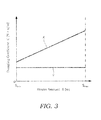
- the abscissa shows a stroke amount S [m], which is an amount by which the piston rod 22 advances into the cylinder 10, while the ordinate shows a damping coefficient C [N x s/m] of the magnetorheological fluid shock absorber 100.
- a straight line X represents the damping coefficient C of the magnetorheological fluid shock absorber 100
- a straight line Y represents the damping coefficient C in a case where the magnetorheological fluid shock absorber 100 is not provided with the magnet portion 30 such that a magnetic field is not applied to the magnetorheological fluid in the cylinder 10.
- the annular interval serving as the throttle between the piston 21 and the cylinder 10 remains constant at all times, even when the piston rod 22 advances into the cylinder 10. Further, since the magnet portion 30 is not provided, the magnetorheological fluid in the cylinder 10 is not affected by a magnetic field, and therefore the viscosity of the magnetorheological fluid in the cylinder 10 remains constant regardless of the stroke amount of the piston rod 22. Hence, as shown by the straight line Y, the damping coefficient C in this case takes a constant value at all times relative to variation in the stroke amount S.
- the damping coefficient C is at a minimum when the stroke amount is S min , i.e. when the piston rod 22 is furthest withdrawn from the cylinder 10. Even when the stroke amount is S min , however, the magnetic field generated by the magnet portion 30 affects the magnetorheological fluid in the cylinder 10 such that the ferromagnetic microparticles are aligned, and therefore the damping coefficient C is larger than that of the case in which the magnet portion 30 is not provided.
- the damping coefficient C increases proportionally, and when the stroke amount reaches S max , the damping coefficient C reaches a maximum.
- the reason for this is that the viscosity of the magnetorheological fluid in the annular interval between the piston 21 and the cylinder 10 gradually increases.
- a length of the annular interval between the piston 21 and the cylinder 10 that is directly affected by the magnetic field gradually increases.
- the damping coefficient C of the magnetorheological fluid shock absorber 100 can be increased proportionally relative to the stroke amount of the piston rod 22 in the advancement direction into the cylinder 10.
- the cylinder 10 and the piston 21 are formed from a non-magnetic material, and the magnet portion 30 that applies a magnetic field to the magnetorheological fluid in the cylinder 10 is attached to the cylinder 10.
- the cylinder 10 and the piston 21 do not form a magnetic path, and therefore the effect of the magnetic field on the magnetorheological fluid passing through the interval between the cylinder 10 and the piston 21 increases gradually as the piston 21 strokes toward the magnet portion 30.
- the damping coefficient can be varied continuously relative to the stroke amount of the piston 21.
- the magnet portion 30 includes the pair of permanent magnets 31 having an inner peripheral shape that aligns with the outer peripheral shape of the cylindrical cylinder 10 in which the magnetorheological fluid is sealed.
- the pair of permanent magnets 31 are disposed such that opposite magnetic poles oppose each other about the central axis of the cylinder 10. Hence, the magnetic field generated by the pair of permanent magnets 31 acts in a direction following an outer wall of the piston 21, and as a result, the magnetic field can be applied to the magnetorheological fluid efficiently.
- FIG. 4A is a sectional view of the cylinder 10 and the magnet portion 30 in a magnetorheological fluid shock absorber according to the second embodiment of this invention
- FIG. 4B is a view illustrating the permanent magnets 31 of the magnetorheological fluid shock absorber according to the second embodiment of this invention.
- the magnetorheological fluid shock absorber according to the second embodiment has an identical overall basic configuration to the magnetorheological fluid shock absorber 100 according to the first embodiment, shown in FIG. 1 .
- the magnetorheological fluid shock absorber according to the second embodiment differs from the magnetorheological fluid shock absorber 100 according to the first embodiment only in the configuration of the magnet portion 30.
- Each permanent magnet 31 is a C-shaped segment magnets.
- the pair of permanent magnets 31 are formed in an identical shape and disposed symmetrically about the central axis of the cylinder 10.
- the permanent magnets 31 are magnetized by groups of magnetic poles in the circumferential direction, as shown in FIG. 4B .
- one side portion 31c in the circumferential direction is magnetized to an N pole
- the other side portion 31c is magnetized to an S pole.
- one permanent magnet 31 and the other permanent magnet 31 are respectively disposed symmetrically about the central axis of the cylinder 10.
- the magnetic pole in one side portion 31c of one permanent magnet 31 is an N pole
- the magnetic pole in the same side portion 31c of the opposing permanent magnet 31 is also an N pole.
- the magnetic pole in the other side portion 31c of the first permanent magnet 31 is an S pole
- the magnetic pole in the same side portion 31c of the opposing permanent magnet 31 is also an S pole.
- the magnet portion 30 generates a magnetic field in the direction of an arrow shown in FIG. 4A .
- a magnetic field is generated in a direction following the outer edge of the cylinder 10.
- the magnetic field is applied evenly over the magnetorheological fluid existing in the interval between the piston 21 and the cylinder 10, and as a result, the viscosity of the magnetorheological fluid can be increased.
- the damping coefficient can be varied continuously relative to the stroke amount of the piston 2 1.
- the pair of permanent magnets 31 are disposed such that identical magnetic poles oppose each other. Therefore, a strongly repellent magnetic field is generated by the opposing magnetic poles in the vicinity of the side portions 31c. As a result, the magnetic field can be applied to the magnetorheological fluid even more effectively.
- Tokugan 2011-131258, with a filing date of June 13, 2011 in Japan, are hereby incorporated by reference.
Landscapes
- Engineering & Computer Science (AREA)
- General Engineering & Computer Science (AREA)
- Mechanical Engineering (AREA)
- Physics & Mathematics (AREA)
- Electromagnetism (AREA)
- Fluid-Damping Devices (AREA)
- Textile Engineering (AREA)
- Vibration Prevention Devices (AREA)
Abstract
Description
- This invention relates to a magnetorheological fluid shock absorber that uses a magnetorheological fluid having an apparent viscosity that is varied by an action of a magnetic field.
- A damping force of a shock absorber installed in a vehicle such as an automobile may be varied by applying a magnetic field to a flow passage through which a magnetorheological fluid passes in order to vary an apparent viscosity of the magnetorheological fluid.
-
JP2007-239982A - With the magnetorheological fluid shock absorber described in
JP2007-239982A - This invention has been designed in consideration of the problems described above, and an object thereof is to provide a magnetorheological fluid shock absorber in which a magnet is attached to a cylinder, and with which magnetism is applied efficiently so that a damping coefficient is varied continuously relative to a stroke amount of a piston.
- According to one aspect of this invention, a magnetorheological fluid shock absorber that uses a magnetorheological fluid having a viscosity that is varied by an action of a magnetic field is provided. The magnetorheological fluid shock absorber includes: a tubular cylinder formed from a non-magnetic material, in which the magnetorheological fluid is sealed; a piston formed from a non-magnetic material and disposed in the cylinder to be free to slide at an interval, through which the magnetorheological fluid can pass, relative to an inner periphery of the cylinder; a piston rod to which the piston is connected; and a magnet portion attached to the cylinder in order to apply a magnetic field to an interior of the cylinder. The magnet portion includes a pair of permanent magnets that are respectively formed in an arc shape having an inner peripheral shape that aligns with an outer periphery of the cylinder, magnetized in a circumferential direction, and disposed so as to face each other about a central axis of the cylinder.
- The details as well as other features and advantages of this invention are set forth in the remainder of the specification and are shown in the accompanying drawings.
-
-
FIG. 1 is a sectional view of a magnetorheological fluid shock absorber according to a first embodiment of this invention. -
FIG. 2A is a IIA-IIA sectional view ofFIG. 1 . -
FIG. 2B is a view illustrating a permanent magnet of the magnetorheological fluid shock absorber according to the first embodiment of this invention. -
FIG. 3 is a graph illustrating an action of the magnetorheological fluid shock absorber according to the first embodiment of this invention. -
FIG. 4A is a sectional view showing a piston, a cylinder, and a magnet portion of a magnetorheological fluid shock absorber according to a second embodiment of this invention. -
FIG. 4B is a view illustrating a permanent magnet of the magnetorheological fluid shock absorber according to the second embodiment of this invention. - Embodiments of this invention will be described below with reference to the figures.
- First, referring to
FIG. 1 , an overall configuration of a magnetorheological fluid shock absorber 100 according to a first embodiment of this invention will be described.FIG. 1 is a sectional view of the magnetorheological fluid shock absorber 100. - The magnetorheological fluid shock absorber 100 is a damper in which a damping coefficient relative to a force applied in an axial direction can be varied using a magnetorheological fluid that is varied in viscosity by an action of a magnetic field. The magnetorheological
fluid shock absorber 100 is formed such that the damping coefficient thereof varies proportionally in accordance with a stroke amount of apiston 21. - The magnetorheological fluid shock absorber 100 includes a
tubular cylinder 10 having a magnetorheological fluid sealed into an inner periphery thereof, thepiston 21, which is disposed in thecylinder 10 to be free to slide in an axial direction of thecylinder 10, apiston rod 22 to which thepiston 21 is connected, and amagnet portion 30 that is fixed to an outer periphery of thecylinder 10 in order to apply a magnetic field to an interior of thecylinder 10. - The magnetorheological fluid sealed in the
cylinder 10 is a fluid formed by dispersing ferromagnetic microparticles through a fluid such as oil, and has an apparent viscosity that is varied by an action of a magnetic field. The viscosity of the magnetorheological fluid varies in accordance with an intensity of the applied magnetic field, and reaches a minimum when no magnetic field effect is present. - The
cylinder 10 includes acylindrical portion 11 formed in a cylindrical shape having opening portions at either end, and ahead member 12 and abottom member 13 respectively attached to the opening portions at either end of thecylindrical portion 11. - The
cylindrical portion 11 includes ascrew portion 11a formed on an inner periphery in one opening portion, and ascrew portion 11b formed on an inner periphery in the other opening portion. - A
screw portion 12b that is screwed to thescrew portion 11a of thecylindrical portion 11 is formed on an outer periphery of thehead member 12. Aseal member 14a is provided between the inner periphery of thecylindrical portion 11 and the outer periphery of thehead member 12 so that the magnetorheological fluid is sealed within thecylinder 10. Ahole 12a for inserting thepiston rod 22 is formed in thehead member 12. - Similarly, a
screw portion 13b that is screwed to thescrew portion 11b of thecylindrical portion 11 is formed on an outer periphery of thebottom member 13. Aseal member 14b is provided between the inner periphery of thecylindrical portion 11 and the outer periphery of thebottom member 13 so that the magnetorheological fluid is sealed within thecylinder 10. Ahole 13a for inserting thepiston rod 22 is formed in thebottom member 13. - The
cylinder 10 is formed from a non-magnetic material. In so doing, thecylinder 10 can be prevented from forming a magnetic path, and therefore a magnetic field can be applied efficiently from themagnet portion 30 to the magnetorheological fluid sealed in thecylinder 10. - The
cylinder 10 includes an annular recessedportion 15 formed on the outer periphery of thecylindrical portion 11 to be thinner than other parts of thecylinder 10. Themagnet portion 10 is fitted around therecessed portion 15. - The
piston 21 is formed in a columnar shape having a smaller outer diameter than an inner diameter of thecylindrical portion 11 of thecylinder 10. In other words, thepiston 21 is formed at an annular interval, through which the magnetorheological fluid can pass, relative to the inner periphery of thecylindrical portion 11 of thecylinder 10. - When the
piston 21 slides through thecylinder 10 in the axial direction, the magnetorheological fluid passes through the interval between thepiston 21 and thecylinder 10. The annular interval between thepiston 21 and thecylinder 10 serves as a throttle by which the magnetorheological fluid shock absorber 100 generates a damping force. - The
piston 21 is formed from a non-magnetic material. In so doing, the magnetic field from themagnet portion 30 can be prevented from acting directly on thepiston 21, and an increase in friction occurring when thepiston 21 is pulled to one side can be prevented. - The
piston rod 22 is formed coaxially with thepiston 21, and penetrates a center of thepiston 21. Thepiston rod 22 is formed integrally with thepiston 21. Thepiston rod 22 may be formed separately from thepiston 21 and joined thereto by a screw or the like. - One
end portion 22a of thepiston rod 22 penetrates thehole 12a in thehead member 12 and extends to the outside of thecylinder 10 while being supported by thehead member 12 to be free to slide. Anotherend portion 22b of thepiston rod 22 penetrates thehole 13a in thebottom member 13 and is supported by thebottom member 13 to be free to slide. - By supporting the
piston rod 22 to be free to slide using thehead member 12 and thebottom member 13 in this manner, thepiston rod 22 can slide in the axial direction without deviating in a radial direction within thecylinder 10 even though the annular interval is formed between the outer periphery of thepiston 21 and the inner periphery of thecylinder 10. - Next, referring to
FIGS. 2A and2B , themagnet portion 30 will be described.FIG. 2A is a IIA-IIA sectional view ofFIG. 1 .FIG. 2B is a view illustrating apermanent magnet 31 of the magnetorheologicalfluid shock absorber 100 according to the first embodiment of this invention. - As shown in
FIG. 2A , themagnet portion 30 is formed with an annular cross-section. Themagnet portion 30 is fitted around the recessedportion 15 of thecylinder 10. The recessedportion 15 is formed to be thinner than the other parts of thecylinder 10. As a result, the magnetic field from themagnet portion 30 is not prevented from acting on the magnetorheological fluid sealed in thecylinder 10. - The
magnet portion 30 is constituted by a pair ofpermanent magnets 31, asupport member 33 supporting thepermanent magnets 31, and anannular ring member 32 fitted around thepermanent magnets 31 and thesupport member 33. - Each
permanent magnet 31 is a C-shaped segment magnet having an arc shape that is surrounded by an innerperipheral surface 31a constituted by a partial arc of a first circumference centering on an identical axis to an axial center of thecylinder 10, an outerperipheral surface 31b constituted by a partial arc of a second circumference that is concentric with the first circumference but has a larger diameter than the first circumference, and a pair ofside portions 31c linking the innerperipheral surface 31a to the outerperipheral surface 31b. The pair ofpermanent magnets 31 are formed in an identical shape and disposed symmetrically about the central axis of thecylinder 10. - As shown in
FIG. 2B , thepermanent magnets 31 are magnetized by groups of magnetic poles in a circumferential direction. In the example shown inFIG. 2B , thepermanent magnets 31 are magnetized to an N pole in oneside portion 31c in the circumferential direction, and magnetized to an S pole in anotherside portion 31c. In themagnet portion 30, the pair ofpermanent magnets 31 are disposed in rotational symmetry relative to the central axis of thecylinder 10. In other words, the magnetic poles of the pair ofpermanent magnets 31 respectively oppose opposite poles. - More specifically, the magnetic pole on the
side portion 31c of one of thepermanent magnets 31 is an N pole, and the magnetic pole on thesame side portion 31c of the opposingpermanent magnet 31 is an S pole. Further, the magnetic pole on theother side portion 31c of the firstpermanent magnet 31 is an S pole, and the magnetic pole on thesame side portion 31c of the opposingpermanent magnet 31 is an N pole. - An inner peripheral side of the
support member 33 is formed in a cylindrical shape that aligns with the periphery of the recessedportion 15 formed in an annular shape. Agroove portion 33a and agroove portion 33b for fixing thepermanent magnets 31 to a circumferential outer form are formed on an outer peripheral side of thesupport member 33. When thepermanent magnets 31 are fixed respectively to thegroove portion 33a and thegroove portion 33b, the outer periphery of thesupport member 33 forms an identical circle to the aforesaid second circumference. - The
support member 33 is formed from a non-magnetic material, similarly to thecylinder 10. In so doing, thesupport member 33 is prevented from forming a magnetic path, and therefore the magnetic field from themagnet portion 30 is applied to the magnetorheological fluid efficiently. - The
annular ring member 32 is fitted to the outer periphery of thesupport member 33. Thering member 32 is fitted tightly to the outer periphery of thesupport member 33 in a condition where thepermanent magnets 31 are fixed respectively to thegroove portion 33a and thegroove portion 33b. Thering member 32 is formed from a non-magnetic material. Thering member 32 is attached to prevent impurities from adhering to thepermanent magnet 31. Hence, thering member 32 is not limited to a tubular non-magnetic member, and may be applied by painting, coating, or the like. - The pair of
permanent magnets 31 are fixed by thesupport member 33 so as to be removed from each other. In other words, a central angle of the innerperipheral surface 31a and the outerperipheral surface 31b of thepermanent magnet 31 is set at less than 180°. Further, the outerperipheral surface 31b of thepermanent magnet 31 closely contacts an inner peripheral surface of thering member 32. - With this configuration, the
magnet portion 30 generates a magnetic field in a direction indicated by an arrow inFIG. 2A . More specifically, by disposing the pair ofpermanent magnets 31, a magnetic field is generated in a direction following an outer edge of thecylinder 10 by the mutually opposing magnetic poles, particularly in the vicinity of theside portions 31c. The magnetic field acts on the magnetorheological fluid existing in the interval between thepiston 21 and thecylinder 10, and as a result, the viscosity of the magnetorheological fluid can be increased. - The
magnet portion 30 is disposed to correspond to a position of thepiston 21 when thepiston rod 22 is furthest advanced into thecylinder 10. Hence, the viscosity of the magnetorheological fluid in thecylinder 10 differs according to the axial direction position. More specifically, the ferromagnetic microparticles gather in the vicinity of themagnet portion 30 due to an increase in the effect of the magnetic field, and therefore the viscosity of the magnetorheological fluid in thecylinder 10 increases gradually toward themagnet portion 30. Away from themagnet portion 30, on the other hand, the effect of the magnetic field decreases, leading to a reduction in the viscosity of the magnetorheological fluid in thecylinder 10. - Hence, when the
piston rod 22 strokes in an advancement direction into thecylinder 10, the effect of the magnetic field generated by themagnet portion 30 on the magnetorheological fluid passing through the interval between thepiston 21 and thecylinder 10 gradually increases. Therefore, the apparent viscosity of the magnetorheological fluid increases in accordance with the stroke of thepiston rod 22 in the advancement direction into thecylinder 10. Accordingly, the damping coefficient of the magnetorheologicalfluid shock absorber 100 increases as thepiston rod 22 advances into thecylinder 10, and as a result, the damping coefficient can be varied continuously in accordance with the stroke amount of thepiston 21. - Next, referring to
FIG. 3 , actions of the magnetorheologicalfluid shock absorber 100 will be described. - In
FIG. 3 , the abscissa shows a stroke amount S [m], which is an amount by which thepiston rod 22 advances into thecylinder 10, while the ordinate shows a damping coefficient C [N x s/m] of the magnetorheologicalfluid shock absorber 100. InFIG. 3 , a straight line X represents the damping coefficient C of the magnetorheologicalfluid shock absorber 100, while a straight line Y represents the damping coefficient C in a case where the magnetorheologicalfluid shock absorber 100 is not provided with themagnet portion 30 such that a magnetic field is not applied to the magnetorheological fluid in thecylinder 10. - When the
magnet portion 30 is not provided, the annular interval serving as the throttle between thepiston 21 and thecylinder 10 remains constant at all times, even when thepiston rod 22 advances into thecylinder 10. Further, since themagnet portion 30 is not provided, the magnetorheological fluid in thecylinder 10 is not affected by a magnetic field, and therefore the viscosity of the magnetorheological fluid in thecylinder 10 remains constant regardless of the stroke amount of thepiston rod 22. Hence, as shown by the straight line Y, the damping coefficient C in this case takes a constant value at all times relative to variation in the stroke amount S. - In the magnetorheological
fluid shock absorber 100, on the other hand, as shown by the straight line X, the damping coefficient C is at a minimum when the stroke amount is Smin, i.e. when thepiston rod 22 is furthest withdrawn from thecylinder 10. Even when the stroke amount is Smin, however, the magnetic field generated by themagnet portion 30 affects the magnetorheological fluid in thecylinder 10 such that the ferromagnetic microparticles are aligned, and therefore the damping coefficient C is larger than that of the case in which themagnet portion 30 is not provided. - As the
piston rod 22 gradually advances into thecylinder 10 from the stroke amount Smin, the damping coefficient C increases proportionally, and when the stroke amount reaches Smax, the damping coefficient C reaches a maximum. The reason for this is that the viscosity of the magnetorheological fluid in the annular interval between thepiston 21 and thecylinder 10 gradually increases. Moreover, as thepiston 21 advances to the inner peripheral side of themagnet portion 30 where the effect of the magnetic field is large, a length of the annular interval between thepiston 21 and thecylinder 10 that is directly affected by the magnetic field gradually increases. - By disposing the
magnet portion 30 in the position corresponding to the position of thepiston 21 when thepiston rod 22 is furthest advanced into thecylinder 10 in this manner, the damping coefficient C of the magnetorheologicalfluid shock absorber 100 can be increased proportionally relative to the stroke amount of thepiston rod 22 in the advancement direction into thecylinder 10. - With the first embodiment described above, following effects are obtained.
- The
cylinder 10 and thepiston 21 are formed from a non-magnetic material, and themagnet portion 30 that applies a magnetic field to the magnetorheological fluid in thecylinder 10 is attached to thecylinder 10. Hence, thecylinder 10 and thepiston 21 do not form a magnetic path, and therefore the effect of the magnetic field on the magnetorheological fluid passing through the interval between thecylinder 10 and thepiston 21 increases gradually as thepiston 21 strokes toward themagnet portion 30. As a result, the damping coefficient can be varied continuously relative to the stroke amount of thepiston 21. - Further, the
magnet portion 30 includes the pair ofpermanent magnets 31 having an inner peripheral shape that aligns with the outer peripheral shape of thecylindrical cylinder 10 in which the magnetorheological fluid is sealed. The pair ofpermanent magnets 31 are disposed such that opposite magnetic poles oppose each other about the central axis of thecylinder 10. Hence, the magnetic field generated by the pair ofpermanent magnets 31 acts in a direction following an outer wall of thepiston 21, and as a result, the magnetic field can be applied to the magnetorheological fluid efficiently. - Next, referring to
FIGS. 4A and4B , a second embodiment of this invention will be described. It should be noted that in the second embodiment, identical configurations to the first embodiment have been allocated identical reference symbols, and duplicate description thereof has been omitted where appropriate.FIG. 4A is a sectional view of thecylinder 10 and themagnet portion 30 in a magnetorheological fluid shock absorber according to the second embodiment of this invention, andFIG. 4B is a view illustrating thepermanent magnets 31 of the magnetorheological fluid shock absorber according to the second embodiment of this invention. - The magnetorheological fluid shock absorber according to the second embodiment has an identical overall basic configuration to the magnetorheological
fluid shock absorber 100 according to the first embodiment, shown inFIG. 1 . The magnetorheological fluid shock absorber according to the second embodiment differs from the magnetorheologicalfluid shock absorber 100 according to the first embodiment only in the configuration of themagnet portion 30. - The
magnet portion 30, similarly to the first embodiment shown inFIG. 2 , is constituted by the pair ofpermanent magnets 31, thesupport member 33 supporting thepermanent magnets 31, and theannular ring member 32 fitted around thepermanent magnets 31 and thesupport member 33. - Each
permanent magnet 31 is a C-shaped segment magnets. The pair ofpermanent magnets 31 are formed in an identical shape and disposed symmetrically about the central axis of thecylinder 10. - In the second embodiment, the
permanent magnets 31 are magnetized by groups of magnetic poles in the circumferential direction, as shown inFIG. 4B . In the example shown inFIG. 4B , oneside portion 31c in the circumferential direction is magnetized to an N pole, and theother side portion 31c is magnetized to an S pole. Further, onepermanent magnet 31 and the otherpermanent magnet 31 are respectively disposed symmetrically about the central axis of thecylinder 10. In other words, the magnetic pole in oneside portion 31c of onepermanent magnet 31 is an N pole, and the magnetic pole in thesame side portion 31c of the opposingpermanent magnet 31 is also an N pole. Further, the magnetic pole in theother side portion 31c of the firstpermanent magnet 31 is an S pole, and the magnetic pole in thesame side portion 31c of the opposingpermanent magnet 31 is also an S pole. - With this configuration, the
magnet portion 30 generates a magnetic field in the direction of an arrow shown inFIG. 4A . In other words, by combining the magnetic poles of the pair ofpermanent magnets 31, a magnetic field is generated in a direction following the outer edge of thecylinder 10. The magnetic field is applied evenly over the magnetorheological fluid existing in the interval between thepiston 21 and thecylinder 10, and as a result, the viscosity of the magnetorheological fluid can be increased. - In the vicinity of the
side portions 31c of thepermanent magnets 31 in particular, mutually repellent magnetic poles are disposed, and therefore a large magnetic field is generated in mutually repellent directions. As a result, the viscosity of the magnetorheological fluid can be increased. - Hence, in the second embodiment of this invention, similarly to the first embodiment, the damping coefficient can be varied continuously relative to the stroke amount of the piston 2 1.
- Further, in the second embodiment of this invention, the pair of
permanent magnets 31 are disposed such that identical magnetic poles oppose each other. Therefore, a strongly repellent magnetic field is generated by the opposing magnetic poles in the vicinity of theside portions 31c. As a result, the magnetic field can be applied to the magnetorheological fluid even more effectively. - Although the invention has been described above with reference to certain embodiments, the invention is not limited to the embodiments described above. Modifications and variations of the embodiments described above will occur to those skilled in the art, within the scope of the claims.
- The contents of
Tokugan 2011-131258, with a filing date of June 13, 2011 - The embodiments of this invention in which an exclusive property or privilege is claimed are defined as follows:
Claims (5)
- A magnetorheological fluid shock absorber that uses a magnetorheological fluid having a viscosity that is varied by an action of a magnetic field, comprising:a tubular cylinder formed from a non-magnetic material, in which the magnetorheological fluid is sealed;a piston formed from a non-magnetic material and disposed in the cylinder to be free to slide at an interval, through which the magnetorheological fluid can pass, relative to an inner periphery of the cylinder;a piston rod to which the piston is connected; anda magnet portion attached to the cylinder in order to apply a magnetic field to an interior of the cylinder,wherein the magnet portion comprises a pair of permanent magnets that are respectively formed in an arc shape having an inner peripheral shape that aligns with an outer periphery of the cylinder, magnetized in a circumferential direction, and disposed so as to face each other about a central axis of the cylinder.
- The magnetorheological fluid shock absorber as defined in Claim 1, wherein the magnet portion is disposed to correspond to a position of the piston when the piston rod is furthest advanced into the cylinder.
- The magnetorheological fluid shock absorber as defined in Claim 1, wherein the pair of permanent magnets are disposed to have opposite magnetic poles about the central axis of the cylinder.
- The magnetorheological fluid shock absorber as defined in Claim 1, wherein the pair of permanent magnets are disposed to have symmetrical magnetic poles about the central axis of the cylinder.
- The magnetorheological fluid shock absorber as defined in Claim 1, wherein the magnet portion comprises a ring-shaped ring member formed from a non-magnetic material and fitted around the permanent magnets.
Applications Claiming Priority (2)
| Application Number | Priority Date | Filing Date | Title |
|---|---|---|---|
| JP2011131258A JP5789422B2 (en) | 2011-06-13 | 2011-06-13 | Magnetorheological fluid shock absorber |
| PCT/JP2012/063712 WO2012172963A1 (en) | 2011-06-13 | 2012-05-29 | Magnetic viscous damper |
Publications (3)
| Publication Number | Publication Date |
|---|---|
| EP2719917A1 true EP2719917A1 (en) | 2014-04-16 |
| EP2719917A4 EP2719917A4 (en) | 2015-07-22 |
| EP2719917B1 EP2719917B1 (en) | 2018-07-18 |
Family
ID=47356956
Family Applications (1)
| Application Number | Title | Priority Date | Filing Date |
|---|---|---|---|
| EP12800951.1A Not-in-force EP2719917B1 (en) | 2011-06-13 | 2012-05-29 | Magnetorheological fluid shock absorber |
Country Status (6)
| Country | Link |
|---|---|
| US (1) | US20140110200A1 (en) |
| EP (1) | EP2719917B1 (en) |
| JP (1) | JP5789422B2 (en) |
| KR (1) | KR20140012173A (en) |
| CN (1) | CN103597241B (en) |
| WO (1) | WO2012172963A1 (en) |
Families Citing this family (6)
| Publication number | Priority date | Publication date | Assignee | Title |
|---|---|---|---|---|
| JP5821095B2 (en) * | 2011-06-13 | 2015-11-24 | Kyb株式会社 | Magnetorheological fluid shock absorber |
| KR101563962B1 (en) | 2014-05-30 | 2015-10-28 | 주식회사 만도 | Pressurized magnetorheological fluid dampers |
| KR102084639B1 (en) * | 2015-06-22 | 2020-03-04 | 알프스 알파인 가부시키가이샤 | Input device and control method of input device |
| CN108028116B (en) * | 2015-09-15 | 2020-01-21 | 本田技研工业株式会社 | Magnetoviscous fluid composition and vibration damping device using the same |
| CN114135619A (en) * | 2021-11-13 | 2022-03-04 | 安徽工程大学 | Damping type energy dissipation device repairing device based on magnetic control principle |
| CN114607727B (en) * | 2022-03-09 | 2023-04-07 | 浙江师范大学 | A kind of magneto-rheological fluid automobile bumper |
Family Cites Families (19)
| Publication number | Priority date | Publication date | Assignee | Title |
|---|---|---|---|---|
| US2622707A (en) * | 1950-02-28 | 1952-12-23 | Gen Electric | Liquid magnetic damper |
| JPS5610844A (en) * | 1979-07-02 | 1981-02-03 | Toyota Motor Corp | Feedback control system vibration absorbing suspension |
| JPS57161330A (en) * | 1981-03-27 | 1982-10-04 | Matsushita Electric Works Ltd | Oil dashpot |
| JPS60121948A (en) * | 1983-12-01 | 1985-06-29 | Nippon Denso Co Ltd | Permanent magnet fixing system of magnet rotor of electric rotary machine |
| US4945330A (en) * | 1988-03-28 | 1990-07-31 | Mitsubuishi Kasei | Actuator |
| DE3836897A1 (en) * | 1988-10-29 | 1990-05-03 | Stabilus Gmbh | VENTILABLE PROTECTIVE COVER FOR THE PISTON ROD OF A HYDROPNEUMATIC ADJUSTMENT |
| JPH0552235A (en) * | 1991-08-23 | 1993-03-02 | Toshiba Corp | Viscous damper |
| JPH0541357U (en) * | 1991-11-05 | 1993-06-01 | 株式会社荻原製作所 | Permanent magnet rotor and electric motor |
| US5791445A (en) * | 1997-05-26 | 1998-08-11 | Fichtel & Sachs Industries, Inc. | Piston rod-cylinder assembly with shrink-wrap corrosion protective sleeve |
| US6471018B1 (en) * | 1998-11-20 | 2002-10-29 | Board Of Regents Of The University And Community College System On Behalf Of The University Of Nevada-Reno, The University Of Reno | Magneto-rheological fluid device |
| US6390253B1 (en) * | 1999-10-05 | 2002-05-21 | Delphi Technologies, Inc. | Magneto-rheological damping apparatus |
| WO2004018893A2 (en) * | 2002-08-21 | 2004-03-04 | Delphi Technologies, Inc. | Damper dust tube having velocity sensor |
| US7422092B2 (en) * | 2003-07-07 | 2008-09-09 | Gregory Hitchcock | Controllable compressible fluid damper |
| JP2005291338A (en) * | 2004-03-31 | 2005-10-20 | Hitachi Ltd | damper |
| JP4291211B2 (en) * | 2004-05-21 | 2009-07-08 | 三菱電機株式会社 | Rotating electric machine rotor and rotating electric machine |
| DE102005031950B3 (en) * | 2005-07-08 | 2007-03-01 | Stabilus Gmbh | gas spring |
| JP4728861B2 (en) | 2006-02-09 | 2011-07-20 | 財団法人電力中央研究所 | Magnetorheological fluid damper |
| CN101379317B (en) * | 2006-02-09 | 2010-07-14 | 财团法人电力中央研究所 | Fluid damper |
| DE102009034298A1 (en) * | 2009-07-21 | 2011-01-27 | Dt Swiss Ag | Damper device for a two-wheeler |
-
2011
- 2011-06-13 JP JP2011131258A patent/JP5789422B2/en not_active Expired - Fee Related
-
2012
- 2012-05-29 KR KR1020137033320A patent/KR20140012173A/en not_active Ceased
- 2012-05-29 US US14/125,923 patent/US20140110200A1/en not_active Abandoned
- 2012-05-29 EP EP12800951.1A patent/EP2719917B1/en not_active Not-in-force
- 2012-05-29 WO PCT/JP2012/063712 patent/WO2012172963A1/en not_active Ceased
- 2012-05-29 CN CN201280026181.4A patent/CN103597241B/en not_active Expired - Fee Related
Also Published As
| Publication number | Publication date |
|---|---|
| CN103597241A (en) | 2014-02-19 |
| JP5789422B2 (en) | 2015-10-07 |
| EP2719917B1 (en) | 2018-07-18 |
| WO2012172963A1 (en) | 2012-12-20 |
| US20140110200A1 (en) | 2014-04-24 |
| KR20140012173A (en) | 2014-01-29 |
| JP2013002471A (en) | 2013-01-07 |
| CN103597241B (en) | 2016-03-09 |
| EP2719917A4 (en) | 2015-07-22 |
Similar Documents
| Publication | Publication Date | Title |
|---|---|---|
| EP2719917B1 (en) | Magnetorheological fluid shock absorber | |
| JP5828558B2 (en) | Magnetorheological fluid shock absorber | |
| US9004243B2 (en) | Magneto-rheological damping assembly | |
| US20150008081A1 (en) | Magnetorheological fluid shock absorber | |
| CN105378324B (en) | Hydraulic shock absorbers and cover components | |
| US9732818B2 (en) | Axial engagement-controlled variable damper systems and methods | |
| EP2719918A1 (en) | Magnetic viscous damper | |
| CN106015437A (en) | Order-variable electromagnetic rheological damper | |
| KR101675704B1 (en) | Magnetorheological fluid shock absorber | |
| CN206017548U (en) | A kind of coil external MR damper for extending effective damping gap length | |
| CN104989775A (en) | Damping-adjustable magnetorheological damper | |
| JP5539243B2 (en) | Magnetorheological fluid shock absorber | |
| CN102297232A (en) | Single-outstretch pole ring-type piston magneto-rheological damper | |
| CN105179567A (en) | Single-rod variable-cylinder-body active single-control variable-damping magnetorheological damper | |
| CN106133383A (en) | Magnetic viscous fluid buffer | |
| JP5679864B2 (en) | Magnetorheological fluid shock absorber | |
| JP2007303581A (en) | Magnetorheological fluid shock absorber | |
| JP2017172750A (en) | Strut mount fixing structure | |
| CN108644296A (en) | A kind of interior wound MR damper that polypody parallel connection promotes |
Legal Events
| Date | Code | Title | Description |
|---|---|---|---|
| PUAI | Public reference made under article 153(3) epc to a published international application that has entered the european phase |
Free format text: ORIGINAL CODE: 0009012 |
|
| 17P | Request for examination filed |
Effective date: 20140113 |
|
| AK | Designated contracting states |
Kind code of ref document: A1 Designated state(s): AL AT BE BG CH CY CZ DE DK EE ES FI FR GB GR HR HU IE IS IT LI LT LU LV MC MK MT NL NO PL PT RO RS SE SI SK SM TR |
|
| DAX | Request for extension of the european patent (deleted) | ||
| RA4 | Supplementary search report drawn up and despatched (corrected) |
Effective date: 20150409 |
|
| RIC1 | Information provided on ipc code assigned before grant |
Ipc: F16F 9/53 20060101AFI20150401BHEP |
|
| RA4 | Supplementary search report drawn up and despatched (corrected) |
Effective date: 20150409 |
|
| RAP1 | Party data changed (applicant data changed or rights of an application transferred) |
Owner name: KYB CORPORATION |
|
| STAA | Information on the status of an ep patent application or granted ep patent |
Free format text: STATUS: EXAMINATION IS IN PROGRESS |
|
| 17Q | First examination report despatched |
Effective date: 20170608 |
|
| GRAP | Despatch of communication of intention to grant a patent |
Free format text: ORIGINAL CODE: EPIDOSNIGR1 |
|
| STAA | Information on the status of an ep patent application or granted ep patent |
Free format text: STATUS: GRANT OF PATENT IS INTENDED |
|
| INTG | Intention to grant announced |
Effective date: 20180215 |
|
| GRAS | Grant fee paid |
Free format text: ORIGINAL CODE: EPIDOSNIGR3 |
|
| RIN1 | Information on inventor provided before grant (corrected) |
Inventor name: SAITO, KEIJI Inventor name: SHIMADA, MIHO |
|
| GRAA | (expected) grant |
Free format text: ORIGINAL CODE: 0009210 |
|
| STAA | Information on the status of an ep patent application or granted ep patent |
Free format text: STATUS: THE PATENT HAS BEEN GRANTED |
|
| AK | Designated contracting states |
Kind code of ref document: B1 Designated state(s): AL AT BE BG CH CY CZ DE DK EE ES FI FR GB GR HR HU IE IS IT LI LT LU LV MC MK MT NL NO PL PT RO RS SE SI SK SM TR |
|
| REG | Reference to a national code |
Ref country code: GB Ref legal event code: FG4D |
|
| REG | Reference to a national code |
Ref country code: CH Ref legal event code: EP |
|
| REG | Reference to a national code |
Ref country code: IE Ref legal event code: FG4D |
|
| REG | Reference to a national code |
Ref country code: AT Ref legal event code: REF Ref document number: 1019701 Country of ref document: AT Kind code of ref document: T Effective date: 20180815 |
|
| REG | Reference to a national code |
Ref country code: DE Ref legal event code: R096 Ref document number: 602012048670 Country of ref document: DE |
|
| REG | Reference to a national code |
Ref country code: NL Ref legal event code: MP Effective date: 20180718 |
|
| REG | Reference to a national code |
Ref country code: LT Ref legal event code: MG4D |
|
| REG | Reference to a national code |
Ref country code: AT Ref legal event code: MK05 Ref document number: 1019701 Country of ref document: AT Kind code of ref document: T Effective date: 20180718 |
|
| PG25 | Lapsed in a contracting state [announced via postgrant information from national office to epo] |
Ref country code: NL Free format text: LAPSE BECAUSE OF FAILURE TO SUBMIT A TRANSLATION OF THE DESCRIPTION OR TO PAY THE FEE WITHIN THE PRESCRIBED TIME-LIMIT Effective date: 20180718 |
|
| PG25 | Lapsed in a contracting state [announced via postgrant information from national office to epo] |
Ref country code: NO Free format text: LAPSE BECAUSE OF FAILURE TO SUBMIT A TRANSLATION OF THE DESCRIPTION OR TO PAY THE FEE WITHIN THE PRESCRIBED TIME-LIMIT Effective date: 20181018 Ref country code: GR Free format text: LAPSE BECAUSE OF FAILURE TO SUBMIT A TRANSLATION OF THE DESCRIPTION OR TO PAY THE FEE WITHIN THE PRESCRIBED TIME-LIMIT Effective date: 20181019 Ref country code: PL Free format text: LAPSE BECAUSE OF FAILURE TO SUBMIT A TRANSLATION OF THE DESCRIPTION OR TO PAY THE FEE WITHIN THE PRESCRIBED TIME-LIMIT Effective date: 20180718 Ref country code: SE Free format text: LAPSE BECAUSE OF FAILURE TO SUBMIT A TRANSLATION OF THE DESCRIPTION OR TO PAY THE FEE WITHIN THE PRESCRIBED TIME-LIMIT Effective date: 20180718 Ref country code: FI Free format text: LAPSE BECAUSE OF FAILURE TO SUBMIT A TRANSLATION OF THE DESCRIPTION OR TO PAY THE FEE WITHIN THE PRESCRIBED TIME-LIMIT Effective date: 20180718 Ref country code: LT Free format text: LAPSE BECAUSE OF FAILURE TO SUBMIT A TRANSLATION OF THE DESCRIPTION OR TO PAY THE FEE WITHIN THE PRESCRIBED TIME-LIMIT Effective date: 20180718 Ref country code: RS Free format text: LAPSE BECAUSE OF FAILURE TO SUBMIT A TRANSLATION OF THE DESCRIPTION OR TO PAY THE FEE WITHIN THE PRESCRIBED TIME-LIMIT Effective date: 20180718 Ref country code: AT Free format text: LAPSE BECAUSE OF FAILURE TO SUBMIT A TRANSLATION OF THE DESCRIPTION OR TO PAY THE FEE WITHIN THE PRESCRIBED TIME-LIMIT Effective date: 20180718 Ref country code: BG Free format text: LAPSE BECAUSE OF FAILURE TO SUBMIT A TRANSLATION OF THE DESCRIPTION OR TO PAY THE FEE WITHIN THE PRESCRIBED TIME-LIMIT Effective date: 20181018 Ref country code: IS Free format text: LAPSE BECAUSE OF FAILURE TO SUBMIT A TRANSLATION OF THE DESCRIPTION OR TO PAY THE FEE WITHIN THE PRESCRIBED TIME-LIMIT Effective date: 20181118 |
|
| PG25 | Lapsed in a contracting state [announced via postgrant information from national office to epo] |
Ref country code: AL Free format text: LAPSE BECAUSE OF FAILURE TO SUBMIT A TRANSLATION OF THE DESCRIPTION OR TO PAY THE FEE WITHIN THE PRESCRIBED TIME-LIMIT Effective date: 20180718 Ref country code: LV Free format text: LAPSE BECAUSE OF FAILURE TO SUBMIT A TRANSLATION OF THE DESCRIPTION OR TO PAY THE FEE WITHIN THE PRESCRIBED TIME-LIMIT Effective date: 20180718 Ref country code: HR Free format text: LAPSE BECAUSE OF FAILURE TO SUBMIT A TRANSLATION OF THE DESCRIPTION OR TO PAY THE FEE WITHIN THE PRESCRIBED TIME-LIMIT Effective date: 20180718 |
|
| REG | Reference to a national code |
Ref country code: DE Ref legal event code: R097 Ref document number: 602012048670 Country of ref document: DE |
|
| PG25 | Lapsed in a contracting state [announced via postgrant information from national office to epo] |
Ref country code: EE Free format text: LAPSE BECAUSE OF FAILURE TO SUBMIT A TRANSLATION OF THE DESCRIPTION OR TO PAY THE FEE WITHIN THE PRESCRIBED TIME-LIMIT Effective date: 20180718 Ref country code: RO Free format text: LAPSE BECAUSE OF FAILURE TO SUBMIT A TRANSLATION OF THE DESCRIPTION OR TO PAY THE FEE WITHIN THE PRESCRIBED TIME-LIMIT Effective date: 20180718 Ref country code: IT Free format text: LAPSE BECAUSE OF FAILURE TO SUBMIT A TRANSLATION OF THE DESCRIPTION OR TO PAY THE FEE WITHIN THE PRESCRIBED TIME-LIMIT Effective date: 20180718 Ref country code: CZ Free format text: LAPSE BECAUSE OF FAILURE TO SUBMIT A TRANSLATION OF THE DESCRIPTION OR TO PAY THE FEE WITHIN THE PRESCRIBED TIME-LIMIT Effective date: 20180718 Ref country code: ES Free format text: LAPSE BECAUSE OF FAILURE TO SUBMIT A TRANSLATION OF THE DESCRIPTION OR TO PAY THE FEE WITHIN THE PRESCRIBED TIME-LIMIT Effective date: 20180718 |
|
| PLBE | No opposition filed within time limit |
Free format text: ORIGINAL CODE: 0009261 |
|
| STAA | Information on the status of an ep patent application or granted ep patent |
Free format text: STATUS: NO OPPOSITION FILED WITHIN TIME LIMIT |
|
| PG25 | Lapsed in a contracting state [announced via postgrant information from national office to epo] |
Ref country code: SK Free format text: LAPSE BECAUSE OF FAILURE TO SUBMIT A TRANSLATION OF THE DESCRIPTION OR TO PAY THE FEE WITHIN THE PRESCRIBED TIME-LIMIT Effective date: 20180718 Ref country code: DK Free format text: LAPSE BECAUSE OF FAILURE TO SUBMIT A TRANSLATION OF THE DESCRIPTION OR TO PAY THE FEE WITHIN THE PRESCRIBED TIME-LIMIT Effective date: 20180718 Ref country code: SM Free format text: LAPSE BECAUSE OF FAILURE TO SUBMIT A TRANSLATION OF THE DESCRIPTION OR TO PAY THE FEE WITHIN THE PRESCRIBED TIME-LIMIT Effective date: 20180718 |
|
| 26N | No opposition filed |
Effective date: 20190423 |
|
| PG25 | Lapsed in a contracting state [announced via postgrant information from national office to epo] |
Ref country code: SI Free format text: LAPSE BECAUSE OF FAILURE TO SUBMIT A TRANSLATION OF THE DESCRIPTION OR TO PAY THE FEE WITHIN THE PRESCRIBED TIME-LIMIT Effective date: 20180718 |
|
| REG | Reference to a national code |
Ref country code: DE Ref legal event code: R119 Ref document number: 602012048670 Country of ref document: DE |
|
| REG | Reference to a national code |
Ref country code: CH Ref legal event code: PL |
|
| GBPC | Gb: european patent ceased through non-payment of renewal fee |
Effective date: 20190529 |
|
| PG25 | Lapsed in a contracting state [announced via postgrant information from national office to epo] |
Ref country code: CH Free format text: LAPSE BECAUSE OF NON-PAYMENT OF DUE FEES Effective date: 20190531 Ref country code: LI Free format text: LAPSE BECAUSE OF NON-PAYMENT OF DUE FEES Effective date: 20190531 Ref country code: MC Free format text: LAPSE BECAUSE OF FAILURE TO SUBMIT A TRANSLATION OF THE DESCRIPTION OR TO PAY THE FEE WITHIN THE PRESCRIBED TIME-LIMIT Effective date: 20180718 |
|
| REG | Reference to a national code |
Ref country code: BE Ref legal event code: MM Effective date: 20190531 |
|
| PG25 | Lapsed in a contracting state [announced via postgrant information from national office to epo] |
Ref country code: LU Free format text: LAPSE BECAUSE OF NON-PAYMENT OF DUE FEES Effective date: 20190529 |
|
| PG25 | Lapsed in a contracting state [announced via postgrant information from national office to epo] |
Ref country code: TR Free format text: LAPSE BECAUSE OF FAILURE TO SUBMIT A TRANSLATION OF THE DESCRIPTION OR TO PAY THE FEE WITHIN THE PRESCRIBED TIME-LIMIT Effective date: 20180718 |
|
| PG25 | Lapsed in a contracting state [announced via postgrant information from national office to epo] |
Ref country code: DE Free format text: LAPSE BECAUSE OF NON-PAYMENT OF DUE FEES Effective date: 20191203 Ref country code: GB Free format text: LAPSE BECAUSE OF NON-PAYMENT OF DUE FEES Effective date: 20190529 Ref country code: IE Free format text: LAPSE BECAUSE OF NON-PAYMENT OF DUE FEES Effective date: 20190529 |
|
| PG25 | Lapsed in a contracting state [announced via postgrant information from national office to epo] |
Ref country code: BE Free format text: LAPSE BECAUSE OF NON-PAYMENT OF DUE FEES Effective date: 20190531 |
|
| PG25 | Lapsed in a contracting state [announced via postgrant information from national office to epo] |
Ref country code: FR Free format text: LAPSE BECAUSE OF NON-PAYMENT OF DUE FEES Effective date: 20190531 Ref country code: PT Free format text: LAPSE BECAUSE OF FAILURE TO SUBMIT A TRANSLATION OF THE DESCRIPTION OR TO PAY THE FEE WITHIN THE PRESCRIBED TIME-LIMIT Effective date: 20181118 |
|
| PG25 | Lapsed in a contracting state [announced via postgrant information from national office to epo] |
Ref country code: CY Free format text: LAPSE BECAUSE OF FAILURE TO SUBMIT A TRANSLATION OF THE DESCRIPTION OR TO PAY THE FEE WITHIN THE PRESCRIBED TIME-LIMIT Effective date: 20180718 |
|
| PG25 | Lapsed in a contracting state [announced via postgrant information from national office to epo] |
Ref country code: MT Free format text: LAPSE BECAUSE OF FAILURE TO SUBMIT A TRANSLATION OF THE DESCRIPTION OR TO PAY THE FEE WITHIN THE PRESCRIBED TIME-LIMIT Effective date: 20180718 Ref country code: HU Free format text: LAPSE BECAUSE OF FAILURE TO SUBMIT A TRANSLATION OF THE DESCRIPTION OR TO PAY THE FEE WITHIN THE PRESCRIBED TIME-LIMIT; INVALID AB INITIO Effective date: 20120529 |
|
| PG25 | Lapsed in a contracting state [announced via postgrant information from national office to epo] |
Ref country code: MK Free format text: LAPSE BECAUSE OF FAILURE TO SUBMIT A TRANSLATION OF THE DESCRIPTION OR TO PAY THE FEE WITHIN THE PRESCRIBED TIME-LIMIT Effective date: 20180718 |