EP2719537A2 - Image recording apparatus - Google Patents
Image recording apparatus Download PDFInfo
- Publication number
- EP2719537A2 EP2719537A2 EP13185165.1A EP13185165A EP2719537A2 EP 2719537 A2 EP2719537 A2 EP 2719537A2 EP 13185165 A EP13185165 A EP 13185165A EP 2719537 A2 EP2719537 A2 EP 2719537A2
- Authority
- EP
- European Patent Office
- Prior art keywords
- path
- ink
- liquid
- flow resistance
- resistance
- Prior art date
- Legal status (The legal status is an assumption and is not a legal conclusion. Google has not performed a legal analysis and makes no representation as to the accuracy of the status listed.)
- Withdrawn
Links
- 239000007788 liquid Substances 0.000 claims abstract description 47
- 239000000976 ink Substances 0.000 description 215
- 239000003086 colorant Substances 0.000 description 8
- 230000008859 change Effects 0.000 description 7
- 238000004891 communication Methods 0.000 description 7
- 230000008901 benefit Effects 0.000 description 4
- 239000004615 ingredient Substances 0.000 description 3
- 230000001133 acceleration Effects 0.000 description 2
- 238000001514 detection method Methods 0.000 description 2
- 230000000694 effects Effects 0.000 description 2
- 238000003780 insertion Methods 0.000 description 2
- 230000037431 insertion Effects 0.000 description 2
- 230000007246 mechanism Effects 0.000 description 2
- 230000004044 response Effects 0.000 description 2
- 206010047571 Visual impairment Diseases 0.000 description 1
- 239000012530 fluid Substances 0.000 description 1
- 239000006260 foam Substances 0.000 description 1
- 230000006872 improvement Effects 0.000 description 1
- 238000007689 inspection Methods 0.000 description 1
- 239000002184 metal Substances 0.000 description 1
- 238000012986 modification Methods 0.000 description 1
- 230000004048 modification Effects 0.000 description 1
- 239000004745 nonwoven fabric Substances 0.000 description 1
- 239000011347 resin Substances 0.000 description 1
- 229920005989 resin Polymers 0.000 description 1
- 238000005549 size reduction Methods 0.000 description 1
- 238000011144 upstream manufacturing Methods 0.000 description 1
Images




Classifications
-
- B—PERFORMING OPERATIONS; TRANSPORTING
- B41—PRINTING; LINING MACHINES; TYPEWRITERS; STAMPS
- B41J—TYPEWRITERS; SELECTIVE PRINTING MECHANISMS, i.e. MECHANISMS PRINTING OTHERWISE THAN FROM A FORME; CORRECTION OF TYPOGRAPHICAL ERRORS
- B41J2/00—Typewriters or selective printing mechanisms characterised by the printing or marking process for which they are designed
- B41J2/005—Typewriters or selective printing mechanisms characterised by the printing or marking process for which they are designed characterised by bringing liquid or particles selectively into contact with a printing material
- B41J2/01—Ink jet
- B41J2/17—Ink jet characterised by ink handling
- B41J2/175—Ink supply systems ; Circuit parts therefor
- B41J2/17503—Ink cartridges
- B41J2/17556—Means for regulating the pressure in the cartridge
-
- B—PERFORMING OPERATIONS; TRANSPORTING
- B41—PRINTING; LINING MACHINES; TYPEWRITERS; STAMPS
- B41J—TYPEWRITERS; SELECTIVE PRINTING MECHANISMS, i.e. MECHANISMS PRINTING OTHERWISE THAN FROM A FORME; CORRECTION OF TYPOGRAPHICAL ERRORS
- B41J2/00—Typewriters or selective printing mechanisms characterised by the printing or marking process for which they are designed
- B41J2/005—Typewriters or selective printing mechanisms characterised by the printing or marking process for which they are designed characterised by bringing liquid or particles selectively into contact with a printing material
- B41J2/01—Ink jet
- B41J2/17—Ink jet characterised by ink handling
- B41J2/175—Ink supply systems ; Circuit parts therefor
- B41J2/17503—Ink cartridges
-
- B—PERFORMING OPERATIONS; TRANSPORTING
- B41—PRINTING; LINING MACHINES; TYPEWRITERS; STAMPS
- B41J—TYPEWRITERS; SELECTIVE PRINTING MECHANISMS, i.e. MECHANISMS PRINTING OTHERWISE THAN FROM A FORME; CORRECTION OF TYPOGRAPHICAL ERRORS
- B41J2/00—Typewriters or selective printing mechanisms characterised by the printing or marking process for which they are designed
- B41J2/005—Typewriters or selective printing mechanisms characterised by the printing or marking process for which they are designed characterised by bringing liquid or particles selectively into contact with a printing material
- B41J2/01—Ink jet
- B41J2/17—Ink jet characterised by ink handling
- B41J2/175—Ink supply systems ; Circuit parts therefor
- B41J2/17503—Ink cartridges
- B41J2/1752—Mounting within the printer
-
- B—PERFORMING OPERATIONS; TRANSPORTING
- B41—PRINTING; LINING MACHINES; TYPEWRITERS; STAMPS
- B41J—TYPEWRITERS; SELECTIVE PRINTING MECHANISMS, i.e. MECHANISMS PRINTING OTHERWISE THAN FROM A FORME; CORRECTION OF TYPOGRAPHICAL ERRORS
- B41J2/00—Typewriters or selective printing mechanisms characterised by the printing or marking process for which they are designed
- B41J2/005—Typewriters or selective printing mechanisms characterised by the printing or marking process for which they are designed characterised by bringing liquid or particles selectively into contact with a printing material
- B41J2/01—Ink jet
- B41J2/17—Ink jet characterised by ink handling
- B41J2/175—Ink supply systems ; Circuit parts therefor
- B41J2/17503—Ink cartridges
- B41J2/17553—Outer structure
-
- B—PERFORMING OPERATIONS; TRANSPORTING
- B41—PRINTING; LINING MACHINES; TYPEWRITERS; STAMPS
- B41J—TYPEWRITERS; SELECTIVE PRINTING MECHANISMS, i.e. MECHANISMS PRINTING OTHERWISE THAN FROM A FORME; CORRECTION OF TYPOGRAPHICAL ERRORS
- B41J2/00—Typewriters or selective printing mechanisms characterised by the printing or marking process for which they are designed
- B41J2/005—Typewriters or selective printing mechanisms characterised by the printing or marking process for which they are designed characterised by bringing liquid or particles selectively into contact with a printing material
- B41J2/01—Ink jet
- B41J2/17—Ink jet characterised by ink handling
- B41J2/175—Ink supply systems ; Circuit parts therefor
- B41J2/17566—Ink level or ink residue control
-
- B—PERFORMING OPERATIONS; TRANSPORTING
- B41—PRINTING; LINING MACHINES; TYPEWRITERS; STAMPS
- B41J—TYPEWRITERS; SELECTIVE PRINTING MECHANISMS, i.e. MECHANISMS PRINTING OTHERWISE THAN FROM A FORME; CORRECTION OF TYPOGRAPHICAL ERRORS
- B41J29/00—Details of, or accessories for, typewriters or selective printing mechanisms not otherwise provided for
- B41J29/02—Framework
Definitions
- the present invention relates to an image recording apparatus, in which liquid is supplied from a liquid cartridge to a recording head mounted to a carriage via a tube.
- an ink-jet image recording apparatus which records an image on a recording medium such as a sheet of paper by ejecting ink onto the recording medium based on an input signal. More specifically, the ink-jet image recording apparatus has a recording head and the recording head ejects ink from its nozzles onto a recording medium, such that an image is formed on the recording medium.
- One type of the known recording head is mounted to a carriage and reciprocates together with the carriage in a predetermined direction relative to the recording medium.
- Driving force is transmitted to the carriage from a drive source such as a motor, and upon receiving the driving force the carriage reciprocates in the predetermined direction guided by a guide shaft or a guide rail. While the carriage is reciprocating, the recording head selectively ejects ink droplets onto the recording medium, and the ink droplets' landing on the recording medium forms an image on the recording medium.
- a flexible tube is provided between the ink cartridge and the recording head, as described in Patent Application Publication No. JP 2007-144905 . Because the tube is flexible, the tube flexes and stretches, following the reciprocal movement of the carriage. When the carriage is in a position closest to the ink cartridge, the tube is flexed, such that the tube extends, making a U-turn. When the cartridge is in a position farthest from the ink cartridge, the tube stretches, such that the tube extends, curving gently.
- a path-defining member is mounted to the carriage, and the path-defining member has a path formed therein.
- the path is connected to the tube and the recording head.
- the path-defining member also has a damper chamber at the path.
- at least a portion of the damper chamber is defined by a flexible film.
- the film deforms, such that the volume of the damper chamber changes, and the dynamic pressure is dampened by the deformation of the film.
- the acceleration added to the ink in the tube becomes larger, and therefore the dynamic pressure in the ink becomes larger.
- the area of the film of the damper chamber may be made larger, such that the volume change caused by the deformation of the film becomes bigger. Nevertheless, if the area of the film of the damper chamber is made larger, the damper chamber itself may become larger, and the recording head and the carriage also may become larger, which runs counter to a size-reduction trend.
- the inner diameter of the tube may be made smaller or the length of the tube may be made longer, such that the tube has an increased flow resistance.
- the increased flow resistance suppresses the dynamic pressure.
- the inner diameter of the tube is made smaller or the length of the tube is made longer to increase the flow resistance of the tube, it becomes difficult for the tube to flex to follow the movement of the carriage or the tube occupies more space, which is disadvantageous.
- the flow resistance of the tube needs to be set larger to suppress dynamic pressure. That is, the length of the tube needs to be made longer or the inner diameter of the tube needs to be made smaller.
- the flow resistance of tube is too high, the supply of ink from the tube to the recording head may not catch up with the consumption of ink at the recording head.
- the length of the tube needs to be made shorter or the inner diameter of the tube needs to be made larger.
- the length or inner diameter of the tube may be different from one tube to another.
- the lengths of the tubes are different from each other, it may be difficult to bind and arrange the tubes together for the tubes to follow the movement of the carriage.
- the flexibilities of the tubes are different from each other, and therefore it may be difficult to bind and arrange the tubes together for the tubes to follow the movement of the carriage.
- inks may flow though the same tube.
- a test ink for inspection at a factory and an ink for a user to actually use at a user's site may be different from each other, but may flow through the same tube.
- ink may be improved by the manufacturer, and the ingredients of the ink may be changed for the improvement. That is, the viscosity of the ink may change during the life time of the image recording apparatus, but flows through the same tube.
- it is difficult to optimize the flow resistance for different kinds of inks by adjusting the length or the inner diameter of the same tube through which the different kinds of inks flow. It is desired to optimize the flow resistance even if the viscosity of ink changes because of the change in the ingredients of the ink.
- a technical advantage of the present invention is that a flow resistance can be optimized according to the viscosity of a liquid stored in a liquid cartridge.
- an image recording apparatus according to claim 1 is provided.
- the flow resistance of the resistance portion, the flow resistance of the first path, and the flow resistance of the third path described in claim 1 are flow resistances when the same liquid flows through the resistance portion, the first path, and the third path, respectively.
- the flow resistance of the resistance portion is greater than the flow resistance of the first path, and the flow resistance of the resistance portion is greater than the flow resistance of the third path, the flow resistance of the resistance portion accounts for a large amount of the flow resistance of a path extending from the liquid cartridge to the path-defining member.
- the flow resistance of the resistance portion which is the largest of the compared three resistances, the flow resistance of the path extending from the liquid cartridge to the path-defining member can be optimized according to the viscosity of the liquid.
- Fig. 1 is a perspective view of a multi-function apparatus according to an embodiment.
- Fig. 2 is a vertical, cross-sectional view of the multi-function apparatus.
- Fig. 3 is a plan view of an inner structure of a printer portion of the multi-function apparatus.
- Fig. 4 is a plan view of the inner structure of the printer portion, in which a cover of a carriage is removed.
- Fig. 5 is a perspective view of a carriage main body to which a tube holding member is attached.
- Fig. 6 is an exploded, perspective view of a carriage, in which the carriage main body, the tube holding member, and a joint are illustrated.
- Fig. 7 is a perspective view of a path-defining member.
- Fig. 8 is a perspective view of a cartridge mounting portion on an opening side.
- Fig. 9 is a perspective view of the cartridge mounting portion on a resin-molded member side.
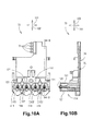
- Fig . 10A is an elevation view of the resin-molded member.
- Fig. 10B is a cross-sectional view of the resin-molded member, taken along line B-B in Fig . 10A .
- Fig. 11 is a perspective view of an ink cartridge.
- Fig. 12 is a schematic, cross-sectional view of the cartridge mounting portion and an image recording unit, etc., illustrating a path from the ink cartridge to a recording head.
- Fig. 13 is a schematic, cross-sectional view of the cartridge mounting portion and the image recording unit, etc., illustrating a path from the ink cartridge to the recording head, according to a modified embodiment.
- a multi-function apparatus 10 comprises an image recording apparatus, e.g. , a printer portion 11, and a scanner portion 11.
- the multi-function apparatus 10 functions as a printer, a scanner, a copier, and a facsimile machine.
- the printer portion 11 is positioned on the lower side of the multi-function apparatus 10, and the scanner portion 12 is positioned on the upper side of the multi-function apparatus 10.
- the printer portion 11 is configured to be connected to an external information device and is configured to record an image and texts based on print data including image data and text data transmitted from the external information device.
- the scanner portion 12 comprises a so-called flat-bed scanner.
- the multi-function apparatus 10 has substantially a rectangular parallelepiped shape with its dimension in a height direction 102 being less than its dimension in a width direction 101 and its dimension in a depth direction 103.
- the multi-function apparatus 10 has a user-interface side i.e. , a side facing a user when the user uses the multi-function apparatus 10, and a back side opposite the user-interface side in the depth direction 103.
- the printer portion 11 has an opening 13 formed therein on the user-interface side.
- the printer portion 11 comprise a paper feed tray 20 and a paper discharge tray 21, and the paper feed tray 20 and the paper discharge tray 21 are exposed to the outside of the printer portion 11 via opening 13. Sheets of paper as a recording medium stacked in the paper feed tray 20 are fed one by one for printing, and are discharged onto the discharge tray 21 after images are printed thereon.
- the multi-function apparatus 10 comprises an operation panel 14 at its upper portion on the user-interface side. Input operations are performed at the operation panel 14 for having the printer portion 11 and the scanner portion 12 work.
- the operation panel 14 comprises a plurality of buttons for the input operations and a display for indicating the status of the multi-function apparatus 10 and some error messages.
- the multi-function apparatus 10 When the multi-function apparatus 10 is connected to the external information device, the multi-function apparatus 10 also works based on inputs transmitted from the external information device via a communication software such as a print driver and a scanner driver.
- the paper feed tray 20 is positioned at the bottom most portion of the multi-function apparatus 10.
- the paper discharge tray 21 is positioned above the paper feed tray 20.
- the printer portion 11 comprises an image recording unit 24.
- the printer portion 11 has a paper conveying path 23 formed therein.
- a sheet of paper is fed from the paper feed tray 20 toward the back side of the multi-function apparatus 10 in the depth direction 103 , and then turns upward, making a U-turn toward the user-interface side in the depth direction 103. Subsequently, the sheet of paper is conveyed to the image recording unit 24, which records an image on the sheet of paper, and then discharged to the paper discharge tray 21
- the paper feed tray 20 has a container shape with its upper side opened, having an inner space formed therein. The sheets of paper are stacked in the inner space of the paper feed tray 20.
- the paper discharge tray 21 comprises an upper surface onto which the sheets of paper are discharged.
- the paper discharge tray 21 partly overlaps the paper feed tray 20 in the height direction 102, but is shifted from the paper feed tray 20 in the depth direction 103 toward the user-interface side. Therefore, the paper discharge tray 21 is not positioned directly above the paper feed tray 20 at a position closer to the back side of the multi-function apparatus 10.
- the printer portion 11 comprises a paper feed roller 25 directly above the paper feed tray 20 at a position closer to the back side of the multi-function apparatus 10.
- the paper feed roller 25 is configured to feed the sheets of paper stacked on the paper feed tray 20 one by one to the paper conveying path 23.
- the paper feed roller 25 is configured to rotate when receiving driving force from a motor (not shown).
- the printer portion 11 comprises a paper feed arm 26, and the paper feed arm 26 is pivotally supported at its one end.
- the paper feed roller 25 is rotatably supported at the free end of the paper feed arm 26. When the paper feed arm 26 pivots, the paper feed roller 25 moves toward and away from the paper feed tray 20.
- the paper feed arm 26 is urged downward by a spring (not shown) or by its own weight, and the paper feed roller 25 contacts the upper most one of the sheets of paper stacked in the paper feed tray 20.
- the position of the paper feed arm 26 and the paper feed roller 25 depends on how many sheets of paper are stacked in the paper feed tray 20.
- the paper conveying path 23 extends from the paper feed tray 20 at a position closer to the back side of the multi-function apparatus 10, goes upward, turning toward the user-interface side, and then extends from the back side toward the user-interface side of the multi-function apparatus 10 up to the paper discharge tray 21 via the image recording unit 24.
- the paper conveying path 23 is formed between outside guide surfaces and inside guide surfaces at positions other than where the image recording unit 24 is provided.
- the printer portion 11 comprises an outside guide member 18 and an inside guide member 19, and the paper conveying path 23 is formed between the outside guide member 18 and the inside guide member 19 at a position where the paper conveying path 23 curves on the back side of the multi-function apparatus 10.
- the image recording unit 24 comprises a carriage 38, a recording head 39 mounted to the carriage 38, and a platen 42 facing the recording head 39 with a predetermined gap formed therebetween in the height direction 102.
- the printer portion 10 comprises a conveying roller 60 and a pinch roller on the upstream side of the image recording unit 24 along the paper conveying path 23.
- the pinch roller is hidden by another part of the printer portion 10.
- the pinch roller is positioned below the conveying roller 60, and contacts and is urged toward the conveying roller 60.
- the conveying roller 60 is configured to rotate, driven by a motor (not shown). While pinching the sheet of paper therebetween, the conveying roller 60 and the pinch roller are configured to convey the sheet of paper onto the platen 42.
- the printer portion 10 comprises a discharge roller 62 and a spur on the downstream side of the image recording unit 24 along the paper conveying path 23.
- the spur is hidden by another part of the printer portion 10.
- the spur is positioned above the discharge roller 62, and contacts and is urged toward the discharge roller 62.
- the discharge roller 62 is configured to rotate, driven by a motor (not shown). While pinching the sheet of paper therebetween, the discharge roller 62 and the spur are configured to convey the sheet of paper onto the paper discharge tray 21.
- the printer portion 11 comprises four ink tubes 41, and each ink tube 41 has a path formed therein as an example of the third path.
- the printer portion 11 also comprises a cartridge mounting portion 110 positioned apart and away from the carriage 38 and four liquid cartridges, e.g. , four ink cartridges 32 configured to be mounted to the cartridge mounting portion 110.
- the recording head 39 mounted to the carriage 38 is configured to be supplied with ink via the path of the ink tubes 41 from the ink cartridges 32 respectively. More specifically, the ink cartridges 32 store cyan, magenta, yellow, and black inks respectively, and those inks are supplied to the recording head 39 via the ink tubes 41 respectively.
- the ink cartridges 32 and the cartridge mounting portion 110 are schematically illustrated in alternate long and short dash lines. While the carriage 38 is reciprocating, the recording head 39 selectively ejects ink droplets of the respective colors from its nozzles formed therein, such that an image is recorded on a sheet of paper being conveyed over the platen 42.
- the printer portion 11 comprises a pair of guide rails 43, 44 positioned above the paper conveying path 23.
- the guide rails 43, 44 are spaced apart from each other in a paper conveying direction, which is a direction toward the user-interface side in the depth direction 103 (from top to bottom in Figs. 3 and 4 ), forming a gap therebetween.
- Each of the guide rails 43, 44 extends in a direction intersecting the paper conveying direction, e.g. , the width direction 101.
- the carriage 38 is placed on the guide rails 43, 44 over the gap formed between the guide rails 43, 44.
- the carriage 38 is configured to slide on the guide rails 43, 44 in the direction that the guide rails 43, 44 extends, e.g. , the width direction 101.
- the printer portion 11 comprises a belt drive mechanism 46 at the upper surface of the guide rail 44.
- the belt drive mechanism 46 comprises a drive pulley (hidden under the carriage 38 in Figs. 3 and 4 ) and a driven pulley 48 positioned adjacent to the both ends of the paper conveying path 23 in the width direction 101, and an endless round timing belt 49 wound around the drive pulley and the driven pulley 48.
- the timing belt 49 comprises teeth on its inner surface.
- the carriage 38 is coupled to the timing belt 49 on its bottom side.
- the carriage 38 reciprocates on and along the guide rails 43, 44, such that the recording head 39 mounted to the carriage 38 reciprocates together with the carriage 38 in the width direction 101 above the paper conveying path 23.
- the platen 42 is disposed below the paper conveying path 23, facing the recording head 39.
- the printer portion 11 comprises a frame 40.
- the frame 40 supports the platen 42 from below, the platen 42 is not illustrated in Figs. 3 and 4 , and therefore the frame 40 can be seen in Figs. 3 and 4 .
- the platen 42 extends over a middle region of the range of the reciprocal movement of the carriage 38 in the width direction 101, and is configured to support a sheet of paper passing through the middle region.
- the width of the platen 42 is greater than the width of the sheet of paper in the width direction 101. A predetermined amount of distance is maintained between the sheet of paper supported on the platen 42 and the recording head 39. Ink droplets ejected through the nozzles of the recording head 39 land onto the sheet of paper.
- the surface of the sheet of paper on which an image is recorded extends in the width direction 101 and the depth direction 103 when the sheet is supported on the platen 42.
- the carriage 38 configured to reciprocate in the width direction 101 is configured to move in a direction along the surface of the sheet of paper.
- ink cartridges 32 storing inks of respective colors are configured to be mounted to the cartridge mounting portion 110.
- ink tubes 41 extend from the cartridge mounting portion 110 to the carriage 38, corresponding to the four colors of ink.
- the ink tubes 41 are configured to supply the respective inks to the recording head 39 mounted to the carriage 38.
- the inks flow from the ink cartridges 32 to the recording head 39 through the paths formed in the ink tubes 41, respectively.
- the path formed in the ink tube 41 is configured to allow ink to flow from the ink cartridge 32 to the recording head 39 therethrough.
- each of the ink tubes 41 is connected to the cartridge mounting portion 110 at one end of the ink tube 41.
- Ink tubes 41 extend from the cartridge mounting portion 110 in the width direction 101 and then curve toward the user-interface side.
- the printer portion 11 comprises a clip 36, and the ink tubes 41 are held together by the clip 36 at the user-interface side.
- the ink tubes 41 extend from the clip 36 toward the back side opposite the user-interface side, making a U-turn, and then extend in the width direction 101 to be connected to the carriage 38.
- the ink tubes 41 are flexible, so that the ink tubes 41 flex and stretch between the clip 36 and the carriage 38, following the reciprocal movement of the carriage 38.
- the ink tubes 41 have the same shape. More specifically, the ink tubes 41 have the same circular cross-section, the same inner diameter, and the same outer diameter. The ink tubes 41 have substantially the same length. In another embodiment, the ink tubes 41 may have different shapes, and the number of tubes 41 may be selected corresponding to the colors of ink, e.g. , six ink tubes 41 may be provided for six colors.
- the carriage 38 comprises a carriage main body 30 and a cover 31.
- the image recording unit 24 comprises a path-defining member 50, a head control board 52, and a tube holding member 70.
- the carriage main body 30 supports the recording head 39, the path-defining member 50, the head control board 52, and the tube holding member 70.
- the carriage main body 30 has substantially a rectangular parallelepiped shape having an opening formed at the upper side.
- the cover 31 is attached to the carriage main body 30 to cover the opening of the carriage main body 30.
- the recording head 39, the path-defining member 50, the head control board 52, and the tube holding member 70 are mounted to e.g. , accommodated in the carriage main body 30.
- the recording head 39 is positioned at the bottom of the carriage main body 30.
- the recording head 39 comprises a nozzle surface at its bottom surface, in which the nozzles are formed, and the nozzle surface is exposed to the outside of the carriage main body 30 downwardly, so that ink droplets can be ejected from the nozzles toward the platen 42.
- the path-defining member 50 is positioned above the recording head 39 in the carriage main body 30.
- the path-defining member 50 is connected to the recording head 39.
- the path-defining member 50 comprises a joint 51, a path-defining portion 55 defining paths and damper chambers 56 configured to store ink and air therein.
- the path-defining portion 55 has substantially a flat shape.
- the path-defining portion 55 has four introduction openings 57 formed therein, corresponding to the colors of ink.
- the four introduction openings 57 are aligned in a row.
- the four introduction openings 57 are opened upward.
- the path-defining portion 55 has fourth paths 58 formed therein, corresponding to the four introduction openings 57.
- Each path 58 comprises a path 58A and a path 58B.
- Each path 58A is connected to a corresponding one of the introduction openings 57.
- the paths 58A are formed by four grooves formed in the lower surface of the path-defining portion 55 opposite the upper surface in which the introduction openings 57 are formed, and a film attached to the lower surface to cover the grooves. As illustrated in the dashed lines in Fig. 7 , each path 58A extends from the corresponding one of the introduction openings 57 in the width direction 101, and then curves at a right angle to extend toward the damper chambers 56 in the depth direction 103.
- each path 58A extends from the lower surface to the upper surface of the path-defining portion 55 and is connected to a corresponding one of the paths 58B.
- the paths 58B are formed by four grooves formed in the upper surface of the path-defining portion 55 and a film attached to the upper surface to cover the grooves.
- the paths 58B extend toward the damper chambers 56.
- the path-defining member 50 comprises four damper chambers 56, corresponding to four paths 58.
- the damper chambers 56 are configured to individually store the respective inks therein.
- Each damper chamber 56 is configured to be supplied with ink from a corresponding one of the path 58B via a supply path (not shown).
- the path-defining member 50 has four head connection openings 54 formed at its lower side.
- Each damper chamber 56 is connected to the recording head 39 via a corresponding one of the head connection openings 54.
- the inks of respective colors are supplied from the damper chamber 56 to the recording head 39 via the head connection openings 54.
- the film attached to the upper surface of the path-defining portion 55 to cover the grooves of the paths 58B also covers four recesses formed in the upper surface of the path-defining member 50 to define the damper chambers 56.
- the film defines the upper ends of the damper chambers 56.
- the film is configured to deform in response to pressure fluctuation in the damper chambers 56, so that the volumes of the damper chambers 56 increase and decrease.
- the damper chambers 56 are configured to dampen dynamic pressure in ink in the paths 58 and the damper chambers 56, which pressure is produced by the reciprocal movement of the carriage 38.
- the path-defining member 50 has four vent paths 47 formed therein and four valves (not shown) positioned at the vent paths 47 When the valves are opened, air accommodated in the damper chambers 56 is exhausted through the vent paths.
- the vent paths 47 are formed by four grooves formed in the upper surface of the path-defining member 50 and the film attached to the upper surface to cover the grooves. The end of each vent path 47 is not covered by the film and is opened to the outside.
- the path-defining member 50 is mounted to the carriage main body 30, such that the path-defining portion 55 and the damper chambers 56 are aligned in the depth direction 103.
- the guide rail 44 is positioned closer to the user-interface side than the guide rail 43 is, and the guide rail 43 is positioned closer to the back side than the guide rail 44 is.
- the path-defining portion 55 is positioned at the guide rail 44 side, and the damper chambers 56 are positioned at the guide rail 43 side.
- the joint 51 is positioned above the path-defining portion 55 although the path-defining portion 55 and the damper chambers 56 are not illustrated in Fig. 5 and 6 .
- the joint 51 has four openings connected to the four introduction openings 57, respectively, formed in its lower surface, and the four openings are aligned in the longitudinal direction of the joint 51.
- the joint 51 is attached to the path-defining portion 55 with its longitudinal direction aligned with the direction in which the introduction openings are aligned.
- the path-defining portion 55 comprises two pins 65, 66, and the two pins 65, 66 are inserted through the joint 51, such that the joint 51 is positioned relative to the path-defining portion 55.
- the joint 51 comprises four connection portions 59 on its side face, corresponding to the four ink tubes 41.
- the four ink tubes 41 are connected to the four connection portions 59 respectively.
- the connection portions 59 are aligned in a row.
- Each connection portion 59 has a cylindrical shape and has a connection opening formed therein.
- Each connection opening is connected to a corresponding one of the openings formed in the lower surface of the joint 51.
- Each ink tube 41 is inserted into a corresponding one of the connection openings of the connection portions 59, such that the path formed in the ink tube 41 is connected to the connection opening. Ink can flow from the ink tubes 41 to the recording head 39 via the path-defining member 50.
- ink can flow from the path formed in the ink tube 41 to the recording head 39 via the path 58 and the damper chamber 56.
- the path 58 and the damper chamber 56 are positioned between the connection opening and the recording head 39, and are connected to the connection opening and the recording head 39.
- the tube holding member 70 is attached to the carriage main body 30 to cover the joint 51 from the above.
- the tube holding member 70 comprises four positioning member 69, each having a half-cylindrical shape, corresponding to the four ink tubes 41.
- the positioning members 69 are placed over the ink tubes 41 respectively, such that the ink tubes 41 are arranged along a horizontal direction.
- the head control board 52 is positioned above the damper chambers 56 of the path-defining member 50.
- the head control board 52 is electrically connected to the recording head 30 and is configured to control the operation of the recording head 30.
- the head control board 52 comprises a printed circuit board and electronic devices, but the detailed explanation of it is omitted here.
- the multi-function apparatus 10 comprises a flexible flat cable (FFC) 53 and a control board (not shown), and the head control board 52 and the control board are electrically connected by the flexible flat cable 53.
- the control board is configured to control various operations of the multi-function apparatus 10. Based on electric signals output from the control board, the head control board 52 outputs driving signals to the recording head 39 to control the operation of the recoding head 39.
- the cartridge mounting portion 11 comprises a case 111 having an opening 112 formed on the user-interface side.
- the ink cartridge 32 is inserted into and removed from the case 111 through the opening 112.
- the case 111 is configured to receive four ink cartridges 32 storing, cyan, magenta, yellow, and black inks, respectively.
- the case 111 comprises three plates 113 dividing the inner space of the case into four spaces, corresponding to the four ink cartridges 32 storing the four inks. Each space is longer in the height direction 102 and receives a corresponding one of the ink cartridges 32.
- the case 111 comprises an end wall opposite the opening 112, and the plates 113 are positioned on the end-wall side.
- the cartridge mounting portion 110 comprises a resin-molded member 73 disposed on the outer surface of the end wall of the case 111.
- the resin-molded member 73 comprises four connection portions 114 positioned at a lower portion of the end wall of the case 111, corresponding to the four ink cartridges 32 storing the four inks.
- the connection portions 114 extend through the end wall of the case 111 into the inner space of the case 111.
- Each connection portion 114 comprises an ink needle 122 and a holding portion 121.
- the ink needle 122 has a tube shape and is made of resin.
- the ink needle 122 has a path formed therein.
- the resin-molded member 73 has four paths 75 formed therein, and the path formed in each ink needle 122 is connected to a corresponding one of the paths 75 at a position outside the case 111.
- the resin-molded member 73 comprises four joints 71, each having a path formed therein, positioned at an upper portion of the resin-molded member 73.
- the paths 75 extend from the positions at which the paths 75 are connected to the paths formed in the ink needles 122 in a direction away from the opening 112, and then extend upward to be connected to the paths formed in the joints 71.
- Each joint 71 is inserted into and connected to a corresponding one of ink tubes 41, such that the path formed in the joint 71 is connected to the path formed in the ink tube 41.
- the path formed in the ink needle 122, the path 75, and the path formed in the joint 71 are an example of the first path.
- the holding portion 121 has a cylindrical shape with a circular recess formed therein.
- the circular recess extends from the opening 112-side end of the cylinder in a direction away from the opening 112.
- the ink needle 122 is positioned at the center of the holding portion 121. In other words, the ink needle 122 is aligned with the central axis of the cylindrical holding portion 121.
- the resin-molded portion 73 comprises the connection portions 114 (ink needles 122 and holding portions 121), paths 75, and joints 71, which are integrally resin-molded. Nevertheless, in another embodiment, the components of the resin-molded portion 73 may not be integrally molded, or may be made of metal.
- the resin-molded portion 73 comprises a first surface facing the case 111 and a second surface opposite the first surface, and the four paths 75 are formed in the second surface of the resin-molded portion 73.
- the four parts 75 are formed by four grooves formed in the second surface of the resin-molded portion 73 and a film 74 attached, e.g. , welded to the second surface of the resin-molded portion 73 to cover the grooves.
- the paths 75 have substantially the same cross-section and substantially the same length.
- the ink cartridge 32 is a container for storing ink, and comprises an ink chamber 80 formed therein.
- the ink chamber 80 is configured to store ink therein.
- the ink cartridge 32 is inserted into and removed from the cartridge mounting portion 110 in the depth direction 103 in an upright state with its lower surface in Fig. 11 facing downward and its upper surface in Fig. 11 facing upward.
- the ink cartridge 32 comprises a main body 81 having a substantially rectangular parallelepiped shape.
- the main body 81 comprises a front wall 82 and a rear wall 83 opposite the front wall 82.
- the front wall 82 faces forward in the direction of insertion and the rear wall 83 faces rearward in the direction of insertion.
- the main body 81 comprises two protrusions extending from the front wall 82.
- the main body 81 comprises an upper wall 84 and a bottom wall 85 opposite the upper wall 84. When the ink cartridge 32 is inserted into the cartridge mounting portion 110, the upper wall 84 faces upward and the bottom wall 85 faces downward.
- the main body 81 comprises side walls 86, 87 positioned opposite each other, and each of the side walls 86, 87 is connected to the front wall 82, the rear wall 83, the upper wall 84, and the bottom wall 85.
- the distance between the side walls 86, 87 is less than the distance between the front wall 82 and the rear wall 83 and is less than the distance the upper wall 84 and the bottom wall 85.
- the ink cartridge 32 comprises an ink supply portion 88 at a lower portion of the front wall 82 of the main body 81.
- the ink supply portion 88 has a cylindrical shape and has an inner space formed therein.
- the ink supply portion 88 has an ink supply opening 90 formed in the end of the ink supply portion 88.
- the inner space of the ink supply portion 88 is opened to the exterior of the ink cartridge 32 via the ink supply opening 90.
- the ink supply portion 88 When the ink cartridge 32 is mounted to the cartridge mounting portion 110, the ink supply portion 88 is inserted into the circular recess of the holding portion 121. When this occurs, the ink needle 122 is inserted into the inner space of the ink supply portion 88 with the outer surface of the ink supply portion 88 contacts the inner surface of the holding portion 122 defining the circular recess. In another embodiment, there may be a gap between the outer surface of the ink supply portion 88 and the inner surface of the holding portion 122. Ink which has flown out of the ink chamber 80 flows into the path formed in the needle 122 via the ink supply portion 88, and the ink passes through the path formed in the needle 122, the path 75, and the path formed in the joint 71.
- the ink cartridge 32 comprises a frame 91 and a pair of films 94, within a space defined by the front wall 82, the rear wall 83, the upper wall 84, the bottom wall 85, and side walls 86, 87.
- the front wall 82, the rear wall 83, the upper wall 84, the bottom wall 85, and side walls 86, 87 are not illustrated.
- the frame 91 has a rectangular profile extending along the front wall 82, the upper wall 84, the rear wall 83, and the bottom wall 85.
- the inside of the frame 91 are opened on the both sides of the frame 91 in the width direction 101, and the films 94 are attached, e.g. , welded to the both sides of the frame 91 to cover the openings of the frame 91.
- the films 94 face the side walls 86, 87, respectively.
- the ink chamber 80 is defined by the frame 91 and the films 94.
- the ink cartridge 32 has a resistance path 89 formed at a lower portion of the frame 91 as an example of the resistance portion and the fourth path.
- the resistance path 89 extends between and is connected to the ink chamber 80 and the inner space of the ink supply portion 88. Ink flows out of the ink chamber 80 through the resistance path 89 and reaches the inner space of the ink supply portion 88.
- the resistance path 89 makes several U-turns between the front wall 82 and the rear wall 83 of the main body 81 like a labyrinth.
- the resistance path 89 is formed in a way similar to the path 75 in the resin-molded member 73.
- the frame 91 comprises a wall 92 facing the bottom wall 85 of the main body 81, and the thickness of the wall 92 in the height direction 102 is greater than the thicknesses of the other walls of the frame 91.
- the wall 92 has a groove formed in one side of the wall, and the film 94 covers the groove to form the resistance path 89.
- the cross-sectional area of the resistance path 89 and the length of the resistance path 89 are selected, taking into account the viscosity of ink stored in the ink chamber 80, a flow resistance of the path formed in the ink tube 41, a flow resistance of the path formed in the resin-molded member 73, dynamic pressure produced by the movement of the carriage 38, etc., and therefore, the number of U-turns, the cross-sectional area, etc. of the resistance path 89 are not limited to the ones of this embodiment.
- the main body 81 has an air communication opening 93 at an upper portion of the front wall 82.
- the air communication opening 93 extends through the front wall 82 and the wall of the frame 91 facing the front wall 82.
- the ink chamber 80 has an air layer formed therein above ink, and the air layer can be in fluid communication with the exterior of the ink cartridge 32 via the air communication opening 93.
- the air communication opening 93 may be selectively opened and closed by a valve (not shown) or may have a labyrinth-like shape.
- the main body 81 comprises a remaining amount detection portion 33 for the multi-function apparatus 10 to determine the remaining amount of ink in the ink chamber 80.
- the detailed explanation of the remaining amount detection portion 33 is omitted here.
- the resistance path 89 has a flow resistance R1 when the ink flows out of the ink chamber 80 through the resistance path 89.
- the path formed in the resin-molded member 73 i.e. , the combination of the path formed in the ink needle 122, the path 75, and the path formed in the joint 71 as an example of the first path have a flow resistance R2 when the ink stored in the ink chamber 80 flows therethrough.
- the path formed in the ink tube 41 has a flow resistance R3 when the ink stored in the ink chamber 80 flows therethrough.
- the flow resistance R1 of the resistance path 89 is greater than the sum of the flow resistance R2 of the path formed in the resin-molded member 73 and the flow resistance R3 of the path formed in the ink tube 41.
- the flow resistance R1 is proportional to a value obtained by integrating the multiplicative inverse of the fourth power of the radius r of the resistance path 89 along the resistance path 89 from one end of the resistance path 89 to the other end of the resistance path 89.
- the flow resistance R2 is proportional to a value obtained by integrating the multiplicative inverse of the fourth power of the radius r of the path formed in the resin-molded member 73 along the path formed in the resin-molded member 73 from one end of the path formed in the resin-molded member 73 to the other end of the path formed in the resin-molded member 73.
- the flow resistance R3 is proportional to a value obtained by integrating the multiplicative inverse of the fourth power of the radius r of the path formed in the ink tube 41 along the path formed in the ink tube 41 from one end of the path formed in the ink tube 41 to the other end of the path formed in the ink tube 41.
- each flow resistance R1, R2, R3 is proportional to the following value of integral: ⁇ 0 L 1 r 4 x d x .
- r indicates a radius of the path
- x indicates a distance from one end of the path
- L indicates a length of the path.
- the cross-sectional shape of the resistance path 89, the path formed in the resin-molded member 73, and the path formed in the ink tube 41 may not be circular.
- the cross-sectional shape may be rectangular for example. Even if the cross-sectional shape is not circular, by calculating the value of integral for each path with the effective radius of each path (or the half of the effective diameter of each path), the magnitudes of flow resistances R1, R2, and R3 can be compared.
- each flow resistance R1, R2, R3 can be measured.
- the flow resistance of the path is a value (P/Q) obtained by dividing the pressure differential P by the flow rate Q.
- the flow resistance R1 of the resistance path 89 can be changed by changing the radius r of the resistance path 89, the length L of the resistance path 89, or both. Without changing the shape of the ink tube 41 and the resin-molded member 73, by designing the resistance path 89 for each ink cartridge 32, the flow resistance of the path extending from the ink chamber 80 of the ink cartridge 32 to the path 58 and the damper chamber 56 of the path-defining member 50 can be optimized.
- the flow resistance R1 of the resistance path 89 of the ink cartridge 32 is greater than the sum of the flow resistance R2 of the path formed in the resin-molded member 73 and the flow resistance R3 of the path formed in the ink tube 41, the flow resistance R1 of the resistance path 89 accounts for a large amount of the flow resistance of the path extending from the ink chamber 80 of the ink cartridge 32 to the path 58 and the damper chamber 56 of the path-defining member 50.
- the flow resistance R1 of the resistance path 89 which is the largest of the flow resistances R1, R2, and R3, the flow resistance (R1 + R2 +R3) of the path extending from the ink chamber 80 of the ink cartridge 32 to the path 58 and the damper chamber 56 of the path-defining member 50 can be optimized according to the viscosity of the ink stored in the ink chamber 80.
- the flow resistance R3 of the path formed in the ink tube 41 may change with time depending on the condition of the inner surface of the ink tube 41. For example, because components of ink may adhere to the inner surface of the ink tube 41 and accumulate thereon, the inner diameter of the ink tube 41 may change, and as a result the flow resistance R3 of the path formed in the ink tube 41 may change.
- the flow resistance R1 of the resistance path 89 accounts for a large amount of the flow resistance (R1 + R2 + R3) of the path extending from the ink chamber 80 of the ink cartridge 32 to the path 58 and the damper chamber 56 of the path-defining member 50, even if the flow resistance R3 of the path formed in the ink tube 41 changes with time, the change may have less influence on the total resistance (R1 + R2 + R3).
- the joint 71 needs to be made smaller accordingly. If the joint 71 is made smaller, it becomes difficult to maintain the strength of the joint 71 and the joint 71 may be broken when connecting the ink tube 41 to the joint 71. Nevertheless, in this embodiment, increasing the flow resistance R1 of the resistance path 89 increases the flow resistance (R1 + R2 + R3), and therefore the diameter of the ink tube 41 needs not to be reduced. As a result the strength of the joint 71 is maintained.
- a three-dimensional network structure 95 as an example of the resistance portion may be provided in the ink chamber 80 as shown in Fig. 13 .
- the three-dimensional network structure 95 may be a pad, sponge, foam, non-woven fabric, etc., having interconnected cells.
- the flow resistance of the three-dimensional network structure 95 is greater than the flow resistance R2 of the path formed in the resin-molded member 73 and the flow resistance R3 of the path formed in the ink tube 41. The same effect as the above-described embodiment can be achieved.
- the flow resistance R1 of the resistance path 89 is greater than the sum of the flow resistance R2 of the path formed in the resin-molded member 73 and the flow resistance R3 of the path formed in the ink tube 41. Nevertheless, the same effect can be achieved at least when the flow resistance R1 is greater than the flow resistance R2 and the flow resistance R1 is greater than the flow resistance R3.
Landscapes
- Ink Jet (AREA)
Abstract
Description
- The present invention relates to an image recording apparatus, in which liquid is supplied from a liquid cartridge to a recording head mounted to a carriage via a tube.
- As an example of an image recording apparatus, an ink-jet image recording apparatus is known, which records an image on a recording medium such as a sheet of paper by ejecting ink onto the recording medium based on an input signal. More specifically, the ink-jet image recording apparatus has a recording head and the recording head ejects ink from its nozzles onto a recording medium, such that an image is formed on the recording medium.
- One type of the known recording head is mounted to a carriage and reciprocates together with the carriage in a predetermined direction relative to the recording medium. Driving force is transmitted to the carriage from a drive source such as a motor, and upon receiving the driving force the carriage reciprocates in the predetermined direction guided by a guide shaft or a guide rail. While the carriage is reciprocating, the recording head selectively ejects ink droplets onto the recording medium, and the ink droplets' landing on the recording medium forms an image on the recording medium.
- As a way of supplying ink from an ink cartridge to the recording head, a flexible tube is provided between the ink cartridge and the recording head, as described in Patent Application Publication No.
JP 2007-144905 - When the tube follows the movement of the carriage, acceleration is added to ink in the tube and dynamic pressure is produced in the ink in the tube. The dynamic pressure in the ink may cause ink-ejecting failure at the recording head.
- A path-defining member is mounted to the carriage, and the path-defining member has a path formed therein. The path is connected to the tube and the recording head. The path-defining member also has a damper chamber at the path. For example, at least a portion of the damper chamber is defined by a flexible film. In response to the dynamic pressure, the film deforms, such that the volume of the damper chamber changes, and the dynamic pressure is dampened by the deformation of the film.
- When the movement of the carriage is made faster for speeding up image recording, the acceleration added to the ink in the tube becomes larger, and therefore the dynamic pressure in the ink becomes larger. In order to suppress the larger dynamic pressure, the area of the film of the damper chamber may be made larger, such that the volume change caused by the deformation of the film becomes bigger. Nevertheless, if the area of the film of the damper chamber is made larger, the damper chamber itself may become larger, and the recording head and the carriage also may become larger, which runs counter to a size-reduction trend.
- As another way of suppressing the dynamic pressure, the inner diameter of the tube may be made smaller or the length of the tube may be made longer, such that the tube has an increased flow resistance. The increased flow resistance suppresses the dynamic pressure. However, if the inner diameter of the tube is made smaller or the length of the tube is made longer to increase the flow resistance of the tube, it becomes difficult for the tube to flex to follow the movement of the carriage or the tube occupies more space, which is disadvantageous.
- Moreover, in an image recording apparatus which uses inks having different colors and different ingredients, in which the viscosities of the inks are different from each other, if the flow resistance is adjusted by changing the inner diameter or the length of the tube only, the following problem will occur. For a tube through which ink having a low viscosity flows, the flow resistance of the tube needs to be set larger to suppress dynamic pressure. That is, the length of the tube needs to be made longer or the inner diameter of the tube needs to be made smaller. On the other hand, for a tube through which ink having a high viscosity flows, if the flow resistance of tube is too high, the supply of ink from the tube to the recording head may not catch up with the consumption of ink at the recording head. Therefore the length of the tube needs to be made shorter or the inner diameter of the tube needs to be made larger. For this reason, the length or inner diameter of the tube may be different from one tube to another. When the lengths of the tubes are different from each other, it may be difficult to bind and arrange the tubes together for the tubes to follow the movement of the carriage. Similarly, when the inner diameters of the tubes are different from each other, the flexibilities of the tubes are different from each other, and therefore it may be difficult to bind and arrange the tubes together for the tubes to follow the movement of the carriage.
- In another situation, different kinds of inks may flow though the same tube. For example, a test ink for inspection at a factory and an ink for a user to actually use at a user's site may be different from each other, but may flow through the same tube. Moreover, during the life of the image recording apparatus, ink may be improved by the manufacturer, and the ingredients of the ink may be changed for the improvement. That is, the viscosity of the ink may change during the life time of the image recording apparatus, but flows through the same tube. However, it is difficult to optimize the flow resistance for different kinds of inks by adjusting the length or the inner diameter of the same tube through which the different kinds of inks flow. It is desired to optimize the flow resistance even if the viscosity of ink changes because of the change in the ingredients of the ink.
- Therefore, a need has arisen for an image recording apparatus, which overcomes these and other shortcomings of the related art. A technical advantage of the present invention is that a flow resistance can be optimized according to the viscosity of a liquid stored in a liquid cartridge.
- According to the present invention, an image recording apparatus according to claim 1 is provided.
- The flow resistance of the resistance portion, the flow resistance of the first path, and the flow resistance of the third path described in claim 1 are flow resistances when the same liquid flows through the resistance portion, the first path, and the third path, respectively.
- With this configuration, because the flow resistance of the resistance portion is greater than the flow resistance of the first path, and the flow resistance of the resistance portion is greater than the flow resistance of the third path, the flow resistance of the resistance portion accounts for a large amount of the flow resistance of a path extending from the liquid cartridge to the path-defining member. By changing the flow resistance of the resistance portion, which is the largest of the compared three resistances, the flow resistance of the path extending from the liquid cartridge to the path-defining member can be optimized according to the viscosity of the liquid. By optimizing the flow resistance of the resistance portion of the liquid cartridge according to the viscosity of the liquid stored in the liquid cartridge, it is possible to optimize the flow resistance of the path extending from the liquid cartridge to the path-defining member even if the viscosity of ink changes from one cartridge to another. In other words, by designing the liquid cartridge according to the kind of liquid stored in the liquid cartridge, a common image recording apparatus can be used with different kinds of liquids having different viscosities, in optimized condition.
- Other objects, features, and advantages will be apparent to persons of ordinary skill in the art from the following detained description of the invention and the accompanying drawings.
- For a more complete understanding of the present invention, needs satisfied thereby, and the objects, features, and advantages thereof, reference now is made to the following description taken in connection with the accompanying drawings.
-
Fig. 1 is a perspective view of a multi-function apparatus according to an embodiment. -
Fig. 2 is a vertical, cross-sectional view of the multi-function apparatus. -
Fig. 3 is a plan view of an inner structure of a printer portion of the multi-function apparatus. -
Fig. 4 is a plan view of the inner structure of the printer portion, in which a cover of a carriage is removed. -
Fig. 5 is a perspective view of a carriage main body to which a tube holding member is attached. -
Fig. 6 is an exploded, perspective view of a carriage, in which the carriage main body, the tube holding member, and a joint are illustrated. -
Fig. 7 is a perspective view of a path-defining member. -
Fig. 8 is a perspective view of a cartridge mounting portion on an opening side. -
Fig. 9 is a perspective view of the cartridge mounting portion on a resin-molded member side. -
Fig. 10A is an elevation view of the resin-molded member. -
Fig. 10B is a cross-sectional view of the resin-molded member, taken along line B-B inFig. 10A . -
Fig. 11 is a perspective view of an ink cartridge. -
Fig. 12 is a schematic, cross-sectional view of the cartridge mounting portion and an image recording unit, etc., illustrating a path from the ink cartridge to a recording head. -
Fig. 13 is a schematic, cross-sectional view of the cartridge mounting portion and the image recording unit, etc., illustrating a path from the ink cartridge to the recording head, according to a modified embodiment. - Embodiments of the present invention, and their features and advantages, may be understood by referring to
Figs. 1-13 , like numerals being used for like corresponding parts in the various drawings. - Referring to
Figs. 1 and2 , amulti-function apparatus 10 comprises an image recording apparatus, e.g., aprinter portion 11, and ascanner portion 11. Themulti-function apparatus 10 functions as a printer, a scanner, a copier, and a facsimile machine. - The
printer portion 11 is positioned on the lower side of themulti-function apparatus 10, and thescanner portion 12 is positioned on the upper side of themulti-function apparatus 10. Theprinter portion 11 is configured to be connected to an external information device and is configured to record an image and texts based on print data including image data and text data transmitted from the external information device. Thescanner portion 12 comprises a so-called flat-bed scanner. - The
multi-function apparatus 10 has substantially a rectangular parallelepiped shape with its dimension in aheight direction 102 being less than its dimension in awidth direction 101 and its dimension in adepth direction 103. Themulti-function apparatus 10 has a user-interface side i.e., a side facing a user when the user uses themulti-function apparatus 10, and a back side opposite the user-interface side in thedepth direction 103. Theprinter portion 11 has anopening 13 formed therein on the user-interface side. Theprinter portion 11 comprise apaper feed tray 20 and apaper discharge tray 21, and thepaper feed tray 20 and thepaper discharge tray 21 are exposed to the outside of theprinter portion 11 viaopening 13. Sheets of paper as a recording medium stacked in thepaper feed tray 20 are fed one by one for printing, and are discharged onto thedischarge tray 21 after images are printed thereon. - The
multi-function apparatus 10 comprises anoperation panel 14 at its upper portion on the user-interface side. Input operations are performed at theoperation panel 14 for having theprinter portion 11 and thescanner portion 12 work. Theoperation panel 14 comprises a plurality of buttons for the input operations and a display for indicating the status of themulti-function apparatus 10 and some error messages. When themulti-function apparatus 10 is connected to the external information device, themulti-function apparatus 10 also works based on inputs transmitted from the external information device via a communication software such as a print driver and a scanner driver. - Referring to
Fig. 2 , thepaper feed tray 20 is positioned at the bottom most portion of themulti-function apparatus 10. Thepaper discharge tray 21 is positioned above thepaper feed tray 20. Theprinter portion 11 comprises animage recording unit 24. Theprinter portion 11 has apaper conveying path 23 formed therein. A sheet of paper is fed from thepaper feed tray 20 toward the back side of themulti-function apparatus 10 in thedepth direction 103 , and then turns upward, making a U-turn toward the user-interface side in thedepth direction 103. Subsequently, the sheet of paper is conveyed to theimage recording unit 24, which records an image on the sheet of paper, and then discharged to thepaper discharge tray 21 - The
paper feed tray 20 has a container shape with its upper side opened, having an inner space formed therein. The sheets of paper are stacked in the inner space of thepaper feed tray 20. - The
paper discharge tray 21 comprises an upper surface onto which the sheets of paper are discharged. Thepaper discharge tray 21 partly overlaps thepaper feed tray 20 in theheight direction 102, but is shifted from thepaper feed tray 20 in thedepth direction 103 toward the user-interface side. Therefore, thepaper discharge tray 21 is not positioned directly above thepaper feed tray 20 at a position closer to the back side of themulti-function apparatus 10. - The
printer portion 11 comprises apaper feed roller 25 directly above thepaper feed tray 20 at a position closer to the back side of themulti-function apparatus 10. Thepaper feed roller 25 is configured to feed the sheets of paper stacked on thepaper feed tray 20 one by one to thepaper conveying path 23. Thepaper feed roller 25 is configured to rotate when receiving driving force from a motor (not shown). Theprinter portion 11 comprises apaper feed arm 26, and thepaper feed arm 26 is pivotally supported at its one end. Thepaper feed roller 25 is rotatably supported at the free end of thepaper feed arm 26. When thepaper feed arm 26 pivots, thepaper feed roller 25 moves toward and away from thepaper feed tray 20. Thepaper feed arm 26 is urged downward by a spring (not shown) or by its own weight, and thepaper feed roller 25 contacts the upper most one of the sheets of paper stacked in thepaper feed tray 20. The position of thepaper feed arm 26 and thepaper feed roller 25 depends on how many sheets of paper are stacked in thepaper feed tray 20. When thepaper feed roller 25 rotates, the upper most sheet of paper is fed to thepaper conveying path 23 by the frictional force between the outer surface of thepaper feed roller 25 and the sheet of paper. - The
paper conveying path 23 extends from thepaper feed tray 20 at a position closer to the back side of themulti-function apparatus 10, goes upward, turning toward the user-interface side, and then extends from the back side toward the user-interface side of themulti-function apparatus 10 up to thepaper discharge tray 21 via theimage recording unit 24. Thepaper conveying path 23 is formed between outside guide surfaces and inside guide surfaces at positions other than where theimage recording unit 24 is provided. For example, theprinter portion 11 comprises anoutside guide member 18 and aninside guide member 19, and thepaper conveying path 23 is formed between theoutside guide member 18 and theinside guide member 19 at a position where thepaper conveying path 23 curves on the back side of themulti-function apparatus 10. - The
image recording unit 24 comprises acarriage 38, arecording head 39 mounted to thecarriage 38, and aplaten 42 facing therecording head 39 with a predetermined gap formed therebetween in theheight direction 102. - The
printer portion 10 comprises a conveyingroller 60 and a pinch roller on the upstream side of theimage recording unit 24 along thepaper conveying path 23. InFig. 2 , the pinch roller is hidden by another part of theprinter portion 10. The pinch roller is positioned below the conveyingroller 60, and contacts and is urged toward the conveyingroller 60. The conveyingroller 60 is configured to rotate, driven by a motor (not shown). While pinching the sheet of paper therebetween, the conveyingroller 60 and the pinch roller are configured to convey the sheet of paper onto theplaten 42. - The
printer portion 10 comprises adischarge roller 62 and a spur on the downstream side of theimage recording unit 24 along thepaper conveying path 23. InFig. 2 , the spur is hidden by another part of theprinter portion 10. The spur is positioned above thedischarge roller 62, and contacts and is urged toward thedischarge roller 62. Thedischarge roller 62 is configured to rotate, driven by a motor (not shown). While pinching the sheet of paper therebetween, thedischarge roller 62 and the spur are configured to convey the sheet of paper onto thepaper discharge tray 21. - Referring to
Figs. 2 to 4 , theprinter portion 11 comprises fourink tubes 41, and eachink tube 41 has a path formed therein as an example of the third path. Theprinter portion 11 also comprises acartridge mounting portion 110 positioned apart and away from thecarriage 38 and four liquid cartridges, e.g., fourink cartridges 32 configured to be mounted to thecartridge mounting portion 110. Therecording head 39 mounted to thecarriage 38 is configured to be supplied with ink via the path of theink tubes 41 from theink cartridges 32 respectively. More specifically, theink cartridges 32 store cyan, magenta, yellow, and black inks respectively, and those inks are supplied to therecording head 39 via theink tubes 41 respectively. InFigs. 3 and4 , theink cartridges 32 and thecartridge mounting portion 110 are schematically illustrated in alternate long and short dash lines. While thecarriage 38 is reciprocating, therecording head 39 selectively ejects ink droplets of the respective colors from its nozzles formed therein, such that an image is recorded on a sheet of paper being conveyed over theplaten 42. - Referring to
Figs. 3 and4 , theprinter portion 11 comprises a pair ofguide rails paper conveying path 23. The guide rails 43, 44 are spaced apart from each other in a paper conveying direction, which is a direction toward the user-interface side in the depth direction 103 (from top to bottom inFigs. 3 and4 ), forming a gap therebetween. Each of the guide rails 43, 44 extends in a direction intersecting the paper conveying direction, e.g., thewidth direction 101. Thecarriage 38 is placed on the guide rails 43, 44 over the gap formed between the guide rails 43, 44. Thecarriage 38 is configured to slide on the guide rails 43, 44 in the direction that the guide rails 43, 44 extends, e.g., thewidth direction 101. - The
printer portion 11 comprises abelt drive mechanism 46 at the upper surface of theguide rail 44. Thebelt drive mechanism 46 comprises a drive pulley (hidden under thecarriage 38 inFigs. 3 and4 ) and a drivenpulley 48 positioned adjacent to the both ends of thepaper conveying path 23 in thewidth direction 101, and an endlessround timing belt 49 wound around the drive pulley and the drivenpulley 48. Thetiming belt 49 comprises teeth on its inner surface. When driving force is transmitted to the drive pulley from a motor (not shown), the drive pulley rotates, such that thetiming belt 49 rotates around the drive pulley and the drivenpulley 48. - The
carriage 38 is coupled to thetiming belt 49 on its bottom side. When thetiming belt 49 moves, thecarriage 38 reciprocates on and along the guide rails 43, 44, such that therecording head 39 mounted to thecarriage 38 reciprocates together with thecarriage 38 in thewidth direction 101 above thepaper conveying path 23. - Referring to
Fig. 2 , theplaten 42 is disposed below thepaper conveying path 23, facing therecording head 39. Referring toFigs. 3 and4 , theprinter portion 11 comprises aframe 40. Although theframe 40 supports theplaten 42 from below, theplaten 42 is not illustrated inFigs. 3 and4 , and therefore theframe 40 can be seen inFigs. 3 and4 . Theplaten 42 extends over a middle region of the range of the reciprocal movement of thecarriage 38 in thewidth direction 101, and is configured to support a sheet of paper passing through the middle region. The width of theplaten 42 is greater than the width of the sheet of paper in thewidth direction 101. A predetermined amount of distance is maintained between the sheet of paper supported on theplaten 42 and therecording head 39. Ink droplets ejected through the nozzles of therecording head 39 land onto the sheet of paper. - The surface of the sheet of paper on which an image is recorded extends in the
width direction 101 and thedepth direction 103 when the sheet is supported on theplaten 42. In other words, thecarriage 38 configured to reciprocate in thewidth direction 101 is configured to move in a direction along the surface of the sheet of paper. - Referring to
Figs. 3 and4 ,ink cartridges 32 storing inks of respective colors are configured to be mounted to thecartridge mounting portion 110. - Four
ink tubes 41 extend from thecartridge mounting portion 110 to thecarriage 38, corresponding to the four colors of ink. Theink tubes 41 are configured to supply the respective inks to therecording head 39 mounted to thecarriage 38. In other words, the inks flow from theink cartridges 32 to therecording head 39 through the paths formed in theink tubes 41, respectively. Stated differently, the path formed in theink tube 41, as an example of the third path, is configured to allow ink to flow from theink cartridge 32 to therecording head 39 therethrough. - Referring to
Fig. 3 , each of theink tubes 41 is connected to thecartridge mounting portion 110 at one end of theink tube 41.Ink tubes 41 extend from thecartridge mounting portion 110 in thewidth direction 101 and then curve toward the user-interface side. Theprinter portion 11 comprises aclip 36, and theink tubes 41 are held together by theclip 36 at the user-interface side. Theink tubes 41 extend from theclip 36 toward the back side opposite the user-interface side, making a U-turn, and then extend in thewidth direction 101 to be connected to thecarriage 38. Theink tubes 41 are flexible, so that theink tubes 41 flex and stretch between theclip 36 and thecarriage 38, following the reciprocal movement of thecarriage 38. - In this embodiment, the
ink tubes 41 have the same shape. More specifically, theink tubes 41 have the same circular cross-section, the same inner diameter, and the same outer diameter. Theink tubes 41 have substantially the same length. In another embodiment, theink tubes 41 may have different shapes, and the number oftubes 41 may be selected corresponding to the colors of ink, e.g., sixink tubes 41 may be provided for six colors. - Referring to
Figs. 2 to 7 , thecarriage 38 comprises a carriagemain body 30 and acover 31. Theimage recording unit 24 comprises a path-definingmember 50, ahead control board 52, and atube holding member 70. The carriagemain body 30 supports therecording head 39, the path-definingmember 50, thehead control board 52, and thetube holding member 70. - The carriage
main body 30 has substantially a rectangular parallelepiped shape having an opening formed at the upper side. Thecover 31 is attached to the carriagemain body 30 to cover the opening of the carriagemain body 30. Therecording head 39, the path-definingmember 50, thehead control board 52, and thetube holding member 70 are mounted to e.g., accommodated in the carriagemain body 30. - The
recording head 39 is positioned at the bottom of the carriagemain body 30. Therecording head 39 comprises a nozzle surface at its bottom surface, in which the nozzles are formed, and the nozzle surface is exposed to the outside of the carriagemain body 30 downwardly, so that ink droplets can be ejected from the nozzles toward theplaten 42. - The path-defining
member 50 is positioned above therecording head 39 in the carriagemain body 30. The path-definingmember 50 is connected to therecording head 39. The path-definingmember 50 comprises a joint 51, a path-definingportion 55 defining paths anddamper chambers 56 configured to store ink and air therein. - Referring to
Fig. 7 , the path-definingportion 55 has substantially a flat shape. The path-definingportion 55 has fourintroduction openings 57 formed therein, corresponding to the colors of ink. The fourintroduction openings 57 are aligned in a row. The fourintroduction openings 57 are opened upward. - The path-defining
portion 55 hasfourth paths 58 formed therein, corresponding to the fourintroduction openings 57. Eachpath 58 comprises apath 58A and apath 58B. Eachpath 58A is connected to a corresponding one of theintroduction openings 57. Thepaths 58A are formed by four grooves formed in the lower surface of the path-definingportion 55 opposite the upper surface in which theintroduction openings 57 are formed, and a film attached to the lower surface to cover the grooves. As illustrated in the dashed lines inFig. 7 , eachpath 58A extends from the corresponding one of theintroduction openings 57 in thewidth direction 101, and then curves at a right angle to extend toward thedamper chambers 56 in thedepth direction 103. An end of eachpath 58A extends from the lower surface to the upper surface of the path-definingportion 55 and is connected to a corresponding one of thepaths 58B. Thepaths 58B are formed by four grooves formed in the upper surface of the path-definingportion 55 and a film attached to the upper surface to cover the grooves. Thepaths 58B extend toward thedamper chambers 56. - The path-defining
member 50 comprises fourdamper chambers 56, corresponding to fourpaths 58. Thedamper chambers 56 are configured to individually store the respective inks therein. Eachdamper chamber 56 is configured to be supplied with ink from a corresponding one of thepath 58B via a supply path (not shown). The path-definingmember 50 has fourhead connection openings 54 formed at its lower side. Eachdamper chamber 56 is connected to therecording head 39 via a corresponding one of thehead connection openings 54. The inks of respective colors are supplied from thedamper chamber 56 to therecording head 39 via thehead connection openings 54. - The film attached to the upper surface of the path-defining
portion 55 to cover the grooves of thepaths 58B also covers four recesses formed in the upper surface of the path-definingmember 50 to define thedamper chambers 56. In other words, the film defines the upper ends of thedamper chambers 56. The film is configured to deform in response to pressure fluctuation in thedamper chambers 56, so that the volumes of thedamper chambers 56 increase and decrease. Thedamper chambers 56 are configured to dampen dynamic pressure in ink in thepaths 58 and thedamper chambers 56, which pressure is produced by the reciprocal movement of thecarriage 38. The path-definingmember 50 has fourvent paths 47 formed therein and four valves (not shown) positioned at thevent paths 47 When the valves are opened, air accommodated in thedamper chambers 56 is exhausted through the vent paths. Thevent paths 47 are formed by four grooves formed in the upper surface of the path-definingmember 50 and the film attached to the upper surface to cover the grooves. The end of eachvent path 47 is not covered by the film and is opened to the outside. - The path-defining
member 50 is mounted to the carriagemain body 30, such that the path-definingportion 55 and thedamper chambers 56 are aligned in thedepth direction 103. Theguide rail 44 is positioned closer to the user-interface side than theguide rail 43 is, and theguide rail 43 is positioned closer to the back side than theguide rail 44 is. The path-definingportion 55 is positioned at theguide rail 44 side, and thedamper chambers 56 are positioned at theguide rail 43 side. - Referring to
Figs. 5 and6 , the joint 51 is positioned above the path-definingportion 55 although the path-definingportion 55 and thedamper chambers 56 are not illustrated inFig. 5 and6 . The joint 51 has four openings connected to the fourintroduction openings 57, respectively, formed in its lower surface, and the four openings are aligned in the longitudinal direction of the joint 51. The joint 51 is attached to the path-definingportion 55 with its longitudinal direction aligned with the direction in which the introduction openings are aligned. Referring toFig. 7 , the path-definingportion 55 comprises twopins pins portion 55. - Referring to
Fig. 6 , the joint 51 comprises fourconnection portions 59 on its side face, corresponding to the fourink tubes 41. The fourink tubes 41 are connected to the fourconnection portions 59 respectively. Theconnection portions 59 are aligned in a row. Eachconnection portion 59 has a cylindrical shape and has a connection opening formed therein. Each connection opening is connected to a corresponding one of the openings formed in the lower surface of the joint 51. Eachink tube 41 is inserted into a corresponding one of the connection openings of theconnection portions 59, such that the path formed in theink tube 41 is connected to the connection opening. Ink can flow from theink tubes 41 to therecording head 39 via the path-definingmember 50. In other words, ink can flow from the path formed in theink tube 41 to therecording head 39 via thepath 58 and thedamper chamber 56. As such, thepath 58 and thedamper chamber 56, as an example of the second path, are positioned between the connection opening and therecording head 39, and are connected to the connection opening and therecording head 39. - The
tube holding member 70 is attached to the carriagemain body 30 to cover the joint 51 from the above. Thetube holding member 70 comprises four positioningmember 69, each having a half-cylindrical shape, corresponding to the fourink tubes 41. Thepositioning members 69 are placed over theink tubes 41 respectively, such that theink tubes 41 are arranged along a horizontal direction. - Referring to
Fig. 4 , thehead control board 52 is positioned above thedamper chambers 56 of the path-definingmember 50. Thehead control board 52 is electrically connected to therecording head 30 and is configured to control the operation of therecording head 30. Thehead control board 52 comprises a printed circuit board and electronic devices, but the detailed explanation of it is omitted here. - The
multi-function apparatus 10 comprises a flexible flat cable (FFC) 53 and a control board (not shown), and thehead control board 52 and the control board are electrically connected by the flexibleflat cable 53. The control board is configured to control various operations of themulti-function apparatus 10. Based on electric signals output from the control board, thehead control board 52 outputs driving signals to therecording head 39 to control the operation of therecoding head 39. - Referring to
Fig. 8 , thecartridge mounting portion 11 comprises acase 111 having anopening 112 formed on the user-interface side. Theink cartridge 32 is inserted into and removed from thecase 111 through theopening 112. Thecase 111 is configured to receive fourink cartridges 32 storing, cyan, magenta, yellow, and black inks, respectively. - The
case 111 comprises threeplates 113 dividing the inner space of the case into four spaces, corresponding to the fourink cartridges 32 storing the four inks. Each space is longer in theheight direction 102 and receives a corresponding one of theink cartridges 32. Thecase 111 comprises an end wall opposite theopening 112, and theplates 113 are positioned on the end-wall side. - Referring to
Figs. 8 ,10A, and 10B , thecartridge mounting portion 110 comprises a resin-moldedmember 73 disposed on the outer surface of the end wall of thecase 111. The resin-moldedmember 73 comprises fourconnection portions 114 positioned at a lower portion of the end wall of thecase 111, corresponding to the fourink cartridges 32 storing the four inks. Theconnection portions 114 extend through the end wall of thecase 111 into the inner space of thecase 111. Eachconnection portion 114 comprises anink needle 122 and a holdingportion 121. - The
ink needle 122 has a tube shape and is made of resin. Theink needle 122 has a path formed therein. The resin-moldedmember 73 has fourpaths 75 formed therein, and the path formed in eachink needle 122 is connected to a corresponding one of thepaths 75 at a position outside thecase 111. The resin-moldedmember 73 comprises fourjoints 71, each having a path formed therein, positioned at an upper portion of the resin-moldedmember 73. Thepaths 75 extend from the positions at which thepaths 75 are connected to the paths formed in the ink needles 122 in a direction away from theopening 112, and then extend upward to be connected to the paths formed in thejoints 71. Each joint 71 is inserted into and connected to a corresponding one ofink tubes 41, such that the path formed in the joint 71 is connected to the path formed in theink tube 41. The path formed in theink needle 122, thepath 75, and the path formed in the joint 71 are an example of the first path. - The holding
portion 121 has a cylindrical shape with a circular recess formed therein. The circular recess extends from the opening 112-side end of the cylinder in a direction away from theopening 112. Theink needle 122 is positioned at the center of the holdingportion 121. In other words, theink needle 122 is aligned with the central axis of thecylindrical holding portion 121. - In this embodiment, the resin-molded
portion 73 comprises the connection portions 114 (ink needles 122 and holding portions 121),paths 75, and joints 71, which are integrally resin-molded. Nevertheless, in another embodiment, the components of the resin-moldedportion 73 may not be integrally molded, or may be made of metal. - Referring to
Figs. 9 ,10A and 10B , the resin-moldedportion 73 comprises a first surface facing thecase 111 and a second surface opposite the first surface, and the fourpaths 75 are formed in the second surface of the resin-moldedportion 73. The fourparts 75 are formed by four grooves formed in the second surface of the resin-moldedportion 73 and afilm 74 attached, e.g., welded to the second surface of the resin-moldedportion 73 to cover the grooves. Thepaths 75 have substantially the same cross-section and substantially the same length. - Referring to
Figs. 11 and12 , theink cartridge 32 is a container for storing ink, and comprises anink chamber 80 formed therein. Theink chamber 80 is configured to store ink therein. - The
ink cartridge 32 is inserted into and removed from thecartridge mounting portion 110 in thedepth direction 103 in an upright state with its lower surface inFig. 11 facing downward and its upper surface inFig. 11 facing upward. - The
ink cartridge 32 comprises amain body 81 having a substantially rectangular parallelepiped shape. Themain body 81 comprises afront wall 82 and arear wall 83 opposite thefront wall 82. When theink cartridge 32 is inserted into thecartridge mounting portion 110, thefront wall 82 faces forward in the direction of insertion and therear wall 83 faces rearward in the direction of insertion. Themain body 81 comprises two protrusions extending from thefront wall 82. Themain body 81 comprises anupper wall 84 and abottom wall 85 opposite theupper wall 84. When theink cartridge 32 is inserted into thecartridge mounting portion 110, theupper wall 84 faces upward and thebottom wall 85 faces downward. Themain body 81 comprisesside walls side walls front wall 82, therear wall 83, theupper wall 84, and thebottom wall 85. The distance between theside walls front wall 82 and therear wall 83 and is less than the distance theupper wall 84 and thebottom wall 85. - The
ink cartridge 32 comprises anink supply portion 88 at a lower portion of thefront wall 82 of themain body 81. Theink supply portion 88 has a cylindrical shape and has an inner space formed therein. Theink supply portion 88 has anink supply opening 90 formed in the end of theink supply portion 88. The inner space of theink supply portion 88 is opened to the exterior of theink cartridge 32 via theink supply opening 90. - When the
ink cartridge 32 is mounted to thecartridge mounting portion 110, theink supply portion 88 is inserted into the circular recess of the holdingportion 121. When this occurs, theink needle 122 is inserted into the inner space of theink supply portion 88 with the outer surface of theink supply portion 88 contacts the inner surface of the holdingportion 122 defining the circular recess. In another embodiment, there may be a gap between the outer surface of theink supply portion 88 and the inner surface of the holdingportion 122. Ink which has flown out of theink chamber 80 flows into the path formed in theneedle 122 via theink supply portion 88, and the ink passes through the path formed in theneedle 122, thepath 75, and the path formed in the joint 71. - Referring to
Fig. 12 , theink cartridge 32 comprises aframe 91 and a pair offilms 94, within a space defined by thefront wall 82, therear wall 83, theupper wall 84, thebottom wall 85, andside walls Fig. 12 , thefront wall 82, therear wall 83, theupper wall 84, thebottom wall 85, andside walls frame 91 has a rectangular profile extending along thefront wall 82, theupper wall 84, therear wall 83, and thebottom wall 85. The inside of theframe 91 are opened on the both sides of theframe 91 in thewidth direction 101, and thefilms 94 are attached, e.g., welded to the both sides of theframe 91 to cover the openings of theframe 91. Thefilms 94 face theside walls ink chamber 80 is defined by theframe 91 and thefilms 94. - The
ink cartridge 32 has aresistance path 89 formed at a lower portion of theframe 91 as an example of the resistance portion and the fourth path. Theresistance path 89 extends between and is connected to theink chamber 80 and the inner space of theink supply portion 88. Ink flows out of theink chamber 80 through theresistance path 89 and reaches the inner space of theink supply portion 88. Theresistance path 89 makes several U-turns between thefront wall 82 and therear wall 83 of themain body 81 like a labyrinth. - The
resistance path 89 is formed in a way similar to thepath 75 in the resin-moldedmember 73. Theframe 91 comprises awall 92 facing thebottom wall 85 of themain body 81, and the thickness of thewall 92 in theheight direction 102 is greater than the thicknesses of the other walls of theframe 91. Thewall 92 has a groove formed in one side of the wall, and thefilm 94 covers the groove to form theresistance path 89. - The cross-sectional area of the
resistance path 89 and the length of theresistance path 89 are selected, taking into account the viscosity of ink stored in theink chamber 80, a flow resistance of the path formed in theink tube 41, a flow resistance of the path formed in the resin-moldedmember 73, dynamic pressure produced by the movement of thecarriage 38, etc., and therefore, the number of U-turns, the cross-sectional area, etc. of theresistance path 89 are not limited to the ones of this embodiment. - The
main body 81 has anair communication opening 93 at an upper portion of thefront wall 82. Theair communication opening 93 extends through thefront wall 82 and the wall of theframe 91 facing thefront wall 82. Theink chamber 80 has an air layer formed therein above ink, and the air layer can be in fluid communication with the exterior of theink cartridge 32 via theair communication opening 93. Theair communication opening 93 may be selectively opened and closed by a valve (not shown) or may have a labyrinth-like shape. When theink cartridge 32 is mounted to thecartridge mounting portion 110, it is preferable that the nozzles of therecording head 39 are positioned above the surface of ink (the boundary between ink and air) in theink chamber 80. Because the surface of ink may not be positioned above theair communication opening 93, it may be sufficient if the nozzles of therecording head 39 are positioned above theair communication opening 93. - The
main body 81 comprises a remainingamount detection portion 33 for themulti-function apparatus 10 to determine the remaining amount of ink in theink chamber 80. The detailed explanation of the remainingamount detection portion 33 is omitted here. - The
resistance path 89 has a flow resistance R1 when the ink flows out of theink chamber 80 through theresistance path 89. The path formed in the resin-moldedmember 73, i.e., the combination of the path formed in theink needle 122, thepath 75, and the path formed in the joint 71 as an example of the first path have a flow resistance R2 when the ink stored in theink chamber 80 flows therethrough. The path formed in theink tube 41 has a flow resistance R3 when the ink stored in theink chamber 80 flows therethrough. The flow resistance R1 of theresistance path 89 is greater than the sum of the flow resistance R2 of the path formed in the resin-moldedmember 73 and the flow resistance R3 of the path formed in theink tube 41.
- The flow resistance R1 is proportional to a value obtained by integrating the multiplicative inverse of the fourth power of the radius r of the
resistance path 89 along theresistance path 89 from one end of theresistance path 89 to the other end of theresistance path 89. The flow resistance R2 is proportional to a value obtained by integrating the multiplicative inverse of the fourth power of the radius r of the path formed in the resin-moldedmember 73 along the path formed in the resin-moldedmember 73 from one end of the path formed in the resin-moldedmember 73 to the other end of the path formed in the resin-moldedmember 73. The flow resistance R3 is proportional to a value obtained by integrating the multiplicative inverse of the fourth power of the radius r of the path formed in theink tube 41 along the path formed in theink tube 41 from one end of the path formed in theink tube 41 to the other end of the path formed in theink tube 41. In other words, each flow resistance R1, R2, R3 is proportional to the following value of integral:
- In the above integral, r indicates a radius of the path, x indicates a distance from one end of the path, and L indicates a length of the path. By calculating the value of integral for each path, the magnitudes of flow resistances R1, R2, and R3 can be compared. To satisfy the condition given by the above-described inequality, the value of integral with respect to the
resistance path 89 is greater than the sum of the value of integral with respect to the path formed in the resin-moldedmember 73 and the value of integral with respect to the path formed in theink tube 41. - The cross-sectional shape of the
resistance path 89, the path formed in the resin-moldedmember 73, and the path formed in theink tube 41 may not be circular. The cross-sectional shape may be rectangular for example. Even if the cross-sectional shape is not circular, by calculating the value of integral for each path with the effective radius of each path (or the half of the effective diameter of each path), the magnitudes of flow resistances R1, R2, and R3 can be compared. - Moreover, each flow resistance R1, R2, R3 can be measured. When ink flows through a path at a flow rate of Q, and there is a pressure differential P between one end of the path and the other end of the path, the flow resistance of the path is a value (P/Q) obtained by dividing the pressure differential P by the flow rate Q.
- The flow resistance R1 of the
resistance path 89 can be changed by changing the radius r of theresistance path 89, the length L of theresistance path 89, or both. Without changing the shape of theink tube 41 and the resin-moldedmember 73, by designing theresistance path 89 for eachink cartridge 32, the flow resistance of the path extending from theink chamber 80 of theink cartridge 32 to thepath 58 and thedamper chamber 56 of the path-definingmember 50 can be optimized. - According to this embodiment, because the flow resistance R1 of the
resistance path 89 of theink cartridge 32 is greater than the sum of the flow resistance R2 of the path formed in the resin-moldedmember 73 and the flow resistance R3 of the path formed in theink tube 41, the flow resistance R1 of theresistance path 89 accounts for a large amount of the flow resistance of the path extending from theink chamber 80 of theink cartridge 32 to thepath 58 and thedamper chamber 56 of the path-definingmember 50. By changing the flow resistance R1 of theresistance path 89, which is the largest of the flow resistances R1, R2, and R3, the flow resistance (R1 + R2 +R3) of the path extending from theink chamber 80 of theink cartridge 32 to thepath 58 and thedamper chamber 56 of the path-definingmember 50 can be optimized according to the viscosity of the ink stored in theink chamber 80. By optimizing the flow resistance R1 of theresistance path 89 of theink cartridge 32 according to the viscosity of the ink stored in theink chamber 80, it is possible to optimize the flow resistance (R1 + R2 +R3) of the path extending from theink chamber 80 of theink cartridge 32 to thepath 58 and thedamper chamber 56 of the path-definingmember 50 even if the viscosity of the ink changes from one cartridge to another. In other words, by designing theink cartridge 32 according to the kind of ink stored in theink cartridge 32, a commonmulti-function apparatus 10 orprinter portion 11 can be used with different kinds of inks having different viscosities in optimized condition. - The flow resistance R3 of the path formed in the
ink tube 41 may change with time depending on the condition of the inner surface of theink tube 41. For example, because components of ink may adhere to the inner surface of theink tube 41 and accumulate thereon, the inner diameter of theink tube 41 may change, and as a result the flow resistance R3 of the path formed in theink tube 41 may change. In this embodiment, because the flow resistance R1 of theresistance path 89 accounts for a large amount of the flow resistance (R1 + R2 + R3) of the path extending from theink chamber 80 of theink cartridge 32 to thepath 58 and thedamper chamber 56 of the path-definingmember 50, even if the flow resistance R3 of the path formed in theink tube 41 changes with time, the change may have less influence on the total resistance (R1 + R2 + R3). - If the inner diameter of the
ink tube 41 is made smaller in order to increase the flow resistance (R1 + R2 + R3) of the path extending from theink chamber 80 of theink cartridge 32 to thepath 58 and thedamper chamber 56 of the path-definingmember 50, the joint 71 needs to be made smaller accordingly. If the joint 71 is made smaller, it becomes difficult to maintain the strength of the joint 71 and the joint 71 may be broken when connecting theink tube 41 to the joint 71. Nevertheless, in this embodiment, increasing the flow resistance R1 of theresistance path 89 increases the flow resistance (R1 + R2 + R3), and therefore the diameter of theink tube 41 needs not to be reduced. As a result the strength of the joint 71 is maintained. - In another embodiment, instead of providing the
resistance path 89 in theframe 91 of theink cartridge 32, a three-dimensional network structure 95 as an example of the resistance portion may be provided in theink chamber 80 as shown inFig. 13 . The three-dimensional network structure 95 may be a pad, sponge, foam, non-woven fabric, etc., having interconnected cells. - Because interfaces between ink and air are formed in the network structure or interconnected cells of the three-
dimensional network structure 95, the flow resistance of the three-dimensional network structure 95 is greater than the flow resistance R2 of the path formed in the resin-moldedmember 73 and the flow resistance R3 of the path formed in theink tube 41. The same effect as the above-described embodiment can be achieved. - In the above described embodiment, the flow resistance R1 of the
resistance path 89 is greater than the sum of the flow resistance R2 of the path formed in the resin-moldedmember 73 and the flow resistance R3 of the path formed in theink tube 41. Nevertheless, the same effect can be achieved at least when the flow resistance R1 is greater than the flow resistance R2 and the flow resistance R1 is greater than the flow resistance R3.

- While the invention has been described in connection with various example structures and illustrative embodiments, it will be understood by those skilled in the art that other variations and modifications of the structures and embodiments described above may be made without departing from the scope of the invention. Other structures and embodiments will be understood by those skilled in the art from a consideration of the specification or practice of the invention disclosed herein. It is intended that the specification and the described examples are merely illustrative and that the scope of the invention is defined by the following claims.
Claims (6)
- An image recording apparatus comprising:a liquid cartridge comprising a liquid chamber configured to store liquid therein;a cartridge mounting portion configured to receive the liquid cartridge and having a first path formed therein, wherein the first path is configured to allow the liquid which has flown out of the liquid chamber to pass through the first path, and the first path has a flow resistance when the liquid flows through the first path;a carriage configured to move in a direction along a surface of a recording medium;a recording head mounted to the carriage and having nozzles formed therein, wherein the recording head is configured to eject the liquid through the nozzles;a path-defining member mounted to the carriage and having a connection opening formed therein and a second path formed therein, wherein the second path is positioned between the connection opening and the recording head and is connected to the connection opening and the recording head, wherein the second path is configured to allow the liquid to flow through the second path, wherein the path-defining member comprises a damper chamber positioned at the second path and configured to dampen dynamic pressure in the liquid in the second path, which pressure is produced by the movement of the carriage; anda tube connected to the cartridge mounting portion and the path-defining member and having a third path formed therein, wherein the third path is connected to the first path and the connection opening, wherein the third path is configured to allow the liquid supplied from the liquid chamber to the recording head to flow through the third path and the third path has a flow resistance when the liquid flows through the third path,wherein the liquid cartridge comprises a resistance portion having a flow resistance when the liquid flows out of the liquid chamber through the resistance portion, and wherein the flow resistance of the resistance portion is greater than the flow resistance of the first path, and the flow resistance of the resistance portion is greater than the flow resistance of the third path.
- The image recording apparatus of claim 1, wherein the flow resistance of the resistance portion is greater than the sum of the flow resistance of the first path and the flow resistance of the third path.
- The image recording apparatus of claim 1 or 2, wherein the liquid cartridge has a liquid supply opening which is opened to the exterior of the liquid cartridge and is configured to allow the liquid to flow out of the liquid cartridge through the liquid supply opening, wherein the resistance portion is a fourth path extending between the liquid chamber and the liquid supply opening.
- The image recording apparatus of claim 3, wherein each of the first path, the third path, and the fourth path has a first end, a second end, and a radius, wherein a value obtained by integrating the multiplicative inverse of the fourth power of the radius of the fourth path along the fourth path from the first end of the fourth path to the second end of the fourth path is greater than a value obtained by integrating the multiplicative inverse of the fourth power of the radius of the first path along the first path from the first end of the first path to the second end of the first path, and the value obtained by integrating the multiplicative inverse of the fourth power of the radius of the fourth path along the fourth path from the first end of the fourth path to the second end of the fourth path is greater than a value obtained by integrating the multiplicative inverse of the fourth power of the radius of the third path along the third path from the first end of the third path to the second end of the third path.
- The image recording apparatus of claim 3 or 4, wherein the liquid cartridge comprises a frame defining at least a portion of the liquid chamber and a film attached to the frame, wherein the frame has a groove formed therein and the film covers the groove, wherein at least a portion of the fourth path is formed in the groove covered by the film.
- The image recording apparatus of claim 1 or 2, wherein the resistance portion is a three-dimensional network structure, and the liquid chamber is filled with the three-dimensional network structure.
Applications Claiming Priority (2)
| Application Number | Priority Date | Filing Date | Title |
|---|---|---|---|
| JP2012225248 | 2012-10-10 | ||
| JP2012232289 | 2012-10-19 |
Publications (2)
| Publication Number | Publication Date |
|---|---|
| EP2719537A2 true EP2719537A2 (en) | 2014-04-16 |
| EP2719537A3 EP2719537A3 (en) | 2017-04-26 |
Family
ID=49237053
Family Applications (1)
| Application Number | Title | Priority Date | Filing Date |
|---|---|---|---|
| EP13185165.1A Withdrawn EP2719537A3 (en) | 2012-10-10 | 2013-09-19 | Image recording apparatus |
Country Status (2)
| Country | Link |
|---|---|
| US (1) | US8833914B2 (en) |
| EP (1) | EP2719537A3 (en) |
Cited By (1)
| Publication number | Priority date | Publication date | Assignee | Title |
|---|---|---|---|---|
| CN108340682A (en) * | 2017-01-25 | 2018-07-31 | 精工爱普生株式会社 | Liquid container |
Families Citing this family (8)
| Publication number | Priority date | Publication date | Assignee | Title |
|---|---|---|---|---|
| EP2982515B1 (en) * | 2014-08-08 | 2018-09-19 | Brother Kogyo Kabushiki Kaisha | Liquid consuming apparatus |
| JP6677051B2 (en) * | 2016-03-31 | 2020-04-08 | ブラザー工業株式会社 | Liquid cartridge |
| JP6668891B2 (en) | 2016-03-31 | 2020-03-18 | ブラザー工業株式会社 | Liquid cartridge |
| JP6756137B2 (en) | 2016-03-31 | 2020-09-16 | ブラザー工業株式会社 | Liquid cartridge |
| JP6852272B2 (en) * | 2016-03-31 | 2021-03-31 | ブラザー工業株式会社 | Liquid cartridge |
| JP6756138B2 (en) | 2016-03-31 | 2020-09-16 | ブラザー工業株式会社 | Liquid cartridges and systems |
| CN107878030B (en) * | 2016-09-29 | 2020-03-24 | 兄弟工业株式会社 | Liquid box |
| EP3774353B1 (en) * | 2018-03-29 | 2023-09-13 | Brother Kogyo Kabushiki Kaisha | Image recording apparatus |
Citations (1)
| Publication number | Priority date | Publication date | Assignee | Title |
|---|---|---|---|---|
| JP2007144905A (en) | 2005-11-30 | 2007-06-14 | Ricoh Co Ltd | Liquid supply device, ink supply device, and ink jet recording apparatus |
Family Cites Families (14)
| Publication number | Priority date | Publication date | Assignee | Title |
|---|---|---|---|---|
| JPS59204567A (en) | 1983-05-09 | 1984-11-19 | Ricoh Co Ltd | Ink cartridge remaining ink level detection device |
| DE3708865C2 (en) | 1986-03-19 | 2001-04-19 | Canon Kk | Device for determining the residual ink quantity in an inkjet printer |
| JPS6357238A (en) | 1986-08-28 | 1988-03-11 | Canon Inc | inkjet printer |
| US5136309A (en) | 1986-03-19 | 1992-08-04 | Canon Kabushiki Kaisha | Liquid injection apparatus with residual ink quantity detecting means |
| JP3167789B2 (en) | 1992-06-03 | 2001-05-21 | キヤノン株式会社 | INK JET RECORDING APPARATUS AND INK REMAINING LOW DETECTION METHOD |
| US5997121A (en) * | 1995-12-14 | 1999-12-07 | Xerox Corporation | Sensing system for detecting presence of an ink container and level of ink therein |
| EP1336498B1 (en) * | 2002-02-14 | 2005-05-11 | Seiko Epson Corporation | Ink tank and ink jet printer |
| JP2004090414A (en) * | 2002-08-30 | 2004-03-25 | Seiko Epson Corp | Liquid storage cartridge, ink cartridge |
| JP2005111955A (en) | 2003-10-10 | 2005-04-28 | Seiko Epson Corp | Method for detecting presence / absence of liquid in liquid ejecting apparatus and liquid ejecting apparatus |
| JP4609633B2 (en) * | 2003-10-24 | 2011-01-12 | ブラザー工業株式会社 | Inkjet printer |
| JP4012195B2 (en) * | 2004-12-09 | 2007-11-21 | キヤノン株式会社 | Ink tank, recording apparatus, ink tank manufacturing method, and ink remaining amount detection method |
| JP2006231528A (en) | 2005-02-22 | 2006-09-07 | Seiko Epson Corp | Liquid container and liquid ejecting apparatus |
| JP4513823B2 (en) * | 2007-03-30 | 2010-07-28 | ブラザー工業株式会社 | Liquid container storage device |
| JP5151348B2 (en) * | 2007-09-21 | 2013-02-27 | ブラザー工業株式会社 | Droplet discharge device |
-
2013
- 2013-09-19 EP EP13185165.1A patent/EP2719537A3/en not_active Withdrawn
- 2013-09-30 US US14/040,949 patent/US8833914B2/en active Active
Patent Citations (1)
| Publication number | Priority date | Publication date | Assignee | Title |
|---|---|---|---|---|
| JP2007144905A (en) | 2005-11-30 | 2007-06-14 | Ricoh Co Ltd | Liquid supply device, ink supply device, and ink jet recording apparatus |
Cited By (3)
| Publication number | Priority date | Publication date | Assignee | Title |
|---|---|---|---|---|
| CN108340682A (en) * | 2017-01-25 | 2018-07-31 | 精工爱普生株式会社 | Liquid container |
| EP3354465A1 (en) * | 2017-01-25 | 2018-08-01 | Seiko Epson Corporation | Liquid container |
| US10457065B2 (en) | 2017-01-25 | 2019-10-29 | Seiko Epson Corporation | Liquid container |
Also Published As
| Publication number | Publication date |
|---|---|
| US8833914B2 (en) | 2014-09-16 |
| EP2719537A3 (en) | 2017-04-26 |
| US20140098145A1 (en) | 2014-04-10 |
Similar Documents
| Publication | Publication Date | Title |
|---|---|---|
| JP6347159B2 (en) | Liquid ejection head and image forming apparatus | |
| JP6593087B2 (en) | Droplet discharge head and image forming apparatus | |
| JP6213230B2 (en) | Liquid ejection head and image forming apparatus | |
| JP2017087708A (en) | Droplet discharge head and image forming apparatus | |
| JP4760942B2 (en) | Liquid ejection device | |
| EP2781358B1 (en) | Image recording apparatus | |
| CN100503255C (en) | Liquid flow path forming member guide device | |
| JP6263938B2 (en) | Image recording device | |
| JP5590303B2 (en) | Liquid ejecting head and liquid ejecting apparatus | |
| JP5593616B2 (en) | Liquid ejection head and image forming apparatus | |
| US20130063531A1 (en) | Ink-jet recording apparatus | |
| JP7463932B2 (en) | Liquid ejection device | |
| JP5381518B2 (en) | Image forming apparatus | |
| JP2013063552A (en) | Liquid discharge head and image forming apparatus | |
| WO2022071151A1 (en) | Liquid discharging apparatus | |
| JP4054979B2 (en) | Inkjet head unit and printer equipped with the same | |
| JP3991993B2 (en) | Liquid ejector | |
| JP5056244B2 (en) | Liquid ejector | |
| JP2016203608A (en) | Liquid discharge head and image formation apparatus | |
| JP7743740B2 (en) | liquid supply device | |
| CN116323230B (en) | Liquid supply equipment | |
| JP2021094720A (en) | Image recording device | |
| JP4144644B2 (en) | Liquid ejecting apparatus and valve unit | |
| JP7749964B2 (en) | Liquid ejection device and liquid reservoir | |
| JP2008126556A (en) | Liquid ejector |
Legal Events
| Date | Code | Title | Description |
|---|---|---|---|
| PUAI | Public reference made under article 153(3) epc to a published international application that has entered the european phase |
Free format text: ORIGINAL CODE: 0009012 |
|
| AK | Designated contracting states |
Kind code of ref document: A2 Designated state(s): AL AT BE BG CH CY CZ DE DK EE ES FI FR GB GR HR HU IE IS IT LI LT LU LV MC MK MT NL NO PL PT RO RS SE SI SK SM TR |
|
| AX | Request for extension of the european patent |
Extension state: BA ME |
|
| PUAL | Search report despatched |
Free format text: ORIGINAL CODE: 0009013 |
|
| AK | Designated contracting states |
Kind code of ref document: A3 Designated state(s): AL AT BE BG CH CY CZ DE DK EE ES FI FR GB GR HR HU IE IS IT LI LT LU LV MC MK MT NL NO PL PT RO RS SE SI SK SM TR |
|
| AX | Request for extension of the european patent |
Extension state: BA ME |
|
| RIC1 | Information provided on ipc code assigned before grant |
Ipc: B41J 2/175 20060101AFI20170321BHEP |
|
| 17P | Request for examination filed |
Effective date: 20170927 |
|
| RBV | Designated contracting states (corrected) |
Designated state(s): AL AT BE BG CH CY CZ DE DK EE ES FI FR GB GR HR HU IE IS IT LI LT LU LV MC MK MT NL NO PL PT RO RS SE SI SK SM TR |
|
| 17Q | First examination report despatched |
Effective date: 20190222 |
|
| STAA | Information on the status of an ep patent application or granted ep patent |
Free format text: STATUS: THE APPLICATION IS DEEMED TO BE WITHDRAWN |
|
| 18D | Application deemed to be withdrawn |
Effective date: 20200108 |