EP2719536A1 - Liquid droplet discharge head, liquid droplet discharge apparatus including the same, and ink-jet recording apparatus as the liquid droplet discharge apparatus - Google Patents
Liquid droplet discharge head, liquid droplet discharge apparatus including the same, and ink-jet recording apparatus as the liquid droplet discharge apparatus Download PDFInfo
- Publication number
- EP2719536A1 EP2719536A1 EP13185206.3A EP13185206A EP2719536A1 EP 2719536 A1 EP2719536 A1 EP 2719536A1 EP 13185206 A EP13185206 A EP 13185206A EP 2719536 A1 EP2719536 A1 EP 2719536A1
- Authority
- EP
- European Patent Office
- Prior art keywords
- droplet discharge
- liquid droplet
- orifice plate
- ink
- nozzle holes
- Prior art date
- Legal status (The legal status is an assumption and is not a legal conclusion. Google has not performed a legal analysis and makes no representation as to the accuracy of the status listed.)
- Granted
Links
Images


Classifications
-
- B—PERFORMING OPERATIONS; TRANSPORTING
- B41—PRINTING; LINING MACHINES; TYPEWRITERS; STAMPS
- B41J—TYPEWRITERS; SELECTIVE PRINTING MECHANISMS, i.e. MECHANISMS PRINTING OTHERWISE THAN FROM A FORME; CORRECTION OF TYPOGRAPHICAL ERRORS
- B41J2/00—Typewriters or selective printing mechanisms characterised by the printing or marking process for which they are designed
- B41J2/005—Typewriters or selective printing mechanisms characterised by the printing or marking process for which they are designed characterised by bringing liquid or particles selectively into contact with a printing material
- B41J2/01—Ink jet
- B41J2/135—Nozzles
- B41J2/14—Structure thereof only for on-demand ink jet heads
- B41J2/1433—Structure of nozzle plates
-
- B—PERFORMING OPERATIONS; TRANSPORTING
- B41—PRINTING; LINING MACHINES; TYPEWRITERS; STAMPS
- B41J—TYPEWRITERS; SELECTIVE PRINTING MECHANISMS, i.e. MECHANISMS PRINTING OTHERWISE THAN FROM A FORME; CORRECTION OF TYPOGRAPHICAL ERRORS
- B41J2/00—Typewriters or selective printing mechanisms characterised by the printing or marking process for which they are designed
- B41J2/005—Typewriters or selective printing mechanisms characterised by the printing or marking process for which they are designed characterised by bringing liquid or particles selectively into contact with a printing material
- B41J2/01—Ink jet
- B41J2/135—Nozzles
- B41J2/14—Structure thereof only for on-demand ink jet heads
- B41J2/14201—Structure of print heads with piezoelectric elements
- B41J2/14274—Structure of print heads with piezoelectric elements of stacked structure type, deformed by compression/extension and disposed on a diaphragm
-
- B—PERFORMING OPERATIONS; TRANSPORTING
- B41—PRINTING; LINING MACHINES; TYPEWRITERS; STAMPS
- B41J—TYPEWRITERS; SELECTIVE PRINTING MECHANISMS, i.e. MECHANISMS PRINTING OTHERWISE THAN FROM A FORME; CORRECTION OF TYPOGRAPHICAL ERRORS
- B41J2/00—Typewriters or selective printing mechanisms characterised by the printing or marking process for which they are designed
- B41J2/005—Typewriters or selective printing mechanisms characterised by the printing or marking process for which they are designed characterised by bringing liquid or particles selectively into contact with a printing material
- B41J2/01—Ink jet
- B41J2/135—Nozzles
- B41J2/16—Production of nozzles
- B41J2/1607—Production of print heads with piezoelectric elements
- B41J2/1612—Production of print heads with piezoelectric elements of stacked structure type, deformed by compression/extension and disposed on a diaphragm
-
- B—PERFORMING OPERATIONS; TRANSPORTING
- B41—PRINTING; LINING MACHINES; TYPEWRITERS; STAMPS
- B41J—TYPEWRITERS; SELECTIVE PRINTING MECHANISMS, i.e. MECHANISMS PRINTING OTHERWISE THAN FROM A FORME; CORRECTION OF TYPOGRAPHICAL ERRORS
- B41J2/00—Typewriters or selective printing mechanisms characterised by the printing or marking process for which they are designed
- B41J2/005—Typewriters or selective printing mechanisms characterised by the printing or marking process for which they are designed characterised by bringing liquid or particles selectively into contact with a printing material
- B41J2/01—Ink jet
- B41J2/135—Nozzles
- B41J2/16—Production of nozzles
- B41J2/162—Manufacturing of the nozzle plates
-
- B—PERFORMING OPERATIONS; TRANSPORTING
- B41—PRINTING; LINING MACHINES; TYPEWRITERS; STAMPS
- B41J—TYPEWRITERS; SELECTIVE PRINTING MECHANISMS, i.e. MECHANISMS PRINTING OTHERWISE THAN FROM A FORME; CORRECTION OF TYPOGRAPHICAL ERRORS
- B41J2/00—Typewriters or selective printing mechanisms characterised by the printing or marking process for which they are designed
- B41J2/005—Typewriters or selective printing mechanisms characterised by the printing or marking process for which they are designed characterised by bringing liquid or particles selectively into contact with a printing material
- B41J2/01—Ink jet
- B41J2/135—Nozzles
- B41J2/16—Production of nozzles
- B41J2/1621—Manufacturing processes
- B41J2/1625—Manufacturing processes electroforming
-
- B—PERFORMING OPERATIONS; TRANSPORTING
- B41—PRINTING; LINING MACHINES; TYPEWRITERS; STAMPS
- B41J—TYPEWRITERS; SELECTIVE PRINTING MECHANISMS, i.e. MECHANISMS PRINTING OTHERWISE THAN FROM A FORME; CORRECTION OF TYPOGRAPHICAL ERRORS
- B41J2/00—Typewriters or selective printing mechanisms characterised by the printing or marking process for which they are designed
- B41J2/005—Typewriters or selective printing mechanisms characterised by the printing or marking process for which they are designed characterised by bringing liquid or particles selectively into contact with a printing material
- B41J2/01—Ink jet
- B41J2/135—Nozzles
- B41J2/16—Production of nozzles
- B41J2/1621—Manufacturing processes
- B41J2/1626—Manufacturing processes etching
-
- B—PERFORMING OPERATIONS; TRANSPORTING
- B41—PRINTING; LINING MACHINES; TYPEWRITERS; STAMPS
- B41J—TYPEWRITERS; SELECTIVE PRINTING MECHANISMS, i.e. MECHANISMS PRINTING OTHERWISE THAN FROM A FORME; CORRECTION OF TYPOGRAPHICAL ERRORS
- B41J2/00—Typewriters or selective printing mechanisms characterised by the printing or marking process for which they are designed
- B41J2/005—Typewriters or selective printing mechanisms characterised by the printing or marking process for which they are designed characterised by bringing liquid or particles selectively into contact with a printing material
- B41J2/01—Ink jet
- B41J2/135—Nozzles
- B41J2/16—Production of nozzles
- B41J2/1621—Manufacturing processes
- B41J2/1632—Manufacturing processes machining
Definitions
- the present invention relates to a liquid droplet discharge head such as an ink-jet recording head used in an ink-jet recording apparatus, and, in particular, to a configuration of an orifice plate to be used in the liquid droplet discharge head.
- miniaturization of the apparatuses and cost reduction are required.
- miniaturization of the ink-jet recording heads by increasing the nozzle mounding density i.e., reducing the nozzle hole intervals in the nozzle hole rows is required.
- miniaturization of the ink-jet recording heads by reducing the distances among the plurality of nozzle hole rows is required. Further, an increase in the number of nozzles is also required.
- a liquid droplet discharge head includes an orifice plate that has a nozzle hole row in which a plurality of nozzle holes is formed in a row by press working. Liquid droplets are discharged to a to-be-landed-on member from the nozzle holes and land on the to-be-landed-on member.
- a plurality of dummy pressed points for making uniform opening directions of the nozzle holes is formed on both of end sides of the nozzle hole row in the orifice plate.
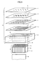
- FIG. 5 shows an exploded perspective view of an ink-jet recording head 40 according to the first embodiment.
- an orifice plate 1 is shown in which, as shown, many ink nozzle holes 2 that discharge ink droplets are formed in rows. Note that the working accuracy in the nozzle holes 2 has a very large influence on the ink discharge performance of the ink-jet recording head 40. In order to control variations in the working accuracy in the nozzle holes 2 among the many nozzle holes 2 at a satisfactorily low level, high working accuracy is required for forming the orifice plate 1.
- the orifice plate 1 is formed by precision press working using a stainless steel plate, or the like.
- a chamber plate 4 and a restrictor plate 7 are positioned with respect to the orifice plate 1, and are joined to the orifice plate 1.
- Pressure chambers 3 that correspond to the respective nozzle holes 2 are formed in the pressure chamber plate 4, and restrictors 6 are formed in the restrictor plate 7.
- the restrictors 6 connect a common ink passage 5 and the pressure chambers 3, and control the flows of the ink into the pressure chambers 3.
- a diaphragm plate 11 has elasticity and includes vibration plates 9 and filters 10.
- the vibration plates 9 efficiently transmit displacement of piezoelectric elements (pressure generation sources) 8 to the pressure chambers 3.
- the filters 10 filter out dirt/dust included in the ink that flows from the common ink passage 5 into the restrictors 6.
- the common ink passage 5 is formed in a housing 12.
- the diagram plate 11 and the housing 12 are also positioned with respect to and joined to the orifice plate 1 in the same way.
- the chamber plate 4, the restrictor plate 7 and the diaphragm plate 11 are formed by an etching process or a nickel electroforming process using stainless steel plates, or the like.
- the housing 12 is formed by a cutting process using a stainless material.
- an ink introducing pipe 13 is joined for introducing the ink from an ink tank (not shown) into the common ink passage 5.
- a piezoelectric element storage part 14 is formed in the housing 12 at a predetermined place for holding the piezoelectric elements 8 therein.
- the piezoelectric elements 8 include many laminated piezoelectric vibrators 15 and a nonconductive attaching member 16 having a conductive pattern part, and the piezoelectric vibrators 15 are attached to the attaching member 16.
- the laminated piezoelectric vibrators 15 that are divided are arranged to correspond to the respective pressure chambers 3.
- external electrodes 17 including individual electrodes and a common electrode for transmitting independent electric signals from a driver IC (not shown) to the laminated piezoelectric vibrators 15 are formed in the attaching member 16.
- a transit interconnection substrate 18 (made of a FPC cable) on which the driver IC is mounted is attached and connected.
- the transit interconnection substrate 18 is connected with a host apparatus (not shown).
- An ink passage unit 19 includes the orifice plate 1, the chamber plate 4, the restrictor plate 7, the diaphragm plate 11 and the housing 12. Further, a head part body includes the ink passage unit 19, the piezoelectric elements 8 and the transit interconnection substrate 18.
- Electric signals are provided to the piezoelectric elements 8 via the driver IC on the transit interconnection substrate 18 and the external electrodes 17, and thereby, distortion occurs in the laminated piezoelectric vibrators 15.
- the vibration plates 9 are deformed, the internal pressures in the pressure chambers 3 are thus changed, and the ink contained in the pressure chambers 3 is discharged as ink droplets from the nozzle holes 2.
- FIG. 6 shows a general configuration diagram showing the entire configuration of an ink-jet recording apparatus according to the first embodiment in which the ink-jet recording heads are mounted.
- a continuous to-be-recorded-on medium (continuous paper sheet) 32 is unwound from a paper supply part 31 at high speed, a desired image is then printed on the continuous to-be-recorded-on medium 32 at an ink-jet recording part 33, and then, the continuous to-be-recorded-on medium 32 is wound onto and is collected by a paper collecting part 34.
- the ink-jet recording part 33 includes an ink tank 35 installed at a body side in the ink-jet recording apparatus; a direct movement guide 36 extending along a width direction (a X-direction) of the to-be-recorded-on medium 32; a carriage 37 reciprocating at high speed along the width directions (X-directions) of the to-be-recorded-on medium 32 along the direct movement guide 36; and a cableveyor (registered trademark) 38.
- plural of the ink-jet recording heads 40 are individually placed and mounted in a staggered arrangement, in such a manner that the orifice plate 1 is placed at the bottom in each of the ink-jet recording heads 40.
- flexible ink supply tubes 41 are provided to connect between the ink tank 35 and the cableveyor 38, and between the cableveyor 38 and the respective ink-jet recording heads 40. In this configuration, the to-be-recorded-on medium 32 is conveyed in the direction Y shown.
- Japanese Laid-Open Patent Application No. 11-320888 and Japanese Laid-Open Patent Application No. 2003-341069 relate to orifice plates such as the orifice plate 1 to be used in such as the ink-jet recording head 40.
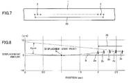
- FIGs. 7 and 8 For the sake of convenience, a problem in the related art will now be described using FIGs. 7 and 8 , assuming that the related art has the same configurations as those shown in FIGs. 5 and 6 that have been described above, as those according to the first embodiment.
- FIG. 7 shows a magnified plan view of a part of an orifice plate 1 according to the related art. As shown, many nozzle holes 2 are formed in a row at predetermined positions, each nozzle hole 2 passing through the orifice plate 1. The nozzle holes 2 are formed in a nozzle hole formation area 20.
- FIG. 8 is a displacement measurement diagram showing a result of measuring displacement at an end of the orifice plate 1, according to the related art, in which nozzle holes 2 are formed in a row by precision press working.
- the displacement measurement was carried out using a NH 3 laser measurement instrument. The measurement was started at a position distant outward by 2 mm from an outermost one 2a of the nozzle holes 2. The measurement intervals are 0.01 mm.
- the displacement of the orifice plate 1 started at the point A, and the displacement curve B can be obtained from connecting the respective displacement points that were obtained from the measurement.
- thick line segments 2a, 2b, ..., 2e indicate the opening directions of the pierced nozzle holes 2 (i.e., the directions along which the respective nozzle holes 2 extend).
- each of the opening directions of the nozzle holes 2a, 2b and 2c in the thus curved (protruded) area is different from the vertical direction and is oblique with respect to the vertical direction, as shown in FIG. 8 .
- the nozzle holes 2, each of which has the opening direction approximately equal to the vertical direction, are the nozzle hole 2e and those (not shown) placed further inside.
- the nozzle hole 2a is away from the displacement start point A only by 1 mm.
- each of the plurality of nozzle holes 2 placed at both of the ends of the row of the nozzle holes 2 is different from the vertical direction and is oblique.
- the positions at which ink droplets discharged through these oblique nozzle holes 2 land vary accordingly, and thus, it may be difficult to obtain a high quality image. This is a problem in the related art.
- An object of the embodiments is to provide liquid droplet discharge heads in each of which it is possible to solve the problem in the related art.
- each of the liquid droplet discharge heads according to the embodiments can discharge liquid droplets in such a manner that the positions at which the liquid droplets thus discharged land on a to-be-landed-on member (to-be-recorded-on medium) do not vary, and it is possible to discharge liquid droplets to cause them to accurately land on the to-be-landed-on member (to-be-recorded-on medium).
- liquid droplet discharge heads each having superior operational reliability, liquid droplet discharge apparatuses including the liquid droplet discharge heads and ink-jet recording apparatuses that are examples of the liquid droplet discharge apparatuses.
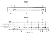
- FIG. 1 shows a magnified plan view of a part of an orifice plate 1 according to the first embodiment.
- FIG. 2 is a displacement measurement diagram showing a result of measuring displacement at an end of the orifice plate 1, according to the first embodiment, in which nozzle holes 2 and dummy depressions (pressed points) 21 are formed in a row by precision press working.
- FIG. 3 shows a magnified cross-sectional view of the nozzle hole 2 formed in the orifice plate 1 and the vicinity thereof according to the first embodiment.
- FIG. 4 shows a magnified cross-sectional view of the dummy depression 21 formed in the orifice plate 1 and the vicinity thereof according to the first embodiment.
- the nozzle holes 2 are formed in a row at predetermined positions on the orifice plate 1.
- the nozzle holes 2 are formed in a nozzle hole formation area 20.
- plural of the dummy depressions 21 in the first embodiment, as shown in FIG. 2 , 10 of the dummy depressions 21 at each end
- the dummy depressions 21 are formed in dummy depression formation areas 22.
- each dummy depression 21 is formed by precision press working using a punch and a die that receives the punch. As shown in FIG. 1 , the shape viewed from the top of each dummy depression 21 is circular, the same as or similar to that of each nozzle hole 2.
- the nozzle holes 2 and the dummy depressions 21 are formed from the same side of the orifice plate 1 (in the first embodiment, from the top side of the orifice plate 1). While the nozzle holes 2 pass through the orifice plate 1 from the top side to the under side as shown in FIG. 3 , the dummy depressions 21 extend from the top side of the orifice plate 1 up to an intermediate position in the thickness direction, and thus, are not through holes.
- the nozzle holes 2 are expressed by ⁇ since they pass through while the dummy depressions 21 are expressed by • since they do not pass through.
- the dummy depression formation area 22 is defined in which the plurality of dummy depressions 21 is placed. Thick line segments shown in the dummy depression formation area 22 denote the respective opening directions of the dummy depressions 21.
- the orifice plate 1 according to the first embodiment is curved to protrude more as the position moves inside more (see the displacement curve B in FIG. 2 ).
- the displacement curve B is approximately level (level part).
- each of the nozzle holes 2 (2a, 2b, 2c and 2d), including the outermost nozzle hole 2a, used to discharge ink droplets has the vertical opening direction.
- the nozzle hole formation area 20 can be made to fall within the level part that remains between the curved parts at both end parts of the orifice plate 1, and thus, the nozzle holes 2 within the nozzle hole formation area 20 have the vertical opening directions. Note that also the other end of the orifice plate 1 has a displacement measurement result the same as or similar to that shown in FIG. 2 .
- each of the nozzle holes in the nozzle hole row that starts at the outermost nozzle hole 2a extends vertically.
- the positions at which ink droplets discharged through these vertical nozzle holes 2 land do not vary accordingly, and thus, it is possible to obtain a high quality image.
- a water repellent film 23 is formed on the side of the orifice plate 1 facing the to-be-recorded-on medium 32.
- the liquid droplet discharge head by which it is possible to solve the above-mentioned problem in the related art.
- the liquid droplet discharge head according to the first embodiment can discharge liquid droplets in such a manner that the positions at which the liquid droplets thus discharged land on a to-be-landed-on member do not vary and it is possible discharge liquid droplets to cause them to accurately land on the to-be-landed-on member.
- the liquid droplet discharge apparatus including the liquid droplet discharge head and the ink-jet recording apparatus as an example of the liquid droplet discharge apparatus.
- liquid droplet discharge head the liquid droplet discharge apparatus and the ink-jet recording apparatus have been described above by the first embodiment, the present invention is not limited to the first embodiment, and variations and modifications may be made without departing from the scope of the present invention.
- the dummy depressions 21 that do not pass through the orifice plate 1 are used as dummy pressed points as mentioned above according to the first embodiment.
- embodiments of the present invention are not limited thereto.
- "dummy holes" that pass through the orifice plate 1 may be formed as the dummy pressed points in the orifice plate 1 in another embodiment.
- the outermost nozzles through which ink droplets are discharged are used as position-adjustment reference holes when the ink-jet recording head is mounted in the ink-jet recording apparatus. Therefore, when such dummy holes are used as the dummy pressed points, the position adjustment may be carried out using an improper through holes. For the purpose of avoiding such a problematic situation, the dummy depressions 21 that do not pass through the orifice plate 1 are more preferable.
- the rows of dummy pressed points are formed in alignment with the nozzle hole row.
- the dummy pressed points may be formed, respectively, at positions somewhat away on both sides of and in parallel with the line of the nozzle hole row, in yet another embodiment.
- many dummy pressed points may be formed, in a random manner, near both the ends (or on both end sides) of the nozzle hole row.
- the cases of the ink-jet recording apparatuses have been described.
- embodiments are not limited thereto.
- the present invention can be applied also to other fields, for example, those of manufacturing display apparatuses such as those using liquid crystals, electroluminescence or the like, manufacturing printed wiring boards on which an ink containing titanium oxide particles is deposited, manufacturing electronic parts/components such as laminated ceramic parts/components or high frequency electronic parts/components manufactured using a high-concentration ink prepared for electronic parts/components which is subject to sedimentation or condensation, and so forth.
Landscapes
- Engineering & Computer Science (AREA)
- Manufacturing & Machinery (AREA)
- Particle Formation And Scattering Control In Inkjet Printers (AREA)
Abstract
Description
- The present invention relates to a liquid droplet discharge head such as an ink-jet recording head used in an ink-jet recording apparatus, and, in particular, to a configuration of an orifice plate to be used in the liquid droplet discharge head.
- High quality in an image to be output is demanded for printing by an ink-jet recording head not only for consumer use but also for industrial use. Further, on-demand printing is requested also in a field of printing for a large signboard, a poster or the like, and thus, on-demand-type ink-jet recording apparatuses are used on many occasions.
- For these ink-jet recording apparatuses, miniaturization of the apparatuses and cost reduction are required. As for the ink-jet recording apparatuses, miniaturization of the ink-jet recording heads by increasing the nozzle mounding density, i.e., reducing the nozzle hole intervals in the nozzle hole rows is required. Also, miniaturization of the ink-jet recording heads by reducing the distances among the plurality of nozzle hole rows is required. Further, an increase in the number of nozzles is also required.
- Furthermore, recently, the number of cases of using the ink-jet recording heads discharging special solutions for forming liquid crystal displays, forming wiring patterns or the like has increased. For the purpose of such patterning, such an orifice plate is required that nozzle holes are formed with high accuracy, since it is necessary to reduce variations in positions at which liquid droplets discharged by the liquid droplet discharge head land on a to-be-landed-on member.
- According to one embodiment of the present invention, a liquid droplet discharge head includes an orifice plate that has a nozzle hole row in which a plurality of nozzle holes is formed in a row by press working. Liquid droplets are discharged to a to-be-landed-on member from the nozzle holes and land on the to-be-landed-on member. In the liquid droplet discharge head, a plurality of dummy pressed points for making uniform opening directions of the nozzle holes is formed on both of end sides of the nozzle hole row in the orifice plate.
- Other objects, features and advantages of the present invention will become more apparent from the following detailed description when read in conjunction with the accompanying drawings.
-
-
FIG. 1 shows a magnified plan view of a part of an orifice plate according to a first embodiment; -
FIG. 2 is a displacement measurement diagram showing a result of measuring displacement at an end of the orifice plate, according to the first embodiment, in which nozzle holes and dummy depressions are formed in a row by precision press working; -
FIG. 3 shows a magnified cross-sectional view of the nozzle hole formed in the orifice plate and the vicinity thereof according to the first embodiment; -
FIG. 4 shows a magnified cross-sectional view of a dummy depression formed in the orifice plate and the vicinity thereof according to the first embodiment; -
FIG. 5 shows an exploded perspective view of an ink-jet recording head according to the first embodiment; -
FIG. 6 is a general configuration diagram showing the entire configuration of an ink-jet recording apparatus according to the first embodiment in which ink-jet recording heads are mounted; -
FIG. 7 shows a magnified plan view of a part of an orifice plate according to the related art; and -
FIG. 8 is a displacement measurement diagram showing a result of measuring displacement at an end of the orifice plate, according to the related art, in which nozzle holes are formed in a row by precision press working. -
FIG. 5 shows an exploded perspective view of an ink-jet recording head 40 according to the first embodiment. - In
FIG. 5 , anorifice plate 1 is shown in which, as shown, manyink nozzle holes 2 that discharge ink droplets are formed in rows. Note that the working accuracy in thenozzle holes 2 has a very large influence on the ink discharge performance of the ink-jet recording head 40. In order to control variations in the working accuracy in thenozzle holes 2 among themany nozzle holes 2 at a satisfactorily low level, high working accuracy is required for forming theorifice plate 1. For this purpose, theorifice plate 1 is formed by precision press working using a stainless steel plate, or the like. - A
chamber plate 4 and arestrictor plate 7 are positioned with respect to theorifice plate 1, and are joined to theorifice plate 1.Pressure chambers 3 that correspond to therespective nozzle holes 2 are formed in thepressure chamber plate 4, andrestrictors 6 are formed in therestrictor plate 7. Therestrictors 6 connect acommon ink passage 5 and thepressure chambers 3, and control the flows of the ink into thepressure chambers 3. - A
diaphragm plate 11 has elasticity and includesvibration plates 9 andfilters 10. Thevibration plates 9 efficiently transmit displacement of piezoelectric elements (pressure generation sources) 8 to thepressure chambers 3. Thefilters 10 filter out dirt/dust included in the ink that flows from thecommon ink passage 5 into therestrictors 6. Thecommon ink passage 5 is formed in ahousing 12. Thediagram plate 11 and thehousing 12 are also positioned with respect to and joined to theorifice plate 1 in the same way. - The
chamber plate 4, therestrictor plate 7 and thediaphragm plate 11 are formed by an etching process or a nickel electroforming process using stainless steel plates, or the like. - The
housing 12 is formed by a cutting process using a stainless material. To thehousing 12, anink introducing pipe 13 is joined for introducing the ink from an ink tank (not shown) into thecommon ink passage 5. Further, a piezoelectricelement storage part 14 is formed in thehousing 12 at a predetermined place for holding thepiezoelectric elements 8 therein. - The
piezoelectric elements 8 include many laminatedpiezoelectric vibrators 15 and a nonconductive attachingmember 16 having a conductive pattern part, and thepiezoelectric vibrators 15 are attached to the attachingmember 16. The laminatedpiezoelectric vibrators 15 that are divided are arranged to correspond to therespective pressure chambers 3. Alsoexternal electrodes 17 including individual electrodes and a common electrode for transmitting independent electric signals from a driver IC (not shown) to the laminatedpiezoelectric vibrators 15 are formed in the attachingmember 16. - To the side surface of the attaching
member 16 on which theexternal electrodes 17 are formed, a transit interconnection substrate 18 (made of a FPC cable) on which the driver IC is mounted is attached and connected. Thetransit interconnection substrate 18 is connected with a host apparatus (not shown). - An
ink passage unit 19 includes theorifice plate 1, thechamber plate 4, therestrictor plate 7, thediaphragm plate 11 and thehousing 12. Further, a head part body includes theink passage unit 19, thepiezoelectric elements 8 and thetransit interconnection substrate 18. - Electric signals are provided to the
piezoelectric elements 8 via the driver IC on thetransit interconnection substrate 18 and theexternal electrodes 17, and thereby, distortion occurs in the laminatedpiezoelectric vibrators 15. As a result, thevibration plates 9 are deformed, the internal pressures in thepressure chambers 3 are thus changed, and the ink contained in thepressure chambers 3 is discharged as ink droplets from thenozzle holes 2. -
FIG. 6 shows a general configuration diagram showing the entire configuration of an ink-jet recording apparatus according to the first embodiment in which the ink-jet recording heads are mounted. - As shown in
FIG. 6 , a continuous to-be-recorded-on medium (continuous paper sheet) 32 is unwound from apaper supply part 31 at high speed, a desired image is then printed on the continuous to-be-recorded-onmedium 32 at an ink-jet recording part 33, and then, the continuous to-be-recorded-onmedium 32 is wound onto and is collected by apaper collecting part 34. - The ink-
jet recording part 33 includes anink tank 35 installed at a body side in the ink-jet recording apparatus; adirect movement guide 36 extending along a width direction (a X-direction) of the to-be-recorded-onmedium 32; acarriage 37 reciprocating at high speed along the width directions (X-directions) of the to-be-recorded-onmedium 32 along thedirect movement guide 36; and a cableveyor (registered trademark) 38. - On a
flat part 39 facing the to-be-recorded-onmedium 32 in thecarriage 37, plural of the ink-jet recording heads 40, as shown inFIG. 6 , are individually placed and mounted in a staggered arrangement, in such a manner that theorifice plate 1 is placed at the bottom in each of the ink-jet recording heads 40. As shown inFIG. 6 , flexibleink supply tubes 41 are provided to connect between theink tank 35 and thecableveyor 38, and between thecableveyor 38 and the respective ink-jet recording heads 40. In this configuration, the to-be-recorded-onmedium 32 is conveyed in the direction Y shown. - Note that, for example, Japanese Laid-Open Patent Application No.
11-320888 2003-341069 orifice plate 1 to be used in such as the ink-jet recording head 40. - For the sake of convenience, a problem in the related art will now be described using
FIGs. 7 and 8 , assuming that the related art has the same configurations as those shown inFIGs. 5 and6 that have been described above, as those according to the first embodiment. -
FIG. 7 shows a magnified plan view of a part of anorifice plate 1 according to the related art. As shown,many nozzle holes 2 are formed in a row at predetermined positions, eachnozzle hole 2 passing through theorifice plate 1. Thenozzle holes 2 are formed in a nozzlehole formation area 20. -
FIG. 8 is a displacement measurement diagram showing a result of measuring displacement at an end of theorifice plate 1, according to the related art, in which nozzle holes 2 are formed in a row by precision press working. The displacement measurement was carried out using a NH3 laser measurement instrument. The measurement was started at a position distant outward by 2 mm from an outermost one 2a of the nozzle holes 2. The measurement intervals are 0.01 mm. The displacement of theorifice plate 1 started at the point A, and the displacement curve B can be obtained from connecting the respective displacement points that were obtained from the measurement. Further,thick line segments respective nozzle holes 2 extend). - As shown in
FIG. 8 , in the case where themany nozzle holes 2 are formed in a row in theorifice plate 1, theorifice plate 1 is curved to protrude more as the position moves inside more (see the displacement curve B). Then, each of the opening directions of thenozzle holes FIG. 8 . The nozzle holes 2, each of which has the opening direction approximately equal to the vertical direction, are thenozzle hole 2e and those (not shown) placed further inside. - In the example of
FIG. 8 , thenozzle hole 2a is away from the displacement start point A only by 1 mm. - Also at the other end of the
orifice plate 1, a similar curved part in which theorifice plate 1 was curved to protrude exists, and the opening direction of each of the nozzle holes 2 placed there is oblique with respect to the vertical direction. - Thus, the opening direction of each of the plurality of
nozzle holes 2 placed at both of the ends of the row of the nozzle holes 2 is different from the vertical direction and is oblique. As a result, the positions at which ink droplets discharged through these oblique nozzle holes 2 land vary accordingly, and thus, it may be difficult to obtain a high quality image. This is a problem in the related art. - An object of the embodiments is to provide liquid droplet discharge heads in each of which it is possible to solve the problem in the related art. As a result, each of the liquid droplet discharge heads according to the embodiments can discharge liquid droplets in such a manner that the positions at which the liquid droplets thus discharged land on a to-be-landed-on member (to-be-recorded-on medium) do not vary, and it is possible to discharge liquid droplets to cause them to accurately land on the to-be-landed-on member (to-be-recorded-on medium). Thus, it is possible to provide liquid droplet discharge heads each having superior operational reliability, liquid droplet discharge apparatuses including the liquid droplet discharge heads and ink-jet recording apparatuses that are examples of the liquid droplet discharge apparatuses.
-
FIG. 1 shows a magnified plan view of a part of anorifice plate 1 according to the first embodiment.FIG. 2 is a displacement measurement diagram showing a result of measuring displacement at an end of theorifice plate 1, according to the first embodiment, in which nozzle holes 2 and dummy depressions (pressed points) 21 are formed in a row by precision press working.FIG. 3 shows a magnified cross-sectional view of thenozzle hole 2 formed in theorifice plate 1 and the vicinity thereof according to the first embodiment.FIG. 4 shows a magnified cross-sectional view of thedummy depression 21 formed in theorifice plate 1 and the vicinity thereof according to the first embodiment. - As shown in
FIG. 1 , many of the nozzle holes 2 are formed in a row at predetermined positions on theorifice plate 1. Thus, the nozzle holes 2 are formed in a nozzlehole formation area 20. Further, as shown inFIG. 1 , plural of the dummy depressions 21 (in the first embodiment, as shown inFIG. 2 , 10 of thedummy depressions 21 at each end) are formed in respective rows in alignment with the row of the nozzle holes 2 (nozzle hole row) near both of the ends (or on both of the end sides) of the nozzle hole row. As shown inFIG. 1 , thedummy depressions 21 are formed in dummydepression formation areas 22. - As the material of the
orifice plate 1, a stainless steel plate is used, and the nozzle holes 2 and thedummy depressions 21 are formed by precision press working using a punch and a die that receives the punch. As shown inFIG. 1 , the shape viewed from the top of eachdummy depression 21 is circular, the same as or similar to that of eachnozzle hole 2. - The nozzle holes 2 and the
dummy depressions 21 are formed from the same side of the orifice plate 1 (in the first embodiment, from the top side of the orifice plate 1). While the nozzle holes 2 pass through theorifice plate 1 from the top side to the under side as shown inFIG. 3 , thedummy depressions 21 extend from the top side of theorifice plate 1 up to an intermediate position in the thickness direction, and thus, are not through holes. InFIG. 1 , the nozzle holes 2 are expressed by ○ since they pass through while thedummy depressions 21 are expressed by • since they do not pass through. - The displacement measurement of the
orifice plate 1 shown inFIG. 2 was carried out under the same conditions as those in the displacement measurement of theorifice plate 1 in the related art described above usingFIG. 8 . - As shown in
FIG. 2 , at an end of the nozzlehole formation area 20, the dummydepression formation area 22 is defined in which the plurality ofdummy depressions 21 is placed. Thick line segments shown in the dummydepression formation area 22 denote the respective opening directions of the dummy depressions 21. - Basically in the same way as that in
FIG. 8 , theorifice plate 1 according to the first embodiment is curved to protrude more as the position moves inside more (see the displacement curve B inFIG. 2 ). However, a little inside the thus curved part (precisely, inside the point that is away inside from the displacement start point A by 2 mm), the displacement curve B is approximately level (level part). - Further, the
outermost nozzle hole 2a in the nozzle hole row is away from the displacement start point A by more than 2 mm on theorifice plate 1, and each of thedummy depressions 21 placed within the dummydepression formation area 22 and not used to discharge ink droplets has the oblique opening direction. In contrast thereto, each of the nozzle holes 2 (2a, 2b, 2c and 2d), including theoutermost nozzle hole 2a, used to discharge ink droplets has the vertical opening direction. - Thus, according to the first embodiment, it is possible to elongate the distance from the displacement start point A to the
outermost nozzle hole 2a twice in comparison to the related art shown inFIG. 8 . As a result, the nozzlehole formation area 20 can be made to fall within the level part that remains between the curved parts at both end parts of theorifice plate 1, and thus, the nozzle holes 2 within the nozzlehole formation area 20 have the vertical opening directions. Note that also the other end of theorifice plate 1 has a displacement measurement result the same as or similar to that shown inFIG. 2 . - Thus, each of the nozzle holes in the nozzle hole row that starts at the
outermost nozzle hole 2a extends vertically. As a result, the positions at which ink droplets discharged through these vertical nozzle holes 2 land do not vary accordingly, and thus, it is possible to obtain a high quality image. - Note that as shown in
FIGs. 3 and 4 , awater repellent film 23 is formed on the side of theorifice plate 1 facing the to-be-recorded-onmedium 32. - According to the first embodiment, it is possible to provide the liquid droplet discharge head by which it is possible to solve the above-mentioned problem in the related art. As a result, the liquid droplet discharge head according to the first embodiment can discharge liquid droplets in such a manner that the positions at which the liquid droplets thus discharged land on a to-be-landed-on member do not vary and it is possible discharge liquid droplets to cause them to accurately land on the to-be-landed-on member. Thus, it is possible to provide the liquid droplet discharge head having superior operational reliability, the liquid droplet discharge apparatus including the liquid droplet discharge head and the ink-jet recording apparatus as an example of the liquid droplet discharge apparatus.
- Although the liquid droplet discharge head, the liquid droplet discharge apparatus and the ink-jet recording apparatus have been described above by the first embodiment, the present invention is not limited to the first embodiment, and variations and modifications may be made without departing from the scope of the present invention.
- For example, the
dummy depressions 21 that do not pass through theorifice plate 1 are used as dummy pressed points as mentioned above according to the first embodiment. However, embodiments of the present invention are not limited thereto. Instead of the dummy depressions 21, "dummy holes" that pass through theorifice plate 1 may be formed as the dummy pressed points in theorifice plate 1 in another embodiment. - However, the outermost nozzles through which ink droplets are discharged are used as position-adjustment reference holes when the ink-jet recording head is mounted in the ink-jet recording apparatus. Therefore, when such dummy holes are used as the dummy pressed points, the position adjustment may be carried out using an improper through holes. For the purpose of avoiding such a problematic situation, the
dummy depressions 21 that do not pass through theorifice plate 1 are more preferable. - Further, according to the above-mentioned embodiments, the rows of dummy pressed points are formed in alignment with the nozzle hole row. However, embodiments of the present invention are not limited thereto. For example, instead of the above-mentioned arrangement, the dummy pressed points may be formed, respectively, at positions somewhat away on both sides of and in parallel with the line of the nozzle hole row, in yet another embodiment. In further another embodiment, many dummy pressed points may be formed, in a random manner, near both the ends (or on both end sides) of the nozzle hole row.
- Furthermore, in the above-mentioned embodiments, the cases of the ink-jet recording apparatuses have been described. However, embodiments are not limited thereto. The present invention can be applied also to other fields, for example, those of manufacturing display apparatuses such as those using liquid crystals, electroluminescence or the like, manufacturing printed wiring boards on which an ink containing titanium oxide particles is deposited, manufacturing electronic parts/components such as laminated ceramic parts/components or high frequency electronic parts/components manufactured using a high-concentration ink prepared for electronic parts/components which is subject to sedimentation or condensation, and so forth.
- The present patent application is based on and claims the benefit of priority of Japanese Priority Application No.
2012-225182 filed on October 10, 2012
Claims (8)
- A liquid droplet discharge head comprising:an orifice plate that has a nozzle hole row in which a plurality of nozzle holes is formed in a row by press working, whereinliquid droplets are discharged to a to-be-landed-on member from the nozzle holes and land on the to-be-landed-on member, anda plurality of dummy pressed points for making uniform opening directions of the nozzle holes is formed on both of end sides of the nozzle hole row in the orifice plate.
- The liquid droplet discharge head as claimed in claim 1, wherein
the nozzle holes and the dummy pressed points are formed from the same side of the orifice plate. - The liquid droplet discharge head as claimed in claim 1 or 2, wherein
the dummy pressed points are formed in rows that extend in the same direction as that of the nozzle hole row. - The liquid droplet discharge head as claimed in claim 3, wherein
the rows of the dummy pressed points are in alignment with the nozzle hole row. - The liquid droplet discharge head as claimed in any one of claims 1-4, wherein
the dummy pressed points are dummy depressions that do not pass through the orifice plate from a top side to an under side. - The liquid droplet discharge head as claimed in any one of claims 1-5, wherein
as a result of the dummy pressed points being formed in the orifice plate on both of the end sides of the nozzle hole row by the press working, respective curved parts are formed at both of end parts and a level part remains between the curved parts, and
areas in which the dummy pressed points are formed in the orifice plate are determined such that all of the nozzle holes are formed within the level part. - A liquid droplet discharge apparatus, comprising:the liquid droplet discharge head claimed in any one of claims 1-6.
- An ink-jet recording apparatus as the liquid droplet discharge apparatus claimed in claim 7, comprising:an ink-jet recording head as the liquid droplet discharge head including the orifice plate that has the nozzle hole row including the plurality of nozzle holes, whereinink droplets as the liquid droplets are discharged to a to-be-recorded-on medium as the to-be-landed-on member from the nozzle holes and land on the to-be-recorded-on medium.
Applications Claiming Priority (1)
| Application Number | Priority Date | Filing Date | Title |
|---|---|---|---|
| JP2012225182A JP6089561B2 (en) | 2012-10-10 | 2012-10-10 | Droplet discharge head, droplet discharge apparatus including the same, and ink jet recording apparatus |
Publications (2)
| Publication Number | Publication Date |
|---|---|
| EP2719536A1 true EP2719536A1 (en) | 2014-04-16 |
| EP2719536B1 EP2719536B1 (en) | 2015-01-07 |
Family
ID=49237057
Family Applications (1)
| Application Number | Title | Priority Date | Filing Date |
|---|---|---|---|
| EP13185206.3A Active EP2719536B1 (en) | 2012-10-10 | 2013-09-19 | Liquid droplet discharge head, liquid droplet discharge apparatus including the same, and ink-jet recording apparatus as the liquid droplet discharge apparatus |
Country Status (4)
| Country | Link |
|---|---|
| US (1) | US9186895B2 (en) |
| EP (1) | EP2719536B1 (en) |
| JP (1) | JP6089561B2 (en) |
| CN (1) | CN103722885B (en) |
Families Citing this family (1)
| Publication number | Priority date | Publication date | Assignee | Title |
|---|---|---|---|---|
| US11712892B2 (en) * | 2020-03-30 | 2023-08-01 | Brother Kogyo Kabushiki Kaisha | Head system, liquid supply system, printing apparatus, and liquid flow method |
Citations (6)
| Publication number | Priority date | Publication date | Assignee | Title |
|---|---|---|---|---|
| US5988786A (en) * | 1997-06-30 | 1999-11-23 | Hewlett-Packard Company | Articulated stress relief of an orifice membrane |
| JPH11320888A (en) | 1998-05-19 | 1999-11-24 | Canon Inc | Inkjet recording head |
| US6431682B1 (en) * | 1999-05-27 | 2002-08-13 | Canon Kabushiki Kaisha | Liquid discharge head, method of manufacturing the liquid discharge head, and liquid discharge recording apparatus using the liquid discharge head |
| JP2003341069A (en) | 2002-05-24 | 2003-12-03 | Sii Printek Inc | Nozzle plate, its producing method and inkjet head |
| JP2009179032A (en) * | 2008-02-01 | 2009-08-13 | Seiko Epson Corp | Metal plate manufacturing method and liquid jet head |
| US20100026752A1 (en) * | 2008-07-29 | 2010-02-04 | Seiko Epson Corporation | Method of manufacturing liquid ejecting head and liquid ejecting apparatus |
Family Cites Families (14)
| Publication number | Priority date | Publication date | Assignee | Title |
|---|---|---|---|---|
| US6328397B1 (en) * | 1998-09-07 | 2001-12-11 | Hitachi Koki Co., Ltd. | Drive voltage adjusting method for an on-demand multi-nozzle ink jet head |
| US6745467B1 (en) * | 1999-02-10 | 2004-06-08 | Canon Kabushiki Kaisha | Method of producing a liquid discharge head |
| EP1657064B1 (en) * | 2000-08-09 | 2007-05-23 | Sony Corporation | Print head, manufacturing method therefor and printer |
| CN1189325C (en) * | 2001-07-09 | 2005-02-16 | 株式会社理光 | Liquid drop spray head and ink-jet recording apparatus |
| JP3794401B2 (en) * | 2002-08-23 | 2006-07-05 | セイコーエプソン株式会社 | Method for manufacturing liquid jet head |
| EP1426185B1 (en) * | 2002-12-05 | 2007-11-28 | Toshiba Tec Kabushiki Kaisha | Ink jet head and ink jet printer |
| JP4561228B2 (en) * | 2004-08-11 | 2010-10-13 | セイコーエプソン株式会社 | Liquid ejecting head unit and liquid ejecting head alignment method |
| JP4581579B2 (en) * | 2004-09-14 | 2010-11-17 | セイコーエプソン株式会社 | Metal substrate processing method and liquid jet head manufacturing method |
| CN101102897A (en) * | 2004-11-19 | 2008-01-09 | 爱克发印艺公司 | Improved method of bonding nozzle plates to inkjet printheads |
| JP4370349B2 (en) * | 2007-08-01 | 2009-11-25 | シャープ株式会社 | Ink jet head and manufacturing method thereof |
| JP2010137487A (en) * | 2008-12-15 | 2010-06-24 | Seiko Epson Corp | Liquid discharge head, liquid discharge head unit, and liquid discharge device |
| JP5585209B2 (en) * | 2009-05-28 | 2014-09-10 | 株式会社リコー | Electromechanical transducer manufacturing method, electromechanical transducer manufactured by the manufacturing method, droplet ejection head, and droplet ejection apparatus |
| JP5515469B2 (en) * | 2009-07-10 | 2014-06-11 | 株式会社リコー | Droplet discharge head, manufacturing method thereof, and image forming apparatus |
| JP2011183728A (en) * | 2010-03-10 | 2011-09-22 | Ricoh Co Ltd | Nozzle plate, method for manufacturing nozzle plate, liquid discharging head, and image forming apparatus |
-
2012
- 2012-10-10 JP JP2012225182A patent/JP6089561B2/en active Active
-
2013
- 2013-09-19 EP EP13185206.3A patent/EP2719536B1/en active Active
- 2013-09-27 US US14/039,257 patent/US9186895B2/en active Active
- 2013-09-29 CN CN201310455271.1A patent/CN103722885B/en active Active
Patent Citations (6)
| Publication number | Priority date | Publication date | Assignee | Title |
|---|---|---|---|---|
| US5988786A (en) * | 1997-06-30 | 1999-11-23 | Hewlett-Packard Company | Articulated stress relief of an orifice membrane |
| JPH11320888A (en) | 1998-05-19 | 1999-11-24 | Canon Inc | Inkjet recording head |
| US6431682B1 (en) * | 1999-05-27 | 2002-08-13 | Canon Kabushiki Kaisha | Liquid discharge head, method of manufacturing the liquid discharge head, and liquid discharge recording apparatus using the liquid discharge head |
| JP2003341069A (en) | 2002-05-24 | 2003-12-03 | Sii Printek Inc | Nozzle plate, its producing method and inkjet head |
| JP2009179032A (en) * | 2008-02-01 | 2009-08-13 | Seiko Epson Corp | Metal plate manufacturing method and liquid jet head |
| US20100026752A1 (en) * | 2008-07-29 | 2010-02-04 | Seiko Epson Corporation | Method of manufacturing liquid ejecting head and liquid ejecting apparatus |
Also Published As
| Publication number | Publication date |
|---|---|
| US20140098162A1 (en) | 2014-04-10 |
| CN103722885A (en) | 2014-04-16 |
| JP2014076574A (en) | 2014-05-01 |
| EP2719536B1 (en) | 2015-01-07 |
| JP6089561B2 (en) | 2017-03-08 |
| US9186895B2 (en) | 2015-11-17 |
| CN103722885B (en) | 2015-10-28 |
Similar Documents
| Publication | Publication Date | Title |
|---|---|---|
| USRE47749E1 (en) | Liquid-ejecting head and liquid-ejecting apparatus | |
| US20120182354A1 (en) | Liquid-ejecting head and liquid-ejecting apparatus | |
| US20170368820A1 (en) | Liquid discharge head and recording device using the same | |
| US9168747B2 (en) | Multi-layer electroformed nozzle plate with attenuation pockets | |
| EP1275507A1 (en) | Liquid drop jet head and ink jet recording apparatus | |
| JP6272480B2 (en) | Liquid discharge head and recording apparatus using the same | |
| CN101503026B (en) | Liquid ejection head and liquid ejection device | |
| JP4258605B2 (en) | Liquid ejecting head and liquid ejecting apparatus | |
| US8820905B2 (en) | Liquid ejecting head and liquid ejecting apparatus | |
| US20080239023A1 (en) | Liquid ejecting head | |
| EP2915670B1 (en) | Liquid jet head and liquid jet apparatus | |
| US7717545B2 (en) | Liquid ejecting head and liquid ejecting apparatus | |
| EP2719536B1 (en) | Liquid droplet discharge head, liquid droplet discharge apparatus including the same, and ink-jet recording apparatus as the liquid droplet discharge apparatus | |
| JP5163784B2 (en) | Droplet ejection device and liquid transfer device | |
| JP5218730B2 (en) | Liquid ejecting head and liquid ejecting apparatus | |
| JP6567933B2 (en) | Liquid discharge head and recording apparatus | |
| EP1733883A2 (en) | Liquid discharge head and recording device | |
| JP6119173B2 (en) | Liquid ejecting head module and liquid ejecting apparatus | |
| JP2011218750A (en) | Positioning mechanism of liquid ejection head unit, liquid ejection head unit, liquid ejector, and method of manufacturing liquid ejection head unit | |
| JP2011167881A (en) | Liquid ejection head and liquid ejection apparatus | |
| JP6633424B2 (en) | Liquid ejection head and recording apparatus using the same | |
| JP5821547B2 (en) | Liquid ejecting head module manufacturing method, liquid ejecting head module, and liquid ejecting apparatus | |
| JP2009012369A (en) | Fluid ejecting apparatus and fluid ejecting method | |
| EP3300893A1 (en) | Plate body, liquid ejection head, and liquid ejection recording apparatus | |
| US12528289B2 (en) | Liquid droplet discharging apparatus |
Legal Events
| Date | Code | Title | Description |
|---|---|---|---|
| PUAI | Public reference made under article 153(3) epc to a published international application that has entered the european phase |
Free format text: ORIGINAL CODE: 0009012 |
|
| 17P | Request for examination filed |
Effective date: 20130919 |
|
| AK | Designated contracting states |
Kind code of ref document: A1 Designated state(s): AL AT BE BG CH CY CZ DE DK EE ES FI FR GB GR HR HU IE IS IT LI LT LU LV MC MK MT NL NO PL PT RO RS SE SI SK SM TR |
|
| AX | Request for extension of the european patent |
Extension state: BA ME |
|
| GRAP | Despatch of communication of intention to grant a patent |
Free format text: ORIGINAL CODE: EPIDOSNIGR1 |
|
| INTG | Intention to grant announced |
Effective date: 20140822 |
|
| GRAS | Grant fee paid |
Free format text: ORIGINAL CODE: EPIDOSNIGR3 |
|
| GRAA | (expected) grant |
Free format text: ORIGINAL CODE: 0009210 |
|
| AK | Designated contracting states |
Kind code of ref document: B1 Designated state(s): AL AT BE BG CH CY CZ DE DK EE ES FI FR GB GR HR HU IE IS IT LI LT LU LV MC MK MT NL NO PL PT RO RS SE SI SK SM TR |
|
| REG | Reference to a national code |
Ref country code: GB Ref legal event code: FG4D |
|
| REG | Reference to a national code |
Ref country code: CH Ref legal event code: EP |
|
| REG | Reference to a national code |
Ref country code: IE Ref legal event code: FG4D |
|
| REG | Reference to a national code |
Ref country code: AT Ref legal event code: REF Ref document number: 705397 Country of ref document: AT Kind code of ref document: T Effective date: 20150215 |
|
| REG | Reference to a national code |
Ref country code: DE Ref legal event code: R096 Ref document number: 602013000803 Country of ref document: DE Effective date: 20150219 |
|
| REG | Reference to a national code |
Ref country code: NL Ref legal event code: VDEP Effective date: 20150107 |
|
| REG | Reference to a national code |
Ref country code: AT Ref legal event code: MK05 Ref document number: 705397 Country of ref document: AT Kind code of ref document: T Effective date: 20150107 |
|
| REG | Reference to a national code |
Ref country code: LT Ref legal event code: MG4D |
|
| PG25 | Lapsed in a contracting state [announced via postgrant information from national office to epo] |
Ref country code: ES Free format text: LAPSE BECAUSE OF FAILURE TO SUBMIT A TRANSLATION OF THE DESCRIPTION OR TO PAY THE FEE WITHIN THE PRESCRIBED TIME-LIMIT Effective date: 20150107 Ref country code: HR Free format text: LAPSE BECAUSE OF FAILURE TO SUBMIT A TRANSLATION OF THE DESCRIPTION OR TO PAY THE FEE WITHIN THE PRESCRIBED TIME-LIMIT Effective date: 20150107 Ref country code: FI Free format text: LAPSE BECAUSE OF FAILURE TO SUBMIT A TRANSLATION OF THE DESCRIPTION OR TO PAY THE FEE WITHIN THE PRESCRIBED TIME-LIMIT Effective date: 20150107 Ref country code: LT Free format text: LAPSE BECAUSE OF FAILURE TO SUBMIT A TRANSLATION OF THE DESCRIPTION OR TO PAY THE FEE WITHIN THE PRESCRIBED TIME-LIMIT Effective date: 20150107 Ref country code: BG Free format text: LAPSE BECAUSE OF FAILURE TO SUBMIT A TRANSLATION OF THE DESCRIPTION OR TO PAY THE FEE WITHIN THE PRESCRIBED TIME-LIMIT Effective date: 20150407 Ref country code: SE Free format text: LAPSE BECAUSE OF FAILURE TO SUBMIT A TRANSLATION OF THE DESCRIPTION OR TO PAY THE FEE WITHIN THE PRESCRIBED TIME-LIMIT Effective date: 20150107 Ref country code: NO Free format text: LAPSE BECAUSE OF FAILURE TO SUBMIT A TRANSLATION OF THE DESCRIPTION OR TO PAY THE FEE WITHIN THE PRESCRIBED TIME-LIMIT Effective date: 20150407 |
|
| PG25 | Lapsed in a contracting state [announced via postgrant information from national office to epo] |
Ref country code: NL Free format text: LAPSE BECAUSE OF FAILURE TO SUBMIT A TRANSLATION OF THE DESCRIPTION OR TO PAY THE FEE WITHIN THE PRESCRIBED TIME-LIMIT Effective date: 20150107 Ref country code: PL Free format text: LAPSE BECAUSE OF FAILURE TO SUBMIT A TRANSLATION OF THE DESCRIPTION OR TO PAY THE FEE WITHIN THE PRESCRIBED TIME-LIMIT Effective date: 20150107 Ref country code: RS Free format text: LAPSE BECAUSE OF FAILURE TO SUBMIT A TRANSLATION OF THE DESCRIPTION OR TO PAY THE FEE WITHIN THE PRESCRIBED TIME-LIMIT Effective date: 20150107 Ref country code: AT Free format text: LAPSE BECAUSE OF FAILURE TO SUBMIT A TRANSLATION OF THE DESCRIPTION OR TO PAY THE FEE WITHIN THE PRESCRIBED TIME-LIMIT Effective date: 20150107 Ref country code: GR Free format text: LAPSE BECAUSE OF FAILURE TO SUBMIT A TRANSLATION OF THE DESCRIPTION OR TO PAY THE FEE WITHIN THE PRESCRIBED TIME-LIMIT Effective date: 20150408 Ref country code: LV Free format text: LAPSE BECAUSE OF FAILURE TO SUBMIT A TRANSLATION OF THE DESCRIPTION OR TO PAY THE FEE WITHIN THE PRESCRIBED TIME-LIMIT Effective date: 20150107 Ref country code: IS Free format text: LAPSE BECAUSE OF FAILURE TO SUBMIT A TRANSLATION OF THE DESCRIPTION OR TO PAY THE FEE WITHIN THE PRESCRIBED TIME-LIMIT Effective date: 20150507 |
|
| REG | Reference to a national code |
Ref country code: DE Ref legal event code: R097 Ref document number: 602013000803 Country of ref document: DE |
|
| PG25 | Lapsed in a contracting state [announced via postgrant information from national office to epo] |
Ref country code: EE Free format text: LAPSE BECAUSE OF FAILURE TO SUBMIT A TRANSLATION OF THE DESCRIPTION OR TO PAY THE FEE WITHIN THE PRESCRIBED TIME-LIMIT Effective date: 20150107 Ref country code: CZ Free format text: LAPSE BECAUSE OF FAILURE TO SUBMIT A TRANSLATION OF THE DESCRIPTION OR TO PAY THE FEE WITHIN THE PRESCRIBED TIME-LIMIT Effective date: 20150107 Ref country code: DK Free format text: LAPSE BECAUSE OF FAILURE TO SUBMIT A TRANSLATION OF THE DESCRIPTION OR TO PAY THE FEE WITHIN THE PRESCRIBED TIME-LIMIT Effective date: 20150107 Ref country code: SK Free format text: LAPSE BECAUSE OF FAILURE TO SUBMIT A TRANSLATION OF THE DESCRIPTION OR TO PAY THE FEE WITHIN THE PRESCRIBED TIME-LIMIT Effective date: 20150107 Ref country code: RO Free format text: LAPSE BECAUSE OF FAILURE TO SUBMIT A TRANSLATION OF THE DESCRIPTION OR TO PAY THE FEE WITHIN THE PRESCRIBED TIME-LIMIT Effective date: 20150107 |
|
| PLBE | No opposition filed within time limit |
Free format text: ORIGINAL CODE: 0009261 |
|
| STAA | Information on the status of an ep patent application or granted ep patent |
Free format text: STATUS: NO OPPOSITION FILED WITHIN TIME LIMIT |
|
| 26N | No opposition filed |
Effective date: 20151008 |
|
| PG25 | Lapsed in a contracting state [announced via postgrant information from national office to epo] |
Ref country code: SI Free format text: LAPSE BECAUSE OF FAILURE TO SUBMIT A TRANSLATION OF THE DESCRIPTION OR TO PAY THE FEE WITHIN THE PRESCRIBED TIME-LIMIT Effective date: 20150107 |
|
| PG25 | Lapsed in a contracting state [announced via postgrant information from national office to epo] |
Ref country code: LU Free format text: LAPSE BECAUSE OF FAILURE TO SUBMIT A TRANSLATION OF THE DESCRIPTION OR TO PAY THE FEE WITHIN THE PRESCRIBED TIME-LIMIT Effective date: 20150919 Ref country code: MC Free format text: LAPSE BECAUSE OF FAILURE TO SUBMIT A TRANSLATION OF THE DESCRIPTION OR TO PAY THE FEE WITHIN THE PRESCRIBED TIME-LIMIT Effective date: 20150107 |
|
| PG25 | Lapsed in a contracting state [announced via postgrant information from national office to epo] |
Ref country code: BE Free format text: LAPSE BECAUSE OF FAILURE TO SUBMIT A TRANSLATION OF THE DESCRIPTION OR TO PAY THE FEE WITHIN THE PRESCRIBED TIME-LIMIT Effective date: 20150107 |
|
| REG | Reference to a national code |
Ref country code: IE Ref legal event code: MM4A |
|
| PG25 | Lapsed in a contracting state [announced via postgrant information from national office to epo] |
Ref country code: IE Free format text: LAPSE BECAUSE OF NON-PAYMENT OF DUE FEES Effective date: 20150919 |
|
| REG | Reference to a national code |
Ref country code: FR Ref legal event code: PLFP Year of fee payment: 4 |
|
| PG25 | Lapsed in a contracting state [announced via postgrant information from national office to epo] |
Ref country code: MT Free format text: LAPSE BECAUSE OF FAILURE TO SUBMIT A TRANSLATION OF THE DESCRIPTION OR TO PAY THE FEE WITHIN THE PRESCRIBED TIME-LIMIT Effective date: 20150107 |
|
| REG | Reference to a national code |
Ref country code: CH Ref legal event code: PL |
|
| PG25 | Lapsed in a contracting state [announced via postgrant information from national office to epo] |
Ref country code: HU Free format text: LAPSE BECAUSE OF FAILURE TO SUBMIT A TRANSLATION OF THE DESCRIPTION OR TO PAY THE FEE WITHIN THE PRESCRIBED TIME-LIMIT; INVALID AB INITIO Effective date: 20130919 |
|
| PG25 | Lapsed in a contracting state [announced via postgrant information from national office to epo] |
Ref country code: CY Free format text: LAPSE BECAUSE OF FAILURE TO SUBMIT A TRANSLATION OF THE DESCRIPTION OR TO PAY THE FEE WITHIN THE PRESCRIBED TIME-LIMIT Effective date: 20150107 |
|
| PG25 | Lapsed in a contracting state [announced via postgrant information from national office to epo] |
Ref country code: LI Free format text: LAPSE BECAUSE OF NON-PAYMENT OF DUE FEES Effective date: 20160930 Ref country code: CH Free format text: LAPSE BECAUSE OF NON-PAYMENT OF DUE FEES Effective date: 20160930 |
|
| REG | Reference to a national code |
Ref country code: FR Ref legal event code: PLFP Year of fee payment: 5 |
|
| PG25 | Lapsed in a contracting state [announced via postgrant information from national office to epo] |
Ref country code: SM Free format text: LAPSE BECAUSE OF FAILURE TO SUBMIT A TRANSLATION OF THE DESCRIPTION OR TO PAY THE FEE WITHIN THE PRESCRIBED TIME-LIMIT Effective date: 20150107 |
|
| PG25 | Lapsed in a contracting state [announced via postgrant information from national office to epo] |
Ref country code: TR Free format text: LAPSE BECAUSE OF FAILURE TO SUBMIT A TRANSLATION OF THE DESCRIPTION OR TO PAY THE FEE WITHIN THE PRESCRIBED TIME-LIMIT Effective date: 20150107 Ref country code: MK Free format text: LAPSE BECAUSE OF FAILURE TO SUBMIT A TRANSLATION OF THE DESCRIPTION OR TO PAY THE FEE WITHIN THE PRESCRIBED TIME-LIMIT Effective date: 20150107 Ref country code: PT Free format text: LAPSE BECAUSE OF FAILURE TO SUBMIT A TRANSLATION OF THE DESCRIPTION OR TO PAY THE FEE WITHIN THE PRESCRIBED TIME-LIMIT Effective date: 20150107 |
|
| REG | Reference to a national code |
Ref country code: FR Ref legal event code: PLFP Year of fee payment: 6 |
|
| PG25 | Lapsed in a contracting state [announced via postgrant information from national office to epo] |
Ref country code: AL Free format text: LAPSE BECAUSE OF FAILURE TO SUBMIT A TRANSLATION OF THE DESCRIPTION OR TO PAY THE FEE WITHIN THE PRESCRIBED TIME-LIMIT Effective date: 20150107 |
|
| P01 | Opt-out of the competence of the unified patent court (upc) registered |
Effective date: 20230522 |
|
| PGFP | Annual fee paid to national office [announced via postgrant information from national office to epo] |
Ref country code: DE Payment date: 20250919 Year of fee payment: 13 |
|
| PGFP | Annual fee paid to national office [announced via postgrant information from national office to epo] |
Ref country code: IT Payment date: 20250923 Year of fee payment: 13 |
|
| PGFP | Annual fee paid to national office [announced via postgrant information from national office to epo] |
Ref country code: GB Payment date: 20250918 Year of fee payment: 13 |
|
| PGFP | Annual fee paid to national office [announced via postgrant information from national office to epo] |
Ref country code: FR Payment date: 20250922 Year of fee payment: 13 |