EP2719159B1 - Information processing apparatus that offers chance of eliminating hang-up state, control method therefor, and storage medium - Google Patents
Information processing apparatus that offers chance of eliminating hang-up state, control method therefor, and storage medium Download PDFInfo
- Publication number
- EP2719159B1 EP2719159B1 EP12797611.6A EP12797611A EP2719159B1 EP 2719159 B1 EP2719159 B1 EP 2719159B1 EP 12797611 A EP12797611 A EP 12797611A EP 2719159 B1 EP2719159 B1 EP 2719159B1
- Authority
- EP
- European Patent Office
- Prior art keywords
- power supply
- power
- unit
- controller
- supplied
- Prior art date
- Legal status (The legal status is an assumption and is not a legal conclusion. Google has not performed a legal analysis and makes no representation as to the accuracy of the status listed.)
- Active
Links
Images


Classifications
-
- H—ELECTRICITY
- H04—ELECTRIC COMMUNICATION TECHNIQUE
- H04N—PICTORIAL COMMUNICATION, e.g. TELEVISION
- H04N1/00—Scanning, transmission or reproduction of documents or the like, e.g. facsimile transmission; Details thereof
-
- G—PHYSICS
- G06—COMPUTING; CALCULATING OR COUNTING
- G06F—ELECTRIC DIGITAL DATA PROCESSING
- G06F1/00—Details not covered by groups G06F3/00 - G06F13/00 and G06F21/00
- G06F1/24—Resetting means
-
- B—PERFORMING OPERATIONS; TRANSPORTING
- B41—PRINTING; LINING MACHINES; TYPEWRITERS; STAMPS
- B41J—TYPEWRITERS; SELECTIVE PRINTING MECHANISMS, i.e. MECHANISMS PRINTING OTHERWISE THAN FROM A FORME; CORRECTION OF TYPOGRAPHICAL ERRORS
- B41J29/00—Details of, or accessories for, typewriters or selective printing mechanisms not otherwise provided for
- B41J29/38—Drives, motors, controls or automatic cut-off devices for the entire printing mechanism
-
- G—PHYSICS
- G03—PHOTOGRAPHY; CINEMATOGRAPHY; ANALOGOUS TECHNIQUES USING WAVES OTHER THAN OPTICAL WAVES; ELECTROGRAPHY; HOLOGRAPHY
- G03G—ELECTROGRAPHY; ELECTROPHOTOGRAPHY; MAGNETOGRAPHY
- G03G15/00—Apparatus for electrographic processes using a charge pattern
- G03G15/50—Machine control of apparatus for electrographic processes using a charge pattern, e.g. regulating differents parts of the machine, multimode copiers, microprocessor control
- G03G15/5075—Remote control machines, e.g. by a host
- G03G15/5079—Remote control machines, e.g. by a host for maintenance
-
- G—PHYSICS
- G03—PHOTOGRAPHY; CINEMATOGRAPHY; ANALOGOUS TECHNIQUES USING WAVES OTHER THAN OPTICAL WAVES; ELECTROGRAPHY; HOLOGRAPHY
- G03G—ELECTROGRAPHY; ELECTROPHOTOGRAPHY; MAGNETOGRAPHY
- G03G15/00—Apparatus for electrographic processes using a charge pattern
- G03G15/50—Machine control of apparatus for electrographic processes using a charge pattern, e.g. regulating differents parts of the machine, multimode copiers, microprocessor control
- G03G15/5075—Remote control machines, e.g. by a host
- G03G15/5087—Remote control machines, e.g. by a host for receiving image data
-
- G—PHYSICS
- G03—PHOTOGRAPHY; CINEMATOGRAPHY; ANALOGOUS TECHNIQUES USING WAVES OTHER THAN OPTICAL WAVES; ELECTROGRAPHY; HOLOGRAPHY
- G03G—ELECTROGRAPHY; ELECTROPHOTOGRAPHY; MAGNETOGRAPHY
- G03G15/00—Apparatus for electrographic processes using a charge pattern
- G03G15/80—Details relating to power supplies, circuits boards, electrical connections
-
- G—PHYSICS
- G03—PHOTOGRAPHY; CINEMATOGRAPHY; ANALOGOUS TECHNIQUES USING WAVES OTHER THAN OPTICAL WAVES; ELECTROGRAPHY; HOLOGRAPHY
- G03G—ELECTROGRAPHY; ELECTROPHOTOGRAPHY; MAGNETOGRAPHY
- G03G21/00—Arrangements not provided for by groups G03G13/00 - G03G19/00, e.g. cleaning, elimination of residual charge
-
- G—PHYSICS
- G06—COMPUTING; CALCULATING OR COUNTING
- G06F—ELECTRIC DIGITAL DATA PROCESSING
- G06F1/00—Details not covered by groups G06F3/00 - G06F13/00 and G06F21/00
- G06F1/26—Power supply means, e.g. regulation thereof
-
- G—PHYSICS
- G06—COMPUTING; CALCULATING OR COUNTING
- G06F—ELECTRIC DIGITAL DATA PROCESSING
- G06F1/00—Details not covered by groups G06F3/00 - G06F13/00 and G06F21/00
- G06F1/26—Power supply means, e.g. regulation thereof
- G06F1/263—Arrangements for using multiple switchable power supplies, e.g. battery and AC
-
- G—PHYSICS
- G06—COMPUTING; CALCULATING OR COUNTING
- G06F—ELECTRIC DIGITAL DATA PROCESSING
- G06F1/00—Details not covered by groups G06F3/00 - G06F13/00 and G06F21/00
- G06F1/26—Power supply means, e.g. regulation thereof
- G06F1/266—Arrangements to supply power to external peripherals either directly from the computer or under computer control, e.g. supply of power through the communication port, computer controlled power-strips
-
- G—PHYSICS
- G06—COMPUTING; CALCULATING OR COUNTING
- G06F—ELECTRIC DIGITAL DATA PROCESSING
- G06F11/00—Error detection; Error correction; Monitoring
- G06F11/07—Responding to the occurrence of a fault, e.g. fault tolerance
- G06F11/14—Error detection or correction of the data by redundancy in operation
- G06F11/1402—Saving, restoring, recovering or retrying
- G06F11/1415—Saving, restoring, recovering or retrying at system level
- G06F11/1441—Resetting or repowering
-
- H—ELECTRICITY
- H04—ELECTRIC COMMUNICATION TECHNIQUE
- H04N—PICTORIAL COMMUNICATION, e.g. TELEVISION
- H04N1/00—Scanning, transmission or reproduction of documents or the like, e.g. facsimile transmission; Details thereof
- H04N1/00885—Power supply means, e.g. arrangements for the control of power supply to the apparatus or components thereof
- H04N1/00888—Control thereof
- H04N1/00891—Switching on or off, e.g. for saving power when not in use
-
- H—ELECTRICITY
- H04—ELECTRIC COMMUNICATION TECHNIQUE
- H04N—PICTORIAL COMMUNICATION, e.g. TELEVISION
- H04N1/00—Scanning, transmission or reproduction of documents or the like, e.g. facsimile transmission; Details thereof
- H04N1/00885—Power supply means, e.g. arrangements for the control of power supply to the apparatus or components thereof
- H04N1/00899—Detection of supply level or supply failure
-
- H—ELECTRICITY
- H04—ELECTRIC COMMUNICATION TECHNIQUE
- H04N—PICTORIAL COMMUNICATION, e.g. TELEVISION
- H04N1/00—Scanning, transmission or reproduction of documents or the like, e.g. facsimile transmission; Details thereof
- H04N1/00885—Power supply means, e.g. arrangements for the control of power supply to the apparatus or components thereof
- H04N1/00904—Arrangements for supplying power to different circuits or for supplying power at different levels
-
- G—PHYSICS
- G03—PHOTOGRAPHY; CINEMATOGRAPHY; ANALOGOUS TECHNIQUES USING WAVES OTHER THAN OPTICAL WAVES; ELECTROGRAPHY; HOLOGRAPHY
- G03G—ELECTROGRAPHY; ELECTROPHOTOGRAPHY; MAGNETOGRAPHY
- G03G2215/00—Apparatus for electrophotographic processes
- G03G2215/00025—Machine control, e.g. regulating different parts of the machine
- G03G2215/00109—Remote control of apparatus, e.g. by a host
-
- G—PHYSICS
- G06—COMPUTING; CALCULATING OR COUNTING
- G06F—ELECTRIC DIGITAL DATA PROCESSING
- G06F1/00—Details not covered by groups G06F3/00 - G06F13/00 and G06F21/00
- G06F1/26—Power supply means, e.g. regulation thereof
- G06F1/32—Means for saving power
- G06F1/3203—Power management, i.e. event-based initiation of a power-saving mode
Definitions
- the present invention relates to an information processing apparatus, a control method therefor, and a storage medium storing a program for implementing the control method, and in particular to power supply control in an information processing apparatus such as an image processing apparatus.
- control software when power-off is instructed by a user, control software (control program) carries out termination processing or the like for data protection or the like, and then the power is turned off. Namely, after a longer time period (delay time period) than a time period required for the termination processing has elapsed, the power is turned off.
- the image processing apparatus when an event such as a print job does not occur for a predetermined time period, the image processing apparatus goes from a so-called standby mode to a sleep mode to reduce power consumption.
- the image processing apparatus if so-called hang-up of control software occurs when the image processing apparatus returns from the sleep mode to the standby mode, the above-mentioned termination processing cannot be carried out, and hence the image processing apparatus may stop operating.
- the present invention provides an information processing apparatus and a control method therefor which are capable of, when hang-up occurs, eliminating the hang-up state and restoring to a normal state without bothering a user, as well as a storage medium storing a program for implementing the control method.
- JP-A-2011/025562 relates to providing an image forming apparatus with a quick start-up mode.
- JP-A-H08/163298 is directed to improving safety by reporting abnormal conditions to a user.
- FIG. 1 is a diagram showing an exemplary network system having image processing apparatuses which are exemplary information processing apparatuses according to the embodiment of the present invention.
- the network system shown in the figure has a plurality of image processing apparatuses 100, each of which is connected to a LAN 500 which is a network.
- a host computer 10 is connected to the LAN 500. It should be noted that although in the example shown in the figure, the two image processing apparatuses 100 are shown, at least one image processing apparatus 100 has only to be provided, and there may be a plurality of host computers 10. When the host computer 10 is to perform printing using any of the image processing apparatuses 100, the host computer 10 designates the image processing apparatus 100 which should perform printing.
- the image processing apparatus 100 shown in the figure has image processing functions such as a printer function, an image input function, an image filing function, an image transmitting and receiving function, and an image converting function.
- image processing functions such as a printer function, an image input function, an image filing function, an image transmitting and receiving function, and an image converting function.
- An image input device (reader unit) 200 optically reads an image off an original to obtain image data.
- the reader unit 200 has a scanner unit 210 for reading an image off an original, and an original feeding unit 250 for conveying an original to the scanner unit 210.
- An image output device (printer unit) 300 prints image data as a visible image on a recording sheet, and discharges the recording sheet from the apparatus.
- the printer unit 300 has a sheet feeding unit 360, a marking unit 310, and a sheet discharging unit 370.
- the sheet feeding unit 360 has a plurality of sheet feeding cassettes, in which, for example, recording sheets of different sizes are stored.
- the marking unit 310 transfers toner images corresponding to image data onto a recording sheet conveyed from the sheet feeding unit 360, and fixes the toner images on the recording sheet.
- the sheet discharging unit 370 carries out post processing such as sorting or stapling on a recording sheet after printing, and outputs the recording sheet from the apparatus.
- a control device (controller unit) 110 shown in the figure is electrically connected to the reader unit 200 and the printer unit 300 and is also connected to the LAN 500 that is a network.
- the controller unit 110 carries out a copying process in which it controls the reader unit 200 to read an image off an original and controls the printer unit 300 to form an image corresponding to image data on a recording sheet.
- the controller unit 110 also carries out a scanner process in which it converts image data obtained as a result of reading by the reader unit 200 into code data, and transmits the code data to the host computer 10 via the LAN 500. Further, the controller unit 110 carries out a printer process in which it converts code data received from the host computer via the LAN 500 into image data, and outputs the image data to the printer unit 300.
- a console 150 is connected to the controller unit 100, and has, for example, a liquid crystal touch panel. This liquid crystal touch panel acts as a user interface.
- a power supply device 400 converts alternating-current power (AC power) into direct-current power (DC power), and supplies the DC power to the controller unit 110, the reader unit 200, and the printer unit 300.
- the controller unit 110 controls power supply as will be described later.
- FIG. 2 is a side view showing an appearance of the image processing apparatus 100 appearing in FIG. 1 .
- the reader unit 200 is disposed on the printer unit 300, and the console 150 is disposed on a right side of the printer unit 300.
- a discharging tray of the discharging unit 370 that printer unit 300 has is disposed on a left side of the printer unit 300.
- the controller unit 110 and the power supply device 400 appearing in FIG. 1 are housed in the printer unit 300 appearing in FIG. 2 .
- the reader unit 200 has a plurality of CCDs (optical reading devices).
- CCDs optical reading devices
- the CCDs have different sensitivities, it is determined that pixels constituting an image have different densities when the image on an original is read off.
- image data corresponding to reflected light obtained by the reader unit 200 scanning a white board (uniformly white board) by exposing the same to light is sent to the controller unit 110 so as to calibrate the sensitivities of the CCDs.
- the reader unit 200 scans an original by exposing the same to light and inputs reflected light from the original to the CCDs.
- the CCDs then output electric signals (analog signals) corresponding to the amount of reflected light.
- the reader unit 200 converts the electric signals into luminance signals of R, G, and B colors, digitalizes them, and sends the resulting data as image data to the controller unit 110.
- the originals are placed on a tray provided in the original feeding unit 250.
- the controller unit 110 gives an original reading instruction to the reader unit 200.
- the reader unit 200 feeds originals one by one from the tray in the original feeding unit 250. The originals are then fed to the scanner unit 210.
- the originals may be placed on a glass surface (not shown), and an exposure unit provided in the scanner unit may be moved along the glass surface to scan the originals.
- the controller unit 110 controls the printer unit 300 to perform printing based on image data.
- the printer unit 300 has, for example, a photosensitive drum, and performs image formation (printing) by a so-called electrophotographic process.
- the printer unit 300 may use, for example, a so-called ink-jet process in which ink is jetted from a minute nozzle array to perform printing on a recording sheet.
- FIG. 3 is a block diagram schematically showing a hardware arrangement of the controller unit 110 appearing in FIG. 1 .
- the controller unit 110 has a main controller 111.
- the main controller 111 has a CPU 112, a bus controller 113, and various I/F controller circuits (not shown).
- the CPU 112 and the bus controller 113 control the overall operation of the controller unit 110.
- the CPU 112 operates in accordance with control programs read from a ROM 114 via a ROM I/F 115.
- the CPU 112 interprets PDL (page description language) code data received from the host computer 10 ( FIG. 1 ), and expands the PDL code data into raster image data.
- the bus controller 113 controls transfer of data input and output from each I/F, and mediates in the event of a bus conflict and provides control in transferring DMA data.
- a DRAM 116 is connected to the main controller 111 via a DRAM I/F 117.
- the DRAM 116 is used as a work area for the CPU 112 and as an area for accumulating image data (including raster image data).
- a Codec 118 compresses raster image data, which is accumulated in the DRAM 116, using MH, MR, MMR, JBIG, JPEG, or the like. Further, the Codec 118 expands code data, which is compressed and accumulated in the DRAM 116, into raster image data.
- An SRAM 119 is used as a temporary work area for the Codec 118.
- the Codec 118 is connected to the main controller 111 via an I/F 120, and data transfer between the Codec 118 and the DRAM 116 is controlled by the bus controller 113 and done by DMA transfer.
- a graphic processor 135 carries out processes such as image rotation, zooming, and color space conversion.
- An external communication I/F controller 121 is connected to the main controller 111 by an I/F 123, and further connected to the LAN 500 ( FIG. 1 ), which is a network, by a connector 122.
- An expansion connector 124 for connecting an expansion board and an I/O control unit 126 are connected to a universal high-speed bus 125.
- a PCI (Peripheral Component Interconnect) bus or a PCI Express bus is used as the universal high-speed bus 125.
- the I/O control unit 126 is provided with a two-channel asynchronous serial communication controller 127 for transmitting and receiving control commands to and from CPUs provided respectively in the reader unit 200 and the printer unit 300.
- the serial communication controller 127 is connected to a scanner I/F circuit 140 and a printer I/F circuit 145 by an I/O bus 128.
- the I/O control unit 126 is connected to a panel I/F 132 via an LCD controller 131 and also connected to the panel I/F 132 via a key input I/F 130.
- the LCD controller 131 produces screen displays on the liquid crystal touch panel provided in the console 150 ( FIG. 1 ) via the panel I/F 132.
- the I/O control unit 126 also receives inputs from hardware keys and touch panel keys, which are provided in the console 150, via the key input I/F 130.
- An input instruction (input signal) input through operation of the liquid crystal touch panel or the hardware keys is transmitted to the CPU 112 by the I/O control unit 126.
- images corresponding to image data are displayed, and also, functions corresponding to various input operations are displayed.
- a real-time clock module 133 updates and stores date and time managed in the image processing apparatus.
- the power to the real-time clock module 133 is backed up by a backup battery 134.
- An external storage device is connected to a SATA (Serial Advanced Technology Attachment) connector 161.
- a hard disk (HD) drive 160 which is an external storage device is connected to the SATA connector 161.
- Image data is stored in an HD 162 by the HD drive 160.
- the HD drive 160 loads image data recorded in the HD 162.
- Connectors 142 and 147 are connected to the reader unit 200 and the printer unit 300, respectively.
- the connector 142 is connected to a scanner I/F 140 by an asynchronous serial I/F 143 and a video I/F 144
- the connector 147 is connected to a printer I/F 145 by an asynchronous serial I/F 148 and a video I/F 149.
- the scanner I/F 140 is connected to the main controller 111 by a scanner bus 141.
- the scanner I/F 140 carries out predetermined processing on image data received from the reader unit 200. Further, the scanner I/F 140 outputs a control signal, which is generated based on a video control signal from the reader unit 200, to the scanner bus 141. It should be noted that data transfer from the scanner bus 141 to the DRAM 116 is controlled by the bus controller 113.
- the printer I/F 145 is connected to the main controller 111 by a printer bus 146.
- the scanner I/F 145 carries out predetermined processing on image data received from the main controller 111 and outputs the resulting image data to the printer unit 300. Further, the printer I/F 145 outputs a control signal, which is generated based on a video control signal from the printer unit 300, to the printer bus 146.
- the transfer is controlled by the bus controller 113. Namely, the raster image data is transferred by DMA to the printer unit 300 via the printer bus 146 and the video I/F 149.
- a LAN I/F 502 is connected to the host computer 10 via the LAN 500.
- the LAN I/F 502 receives a printing instruction from the host computer 10.
- the power supply control unit 170 is connected to the power supply 400 via a connector 171. Further, the power supply control unit 170 is connected to the main controller 111. As will be described later, the power supply control unit 170 performs control to determine whether or not to supply power under the control of the main controller 111.
- FIG. 4 is a block diagram schematically showing a hardware arrangement associated with a power supply control system in the controller unit 110 appearing in FIG. 3 .
- the controller unit 110 is additionally provided with first and second power supply monitoring units 408 and 409 as shown in FIG. 4 .
- the power supply (power supply device) 400 appearing in FIG. 1 also has first and second power supply units 401a and 401b and first to third switches 402 to 404 although they are not shown in FIG. 3 .
- component elements constituting the controller unit 110 are various devices 414.
- the first switch 402 is a switch for turning on or off the power to the image forming apparatus 100.
- AC power is input from a plug to the first power supply unit 401a via the first switch 402.
- the first power supply unit 401a converts the AC power to DC power and supplies the DC power as first power 405 to the controller unit 110. Even when the image forming apparatus 100 is in a high-speed startup mode and a sleep mode, the first power 405 is supplied to the controller unit 110.
- the first power 405 is supplied mainly to the power supply control unit 170 and is also supplied to a receipt detection circuit (not shown) for detecting receipt from the LAN 500 or a FAX in the sleep mode. In the high-speed startup mode, the first power 405 is used as power for holding data in memory (such as DRAM).
- the second switches 403 and 404 are controlled to be turned on and off by the power supply control unit 170.
- the power supply control unit 170 provides control to turn on and off the second switch 403 by a control signal 407.
- the power supply control unit 170 turns on the second switch 403.
- the first power 405 is supplied to the controller unit 110 via the second switch 403. It should be noted that in the high-speed startup mode, the first switch 402 is off, and the second switch 403 is on, so that minimum electrical power is supplied to the controller unit 110 to start the image forming apparatus 100 at high speed.
- the second power supply unit 401b converts the AC power to DC power and supplies the DC power as second power 406 to the controller unit 110.
- the power supply control unit 170 provides control to turn on and off the third switch 404 by a control signal 415.
- the power supply control unit 170 turns off the third switch 404 to stop the input of the AC power to the second power supply unit 401b.
- the second power supply unit 401b stops supplying the second power 406 to the controller unit 110.
- the first power supply monitoring unit 408 monitors the first power 405 and determines whether or not the voltage thereof is normal. Upon determining that the voltage of the first power 405 is not normal (for example, when the voltage of the first power 405 falls outside a predetermined voltage range), the first power supply monitoring unit 408 transmits a reset signal 411 to the power supply control unit 170 and the various devices 414. When the reset signal 411 is asserted (becomes active), the power supply control unit 170 is reset to its initial state. Specifically, information stored in the RAM in the power supply control unit 170 and register information are reset by resetting the power supply control unit 170.
- the power supply control unit 170 supplies a reset signal 410 to the first power supply monitoring unit 408.
- the first power supply monitoring unit 408 asserts the reset signal 411.
- a reset is issued to the power supply control unit 170 and the various devices 414.
- the power supply control unit 170 determines whether or not the first power 405 is being normally supplied.
- the second power supply monitoring unit 409 monitors the second power 406 and determines whether or not the voltage thereof is normal. Upon determining that the voltage of the second power 406 is not normal (for example, when the voltage of the second power 406 falls outside a predetermined voltage range), the second power supply monitoring unit 409 transmits a reset signal 413 to the power supply control unit 170 and the various devices 414. When the reset signal 413 is asserted (becomes active), the power supply control unit 170 is reset to its initial state.
- the power supply control unit 170 supplies a reset signal 412 to the second power supply monitoring unit 409.
- the second power supply monitoring unit 409 asserts the reset signal 413.
- a reset is issued to the power supply control unit 170 and the various devices 414.
- the power supply control unit 170 determines whether or not the second power 406 is being normally supplied.
- FIGS. 5A and 5B are flowcharts useful in explaining a recovery process in a case where hang-up occurs when the image processing apparatus appearing in FIG. 1 is started in the high-speed startup mode.
- step S5001 the image forming apparatus 100 is set to the high-speed startup mode.
- the power supply control unit 170 turns on the control signal 407, turns off the control signal 415, turns on the second switch 402, and turns off the third switch 404.
- the first power 405 is supplied to the controller unit 110.
- electrical power for stopping the supply of the second power 406 and executing the high-speed startup mode is supplied to the image forming apparatus 100.
- the first switch 402 is off.
- the power supply control unit 170 monitors the first switch 402 to check whether or not the first switch 402 is turned on by the user (step S5002). When the first switch 402 is not turned on (NO in the step S5002), the power supply control unit 170 stands by.
- the power supply control unit 170 turns on the control signal 415 and turns on the third switch 404 (step S5003).
- the second power 406 is supplied from the second power supply unit 401b to the controller unit 110.
- the power supply control unit 170 determines whether or not the second power 406 has been normally supplied to the controller unit 110 (step S5004).
- the second power supply monitoring unit 409 releases the reset signal 413 when the voltage of the second power 406 is normal, and therefore, according to whether or not the reset signal 413 has been released, the power supply control unit 170 determines whether or not the second power 406 has been normally supplied.
- the power supply control unit 170 terminates the startup process.
- the power supply control unit 170 determines whether or not software (program) has been normally started in the CPU 112 (step S5005).
- the power supply control unit 170 is equipped with a watchdog timer. According to whether or not a watchdog interrupt to the watchdog timer has been released, the power supply control unit 170 determines whether or not software has been normally started.
- the power supply control unit 170 brings the image processing apparatus 100 into its normal state (step S5014) and terminates the startup process.
- the power supply control unit 170 When software has not been normally started (NO in the step S5005), the power supply control unit 170 asserts the reset signal 410 and turns off the control signal 415 (step S5006). Due to the reset signal 410 being asserted, the various devices 414 and the power supply control unit 170 are reset to their initial states as described earlier. Due to the control signal 415 being turned off, the third switch 404 is turned off, and the supply of the second power 406 to the controller unit 110 is stopped.
- the devices to which the first power 405 is supplied are reset, and the supply of the second power 406 is stopped.
- the controller unit 110 returns to its initial state to do startup from the initial state.
- the power supply control unit 170 determines whether or not the first power supply monitoring unit 408 has canceled the reset (step S5007). Namely, according to whether or not the reset signal 411 has been released, the power supply control unit 170 determines whether or not the first power 405 is being normally supplied to the controller unit 110.
- the power supply control unit 170 terminates the startup process.
- the power supply control unit 170 turns on the control signal 415 and turns on the third switch 404 (step S5008).
- the second power 406 is supplied to the controller unit 110.
- the steps S5006 and S5008 correspond to a first on-off process (or off-on process).
- the power supply control unit 170 determines whether or not the second power supply monitoring unit 409 has canceled the reset (step S5009). Namely, according to whether or not the reset signal 413 has been released, the power supply control unit 170 determines whether or not the second power 406 is being normally supplied to the controller unit 110.
- the power supply control unit 170 terminates the startup process.
- the power supply control unit 170 determines again whether or not the software has been normally started (step S5010).
- the power supply control unit 170 brings the image processing apparatus 100 into its normal state (step S5014).
- step S5011 When the software has not been normally started (NO in the step S5010), the power supply control unit 170 turns off the control signal 415 and turns off the third switch 404 (step S5011). As a result, the supply of the second power 406 to the controller unit 110 is stopped. Thereafter, in the step S5011, the power supply control unit 170 turns on the control signal 415 and turns on the third switch 404. It should be noted that the step S5011 corresponds to a second off-on process.
- the second power 406 is turned off and then turned on to restart the software again.
- a chance of restoring the image processing apparatus 100 to its normal state is offered.
- assertion of the reset signal 410 is not done. Because assertion of the reset signal 410 initializes the power supply control unit 170, assertion of the reset signal 410 in the step S5011 would cause the second power 406 to be repeatedly turned on and off when software repeatedly hangs up. Such repeated turning-on and off may cause damage to a normal device. For this reason, assertion of the reset signal 410 is not done in the step S5011.
- the power supply control unit 170 determines whether or not the software has been normally started (step S5012).
- the power supply control unit 170 brings the image processing apparatus 100 into its normal state and terminates the startup process.
- the power supply control unit 170 determines that hang-up has occurred (step S5013) and terminates the startup process.
- FIGS. 6A and 6B are flowcharts useful in explaining a recovery process in a case where hang-up occurs when the image processing apparatus appearing in FIG. 1 returns from the sleep mode.
- step S6001 the power supply control unit 170 turns on the control signal 407 and turns off the control signal 415.
- the second switch 403 is turned on, and the third switch 404 is turned off.
- only the first power 405 is supplied to the controller unit 110, and minimum electrical power is supplied to the image processing apparatus 100.
- the power supply control unit 170 monitors to determine whether or not there is any sleep return factor (step S6002).
- the sleep return factor is, for example, receipt via FAX or LAN or operation on the console 150.
- the power supply control unit 170 When there is no sleep recovery factor (NO in the step S6002), the power supply control unit 170 stands by. On the other hand, when there is any sleep recovery factor (YES in the step S6002), the power supply control unit 170 turns on the control signal 415 and turns on the third switch 404 (step S6003). As a result, the second power 406 is supplied to the controller unit 110.
- the power supply control unit 170 determines whether or not the second power 406 has been normally supplied to the controller unit 110 (step S6004). When the second power 406 has not been normally supplied to the controller unit 110 (NO in the step S6004), the power supply control unit 170 terminates the startup process.
- the power supply control unit 170 determines whether or not software has been normally started in the CPU 112 (step S6005).
- the power supply control unit 170 brings the image processing apparatus 100 into its normal state (step S6014) and terminates the startup process.
- the power supply control unit 170 asserts the reset signal 410 and turns off the control signal 415 (step S6006).
- the various devices 414 and the power supply control unit 170 are reset to their initial states, and the supply of the second power 406 to the controller unit 110 is stopped.
- the power supply control unit 170 determines whether or not the first power supply monitoring unit 408 has canceled the reset (step S6007).
- the power supply control unit 170 terminates the startup process.
- the power supply control unit 170 turns on the control signal 415 and turns on the third switch 404 (step S6008). As a result, the second power 406 is supplied to the controller unit 110.
- the power supply control unit 170 determines whether or not the second power supply monitoring unit 409 has canceled the reset (step S6009).
- the power supply control unit 170 terminates the startup process.
- the power supply control unit 170 determines again whether or not the software has been normally started (step S6010).
- the power supply control unit 170 brings the image processing apparatus 100 into its normal state (step S6014).
- the power supply control unit 170 turns off the control signal 415 and turns off the third switch 404 (step S6011). As a result, the supply of the second power 406 to the controller unit 110 is stopped. Thereafter, in the step S6011, the power supply control unit 170 turns on the control signal 415 and turns on the third switch 404.
- the power supply control unit 170 determines whether or not the software has been normally started (step S6012).
- the software has been normally started (YES in the step S6012)
- the power supply control unit 170 brings the image processing apparatus 100 into its normal state and terminates the startup process.
- the power supply control unit 170 determines that software hangs up (step S5013) and terminates the startup process.
- the first switch 402, the second switch 403, and the first power supply unit 401a constitute a first power supply unit.
- the third switch 404 and the second power supply unit 401b constitute a second power supply unit.
- the power supply control unit 170, the first power supply monitoring unit 408, and the second power supply monitoring unit 409 act as a determination unit and a control unit.
- aspects of the present invention can also be realized by a computer of a system or apparatus (or devices such as a CPU or MPU) that reads out and executes a program recorded on a memory device to perform the functions of the above-described embodiment(s), and by a method, the steps of which are performed by a computer of a system or apparatus by, for example, reading out and executing a program recorded on a memory device to perform the functions of the above-described embodiment(s).
- the program is provided to the computer for example via a network or from a recording medium of various types serving as the memory device (e.g., computer-readable medium).
Description
- The present invention relates to an information processing apparatus, a control method therefor, and a storage medium storing a program for implementing the control method, and in particular to power supply control in an information processing apparatus such as an image processing apparatus.
- In general, in an image processing apparatus which is an exemplary information processing apparatus, when power-off is instructed by a user, control software (control program) carries out termination processing or the like for data protection or the like, and then the power is turned off. Namely, after a longer time period (delay time period) than a time period required for the termination processing has elapsed, the power is turned off.
- For the purpose of power saving, when an event such as a print job does not occur for a predetermined time period, the image processing apparatus goes from a so-called standby mode to a sleep mode to reduce power consumption. However, if so-called hang-up of control software occurs when the image processing apparatus returns from the sleep mode to the standby mode, the above-mentioned termination processing cannot be carried out, and hence the image processing apparatus may stop operating.
- Therefore, even though the image processing apparatus stops operating due to the occurrence of hang-up, the user has to wait for the above-mentioned delay time period until the power is turned off.
- To cope with this, there have been image processing apparatuses which are equipped with first and second switches for shutting down electrical power, the first switch capable of being operated by a user, and the second switch capable of being operated based on control using software (see, for example, PTL (Patent Literature) 1). Here, the first switch shuts down electrical power supplied via a first supply line, and the second switch shuts down electrical power supplied via a second supply line. When hang-up occurs, the first switch is turned off, and when a shorter time period than the above-mentioned delay time period has elapsed, the second switch is turned off using a timer.
- {PTL 1} Japanese Laid-Open Patent Publication (Kokai) No.
2010-194719 - As described above, if hang-up occurs in an image processing apparatus when it returns from a sleep mode (power-saving mode), the image processing apparatus is not started, and a user cannot easily know why the image processing apparatus does not start. Thus, there may be cases where the user does not turn off the switch and has to wait for a long time with the image processing apparatus hanging up. Namely, unless the user recognizes the hang-up state and turns off the switch, the hang-up state continues, and the user has to wait for a long time.
- The present invention provides an information processing apparatus and a control method therefor which are capable of, when hang-up occurs, eliminating the hang-up state and restoring to a normal state without bothering a user, as well as a storage medium storing a program for implementing the control method.
-
US7774633 describes cycling power in a computer to clear hang-up conditions. -
JP-A-2011/025562 -
JP-A-H08/163298 - Accordingly, in a first aspect of the present invention, there is provided an information processing apparatus as specified in claims 1 to 7.
- Accordingly, in a second aspect of the present invention, there is provided a control method for an information processing apparatus, as specified in claims 8 to 10.
- Accordingly, in a third aspect of the present invention, there is provided a program as specified in claim 11.
- Accordingly, in a fourth aspect of the present invention, there is provided a non-transitory computer-readable storage medium as specified in claim 12.
- According to the present invention, because even when software hangs up during startup at the time of return from a power-saving mode, devices are initialized and restarted, a chance of eliminating the hang-up state and restoring to a normal state without bothering the user can be offered.
- The features and advantages of the invention will become more apparent from the following detailed description taken in conjunction with the accompanying drawings.
-
- [
FIG. 1] FIG. 1 is a diagram showing an exemplary network system having image processing apparatuses which are exemplary information processing apparatuses according to a first embodiment of the present invention. - [
FIG. 2] FIG. 2 is a side view showing an appearance of the image processing apparatus appearing inFIG. 1 . - [
FIG. 3] FIG. 3 is a block diagram schematically showing a hardware arrangement of a controller unit appearing inFIG. 1 . - [
FIG. 4] FIG. 4 is a block diagram schematically showing a hardware arrangement associated with a power supply control system in the controller unit appearing inFIG. 3 . - [
FIG. 5A] FIG. 5A is a flowchart useful in explaining an exemplary recovery process in a case where hang-up occurs when the image processing apparatus appearing inFIG. 1 is started in a high-speed startup mode. - [
FIG. 5B] FIG. 5B is a flowchart useful in explaining an exemplary recovery process in a case where hang-up occurs when the image processing apparatus appearing inFIG. 1 is started in a high speed startup mode. - [
FIG. 6A] FIG. 6A is a flowchart useful in explaining a recovery process in a case where hang-up occurs when the image processing apparatus appearing inFIG. 1 returns from a sleep mode. - [
FIG. 6B] FIG. 6B is a flowchart useful in explaining a recovery process in a case where hang-up occurs when the image processing apparatus appearing inFIG. 1 returns from a sleep mode. - A description will be given of an information processing apparatus according to an embodiment of the present invention with reference to the drawings.
-
FIG. 1 is a diagram showing an exemplary network system having image processing apparatuses which are exemplary information processing apparatuses according to the embodiment of the present invention. - The network system shown in the figure has a plurality of
image processing apparatuses 100, each of which is connected to aLAN 500 which is a network. Ahost computer 10 is connected to the LAN 500. It should be noted that although in the example shown in the figure, the twoimage processing apparatuses 100 are shown, at least oneimage processing apparatus 100 has only to be provided, and there may be a plurality ofhost computers 10. When thehost computer 10 is to perform printing using any of theimage processing apparatuses 100, thehost computer 10 designates theimage processing apparatus 100 which should perform printing. - The
image processing apparatus 100 shown in the figure has image processing functions such as a printer function, an image input function, an image filing function, an image transmitting and receiving function, and an image converting function. - An image input device (reader unit) 200 optically reads an image off an original to obtain image data. The
reader unit 200 has ascanner unit 210 for reading an image off an original, and anoriginal feeding unit 250 for conveying an original to thescanner unit 210. - An image output device (printer unit) 300 prints image data as a visible image on a recording sheet, and discharges the recording sheet from the apparatus. The
printer unit 300 has asheet feeding unit 360, amarking unit 310, and asheet discharging unit 370. Thesheet feeding unit 360 has a plurality of sheet feeding cassettes, in which, for example, recording sheets of different sizes are stored. Themarking unit 310 transfers toner images corresponding to image data onto a recording sheet conveyed from thesheet feeding unit 360, and fixes the toner images on the recording sheet. Thesheet discharging unit 370 carries out post processing such as sorting or stapling on a recording sheet after printing, and outputs the recording sheet from the apparatus. - A control device (controller unit) 110 shown in the figure is electrically connected to the
reader unit 200 and theprinter unit 300 and is also connected to theLAN 500 that is a network. Thecontroller unit 110 carries out a copying process in which it controls thereader unit 200 to read an image off an original and controls theprinter unit 300 to form an image corresponding to image data on a recording sheet. - The
controller unit 110 also carries out a scanner process in which it converts image data obtained as a result of reading by thereader unit 200 into code data, and transmits the code data to thehost computer 10 via theLAN 500. Further, thecontroller unit 110 carries out a printer process in which it converts code data received from the host computer via theLAN 500 into image data, and outputs the image data to theprinter unit 300. - A
console 150 is connected to thecontroller unit 100, and has, for example, a liquid crystal touch panel. This liquid crystal touch panel acts as a user interface. - A
power supply device 400 converts alternating-current power (AC power) into direct-current power (DC power), and supplies the DC power to thecontroller unit 110, thereader unit 200, and theprinter unit 300. Thecontroller unit 110 controls power supply as will be described later. -
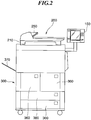
FIG. 2 is a side view showing an appearance of theimage processing apparatus 100 appearing inFIG. 1 . - As shown in the figure, the
reader unit 200 is disposed on theprinter unit 300, and theconsole 150 is disposed on a right side of theprinter unit 300. A discharging tray of the dischargingunit 370 thatprinter unit 300 has is disposed on a left side of theprinter unit 300. Thecontroller unit 110 and thepower supply device 400 appearing inFIG. 1 are housed in theprinter unit 300 appearing inFIG. 2 . - Referring to
FIGS. 1 and2 , thereader unit 200 has a plurality of CCDs (optical reading devices). When the CCDs have different sensitivities, it is determined that pixels constituting an image have different densities when the image on an original is read off. Thus, image data corresponding to reflected light obtained by thereader unit 200 scanning a white board (uniformly white board) by exposing the same to light is sent to thecontroller unit 110 so as to calibrate the sensitivities of the CCDs. - As described above, the
reader unit 200 scans an original by exposing the same to light and inputs reflected light from the original to the CCDs. The CCDs then output electric signals (analog signals) corresponding to the amount of reflected light. Thereader unit 200 converts the electric signals into luminance signals of R, G, and B colors, digitalizes them, and sends the resulting data as image data to thecontroller unit 110. - At the time of reading originals, the originals are placed on a tray provided in the
original feeding unit 250. When a user inputs an instruction to start reading via theconsole 150, thecontroller unit 110 gives an original reading instruction to thereader unit 200. In response to the original reading instruction, thereader unit 200 feeds originals one by one from the tray in theoriginal feeding unit 250. The originals are then fed to thescanner unit 210. - It should be noted that at the time of reading originals, the originals may be placed on a glass surface (not shown), and an exposure unit provided in the scanner unit may be moved along the glass surface to scan the originals.
- As described above, upon receiving image data, the
controller unit 110 controls theprinter unit 300 to perform printing based on image data. Theprinter unit 300 has, for example, a photosensitive drum, and performs image formation (printing) by a so-called electrophotographic process. - It should be noted that as an alternative to the electrophotographic process, the
printer unit 300 may use, for example, a so-called ink-jet process in which ink is jetted from a minute nozzle array to perform printing on a recording sheet. -
FIG. 3 is a block diagram schematically showing a hardware arrangement of thecontroller unit 110 appearing inFIG. 1 . - Referring to
FIG. 3 , thecontroller unit 110 has amain controller 111. Themain controller 111 has aCPU 112, abus controller 113, and various I/F controller circuits (not shown). - The
CPU 112 and thebus controller 113 control the overall operation of thecontroller unit 110. TheCPU 112 operates in accordance with control programs read from aROM 114 via a ROM I/F 115. TheCPU 112 interprets PDL (page description language) code data received from the host computer 10 (FIG. 1 ), and expands the PDL code data into raster image data. Thebus controller 113 controls transfer of data input and output from each I/F, and mediates in the event of a bus conflict and provides control in transferring DMA data. - A
DRAM 116 is connected to themain controller 111 via a DRAM I/F 117. TheDRAM 116 is used as a work area for theCPU 112 and as an area for accumulating image data (including raster image data). - A
Codec 118 compresses raster image data, which is accumulated in theDRAM 116, using MH, MR, MMR, JBIG, JPEG, or the like. Further, theCodec 118 expands code data, which is compressed and accumulated in theDRAM 116, into raster image data. AnSRAM 119 is used as a temporary work area for theCodec 118. - The
Codec 118 is connected to themain controller 111 via an I/F 120, and data transfer between theCodec 118 and theDRAM 116 is controlled by thebus controller 113 and done by DMA transfer. - A
graphic processor 135 carries out processes such as image rotation, zooming, and color space conversion. An external communication I/F controller 121 is connected to themain controller 111 by an I/F 123, and further connected to the LAN 500 (FIG. 1 ), which is a network, by aconnector 122. - An
expansion connector 124 for connecting an expansion board and an I/O control unit 126 are connected to a universal high-speed bus 125. For example, a PCI (Peripheral Component Interconnect) bus or a PCI Express bus is used as the universal high-speed bus 125. - The I/
O control unit 126 is provided with a two-channel asynchronousserial communication controller 127 for transmitting and receiving control commands to and from CPUs provided respectively in thereader unit 200 and theprinter unit 300. Theserial communication controller 127 is connected to a scanner I/F circuit 140 and a printer I/F circuit 145 by an I/O bus 128. - The I/
O control unit 126 is connected to a panel I/F 132 via anLCD controller 131 and also connected to the panel I/F 132 via a key input I/F 130. TheLCD controller 131 produces screen displays on the liquid crystal touch panel provided in the console 150 (FIG. 1 ) via the panel I/F 132. The I/O control unit 126 also receives inputs from hardware keys and touch panel keys, which are provided in theconsole 150, via the key input I/F 130. - An input instruction (input signal) input through operation of the liquid crystal touch panel or the hardware keys is transmitted to the
CPU 112 by the I/O control unit 126. On the liquid crystal touch panel, images corresponding to image data are displayed, and also, functions corresponding to various input operations are displayed. - A real-
time clock module 133 updates and stores date and time managed in the image processing apparatus. The power to the real-time clock module 133 is backed up by abackup battery 134. - An external storage device is connected to a SATA (Serial Advanced Technology Attachment)
connector 161. In the example shown inFIG. 3 , a hard disk (HD) drive 160 which is an external storage device is connected to theSATA connector 161. Image data is stored in anHD 162 by theHD drive 160. The HD drive 160 loads image data recorded in theHD 162. -
Connectors reader unit 200 and theprinter unit 300, respectively. Theconnector 142 is connected to a scanner I/F 140 by an asynchronous serial I/F 143 and a video I/F 144, and theconnector 147 is connected to a printer I/F 145 by an asynchronous serial I/F 148 and a video I/F 149. - The scanner I/
F 140 is connected to themain controller 111 by ascanner bus 141. The scanner I/F 140 carries out predetermined processing on image data received from thereader unit 200. Further, the scanner I/F 140 outputs a control signal, which is generated based on a video control signal from thereader unit 200, to thescanner bus 141. It should be noted that data transfer from thescanner bus 141 to theDRAM 116 is controlled by thebus controller 113. - The printer I/
F 145 is connected to themain controller 111 by aprinter bus 146. The scanner I/F 145 carries out predetermined processing on image data received from themain controller 111 and outputs the resulting image data to theprinter unit 300. Further, the printer I/F 145 outputs a control signal, which is generated based on a video control signal from theprinter unit 300, to theprinter bus 146. - At the time of transferring raster image data expanded on the
DRAM 116 to theprinter unit 300, the transfer is controlled by thebus controller 113. Namely, the raster image data is transferred by DMA to theprinter unit 300 via theprinter bus 146 and the video I/F 149. - A LAN I/
F 502 is connected to thehost computer 10 via theLAN 500. The LAN I/F 502 receives a printing instruction from thehost computer 10. - The power
supply control unit 170 is connected to thepower supply 400 via aconnector 171. Further, the powersupply control unit 170 is connected to themain controller 111. As will be described later, the powersupply control unit 170 performs control to determine whether or not to supply power under the control of themain controller 111. -
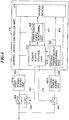
FIG. 4 is a block diagram schematically showing a hardware arrangement associated with a power supply control system in thecontroller unit 110 appearing inFIG. 3 . Although only the powersupply control unit 170 is illustrated as the power supply control system inFIG. 3 , thecontroller unit 110 is additionally provided with first and second powersupply monitoring units FIG. 4 . The power supply (power supply device) 400 appearing inFIG. 1 also has first and secondpower supply units third switches 402 to 404 although they are not shown inFIG. 3 . It should be noted that inFIG. 4 , component elements constituting thecontroller unit 110 arevarious devices 414. - The
first switch 402 is a switch for turning on or off the power to theimage forming apparatus 100. When the user turns on thefirst switch 402, AC power is input from a plug to the firstpower supply unit 401a via thefirst switch 402. - The first
power supply unit 401a converts the AC power to DC power and supplies the DC power asfirst power 405 to thecontroller unit 110. Even when theimage forming apparatus 100 is in a high-speed startup mode and a sleep mode, thefirst power 405 is supplied to thecontroller unit 110. Thefirst power 405 is supplied mainly to the powersupply control unit 170 and is also supplied to a receipt detection circuit (not shown) for detecting receipt from theLAN 500 or a FAX in the sleep mode. In the high-speed startup mode, thefirst power 405 is used as power for holding data in memory (such as DRAM). - The second switches 403 and 404 are controlled to be turned on and off by the power
supply control unit 170. The powersupply control unit 170 provides control to turn on and off thesecond switch 403 by acontrol signal 407. When theimage forming apparatus 100 is normally operating or in the high-speed startup mode or the sleep mode, the powersupply control unit 170 turns on thesecond switch 403. As a result, thefirst power 405 is supplied to thecontroller unit 110 via thesecond switch 403. It should be noted that in the high-speed startup mode, thefirst switch 402 is off, and thesecond switch 403 is on, so that minimum electrical power is supplied to thecontroller unit 110 to start theimage forming apparatus 100 at high speed. - When the
third switch 404 is turned on, the secondpower supply unit 401b converts the AC power to DC power and supplies the DC power assecond power 406 to thecontroller unit 110. The powersupply control unit 170 provides control to turn on and off thethird switch 404 by acontrol signal 415. When theimage forming apparatus 100 is in the high-speed startup mode or the sleep mode, the powersupply control unit 170 turns off thethird switch 404 to stop the input of the AC power to the secondpower supply unit 401b. As a result, the secondpower supply unit 401b stops supplying thesecond power 406 to thecontroller unit 110. - The first power
supply monitoring unit 408 monitors thefirst power 405 and determines whether or not the voltage thereof is normal. Upon determining that the voltage of thefirst power 405 is not normal (for example, when the voltage of thefirst power 405 falls outside a predetermined voltage range), the first powersupply monitoring unit 408 transmits areset signal 411 to the powersupply control unit 170 and thevarious devices 414. When thereset signal 411 is asserted (becomes active), the powersupply control unit 170 is reset to its initial state. Specifically, information stored in the RAM in the powersupply control unit 170 and register information are reset by resetting the powersupply control unit 170. - As shown in the figure, the power
supply control unit 170 supplies areset signal 410 to the first powersupply monitoring unit 408. When the powersupply control unit 170 asserts thereset signal 410, the first powersupply monitoring unit 408 asserts thereset signal 411. As a result, a reset is issued to the powersupply control unit 170 and thevarious devices 414. It should be noted that in response to the input of thereset signal 411, the powersupply control unit 170 determines whether or not thefirst power 405 is being normally supplied. - The second power
supply monitoring unit 409 monitors thesecond power 406 and determines whether or not the voltage thereof is normal. Upon determining that the voltage of thesecond power 406 is not normal (for example, when the voltage of thesecond power 406 falls outside a predetermined voltage range), the second powersupply monitoring unit 409 transmits areset signal 413 to the powersupply control unit 170 and thevarious devices 414. When thereset signal 413 is asserted (becomes active), the powersupply control unit 170 is reset to its initial state. - As shown in the figure, the power
supply control unit 170 supplies areset signal 412 to the second powersupply monitoring unit 409. When the powersupply control unit 170 asserts thereset signal 412, the second powersupply monitoring unit 409 asserts thereset signal 413. As a result, a reset is issued to the powersupply control unit 170 and thevarious devices 414. It should be noted that in response to the input of thereset signal 413, the powersupply control unit 170 determines whether or not thesecond power 406 is being normally supplied. -
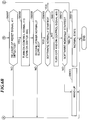
FIGS. 5A and5B are flowcharts useful in explaining a recovery process in a case where hang-up occurs when the image processing apparatus appearing inFIG. 1 is started in the high-speed startup mode. - Referring to
FIGS. 1 ,3 ,4 , and5A and5B , assume now that theimage forming apparatus 100 is set to the high-speed startup mode (step S5001). In the high-speed startup mode, the powersupply control unit 170 turns on thecontrol signal 407, turns off thecontrol signal 415, turns on thesecond switch 402, and turns off thethird switch 404. As a result, only thefirst power 405 is supplied to thecontroller unit 110. Then, electrical power for stopping the supply of thesecond power 406 and executing the high-speed startup mode is supplied to theimage forming apparatus 100. It should be noted that in the high-speed startup mode, thefirst switch 402 is off. - The power
supply control unit 170 monitors thefirst switch 402 to check whether or not thefirst switch 402 is turned on by the user (step S5002). When thefirst switch 402 is not turned on (NO in the step S5002), the powersupply control unit 170 stands by. - When the
first switch 402 is turned on (YES in the step S5002), the powersupply control unit 170 turns on thecontrol signal 415 and turns on the third switch 404 (step S5003). As a result, thesecond power 406 is supplied from the secondpower supply unit 401b to thecontroller unit 110. - Next, the power
supply control unit 170 determines whether or not thesecond power 406 has been normally supplied to the controller unit 110 (step S5004). Here, the second powersupply monitoring unit 409 releases thereset signal 413 when the voltage of thesecond power 406 is normal, and therefore, according to whether or not thereset signal 413 has been released, the powersupply control unit 170 determines whether or not thesecond power 406 has been normally supplied. - When the
second power 406 has not been normally supplied (NO in the step S5004), the powersupply control unit 170 terminates the startup process. - When the
second power 406 has been normally supplied (YES in the step S5004), the powersupply control unit 170 determines whether or not software (program) has been normally started in the CPU 112 (step S5005). For example, the powersupply control unit 170 is equipped with a watchdog timer. According to whether or not a watchdog interrupt to the watchdog timer has been released, the powersupply control unit 170 determines whether or not software has been normally started. - When the software has been normally started (YES in the step S5005), the power
supply control unit 170 brings theimage processing apparatus 100 into its normal state (step S5014) and terminates the startup process. - When software has not been normally started (NO in the step S5005), the power
supply control unit 170 asserts thereset signal 410 and turns off the control signal 415 (step S5006). Due to the reset signal 410 being asserted, thevarious devices 414 and the powersupply control unit 170 are reset to their initial states as described earlier. Due to thecontrol signal 415 being turned off, thethird switch 404 is turned off, and the supply of thesecond power 406 to thecontroller unit 110 is stopped. - In the above described way, the devices to which the
first power 405 is supplied are reset, and the supply of thesecond power 406 is stopped. Thus, even when software hangs up in the high-speed startup mode, thecontroller unit 110 returns to its initial state to do startup from the initial state. - Next, according to the
reset signal 411, the powersupply control unit 170 determines whether or not the first powersupply monitoring unit 408 has canceled the reset (step S5007). Namely, according to whether or not thereset signal 411 has been released, the powersupply control unit 170 determines whether or not thefirst power 405 is being normally supplied to thecontroller unit 110. - When the
reset signal 411 has not been released (NO in the step S5007), the powersupply control unit 170 terminates the startup process. On the other hand, when thereset signal 411 has been released (YES in the step S5007), the powersupply control unit 170 turns on thecontrol signal 415 and turns on the third switch 404 (step S5008). As a result, thesecond power 406 is supplied to thecontroller unit 110. It should be noted that the steps S5006 and S5008 correspond to a first on-off process (or off-on process). - Next, according to the
reset signal 413, the powersupply control unit 170 determines whether or not the second powersupply monitoring unit 409 has canceled the reset (step S5009). Namely, according to whether or not thereset signal 413 has been released, the powersupply control unit 170 determines whether or not thesecond power 406 is being normally supplied to thecontroller unit 110. - When the
reset signal 413 has not been released (NO in the step S5009), the powersupply control unit 170 terminates the startup process. On the other hand, when thereset signal 413 has been released (YES in the step S5009), the powersupply control unit 170 determines again whether or not the software has been normally started (step S5010). When the software has been normally started (YES in the step S5010), the powersupply control unit 170 brings theimage processing apparatus 100 into its normal state (step S5014). - When the software has not been normally started (NO in the step S5010), the power
supply control unit 170 turns off thecontrol signal 415 and turns off the third switch 404 (step S5011). As a result, the supply of thesecond power 406 to thecontroller unit 110 is stopped. Thereafter, in the step S5011, the powersupply control unit 170 turns on thecontrol signal 415 and turns on thethird switch 404. It should be noted that the step S5011 corresponds to a second off-on process. - Thus, when software hangs up, the
second power 406 is turned off and then turned on to restart the software again. As a result, a chance of restoring theimage processing apparatus 100 to its normal state is offered. - Moreover, in the step S5011, assertion of the
reset signal 410 is not done. Because assertion of thereset signal 410 initializes the powersupply control unit 170, assertion of thereset signal 410 in the step S5011 would cause thesecond power 406 to be repeatedly turned on and off when software repeatedly hangs up. Such repeated turning-on and off may cause damage to a normal device. For this reason, assertion of thereset signal 410 is not done in the step S5011. - Next, the power
supply control unit 170 determines whether or not the software has been normally started (step S5012). When the software has been normally started (YES in the step S5012), the powersupply control unit 170 brings theimage processing apparatus 100 into its normal state and terminates the startup process. On the other hand, when the software has not been normally started (NO in the step S5012), the powersupply control unit 170 determines that hang-up has occurred (step S5013) and terminates the startup process. - Thus, even when software hangs up in the high-speed startup mode, a chance of resetting the
controller unit 110 to do startup from an initial state and restoring theimage processing apparatus 100 to its normal state is offered. Then, when the software hangs up again during restart, the second power is turned off and then turned on so that the software can be started again. On this occasion, the powersupply control unit 170 is not reset, and if hang-up of software occurs during the restart, restart is not repeated any more. As a result, damage to devices caused by turning-off and on of the second power can be reduced. -
FIGS. 6A and6B are flowcharts useful in explaining a recovery process in a case where hang-up occurs when the image processing apparatus appearing inFIG. 1 returns from the sleep mode. - Referring to
FIGS. 1 ,3 ,4 ,6A and6B , assume now that theimage processing apparatus 100 is in a sleep state which is a power-saving mode (step S6001). In the sleep state, the powersupply control unit 170 turns on thecontrol signal 407 and turns off thecontrol signal 415. As a result, thesecond switch 403 is turned on, and thethird switch 404 is turned off. Then, only thefirst power 405 is supplied to thecontroller unit 110, and minimum electrical power is supplied to theimage processing apparatus 100. - The power
supply control unit 170 monitors to determine whether or not there is any sleep return factor (step S6002). Here, the sleep return factor is, for example, receipt via FAX or LAN or operation on theconsole 150. - When there is no sleep recovery factor (NO in the step S6002), the power
supply control unit 170 stands by. On the other hand, when there is any sleep recovery factor (YES in the step S6002), the powersupply control unit 170 turns on thecontrol signal 415 and turns on the third switch 404 (step S6003). As a result, thesecond power 406 is supplied to thecontroller unit 110. - Next, the power
supply control unit 170 determines whether or not thesecond power 406 has been normally supplied to the controller unit 110 (step S6004). When thesecond power 406 has not been normally supplied to the controller unit 110 (NO in the step S6004), the powersupply control unit 170 terminates the startup process. - When the
second power 406 has been normally supplied to the controller unit 110 (YES in the step S6004), the powersupply control unit 170 determines whether or not software has been normally started in the CPU 112 (step S6005). When the software has been normally started (YES in the step S6005), the powersupply control unit 170 brings theimage processing apparatus 100 into its normal state (step S6014) and terminates the startup process. - When the software has not been normally started (NO in the step S6005), the power
supply control unit 170 asserts thereset signal 410 and turns off the control signal 415 (step S6006). As a result, thevarious devices 414 and the powersupply control unit 170 are reset to their initial states, and the supply of thesecond power 406 to thecontroller unit 110 is stopped. - Next, according to the
reset signal 411, the powersupply control unit 170 determines whether or not the first powersupply monitoring unit 408 has canceled the reset (step S6007). When thereset signal 411 has not been released (NO in the step S6007), the powersupply control unit 170 terminates the startup process. On the other hand, when thereset signal 411 has been released (YES in the step S6007), the powersupply control unit 170 turns on thecontrol signal 415 and turns on the third switch 404 (step S6008). As a result, thesecond power 406 is supplied to thecontroller unit 110. - Next, according to the
reset signal 413, the powersupply control unit 170 determines whether or not the second powersupply monitoring unit 409 has canceled the reset (step S6009). When thereset signal 413 has not been released (NO in the step S6009), the powersupply control unit 170 terminates the startup process. On the other hand, when thereset signal 413 has been released (YES in the step S6009), the powersupply control unit 170 determines again whether or not the software has been normally started (step S6010). When the software has been normally started (YES in the step S6010), the powersupply control unit 170 brings theimage processing apparatus 100 into its normal state (step S6014). - When the software has not been normally started (NO in the step S6010), the power
supply control unit 170 turns off thecontrol signal 415 and turns off the third switch 404 (step S6011). As a result, the supply of thesecond power 406 to thecontroller unit 110 is stopped. Thereafter, in the step S6011, the powersupply control unit 170 turns on thecontrol signal 415 and turns on thethird switch 404. - Next, the power
supply control unit 170 determines whether or not the software has been normally started (step S6012). When the software has been normally started (YES in the step S6012), the powersupply control unit 170 brings theimage processing apparatus 100 into its normal state and terminates the startup process. On the other hand, when the software has not been normally started (NO in the step S6012), the powersupply control unit 170 determines that software hangs up (step S5013) and terminates the startup process. - In this way, even when software hangs up at the time of return from the sleep mode, a chance of resetting the
controller unit 110 to do startup again from an initial state and restoring theimage processing apparatus 100 to its normal state is offered. Then, when the software hangs up again during the restart, the second power is turned off and then turned on so that the software can be started again. On this occasion, the powersupply control unit 170 is not reset, and when the software hangs up during the restart, restart is not repeated any more. As a result, damage to devices caused by turning-on and off of the second power can be reduced. - Thus, in the embodiment of the present embodiment, even when hang-up occurs, the chance of eliminating a hang-up state and restoring to a normal state without bothering the user can be increased.
- As is clear from the above description, referring to
FIG. 4 , thefirst switch 402, thesecond switch 403, and the firstpower supply unit 401a constitute a first power supply unit. Also, thethird switch 404 and the secondpower supply unit 401b constitute a second power supply unit. Further, the powersupply control unit 170, the first powersupply monitoring unit 408, and the second powersupply monitoring unit 409 act as a determination unit and a control unit. - Aspects of the present invention can also be realized by a computer of a system or apparatus (or devices such as a CPU or MPU) that reads out and executes a program recorded on a memory device to perform the functions of the above-described embodiment(s), and by a method, the steps of which are performed by a computer of a system or apparatus by, for example, reading out and executing a program recorded on a memory device to perform the functions of the above-described embodiment(s). For this purpose, the program is provided to the computer for example via a network or from a recording medium of various types serving as the memory device (e.g., computer-readable medium).
- While the present invention has been described with reference to exemplary embodiments, it is to be understood that the invention is limited by the scope of invention defined in the appended claims.
-
- 100
- Image processing apparatus
- 110
- Control device (controller unit)
- 150
- Console
- 170
- Power supply control unit
- 200
- Image input device (reader unit)
- 300
- Image output device (printer unit)
- 401a, 401b
- Power supply unit
- 402, 403, 404
- Switch
- 408, 409
- Power supply monitoring unit
- 414
- Various devices
Claims (12)
- An information processing apparatus that has a plurality of devices, the information processing apparatus comprising:a controller (111);a power supply control unit (170);a first power supply unit (401a) configured to supply power to the plurality of devices; anda second power supply unit (401b);wherein the power supply control unit (170) is configured to, in a case where a sleep return instruction to return the information processing apparatus from a power saving state is detected in a power saving state in which power is supplied from said first power supply unit (401a) and power is not supplied from said second power supply unit (401b) to said controller (111), provide control so that power is supplied from said second power supply unit (401b) to said controller (111),wherein in a case where software executed by said controller (111) to which power has been supplied is not normally started, said power supply control unit (170) is configured to carry out a first OFF/ON process (S5006 to S5008) in which said power supply control unit (170) provides control so that the devices to which power is supplied by the first power supply unit are reset, stops power supply from said second power supply unit (401b) to said controller (111), and then restarts power supply from said second power supply unit (401b) to said controller (111),characterized in that, in a case where the software executed by said controller (111) to which power has been supplied through the first OFF/ON process is not normally started, said power supply control unit (170) is configured to carry out a second OFF/ON process (S5011) in which said power supply control unit (170) stops power supply from said second power supply unit (401b) to said controller (111) and then restarts power supply from said second power supply unit (401b) to said controller (111) without resetting the devices to which power is supplied by the first power supply device.
- The information processing apparatus according to claim 1, wherein in a case where the software executed by said control unit (111) to which power has been supplied through the second OFF/ON process is not normally started, the software is determined (S5012 to S5013) to hang-up, and startup of the software is terminated.
- The information processing apparatus according to claim 1, wherein said power supply control unit (170) has a timer, and
wherein in a case where the timer is not interrupted by the software within a time period during which the timer continues counting, the software is determined not to be normally started. - The information processing apparatus according to any preceding claim, further comprising an image output unit configured to form an image on a sheet.
- The information processing apparatus according to any preceding claim, further comprising a storage unit and a network interface configured to receive data from an external apparatus,
wherein in the power saving state, power is supplied to said storage unit (116) whereas power is not supplied to said network interface. - The information processing apparatus according to claim 5, wherein said network interface is an interface that receives data from a LAN or an interface that detects receipt from a FAX.
- The information processing apparatus according to any preceding claim, wherein the sleep return instruction is issued in response to a power switch being depressed by a user.
- A control method for an information processing apparatus having a plurality of devices, a controller (111), a first power supply unit (401a) that supplies power to the plurality of devices, a second power supply unit (401b), and a power supply control unit (170) that provides, in a case where a sleep return instruction to return the information processing apparatus from a power saving state is detected in a power saving state in which power is supplied from the first power supply unit (401a) and power is not supplied from the second power supply unit (401b) to the controller (111), control so that power is supplied from the second power supply unit (401b) to the controller, the control method comprising:a first control step (S5006 to S5008) of, in a case where software executed by the controller to which power has been supplied is not normally started, carrying out a first OFF/ON process in which the devices to which power is supplied by the first power supply unit are reset, power supply from the second power supply unit (401b) to the controller is stopped, and then power supply from the second power supply unit (401b) to the controller is restarted,characterized in that the method further comprises a second control step (S5011) of, in a case where the software executed by the controller to which power has been supplied through the first OFF/ON process is not normally started, carrying out a second OFF/ON process in which power supply from the second power supply unit (401b) to the controller is stopped and then power supply from the second power supply unit (401b) to the controller is restarted without resetting the devices to which power is supplied by the first power supply device.
- The control method according to claim 8, wherein in a case where the software executed by the controller to which power has been supplied through the second OFF/ON process is not normally started, the software is determined to hang-up, and startup of the software is terminated.
- The control method according to claim 8 or claim 9, further comprising an image output step of forming an image on a sheet.
- A program which, when run on an information processing apparatus in accordance with any of claims 1 to 7, causes the apparatus to execute a method according to any one of claims 8 to 10.
- A non-transitory computer-readable storage medium storing a program according to claim 11.
Applications Claiming Priority (2)
| Application Number | Priority Date | Filing Date | Title |
|---|---|---|---|
| JP2011128126A JP5858651B2 (en) | 2011-06-08 | 2011-06-08 | Information processing apparatus, control method thereof, and control program |
| PCT/JP2012/064609 WO2012169560A1 (en) | 2011-06-08 | 2012-05-31 | Information processing apparatus that offers chance of eliminating hang-up state, control method therefor, and storage medium |
Publications (3)
| Publication Number | Publication Date |
|---|---|
| EP2719159A1 EP2719159A1 (en) | 2014-04-16 |
| EP2719159A4 EP2719159A4 (en) | 2014-11-26 |
| EP2719159B1 true EP2719159B1 (en) | 2020-03-18 |
Family
ID=47296119
Family Applications (1)
| Application Number | Title | Priority Date | Filing Date |
|---|---|---|---|
| EP12797611.6A Active EP2719159B1 (en) | 2011-06-08 | 2012-05-31 | Information processing apparatus that offers chance of eliminating hang-up state, control method therefor, and storage medium |
Country Status (6)
| Country | Link |
|---|---|
| US (2) | US9158353B2 (en) |
| EP (1) | EP2719159B1 (en) |
| JP (1) | JP5858651B2 (en) |
| KR (1) | KR101583123B1 (en) |
| CN (1) | CN103583034B (en) |
| WO (1) | WO2012169560A1 (en) |
Families Citing this family (15)
| Publication number | Priority date | Publication date | Assignee | Title |
|---|---|---|---|---|
| JP5531005B2 (en) * | 2011-12-26 | 2014-06-25 | 株式会社沖データ | Electronics |
| JP6335438B2 (en) * | 2013-05-17 | 2018-05-30 | キヤノン株式会社 | Switch control device and image forming apparatus |
| US9647453B2 (en) * | 2013-08-02 | 2017-05-09 | Samsung Electronics Co., Ltd. | Dual supply memory |
| JP6218486B2 (en) | 2013-08-05 | 2017-10-25 | キヤノン株式会社 | Printing apparatus, control method therefor, and program |
| US9625495B2 (en) * | 2013-08-22 | 2017-04-18 | Tektronix, Inc. | Isolated probe with digital multimeter or digital voltmeter |
| JP5932738B2 (en) * | 2013-09-02 | 2016-06-08 | キヤノン株式会社 | Electronic device and power control method for control unit of electronic device |
| JP5984790B2 (en) * | 2013-12-18 | 2016-09-06 | キヤノン株式会社 | Information processing apparatus, control method for information processing apparatus, storage medium, and program |
| JP6180450B2 (en) * | 2015-02-02 | 2017-08-16 | キヤノン株式会社 | Control device, control method and program for control device |
| JP6521745B2 (en) * | 2015-05-29 | 2019-05-29 | キヤノン株式会社 | Power supply and image forming apparatus |
| JP6597417B2 (en) | 2016-03-09 | 2019-10-30 | 株式会社リコー | Electronic device, recovery method and program |
| CN206292719U (en) * | 2016-12-05 | 2017-06-30 | 丽宝大数据股份有限公司 | Electronic installation and its power supply circuit |
| EP3438770B1 (en) * | 2017-08-01 | 2020-04-15 | Kverneland Group Mechatronics BV | Method for operating a user terminal of an agricultural machine and agricultural machine |
| JP7105639B2 (en) | 2018-07-05 | 2022-07-25 | 浜松ホトニクス株式会社 | Laser processing equipment |
| JP7242351B2 (en) * | 2019-03-11 | 2023-03-20 | キヤノン株式会社 | Electronic devices that can omit software tampering detection processing at startup |
| TWI768992B (en) * | 2021-06-30 | 2022-06-21 | 創惟科技股份有限公司 | High-speed transimission system, signal redriver and control method of signal redriver |
Family Cites Families (5)
| Publication number | Priority date | Publication date | Assignee | Title |
|---|---|---|---|---|
| JPH08163298A (en) * | 1994-12-09 | 1996-06-21 | Canon Inc | Facsimile equipment |
| TWI243335B (en) * | 2003-09-04 | 2005-11-11 | Htc Corp | Booting method for performing warm boot or cold boot when CPU is down, and its computer system |
| US7774633B1 (en) * | 2006-12-21 | 2010-08-10 | Google Inc. | Controlled power cycling in computing devices |
| JP2010194729A (en) * | 2009-02-23 | 2010-09-09 | Seiko Epson Corp | Electronic device and printing device |
| JP5478971B2 (en) * | 2009-07-27 | 2014-04-23 | キヤノン株式会社 | Image forming apparatus, image forming apparatus control method, and image forming apparatus control program |
-
2011
- 2011-06-08 JP JP2011128126A patent/JP5858651B2/en active Active
-
2012
- 2012-05-31 US US13/575,674 patent/US9158353B2/en active Active
- 2012-05-31 KR KR1020137031745A patent/KR101583123B1/en active IP Right Grant
- 2012-05-31 WO PCT/JP2012/064609 patent/WO2012169560A1/en active Application Filing
- 2012-05-31 CN CN201280027146.4A patent/CN103583034B/en active Active
- 2012-05-31 EP EP12797611.6A patent/EP2719159B1/en active Active
-
2015
- 2015-09-10 US US14/849,796 patent/US10466752B2/en active Active
Non-Patent Citations (1)
| Title |
|---|
| None * |
Also Published As
| Publication number | Publication date |
|---|---|
| US20150378405A1 (en) | 2015-12-31 |
| CN103583034B (en) | 2016-01-27 |
| KR101583123B1 (en) | 2016-01-07 |
| EP2719159A4 (en) | 2014-11-26 |
| JP5858651B2 (en) | 2016-02-10 |
| US20130166926A1 (en) | 2013-06-27 |
| CN103583034A (en) | 2014-02-12 |
| EP2719159A1 (en) | 2014-04-16 |
| WO2012169560A1 (en) | 2012-12-13 |
| KR20140017654A (en) | 2014-02-11 |
| US10466752B2 (en) | 2019-11-05 |
| JP2012257026A (en) | 2012-12-27 |
| US9158353B2 (en) | 2015-10-13 |
Similar Documents
| Publication | Publication Date | Title |
|---|---|---|
| EP2719159B1 (en) | Information processing apparatus that offers chance of eliminating hang-up state, control method therefor, and storage medium | |
| US11307633B2 (en) | Information processing apparatus, control method thereof, and storage medium | |
| KR102006520B1 (en) | Image forming apparatus and control method | |
| US20180032020A1 (en) | Image forming apparatus | |
| CN102883087A (en) | Information processing apparatus and method of controlling launch thereof | |
| US20110141007A1 (en) | Data processing apparatus, data processing system, and display control method for controlling display in data processing apparatus | |
| CN104113651A (en) | Processing Control Apparatus, Image Processing Apparatus, And Processing Control Method | |
| US9900454B2 (en) | Image forming apparatus, job processing control method and non-transitory computer-readable storage medium storing job processing control program | |
| US10732702B2 (en) | Data processing apparatus, method of controlling data processing apparatus, and recording medium | |
| JP7134670B2 (en) | IMAGE FORMING APPARATUS AND CONTROL METHOD FOR IMAGE FORMING APPARATUS | |
| US20240015256A1 (en) | Image forming apparatus, method for controlling image forming apparatus | |
| US9924059B2 (en) | Apparatus having power-saving function, method of processing information, and computer program product | |
| US11330132B2 (en) | Information processing apparatus capable of resetting system, method of controlling same, and storage medium | |
| US20220404893A1 (en) | Image forming apparatus, control method therefor, and storage medium | |
| US9031445B2 (en) | Power saving modes in an image forming apparatus | |
| US11451684B2 (en) | Processor having a plurality of cores and a controller that switches power states based on cores state | |
| US20240103782A1 (en) | Image forming apparatus and control method for image forming apparatus | |
| US11539851B2 (en) | Apparatus for switching a power state among a plurality of power states and method thereof | |
| JP2008022452A (en) | Image forming apparatus | |
| JP5808136B2 (en) | Image forming apparatus, control method thereof, and program |
Legal Events
| Date | Code | Title | Description |
|---|---|---|---|
| PUAI | Public reference made under article 153(3) epc to a published international application that has entered the european phase |
Free format text: ORIGINAL CODE: 0009012 |
|
| 17P | Request for examination filed |
Effective date: 20140108 |
|
| AK | Designated contracting states |
Kind code of ref document: A1 Designated state(s): AL AT BE BG CH CY CZ DE DK EE ES FI FR GB GR HR HU IE IS IT LI LT LU LV MC MK MT NL NO PL PT RO RS SE SI SK SM TR |
|
| DAX | Request for extension of the european patent (deleted) | ||
| A4 | Supplementary search report drawn up and despatched |
Effective date: 20141028 |
|
| RIC1 | Information provided on ipc code assigned before grant |
Ipc: G03G 21/00 20060101ALI20141022BHEP Ipc: G06F 1/00 20060101ALI20141022BHEP Ipc: H04N 1/00 20060101AFI20141022BHEP Ipc: B41J 29/38 20060101ALI20141022BHEP |
|
| STAA | Information on the status of an ep patent application or granted ep patent |
Free format text: STATUS: EXAMINATION IS IN PROGRESS |
|
| 17Q | First examination report despatched |
Effective date: 20171221 |
|
| GRAP | Despatch of communication of intention to grant a patent |
Free format text: ORIGINAL CODE: EPIDOSNIGR1 |
|
| STAA | Information on the status of an ep patent application or granted ep patent |
Free format text: STATUS: GRANT OF PATENT IS INTENDED |
|
| INTG | Intention to grant announced |
Effective date: 20190604 |
|
| GRAJ | Information related to disapproval of communication of intention to grant by the applicant or resumption of examination proceedings by the epo deleted |
Free format text: ORIGINAL CODE: EPIDOSDIGR1 |
|
| STAA | Information on the status of an ep patent application or granted ep patent |
Free format text: STATUS: EXAMINATION IS IN PROGRESS |
|
| GRAP | Despatch of communication of intention to grant a patent |
Free format text: ORIGINAL CODE: EPIDOSNIGR1 |
|
| INTC | Intention to grant announced (deleted) | ||
| STAA | Information on the status of an ep patent application or granted ep patent |
Free format text: STATUS: GRANT OF PATENT IS INTENDED |
|
| INTG | Intention to grant announced |
Effective date: 20191010 |
|
| GRAS | Grant fee paid |
Free format text: ORIGINAL CODE: EPIDOSNIGR3 |
|
| GRAA | (expected) grant |
Free format text: ORIGINAL CODE: 0009210 |
|
| STAA | Information on the status of an ep patent application or granted ep patent |
Free format text: STATUS: THE PATENT HAS BEEN GRANTED |
|
| AK | Designated contracting states |
Kind code of ref document: B1 Designated state(s): AL AT BE BG CH CY CZ DE DK EE ES FI FR GB GR HR HU IE IS IT LI LT LU LV MC MK MT NL NO PL PT RO RS SE SI SK SM TR |
|
| REG | Reference to a national code |
Ref country code: GB Ref legal event code: FG4D |
|
| REG | Reference to a national code |
Ref country code: DE Ref legal event code: R082 Ref document number: 602012068598 Country of ref document: DE Representative=s name: WESER & KOLLEGEN PATENTANWAELTE PARTMBB, DE |
|
| REG | Reference to a national code |
Ref country code: DE Ref legal event code: R096 Ref document number: 602012068598 Country of ref document: DE |
|
| REG | Reference to a national code |
Ref country code: AT Ref legal event code: REF Ref document number: 1247247 Country of ref document: AT Kind code of ref document: T Effective date: 20200415 Ref country code: IE Ref legal event code: FG4D |
|
| PG25 | Lapsed in a contracting state [announced via postgrant information from national office to epo] |
Ref country code: RS Free format text: LAPSE BECAUSE OF FAILURE TO SUBMIT A TRANSLATION OF THE DESCRIPTION OR TO PAY THE FEE WITHIN THE PRESCRIBED TIME-LIMIT Effective date: 20200318 Ref country code: NO Free format text: LAPSE BECAUSE OF FAILURE TO SUBMIT A TRANSLATION OF THE DESCRIPTION OR TO PAY THE FEE WITHIN THE PRESCRIBED TIME-LIMIT Effective date: 20200618 Ref country code: FI Free format text: LAPSE BECAUSE OF FAILURE TO SUBMIT A TRANSLATION OF THE DESCRIPTION OR TO PAY THE FEE WITHIN THE PRESCRIBED TIME-LIMIT Effective date: 20200318 |
|
| REG | Reference to a national code |
Ref country code: NL Ref legal event code: MP Effective date: 20200318 |
|
| PG25 | Lapsed in a contracting state [announced via postgrant information from national office to epo] |
Ref country code: HR Free format text: LAPSE BECAUSE OF FAILURE TO SUBMIT A TRANSLATION OF THE DESCRIPTION OR TO PAY THE FEE WITHIN THE PRESCRIBED TIME-LIMIT Effective date: 20200318 Ref country code: SE Free format text: LAPSE BECAUSE OF FAILURE TO SUBMIT A TRANSLATION OF THE DESCRIPTION OR TO PAY THE FEE WITHIN THE PRESCRIBED TIME-LIMIT Effective date: 20200318 Ref country code: LV Free format text: LAPSE BECAUSE OF FAILURE TO SUBMIT A TRANSLATION OF THE DESCRIPTION OR TO PAY THE FEE WITHIN THE PRESCRIBED TIME-LIMIT Effective date: 20200318 Ref country code: GR Free format text: LAPSE BECAUSE OF FAILURE TO SUBMIT A TRANSLATION OF THE DESCRIPTION OR TO PAY THE FEE WITHIN THE PRESCRIBED TIME-LIMIT Effective date: 20200619 Ref country code: BG Free format text: LAPSE BECAUSE OF FAILURE TO SUBMIT A TRANSLATION OF THE DESCRIPTION OR TO PAY THE FEE WITHIN THE PRESCRIBED TIME-LIMIT Effective date: 20200618 |
|
| REG | Reference to a national code |
Ref country code: LT Ref legal event code: MG4D |
|
| PG25 | Lapsed in a contracting state [announced via postgrant information from national office to epo] |
Ref country code: NL Free format text: LAPSE BECAUSE OF FAILURE TO SUBMIT A TRANSLATION OF THE DESCRIPTION OR TO PAY THE FEE WITHIN THE PRESCRIBED TIME-LIMIT Effective date: 20200318 |
|
| PG25 | Lapsed in a contracting state [announced via postgrant information from national office to epo] |
Ref country code: EE Free format text: LAPSE BECAUSE OF FAILURE TO SUBMIT A TRANSLATION OF THE DESCRIPTION OR TO PAY THE FEE WITHIN THE PRESCRIBED TIME-LIMIT Effective date: 20200318 Ref country code: SM Free format text: LAPSE BECAUSE OF FAILURE TO SUBMIT A TRANSLATION OF THE DESCRIPTION OR TO PAY THE FEE WITHIN THE PRESCRIBED TIME-LIMIT Effective date: 20200318 Ref country code: LT Free format text: LAPSE BECAUSE OF FAILURE TO SUBMIT A TRANSLATION OF THE DESCRIPTION OR TO PAY THE FEE WITHIN THE PRESCRIBED TIME-LIMIT Effective date: 20200318 Ref country code: PT Free format text: LAPSE BECAUSE OF FAILURE TO SUBMIT A TRANSLATION OF THE DESCRIPTION OR TO PAY THE FEE WITHIN THE PRESCRIBED TIME-LIMIT Effective date: 20200812 Ref country code: CZ Free format text: LAPSE BECAUSE OF FAILURE TO SUBMIT A TRANSLATION OF THE DESCRIPTION OR TO PAY THE FEE WITHIN THE PRESCRIBED TIME-LIMIT Effective date: 20200318 Ref country code: RO Free format text: LAPSE BECAUSE OF FAILURE TO SUBMIT A TRANSLATION OF THE DESCRIPTION OR TO PAY THE FEE WITHIN THE PRESCRIBED TIME-LIMIT Effective date: 20200318 Ref country code: IS Free format text: LAPSE BECAUSE OF FAILURE TO SUBMIT A TRANSLATION OF THE DESCRIPTION OR TO PAY THE FEE WITHIN THE PRESCRIBED TIME-LIMIT Effective date: 20200718 Ref country code: SK Free format text: LAPSE BECAUSE OF FAILURE TO SUBMIT A TRANSLATION OF THE DESCRIPTION OR TO PAY THE FEE WITHIN THE PRESCRIBED TIME-LIMIT Effective date: 20200318 |
|
| REG | Reference to a national code |
Ref country code: AT Ref legal event code: MK05 Ref document number: 1247247 Country of ref document: AT Kind code of ref document: T Effective date: 20200318 |
|
| REG | Reference to a national code |
Ref country code: DE Ref legal event code: R097 Ref document number: 602012068598 Country of ref document: DE |
|
| PLBE | No opposition filed within time limit |
Free format text: ORIGINAL CODE: 0009261 |
|
| STAA | Information on the status of an ep patent application or granted ep patent |
Free format text: STATUS: NO OPPOSITION FILED WITHIN TIME LIMIT |
|
| PG25 | Lapsed in a contracting state [announced via postgrant information from national office to epo] |
Ref country code: DK Free format text: LAPSE BECAUSE OF FAILURE TO SUBMIT A TRANSLATION OF THE DESCRIPTION OR TO PAY THE FEE WITHIN THE PRESCRIBED TIME-LIMIT Effective date: 20200318 Ref country code: MC Free format text: LAPSE BECAUSE OF FAILURE TO SUBMIT A TRANSLATION OF THE DESCRIPTION OR TO PAY THE FEE WITHIN THE PRESCRIBED TIME-LIMIT Effective date: 20200318 Ref country code: AT Free format text: LAPSE BECAUSE OF FAILURE TO SUBMIT A TRANSLATION OF THE DESCRIPTION OR TO PAY THE FEE WITHIN THE PRESCRIBED TIME-LIMIT Effective date: 20200318 Ref country code: ES Free format text: LAPSE BECAUSE OF FAILURE TO SUBMIT A TRANSLATION OF THE DESCRIPTION OR TO PAY THE FEE WITHIN THE PRESCRIBED TIME-LIMIT Effective date: 20200318 Ref country code: IT Free format text: LAPSE BECAUSE OF FAILURE TO SUBMIT A TRANSLATION OF THE DESCRIPTION OR TO PAY THE FEE WITHIN THE PRESCRIBED TIME-LIMIT Effective date: 20200318 Ref country code: LI Free format text: LAPSE BECAUSE OF NON-PAYMENT OF DUE FEES Effective date: 20200531 Ref country code: CH Free format text: LAPSE BECAUSE OF NON-PAYMENT OF DUE FEES Effective date: 20200531 |
|
| 26N | No opposition filed |
Effective date: 20201221 |
|
| PG25 | Lapsed in a contracting state [announced via postgrant information from national office to epo] |
Ref country code: PL Free format text: LAPSE BECAUSE OF FAILURE TO SUBMIT A TRANSLATION OF THE DESCRIPTION OR TO PAY THE FEE WITHIN THE PRESCRIBED TIME-LIMIT Effective date: 20200318 |
|
| REG | Reference to a national code |
Ref country code: BE Ref legal event code: MM Effective date: 20200531 |
|
| PG25 | Lapsed in a contracting state [announced via postgrant information from national office to epo] |
Ref country code: LU Free format text: LAPSE BECAUSE OF NON-PAYMENT OF DUE FEES Effective date: 20200531 |
|
| PG25 | Lapsed in a contracting state [announced via postgrant information from national office to epo] |
Ref country code: IE Free format text: LAPSE BECAUSE OF NON-PAYMENT OF DUE FEES Effective date: 20200531 |
|
| PG25 | Lapsed in a contracting state [announced via postgrant information from national office to epo] |
Ref country code: BE Free format text: LAPSE BECAUSE OF NON-PAYMENT OF DUE FEES Effective date: 20200531 Ref country code: SI Free format text: LAPSE BECAUSE OF FAILURE TO SUBMIT A TRANSLATION OF THE DESCRIPTION OR TO PAY THE FEE WITHIN THE PRESCRIBED TIME-LIMIT Effective date: 20200318 |
|
| PG25 | Lapsed in a contracting state [announced via postgrant information from national office to epo] |
Ref country code: TR Free format text: LAPSE BECAUSE OF FAILURE TO SUBMIT A TRANSLATION OF THE DESCRIPTION OR TO PAY THE FEE WITHIN THE PRESCRIBED TIME-LIMIT Effective date: 20200318 Ref country code: MT Free format text: LAPSE BECAUSE OF FAILURE TO SUBMIT A TRANSLATION OF THE DESCRIPTION OR TO PAY THE FEE WITHIN THE PRESCRIBED TIME-LIMIT Effective date: 20200318 Ref country code: CY Free format text: LAPSE BECAUSE OF FAILURE TO SUBMIT A TRANSLATION OF THE DESCRIPTION OR TO PAY THE FEE WITHIN THE PRESCRIBED TIME-LIMIT Effective date: 20200318 |
|
| PG25 | Lapsed in a contracting state [announced via postgrant information from national office to epo] |
Ref country code: MK Free format text: LAPSE BECAUSE OF FAILURE TO SUBMIT A TRANSLATION OF THE DESCRIPTION OR TO PAY THE FEE WITHIN THE PRESCRIBED TIME-LIMIT Effective date: 20200318 Ref country code: AL Free format text: LAPSE BECAUSE OF FAILURE TO SUBMIT A TRANSLATION OF THE DESCRIPTION OR TO PAY THE FEE WITHIN THE PRESCRIBED TIME-LIMIT Effective date: 20200318 |
|
| PGFP | Annual fee paid to national office [announced via postgrant information from national office to epo] |
Ref country code: FR Payment date: 20230420 Year of fee payment: 12 Ref country code: DE Payment date: 20230419 Year of fee payment: 12 |
|
| PGFP | Annual fee paid to national office [announced via postgrant information from national office to epo] |
Ref country code: GB Payment date: 20230420 Year of fee payment: 12 |