EP2718622B1 - A socket, a lighting module and a luminaire - Google Patents
A socket, a lighting module and a luminaire Download PDFInfo
- Publication number
- EP2718622B1 EP2718622B1 EP12726886.0A EP12726886A EP2718622B1 EP 2718622 B1 EP2718622 B1 EP 2718622B1 EP 12726886 A EP12726886 A EP 12726886A EP 2718622 B1 EP2718622 B1 EP 2718622B1
- Authority
- EP
- European Patent Office
- Prior art keywords
- socket
- lighting module
- contact means
- electrical
- socket contact
- Prior art date
- Legal status (The legal status is an assumption and is not a legal conclusion. Google has not performed a legal analysis and makes no representation as to the accuracy of the status listed.)
- Active
Links
- 230000008878 coupling Effects 0.000 description 8
- 238000010168 coupling process Methods 0.000 description 8
- 238000005859 coupling reaction Methods 0.000 description 8
- RYGMFSIKBFXOCR-UHFFFAOYSA-N Copper Chemical compound [Cu] RYGMFSIKBFXOCR-UHFFFAOYSA-N 0.000 description 4
- 229910052802 copper Inorganic materials 0.000 description 4
- 239000010949 copper Substances 0.000 description 4
- 239000000463 material Substances 0.000 description 4
- 238000012546 transfer Methods 0.000 description 4
- OKTJSMMVPCPJKN-UHFFFAOYSA-N Carbon Chemical compound [C] OKTJSMMVPCPJKN-UHFFFAOYSA-N 0.000 description 2
- 230000000712 assembly Effects 0.000 description 2
- 238000000429 assembly Methods 0.000 description 2
- 239000000919 ceramic Substances 0.000 description 2
- 230000001419 dependent effect Effects 0.000 description 2
- 238000013461 design Methods 0.000 description 2
- 230000017525 heat dissipation Effects 0.000 description 2
- 238000009434 installation Methods 0.000 description 2
- 229910000838 Al alloy Inorganic materials 0.000 description 1
- 239000004593 Epoxy Substances 0.000 description 1
- OAICVXFJPJFONN-UHFFFAOYSA-N Phosphorus Chemical compound [P] OAICVXFJPJFONN-UHFFFAOYSA-N 0.000 description 1
- XUIMIQQOPSSXEZ-UHFFFAOYSA-N Silicon Chemical compound [Si] XUIMIQQOPSSXEZ-UHFFFAOYSA-N 0.000 description 1
- 239000000853 adhesive Substances 0.000 description 1
- 230000001070 adhesive effect Effects 0.000 description 1
- 230000004075 alteration Effects 0.000 description 1
- 229910052799 carbon Inorganic materials 0.000 description 1
- 239000003575 carbonaceous material Substances 0.000 description 1
- 238000004891 communication Methods 0.000 description 1
- 239000004020 conductor Substances 0.000 description 1
- 238000011161 development Methods 0.000 description 1
- 229910003460 diamond Inorganic materials 0.000 description 1
- 239000010432 diamond Substances 0.000 description 1
- 239000000428 dust Substances 0.000 description 1
- 239000011888 foil Substances 0.000 description 1
- 229910002804 graphite Inorganic materials 0.000 description 1
- 239000010439 graphite Substances 0.000 description 1
- 238000003780 insertion Methods 0.000 description 1
- 230000037431 insertion Effects 0.000 description 1
- 238000005461 lubrication Methods 0.000 description 1
- 229910052751 metal Inorganic materials 0.000 description 1
- 239000002184 metal Substances 0.000 description 1
- 229910001092 metal group alloy Inorganic materials 0.000 description 1
- 239000000203 mixture Substances 0.000 description 1
- 238000012986 modification Methods 0.000 description 1
- 230000004048 modification Effects 0.000 description 1
- 239000012811 non-conductive material Substances 0.000 description 1
- 239000002245 particle Substances 0.000 description 1
- 230000002093 peripheral effect Effects 0.000 description 1
- 238000007493 shaping process Methods 0.000 description 1
- 229910052710 silicon Inorganic materials 0.000 description 1
- 239000010703 silicon Substances 0.000 description 1
- 229920002379 silicone rubber Polymers 0.000 description 1
- 239000007787 solid Substances 0.000 description 1
Images

Classifications
-
- F—MECHANICAL ENGINEERING; LIGHTING; HEATING; WEAPONS; BLASTING
- F21—LIGHTING
- F21V—FUNCTIONAL FEATURES OR DETAILS OF LIGHTING DEVICES OR SYSTEMS THEREOF; STRUCTURAL COMBINATIONS OF LIGHTING DEVICES WITH OTHER ARTICLES, NOT OTHERWISE PROVIDED FOR
- F21V19/00—Fastening of light sources or lamp holders
- F21V19/0005—Fastening of light sources or lamp holders of sources having contact pins, wires or blades, e.g. pinch sealed lamp
-
- F—MECHANICAL ENGINEERING; LIGHTING; HEATING; WEAPONS; BLASTING
- F21—LIGHTING
- F21K—NON-ELECTRIC LIGHT SOURCES USING LUMINESCENCE; LIGHT SOURCES USING ELECTROCHEMILUMINESCENCE; LIGHT SOURCES USING CHARGES OF COMBUSTIBLE MATERIAL; LIGHT SOURCES USING SEMICONDUCTOR DEVICES AS LIGHT-GENERATING ELEMENTS; LIGHT SOURCES NOT OTHERWISE PROVIDED FOR
- F21K9/00—Light sources using semiconductor devices as light-generating elements, e.g. using light-emitting diodes [LED] or lasers
- F21K9/20—Light sources comprising attachment means
-
- F—MECHANICAL ENGINEERING; LIGHTING; HEATING; WEAPONS; BLASTING
- F21—LIGHTING
- F21V—FUNCTIONAL FEATURES OR DETAILS OF LIGHTING DEVICES OR SYSTEMS THEREOF; STRUCTURAL COMBINATIONS OF LIGHTING DEVICES WITH OTHER ARTICLES, NOT OTHERWISE PROVIDED FOR
- F21V19/00—Fastening of light sources or lamp holders
- F21V19/001—Fastening of light sources or lamp holders the light sources being semiconductors devices, e.g. LEDs
- F21V19/003—Fastening of light source holders, e.g. of circuit boards or substrates holding light sources
-
- F—MECHANICAL ENGINEERING; LIGHTING; HEATING; WEAPONS; BLASTING
- F21—LIGHTING
- F21V—FUNCTIONAL FEATURES OR DETAILS OF LIGHTING DEVICES OR SYSTEMS THEREOF; STRUCTURAL COMBINATIONS OF LIGHTING DEVICES WITH OTHER ARTICLES, NOT OTHERWISE PROVIDED FOR
- F21V19/00—Fastening of light sources or lamp holders
- F21V19/02—Fastening of light sources or lamp holders with provision for adjustment, e.g. for focusing
-
- F—MECHANICAL ENGINEERING; LIGHTING; HEATING; WEAPONS; BLASTING
- F21—LIGHTING
- F21V—FUNCTIONAL FEATURES OR DETAILS OF LIGHTING DEVICES OR SYSTEMS THEREOF; STRUCTURAL COMBINATIONS OF LIGHTING DEVICES WITH OTHER ARTICLES, NOT OTHERWISE PROVIDED FOR
- F21V23/00—Arrangement of electric circuit elements in or on lighting devices
- F21V23/003—Arrangement of electric circuit elements in or on lighting devices the elements being electronics drivers or controllers for operating the light source, e.g. for a LED array
- F21V23/004—Arrangement of electric circuit elements in or on lighting devices the elements being electronics drivers or controllers for operating the light source, e.g. for a LED array arranged on a substrate, e.g. a printed circuit board
- F21V23/005—Arrangement of electric circuit elements in or on lighting devices the elements being electronics drivers or controllers for operating the light source, e.g. for a LED array arranged on a substrate, e.g. a printed circuit board the substrate is supporting also the light source
-
- F—MECHANICAL ENGINEERING; LIGHTING; HEATING; WEAPONS; BLASTING
- F21—LIGHTING
- F21V—FUNCTIONAL FEATURES OR DETAILS OF LIGHTING DEVICES OR SYSTEMS THEREOF; STRUCTURAL COMBINATIONS OF LIGHTING DEVICES WITH OTHER ARTICLES, NOT OTHERWISE PROVIDED FOR
- F21V29/00—Protecting lighting devices from thermal damage; Cooling or heating arrangements specially adapted for lighting devices or systems
- F21V29/50—Cooling arrangements
- F21V29/70—Cooling arrangements characterised by passive heat-dissipating elements, e.g. heat-sinks
- F21V29/74—Cooling arrangements characterised by passive heat-dissipating elements, e.g. heat-sinks with fins or blades
- F21V29/76—Cooling arrangements characterised by passive heat-dissipating elements, e.g. heat-sinks with fins or blades with essentially identical parallel planar fins or blades, e.g. with comb-like cross-section
- F21V29/763—Cooling arrangements characterised by passive heat-dissipating elements, e.g. heat-sinks with fins or blades with essentially identical parallel planar fins or blades, e.g. with comb-like cross-section the planes containing the fins or blades having the direction of the light emitting axis
-
- F—MECHANICAL ENGINEERING; LIGHTING; HEATING; WEAPONS; BLASTING
- F21—LIGHTING
- F21V—FUNCTIONAL FEATURES OR DETAILS OF LIGHTING DEVICES OR SYSTEMS THEREOF; STRUCTURAL COMBINATIONS OF LIGHTING DEVICES WITH OTHER ARTICLES, NOT OTHERWISE PROVIDED FOR
- F21V29/00—Protecting lighting devices from thermal damage; Cooling or heating arrangements specially adapted for lighting devices or systems
- F21V29/50—Cooling arrangements
- F21V29/70—Cooling arrangements characterised by passive heat-dissipating elements, e.g. heat-sinks
- F21V29/74—Cooling arrangements characterised by passive heat-dissipating elements, e.g. heat-sinks with fins or blades
- F21V29/77—Cooling arrangements characterised by passive heat-dissipating elements, e.g. heat-sinks with fins or blades with essentially identical diverging planar fins or blades, e.g. with fan-like or star-like cross-section
- F21V29/773—Cooling arrangements characterised by passive heat-dissipating elements, e.g. heat-sinks with fins or blades with essentially identical diverging planar fins or blades, e.g. with fan-like or star-like cross-section the planes containing the fins or blades having the direction of the light emitting axis
-
- F—MECHANICAL ENGINEERING; LIGHTING; HEATING; WEAPONS; BLASTING
- F21—LIGHTING
- F21Y—INDEXING SCHEME ASSOCIATED WITH SUBCLASSES F21K, F21L, F21S and F21V, RELATING TO THE FORM OR THE KIND OF THE LIGHT SOURCES OR OF THE COLOUR OF THE LIGHT EMITTED
- F21Y2115/00—Light-generating elements of semiconductor light sources
- F21Y2115/10—Light-emitting diodes [LED]
-
- H—ELECTRICITY
- H01—ELECTRIC ELEMENTS
- H01R—ELECTRICALLY-CONDUCTIVE CONNECTIONS; STRUCTURAL ASSOCIATIONS OF A PLURALITY OF MUTUALLY-INSULATED ELECTRICAL CONNECTING ELEMENTS; COUPLING DEVICES; CURRENT COLLECTORS
- H01R33/00—Coupling devices specially adapted for supporting apparatus and having one part acting as a holder providing support and electrical connection via a counterpart which is structurally associated with the apparatus, e.g. lamp holders; Separate parts thereof
- H01R33/945—Holders with built-in electrical component
- H01R33/9456—Holders with built-in electrical component for bayonet type coupling devices
Description
- The invention relates to a socket for receiving a lighting module and to the lighting module and a luminaire comprising the lighting module mounted in the socket.
- Light emitting diodes, LEDs, are employed in a wide range of lighting applications. As LEDs have the advantage of providing a bright light, being reasonably inexpensive and drawing very little power, it is becoming increasingly attractive to use LEDs as an alternative to traditional incandescent lighting. Furthermore, LEDs have a long operational lifetime. As an example, LED lamps may last 100 000 hours which is up to 20 times the operational life of an incandescent lamp.
- However, even though LEDs have a long operational life, individual devices may fail and require early replacement or LED lamps may be replaced for reasons such as upgrading or alternating between different LED lamps. Therefore, serviceable and integrated LED modules with corresponding sockets for general lighting applications are introduced to the market, thereby enabling easy upgrades and replaceability of LED modules. Additionally, a modular system for LED devices provides the possibility to use LED modules from different suppliers.
- Further, LED modules may be replaced and upgraded at the end of their operational life, or earlier, if e.g. a different color temperature is desired, without having to remove the reflector or open the ceiling.
- One kind of LED module is the driver integrated LED module. The LED driver converts 120V (or other voltage) 60 Hz AC power to the low-voltage DC power required by the LEDs and protects them from line-voltage fluctuations.
- The driver integrated LED modules are typically region specific, according to differences in legislation and the driver is designed specifically for the mains supply in a region. Typically 3 regions are defined: North America, Europe/APR and Japan, all having different mains supplies.
- There is a risk involved by having different LED modules designed for different regions. If a region specific LED module is inserted in a holder in another region which has a different mains supply than the LED module is designed for, there is a risk of connecting a module to the wrong mains. This could happen if a module intended for Europe ends up in the US. In the least bad case the LED module just does not work, but in a worse case the LED module will be damaged. To mediate this risk, most prior art lighting products use a keying in the lamp holder and lamp base that differentiates between the different regions, resulting in a different lamp holder for North America, Europe/APR and for Japan. Besides this three-fold lampholder development, the luminary maker also has to keep stock of lamp holders for each region it sells its products in.
-
JP9185978A -
US6271692B1 discloses two pairs of pin sockets wherein each pair is capable of holding a lamp. A ceramic lamp base has two metallic base pins which can mate in either pair of pin sockets. -
WO99/10955A1 - Thus, there is still a need for a luminaire having a socket which can be used for two or more regions.
- It is an object of the present invention to provide an improved lighting assembly and a socket for which can used in more than one region and which reduces the risk of connecting a LED module to the wrong mains supply.
- According to a first aspect of the invention, this and other objects are achieved by a socket for receiving a lighting module comprising a light source, electrical contacting means electrically connected to the light source and a heat spreader in thermal contact with the light source, the socket comprising at least a first set and a second set of socket contact means for providing an electrical interface with the electrical contacting means of the lighting module, wherein the socket is configured to retain the lighting module in a predetermined position in which electrical contact between the electrical contacting means of the lighting module and one of the first and second set of socket contact means is achieved and electrical contact between the electrical contacting means of the lighting module and the other one of the first and second set of socket contact means is prevented.
- By having two or more sets of socket contact means which provide an electrical interface to be connected to a lighting module, the socket may receive different kinds of lighting modules, for example, lighting modules adapted to different voltages. Each set of socket contact means can then be adapted to a specific voltage. For example the first set may be adapted to the voltage system in Europe and the second set to North America or Japan. A socket, which is configured to retain the lighting module in a predetermined position in which electrical contact between the electrical contacting means of the lighting module and one of the first and second set of socket contact means is achieved and electrical contact between the electrical contacting means of the lighting module and the other one of the first and second set of socket contact means is prevented, makes it possible to avoid an electrical connection between the lighting module and the socket if they are not adapted to the same voltage. As an example, only the first set of contact means may be connected to a mains supply with a specific voltage. A lighting module adapted to the same voltage will be arranged in the predetermined position and will make electrical contact. Another lighting module which is adapted to another voltage may be configured differently so it will make contact with the second set of contact means, and hence it will not make electrical contact with the connected mains supply. The connection to the mains supply may be accomplished by the installer. For example the installer may connect the mains supply directly to the set of socket contact means adapted to the same voltage, i.e. both sets of socket contact means are available to connect to the mains supply. As an alternative, only one of the sets of socket contact means is reachable to the installer, i.e. the socket may be pre-connected internally to the set of socket contact means which shall be connected to the mains supply i.e. the installer has only one single option to connecting the mains. The socket is then adapted to a specific voltage. Alternatively, all sets of socket contacts may be connected in parallel.
- In the present context, the electrical contacting means may for example be electrically conductive connector pins for providing power to the light source or electrical contact plates. Furthermore, the electrical contacting means may also comprise contacts for control of and communication with the lighting module. However, the electrical contacting means may also comprise different electrical contacts such as connectors or battery contacts.
- The heat spreader may be a metallic plate providing good thermal conductivity for efficient transfer of heat generated by the light source. However, alternative designs of the heat spreader and other materials compositions providing sufficient thermal conductivity may also be used such as metal alloys, thermal epoxy, diamond or other carbon based materials.
- The light source may advantageously be one or more light emitting diodes (LEDs). LEDs may advantageously be selected over other light sources as they are a cost-efficient alternative as a result of low power consumption and long operational lifetime. Furthermore, as LEDs can be made small the overall size of the lighting assembly may be reduced in comparison with lighting assemblies using incandescent light sources.
- According various embodiments the predetermined position may be defined by the location of one of the first or second set of socket contact means on the socket. If the first or the second set of socket contact means defines the predetermined position there may be no need for a separate means to correctly position the lighting module.
- According to at least one exemplary embodiment the first set and the second set of socket contact means may be electrically connectable to the electrical contacting means of the lighting module through rotation of the lighting module.
- According to at least one exemplary embodiment the second set of socket contact means of the socket may define a second predetermined position of the lighting module in the socket when the first set of contact means defines the first predetermined position. This enables the second set of socket contact means to define a second predetermined position for the lighting module, hence there is no need for a separate means to correctly position the lighting module so that it can make contact with the second set of socket contact means.
- According to at least one exemplary embodiment the socket may comprise a track in which the first set and/or the second set of socket contact means are arranged and at least one of the first set and the second set of socket contact means may be accessible through at least a part of the track. One embodiment may be a socket with two different tracks and each comprises a set of socket contact means. An alternative embodiment may be one track where both sets of socket contact means is arranged into.
- According to at least one exemplary embodiment the track may have a first and a second side track from a common track and the first set of socket contact means may be provided in the first side track and the second set of socket contact means may be provided in the second side track. This way different lighting modules may be arranged in to the same track and then the installer chooses which side track to use, i.e. which set of socket contact means shall be connected. In order to avoid arranging the lighting module in the wrong position, a stop may be incorporated in the socket and/or light module which only admits a lighting module, which is adapted to the same voltage, to electrically connect to the right set of socket contact means. All sets of socket contact means may be connected in parallel thereby preventing the risk of a faulty connection of socket contacts by the installer.
- According to at least one exemplary embodiment the first set and the second set of socket contact means may be reached through rotation in different directions.
- According to at least one exemplary embodiment the first set of socket contact means may comprise a first anode and a first cathode arranged in the socket at a first angular distance and the second set of contact means may comprise the same first anode and a second cathode arranged at a second angular distance and the electrical contacting means of the lighting module may comprise a lighting module anode and a lighting module cathode in a position corresponding to position of the first anode and first or second cathode of the first set or second set of socket contact means in order to make electrical contact with the corresponding first anode and first or second cathode. This allows many different lighting modules to be connected to the socket, hence many different mains voltages, AC as well as DC, which makes the socket more future proof.
- According to at least one exemplary embodiment the first and second set of socket contact means may be slide connectors or spring loaded contacts. These are connectors of the shelf. These slide connectors could also function as retainer springs to improve thermal contact between lighting module and socket, or lighting module and heat spreader, or lighting module and heat sink.
- According to at least one exemplary embodiment the socket has a central axis and the first set and the second set of socket contact means may be electrically connectable with the electrical contacting means of the lighting module through connection in the axial direction of the socket. This enables an easy assembly. For example, two electrically conductive connector pins can be inserted into matching holes in the socket when inserting the light module into the socket in the axial direction of the light module. Another alternative are electrical plate contacts forming the first and the second set of socket contact means which can be placed in contact with plate contacts on the lighting module which during assembly are arranged on top of each other by a linear placement of the lighting module in the socket, i.e. in the axial direction of the socket.
- According to at least one exemplary embodiment the first set of socket contact means may comprise two openings and the second set of socket contact means may comprise two openings, and each set of socket contact means may be adapted to receive two mutually matching electrical contacting means of the lighting module.
- According to at least one exemplary embodiment the electrical contacting means of the lighting module may be electrically conductive connector pins.
- According to at least one exemplary embodiment a lighting module may be received in a socket as described above, the lighting module may comprise a light source, electrical contacting means electrically connected to the light source and a heat spreader in thermal contact with the light source, wherein the electrical contacting means may be arranged to connect with the first or the second set of contact means of the socket when received by the socket in the predetermined position.
- According to at least one exemplary embodiment the electrical contacting means may be electrically conductive connector pins.
- According to at least one exemplary embodiment the electrical contacting means may be electrical contact plates.
- According to at least one exemplary embodiment the light source may be a light emitting diode. LEDs are a cost-efficient as a result of low power consumption and long operational lifetime. Furthermore, as LEDs can be made small the overall size of the lighting assembly may be reduced in comparison with lighting assemblies using incandescent light sources.
- According to at least one exemplary embodiment a luminaire may comprise a lighting module as described above in any of the exemplary embodiments mounted in a socket which is described above in any of the matching exemplary embodiments.
- It is noted that the invention relates to all possible combinations of features recited in the claims.
- This and other aspects of the present invention will now be described in more detail, with reference to the appended drawings showing embodiment(s) of the invention.
-
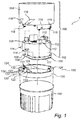
Fig. 1 schematically illustrates a luminaire according to a first embodiment of the present invention with connector pins in a first position. -
Figs. 2a schematically illustrates a luminaire according to the first embodiment of the present invention, with connector pins arranged in a second position. -
Fig. 2b schematically illustrates the second position of the connector pins in cross-section view A-A infig. 2a . -
Fig. 3 schematically illustrates a third position of the connector pins in cross-section view A-A offig. 2a . -
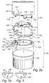
Fig. 4 schematically illustrates a luminaire according to a second embodiment of the present invention. -
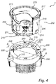
Fig. 5 schematically illustrates the socket ofFig. 4 . -
Fig. 5a schematically illustrates the recess in the socket ofFig. 5 and4 seen from cross-section B-B. -
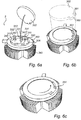
Figs. 6a-6c schematically illustrate a lighting assembly according to a third embodiment of the present invention. -
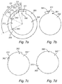
Fig. 7a shows a top view of the socket inFigs. 6a-6c . -
Fig. 7b-7d shows a top view of three different lighting modules inFigs. 6a-6c . -
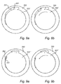
Figs. 8a and 8b schematically illustrate how the socket inFig. 7a interacts and electrically connects with the lighting module ofFig. 7b . -
Figs. 9a and 9b schematically illustrate how the socket inFig. 7a interacts and electrically connects with the lighting module ofFig. 7c . -
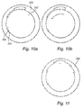
Figs. 10a and 10b schematically illustrate how the socket inFig. 7a interacts and electrically connects with the lighting module ofFig. 7d . -
Fig. 11 shows a second variant socket of the third embodiment of the present invention. - The present invention will now be described more fully hereinafter with reference to the accompanying drawings, in which example embodiments of the invention are shown. This invention may, however, be embodied in many different forms and should not be construed as limited to the embodiments set forth herein; rather, these embodiments are provided for thoroughness and completeness, and fully convey the scope of the invention to the skilled person.
-
Fig. 1 schematically illustrates aluminaire 1, according to a first embodiment, comprising alighting assembly 100. Thelighting assembly 100 comprising alighting module 102 and aconnector 104 configured to be connected to asocket 150 having a collar shapedportion 120. The collar shaped portion is arranged to aheat sink 140. Thelighting module 102 comprises aLED light source 106, two electrical contacting means 108', 108" in the form of electrically conductive connector pins 108', 108" connected to theLED 106 and aheat spreader 110 which is in thermal contact with theLED 106. In the present example, two electrically conductive connector pins 108', 108" are configured to provide contact to a power source. The two pins are arranged next to each other. A layer of thermal interface material (TIM) 111 is arranged on theheat spreader 110 on the side facing theheat sink 140. Theheat sink 140 is provided with fins for efficient transfer of heat from theheat sink 140 to the surrounding air. - The
lighting module 102 is further equipped withelectronics 112 for controlling theLED 106. Theconnector 104 is shaped as an essentially cylindrical housing encompassing thelighting module 102. The guiding pins 114 arranged on the outside of an essentially cylindrical portion of thelighting module 102 are configured to fit in corresponding guidingslots 116 arranged on the inside of theconnector 104. Alternatively, the guiding pins may be arranged on the connector in which case the guiding slots are arranged in the lighting module. The guiding pins 114 and guidingslots 116 keep the lighting module and the connector together and they also allow theconnector 104 to rotate and move in an axial direction in relation thelighting module 102. Only as much rotation and axial movement as is needed for installation of thelighting assembly 100 into thesocket 150 is allowed. Furthermore, spring means, here in the form ofleaf springs 118, are arranged on a lower portion of theconnector 104. The connector is also equipped withfastening pins 119 forming the male portion of a bayonet coupling for fastening thelighting assembly 100 to thesocket 150. It is however realized that thelighting module 102 can be arranged to thesocket 150 in any other suitable way, for example by using screws. - Moreover, the collar shaped
portion 120 of thesocket 150 is equipped with three receiving contact means 122', 122" and 122''' in the form of three openings, a first opening 122', asecond opening 122" and a third opening 122''' for axially receiving the connector pins 108', 108" and they are arranged to each other in a triangular shape, where each opening is arranged in the corner of the triangle. The openings are not limited to this arrangement, they may for example be arranged in a row or any other suitable position. The first opening 122' and thesecond opening 122" form a first set of socket contact means 131 and the first opening 122'and thethird opening 122"' form a second set of socket contact means 132 and the second opening 122'and the third opening 122'" form a third set of socket contact means 133. - The three sets 131, 132, 133 of contact means provide three different electrical interfaces which may work with three different lighting modules. Each set of socket contact means can be connected to a mains supply (not shown), through for example wires (not shown). Each set of socket contact means 131, 132, 133 works at a predetermined voltage and set of socket contact means is adapted to a different voltage. For example, the
first set 131 may be adapted to the mains supply in North America, thesecond set 132 may be adapted for Europe and the third set of socket contact means 133 may be adapted to the mains supply in Japan. When mounting thesocket 150, for example to a ceiling in North America the installer may connect the mains supply to the first set of socket contact means 131 and when arranging thelighting module 102 suitable for North America, shown inFig. 1 , its twoconnector pins 108', 108" will only fit into the twoopenings 122', 122", which forms the first set of socket contact means 131. These connector pins 108', 108" are also adapted to the same voltage as the mains supply and a safe and adequate electrical connection is made. -
Fig. 2a and 2b show how, for example, a European adapted lighting module 102' may have it pins arranged in such a way that, when fitted into thesocket 150, the pins 108'and 108'" will only connect to the second set of socket contact means 132 i.e. the first and thethird opening 122', 122"'.Fig. 2b shows the area of thepins 108', 108"' on thelighting module 102 when viewing the electrical contact area of thelighting module 102 at the cross-section A-A inFig. 2a . -
Fig. 3 shows the area of thepins 108", 108"' on thelighting module 102, when thelighting module 102, for example, is adapted for Japan when viewing thelighting module 102 at the cross-section A-A inFig. 2a . The pins are now arranged differently. - When the
lighting module 102 has it pins arranged like this, thepins 108", 108"' will only connect to the third set of socket contact means 133 inFig. 1 and2a i.e. the second and thethird opening 122", 122"' when thelighting module 102 is fitted into thesocket 150, - If the exemplified European lighting module 102' as configured in
Fig. 2a, 2b is arranged to thesocket 150, which is electrically connected to the mains supply as described above, i.e. the first set of socket contact means 131 which is, exemplified as adapted and connected to the mains supply in North America, thepins 108', 108" of the European lighting module will not connect to the first set of socket contact means 131, which are connected to the mains supply. In this case no electrical connection is made, because thepins 108', 108" will be arranged into theopenings 122', 122"', i.e. the second set of socket contact means 132, where no electrical contact to the mains supply is made. This also applies the other way around, i.e. in the case that a socket is arranged for Europe and the European set of connector means are connected to the European mains supply and a Japanese or a North American lighting module is arranged to the European connected socket. - Further, the socket has L-shaped
recesses 124 forming the female portion of a bayonet coupling for fastening thelighting assembly 100 to thesocket 150. Thesocket 150 also has features in the form ofopenings 126 for screwing the collar shapedportion 120 of thesocket 150 to theheat sink 140. - The mounting of the
lighting assembly 100 into thesocket 150 can be done in the following way. First, thelighting assembly 100 is axially inserted into thesocket 150. The form of the opening in collar shapedportion 120 of thesocket 150 corresponds to the form of theheat spreader 110 and the connector pins 108 are thereby correctly aligned to be axially inserted into thereceiving contacting means 122. Simultaneously, the fastening pins 119 are axially inserted into the L-shapedrecesses 124, together forming a bayonet coupling. Next, a rotational motion of theconnector 104 in relation to thesocket 150 and in relation to thelighting module 102 closes the bayonet coupling, simultaneously moving theconnector 104 in the axial direction in relation to thesocket 150 and the lighting module towards theheat sink 140. As theconnector 104 is moved towards theheat sink 140, theleaf springs 118 in theconnector 104 apply a force on theheat spreader 110 in the axial direction, thereby pressing theheat spreader 110 against theheat sink 140 forming a good thermal contact. Since theheat spreader 110 is fixed to thelighting module 102, the lighting module is also moved in the axial direction in relation to the connector. This combined rotational and axial movement of the lighting module in relation to the connector is controlled by the guidingslots 116 in the connector and the corresponding guiding pins 114 in the lighting module. As said above it is realized that thelighting module 102 can be arranged to thesocket 150 in any other suitable way, for example by using screws. -
Fig. 4 schematically illustrates a second embodiment of aluminaire 2, comprising asocket 250 and alighting module 202. The socket, here referred to as alamp holder 250, is formed as a receiving part of a bayonet coupling enclosing acircular opening 206 for receiving thelighting module 202. Thelamp holder 250 is here mounted to theheat sink 240 withscrews 260. Thus, as thelighting module 202 is connected to thelamp holder 250, a thermal interface of the lighting module, provided at the bottom of the lighting module, is in direct contact with theheat sink 240, thereby enabling heat dissipation from thelighting module 202 to theheat sink 240. - The
lighting module 202, here referred to as anLED module 202, comprises a cylindrical housing comprising abottom surface 216, aside wall 210, and atop surface 219. The top surface is here aphosphor disc 219 for allowing light from the LED module to escape. The housing contains a plurality light emittingdevices 209, here beingLEDs 209 arranged on a printedcircuit board 211. The number and type of LEDs may vary depending on the application, but is in this embodiment nine high power LEDs, each having a power of about 1 W. TheLED module 202 may also include acavity 213 for beam shaping, and agrip ring 217 which a user may grab when the LED module is connected/disconnected to thelamp holder 250. - Further, a
bottom portion 230 of theLED module 202 forms acylindrical plug 230, here referred to as lamp cap, adapted to be received by thelamp holder 250. A set of externalradial protrusions 214 arranged on theside wall 210 form fastening pins 214 for mechanically connecting theLED module 202 to thelamp holder 250. Here, there are three fastening pins, but the number of fastening pins may vary. - The
bottom portion 230 is also provided with anelectrical interface 215, i.e. electrical contact means, which enables theLED module 202 to be electrically connected to an external power supply (AC or DC). The electrical interface is here in the form of twoelectrical contacts 215. Theelectrical contacts 215, which in this embodiment are arranged next to each other, extends radially from thehousing 210. Arranging theelectrical contacts 215 next to each other (rather than on opposite sides of the housing) saves space on the printed circuit board, and reduces electromagnetic interference (EMI). As illustrated inFig. 4 , theelectrical contacts 215 may preferably be made directly onto the printedcircuit board 211, thereby avoiding further components and costs. - The
bottom portion 230 is provided with athermal interface 216 for thermally connecting the LED module to theheat sink 240. Thethermal interface 216 of the LED module is here a flat copper plate arranged to form the bottom of theLED module 202. Other materials having a high thermal conductivity such as carbon, an aluminum alloy, thermally conductive plastic or ceramics may also be used for thethermal interface 216. Theflat copper plate 216 is in thermal contact with theLEDs 209, e.g. by means of a series of thermal vias provided in the printedcircuit board 211. The area of thethermal interface 216 is designed to enable sufficient heat to be dissipated from theLED module 202 to theheat sink 240. In the illustrated example, thethermal interface 216 constitutes essentially the entire bottom surface of theLED module 202. -
Fig. 5 schematically illustrates a more detailed view of thelamp holder 250 inFig. 4 . Thelamp holder 250 comprises a firstannular member 203 and a secondannular member 204, both of which can be made of thermally non-conductive material such as plastic. The firstannular member 203 is firmly mounted to theheat sink 240 byscrews 208, whereas the secondannular member 204 is resiliently supported in relation to the firstannular member 203. The resilient support is in this embodiment achieved by a set ofsprings 290, here being four coil springs, arranged between the first 203 and second 204 annular members. However, the number and type of springs may vary. For example, a leaf spring may be used. Furthermore, the resilient support may also be achieved using other types of elastic elements. For example, instead of using a spring, a cylinder made of silicon rubber may be used. - The second
annular member 204, here being a plastic ring, is provided with atrack 212 in which afirst set 231 and a second 232 set of socket contact means are arranged in and the first set and the second set of socket contact means are reached through rotation of the lighting module when the lighting module is guided in the track to a mounted position. Thetrack 212 has a first and a second side track from an insertion position and they are in arranged in opposite directions and in the end of the first side track is the first set of socket contact means provided and the second set of socket contact means is provided in the end of the second side track. The first and second set of socket contact means are in the shape of two contact plates.Fig. 5a shows the track at the cross-section view B-B inFig. 5 . Thetrack 212 can be seen as an upside-down T-shapedrecess 212 on the inner circumferential side of the socket. The track/recess 212 is arranged to receive theelectrical contacts 215 of theLED module 102 and to guide the lighting module in a rotational movement to the electrical connecting positions. The contact plates can be made from copper, or some other electrically conductive material, and can be electrically connected to a power supply circuitry in a luminaire. - The upside-down T-shaped recess i.e. the
track 212 has its opening facing thelighting module 202 connecting side inFig. 4 , such that theelectrical contact 215 of thelighting module 202 inFig. 4 can be introduced into the upside-down T-shaped recess/track in an axial direction of the socket. Thetrack 212 is provided with a first 241 and a second 242 side track which are arranged in opposite positions from each other on the opposite side of the opening, i.e. the common opening/insert 240, giving thetrack 212 its upside-down T-shaped shape. The first set of socket contact means 231 is provided in the end of thefirst side track 241 and thesecond set 232 of socket contact means is provided in the end of thesecond side track 242. - Each set of socket contact means 231, 232 is adapted to a predetermined voltage and they are both adapted to different voltages. For example, the
first set 231 may be adapted to the mains supply in North America and thesecond set 232 may be adapted to the mains supply for Europe or Japan. When mounting thesocket 250, for example, to a ceiling in North America the installer connects the mains supply to the first set of socket contact means 231. When thelighting module 202, i.e. the LED module for America, is arranged in thesocket 250 itselectrical contacts 215 will make electrical contact with the first set of socket contact means 231, which is connected to the mains supply. If thelighting module 202 is twisted so that it connects the second set of socket contact means 232, there will be no electrical contact since the second set of socket contact means 232 is not electrically connected to the mains supply. Thesocket 250 and therecess 212 may be so designed that, dependent on where it shall be used, it has a twist stop so that alighting module 202 cannot be twisted to the set of socket contact means which is not suited for that area. That is, a socket to be used in North American may have a of twist stop which allows lighting modules for North America only be twisted to the right set of socket contact means, i.e. here the first set of socket contact means. As an alternative, the recess/track 212 or thelighting module 202 could be designed in such a way that, if a European adapted lighting module is arranged into a North American connected socket, thelighting module 202 may be twisted in both ways, but if twisted to the first set of socket contact means, which is adapted to North American mains supply, the electrical contacts of the European will not make contact with the contacts in the first set of socket contact means. In this embodiment the first and the second set of socket contact means determine the positions, i.e. predetermined positions, of the lighting module in which electrical contact between the electrical contacting means of the lighting module and one of the first and second set of socket contact means is achieved. - The
LED module 202 is connected to thelamp holder 250 by the fastening pins 214 are introduced into upside-down shaped recesses 220 (seefig. 4 ), whereas theelectrical contacts 215 of the LED module will fit into the upside-down T-shapedrecess 212. Next, theLED module 202 is twisted clockwise or counter clockwise. As theLED module 202 is twisted, the fastening pins 214 presses the secondannular member 204 upwards, thereby compressing thesprings 290. As the fastening pins 214 pass theshoulders 270, the user will feel the LED module click into place, and theshoulders 270 will lock the fastening pins 214 in their end positions In this position, the electrical contact plates in the lamp holder will be in contact with theelectrical contacts 215 of the LED module. It can be noted that the fastening pins are sufficiently high for the second annular member not to be in contact with theheat sink 240. Thus, the secondannular member 204 will press the fastening pins 214 in the direction of theheat sink 240, whereby the thermal interface 216 (i.e. the bottom surface) of the LED module is pressed against the upper surface 226 of theheat sink 240. - The
springs 290 may be configured such that a predetermined pressure is applied to the fastening pins 214, whereby the predetermined pressure can also be achieved between thethermal interface 216 of the LED module and theheat sink 240. - It can further be noted that as the
opening 206 in thelamp holder 250 is a through-hole, there is a direct contact between thethermal interface 216 of the LED module and theheat sink 240, i.e. thelamp holder 202 is not in the thermal path. - To facilitate the twist-movement, the
thermal interface 216 of the LED module may comprise a layer with a first adhesive side attached to the copper plate of the LED module and a second side, facing the heat sink, that provides ample lubrication for the twist movement. Examples of such a layer are a metal film with silicon adhesion, such as Laird T-Flex 320H, or a graphite foil, such as GrafTech HI-710. Furthermore, by using an interface layer, such as the Laird T-Flex 320H, which is compressible (in thickness), a thermal interface is achieved that is robust against scratches, dust and other particles. According to an alternative embodiment, such a layer may be provided at the heat sink. - Further, to ensure good thermal transfer between the
thermal interface 216 of the LED module and theheat sink 240, adequate pressure should preferably be applied. Most thermal interface materials require about 10 PSI (pound-force per square inch) to provide good thermal transfer, but Laird T-Flex 320H can be used with a lower pressure (about 2.5 PSI). A lower pressure may be advantageous because the user needs to generate the torque, when twisting in the module, that creates this pressure. The desired pressure can be achieved, for example, by adjusting the number of springs in the lamp holder and their spring constants. It should be realized that thelighting module 102 can be arranged to thesocket 250 in any other suitable way, for example by using screws. -
Fig. 6a shows a third embodiment of theluminaire 3. It discloses asocket 350 for connecting alighting module 302 to aheat sink 340. Thelighting module 302 is illustrated by only showing the bottom part of it and the electrical interface. Thelighting module 302 may be designed in a similar way as the lighting module described and shown inFig. 4 . Thesocket 350 is formed as a receiving part of three bayonet couplings enclosing acircular opening 306 for receiving thelighting module 302. Thesocket 350 may be mounted to theheat sink 340 by screws (not shown). Thus, as thelighting module 302 is connected to thesocket 250, a thermal interface of the lighting module (provided at the bottom of the lighting module) is in direct contact with theheat sink 340, thereby enabling heat dissipation from thelighting module 302 to theheat sink 340. The socket may be designed in a similar way as the socket described in the second embodiment except that the electrical interface between thelighting module 302 and thesocket 350 is different and the fastening of thelighting module 302 to thesocket 350 may be made in a different way. Thesocket 350 has three L-shapedconnected recesses bayonet coupling different lighting module 302, which each may be adapted to a different voltage, for example to be operable with the North American, European or Japanese means supply. Within the area of the first L-shapedrecess 311 at the bottom part of the opening on the socket is ananode 300 and afirst cathode 341 arranged at a first angular distance (see D1 infig. 7a ) from each other. Asecond cathode 342 is arranged at the area of the second L-shapedrecess 312, at the bottom part of the opening on the socket, and athird cathode 343 is arranged at the area of the third L-shapedrecess 312, at the bottom part of the opening on the socket. All three cathodes work together with thecommon anode 300. The second 342 and thethird cathode 343 are arranged at a second and a third angular distance (see D2 resp. D3 infig. 7a ) from thecommon anode 300. Thefirst cathode 341 and thecommon anode 300 forms the first set of socket contact means 331. Thesecond cathode 342 and thecommon anode 300 forms the second set of socket contact means 332. Thethird cathode 343 and thecommon anode 300 forms the third set of socket contact means 333. The first set of socket contact means 331 is adapted to a first voltage, for example to the mains supply in North America. The second set of socket contact means 332 is adapted to a second voltage, for example to the mains supply in European. The third set of socket contact means 333 is adapted to a third voltage, for example to the mains supply in Japan. -
Fig. 6b shows the shape of the lighting module 302 (dotted lines) with amale part 360 protruding radially out from the lighting module to fit into the firstfemale recess 311 in thesocket 350. It will make electrical contact with the first set of socket contact means 331. Themale part 360 has a cross section which is L-shaped and fits into the L-shaped female recess, and may work as a bayonet connection together. The lighting module is fitted into theopening 306 of the socket and the male part is arranged in the female opening in an axial direction of the socket. The width of the L-shaped male part is smaller than the opening i.e. insert of the female L-shaped part in order to arrange the male part into the female part. When arranged in thesocket 350 thelighting module 302 is turned in the direction of the arrow inFig. 6c until it hits with its side 361 a stop created bywall 351 of the L-shapedrecess 311. Themale part 360 has on its underside an anode and a cathode arranged (not shown) which will, when it is arranged in the correct position, i.e. when turned until it hits the stop, be in electrical contact with theanode 300 and thefirst cathode 341 of the first set of socket contact means 331. The anode and cathode may be accomplished by coding pins and when the lighting module is arranged in correct position the coding pins will press against electronic contact plates forming the anode and cathodes in the socket (not shown). -
Fig. 7a shows thesocket 350 from above with theopening 306 and the openings of the female L-shapedrecess socket 350. It shows thecommon anode 300 arranged in the area of the first shapedrecess 311. It also shows the threedifferent cathodes stop -
Fig. 7b-c shows three different shapes of the lighting module. -
Fig. 7b shows a lighting module 302' which will fit into the first L-shapedrecess 311 and make contact and it has ananode 381 and acathode 371. Theanode 381 when arranged in correct position in thesocket 350 be arranged in contact with in thecommon anode 300, and thecathode 371 will be in electrical contact with thefirst cathode 341. Thewall 361 of the male L- shaped part will hitwall 351 when the lighting module is arranged in a correct position and lie adjacent to each other in an assembled luminaire. This is shown inFig. 8a and 8b. Fig. 8a shows how the lighting module 302' is arranged in thesocket 350 before rotating the lighting module 302' andFig. 8b shows the situation when the lighting module 302' and thesocket 350 make electrical contact. This lighting module 302' is adapted to the North American system. -
Fig. 7c shows alighting module 302 "which will fit into the second L-shapedrecess 312 and which has ananode 382 and acathode 372. Theanode 382 when arranged in correct position in thesocket 350 will be arranged in electrical contact with thecommon anode 300 and thecathode 372 will be in electrical contact with thesecond cathode 342. Thewall 362 of the male L- shaped part will hitwall 352 when the lighting module is arranged in a correct position and will be adjacent to each other in an assembled luminaire. This is shown inFig. 9a and 9b. Fig.9 shows how thelighting module 302" is arranged in thesocket 350 before rotating thelighting module 302" andFig. 9b shows the situation when they make electrical contact. Thislighting module 302" is adapted to the European system. -
Fig. 7d shows alighting module 302"'which will fit into the third L-shapedrecess 313 and it has ananode 383 and acathode 373. Theanode 383 when arranged in correct position in thesocket 350 will be arranged in electrical contact with thecommon anode 300 and thecathode 373 will be in electrical contact with thethird cathode 342. Thewall 363 of the male L- shaped part will hitwall 353 when the lighting module is arranged in a correct position and will be adjacent to each other in an assembled luminaire. This is shown inFig. 10a and 10b. Fig. 10a shows how it is arranged in the socket before rotating the lighting module 302'" andFig. 10b shows the situation when they make electrical contact. This lighting module 302'" is adapted to the Japanese system. It is however realized that theselighting modules 302', 302", 302'" infig7b-d may be adapted to other mains supplied than mentioned. For example the one described inFig. 7b may adapt for the Japanese system or the European system etc. - If a
socket 350 is installed in North America and the first set of socket contact means 331 is connected to the mains supply in North America and aEuropean light module 302"as shown inFig. 7c is arranged into thesocket 350, no electrical contact will be made since thesecond cathode 342 in the socket will not be connected to the mains supply. Electrical contact will only be made if a lighting module adapted to the North American market is arranged into the socket, which will have its anode and cathode at a corresponding position as the anode and cathode in the socket. The anodes and the cathodes in the socket and/or the lighting module may be realized by slide connectors or spring loaded contacts and/or coding pins and/or electrical plates. This system creates closed electrical circuits, however it might be possible to design the system so that it creates open circuits. Then, however, all the circuits have to be opened except the desired one. Further, it is possible to connect all sets of socket contacts means in parallel so as to prevent any mistakes in connections during assembly and installation. -
Fig. 11 shows asocket 350 which has more than three female bayonet connections each with its own cathode and, together with the common anode, forming a fourth set of socket contact means and a fifth set of socket contact means in order to connect more than three different light modules. - The person skilled in the art realizes that the present invention by no means is limited to the preferred embodiments described above. On the contrary, many alterations, modifications and variations are possible within the scope of the appended claims. For example, other solid state light sources than LEDs may be used, e.g. lasers or laser diodes. Further, the connector may be used for any electrical interface, being an AC mains voltage, a low voltage AC voltage or a DC voltage. Additionally, the mechanical connection may be made in other ways such as by using screw threads.
- Additionally, variations to the disclosed embodiments can be understood and effected by the skilled person in practicing the claimed invention, from a study of the drawings, the disclosure, and the appended claims. In the claims, the word "comprising" does not exclude other elements or steps, and the indefinite article "a" or "an" does not exclude a plurality. The mere fact that certain measures are recited in mutually different dependent claims does not indicate that a combination of these measured cannot be used to advantage.
Claims (10)
- A socket (150, 250, 350) for receiving a lighting module (102, 102', 202, 302', 302", 302'"), the lighting module comprising a light source (106, 209), electrical contacting means (108', 108", 108"', 215, 381; 371, 382; 372, 383; 373) electrically connected to the light source (106, 209) and a heat spreader (140, 240, 340) in thermal contact with the light source (106, 209),
the socket (150, 250, 350) comprising at least a first set (131, 231, 331) and a second set (132, 232, 332) of socket contact means for providing an electrical interface with the electrical contacting means (108', 108", 108"', 215, 381; 371, 382; 372, 383; 373) ofthe lighting module (102, 102', 202, 302', 302", 302'"),
wherein the socket (150, 250, 350) is configured to retain the lighting module (102, 102', 202, 302', 302", 302'") in a predetermined position in which electrical contact between the electrical contacting means (108', 108", 108"', 215, 381; 371, 382; 372, 383; 373) ofthe lighting module (102, 102', 202, 302', 302", 302'") and one ofthe first (131, 231, 331) and second set (132, 232, 332) of socket contact means is achieved and electrical contact between the electrical contacting means (108', 108", 108"', 215, 381; 371, 382; 372, 383; 373) of the lighting module (102, 102', 202, 302', 302", 302'") and the other one of the first (131, 231, 331) and second set (132, 232, 332) of socket contact means is prevented, and
wherein the socket (250, 350) comprises a tracks (212) in which the first set (231, 331) and/or the second set (232, 332) of socket contact means are arranged and at least one of the first set (231, 331) and the second set (232, 332) of socket contact means being accessible through at least a part of the track (212). - The socket (150, 250, 350) according to claim 1, wherein the predetermined position is defined by the location of one of the first set (131, 231, 331) or the second set (132, 232, 332) of socket contact means on the socket (150, 250, 350).
- The socket (250, 350) according to claim 1 or 2, wherein the first set (231, 331) and the second set (232, 332) of socket contact means are electrically connectable to the electrical contacting means (215, 381; 371, 382; 372, 383; 373) of the lighting module (202, 302', 302", 302"') through rotation of the lighting module (202, 302', 302", 302'").
- The socket (250, 350) according to any one of claims 1-3, wherein the second set (232, 332) of socket contact means of the socket (250, 350) defines a second predetermined position of the lighting module in the socket (250, 350) when the first set of contact means (231, 331) defines the first predetermined position.
- The socket (250, 350) according to any one of claims 1-4, wherein each set of socket contact means is adapted to predetermined and different voltages.
- The socket (250) according to claim 5, wherein the track (212) has a first (241) and a second (242) side track from a common track (240) and the first set of socket contact means (231) is provided in the first side track (241) and the second set (232) of socket contact means is provided in the second side track (242).
- The socket (250) according to any one of claims 1-6 wherein first set (231) and the second set (232) of socket contact means are reached through rotation of the lighting module in different directions.
- The socket (250, 350) according to claims 7 wherein the socket comprises a twist stop.
- The socket (350) according to any one of claims 1-4, wherein the first set of socket contact means (331) comprises a first anode (300) and a first cathode (341) arranged in the socket (350) at a first angular distance (D1) and the second set (332) of contact means comprises the same first anode (300) and a second cathode (342) arranged at a second angular distance (D2) and the electrical contacting means (381; 371, 382; 372, 383; 373) of the lighting module (302', 302", 302"') comprises a lighting module anode (381, 382) and a lighting module cathode (371, 372) in a position corresponding to the position of the first anode (300) and first or second cathode (341, 342) of the first set (331) or second set (332) of socket contact means in order to make electrical contact with the corresponding first anode and first or second cathode.
- The socket (250, 350) according to any of claims 1-9 wherein the first set (231, 331) and second set (232, 332) of socket contact means are slide connectors or spring loaded contacts or electrical contact plates.
Priority Applications (1)
| Application Number | Priority Date | Filing Date | Title |
|---|---|---|---|
| EP12726886.0A EP2718622B1 (en) | 2011-06-06 | 2012-05-30 | A socket, a lighting module and a luminaire |
Applications Claiming Priority (3)
| Application Number | Priority Date | Filing Date | Title |
|---|---|---|---|
| EP11168753 | 2011-06-06 | ||
| PCT/IB2012/052697 WO2012168831A2 (en) | 2011-06-06 | 2012-05-30 | A socket, a lighting module and a luminaire |
| EP12726886.0A EP2718622B1 (en) | 2011-06-06 | 2012-05-30 | A socket, a lighting module and a luminaire |
Publications (2)
| Publication Number | Publication Date |
|---|---|
| EP2718622A2 EP2718622A2 (en) | 2014-04-16 |
| EP2718622B1 true EP2718622B1 (en) | 2016-05-04 |
Family
ID=46246130
Family Applications (1)
| Application Number | Title | Priority Date | Filing Date |
|---|---|---|---|
| EP12726886.0A Active EP2718622B1 (en) | 2011-06-06 | 2012-05-30 | A socket, a lighting module and a luminaire |
Country Status (5)
| Country | Link |
|---|---|
| US (1) | US9146023B2 (en) |
| EP (1) | EP2718622B1 (en) |
| JP (1) | JP6010116B2 (en) |
| CN (1) | CN103765095B (en) |
| WO (1) | WO2012168831A2 (en) |
Families Citing this family (15)
| Publication number | Priority date | Publication date | Assignee | Title |
|---|---|---|---|---|
| CN105451615B (en) * | 2013-08-05 | 2018-02-16 | 夏普株式会社 | Stirring vane, agitating device, beverage making device and mixing part |
| CN104421874B (en) * | 2013-08-28 | 2018-11-27 | 海洋王(东莞)照明科技有限公司 | Lamp adapter assembly and lamps and lanterns with the lamp adapter assembly |
| CN105281163B (en) * | 2014-06-06 | 2017-11-07 | 欧普照明股份有限公司 | A kind of adapter assembly |
| CN105276535A (en) * | 2014-06-06 | 2016-01-27 | 欧普照明股份有限公司 | Switching component |
| US20160178181A1 (en) * | 2014-11-14 | 2016-06-23 | Bridgelux, Inc. | Ism architecture adapted for variable optical configurations |
| US10352541B2 (en) | 2015-01-30 | 2019-07-16 | Signify Holding B.V. | Integrated smart module architecture |
| AT516979B1 (en) * | 2015-03-30 | 2017-03-15 | Brunner Marco | illuminant |
| WO2016176564A1 (en) * | 2015-04-29 | 2016-11-03 | Michael Archuleta | Magnetic coupling for bulbs and sockets |
| KR102417439B1 (en) | 2015-10-20 | 2022-07-07 | 쑤저우 레킨 세미컨덕터 컴퍼니 리미티드 | Illumination apparatus |
| CN106949443B (en) * | 2017-04-25 | 2019-04-02 | 湖南粤港模科实业有限公司 | A kind of modularized circuit, LED light and modularization lamps and lanterns |
| DE102017111485A1 (en) | 2017-05-24 | 2018-11-29 | Christian Engelmann | Luminaire with replaceable LED module |
| TWI695554B (en) * | 2018-08-07 | 2020-06-01 | 台達電子工業股份有限公司 | Power adapter assembly |
| US10559916B1 (en) * | 2018-08-07 | 2020-02-11 | Delta Electronics, Inc. | Adapter assembly |
| US10989397B2 (en) * | 2019-07-01 | 2021-04-27 | Green Creative Ltd | Track-light fixture |
| CN113300162B (en) * | 2021-05-11 | 2022-06-24 | 公牛集团股份有限公司 | Hot plug module and power distribution socket |
Family Cites Families (24)
| Publication number | Priority date | Publication date | Assignee | Title |
|---|---|---|---|---|
| JPS54182574U (en) * | 1978-06-15 | 1979-12-24 | ||
| US5378158A (en) | 1994-01-21 | 1995-01-03 | Delco Electronics Corporation | Light emitting diode and socket assembly |
| JP3336180B2 (en) * | 1995-12-28 | 2002-10-21 | 松下電工株式会社 | Lamp socket |
| US5803590A (en) * | 1996-03-08 | 1998-09-08 | Thomas & Betts Corporation | Roadway luminaire |
| US6036522A (en) | 1997-02-21 | 2000-03-14 | Holzer; Walter | Shockproof and touch-safe lamp holder and adapter system for lamps |
| US6638088B1 (en) * | 1997-04-23 | 2003-10-28 | Anthony, Inc. | Lighting circuit, lighting system method and apparatus, socket assembly, lamp insulator assembly and components thereof |
| US6271629B1 (en) * | 2000-01-25 | 2001-08-07 | Vincent Mario Pace | Modular system for movie set lighting |
| US6746260B2 (en) | 2002-07-31 | 2004-06-08 | Maytag Corporation | Universal lamp holder assembly for an appliance |
| US7300173B2 (en) * | 2004-04-08 | 2007-11-27 | Technology Assessment Group, Inc. | Replacement illumination device for a miniature flashlight bulb |
| JP2005166618A (en) * | 2003-11-28 | 2005-06-23 | Hitachi Lighting Ltd | Fluorescent lamp lighting apparatus |
| US7540761B2 (en) * | 2007-05-01 | 2009-06-02 | Tyco Electronics Corporation | LED connector assembly with heat sink |
| US7677766B2 (en) * | 2007-05-07 | 2010-03-16 | Lsi Industries, Inc. | LED lamp device and method to retrofit a lighting fixture |
| US7407418B1 (en) * | 2007-10-01 | 2008-08-05 | Whil Harlan | Adapter for connecting a low voltage light bulb to a standard electrical light socket |
| DE102008008809B3 (en) * | 2008-02-12 | 2009-04-30 | Bjb Gmbh & Co.Kg | Lamp i.e. compact fluorescent lamp, arrangement device for illuminating space, has lamp holder inserted into lamp socket when illumination specified by base key does not exceed maximally permissible illumination defined by socket key |
| DE102008012472A1 (en) * | 2008-03-04 | 2009-09-10 | Bjb Gmbh & Co.Kg | Pedestal socket system for lamps |
| JP5370642B2 (en) * | 2008-11-28 | 2013-12-18 | 東芝ライテック株式会社 | lighting equipment |
| CA2765816C (en) * | 2009-06-17 | 2018-02-13 | Koninklijke Philips Electronics N.V. | A connector for connecting a component to a heat sink |
| EP2284440A1 (en) | 2009-08-14 | 2011-02-16 | Koninklijke Philips Electronics N.V. | A connector for connecting a component to a heat sink |
| US8573807B2 (en) | 2009-06-26 | 2013-11-05 | Intel Corporation | Light devices having controllable light emitting elements |
| WO2011011323A1 (en) * | 2009-07-21 | 2011-01-27 | Cooper Technologies Company | Interfacing a light emitting diode (led) module to a heat sink assembly, a light reflector and electrical circuits |
| CN101839416B (en) | 2010-02-02 | 2011-12-14 | 鸿富锦精密工业(深圳)有限公司 | Lighting system, general lamp holder thereof and LED lamp thereof |
| JP2013528902A (en) * | 2010-04-26 | 2013-07-11 | シカト・インコーポレイテッド | Mounting tool for LED-based lighting module to fixed member |
| AT12549U1 (en) * | 2010-09-20 | 2012-07-15 | Tridonic Connection Technology Gmbh & Co Kg | DEVICE FOR MOUNTING AND CONTACTING A LIGHTING MEANS AND / OR A LIGHTING MODULE, AND LIGHT |
| US8702437B2 (en) * | 2011-03-24 | 2014-04-22 | Correlated Magnetics Research, Llc | Electrical adapter system |
-
2012
- 2012-05-30 JP JP2014514179A patent/JP6010116B2/en active Active
- 2012-05-30 WO PCT/IB2012/052697 patent/WO2012168831A2/en active Application Filing
- 2012-05-30 US US14/119,473 patent/US9146023B2/en active Active
- 2012-05-30 CN CN201280027453.2A patent/CN103765095B/en active Active
- 2012-05-30 EP EP12726886.0A patent/EP2718622B1/en active Active
Also Published As
| Publication number | Publication date |
|---|---|
| US20140092582A1 (en) | 2014-04-03 |
| CN103765095B (en) | 2016-12-14 |
| EP2718622A2 (en) | 2014-04-16 |
| WO2012168831A2 (en) | 2012-12-13 |
| WO2012168831A3 (en) | 2013-02-28 |
| JP2014519172A (en) | 2014-08-07 |
| CN103765095A (en) | 2014-04-30 |
| JP6010116B2 (en) | 2016-10-19 |
| US9146023B2 (en) | 2015-09-29 |
Similar Documents
| Publication | Publication Date | Title |
|---|---|---|
| EP2718622B1 (en) | A socket, a lighting module and a luminaire | |
| RU2571194C2 (en) | Connector for connection of component to heat sink | |
| JP5688295B2 (en) | Lighting fixture assembly and LED assembly | |
| EP2284440A1 (en) | A connector for connecting a component to a heat sink | |
| EP2087555B1 (en) | Led socket and replaceable led assemblies | |
| EP2257730B1 (en) | Integrated led driver for led socket | |
| US20140204572A1 (en) | System for Adapting an Existing Florescent Light Fixture with an LED Luminaire | |
| KR101403194B1 (en) | Lighting device | |
| EP2699841B1 (en) | Lighting assembly and socket | |
| US20110115373A1 (en) | Modular led lighting device | |
| US20160025277A1 (en) | System for adapting an existing fluorescent light fixture with an LED luminaire |
Legal Events
| Date | Code | Title | Description |
|---|---|---|---|
| PUAI | Public reference made under article 153(3) epc to a published international application that has entered the european phase |
Free format text: ORIGINAL CODE: 0009012 |
|
| 17P | Request for examination filed |
Effective date: 20140107 |
|
| AK | Designated contracting states |
Kind code of ref document: A2 Designated state(s): AL AT BE BG CH CY CZ DE DK EE ES FI FR GB GR HR HU IE IS IT LI LT LU LV MC MK MT NL NO PL PT RO RS SE SI SK SM TR |
|
| DAX | Request for extension of the european patent (deleted) | ||
| 17Q | First examination report despatched |
Effective date: 20150317 |
|
| GRAP | Despatch of communication of intention to grant a patent |
Free format text: ORIGINAL CODE: EPIDOSNIGR1 |
|
| INTG | Intention to grant announced |
Effective date: 20151126 |
|
| GRAS | Grant fee paid |
Free format text: ORIGINAL CODE: EPIDOSNIGR3 |
|
| GRAA | (expected) grant |
Free format text: ORIGINAL CODE: 0009210 |
|
| RIC1 | Information provided on ipc code assigned before grant |
Ipc: F21Y 115/10 20160101ALN20160323BHEP Ipc: F21V 23/06 20060101ALI20160323BHEP Ipc: F21K 9/20 20160101ALI20160323BHEP Ipc: F21V 19/00 20060101AFI20160323BHEP |
|
| AK | Designated contracting states |
Kind code of ref document: B1 Designated state(s): AL AT BE BG CH CY CZ DE DK EE ES FI FR GB GR HR HU IE IS IT LI LT LU LV MC MK MT NL NO PL PT RO RS SE SI SK SM TR |
|
| REG | Reference to a national code |
Ref country code: GB Ref legal event code: FG4D |
|
| REG | Reference to a national code |
Ref country code: CH Ref legal event code: EP |
|
| REG | Reference to a national code |
Ref country code: AT Ref legal event code: REF Ref document number: 797243 Country of ref document: AT Kind code of ref document: T Effective date: 20160515 |
|
| REG | Reference to a national code |
Ref country code: IE Ref legal event code: FG4D |
|
| REG | Reference to a national code |
Ref country code: DE Ref legal event code: R096 Ref document number: 602012018062 Country of ref document: DE |
|
| REG | Reference to a national code |
Ref country code: FR Ref legal event code: PLFP Year of fee payment: 5 |
|
| RAP2 | Party data changed (patent owner data changed or rights of a patent transferred) |
Owner name: PHILIPS LIGHTING HOLDING B.V. |
|
| REG | Reference to a national code |
Ref country code: NL Ref legal event code: MP Effective date: 20160504 |
|
| REG | Reference to a national code |
Ref country code: LT Ref legal event code: MG4D |
|
| PG25 | Lapsed in a contracting state [announced via postgrant information from national office to epo] |
Ref country code: LT Free format text: LAPSE BECAUSE OF FAILURE TO SUBMIT A TRANSLATION OF THE DESCRIPTION OR TO PAY THE FEE WITHIN THE PRESCRIBED TIME-LIMIT Effective date: 20160504 Ref country code: NL Free format text: LAPSE BECAUSE OF FAILURE TO SUBMIT A TRANSLATION OF THE DESCRIPTION OR TO PAY THE FEE WITHIN THE PRESCRIBED TIME-LIMIT Effective date: 20160504 Ref country code: NO Free format text: LAPSE BECAUSE OF FAILURE TO SUBMIT A TRANSLATION OF THE DESCRIPTION OR TO PAY THE FEE WITHIN THE PRESCRIBED TIME-LIMIT Effective date: 20160804 Ref country code: FI Free format text: LAPSE BECAUSE OF FAILURE TO SUBMIT A TRANSLATION OF THE DESCRIPTION OR TO PAY THE FEE WITHIN THE PRESCRIBED TIME-LIMIT Effective date: 20160504 |
|
| REG | Reference to a national code |
Ref country code: GB Ref legal event code: 732E Free format text: REGISTERED BETWEEN 20161006 AND 20161012 |
|
| REG | Reference to a national code |
Ref country code: AT Ref legal event code: MK05 Ref document number: 797243 Country of ref document: AT Kind code of ref document: T Effective date: 20160504 |
|
| PG25 | Lapsed in a contracting state [announced via postgrant information from national office to epo] |
Ref country code: HR Free format text: LAPSE BECAUSE OF FAILURE TO SUBMIT A TRANSLATION OF THE DESCRIPTION OR TO PAY THE FEE WITHIN THE PRESCRIBED TIME-LIMIT Effective date: 20160504 Ref country code: RS Free format text: LAPSE BECAUSE OF FAILURE TO SUBMIT A TRANSLATION OF THE DESCRIPTION OR TO PAY THE FEE WITHIN THE PRESCRIBED TIME-LIMIT Effective date: 20160504 Ref country code: SE Free format text: LAPSE BECAUSE OF FAILURE TO SUBMIT A TRANSLATION OF THE DESCRIPTION OR TO PAY THE FEE WITHIN THE PRESCRIBED TIME-LIMIT Effective date: 20160504 Ref country code: ES Free format text: LAPSE BECAUSE OF FAILURE TO SUBMIT A TRANSLATION OF THE DESCRIPTION OR TO PAY THE FEE WITHIN THE PRESCRIBED TIME-LIMIT Effective date: 20160504 Ref country code: GR Free format text: LAPSE BECAUSE OF FAILURE TO SUBMIT A TRANSLATION OF THE DESCRIPTION OR TO PAY THE FEE WITHIN THE PRESCRIBED TIME-LIMIT Effective date: 20160805 Ref country code: PT Free format text: LAPSE BECAUSE OF FAILURE TO SUBMIT A TRANSLATION OF THE DESCRIPTION OR TO PAY THE FEE WITHIN THE PRESCRIBED TIME-LIMIT Effective date: 20160905 Ref country code: LV Free format text: LAPSE BECAUSE OF FAILURE TO SUBMIT A TRANSLATION OF THE DESCRIPTION OR TO PAY THE FEE WITHIN THE PRESCRIBED TIME-LIMIT Effective date: 20160504 |
|
| PG25 | Lapsed in a contracting state [announced via postgrant information from national office to epo] |
Ref country code: BE Free format text: LAPSE BECAUSE OF NON-PAYMENT OF DUE FEES Effective date: 20160531 Ref country code: IT Free format text: LAPSE BECAUSE OF FAILURE TO SUBMIT A TRANSLATION OF THE DESCRIPTION OR TO PAY THE FEE WITHIN THE PRESCRIBED TIME-LIMIT Effective date: 20160504 |
|
| REG | Reference to a national code |
Ref country code: CH Ref legal event code: PL |
|
| PG25 | Lapsed in a contracting state [announced via postgrant information from national office to epo] |
Ref country code: SK Free format text: LAPSE BECAUSE OF FAILURE TO SUBMIT A TRANSLATION OF THE DESCRIPTION OR TO PAY THE FEE WITHIN THE PRESCRIBED TIME-LIMIT Effective date: 20160504 Ref country code: DK Free format text: LAPSE BECAUSE OF FAILURE TO SUBMIT A TRANSLATION OF THE DESCRIPTION OR TO PAY THE FEE WITHIN THE PRESCRIBED TIME-LIMIT Effective date: 20160504 Ref country code: RO Free format text: LAPSE BECAUSE OF FAILURE TO SUBMIT A TRANSLATION OF THE DESCRIPTION OR TO PAY THE FEE WITHIN THE PRESCRIBED TIME-LIMIT Effective date: 20160504 Ref country code: EE Free format text: LAPSE BECAUSE OF FAILURE TO SUBMIT A TRANSLATION OF THE DESCRIPTION OR TO PAY THE FEE WITHIN THE PRESCRIBED TIME-LIMIT Effective date: 20160504 Ref country code: LI Free format text: LAPSE BECAUSE OF NON-PAYMENT OF DUE FEES Effective date: 20160531 Ref country code: CZ Free format text: LAPSE BECAUSE OF FAILURE TO SUBMIT A TRANSLATION OF THE DESCRIPTION OR TO PAY THE FEE WITHIN THE PRESCRIBED TIME-LIMIT Effective date: 20160504 Ref country code: CH Free format text: LAPSE BECAUSE OF NON-PAYMENT OF DUE FEES Effective date: 20160531 |
|
| REG | Reference to a national code |
Ref country code: DE Ref legal event code: R097 Ref document number: 602012018062 Country of ref document: DE |
|
| REG | Reference to a national code |
Ref country code: DE Ref legal event code: R081 Ref document number: 602012018062 Country of ref document: DE Owner name: SIGNIFY HOLDING B.V., NL Free format text: FORMER OWNER: KONINKLIJKE PHILIPS N.V., EINDHOVEN, NL Ref country code: DE Ref legal event code: R082 Ref document number: 602012018062 Country of ref document: DE Representative=s name: MEISSNER BOLTE PATENTANWAELTE RECHTSANWAELTE P, DE Ref country code: DE Ref legal event code: R081 Ref document number: 602012018062 Country of ref document: DE Owner name: PHILIPS LIGHTING HOLDING B.V., NL Free format text: FORMER OWNER: KONINKLIJKE PHILIPS N.V., EINDHOVEN, NL |
|
| REG | Reference to a national code |
Ref country code: IE Ref legal event code: MM4A |
|
| PG25 | Lapsed in a contracting state [announced via postgrant information from national office to epo] |
Ref country code: PL Free format text: LAPSE BECAUSE OF FAILURE TO SUBMIT A TRANSLATION OF THE DESCRIPTION OR TO PAY THE FEE WITHIN THE PRESCRIBED TIME-LIMIT Effective date: 20160504 Ref country code: SM Free format text: LAPSE BECAUSE OF FAILURE TO SUBMIT A TRANSLATION OF THE DESCRIPTION OR TO PAY THE FEE WITHIN THE PRESCRIBED TIME-LIMIT Effective date: 20160504 Ref country code: BE Free format text: LAPSE BECAUSE OF FAILURE TO SUBMIT A TRANSLATION OF THE DESCRIPTION OR TO PAY THE FEE WITHIN THE PRESCRIBED TIME-LIMIT Effective date: 20160504 Ref country code: AT Free format text: LAPSE BECAUSE OF FAILURE TO SUBMIT A TRANSLATION OF THE DESCRIPTION OR TO PAY THE FEE WITHIN THE PRESCRIBED TIME-LIMIT Effective date: 20160504 |
|
| PLBE | No opposition filed within time limit |
Free format text: ORIGINAL CODE: 0009261 |
|
| STAA | Information on the status of an ep patent application or granted ep patent |
Free format text: STATUS: NO OPPOSITION FILED WITHIN TIME LIMIT |
|
| PG25 | Lapsed in a contracting state [announced via postgrant information from national office to epo] |
Ref country code: MC Free format text: LAPSE BECAUSE OF FAILURE TO SUBMIT A TRANSLATION OF THE DESCRIPTION OR TO PAY THE FEE WITHIN THE PRESCRIBED TIME-LIMIT Effective date: 20160504 |
|
| 26N | No opposition filed |
Effective date: 20170207 |
|
| REG | Reference to a national code |
Ref country code: FR Ref legal event code: PLFP Year of fee payment: 6 |
|
| PG25 | Lapsed in a contracting state [announced via postgrant information from national office to epo] |
Ref country code: SI Free format text: LAPSE BECAUSE OF FAILURE TO SUBMIT A TRANSLATION OF THE DESCRIPTION OR TO PAY THE FEE WITHIN THE PRESCRIBED TIME-LIMIT Effective date: 20160504 Ref country code: IE Free format text: LAPSE BECAUSE OF NON-PAYMENT OF DUE FEES Effective date: 20160530 |
|
| REG | Reference to a national code |
Ref country code: FR Ref legal event code: PLFP Year of fee payment: 7 |
|
| PG25 | Lapsed in a contracting state [announced via postgrant information from national office to epo] |
Ref country code: CY Free format text: LAPSE BECAUSE OF FAILURE TO SUBMIT A TRANSLATION OF THE DESCRIPTION OR TO PAY THE FEE WITHIN THE PRESCRIBED TIME-LIMIT Effective date: 20160504 Ref country code: HU Free format text: LAPSE BECAUSE OF FAILURE TO SUBMIT A TRANSLATION OF THE DESCRIPTION OR TO PAY THE FEE WITHIN THE PRESCRIBED TIME-LIMIT; INVALID AB INITIO Effective date: 20120530 |
|
| PG25 | Lapsed in a contracting state [announced via postgrant information from national office to epo] |
Ref country code: IS Free format text: LAPSE BECAUSE OF FAILURE TO SUBMIT A TRANSLATION OF THE DESCRIPTION OR TO PAY THE FEE WITHIN THE PRESCRIBED TIME-LIMIT Effective date: 20160504 Ref country code: MK Free format text: LAPSE BECAUSE OF FAILURE TO SUBMIT A TRANSLATION OF THE DESCRIPTION OR TO PAY THE FEE WITHIN THE PRESCRIBED TIME-LIMIT Effective date: 20160504 Ref country code: LU Free format text: LAPSE BECAUSE OF NON-PAYMENT OF DUE FEES Effective date: 20160530 Ref country code: TR Free format text: LAPSE BECAUSE OF FAILURE TO SUBMIT A TRANSLATION OF THE DESCRIPTION OR TO PAY THE FEE WITHIN THE PRESCRIBED TIME-LIMIT Effective date: 20160504 Ref country code: MT Free format text: LAPSE BECAUSE OF NON-PAYMENT OF DUE FEES Effective date: 20160531 |
|
| PG25 | Lapsed in a contracting state [announced via postgrant information from national office to epo] |
Ref country code: BG Free format text: LAPSE BECAUSE OF FAILURE TO SUBMIT A TRANSLATION OF THE DESCRIPTION OR TO PAY THE FEE WITHIN THE PRESCRIBED TIME-LIMIT Effective date: 20160504 |
|
| PG25 | Lapsed in a contracting state [announced via postgrant information from national office to epo] |
Ref country code: AL Free format text: LAPSE BECAUSE OF FAILURE TO SUBMIT A TRANSLATION OF THE DESCRIPTION OR TO PAY THE FEE WITHIN THE PRESCRIBED TIME-LIMIT Effective date: 20160504 |
|
| REG | Reference to a national code |
Ref country code: DE Ref legal event code: R082 Ref document number: 602012018062 Country of ref document: DE Representative=s name: MEISSNER BOLTE PATENTANWAELTE RECHTSANWAELTE P, DE Ref country code: DE Ref legal event code: R081 Ref document number: 602012018062 Country of ref document: DE Owner name: SIGNIFY HOLDING B.V., NL Free format text: FORMER OWNER: PHILIPS LIGHTING HOLDING B.V., EINDHOVEN, NL |
|
| P01 | Opt-out of the competence of the unified patent court (upc) registered |
Effective date: 20230421 |
|
| PGFP | Annual fee paid to national office [announced via postgrant information from national office to epo] |
Ref country code: FR Payment date: 20230523 Year of fee payment: 12 |
|
| PGFP | Annual fee paid to national office [announced via postgrant information from national office to epo] |
Ref country code: GB Payment date: 20230523 Year of fee payment: 12 |
|
| PGFP | Annual fee paid to national office [announced via postgrant information from national office to epo] |
Ref country code: DE Payment date: 20230726 Year of fee payment: 12 |