EP2717957B1 - Arterial cannula for cardiac surgery - Google Patents
Arterial cannula for cardiac surgery Download PDFInfo
- Publication number
- EP2717957B1 EP2717957B1 EP12732558.7A EP12732558A EP2717957B1 EP 2717957 B1 EP2717957 B1 EP 2717957B1 EP 12732558 A EP12732558 A EP 12732558A EP 2717957 B1 EP2717957 B1 EP 2717957B1
- Authority
- EP
- European Patent Office
- Prior art keywords
- cannula
- stopper
- pledget
- introducer
- assembly
- Prior art date
- Legal status (The legal status is an assumption and is not a legal conclusion. Google has not performed a legal analysis and makes no representation as to the accuracy of the status listed.)
- Not-in-force
Links
- 238000007675 cardiac surgery Methods 0.000 title claims description 7
- 238000000034 method Methods 0.000 claims description 8
- 230000013011 mating Effects 0.000 claims description 2
- 239000008280 blood Substances 0.000 description 10
- 210000004369 blood Anatomy 0.000 description 10
- 238000013459 approach Methods 0.000 description 8
- 239000000463 material Substances 0.000 description 5
- 210000000709 aorta Anatomy 0.000 description 4
- 238000013461 design Methods 0.000 description 3
- 238000012800 visualization Methods 0.000 description 3
- 208000002847 Surgical Wound Diseases 0.000 description 2
- 230000000747 cardiac effect Effects 0.000 description 2
- 210000000038 chest Anatomy 0.000 description 2
- 238000003780 insertion Methods 0.000 description 2
- 230000037431 insertion Effects 0.000 description 2
- 239000004033 plastic Substances 0.000 description 2
- 210000001562 sternum Anatomy 0.000 description 2
- 238000001356 surgical procedure Methods 0.000 description 2
- 210000002376 aorta thoracic Anatomy 0.000 description 1
- 210000005249 arterial vasculature Anatomy 0.000 description 1
- 210000001367 artery Anatomy 0.000 description 1
- 210000004204 blood vessel Anatomy 0.000 description 1
- 238000006243 chemical reaction Methods 0.000 description 1
- 238000007796 conventional method Methods 0.000 description 1
- 238000012937 correction Methods 0.000 description 1
- 230000002439 hemostatic effect Effects 0.000 description 1
- 238000002324 minimally invasive surgery Methods 0.000 description 1
- 238000012978 minimally invasive surgical procedure Methods 0.000 description 1
- 230000007170 pathology Effects 0.000 description 1
- 230000035515 penetration Effects 0.000 description 1
- 239000004417 polycarbonate Substances 0.000 description 1
- 229920000515 polycarbonate Polymers 0.000 description 1
- 230000006641 stabilisation Effects 0.000 description 1
- 238000011105 stabilization Methods 0.000 description 1
- 210000002268 wool Anatomy 0.000 description 1
Images


Classifications
-
- A—HUMAN NECESSITIES
- A61—MEDICAL OR VETERINARY SCIENCE; HYGIENE
- A61B—DIAGNOSIS; SURGERY; IDENTIFICATION
- A61B17/00—Surgical instruments, devices or methods
- A61B17/34—Trocars; Puncturing needles
- A61B17/3415—Trocars; Puncturing needles for introducing tubes or catheters, e.g. gastrostomy tubes, drain catheters
-
- A—HUMAN NECESSITIES
- A61—MEDICAL OR VETERINARY SCIENCE; HYGIENE
- A61B—DIAGNOSIS; SURGERY; IDENTIFICATION
- A61B17/00—Surgical instruments, devices or methods
- A61B17/00234—Surgical instruments, devices or methods for minimally invasive surgery
- A61B2017/00238—Type of minimally invasive operation
- A61B2017/00243—Type of minimally invasive operation cardiac
-
- A—HUMAN NECESSITIES
- A61—MEDICAL OR VETERINARY SCIENCE; HYGIENE
- A61B—DIAGNOSIS; SURGERY; IDENTIFICATION
- A61B17/00—Surgical instruments, devices or methods
- A61B17/34—Trocars; Puncturing needles
- A61B17/3417—Details of tips or shafts, e.g. grooves, expandable, bendable; Multiple coaxial sliding cannulas, e.g. for dilating
- A61B17/3421—Cannulas
- A61B17/3423—Access ports, e.g. toroid shape introducers for instruments or hands
- A61B2017/3425—Access ports, e.g. toroid shape introducers for instruments or hands for internal organs, e.g. heart ports
-
- A—HUMAN NECESSITIES
- A61—MEDICAL OR VETERINARY SCIENCE; HYGIENE
- A61B—DIAGNOSIS; SURGERY; IDENTIFICATION
- A61B17/00—Surgical instruments, devices or methods
- A61B17/34—Trocars; Puncturing needles
- A61B2017/348—Means for supporting the trocar against the body or retaining the trocar inside the body
- A61B2017/3482—Means for supporting the trocar against the body or retaining the trocar inside the body inside
- A61B2017/3484—Anchoring means, e.g. spreading-out umbrella-like structure
- A61B2017/3488—Fixation to inner organ or inner body tissue
-
- A—HUMAN NECESSITIES
- A61—MEDICAL OR VETERINARY SCIENCE; HYGIENE
- A61M—DEVICES FOR INTRODUCING MEDIA INTO, OR ONTO, THE BODY; DEVICES FOR TRANSDUCING BODY MEDIA OR FOR TAKING MEDIA FROM THE BODY; DEVICES FOR PRODUCING OR ENDING SLEEP OR STUPOR
- A61M2210/00—Anatomical parts of the body
- A61M2210/12—Blood circulatory system
- A61M2210/127—Aorta
Definitions
- the present invention refers to the field of surgery devices and in particular to an arterial cannula for cardiac surgery, particularly suitable for mini-invasive cardiac surgery.
- Cardiac surgery includes the need to provide some sort of extracorporeal circulation where the blood is oxygenated as the cardiac surgeon makes surgical corrections to the patient's still heart.
- the state of the art has evolved to a more "minimally invasive" approach which is based on trying to reduce the size of the surgical incision made in the patient's chest from a fully opened chest at the sternum (full sternotomy) to an approach that results in a smaller incision either via a partial cut of the sternum (mini-sternotomy) or an approach between the ribs (mini thoracotomy) depending on the pathology.
- mini-sternotomy partial cut of the sternum
- mini thoracotomy mini thoracotomy
- the ability to see into the operating field is often quite limited, meaning that the instruments for this type of procedure are specialized.
- the cannula used in these types of procedures are also specialized, with cannula being used as a physical conduit bringing blood to and from the patient as it goes through the extracorporeal circuit.
- This extracorporeal circuit is used to pump, oxygenate, and temperature regulate the patient's blood during the operative course of the procedure.
- the point at which blood comes back into the patient is referred to as an arterial cannula, meaning the arterial blood needed by the patient's body is pumped through the arterial cannula and into the actual patient's arterial vasculature.
- the arterial cannulation site can be in a number of different locations including for example the ascending aorta, the aortic arch, the femoral aortic, or any other principal arteries.
- Objective of the present invention is to provide an arterial cannula for cardiac surgery which could allow safe single wall arteria incision with minimal blood loss during insertion and removal and said cannula combined with a system that could help the guiding of the cannula and meanwhile facilitate the fixation and stabilization at the site of cannulation .
- an arterial cannula (100) for cardiac surgery comprising:
- the cannula disclosed above is intended to facilitate the cannulation and improve the safety of aortic cannulation as compared to conventional techniques for aortic cannulation.
- the cannula according to the invention includes three separate components, the cannula body (100), the pledget and stopper assembly (101/102), and the introducer (104).
- the cannula shape and its dimensions are preferably according to those already known in the art.
- the introducer (104) is a semi rigid tube placed coaxially inside the cannula to facilitate cannula placement and can include a hole for wire introducer commonly used to guide the introducer and cannula assembly to the required location.
- the introducer can be made from a semi-rigid material such as a polyolephin or other plastic that will assist in guiding the cannula assembly to the designated cannulation site.
- the introducer includes a sharp end that protrudes past the cannula tip, either the material itself being sharp enough to piece the vessel at the cannulation site or a small blade 1 to 3 mm in depth could be included in the introducer tip to permit simple and easy vessel penetration at the cannulation site.
- the tip of the cannula can be designed in any shape or manner desired to reduce the damage to the blood or improve the flow out of the cannula, in this embodiment the minimum recommended tip depth into the vessel is 10 mm.
- the tip of the cannula has a diameter smaller than the introducer in order to avoid that the introducer blade or sharp edge could protrude outside the cannula tip more than 1-5 mm, more preferably 1-3 mm.
- the pledget and stopper assembly (101/102) mates, snaps or otherwise interfaces with the external body of the cannula, engaged in a mechanical joint (108) based on interference or a ball-detent mechanism or male/female joint similar to that found on an ink pen cap.
- the stopper prevents the cannula and introducer assembly from moving too deeply into the cannulation site beyond a point established by the design of the stopper, and acts as a safety mechanism preventing accidental puncture of the opposite wall of the blood vessel being cannulated.
- the external cannula body could present a molded feature (109) that permits the cannula to enter the aorta to a fixed depth, no more (the maximum recommended tip depth into the vessel is 15 mm).
- the molded feature (109) is a, further to the mechanical engagement (108), second secure stopper at the stopper.
- the introducer and cannula assembly piece the vessel to a fixed depth established by the design of the stopper. Once the cannula is in place in the stopper, the introducer is withdrawn and thrown away. The introducer is withdrawn in a hemostatic manner, meaning that the cannula fills with blood as the introducer is withdrawn, and when the introducer is almost completely out of the cannula, the surgeon then clamps the proximal end of the cannula, preventing blood from coming out of the cannula.
- the pledget-stopper assembly (101 and 102) are sutured to the vessel to be cannulated (103) and is used to guide the cannula and introducer (100 and 104), with the cannulation site being at the center of the pledget-stopper assembly .
- the pledget can made in such a way that once the cannula and stopper are extracted, the pledget (102) remains connected to the vessel (103).
- the pledget-stopper assembly may include a minimum of two suture lines (106) that are used to fix the pledget to the vessel to be cannulated; these suture lines can be included in the assembly or may be fixed onto the pledget by the surgeon manually.
- the stopper can be made of any material, preferably a polycarbonate or other moldable plastic that interfaces mechanically with the tip of the cannula as described above.
- the pledget is made from typical pledget/bandage material, like a sturdy wool or other bandage material that is flexible enough to take the shape of the curvature of the vessel (103) to which it is attached.
- the sutures included on the pledget are used to sew the assembly to the vessel. A minimum of two sutures with needles included at each end of the suture line are preferable but more than two lines can easily be included as an improvement or other embodiment of the invention.
- the pledget is then used to close the hole left behind in the vessel (i.e. cannulation site) preventing blood loss.
- This is a very advantageous additional feature of the invention because the surgeon often does not have clear visible access to the aorta and cannulation site in a MICS mini thoracotomy or mini sternotomy approach. Being able to leave a pledget on the vessel and using the suture lines (106) to close the vessel, as described below, is therefore highly advantageous due to this lack of visualization.
- the pledget and stopper are preferably each other joined mechanically in a manner that will permit easy detachment of the stopper once the procedure is complete and the cannula needs to be removed.
- One embodiment could be using a suture with an exposed loop (107) joining the stopper to the pledget; the exposed loop could be cut, breaking the suture which joins the stopper to the pledget, so that the suture line could be extracted, freeing the stopper from the pledget.
- the stopper remains attached to the cannula and is extracted along with the cannula when the assembly is removed, while the pledget remains attached to the vessel.
- the sutures (106) By crossing the sutures (106) the vessel can be easily closed when the sutures are crossed and tied off manually with a knot or using a more sophisticated tie off technique, permitting simple closure of the cannulation site.
- Such a technique can permit the proper landing of the cannula tip to the seat of the pledget stopper assembly, and can be provided quite easily by the use of the suture strings (106) and a mechanical guide on the body of the cannula which permits the use of the suture strings to guide the tip of the cannula directly into the stopper.
- These same suture strings (106) can then be placed into a tube (typically called a tourniquet (111) and mechanically attached diametrically opposed to the external surface of the cannula. This allows the tourniquet assembly with the suture lines inside to be safely secured out of the field of view, which is important particularly if the surgical incision and consequent surgical field is quite small.
Landscapes
- Health & Medical Sciences (AREA)
- Surgery (AREA)
- Life Sciences & Earth Sciences (AREA)
- Heart & Thoracic Surgery (AREA)
- Nuclear Medicine, Radiotherapy & Molecular Imaging (AREA)
- Pathology (AREA)
- Engineering & Computer Science (AREA)
- Biomedical Technology (AREA)
- Gastroenterology & Hepatology (AREA)
- Medical Informatics (AREA)
- Molecular Biology (AREA)
- Animal Behavior & Ethology (AREA)
- General Health & Medical Sciences (AREA)
- Public Health (AREA)
- Veterinary Medicine (AREA)
- Surgical Instruments (AREA)
Description
- The present invention refers to the field of surgery devices and in particular to an arterial cannula for cardiac surgery, particularly suitable for mini-invasive cardiac surgery.
- Cardiac surgery includes the need to provide some sort of extracorporeal circulation where the blood is oxygenated as the cardiac surgeon makes surgical corrections to the patient's still heart. The state of the art has evolved to a more "minimally invasive" approach which is based on trying to reduce the size of the surgical incision made in the patient's chest from a fully opened chest at the sternum (full sternotomy) to an approach that results in a smaller incision either via a partial cut of the sternum (mini-sternotomy) or an approach between the ribs (mini thoracotomy) depending on the pathology. There are a number of documented benefits to the patient, however the resulting field of visualization is always much smaller as compared to that of a full sternotomy. The ability to see into the operating field is often quite limited, meaning that the instruments for this type of procedure are specialized. The cannula used in these types of procedures are also specialized, with cannula being used as a physical conduit bringing blood to and from the patient as it goes through the extracorporeal circuit. This extracorporeal circuit is used to pump, oxygenate, and temperature regulate the patient's blood during the operative course of the procedure. The point at which blood comes back into the patient is referred to as an arterial cannula, meaning the arterial blood needed by the patient's body is pumped through the arterial cannula and into the actual patient's arterial vasculature. The arterial cannulation site can be in a number of different locations including for example the ascending aorta, the aortic arch, the femoral aortic, or any other principal arteries.
- Currently cannulae are not sufficiently automated for these more minimally invasive surgical procedures, because the cardiac surgeon must hold and manipulate the cannula with one hand during aortic cannulation, the other hand is often used to open the incision area, hold the tourniquet and purse strings while the cannula is being inserted into a position somewhat blind and often too far to the surgeon. For this reason, a single position retractable blade on the introducer as described in
US patent 6,488,693 allows the cut and insertion of the cannula as an automated self retracting blade system; the major shortfall with this approach is that one does not know for sure if the blade has been extended or not, which poses a substantial risk in piercing the opposite wall of the vessel being cannulated. First hand experience with the commercially available device described in this patent also indicates that it is not so uneasy to push the blade too far into the cannula, dissecting the wall opposite of the cannulation site, which poses a significant risk to the patient's safety. This second cut or hole must be repaired prior to moving on with the surgical procedure, and getting to the distal cut is not particularly an easy task in a mini thoracotomy approach; this can also lead to conversion to a full sternotomy, which is what is trying to be avoided in the first place. Thus there is a need to realize a system by which the cannula/blade assembly is prevented from cutting anything but the desired location on the vessel to be cannulated. - There is also a need to help the guide of the cannula into place since visualization of the cannulation site is problematic in these minimally invasive procedures. Objective of the present invention is to provide an arterial cannula for cardiac surgery which could allow safe single wall arteria incision with minimal blood loss during insertion and removal and said cannula combined with a system that could help the guiding of the cannula and meanwhile facilitate the fixation and stabilization at the site of cannulation .
- Subject matter of the present invention is, with reference to the
figures 1-3 , an arterial cannula (100) for cardiac surgery comprising: - (a). a pledget/stopper (102)/(101) assembly mechanically mating with the external surface of the cannula in proximity to its tip;
- (b). an introducer (104), which has suitable dimension for being placed coaxially inside the cannula, said introducer having at its end a blade or a sharp edge that protrudes the cannula tip no more than 5 mm.
- The cannula disclosed above is intended to facilitate the cannulation and improve the safety of aortic cannulation as compared to conventional techniques for aortic cannulation.
- The use of a pledget in combination with a mechanical stopper to prevent the cannula from cutting more than the required cannulation site and well as using the pledget as a means to guide and fix the cannula into place are new and novel, and represent a significant advancement over the current state of the art, improving ease of use for the surgeon and improving the safety for the patient.
- It is important to note that this approach is particularly well suited for a minimally invasive approach but it can be used also as standard cannula in central, full sternotomy conventional access. The principal difference will possibly be in the length, as the central or mini sternotomy version(s) will be shorter in length as opposed to the mini thoracotomy version, which by nature of the incision and the distance from the incision to the aortotomy will be significantly longer.
-
-
FIG. 1(A) shows the cannula (100) of the invention engaged with the stopper/pledget (101/102) assembly which is fixed on the vessel (103); also the introducer (104) is shown in the figure; -
FIG. 1(B) shows the cannula/introducer (100/104) assembly, according to the invention, not yet engaged with the stopper/pledget (101/102) assembly already fixed at the vessel (103) to be cannulated; the blade or sharp edge of the introducer, protruding from the tip of the cannula is visible in this figure; -
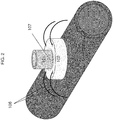
FIG.2 shows a detail of the stopper/pledget (101/102) assembly already fixed at the vessel (103) to be cannulated; in the embodiment shown in this figure the pledget is secured to the vessel by means of a minimum of two suture lines (106) and the stopper is engaged to the pledget by means of a suture with an exposed loop (107); -
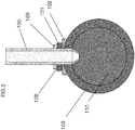
FIG. 3 shows the detail of the cannula (100), according to the invention, when it is in place into the vessel (103) and it is mechanically engaged to the pledget/stopper (101/102) assembly by means of a mechanical joint (108) and it is further secured, for not protruding to far into the vessel, by means of a molded feature (109) which, stopping against the stopper, permits the cannula to enter the aorta only to a fixed dept; -
FIG. 4 shows tourniquets (111) removably attached to the external body of the cannula (100); the suture lines (106), which secures the pledget/stopper (101/102) assembly to the vessel can be introduced into said tourniquets in order to guide the cannula exactly to the cannulation site predisposed by the pledget/stopper (101/102) assembly. - The cannula according to the invention includes three separate components, the cannula body (100), the pledget and stopper assembly (101/102), and the introducer (104).
- The cannula shape and its dimensions are preferably according to those already known in the art.
- The introducer (104) is a semi rigid tube placed coaxially inside the cannula to facilitate cannula placement and can include a hole for wire introducer commonly used to guide the introducer and cannula assembly to the required location. The introducer can be made from a semi-rigid material such as a polyolephin or other plastic that will assist in guiding the cannula assembly to the designated cannulation site. Specific to this embodiment, the introducer includes a sharp end that protrudes past the cannula tip, either the material itself being sharp enough to piece the vessel at the cannulation site or a small blade 1 to 3 mm in depth could be included in the introducer tip to permit simple and easy vessel penetration at the cannulation site.
- The tip of the cannula can be designed in any shape or manner desired to reduce the damage to the blood or improve the flow out of the cannula, in this embodiment the minimum recommended tip depth into the vessel is 10 mm. The tip of the cannula has a diameter smaller than the introducer in order to avoid that the introducer blade or sharp edge could protrude outside the cannula tip more than 1-5 mm, more preferably 1-3 mm.
- One of the essential features of the present invention is that the pledget and stopper assembly (101/102) mates, snaps or otherwise interfaces with the external body of the cannula, engaged in a mechanical joint (108) based on interference or a ball-detent mechanism or male/female joint similar to that found on an ink pen cap. The stopper prevents the cannula and introducer assembly from moving too deeply into the cannulation site beyond a point established by the design of the stopper, and acts as a safety mechanism preventing accidental puncture of the opposite wall of the blood vessel being cannulated. Furthermore the external cannula body could present a molded feature (109) that permits the cannula to enter the aorta to a fixed depth, no more (the maximum recommended tip depth into the vessel is 15 mm). The molded feature (109) is a, further to the mechanical engagement (108), second secure stopper at the stopper.
- The resulting cannulation is done in an inherently safer way than compared to similar embodiments as described in
US patent 6,488,693 by Gannoe, et al. - The introducer and cannula assembly piece the vessel to a fixed depth established by the design of the stopper. Once the cannula is in place in the stopper, the introducer is withdrawn and thrown away. The introducer is withdrawn in a hemostatic manner, meaning that the cannula fills with blood as the introducer is withdrawn, and when the introducer is almost completely out of the cannula, the surgeon then clamps the proximal end of the cannula, preventing blood from coming out of the cannula.
- The pledget-stopper assembly (101 and 102) are sutured to the vessel to be cannulated (103) and is used to guide the cannula and introducer (100 and 104), with the cannulation site being at the center of the pledget-stopper assembly . The pledget can made in such a way that once the cannula and stopper are extracted, the pledget (102) remains connected to the vessel (103).
- The pledget-stopper assembly may include a minimum of two suture lines (106) that are used to fix the pledget to the vessel to be cannulated; these suture lines can be included in the assembly or may be fixed onto the pledget by the surgeon manually. The stopper can be made of any material, preferably a polycarbonate or other moldable plastic that interfaces mechanically with the tip of the cannula as described above. The pledget is made from typical pledget/bandage material, like a sturdy wool or other bandage material that is flexible enough to take the shape of the curvature of the vessel (103) to which it is attached. The sutures included on the pledget are used to sew the assembly to the vessel. A minimum of two sutures with needles included at each end of the suture line are preferable but more than two lines can easily be included as an improvement or other embodiment of the invention.
- As the cannula and connected stopper are removed from the cannulation site, the pledget is then used to close the hole left behind in the vessel (i.e. cannulation site) preventing blood loss. This is a very advantageous additional feature of the invention because the surgeon often does not have clear visible access to the aorta and cannulation site in a MICS mini thoracotomy or mini sternotomy approach. Being able to leave a pledget on the vessel and using the suture lines (106) to close the vessel, as described below, is therefore highly advantageous due to this lack of visualization.
- Therefore the pledget and stopper are preferably each other joined mechanically in a manner that will permit easy detachment of the stopper once the procedure is complete and the cannula needs to be removed. One embodiment could be using a suture with an exposed loop (107) joining the stopper to the pledget; the exposed loop could be cut, breaking the suture which joins the stopper to the pledget, so that the suture line could be extracted, freeing the stopper from the pledget. The stopper remains attached to the cannula and is extracted along with the cannula when the assembly is removed, while the pledget remains attached to the vessel. By crossing the sutures (106) the vessel can be easily closed when the sutures are crossed and tied off manually with a knot or using a more sophisticated tie off technique, permitting simple closure of the cannulation site.
- Again, at least two suture lines would be required, however any number more than two could be realized in this design.
- In many cases the cannulation site is not entirely visible, so a method for aligning the central axis of the stopper with the tip of the cannula is highly advantageous.
- Such a technique can permit the proper landing of the cannula tip to the seat of the pledget stopper assembly, and can be provided quite easily by the use of the suture strings (106) and a mechanical guide on the body of the cannula which permits the use of the suture strings to guide the tip of the cannula directly into the stopper. These same suture strings (106) can then be placed into a tube (typically called a tourniquet (111) and mechanically attached diametrically opposed to the external surface of the cannula. This allows the tourniquet assembly with the suture lines inside to be safely secured out of the field of view, which is important particularly if the surgical incision and consequent surgical field is quite small.
Claims (5)
- An arterial cannula (100) for cardiac surgery comprising
an introducer (104), which has suitable dimension for being placed coaxially inside the cannula, said introducer having at its end a blade or a sharp edge that protrudes the cannula tip no more than 5 mm, the arterial cannula (100) being characterized in that
the cannula (100) further comprises a pledget and stopper (101/102) assembly mechanically mating with the external surface of the cannula in proximity to its tip,
whereby the pledget and stopper assembly (101/102) mates with the external body of the cannula, engaged in a mechanical joint (108) that is based on interference or a ball-detent mechanism or male/female joint. - Arterial cannula according to claim 1 comprising at its external surface a molded feature (109) that is, further to the mechanical engagement (108), a second secure stopper at the stopper (102).
- Arterial cannula according to any of claims 1-2 wherein the pledget-stopper assembly include a minimum of two suture lines (106) that are used to fix the pledget to the vessel to be cannulated.
- Arterial cannula according to any of claims 1-3 wherein the pledget and stopper are each other joined mechanically in a manner that will permit easy detachment of the stopper once the procedure is complete and the cannula needs to be removed.
- Arterial cannula according to any of claims 1-4 comprising at least two tourniquets (111) attached diametrically opposed to the external surface of the cannula.
Applications Claiming Priority (2)
| Application Number | Priority Date | Filing Date | Title |
|---|---|---|---|
| IT000116A ITFI20110116A1 (en) | 2011-06-07 | 2011-06-07 | ARTERIAL CANNULA FOR CARDIAC SURGERY. |
| PCT/EP2012/060715 WO2012168306A1 (en) | 2011-06-07 | 2012-06-06 | Arterial cannula for cardiac surgery |
Publications (2)
| Publication Number | Publication Date |
|---|---|
| EP2717957A1 EP2717957A1 (en) | 2014-04-16 |
| EP2717957B1 true EP2717957B1 (en) | 2018-01-31 |
Family
ID=44554602
Family Applications (1)
| Application Number | Title | Priority Date | Filing Date |
|---|---|---|---|
| EP12732558.7A Not-in-force EP2717957B1 (en) | 2011-06-07 | 2012-06-06 | Arterial cannula for cardiac surgery |
Country Status (7)
| Country | Link |
|---|---|
| US (1) | US20140200551A1 (en) |
| EP (1) | EP2717957B1 (en) |
| JP (1) | JP6034858B2 (en) |
| AU (1) | AU2012266415B2 (en) |
| CA (1) | CA2837421C (en) |
| IT (1) | ITFI20110116A1 (en) |
| WO (1) | WO2012168306A1 (en) |
Families Citing this family (13)
| Publication number | Priority date | Publication date | Assignee | Title |
|---|---|---|---|---|
| WO2017066495A1 (en) * | 2015-10-13 | 2017-04-20 | Entourage Medical Technologies, Inc. | Surgical closure configurations |
| EP3634528B1 (en) | 2017-06-07 | 2023-06-07 | Shifamed Holdings, LLC | Intravascular fluid movement devices, systems, and methods of use |
| US11511103B2 (en) | 2017-11-13 | 2022-11-29 | Shifamed Holdings, Llc | Intravascular fluid movement devices, systems, and methods of use |
| EP3746149B1 (en) | 2018-02-01 | 2025-08-06 | Shifamed Holdings, LLC | Intravascular blood pumps |
| US11857320B2 (en) | 2018-06-08 | 2024-01-02 | Smiths Medical Asd, Inc. | Blood sequestration device and method |
| WO2020028537A1 (en) | 2018-07-31 | 2020-02-06 | Shifamed Holdings, Llc | Intravascaular blood pumps and methods of use |
| WO2020073047A1 (en) | 2018-10-05 | 2020-04-09 | Shifamed Holdings, Llc | Intravascular blood pumps and methods of use |
| WO2021011473A1 (en) | 2019-07-12 | 2021-01-21 | Shifamed Holdings, Llc | Intravascular blood pumps and methods of manufacture and use |
| US12465748B2 (en) | 2019-08-07 | 2025-11-11 | Supira Medical, Inc. | Catheter blood pumps and collapsible pump housings |
| EP4501393A3 (en) | 2019-09-25 | 2025-04-09 | Shifamed Holdings, LLC | Catheter blood pumps and collapsible pump housings |
| WO2021062260A1 (en) | 2019-09-25 | 2021-04-01 | Shifamed Holdings, Llc | Catheter blood pumps and collapsible blood conduits |
| EP4072650A4 (en) | 2019-12-11 | 2024-01-10 | Shifamed Holdings, LLC | DESCENDING AORTA AND VEINA CAVA BLOOD PUMPS |
| EP4077947A4 (en) | 2019-12-19 | 2024-01-10 | Shifamed Holdings, LLC | Intravascular blood pumps, motors, and fluid control |
Family Cites Families (12)
| Publication number | Priority date | Publication date | Assignee | Title |
|---|---|---|---|---|
| US648863A (en) | 1899-12-16 | 1900-05-01 | George W Fair | Camp-stool. |
| JP2694384B2 (en) * | 1990-11-26 | 1997-12-24 | 日本ゼオン株式会社 | Medical tube and medical tube holder |
| US5474539A (en) * | 1991-02-07 | 1995-12-12 | Origin Medsystems, Inc. | Trocar with retracting tip |
| AU781509B2 (en) * | 2000-01-26 | 2005-05-26 | James R. Gannoe | Vascular incisor and method |
| US20040102730A1 (en) * | 2002-10-22 | 2004-05-27 | Davis Thomas P. | System and method for facilitating hemostasis of blood vessel punctures with absorbable sponge |
| DE602004026114D1 (en) * | 2004-01-16 | 2010-04-29 | Top Kk | indwelling |
| US9283314B2 (en) * | 2005-09-21 | 2016-03-15 | Abiomed, Inc. | Cannula systems |
| US8613728B2 (en) * | 2005-11-07 | 2013-12-24 | Flexicath Ltd. | Removable adapter for a splittable introducer and method of use thereof |
| US7905884B2 (en) * | 2006-04-27 | 2011-03-15 | Warsaw Orthopedic, Inc. | Method for use of dilating stylet and cannula |
| EP2046420B1 (en) * | 2006-08-02 | 2014-03-26 | Unomedical A/S | Insertion device |
| WO2008065646A1 (en) * | 2006-11-28 | 2008-06-05 | Medingo Ltd. | An insertion device and method for inserting a subcutaneously insertable element into a body |
| US20100160725A1 (en) * | 2008-12-19 | 2010-06-24 | Andy Christopher Kiser | Methods and Devices for Endoscopic Access to the Heart |
-
2011
- 2011-06-07 IT IT000116A patent/ITFI20110116A1/en unknown
-
2012
- 2012-06-06 AU AU2012266415A patent/AU2012266415B2/en not_active Ceased
- 2012-06-06 JP JP2014514053A patent/JP6034858B2/en not_active Expired - Fee Related
- 2012-06-06 US US14/124,594 patent/US20140200551A1/en not_active Abandoned
- 2012-06-06 WO PCT/EP2012/060715 patent/WO2012168306A1/en not_active Ceased
- 2012-06-06 EP EP12732558.7A patent/EP2717957B1/en not_active Not-in-force
- 2012-06-06 CA CA2837421A patent/CA2837421C/en not_active Expired - Fee Related
Also Published As
| Publication number | Publication date |
|---|---|
| JP6034858B2 (en) | 2016-11-30 |
| US20140200551A1 (en) | 2014-07-17 |
| EP2717957A1 (en) | 2014-04-16 |
| ITFI20110116A1 (en) | 2012-12-08 |
| JP2014523760A (en) | 2014-09-18 |
| CA2837421A1 (en) | 2012-12-13 |
| WO2012168306A1 (en) | 2012-12-13 |
| AU2012266415B2 (en) | 2015-01-22 |
| CA2837421C (en) | 2017-02-28 |
Similar Documents
| Publication | Publication Date | Title |
|---|---|---|
| CA2837421C (en) | Arterial cannula for cardiac surgery | |
| AU2012266415A1 (en) | Arterial cannula for cardiac surgery | |
| US12376846B2 (en) | Suturing devices and methods for suturing an anatomic structure | |
| JP3759497B2 (en) | Minimally invasive annuloplasty repair segment delivery template system | |
| EP3174478B1 (en) | Coring dilator for defining an aperture in a tissue wall | |
| JP6638975B2 (en) | Transdermal systems, devices, and methods | |
| EP2658480B1 (en) | Exchangeable system for minimally invasive beating heart repair of heart valve leaflets | |
| JP3890589B2 (en) | Intracardiac suture device | |
| US10512482B2 (en) | System and method for scoring the left ventricular endocardium to increase left ventricular compliance | |
| US20070088375A1 (en) | Apparatus and method for forming a hole in a hollow organ | |
| US20110118766A1 (en) | Attachment System, Device and Method | |
| JP2008500125A (en) | Suture device | |
| EP1945111B1 (en) | Apparatus for forming a hole in a hollow organ | |
| US8758376B2 (en) | System and method for attaching a vein, an artery, or a tube in a vascular environment | |
| US8728101B2 (en) | System and method for providing an obturator for enhanced directional capabilities in a vascular environment | |
| US8486094B2 (en) | System and method for providing an obturator for enhanced directional capabilities in a vascular environment | |
| CA3081942C (en) | Cannula for percutaneous minimally invasive cannulation of the vena cava | |
| CN118845111B (en) | Device for suturing blood vessels and method of use thereof | |
| US20090093825A1 (en) | System and Method for Providing a Coil Element in a Vascular Environment | |
| Bashir et al. | Peripheral insertion techniques for the Impella 5.0 circulatory support system | |
| Karimov et al. | Minimally Invasive Mitral Valve Surgery via Right Minithoracotomy | |
| HK1189793A (en) | Exchangeable system for minimally invasive beating heart repair of heart valve leaflets |
Legal Events
| Date | Code | Title | Description |
|---|---|---|---|
| PUAI | Public reference made under article 153(3) epc to a published international application that has entered the european phase |
Free format text: ORIGINAL CODE: 0009012 |
|
| 17P | Request for examination filed |
Effective date: 20131129 |
|
| AK | Designated contracting states |
Kind code of ref document: A1 Designated state(s): AL AT BE BG CH CY CZ DE DK EE ES FI FR GB GR HR HU IE IS IT LI LT LU LV MC MK MT NL NO PL PT RO RS SE SI SK SM TR |
|
| DAX | Request for extension of the european patent (deleted) | ||
| REG | Reference to a national code |
Ref country code: DE Ref legal event code: R079 Ref document number: 602012042539 Country of ref document: DE Free format text: PREVIOUS MAIN CLASS: A61M0025060000 Ipc: A61B0017340000 |
|
| GRAP | Despatch of communication of intention to grant a patent |
Free format text: ORIGINAL CODE: EPIDOSNIGR1 |
|
| RIC1 | Information provided on ipc code assigned before grant |
Ipc: A61B 17/34 20060101AFI20170227BHEP Ipc: A61B 17/00 20060101ALI20170227BHEP |
|
| INTG | Intention to grant announced |
Effective date: 20170330 |
|
| GRAJ | Information related to disapproval of communication of intention to grant by the applicant or resumption of examination proceedings by the epo deleted |
Free format text: ORIGINAL CODE: EPIDOSDIGR1 |
|
| INTC | Intention to grant announced (deleted) | ||
| GRAP | Despatch of communication of intention to grant a patent |
Free format text: ORIGINAL CODE: EPIDOSNIGR1 |
|
| INTG | Intention to grant announced |
Effective date: 20170901 |
|
| GRAS | Grant fee paid |
Free format text: ORIGINAL CODE: EPIDOSNIGR3 |
|
| GRAA | (expected) grant |
Free format text: ORIGINAL CODE: 0009210 |
|
| AK | Designated contracting states |
Kind code of ref document: B1 Designated state(s): AL AT BE BG CH CY CZ DE DK EE ES FI FR GB GR HR HU IE IS IT LI LT LU LV MC MK MT NL NO PL PT RO RS SE SI SK SM TR |
|
| REG | Reference to a national code |
Ref country code: GB Ref legal event code: FG4D Ref country code: CH Ref legal event code: EP |
|
| REG | Reference to a national code |
Ref country code: AT Ref legal event code: REF Ref document number: 966627 Country of ref document: AT Kind code of ref document: T Effective date: 20180215 |
|
| REG | Reference to a national code |
Ref country code: IE Ref legal event code: FG4D |
|
| REG | Reference to a national code |
Ref country code: DE Ref legal event code: R096 Ref document number: 602012042539 Country of ref document: DE |
|
| RAP2 | Party data changed (patent owner data changed or rights of a patent transferred) |
Owner name: GLAUBER, MATTIA |
|
| RIN2 | Information on inventor provided after grant (corrected) |
Inventor name: GLAUBER, MATTIA |
|
| REG | Reference to a national code |
Ref country code: NL Ref legal event code: FP |
|
| REG | Reference to a national code |
Ref country code: FR Ref legal event code: PLFP Year of fee payment: 7 |
|
| REG | Reference to a national code |
Ref country code: LT Ref legal event code: MG4D |
|
| REG | Reference to a national code |
Ref country code: AT Ref legal event code: MK05 Ref document number: 966627 Country of ref document: AT Kind code of ref document: T Effective date: 20180131 |
|
| PG25 | Lapsed in a contracting state [announced via postgrant information from national office to epo] |
Ref country code: HR Free format text: LAPSE BECAUSE OF FAILURE TO SUBMIT A TRANSLATION OF THE DESCRIPTION OR TO PAY THE FEE WITHIN THE PRESCRIBED TIME-LIMIT Effective date: 20180131 Ref country code: FI Free format text: LAPSE BECAUSE OF FAILURE TO SUBMIT A TRANSLATION OF THE DESCRIPTION OR TO PAY THE FEE WITHIN THE PRESCRIBED TIME-LIMIT Effective date: 20180131 Ref country code: NO Free format text: LAPSE BECAUSE OF FAILURE TO SUBMIT A TRANSLATION OF THE DESCRIPTION OR TO PAY THE FEE WITHIN THE PRESCRIBED TIME-LIMIT Effective date: 20180430 Ref country code: ES Free format text: LAPSE BECAUSE OF FAILURE TO SUBMIT A TRANSLATION OF THE DESCRIPTION OR TO PAY THE FEE WITHIN THE PRESCRIBED TIME-LIMIT Effective date: 20180131 Ref country code: LT Free format text: LAPSE BECAUSE OF FAILURE TO SUBMIT A TRANSLATION OF THE DESCRIPTION OR TO PAY THE FEE WITHIN THE PRESCRIBED TIME-LIMIT Effective date: 20180131 |
|
| PG25 | Lapsed in a contracting state [announced via postgrant information from national office to epo] |
Ref country code: RS Free format text: LAPSE BECAUSE OF FAILURE TO SUBMIT A TRANSLATION OF THE DESCRIPTION OR TO PAY THE FEE WITHIN THE PRESCRIBED TIME-LIMIT Effective date: 20180131 Ref country code: PL Free format text: LAPSE BECAUSE OF FAILURE TO SUBMIT A TRANSLATION OF THE DESCRIPTION OR TO PAY THE FEE WITHIN THE PRESCRIBED TIME-LIMIT Effective date: 20180131 Ref country code: SE Free format text: LAPSE BECAUSE OF FAILURE TO SUBMIT A TRANSLATION OF THE DESCRIPTION OR TO PAY THE FEE WITHIN THE PRESCRIBED TIME-LIMIT Effective date: 20180131 Ref country code: GR Free format text: LAPSE BECAUSE OF FAILURE TO SUBMIT A TRANSLATION OF THE DESCRIPTION OR TO PAY THE FEE WITHIN THE PRESCRIBED TIME-LIMIT Effective date: 20180501 Ref country code: LV Free format text: LAPSE BECAUSE OF FAILURE TO SUBMIT A TRANSLATION OF THE DESCRIPTION OR TO PAY THE FEE WITHIN THE PRESCRIBED TIME-LIMIT Effective date: 20180131 Ref country code: AT Free format text: LAPSE BECAUSE OF FAILURE TO SUBMIT A TRANSLATION OF THE DESCRIPTION OR TO PAY THE FEE WITHIN THE PRESCRIBED TIME-LIMIT Effective date: 20180131 Ref country code: IS Free format text: LAPSE BECAUSE OF FAILURE TO SUBMIT A TRANSLATION OF THE DESCRIPTION OR TO PAY THE FEE WITHIN THE PRESCRIBED TIME-LIMIT Effective date: 20180531 Ref country code: BG Free format text: LAPSE BECAUSE OF FAILURE TO SUBMIT A TRANSLATION OF THE DESCRIPTION OR TO PAY THE FEE WITHIN THE PRESCRIBED TIME-LIMIT Effective date: 20180430 |
|
| PG25 | Lapsed in a contracting state [announced via postgrant information from national office to epo] |
Ref country code: AL Free format text: LAPSE BECAUSE OF FAILURE TO SUBMIT A TRANSLATION OF THE DESCRIPTION OR TO PAY THE FEE WITHIN THE PRESCRIBED TIME-LIMIT Effective date: 20180131 Ref country code: EE Free format text: LAPSE BECAUSE OF FAILURE TO SUBMIT A TRANSLATION OF THE DESCRIPTION OR TO PAY THE FEE WITHIN THE PRESCRIBED TIME-LIMIT Effective date: 20180131 Ref country code: RO Free format text: LAPSE BECAUSE OF FAILURE TO SUBMIT A TRANSLATION OF THE DESCRIPTION OR TO PAY THE FEE WITHIN THE PRESCRIBED TIME-LIMIT Effective date: 20180131 |
|
| REG | Reference to a national code |
Ref country code: DE Ref legal event code: R097 Ref document number: 602012042539 Country of ref document: DE |
|
| PG25 | Lapsed in a contracting state [announced via postgrant information from national office to epo] |
Ref country code: SK Free format text: LAPSE BECAUSE OF FAILURE TO SUBMIT A TRANSLATION OF THE DESCRIPTION OR TO PAY THE FEE WITHIN THE PRESCRIBED TIME-LIMIT Effective date: 20180131 Ref country code: DK Free format text: LAPSE BECAUSE OF FAILURE TO SUBMIT A TRANSLATION OF THE DESCRIPTION OR TO PAY THE FEE WITHIN THE PRESCRIBED TIME-LIMIT Effective date: 20180131 Ref country code: CZ Free format text: LAPSE BECAUSE OF FAILURE TO SUBMIT A TRANSLATION OF THE DESCRIPTION OR TO PAY THE FEE WITHIN THE PRESCRIBED TIME-LIMIT Effective date: 20180131 Ref country code: SM Free format text: LAPSE BECAUSE OF FAILURE TO SUBMIT A TRANSLATION OF THE DESCRIPTION OR TO PAY THE FEE WITHIN THE PRESCRIBED TIME-LIMIT Effective date: 20180131 |
|
| PLBE | No opposition filed within time limit |
Free format text: ORIGINAL CODE: 0009261 |
|
| STAA | Information on the status of an ep patent application or granted ep patent |
Free format text: STATUS: NO OPPOSITION FILED WITHIN TIME LIMIT |
|
| 26N | No opposition filed |
Effective date: 20181102 |
|
| REG | Reference to a national code |
Ref country code: CH Ref legal event code: PL |
|
| PG25 | Lapsed in a contracting state [announced via postgrant information from national office to epo] |
Ref country code: SI Free format text: LAPSE BECAUSE OF FAILURE TO SUBMIT A TRANSLATION OF THE DESCRIPTION OR TO PAY THE FEE WITHIN THE PRESCRIBED TIME-LIMIT Effective date: 20180131 |
|
| REG | Reference to a national code |
Ref country code: BE Ref legal event code: MM Effective date: 20180630 |
|
| REG | Reference to a national code |
Ref country code: IE Ref legal event code: MM4A |
|
| PG25 | Lapsed in a contracting state [announced via postgrant information from national office to epo] |
Ref country code: MC Free format text: LAPSE BECAUSE OF FAILURE TO SUBMIT A TRANSLATION OF THE DESCRIPTION OR TO PAY THE FEE WITHIN THE PRESCRIBED TIME-LIMIT Effective date: 20180131 Ref country code: LU Free format text: LAPSE BECAUSE OF NON-PAYMENT OF DUE FEES Effective date: 20180606 |
|
| PG25 | Lapsed in a contracting state [announced via postgrant information from national office to epo] |
Ref country code: LI Free format text: LAPSE BECAUSE OF NON-PAYMENT OF DUE FEES Effective date: 20180630 Ref country code: CH Free format text: LAPSE BECAUSE OF NON-PAYMENT OF DUE FEES Effective date: 20180630 Ref country code: IE Free format text: LAPSE BECAUSE OF NON-PAYMENT OF DUE FEES Effective date: 20180606 |
|
| PG25 | Lapsed in a contracting state [announced via postgrant information from national office to epo] |
Ref country code: BE Free format text: LAPSE BECAUSE OF NON-PAYMENT OF DUE FEES Effective date: 20180630 |
|
| PGFP | Annual fee paid to national office [announced via postgrant information from national office to epo] |
Ref country code: NL Payment date: 20190612 Year of fee payment: 8 Ref country code: IT Payment date: 20190620 Year of fee payment: 8 Ref country code: DE Payment date: 20190521 Year of fee payment: 8 |
|
| PGFP | Annual fee paid to national office [announced via postgrant information from national office to epo] |
Ref country code: FR Payment date: 20190510 Year of fee payment: 8 |
|
| PGFP | Annual fee paid to national office [announced via postgrant information from national office to epo] |
Ref country code: GB Payment date: 20190605 Year of fee payment: 8 |
|
| PG25 | Lapsed in a contracting state [announced via postgrant information from national office to epo] |
Ref country code: MT Free format text: LAPSE BECAUSE OF NON-PAYMENT OF DUE FEES Effective date: 20180606 |
|
| PG25 | Lapsed in a contracting state [announced via postgrant information from national office to epo] |
Ref country code: TR Free format text: LAPSE BECAUSE OF FAILURE TO SUBMIT A TRANSLATION OF THE DESCRIPTION OR TO PAY THE FEE WITHIN THE PRESCRIBED TIME-LIMIT Effective date: 20180131 |
|
| PG25 | Lapsed in a contracting state [announced via postgrant information from national office to epo] |
Ref country code: HU Free format text: LAPSE BECAUSE OF FAILURE TO SUBMIT A TRANSLATION OF THE DESCRIPTION OR TO PAY THE FEE WITHIN THE PRESCRIBED TIME-LIMIT; INVALID AB INITIO Effective date: 20120606 Ref country code: PT Free format text: LAPSE BECAUSE OF FAILURE TO SUBMIT A TRANSLATION OF THE DESCRIPTION OR TO PAY THE FEE WITHIN THE PRESCRIBED TIME-LIMIT Effective date: 20180131 |
|
| PG25 | Lapsed in a contracting state [announced via postgrant information from national office to epo] |
Ref country code: MK Free format text: LAPSE BECAUSE OF NON-PAYMENT OF DUE FEES Effective date: 20180131 Ref country code: CY Free format text: LAPSE BECAUSE OF FAILURE TO SUBMIT A TRANSLATION OF THE DESCRIPTION OR TO PAY THE FEE WITHIN THE PRESCRIBED TIME-LIMIT Effective date: 20180131 |
|
| REG | Reference to a national code |
Ref country code: DE Ref legal event code: R119 Ref document number: 602012042539 Country of ref document: DE |
|
| REG | Reference to a national code |
Ref country code: NL Ref legal event code: MM Effective date: 20200701 |
|
| GBPC | Gb: european patent ceased through non-payment of renewal fee |
Effective date: 20200606 |
|
| PG25 | Lapsed in a contracting state [announced via postgrant information from national office to epo] |
Ref country code: GB Free format text: LAPSE BECAUSE OF NON-PAYMENT OF DUE FEES Effective date: 20200606 Ref country code: FR Free format text: LAPSE BECAUSE OF NON-PAYMENT OF DUE FEES Effective date: 20200630 Ref country code: NL Free format text: LAPSE BECAUSE OF NON-PAYMENT OF DUE FEES Effective date: 20200701 |
|
| PG25 | Lapsed in a contracting state [announced via postgrant information from national office to epo] |
Ref country code: DE Free format text: LAPSE BECAUSE OF NON-PAYMENT OF DUE FEES Effective date: 20210101 |
|
| PG25 | Lapsed in a contracting state [announced via postgrant information from national office to epo] |
Ref country code: IT Free format text: LAPSE BECAUSE OF NON-PAYMENT OF DUE FEES Effective date: 20200606 |