EP2717812B1 - Intraocular lens surgical system - Google Patents
Intraocular lens surgical system Download PDFInfo
- Publication number
- EP2717812B1 EP2717812B1 EP12838539.0A EP12838539A EP2717812B1 EP 2717812 B1 EP2717812 B1 EP 2717812B1 EP 12838539 A EP12838539 A EP 12838539A EP 2717812 B1 EP2717812 B1 EP 2717812B1
- Authority
- EP
- European Patent Office
- Prior art keywords
- iol
- intraocular lens
- interface
- insertion cartridge
- bracket
- Prior art date
- Legal status (The legal status is an assumption and is not a legal conclusion. Google has not performed a legal analysis and makes no representation as to the accuracy of the status listed.)
- Active
Links
- 238000003780 insertion Methods 0.000 claims description 95
- 230000037431 insertion Effects 0.000 claims description 95
- 238000000034 method Methods 0.000 description 30
- 238000001356 surgical procedure Methods 0.000 description 14
- 238000004806 packaging method and process Methods 0.000 description 5
- PPBRXRYQALVLMV-UHFFFAOYSA-N Styrene Chemical compound C=CC1=CC=CC=C1 PPBRXRYQALVLMV-UHFFFAOYSA-N 0.000 description 4
- 239000000463 material Substances 0.000 description 4
- 230000000087 stabilizing effect Effects 0.000 description 4
- 239000004743 Polypropylene Substances 0.000 description 3
- -1 polypropylene Polymers 0.000 description 3
- 229920001155 polypropylene Polymers 0.000 description 3
- 210000004087 cornea Anatomy 0.000 description 2
- 238000002347 injection Methods 0.000 description 2
- 239000007924 injection Substances 0.000 description 2
- 229910052751 metal Inorganic materials 0.000 description 2
- 239000002184 metal Substances 0.000 description 2
- 239000004033 plastic Substances 0.000 description 2
- 229920003023 plastic Polymers 0.000 description 2
- 229920000642 polymer Polymers 0.000 description 2
- 210000001525 retina Anatomy 0.000 description 2
- 229920001169 thermoplastic Polymers 0.000 description 2
- 239000004416 thermosoftening plastic Substances 0.000 description 2
- 208000002177 Cataract Diseases 0.000 description 1
- 241000721047 Danaus plexippus Species 0.000 description 1
- 208000002847 Surgical Wound Diseases 0.000 description 1
- RTAQQCXQSZGOHL-UHFFFAOYSA-N Titanium Chemical compound [Ti] RTAQQCXQSZGOHL-UHFFFAOYSA-N 0.000 description 1
- 229920006397 acrylic thermoplastic Polymers 0.000 description 1
- 229910052782 aluminium Inorganic materials 0.000 description 1
- XAGFODPZIPBFFR-UHFFFAOYSA-N aluminium Chemical compound [Al] XAGFODPZIPBFFR-UHFFFAOYSA-N 0.000 description 1
- 239000003795 chemical substances by application Substances 0.000 description 1
- 230000007812 deficiency Effects 0.000 description 1
- 230000001419 dependent effect Effects 0.000 description 1
- 201000010099 disease Diseases 0.000 description 1
- 208000037265 diseases, disorders, signs and symptoms Diseases 0.000 description 1
- 229920001971 elastomer Polymers 0.000 description 1
- 239000000806 elastomer Substances 0.000 description 1
- 230000002708 enhancing effect Effects 0.000 description 1
- 239000000017 hydrogel Substances 0.000 description 1
- 238000002513 implantation Methods 0.000 description 1
- 208000014674 injury Diseases 0.000 description 1
- 230000003340 mental effect Effects 0.000 description 1
- 230000003287 optical effect Effects 0.000 description 1
- 229920003229 poly(methyl methacrylate) Polymers 0.000 description 1
- 229920001296 polysiloxane Polymers 0.000 description 1
- 229910001220 stainless steel Inorganic materials 0.000 description 1
- 239000010935 stainless steel Substances 0.000 description 1
- 230000001954 sterilising effect Effects 0.000 description 1
- 238000004659 sterilization and disinfection Methods 0.000 description 1
- ISXSCDLOGDJUNJ-UHFFFAOYSA-N tert-butyl prop-2-enoate Chemical compound CC(C)(C)OC(=O)C=C ISXSCDLOGDJUNJ-UHFFFAOYSA-N 0.000 description 1
- 239000010936 titanium Substances 0.000 description 1
- 229910052719 titanium Inorganic materials 0.000 description 1
- 230000008733 trauma Effects 0.000 description 1
Images


Classifications
-
- A—HUMAN NECESSITIES
- A61—MEDICAL OR VETERINARY SCIENCE; HYGIENE
- A61F—FILTERS IMPLANTABLE INTO BLOOD VESSELS; PROSTHESES; DEVICES PROVIDING PATENCY TO, OR PREVENTING COLLAPSING OF, TUBULAR STRUCTURES OF THE BODY, e.g. STENTS; ORTHOPAEDIC, NURSING OR CONTRACEPTIVE DEVICES; FOMENTATION; TREATMENT OR PROTECTION OF EYES OR EARS; BANDAGES, DRESSINGS OR ABSORBENT PADS; FIRST-AID KITS
- A61F2/00—Filters implantable into blood vessels; Prostheses, i.e. artificial substitutes or replacements for parts of the body; Appliances for connecting them with the body; Devices providing patency to, or preventing collapsing of, tubular structures of the body, e.g. stents
- A61F2/02—Prostheses implantable into the body
- A61F2/14—Eye parts, e.g. lenses, corneal implants; Implanting instruments specially adapted therefor; Artificial eyes
- A61F2/16—Intraocular lenses
- A61F2/1662—Instruments for inserting intraocular lenses into the eye
- A61F2/1678—Instruments for inserting intraocular lenses into the eye with a separate cartridge or other lens setting part for storage of a lens, e.g. preloadable for shipping
-
- A—HUMAN NECESSITIES
- A61—MEDICAL OR VETERINARY SCIENCE; HYGIENE
- A61F—FILTERS IMPLANTABLE INTO BLOOD VESSELS; PROSTHESES; DEVICES PROVIDING PATENCY TO, OR PREVENTING COLLAPSING OF, TUBULAR STRUCTURES OF THE BODY, e.g. STENTS; ORTHOPAEDIC, NURSING OR CONTRACEPTIVE DEVICES; FOMENTATION; TREATMENT OR PROTECTION OF EYES OR EARS; BANDAGES, DRESSINGS OR ABSORBENT PADS; FIRST-AID KITS
- A61F2/00—Filters implantable into blood vessels; Prostheses, i.e. artificial substitutes or replacements for parts of the body; Appliances for connecting them with the body; Devices providing patency to, or preventing collapsing of, tubular structures of the body, e.g. stents
- A61F2/02—Prostheses implantable into the body
- A61F2/14—Eye parts, e.g. lenses, corneal implants; Implanting instruments specially adapted therefor; Artificial eyes
- A61F2/16—Intraocular lenses
- A61F2/1662—Instruments for inserting intraocular lenses into the eye
-
- A—HUMAN NECESSITIES
- A61—MEDICAL OR VETERINARY SCIENCE; HYGIENE
- A61F—FILTERS IMPLANTABLE INTO BLOOD VESSELS; PROSTHESES; DEVICES PROVIDING PATENCY TO, OR PREVENTING COLLAPSING OF, TUBULAR STRUCTURES OF THE BODY, e.g. STENTS; ORTHOPAEDIC, NURSING OR CONTRACEPTIVE DEVICES; FOMENTATION; TREATMENT OR PROTECTION OF EYES OR EARS; BANDAGES, DRESSINGS OR ABSORBENT PADS; FIRST-AID KITS
- A61F9/00—Methods or devices for treatment of the eyes; Devices for putting-in contact lenses; Devices to correct squinting; Apparatus to guide the blind; Protective devices for the eyes, carried on the body or in the hand
- A61F9/0008—Introducing ophthalmic products into the ocular cavity or retaining products therein
- A61F9/0017—Introducing ophthalmic products into the ocular cavity or retaining products therein implantable in, or in contact with, the eye, e.g. ocular inserts
Definitions
- the present disclosure relates to optical surgery, and more specifically to surgery for replacement of a patient's lens.
- the human eye in simple terms, functions to provide vision by transmitting and refracting light through a clear outer portion called the cornea and focusing the image by way of the lens onto the retina at the back of the eye.
- the quality of the focused image depends on many factors including the size, shape, and length of the eye, and the shape and transparency of the cornea and lens.
- IOL intraocular lens
- WO 2005/084588 relates to Devices and Methods for Storing Loading and Delivering an Intraocular Lens.
- a cartridge for delivering an intraocular lens into the eye of a subject that comprises a body disposed along a longitudinal axis having a distal end and a proximal end, and a tapered lumen disposed along the longitudinal axis having an aperture at the distal end of the body.
- the cartridge may be loaded with an intraocular lens using a packaging system.
- US20070123980 also relates to a lens and cartridge packaging system.
- a system for intraocular lens (IOL) surgery includes an IOL insertion cartridge and an IOL interface adapted to engage an IOL lens for advancement through the IOL insertion cartridge.
- the system also includes a bracket that is detachably attached to the IOL insertion cartridge and that facilitates securing of the IOL interface relative to the IOL insertion cartridge.
- the bracket forms a cavity between itself and the IOL insertion cartridge for securing at least a portion of the IOL interface.
- the cavity is sized to hold the IOL interface in place by friction between the IOL interface and the bracket and the IOL insertion cartridge.
- the IOL insertion cartridge also includes protuberances that form part of the cavity.
- the bracket includes a detent that inhibits the IOL interface from being advanced through the cavity during engagement with an IOL insertion tool. Moreover, the detent may be used for storing energy in the IOL interface to aid in removing it from the system.
- the bracket attaches to the IOL insertion cartridge due to a friction fit.
- the bracket includes a truncated V -shaped body with wings that engage the IOL insertion cartridge. Additionally, the truncated portion of the V -shaped body may form part of a cavity for securing the IOL interface.
- a process for using an IOL surgical system including positionally stabilizing an assembly including an IOL insertion cartridge, an IOL interface, and a detachable bracket and removing the IOL interface from the assembly.
- the process may also include detaching the bracket from the IOL insertion cartridge.
- a process for making an IOL surgical system may include detachably attaching an IOL insertion cartridge to a bracket that facilitates securing of an IOL interface relative to the IOL insertion cartridge and engaging an IOL interface with the bracket.
- a system for IOL surgery may allow an IOL interface to be co-located with an IOL insertion cartridge, which assists in preventing the IOL interface, which may often be relatively small, from being lost.
- a system may allow an IOL interface to be positioned relative to an IOL insertion cartridge in a stable manner.
- grasping the IOL insertion cartridge which is typically much larger than the IOL interface and, hence, easier to grasp (whether by hand or tool), allows control over the IOL interface.
- grasping the IOL insertion cartridge which is typically much larger than the IOL interface and, hence, easier to grasp (whether by hand or tool)
- manual grasping of it through a surgical glove may be difficult, especially if the glove is wet. Additionally, this eliminates a handling operation, and a separate assembly device is not required.
- an IOL interface may be readily presented for engagement with an IOL insertion tool, which may ease the engagement process.
- FIG. 1 illustrates an example system 100 for intraocular lens (IOL) surgery.
- System 100 includes an IOL insertion cartridge 110, an IOL interface 120, and a detachable bracket 130.
- IOL insertion cartridge 110 facilitates the insertion of an IOL into a patient's eye.
- IOL insertion cartridge 110 includes a body 112 and a passage 114 through the body.
- a foldable IOL which may be made of silicone, soft acrylics, hydrogels, or other appropriate materials, is moved through passage 114 in preparation for insertion into the eye.
- passage 114 has an asymmetric bore, which assists in folding an IOL.
- a common IOL may be approximately 6 mm in diameter, and with haptics can be up to around 13 mm. However, surgical incisions are typically much smaller (e.g., 2 to 3 mm in width). An IOL is therefore typically folded before insertion through the incision.
- passage 114 may also taper along its length (e.g., to a circular or elliptical bore) to assist in folding an IOL.
- the IOL is folded due to the shape of the passage.
- At the end of the passage e.g., the injection point
- there is typically a relatively small diameter injection nozzle through which the lens may be advanced into the eye.
- IOL insertion cartridge 110 also includes a pair of protuberances 119, which extend from body 112. Protuberances 119 may generally assist in the placing and securing of IOL interface 120. In the illustrated implementation, protuberances 119 are a pair of parallel legs spaced apart from each other sufficiently to allow the IOL interface to be placed between them. Protuberances 119 may therefore assist in placing, aligning, and securing of the IOL interface.
- IOL insertion cartridge 110 further includes sides 116a, 116b. Sides 116a, 116b may assist in the grasping (by tool or hand) of IOL insertion cartridge 110, and system 100 accordingly. At one end of IOL insertion cartridge, sides 116a, 116b taper outward to form wings 117, which are used in securing detachable bracket 130 to the IOL insertion cartridge, as discussed in more detail below. Wings 117 include detents 118, which may assist in positioning detachable bracket 130 on wings 117.
- IOL insertion cartridge 110 may be molded as a single piece from any suitable thermoplastic, such as polypropylene.
- the thermoplastic may contain a lubricity enhancing agent.
- IOL interface 120 is responsible for interfacing with an IOL to advance it through IOL insertion cartridge 110.
- IOL interface 120 includes a body 122 having a generally cylindrical shape and a first end 124a and a second end 124b.
- First end 124a includes a port 126 into which an IOL insertion tool may be inserted.
- IOL interface 120 may, for example, engage with an IOL insertion tool due to a friction fit.
- Second end 126a may be closed.
- IOL interface 120 may be made of a commercial injection-molded elastomer, polymer (e.g., polypropylene or styrene) or any other appropriate material. In particular implementations, IOL interface may be approximately 2 to 3 mm in diameter.
- Detachable bracket 130 is adapted to detachably attach to IOL insertion cartridge 110 and secure IOL interface 120 relative to the IOL insertion cartridge 110.
- detachable bracket 130 includes a body 132 having a truncated V-shape. The ends of the V-shape are flattened to provide support surfaces for IOL insertion cartridge 110. Coupled to the ends of the V-shape are wings 134. Wings 134 are spaced apart from each other to receive wings 117 of IOL insertion cartridge 110. Each of wings 134 includes a tab 135. Tabs 135 form cavities into which wings 117 of IOL deliver cartridge fit and are be spaced from the flattened portions of body 132 to provide a fiction fit for wings 117.
- Detachable bracket 130 also includes a detent 136 that retards the movement of IOL interface 120 during use.
- detent 136 extends from the truncated portion of body 132 and includes a protuberance 137.
- Protuberance 137 is sized to interact with end 124b of IOL interface 120.
- Detachable frame 130 may be composed of plastic (e.g., styrene, polypropylene, or any other commercially available injection-molded polymer), metal (e.g., titanium, stainless steel, or aluminum), or any other appropriate material.
- detachable bracket 130 is approximately 3 mm in width (i.e., in the longitudinal direction of body 112) and 1 mm in thickness.
- detachable bracket 130 may be sized.
- detachable bracket 120 may be sized according to a desired application.
- detachable bracket 130 may also have other shapes. For example, instead of a truncated V-shape, detachable bracket 130 may have a square or rectangular shape.
- detachable bracket 130 may be appropriately sized and configured to work with various IOL cartridge designs.
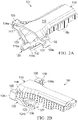
- FIGs. 2A-B illustrate system 100 in an assembled state.
- IOL insertion cartridge 110 has been engaged with detachable bracket 130 by having wings 117 inserted between wings 134 and between the flattened portions of body 132 and tabs 135. Wings 117 may, for example, be held in place due to a friction fit.
- IOL interface 120 has been engaged with system 100 by being captured in a cavity formed between the truncated portion of body 132, protuberances 119, and a portion of body 112. IOL interface 120 may be held in the cavity due to a friction fit.
- end 124b of IOL interface 120 is inhibited from moving beyond a particular location along IOL insertion cartridge 110 by protuberance 137 of detent 136. This may prevent IOL interface 120 from sliding through the cavity formed between IOL insertion cartridge 110 and detachable bracket 130, during assembly and/or use. Additionally, tabs 135 may abut detents 118 to prevent detachable bracket 130 from sliding along the longitudinal direction of body 112, which may assist in securely mounting detachable bracket 130 to IOL insertion cartridge 110.
- system 100 arrives in an assembled, sterilized state at a surgical site (e.g., hospital).
- System 100 may then be positionally stabilized (by a tool or by hand), and a tool that is used to advance an IOL through IOL insertion cartridge 100 may be engaged with IOL interface 120.
- a tool that is used to advance an IOL through IOL insertion cartridge 100 may be engaged with IOL interface 120.
- an IOL insertion tool may be inserted into port 126 of IOL interface 120, and a friction fit may be formed between the two components due to the insertion.
- An IOL insertion tool may, for example, be a plunger-style system that includes an outer shell and a plunger.
- the outer shell may have passage therethrough, and the plunger may be adapted to move in the passage, the plunger movements causing the IOL to move.
- the shell and plunger may, for example, be generally cylindrical in shape.
- the plunger system may be made of plastic, metal, or any other appropriate material.
- An example IOL insertion tool is a Monarch ® handpiece produced by Alcon Laboratories, Inc., of 6201 South Freeway, Fort Worth, TX 76134. However, other types of IOL insertion tools may be used.
- detent 136 may prevent IOL interface 120 from being advanced out of the cavity. Furthermore, detent 136 may assist in building up energy in IOL interface 120 to assist in removing the IOL interface from system 100.
- the IOL interface 120 may be removed from system 100.
- the IOL interface 120 may be pulled from the cavity formed between IOL insertion cartridge 110 and detachable bracket 130.
- the detachable bracket 130 may then be detached from the IOL insertion cartridge.
- the detachable bracket 130 may be slid relative to the longitudinal axis of the IOL insertion cartridge 110 such that a friction fit between wings 117 and wings 134 is released. Thereafter, the detachable bracket 130 may be discarded.
- the IOL interface 120 may be used for advancing an IOL through IOL insertion cartridge 110 for insertion into an eye.
- System 100 provides a variety of features. For example, system 100 allows IOL interface 120 to be co-located with IOL insertion cartridge 110. Because the IOL interface 120 may be small in size, being co-located with the IOL insertion cartridge 110 may aid in preventing the IOL interface 120 from being lost. As another example, system 100 allows IOL interface 120 to be positioned relative to IOL insertion cartridge 110 in a stable manner. Thus, by grasping IOL insertion cartridge 110, which is typically much larger than IOL interface 120 and, hence, easier to grasp (whether by hand or tool), control may be had over the IOL interface 120.
- the IOL interface 120 may be small in size in some instances, manual grasping of the IOL interface 120, particularly while wearing surgical gloves, may be difficult. This difficulty may be further exasperated if the gloves are wet.
- co-locating the IOL interface 120 with the IOL insertion cartridge 110 eliminates a handling operation, and a separate assembly device for handling the IOL interface 120 is not required.
- IOL interface 120 may be readily presented for engagement with an IOL insertion tool, which may ease the engagement process. Moreover, the presentation may be quite intuitive, which may ease mental burden.
- detachable bracket 130 may be easily detached from IOL insertion cartridge 110 once the IOL interface 120 is removed from system 100.
- IOL interface 120 is able to be implemented while increasing packaging space a relatively small amount. Moreover, additional packagings are not required.
- FIGs. 1-2 illustrate one example implementation of an IOL surgical system 100
- other implementations may include fewer, additional, and/or a different arrangement of components.
- IOL insertion cartridge 110 may not include wings 117.
- the detachable bracket 130 may engage IOL insertion cartridge 110 by different techniques. For instance, the detachable bracket 130 may engage the sides and/or the top and/or bottom of an IOL insertion cartridge 110.
- the passage 114 may have other configurations.
- the passage 114 may round, elliptical, or other desired or suitable cross-sectional shapes.
- the IOL insertion cartridge 110 may not include protuberances 119.
- the IOL interface 120 may be secured to system 100 in other manners.
- a cavity in which the IOL interface 120 is disposed may be formed between body 112 and body 132.
- IOL interface 120 may be engaged primarily with detachable bracket 130.
- FIG. 3 illustrates an example process 300 for using a system for IOL surgery.
- process 300 may, for instance, be performed using a system similar to system 100.
- Process 300 calls for positionally stabilizing an assembly that includes an IOL insertion cartridge, an IOL interface, and a detachable bracket that holds the IOL interface stable relative to the IOL insertion cartridge (operation 304).
- the assembly may be positionally stabilized by being grasped (e.g., by a tool or hand).
- Process 300 also calls for engaging an IOL insertion tool with the IOL interface (operation 308).
- an IOL insertion tool may be inserted into a port of the IOL interface and a friction fit may be formed between the two components due to the insertion.
- Process 300 additionally calls for removing the IOL interface from the assembly (operation 312).
- the IOL interface may be pulled from a cavity formed between the IOL insertion cartridge and the detachable bracket.
- Process 300 further calls for detaching the detachable bracket from the IOL insertion cartridge (operation 316).
- the detachable bracket may be slid relative to the IOL insertion cartridge such that a friction fit between the two is released. In some instances, the released detachable bracket may be discarded.
- process 300 illustrates one example of a process for using a system for IOL surgery
- other processes for using an IOL surgical system may include fewer, additional, and or a different arrangement of operations.
- a process may not include detaching the detachable bracket.
- a process may include using the IOL interface to advance an IOL through the IOL insertion cartridge.
- a process may include advancing the IOL interface against a detent to build energy for removing the IOL interface.
- FIG. 4 illustrates an example process 400 for making a system for IOL surgery.
- process 400 may be used to form a system similar to system 100.
- Process 404 calls for positionally stabilizing a bracket adapted to engage an IOL interface (operation 404).
- the bracket may, for example, be stabilized by tool or manually.
- Process 400 also calls for detachably attaching an IOL insertion cartridge to the bracket (operation 408).
- a detachable attachment may be a friction fit.
- Process 400 further calls for engaging an IOL interface with the bracket (operation 412).
- an IOL interface may be engaged with a bracket by being inserted into a cavity formed between the bracket and an attached IOL insertion cartridge.
- the IOL interface may be held in the cavity by a friction fit.
- process 400 illustrates one example of a process for making a system for IOL surgery
- other processes for making an IOL surgical system may include fewer, additional, and/or a different arrangement of operations.
- a process may include positionally stabilizing the IOL insertion cartridge and detachably attaching the bracket to the IOL insertion cartridge.
- the IOL interface may be engaged with the bracket before the bracket is engaged with the IOL insertion cartridge.
- Other operations such as sterilization or packaging, may also be performed in particular implementations.
Description
- The present disclosure relates to optical surgery, and more specifically to surgery for replacement of a patient's lens.
- The human eye, in simple terms, functions to provide vision by transmitting and refracting light through a clear outer portion called the cornea and focusing the image by way of the lens onto the retina at the back of the eye. The quality of the focused image depends on many factors including the size, shape, and length of the eye, and the shape and transparency of the cornea and lens.
- When trauma, age, or disease causes the lens to become Jess transparent, vision deteriorates because of a reduction in light transmitted to the retina. This deficiency in the eye's lens is medically known as a cataract. The treatment for this condition is typically surgical removal of the lens and implantation of an artificial lens, often termed an intraocular lens (IOL).
-
WO 2005/084588 relates to Devices and Methods for Storing Loading and Delivering an Intraocular Lens. A cartridge for delivering an intraocular lens into the eye of a subject that comprises a body disposed along a longitudinal axis having a distal end and a proximal end, and a tapered lumen disposed along the longitudinal axis having an aperture at the distal end of the body. The cartridge may be loaded with an intraocular lens using a packaging system.US20070123980 also relates to a lens and cartridge packaging system. - It will be appreciated that the scope of the invention is in accordance with the claims. Accordingly, there is provided an intraocular lens insertion system as defined in claim 1. Optional features are set out in the dependent claim. The specification includes description of arrangements outside the scope of the claims, provided as background and to assist in understanding the invention.
- In one general implementation, a system for intraocular lens (IOL) surgery includes an IOL insertion cartridge and an IOL interface adapted to engage an IOL lens for advancement through the IOL insertion cartridge. The system also includes a bracket that is detachably attached to the IOL insertion cartridge and that facilitates securing of the IOL interface relative to the IOL insertion cartridge.
- The bracket forms a cavity between itself and the IOL insertion cartridge for securing at least a portion of the IOL interface. The cavity is sized to hold the IOL interface in place by friction between the IOL interface and the bracket and the IOL insertion cartridge. The IOL insertion cartridge also includes protuberances that form part of the cavity.
- The bracket includes a detent that inhibits the IOL interface from being advanced through the cavity during engagement with an IOL insertion tool. Moreover, the detent may be used for storing energy in the IOL interface to aid in removing it from the system.
- The bracket, attaches to the IOL insertion cartridge due to a friction fit. The bracket includes a truncated V -shaped body with wings that engage the IOL insertion cartridge. Additionally, the truncated portion of the V -shaped body may form part of a cavity for securing the IOL interface.
- In another general implementation of the specification, not claimed in the present claims, there is provided a process for using an IOL surgical system including positionally stabilizing an assembly including an IOL insertion cartridge, an IOL interface, and a detachable bracket and removing the IOL interface from the assembly. The process may also include detaching the bracket from the IOL insertion cartridge.
- In an additional general implementation of the specification a process for making an IOL surgical system may include detachably attaching an IOL insertion cartridge to a bracket that facilitates securing of an IOL interface relative to the IOL insertion cartridge and engaging an IOL interface with the bracket.
- Various implementations of the specification may include one or more features. For example, a system for IOL surgery may allow an IOL interface to be co-located with an IOL insertion cartridge, which assists in preventing the IOL interface, which may often be relatively small, from being lost. As another example, a system may allow an IOL interface to be positioned relative to an IOL insertion cartridge in a stable manner. Thus, grasping the IOL insertion cartridge, which is typically much larger than the IOL interface and, hence, easier to grasp (whether by hand or tool), allows control over the IOL interface. Moreover, because of the typically small size of an IOL interface, manual grasping of it through a surgical glove may be difficult, especially if the glove is wet. Additionally, this eliminates a handling operation, and a separate assembly device is not required. As a further example, an IOL interface may be readily presented for engagement with an IOL insertion tool, which may ease the engagement process.
- The details and features of various implementations will be conveyed by the following description, along with the drawings.
-
-
FIG. 1 is an exploded view of an example system for intraocular lens surgery. -
FIGs. 2A-B show perspective views of the system ofFIG. 1 in an assembled state. -
FIG. 3 is a flowchart illustrating an example process for using a system for intraocular lens surgery. -
FIG. 4 is a flowchart illustrating an example process for making a system for intraocular lens surgery. -
FIG. 1 illustrates anexample system 100 for intraocular lens (IOL) surgery.System 100 includes an IOLinsertion cartridge 110, anIOL interface 120, and adetachable bracket 130. -
IOL insertion cartridge 110 facilitates the insertion of an IOL into a patient's eye.IOL insertion cartridge 110 includes abody 112 and apassage 114 through the body. During surgery, a foldable IOL, which may be made of silicone, soft acrylics, hydrogels, or other appropriate materials, is moved throughpassage 114 in preparation for insertion into the eye. - As shown,
passage 114 has an asymmetric bore, which assists in folding an IOL. A common IOL may be approximately 6 mm in diameter, and with haptics can be up to around 13 mm. However, surgical incisions are typically much smaller (e.g., 2 to 3 mm in width). An IOL is therefore typically folded before insertion through the incision. In particular implementations,passage 114 may also taper along its length (e.g., to a circular or elliptical bore) to assist in folding an IOL. Thus, as an IOL is advanced throughpassage 114, the IOL is folded due to the shape of the passage. At the end of the passage (e.g., the injection point), there is typically a relatively small diameter injection nozzle through which the lens may be advanced into the eye. - IOL
insertion cartridge 110 also includes a pair of protuberances 119, which extend frombody 112. Protuberances 119 may generally assist in the placing and securing ofIOL interface 120. In the illustrated implementation, protuberances 119 are a pair of parallel legs spaced apart from each other sufficiently to allow the IOL interface to be placed between them. Protuberances 119 may therefore assist in placing, aligning, and securing of the IOL interface. - IOL
insertion cartridge 110 further includessides Sides IOL insertion cartridge 110, andsystem 100 accordingly. At one end of IOL insertion cartridge,sides wings 117, which are used in securingdetachable bracket 130 to the IOL insertion cartridge, as discussed in more detail below. Wings 117 includedetents 118, which may assist in positioningdetachable bracket 130 onwings 117. - In certain implementations,
IOL insertion cartridge 110 may be molded as a single piece from any suitable thermoplastic, such as polypropylene. In particular implementations, the thermoplastic may contain a lubricity enhancing agent. -
IOL interface 120 is responsible for interfacing with an IOL to advance it throughIOL insertion cartridge 110. In this implementation,IOL interface 120 includes abody 122 having a generally cylindrical shape and afirst end 124a and asecond end 124b.First end 124a includes aport 126 into which an IOL insertion tool may be inserted.IOL interface 120 may, for example, engage with an IOL insertion tool due to a friction fit. Second end 126a may be closed.IOL interface 120 may be made of a commercial injection-molded elastomer, polymer (e.g., polypropylene or styrene) or any other appropriate material. In particular implementations, IOL interface may be approximately 2 to 3 mm in diameter. -
Detachable bracket 130 is adapted to detachably attach toIOL insertion cartridge 110 andsecure IOL interface 120 relative to theIOL insertion cartridge 110. In this implementation,detachable bracket 130 includes abody 132 having a truncated V-shape. The ends of the V-shape are flattened to provide support surfaces forIOL insertion cartridge 110. Coupled to the ends of the V-shape are wings 134. Wings 134 are spaced apart from each other to receivewings 117 ofIOL insertion cartridge 110. Each of wings 134 includes atab 135.Tabs 135 form cavities into whichwings 117 of IOL deliver cartridge fit and are be spaced from the flattened portions ofbody 132 to provide a fiction fit forwings 117. -
Detachable bracket 130 also includes adetent 136 that retards the movement ofIOL interface 120 during use. In the illustrated implementation,detent 136 extends from the truncated portion ofbody 132 and includes aprotuberance 137.Protuberance 137 is sized to interact withend 124b ofIOL interface 120. -
Detachable frame 130 may be composed of plastic (e.g., styrene, polypropylene, or any other commercially available injection-molded polymer), metal (e.g., titanium, stainless steel, or aluminum), or any other appropriate material. In the illustrated implementations,detachable bracket 130 is approximately 3 mm in width (i.e., in the longitudinal direction of body 112) and 1 mm in thickness. However,detachable bracket 130 may be sized. For example,detachable bracket 120 may be sized according to a desired application. Further,detachable bracket 130 may also have other shapes. For example, instead of a truncated V-shape,detachable bracket 130 may have a square or rectangular shape. Thus,detachable bracket 130 may be appropriately sized and configured to work with various IOL cartridge designs. -
FIGs. 2A-B illustratesystem 100 in an assembled state. As best illustrated inFIG. 2A ,IOL insertion cartridge 110 has been engaged withdetachable bracket 130 by havingwings 117 inserted between wings 134 and between the flattened portions ofbody 132 andtabs 135.Wings 117 may, for example, be held in place due to a friction fit. Additionally,IOL interface 120 has been engaged withsystem 100 by being captured in a cavity formed between the truncated portion ofbody 132, protuberances 119, and a portion ofbody 112.IOL interface 120 may be held in the cavity due to a friction fit. - As best illustrated in
FIG. 2B ,end 124b ofIOL interface 120 is inhibited from moving beyond a particular location alongIOL insertion cartridge 110 byprotuberance 137 ofdetent 136. This may preventIOL interface 120 from sliding through the cavity formed betweenIOL insertion cartridge 110 anddetachable bracket 130, during assembly and/or use. Additionally,tabs 135 may abutdetents 118 to preventdetachable bracket 130 from sliding along the longitudinal direction ofbody 112, which may assist in securely mountingdetachable bracket 130 toIOL insertion cartridge 110. - In certain modes of operation,
system 100 arrives in an assembled, sterilized state at a surgical site (e.g., hospital).System 100 may then be positionally stabilized (by a tool or by hand), and a tool that is used to advance an IOL throughIOL insertion cartridge 100 may be engaged withIOL interface 120. For example, an IOL insertion tool may be inserted intoport 126 ofIOL interface 120, and a friction fit may be formed between the two components due to the insertion. - An IOL insertion tool may, for example, be a plunger-style system that includes an outer shell and a plunger. The outer shell may have passage therethrough, and the plunger may be adapted to move in the passage, the plunger movements causing the IOL to move. The shell and plunger may, for example, be generally cylindrical in shape. The plunger system may be made of plastic, metal, or any other appropriate material. An example IOL insertion tool is a Monarch® handpiece produced by Alcon Laboratories, Inc., of 6201 South Freeway, Fort Worth, TX 76134. However, other types of IOL insertion tools may be used.
- While the insertion tool is engaged with
IOL interface 120,detent 136 may preventIOL interface 120 from being advanced out of the cavity. Furthermore,detent 136 may assist in building up energy inIOL interface 120 to assist in removing the IOL interface fromsystem 100. - Once the IOL insertion tool is engaged with
IOL interface 120, theIOL interface 120 may be removed fromsystem 100. In particular, theIOL interface 120 may be pulled from the cavity formed betweenIOL insertion cartridge 110 anddetachable bracket 130. Thedetachable bracket 130 may then be detached from the IOL insertion cartridge. For example, thedetachable bracket 130 may be slid relative to the longitudinal axis of theIOL insertion cartridge 110 such that a friction fit betweenwings 117 and wings 134 is released. Thereafter, thedetachable bracket 130 may be discarded. TheIOL interface 120 may be used for advancing an IOL throughIOL insertion cartridge 110 for insertion into an eye. -
System 100 provides a variety of features. For example,system 100 allowsIOL interface 120 to be co-located withIOL insertion cartridge 110. Because theIOL interface 120 may be small in size, being co-located with theIOL insertion cartridge 110 may aid in preventing theIOL interface 120 from being lost. As another example,system 100 allowsIOL interface 120 to be positioned relative toIOL insertion cartridge 110 in a stable manner. Thus, by graspingIOL insertion cartridge 110, which is typically much larger thanIOL interface 120 and, hence, easier to grasp (whether by hand or tool), control may be had over theIOL interface 120. - Further, because the
IOL interface 120 may be small in size in some instances, manual grasping of theIOL interface 120, particularly while wearing surgical gloves, may be difficult. This difficulty may be further exasperated if the gloves are wet. - Additionally, co-locating the
IOL interface 120 with theIOL insertion cartridge 110 eliminates a handling operation, and a separate assembly device for handling theIOL interface 120 is not required. As a further example,IOL interface 120 may be readily presented for engagement with an IOL insertion tool, which may ease the engagement process. Moreover, the presentation may be quite intuitive, which may ease mental burden. As another example,detachable bracket 130 may be easily detached fromIOL insertion cartridge 110 once theIOL interface 120 is removed fromsystem 100. Furthermore,IOL interface 120 is able to be implemented while increasing packaging space a relatively small amount. Moreover, additional packagings are not required. - Although
FIGs. 1-2 illustrate one example implementation of an IOLsurgical system 100, other implementations may include fewer, additional, and/or a different arrangement of components. In some implementations, for example,IOL insertion cartridge 110 may not includewings 117. Thus, in some implementations, thedetachable bracket 130 may engageIOL insertion cartridge 110 by different techniques. For instance, thedetachable bracket 130 may engage the sides and/or the top and/or bottom of anIOL insertion cartridge 110. - Additionally, in some instances, the
passage 114 may have other configurations. For example, in some implementations, thepassage 114 may round, elliptical, or other desired or suitable cross-sectional shapes. Also, in some implementations, theIOL insertion cartridge 110 may not include protuberances 119. Thus, theIOL interface 120 may be secured tosystem 100 in other manners. For example, a cavity in which theIOL interface 120 is disposed may be formed betweenbody 112 andbody 132. In particular implementations,IOL interface 120 may be engaged primarily withdetachable bracket 130. -
FIG. 3 illustrates anexample process 300 for using a system for IOL surgery. For example,process 300 may, for instance, be performed using a system similar tosystem 100. -
Process 300 calls for positionally stabilizing an assembly that includes an IOL insertion cartridge, an IOL interface, and a detachable bracket that holds the IOL interface stable relative to the IOL insertion cartridge (operation 304). For example, in some instances, the assembly may be positionally stabilized by being grasped (e.g., by a tool or hand). -
Process 300 also calls for engaging an IOL insertion tool with the IOL interface (operation 308). For example, an IOL insertion tool may be inserted into a port of the IOL interface and a friction fit may be formed between the two components due to the insertion. -
Process 300 additionally calls for removing the IOL interface from the assembly (operation 312). For example, the IOL interface may be pulled from a cavity formed between the IOL insertion cartridge and the detachable bracket. -
Process 300 further calls for detaching the detachable bracket from the IOL insertion cartridge (operation 316). For example, the detachable bracket may be slid relative to the IOL insertion cartridge such that a friction fit between the two is released. In some instances, the released detachable bracket may be discarded. - Although
process 300 illustrates one example of a process for using a system for IOL surgery, other processes for using an IOL surgical system may include fewer, additional, and or a different arrangement of operations. For example, a process may not include detaching the detachable bracket. As a further example, a process may include using the IOL interface to advance an IOL through the IOL insertion cartridge. As an additional example, a process may include advancing the IOL interface against a detent to build energy for removing the IOL interface. -
FIG. 4 illustrates anexample process 400 for making a system for IOL surgery. In some instances,process 400 may be used to form a system similar tosystem 100. -
Process 404 calls for positionally stabilizing a bracket adapted to engage an IOL interface (operation 404). The bracket may, for example, be stabilized by tool or manually. -
Process 400 also calls for detachably attaching an IOL insertion cartridge to the bracket (operation 408). For example, a detachable attachment may be a friction fit. -
Process 400 further calls for engaging an IOL interface with the bracket (operation 412). For example, in some instances, an IOL interface may be engaged with a bracket by being inserted into a cavity formed between the bracket and an attached IOL insertion cartridge. The IOL interface may be held in the cavity by a friction fit. - Although
process 400 illustrates one example of a process for making a system for IOL surgery, other processes for making an IOL surgical system may include fewer, additional, and/or a different arrangement of operations. In certain implementations, for example, a process may include positionally stabilizing the IOL insertion cartridge and detachably attaching the bracket to the IOL insertion cartridge. Additionally, in some implementations, the IOL interface may be engaged with the bracket before the bracket is engaged with the IOL insertion cartridge. Other operations, such as sterilization or packaging, may also be performed in particular implementations.
Claims (2)
- An intraocular lens insertion system (100) comprising:an intraocular lens insertion tool;an intraocular lens insertion cartridge (110) configured to fold an intraocular lens prior to insertion of said lens into an eye;an intraocular lens interface (120) adapted to engage an intraocular lens for advancement through the intraocular lens insertion cartridge;a bracket (130) detachably attached to the intraocular lens insertion cartridge, the bracket and the intraocular lens insertion cartridge (110) configured to form a first cavity between the bracket and the intraocular lens insertion cartridge, the first cavity configured to secure at least a portion of the intraocular lens interface (120) relative to the intraocular lens insertion cartridge (110), characterized in that:the intraocular lens insertion cartridge (110) has sides (116a, 116b) that taper outwardly to form wings (117);the bracket (130) includes a body (132) having a truncated V-shape, the ends of the V-shape being flattened to define two support surfaces and having wings (134), wherein the wings (134) are spaced apart, and each of the wings (134) including a tab (135) forming second cavities to receive wings (117) of the intraocular lens insertion cartridge (110) to engage the bracket and the intraocular lens insertion cartridge (110);wherein the intraocular lens insertion cartridge (110) comprises protuberances (119a, 119b) defining the first cavity, the protuberances comprising a pair of parallel legs spaced sufficiently apart to allow the intraocular lens interface (120) to be received therebetween; andfurther wherein the bracket (130) comprises a detent (136), in the trough of the truncated V-shape, and a protuberance (137) extending from the detent, wherein the protuberance (137) is configured to abut an end (124b) of the intraocular lens interface (120), and to prevent the intraocular lens interface from sliding though the first cavity during assembly to engage the intraocular lens interface with the intraocular lens insertion tool.
- The system of claim 1, wherein the first cavity is sized to hold the intraocular lens interface (120) in place by friction between the intraocular lens interface (120) and the bracket (130) and the intraocular lens insertion cartridge (110).
Applications Claiming Priority (2)
| Application Number | Priority Date | Filing Date | Title |
|---|---|---|---|
| US13/252,548 US8690941B2 (en) | 2011-10-04 | 2011-10-04 | Intraocular lens surgical system and method |
| PCT/US2012/054413 WO2013052238A1 (en) | 2011-10-04 | 2012-09-10 | Intraocular lens surgical system and method |
Publications (3)
| Publication Number | Publication Date |
|---|---|
| EP2717812A1 EP2717812A1 (en) | 2014-04-16 |
| EP2717812A4 EP2717812A4 (en) | 2015-08-19 |
| EP2717812B1 true EP2717812B1 (en) | 2022-11-30 |
Family
ID=47993309
Family Applications (1)
| Application Number | Title | Priority Date | Filing Date |
|---|---|---|---|
| EP12838539.0A Active EP2717812B1 (en) | 2011-10-04 | 2012-09-10 | Intraocular lens surgical system |
Country Status (7)
| Country | Link |
|---|---|
| US (3) | US8690941B2 (en) |
| EP (1) | EP2717812B1 (en) |
| JP (1) | JP6122017B2 (en) |
| CN (1) | CN103702642B (en) |
| AU (1) | AU2012319054B2 (en) |
| CA (1) | CA2842384A1 (en) |
| WO (1) | WO2013052238A1 (en) |
Families Citing this family (4)
| Publication number | Priority date | Publication date | Assignee | Title |
|---|---|---|---|---|
| KR101708977B1 (en) | 2014-08-28 | 2017-02-21 | 영남대학교 산학협력단 | Packet processing apparatus of wireless lan and the method thereof |
| US10555807B2 (en) | 2016-06-24 | 2020-02-11 | Novartis Ag | Intraocular lens delivery device with telescoping plunger |
| KR101917572B1 (en) * | 2018-05-17 | 2018-11-09 | 가톨릭대학교 산학협력단 | Intraocular lens exchanger |
| CN109124827A (en) * | 2018-08-10 | 2019-01-04 | 河南宇宙人工晶状体研制有限公司 | A kind of intraocular lens' preassembling device |
Citations (3)
| Publication number | Priority date | Publication date | Assignee | Title |
|---|---|---|---|---|
| US20050149058A1 (en) * | 2004-01-05 | 2005-07-07 | James Lin | Intraocular lens injector |
| US20070123980A1 (en) * | 2003-06-02 | 2007-05-31 | Advanced Medical Optics, Inc. | Intraocular lens and cartridge packaging with lens-loading function |
| US20080147081A1 (en) * | 2006-12-13 | 2008-06-19 | Joel Pynson | Intraocular lens injector apparatus and methods of use |
Family Cites Families (28)
| Publication number | Priority date | Publication date | Assignee | Title |
|---|---|---|---|---|
| US4681102A (en) | 1985-09-11 | 1987-07-21 | Bartell Michael T | Apparatus and method for insertion of an intra-ocular lens |
| US4919130A (en) | 1986-11-07 | 1990-04-24 | Nestle S.A. | Tool for inserting compressible intraocular lenses into the eye and method |
| PT723429E (en) | 1992-09-30 | 2002-09-30 | Vladimir Feingold | INTRA-OCULAR LENS INSERTION SYSTEM |
| US5616148A (en) | 1992-09-30 | 1997-04-01 | Staar Surgical Company, Inc. | Transverse hinged deformable intraocular lens injecting apparatus |
| US5499987A (en) | 1992-09-30 | 1996-03-19 | Staar Surgical Company | Deformable intraocular lens cartridge |
| US5620450A (en) | 1992-09-30 | 1997-04-15 | Staar Surgical Company, Inc. | Transverse hinged deformable intraocular lens injecting apparatus |
| US5275604A (en) | 1992-12-03 | 1994-01-04 | Kabi Pharmacia Ophthalmics, Inc. | Contoured duct apparatus and method for insertion of flexible intraocular lens |
| US5653715A (en) | 1993-03-09 | 1997-08-05 | Chiron Vision Corporation | Apparatus for preparing an intraocular lens for insertion |
| US5776138A (en) * | 1996-01-26 | 1998-07-07 | Allergan | Apparatus and methods for IOL insertion |
| US5735858A (en) | 1996-01-26 | 1998-04-07 | Allergan | IOL insertion apparatus and method for using same |
| US6143001A (en) | 1998-06-02 | 2000-11-07 | Alcon Laboratories, Inc. | Asymmetric intraocular lens injection cartridge |
| US5947976A (en) | 1998-06-02 | 1999-09-07 | Alcon Laboratories, Inc. | Asymmetric intraocular lens injection cartridge |
| US6471708B2 (en) * | 2000-12-21 | 2002-10-29 | Bausch & Lomb Incorporated | Intraocular lens and additive packaging system |
| US6537283B2 (en) | 2001-08-17 | 2003-03-25 | Alcon, Inc. | Intraocular lens shipping case and injection cartridge |
| US7014641B2 (en) * | 2002-05-08 | 2006-03-21 | Canon-Staar Co., Inc. | Insertion device for intraocular lens |
| EP1720490B1 (en) * | 2004-03-02 | 2019-07-31 | Johnson & Johnson Surgical Vision, Inc. | Devices for storing, loading, and delivering an intraocular lens |
| US7458976B2 (en) | 2005-03-02 | 2008-12-02 | Advanced Medical Optics, Inc. | Devices and methods for storing, loading, and delivering an intraocular lens |
| US20090125034A1 (en) * | 2004-12-29 | 2009-05-14 | Joel Pynson | Preloaded IOL Injector |
| US8435289B2 (en) * | 2005-02-11 | 2013-05-07 | Abbott Medical Optics Inc. | Rapid exchange IOL insertion apparatus and methods of using |
| US20070005135A1 (en) | 2005-07-01 | 2007-01-04 | Harish Makker | Intraocular lens insertion plunger with low stimulus soft tip |
| US8105332B2 (en) * | 2007-10-30 | 2012-01-31 | Novartis Ag | Lens delivery system |
| US8439973B2 (en) | 2008-05-20 | 2013-05-14 | Amo Regional Holdings | Plungers for intraocular lens injectors |
| JP5254669B2 (en) * | 2008-06-05 | 2013-08-07 | Hoya株式会社 | Intraocular lens insertion device and cartridge |
| US8273122B2 (en) | 2008-06-23 | 2012-09-25 | Abbott Medical Optics Inc. | Pre-loaded IOL insertion system |
| FR2935606B1 (en) * | 2008-09-11 | 2010-09-03 | Patrick Meunier | INTRAOCULAR LENS INJECTION SYSTEM COMPRISING AN INJECTOR WITH A CARTRIDGE AND A LOADING DEVICE |
| US8308736B2 (en) * | 2008-10-13 | 2012-11-13 | Alcon Research, Ltd. | Automated intraocular lens injector device |
| KR20140005210A (en) | 2010-12-20 | 2014-01-14 | 노바르티스 아게 | Intraocular lens transfer case |
| US20130245634A1 (en) | 2011-12-23 | 2013-09-19 | Kyle Brown | Plunger system for intraocular lens surgery |
-
2011
- 2011-10-04 US US13/252,548 patent/US8690941B2/en active Active
-
2012
- 2012-09-10 EP EP12838539.0A patent/EP2717812B1/en active Active
- 2012-09-10 AU AU2012319054A patent/AU2012319054B2/en not_active Ceased
- 2012-09-10 CA CA2842384A patent/CA2842384A1/en not_active Abandoned
- 2012-09-10 WO PCT/US2012/054413 patent/WO2013052238A1/en unknown
- 2012-09-10 CN CN201280036686.9A patent/CN103702642B/en not_active Expired - Fee Related
- 2012-09-10 JP JP2014534574A patent/JP6122017B2/en active Active
-
2013
- 2013-11-01 US US14/069,962 patent/US8968397B2/en active Active
-
2014
- 2014-09-23 US US14/494,273 patent/US9861471B2/en active Active
Patent Citations (3)
| Publication number | Priority date | Publication date | Assignee | Title |
|---|---|---|---|---|
| US20070123980A1 (en) * | 2003-06-02 | 2007-05-31 | Advanced Medical Optics, Inc. | Intraocular lens and cartridge packaging with lens-loading function |
| US20050149058A1 (en) * | 2004-01-05 | 2005-07-07 | James Lin | Intraocular lens injector |
| US20080147081A1 (en) * | 2006-12-13 | 2008-06-19 | Joel Pynson | Intraocular lens injector apparatus and methods of use |
Also Published As
| Publication number | Publication date |
|---|---|
| JP2014531287A (en) | 2014-11-27 |
| AU2012319054B2 (en) | 2017-02-02 |
| US20150012005A1 (en) | 2015-01-08 |
| JP6122017B2 (en) | 2017-04-26 |
| US8690941B2 (en) | 2014-04-08 |
| US20140066947A1 (en) | 2014-03-06 |
| EP2717812A4 (en) | 2015-08-19 |
| CN103702642A (en) | 2014-04-02 |
| EP2717812A1 (en) | 2014-04-16 |
| WO2013052238A1 (en) | 2013-04-11 |
| AU2012319054A1 (en) | 2014-01-16 |
| CA2842384A1 (en) | 2013-04-11 |
| US9861471B2 (en) | 2018-01-09 |
| US8968397B2 (en) | 2015-03-03 |
| US20130085506A1 (en) | 2013-04-04 |
| CN103702642B (en) | 2016-12-14 |
Similar Documents
| Publication | Publication Date | Title |
|---|---|---|
| US8382769B2 (en) | Intraocular lens insertion device | |
| CA2791285C (en) | Intraocular lens and cartridge packaging with lens-loading function | |
| JP5543495B2 (en) | Intraocular lens automatic injector device | |
| EP1720490B1 (en) | Devices for storing, loading, and delivering an intraocular lens | |
| JP6301908B2 (en) | Device, system and method for pupil dilation | |
| US20050033308A1 (en) | Intraocular lens storage and insertion device and method of use thereof | |
| EP2434985B1 (en) | Intraocular lens delivery system with a disposable plunger segment and method of use therefor | |
| US9861471B2 (en) | Intraocular lens surgical system and method | |
| AU2011349572A1 (en) | Intraocular lens transfer case | |
| WO2005018515A1 (en) | Method for eye refractive surgery and device for implanting an intraocular refractive lens |
Legal Events
| Date | Code | Title | Description |
|---|---|---|---|
| PUAI | Public reference made under article 153(3) epc to a published international application that has entered the european phase |
Free format text: ORIGINAL CODE: 0009012 |
|
| 17P | Request for examination filed |
Effective date: 20140109 |
|
| AK | Designated contracting states |
Kind code of ref document: A1 Designated state(s): AL AT BE BG CH CY CZ DE DK EE ES FI FR GB GR HR HU IE IS IT LI LT LU LV MC MK MT NL NO PL PT RO RS SE SI SK SM TR |
|
| DAX | Request for extension of the european patent (deleted) | ||
| RIC1 | Information provided on ipc code assigned before grant |
Ipc: A61F 9/00 20060101ALI20150226BHEP Ipc: A61F 2/16 20060101AFI20150226BHEP |
|
| RIC1 | Information provided on ipc code assigned before grant |
Ipc: A61F 2/16 20060101AFI20150615BHEP Ipc: A61F 9/00 20060101ALI20150615BHEP |
|
| RA4 | Supplementary search report drawn up and despatched (corrected) |
Effective date: 20150717 |
|
| RIC1 | Information provided on ipc code assigned before grant |
Ipc: A61F 2/16 20060101AFI20150713BHEP Ipc: A61F 9/00 20060101ALI20150713BHEP |
|
| 17Q | First examination report despatched |
Effective date: 20160707 |
|
| STAA | Information on the status of an ep patent application or granted ep patent |
Free format text: STATUS: EXAMINATION IS IN PROGRESS |
|
| RAP1 | Party data changed (applicant data changed or rights of an application transferred) |
Owner name: ALCON INC. |
|
| STAA | Information on the status of an ep patent application or granted ep patent |
Free format text: STATUS: EXAMINATION IS IN PROGRESS |
|
| STAA | Information on the status of an ep patent application or granted ep patent |
Free format text: STATUS: EXAMINATION IS IN PROGRESS |
|
| GRAJ | Information related to disapproval of communication of intention to grant by the applicant or resumption of examination proceedings by the epo deleted |
Free format text: ORIGINAL CODE: EPIDOSDIGR1 |
|
| GRAP | Despatch of communication of intention to grant a patent |
Free format text: ORIGINAL CODE: EPIDOSNIGR1 |
|
| GRAP | Despatch of communication of intention to grant a patent |
Free format text: ORIGINAL CODE: EPIDOSNIGR1 |
|
| STAA | Information on the status of an ep patent application or granted ep patent |
Free format text: STATUS: GRANT OF PATENT IS INTENDED |
|
| INTG | Intention to grant announced |
Effective date: 20220509 |
|
| GRAJ | Information related to disapproval of communication of intention to grant by the applicant or resumption of examination proceedings by the epo deleted |
Free format text: ORIGINAL CODE: EPIDOSDIGR1 |
|
| STAA | Information on the status of an ep patent application or granted ep patent |
Free format text: STATUS: EXAMINATION IS IN PROGRESS |
|
| INTC | Intention to grant announced (deleted) | ||
| GRAP | Despatch of communication of intention to grant a patent |
Free format text: ORIGINAL CODE: EPIDOSNIGR1 |
|
| STAA | Information on the status of an ep patent application or granted ep patent |
Free format text: STATUS: GRANT OF PATENT IS INTENDED |
|
| GRAS | Grant fee paid |
Free format text: ORIGINAL CODE: EPIDOSNIGR3 |
|
| GRAA | (expected) grant |
Free format text: ORIGINAL CODE: 0009210 |
|
| STAA | Information on the status of an ep patent application or granted ep patent |
Free format text: STATUS: THE PATENT HAS BEEN GRANTED |
|
| INTG | Intention to grant announced |
Effective date: 20221011 |
|
| RIN1 | Information on inventor provided before grant (corrected) |
Inventor name: DOWNER, DAVID |
|
| AK | Designated contracting states |
Kind code of ref document: B1 Designated state(s): AL AT BE BG CH CY CZ DE DK EE ES FI FR GB GR HR HU IE IS IT LI LT LU LV MC MK MT NL NO PL PT RO RS SE SI SK SM TR |
|
| REG | Reference to a national code |
Ref country code: CH Ref legal event code: EP Ref country code: GB Ref legal event code: FG4D |
|
| REG | Reference to a national code |
Ref country code: AT Ref legal event code: REF Ref document number: 1534095 Country of ref document: AT Kind code of ref document: T Effective date: 20221215 Ref country code: DE Ref legal event code: R096 Ref document number: 602012079069 Country of ref document: DE |
|
| REG | Reference to a national code |
Ref country code: IE Ref legal event code: FG4D |
|
| REG | Reference to a national code |
Ref country code: LT Ref legal event code: MG9D |
|
| REG | Reference to a national code |
Ref country code: NL Ref legal event code: MP Effective date: 20221130 |
|
| PG25 | Lapsed in a contracting state [announced via postgrant information from national office to epo] |
Ref country code: SE Free format text: LAPSE BECAUSE OF FAILURE TO SUBMIT A TRANSLATION OF THE DESCRIPTION OR TO PAY THE FEE WITHIN THE PRESCRIBED TIME-LIMIT Effective date: 20221130 Ref country code: PT Free format text: LAPSE BECAUSE OF FAILURE TO SUBMIT A TRANSLATION OF THE DESCRIPTION OR TO PAY THE FEE WITHIN THE PRESCRIBED TIME-LIMIT Effective date: 20230331 Ref country code: NO Free format text: LAPSE BECAUSE OF FAILURE TO SUBMIT A TRANSLATION OF THE DESCRIPTION OR TO PAY THE FEE WITHIN THE PRESCRIBED TIME-LIMIT Effective date: 20230228 Ref country code: LT Free format text: LAPSE BECAUSE OF FAILURE TO SUBMIT A TRANSLATION OF THE DESCRIPTION OR TO PAY THE FEE WITHIN THE PRESCRIBED TIME-LIMIT Effective date: 20221130 Ref country code: FI Free format text: LAPSE BECAUSE OF FAILURE TO SUBMIT A TRANSLATION OF THE DESCRIPTION OR TO PAY THE FEE WITHIN THE PRESCRIBED TIME-LIMIT Effective date: 20221130 Ref country code: ES Free format text: LAPSE BECAUSE OF FAILURE TO SUBMIT A TRANSLATION OF THE DESCRIPTION OR TO PAY THE FEE WITHIN THE PRESCRIBED TIME-LIMIT Effective date: 20221130 |
|
| REG | Reference to a national code |
Ref country code: AT Ref legal event code: MK05 Ref document number: 1534095 Country of ref document: AT Kind code of ref document: T Effective date: 20221130 |
|
| PG25 | Lapsed in a contracting state [announced via postgrant information from national office to epo] |
Ref country code: RS Free format text: LAPSE BECAUSE OF FAILURE TO SUBMIT A TRANSLATION OF THE DESCRIPTION OR TO PAY THE FEE WITHIN THE PRESCRIBED TIME-LIMIT Effective date: 20221130 Ref country code: PL Free format text: LAPSE BECAUSE OF FAILURE TO SUBMIT A TRANSLATION OF THE DESCRIPTION OR TO PAY THE FEE WITHIN THE PRESCRIBED TIME-LIMIT Effective date: 20221130 Ref country code: LV Free format text: LAPSE BECAUSE OF FAILURE TO SUBMIT A TRANSLATION OF THE DESCRIPTION OR TO PAY THE FEE WITHIN THE PRESCRIBED TIME-LIMIT Effective date: 20221130 Ref country code: IS Free format text: LAPSE BECAUSE OF FAILURE TO SUBMIT A TRANSLATION OF THE DESCRIPTION OR TO PAY THE FEE WITHIN THE PRESCRIBED TIME-LIMIT Effective date: 20230330 Ref country code: HR Free format text: LAPSE BECAUSE OF FAILURE TO SUBMIT A TRANSLATION OF THE DESCRIPTION OR TO PAY THE FEE WITHIN THE PRESCRIBED TIME-LIMIT Effective date: 20221130 Ref country code: GR Free format text: LAPSE BECAUSE OF FAILURE TO SUBMIT A TRANSLATION OF THE DESCRIPTION OR TO PAY THE FEE WITHIN THE PRESCRIBED TIME-LIMIT Effective date: 20230301 |
|
| P01 | Opt-out of the competence of the unified patent court (upc) registered |
Effective date: 20230505 |
|
| PG25 | Lapsed in a contracting state [announced via postgrant information from national office to epo] |
Ref country code: NL Free format text: LAPSE BECAUSE OF FAILURE TO SUBMIT A TRANSLATION OF THE DESCRIPTION OR TO PAY THE FEE WITHIN THE PRESCRIBED TIME-LIMIT Effective date: 20221130 |
|
| PG25 | Lapsed in a contracting state [announced via postgrant information from national office to epo] |
Ref country code: SM Free format text: LAPSE BECAUSE OF FAILURE TO SUBMIT A TRANSLATION OF THE DESCRIPTION OR TO PAY THE FEE WITHIN THE PRESCRIBED TIME-LIMIT Effective date: 20221130 Ref country code: RO Free format text: LAPSE BECAUSE OF FAILURE TO SUBMIT A TRANSLATION OF THE DESCRIPTION OR TO PAY THE FEE WITHIN THE PRESCRIBED TIME-LIMIT Effective date: 20221130 Ref country code: EE Free format text: LAPSE BECAUSE OF FAILURE TO SUBMIT A TRANSLATION OF THE DESCRIPTION OR TO PAY THE FEE WITHIN THE PRESCRIBED TIME-LIMIT Effective date: 20221130 Ref country code: DK Free format text: LAPSE BECAUSE OF FAILURE TO SUBMIT A TRANSLATION OF THE DESCRIPTION OR TO PAY THE FEE WITHIN THE PRESCRIBED TIME-LIMIT Effective date: 20221130 Ref country code: CZ Free format text: LAPSE BECAUSE OF FAILURE TO SUBMIT A TRANSLATION OF THE DESCRIPTION OR TO PAY THE FEE WITHIN THE PRESCRIBED TIME-LIMIT Effective date: 20221130 Ref country code: AT Free format text: LAPSE BECAUSE OF FAILURE TO SUBMIT A TRANSLATION OF THE DESCRIPTION OR TO PAY THE FEE WITHIN THE PRESCRIBED TIME-LIMIT Effective date: 20221130 |
|
| PG25 | Lapsed in a contracting state [announced via postgrant information from national office to epo] |
Ref country code: SK Free format text: LAPSE BECAUSE OF FAILURE TO SUBMIT A TRANSLATION OF THE DESCRIPTION OR TO PAY THE FEE WITHIN THE PRESCRIBED TIME-LIMIT Effective date: 20221130 Ref country code: AL Free format text: LAPSE BECAUSE OF FAILURE TO SUBMIT A TRANSLATION OF THE DESCRIPTION OR TO PAY THE FEE WITHIN THE PRESCRIBED TIME-LIMIT Effective date: 20221130 |
|
| REG | Reference to a national code |
Ref country code: DE Ref legal event code: R097 Ref document number: 602012079069 Country of ref document: DE |
|
| PLBE | No opposition filed within time limit |
Free format text: ORIGINAL CODE: 0009261 |
|
| STAA | Information on the status of an ep patent application or granted ep patent |
Free format text: STATUS: NO OPPOSITION FILED WITHIN TIME LIMIT |
|
| PGFP | Annual fee paid to national office [announced via postgrant information from national office to epo] |
Ref country code: GB Payment date: 20230817 Year of fee payment: 12 |
|
| 26N | No opposition filed |
Effective date: 20230831 |
|
| PG25 | Lapsed in a contracting state [announced via postgrant information from national office to epo] |
Ref country code: SI Free format text: LAPSE BECAUSE OF FAILURE TO SUBMIT A TRANSLATION OF THE DESCRIPTION OR TO PAY THE FEE WITHIN THE PRESCRIBED TIME-LIMIT Effective date: 20221130 |
|
| PGFP | Annual fee paid to national office [announced via postgrant information from national office to epo] |
Ref country code: FR Payment date: 20230821 Year of fee payment: 12 Ref country code: DE Payment date: 20230822 Year of fee payment: 12 |