EP2717122A1 - Camera-equipped stylus pen cap - Google Patents
Camera-equipped stylus pen cap Download PDFInfo
- Publication number
- EP2717122A1 EP2717122A1 EP12187168.5A EP12187168A EP2717122A1 EP 2717122 A1 EP2717122 A1 EP 2717122A1 EP 12187168 A EP12187168 A EP 12187168A EP 2717122 A1 EP2717122 A1 EP 2717122A1
- Authority
- EP
- European Patent Office
- Prior art keywords
- pen cap
- stylus
- camera
- electrical connector
- light source
- Prior art date
- Legal status (The legal status is an assumption and is not a legal conclusion. Google has not performed a legal analysis and makes no representation as to the accuracy of the status listed.)
- Granted
Links
- 241001422033 Thestylus Species 0.000 claims abstract description 42
- 238000013459 approach Methods 0.000 description 14
- 238000000034 method Methods 0.000 description 4
- 239000000463 material Substances 0.000 description 2
- 238000012544 monitoring process Methods 0.000 description 2
- 206010034960 Photophobia Diseases 0.000 description 1
- 238000010586 diagram Methods 0.000 description 1
- 230000000694 effects Effects 0.000 description 1
- 239000004744 fabric Substances 0.000 description 1
- 238000009434 installation Methods 0.000 description 1
- 239000002184 metal Substances 0.000 description 1
- 238000012545 processing Methods 0.000 description 1
- 238000012549 training Methods 0.000 description 1
Images

Classifications
-
- B—PERFORMING OPERATIONS; TRANSPORTING
- B43—WRITING OR DRAWING IMPLEMENTS; BUREAU ACCESSORIES
- B43K—IMPLEMENTS FOR WRITING OR DRAWING
- B43K7/00—Ball-point pens
-
- B—PERFORMING OPERATIONS; TRANSPORTING
- B43—WRITING OR DRAWING IMPLEMENTS; BUREAU ACCESSORIES
- B43K—IMPLEMENTS FOR WRITING OR DRAWING
- B43K23/00—Holders or connectors for writing implements; Means for protecting the writing-points
- B43K23/08—Protecting means, e.g. caps
- B43K23/12—Protecting means, e.g. caps for pens
- B43K23/126—Protecting means, e.g. caps for pens with clips
-
- B—PERFORMING OPERATIONS; TRANSPORTING
- B43—WRITING OR DRAWING IMPLEMENTS; BUREAU ACCESSORIES
- B43K—IMPLEMENTS FOR WRITING OR DRAWING
- B43K25/00—Attaching writing implements to wearing apparel or objects involving constructional changes of the implements
- B43K25/02—Clips
- B43K25/022—Clips attached to a pen cap
-
- B—PERFORMING OPERATIONS; TRANSPORTING
- B43—WRITING OR DRAWING IMPLEMENTS; BUREAU ACCESSORIES
- B43K—IMPLEMENTS FOR WRITING OR DRAWING
- B43K25/00—Attaching writing implements to wearing apparel or objects involving constructional changes of the implements
- B43K25/02—Clips
- B43K25/026—Clips combined with other objects
-
- B—PERFORMING OPERATIONS; TRANSPORTING
- B43—WRITING OR DRAWING IMPLEMENTS; BUREAU ACCESSORIES
- B43K—IMPLEMENTS FOR WRITING OR DRAWING
- B43K29/00—Combinations of writing implements with other articles
- B43K29/003—Combinations of writing implements with other articles with optical equipment, e.g. magnifier, viewer
-
- B—PERFORMING OPERATIONS; TRANSPORTING
- B43—WRITING OR DRAWING IMPLEMENTS; BUREAU ACCESSORIES
- B43K—IMPLEMENTS FOR WRITING OR DRAWING
- B43K29/00—Combinations of writing implements with other articles
- B43K29/004—Combinations of writing implements with other articles with more than one object
-
- B—PERFORMING OPERATIONS; TRANSPORTING
- B43—WRITING OR DRAWING IMPLEMENTS; BUREAU ACCESSORIES
- B43K—IMPLEMENTS FOR WRITING OR DRAWING
- B43K29/00—Combinations of writing implements with other articles
- B43K29/08—Combinations of writing implements with other articles with measuring, computing or indicating devices
-
- B—PERFORMING OPERATIONS; TRANSPORTING
- B43—WRITING OR DRAWING IMPLEMENTS; BUREAU ACCESSORIES
- B43K—IMPLEMENTS FOR WRITING OR DRAWING
- B43K29/00—Combinations of writing implements with other articles
- B43K29/10—Combinations of writing implements with other articles with illuminating devices
-
- G—PHYSICS
- G06—COMPUTING; CALCULATING OR COUNTING
- G06F—ELECTRIC DIGITAL DATA PROCESSING
- G06F3/00—Input arrangements for transferring data to be processed into a form capable of being handled by the computer; Output arrangements for transferring data from processing unit to output unit, e.g. interface arrangements
- G06F3/01—Input arrangements or combined input and output arrangements for interaction between user and computer
- G06F3/03—Arrangements for converting the position or the displacement of a member into a coded form
- G06F3/0304—Detection arrangements using opto-electronic means
- G06F3/0325—Detection arrangements using opto-electronic means using a plurality of light emitters or reflectors or a plurality of detectors forming a reference frame from which to derive the orientation of the object, e.g. by triangulation or on the basis of reference deformation in the picked up image
-
- G—PHYSICS
- G06—COMPUTING; CALCULATING OR COUNTING
- G06F—ELECTRIC DIGITAL DATA PROCESSING
- G06F3/00—Input arrangements for transferring data to be processed into a form capable of being handled by the computer; Output arrangements for transferring data from processing unit to output unit, e.g. interface arrangements
- G06F3/01—Input arrangements or combined input and output arrangements for interaction between user and computer
- G06F3/03—Arrangements for converting the position or the displacement of a member into a coded form
- G06F3/033—Pointing devices displaced or positioned by the user, e.g. mice, trackballs, pens or joysticks; Accessories therefor
- G06F3/0354—Pointing devices displaced or positioned by the user, e.g. mice, trackballs, pens or joysticks; Accessories therefor with detection of 2D relative movements between the device, or an operating part thereof, and a plane or surface, e.g. 2D mice, trackballs, pens or pucks
- G06F3/03545—Pens or stylus
Abstract
Description
- The present disclosure relates to styli that serve as a user-input interface for an electronic device.
- Stylus-based user interfaces are known in the art. Generally speaking, a stylus comprises a hand-held writing utensil that often (but not exclusively) has a pencil-like elongated form factor and that includes at least one pointed end configured to serve as a writing tip by interacting with a scribing/writing surface. Using a stylus offers a variety of advantages over a fingertip including the opportunity for increased precision as well as an expression modality that accords with the user's own past experience with a pencil or pen.
- Some styli are operationally passive while others are active and interact with a stylus-location sensor in some non-passive way. Generally speaking, stylus readers usually accommodate only a very limited application setting as regards use of the stylus itself. For example, use of the stylus may be limited to only a specific scribing surface or area. In cases where such a limitation does not apply, the stylus itself often includes considerable circuitry and programming to permit the stylus itself to be self-monitoring in these regards. Accordingly, typical prior art stylus solutions tend to be either highly limiting with respect to where and how a user can employ the stylus and/or represent a technically complicated and relatively expensive solution.
-
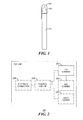
FIG. 1 is a front elevational view in accordance with the disclosure. -
FIG. 2 is a block diagram in accordance with the disclosure. -
FIG. 3 is a perspective view in accordance with the disclosure. -
FIG. 4 is a side elevational view in accordance with the disclosure. -
FIG. 5 is a perspective view in accordance with the disclosure. - The following describes an apparatus pertaining to a stylus pen cap having at least one camera disposed at least partially within the stylus pen cap. A corresponding stylus can have its writing tip snuggly stored within the stylus pen cap during periods of nonuse. During use, the stylus is removed from the stylus pen cap. The stylus pen cap can then be positioned to place the stylus within the field of view of the aforementioned camera. Captured images of the stylus, in turn, can be utilized to facilitate tracking at least a portion of the stylus (such as the writing tip) and using that tracking information as input to, for example, a corresponding display.
- By one approach the pen cap can include at least two such cameras. The use of a plurality of cameras can sometimes better facilitate the aforementioned tracking of the stylus. If desired, the pen cap can further include a light source (such as an infrared light source) that directs light outwardly of the pen cap and into the aforementioned field of view to thereby illuminate the stylus. Illuminating the stylus in this way can facilitate, for example, capturing the aforementioned images of the stylus during use.
- By one approach the pen cap can further include an electrical connector. This electrical connector can be operably coupled to the camera(s) and can be configured to convey captured-image data to an outboard device of choice such as a so-called smartphone, a tablet/pad-styled computer, a laptop computer, and so forth. If desired, the pen cap can include a pocket clip that comprises the electronic connector. By one approach the pocket clip can include a flexible joint (such as but not limited to a universal joint) to thereby permit, for example, the camera(s) to be oriented and aimed as desired even while electrically connected to an outboard device.
- Such a pen cap can be utilized with a variety of styli including both passive styli as well as active styli. By one approach the writing tip of the stylus can even comprise an ink-dispensing tip (such as a ball point pen tip). Accordingly, the stylus can be a relatively simple and inexpensive component if desired.
- So configured, the user is not constrained to using only a given display surface or other specialized scribing surface. Instead, virtually any surface can serve as a scribing surface including a sheet of paper. The pen cap itself, in turn, can serve as a camera platform that simply passes along its captured images or can, if desired, include its own circuitry and processing capabilities to, for example, analyze the captured images and extract corresponding location/tracking data as regards the stylus.
- The teachings are highly flexible in practice and are also highly scalable in that these teachings will accommodate any number (and type) of cameras and virtually any type, size, and shape of stylus. The installation and use of such a pen cap-based stylus tracking system can also be a relatively simple process that requires little user training to effect successfully.
- For simplicity and clarity of illustration, reference numerals may be repeated among the figures to indicate corresponding or analogous elements. Numerous details are set forth to provide an understanding of the embodiments described herein. The embodiments may be practiced without these details. In other instances, well-known methods, procedures, and components have not been described in detail to avoid obscuring the embodiments described. The description is not to be considered as limited to the scope of the embodiments described herein.
-
FIG. 1 presents apen cap 100 that snuggly receives one end (such as the writing tip 102) of astylus 101. Pen caps in general are well known in the art and the present teachings are not particularly limited in these regards. Generally speaking, the fit of a pen cap to a stylus is "snug" in that the pen cap will remain in place on the stylus through friction. This friction can be owing to a tight conformal fit between some part of the exterior of the stylus and the interior of the pen cap and/or due to a snap fit mechanism of choice. These teachings will also accommodate using a threaded connection (or any other connection mechanism) to temporarily (during non-use) retain the stylus portion within thepen cap 100. Thepen cap 100 can be formed of one or more materials of choice with plastic and/or metal being particularly useful for many application settings. - By one approach the
writing tip 102 can comprise a sharply pointed extension of the material that comprises thestylus 101 itself. By another approach thewriting tip 102 can be somewhat blunted to provide a larger point of contact with the scribing surface. And by yet another approach these teachings will accommodate having thewriting tip 102 comprise, at least in part, a ball point pen tip such that thestylus 101 is able to write on an appropriate surface (such as paper) using ink. - Both the
pen cap 100 and thestylus 101 can have any of a wide variety of form factors. As the present teachings are not particularly sensitive to any particular choices in these regards, for the sake of brevity further elaboration in these regards is not presented here. It will be noted, however, that the stylus/pen cap can be further configured to permit thepen cap 100 to also fit snuggly on the opposite end of thestylus 101 if desired. Thestylus 101 can also be configured to feature a writing tip at each of its ends if desired. - Referring to
FIG. 2 , thepen cap 100 can include one or more active components. For example, thepen cap 100 can include at least onecamera 201 disposed at least partially therein. Generally speaking, the lens (not shown in this figure) for thecamera 201 will typically be positioned in or somewhat above or below a corresponding cavity through an exterior wall of thepen cap 100. So configured, thecamera 201 can capture images of things and events that are external to thepen cap 100. Generally speaking, an image-capture rate of about thirty frames per second, for example, will serve well for these purposes. - As noted above the
pen cap 100 can include more than one such camera such as a second camera.FIG. 2 illustrates this approach by inclusion of an optional Nth camera 202 (where "N" comprises an integer greater than "1"). When using multiple cameras these teachings will accommodate using cameras that are essentially identical to one another. These teachings will also accommodate, however, using one or more cameras that are different from another of the cameras. This difference may pertain, for example, to pixel resolution, specific light sensitivities, aperture settings, fields of view, focal lengths, and so forth as desired. - By one approach the
pen cap 100 can further optionally include one or morelight sources 203 that are disposed at least partially therein. Such a light source can be configured to direct light outwardly of thepen cap 100 and into a field of view of one or more of theaforementioned cameras stylus 101 during use to facilitate capturing useful images of thestylus 101 via thecameras 201/202. - Such a
light source 203 can comprise any of a variety of light-emitting components. For many application settings a light-emitting diode will suffice in these regards. These teachings will also accommodate usinglight sources 203 that emit light at any of a variety of frequencies. For example, in many application settings it can be useful to employ light sources that comprise infrared light sources (presuming, of course, that one or more of thecameras stylus 101 in an outdoors setting during the daytime. - If desired, the
pen cap 100 can also include anoptional control circuit 204. Such acontrol circuit 204 can comprise a fixed-purpose hard-wired platform or can comprise a partially or wholly programmable platform. These architectural options are well known and understood in the art and require no further description here. Thiscontrol circuit 204 can be configured (via, for example, corresponding programming as will be well understood by those skilled in the art) to digitally transcribe movement of thestylus 101 relative to thepen cap 100 based upon images of thestylus 101 that are captured by the one ormore cameras pen cap 100. - Such a
control circuit 204 can comprise, in part, a corresponding digital memory if desired. This memory can serve, for example, to non-transitorily store the computer instructions that, when executed by thecontrol circuit 204, cause thecontrol circuit 204 to behave as described herein. (As used herein, this reference to "non-transitorily" will be understood to refer to a non-ephemeral state for the stored contents (and hence excludes when the stored contents merely constitute signals or waves) rather than volatility of the storage media itself and hence includes both non-volatile memory (such as read-only memory (ROM) as well as volatile memory (such as an erasable programmable read-only memory (EPROM).) - With continued reference to
FIG. 2 , thispen cap 100 can also further include an optionalelectrical connector 205. Thiselectrical connector 205 is operably coupled to one or more of thecameras 201 and 202 (via, for example, the aforementioned control circuit 204) and is configured to convey image data captured by thosecameras 201 and 202 (and/or other processed tracking/movement information when available) to a corresponding off-board device (not shown). - There are numerous electrical connectors known in the art and these teachings are not overly sensitive to any particular selections in these regards. For many application settings it can be useful if the
electrical connector 205 comprises a Universal Serial Bus (USB)-compatible electrical connector as are known in the art. This can include, without intending to suggest any particular limitations in these regards, a micro-USB connector or a micro-High-Definition Multimedia Interface (HDMI). - Referring to
FIG. 3 thepen cap 100 can further include, if desired, apocket clip 301. Pocket clips as comprise a part of a pen cap are well known in the art and typically serve to captivate pocket-forming fabric between itself and thestylus 101 when the latter is disposed within a user's shirt pocket (not shown). Accordingly, thispocket clip 301 extends downwardly below the lower periphery of thepen cap 100 and can also include a corresponding outboard portion on the side of thepen cap 100. - By one approach, and as illustrated, the
aforementioned cameras light source 203 can be disposed at least partially within such apocket clip 301. Formany pen cap 100 form factors such an approach can be advantageous in that thepocket clip 301 may offer a larger space to house such components than apen cap 100 that lacks such a clip. - If desired, this
pocket clip 301 can also comprise the aforementionedelectrical connector 205. In particular, by one approach theelectrical connector 205 can extend outwardly of theend portion 302 of thepocket clip 301. - If desired, and as illustrated, the
pocket clip 301 can include a flexible joint 303 to thereby permit theelectrical connector 205 to be flexibly positioned with respect to thepen cap 100. The present teachings will accommodate any of a wide variety of flexible joints including joints that permit only some limited amount of movement freedom with respect to a single axis of freedom to universal joints that will permit theend portion 302 of the pocket clip 301 (and hence the electrical connector 205) to be moved ninety degrees or more in essentially any direction and angle. - Whether the portion of the
pen cap 100 that houses one or more of the camera(s) 201 and 202, thelight source 203, and theelectrical connector 205 is in fact a "pocket clip" can vary as desired. As one illustrative example in these regards,FIG. 4 depicts apen cap 100 having a workingpocket clip 401 that is separate and apart from the so-calledpocket clip 301 that includes the foregoing components as described above with respect toFIG. 3 . - So configured, such a
pen cap 100 can remain installed on the end of acorresponding stylus 101 until a time of need. With reference toFIG. 5 , when needed, the user can remove thepen cap 100 from thestylus 101 and insert the electrical connector (205, not shown inFIG. 5 ) into a corresponding connector on an outboard device of choice such as the illustratedlaptop computer 501. - The upper portion of the
pocket clip 301 can then be manipulated with respect to the end portion 302 (via a flexible joint 303 that comprises, in this example, a schematically-represented universal joint) to aim thecameras 201 and 202 (as well as the light source 203) towards thestylus 101 in order to capture corresponding images that can be used to track the movement of the stylus 101 (and in particular thewriting tip 102 thereof). It will be appreciated that these teachings will permit the cameras (when thepen cap 100 includes more than one camera) to be selectively oriented horizontally to one another (as illustrated), vertically to one another, or at some other angle of choice. Such flexibility can help to accommodate the specific image requirements of various stylus-tracking algorithms. - There are various approaches and methodologies known in the art to employ a series of captured images of a moving object such as a stylus in order to develop information that follows the movement of at least a portion of that object (such as the object's writing tip). The present teachings are not particularly sensitive to the selection of any given such approach.
- So configured, a stylus movement-detector can be readily provided and made available for convenient use with a stylus at a time of need. Since at least some elements of such a detector comprise an integral part of the pen cap that the user employs to protect and/or store or carry the stylus, the user will typically have that detector available wherever and whenever the user wishes to use the stylus to enter scribed information into a corresponding platform such as a laptop or tablet/pad-styled computer. This availability and convenience, in turn, can greatly facilitate the user's successful employment of the stylus in these regards and can therefore contribute to increased user satisfaction.
- The present disclosure may be embodied in other specific forms without departing from its essential characteristics. The described embodiments are to be considered in all respects only as illustrative and not restrictive. The scope of the disclosure is, therefore, indicated by the appended claims rather than by the foregoing description. All changes that come within the meaning and range of equivalency of the claims are to be embraced within their scope.
Claims (15)
- An apparatus comprising:a pen cap (100);at least one camera (201) disposed at least partially within the pen cap.
- The apparatus of claim 1 further comprising:at least a second camera (202) disposed at least partially within the pen cap.
- The apparatus of claim 1 further comprising:a light source (203) disposed at least partially within the pen cap.
- The apparatus of claim 3 wherein the light source comprises an infrared light source.
- The apparatus of claim 3 wherein the light source is configured to direct light outwardly of the pen cap and into a field of view of the at least one camera.
- The apparatus of claim 1 further comprising:an electrical connector (205) operably coupled to the at least one camera and configured to convey image data captured by the at least one camera.
- The apparatus of claim 6 wherein the electrical connector comprises a Universal Serial Bus (USB)-compatible electrical connector.
- The apparatus of claim 6 wherein the electrical connector connects via a flexible joint (303) to the pen cap.
- The apparatus of claim 8 wherein the flexible joint comprises a universal joint.
- The apparatus of claim 6 wherein the pen cap includes a pocket clip (301) and wherein the pocket clip comprises the electrical connector.
- The apparatus of claim 10 wherein the pen cap further includes at least a second pocket clip (401).
- The apparatus of claim 1 further comprising:a pen (101) having at least one end thereof configured to store snuggly within the pen cap.
- The apparatus of claim 12 wherein the one end comprises a writing tip (102).
- The apparatus of claim 13 wherein the writing tip includes, at least in part, a ball point pen tip.
- The apparatus of claim 12 further comprising:a control circuit (204) configured to digitally transcribe movement of a stylus relative to the pen cap based upon images of the stylus that are captured by the at least one camera.
Priority Applications (1)
| Application Number | Priority Date | Filing Date | Title |
|---|---|---|---|
| EP12187168.5A EP2717122B1 (en) | 2012-10-04 | 2012-10-04 | Camera-equipped stylus pen cap |
Applications Claiming Priority (1)
| Application Number | Priority Date | Filing Date | Title |
|---|---|---|---|
| EP12187168.5A EP2717122B1 (en) | 2012-10-04 | 2012-10-04 | Camera-equipped stylus pen cap |
Publications (2)
| Publication Number | Publication Date |
|---|---|
| EP2717122A1 true EP2717122A1 (en) | 2014-04-09 |
| EP2717122B1 EP2717122B1 (en) | 2018-12-05 |
Family
ID=47010323
Family Applications (1)
| Application Number | Title | Priority Date | Filing Date |
|---|---|---|---|
| EP12187168.5A Active EP2717122B1 (en) | 2012-10-04 | 2012-10-04 | Camera-equipped stylus pen cap |
Country Status (1)
| Country | Link |
|---|---|
| EP (1) | EP2717122B1 (en) |
Cited By (3)
| Publication number | Priority date | Publication date | Assignee | Title |
|---|---|---|---|---|
| EP3064368A1 (en) * | 2015-03-02 | 2016-09-07 | Esselte Leitz GmbH & Co. KG | Writing or input pen |
| EP3936982A1 (en) * | 2020-07-07 | 2022-01-12 | Société BIC | A writing instrument configured to be tracked and positioned in a space, and method thereof |
| CN114047368A (en) * | 2022-01-10 | 2022-02-15 | 苏州威达智电子科技有限公司 | Automatic fine-adjustment full-function detection equipment and detection method thereof |
Citations (4)
| Publication number | Priority date | Publication date | Assignee | Title |
|---|---|---|---|---|
| WO2001031570A2 (en) * | 1999-10-27 | 2001-05-03 | Digital Ink, Inc. | Tracking motion of a writing instrument |
| US20040109722A1 (en) * | 2002-12-09 | 2004-06-10 | Huang Yea Yen | Connecting hub assembly having universal joint |
| US7401992B1 (en) * | 2007-05-09 | 2008-07-22 | Wei-Jong Lin | Writing instrument |
| EP1967386A1 (en) * | 2007-03-05 | 2008-09-10 | Berthold Löffler | Writing device with a clip |
Family Cites Families (1)
| Publication number | Priority date | Publication date | Assignee | Title |
|---|---|---|---|---|
| CN101303634B (en) * | 2007-05-09 | 2012-05-23 | 鸿富锦精密工业(深圳)有限公司 | Portable electronic apparatus |
-
2012
- 2012-10-04 EP EP12187168.5A patent/EP2717122B1/en active Active
Patent Citations (4)
| Publication number | Priority date | Publication date | Assignee | Title |
|---|---|---|---|---|
| WO2001031570A2 (en) * | 1999-10-27 | 2001-05-03 | Digital Ink, Inc. | Tracking motion of a writing instrument |
| US20040109722A1 (en) * | 2002-12-09 | 2004-06-10 | Huang Yea Yen | Connecting hub assembly having universal joint |
| EP1967386A1 (en) * | 2007-03-05 | 2008-09-10 | Berthold Löffler | Writing device with a clip |
| US7401992B1 (en) * | 2007-05-09 | 2008-07-22 | Wei-Jong Lin | Writing instrument |
Cited By (4)
| Publication number | Priority date | Publication date | Assignee | Title |
|---|---|---|---|---|
| EP3064368A1 (en) * | 2015-03-02 | 2016-09-07 | Esselte Leitz GmbH & Co. KG | Writing or input pen |
| EP3936982A1 (en) * | 2020-07-07 | 2022-01-12 | Société BIC | A writing instrument configured to be tracked and positioned in a space, and method thereof |
| WO2022008343A1 (en) * | 2020-07-07 | 2022-01-13 | Societe Bic | Writing instrument and method |
| CN114047368A (en) * | 2022-01-10 | 2022-02-15 | 苏州威达智电子科技有限公司 | Automatic fine-adjustment full-function detection equipment and detection method thereof |
Also Published As
| Publication number | Publication date |
|---|---|
| EP2717122B1 (en) | 2018-12-05 |
Similar Documents
| Publication | Publication Date | Title |
|---|---|---|
| US9096093B2 (en) | Camera-equipped stylus pen cap | |
| US10067568B2 (en) | Augmented reality writing system and method thereof | |
| EP3420437B1 (en) | Wireless positioning pen with pressure-sensitive tip | |
| CN107850968B (en) | Image display system | |
| US20110242348A1 (en) | Imaging apparatus, method of displaying, and program | |
| US20140002421A1 (en) | User interface device for projection computer and interface method using the same | |
| JP7086116B2 (en) | Electronic devices for analog stroke generation and digital recording of analog strokes, as well as input systems and methods for digitizing analog recordings. | |
| EP2927786B1 (en) | Interactive input system, interactive board and methods thereof | |
| EP2717122A1 (en) | Camera-equipped stylus pen cap | |
| CN103914679A (en) | Image identification method, device and electronic device | |
| US20190101754A1 (en) | Midair interaction with electronic pen projection computing system | |
| CN103538395A (en) | Track recording device | |
| JP2016509291A (en) | Method of assigning a pen-type handheld tool to a work object and / or detecting a change in the work object and both, and the pen-type handheld tool | |
| US20070146646A1 (en) | Digital annotation system and method | |
| US20230333677A1 (en) | Optical stylus for optical position determination device | |
| US20210142706A1 (en) | Mobile device with transparent display and scanner | |
| CN108089732B (en) | Capacitance pen for demonstration and projection mobile phone | |
| US9170685B2 (en) | Object location determination | |
| KR102261530B1 (en) | Handwriting input device | |
| CN113641256A (en) | Writing device capable of recognizing writing angle and method for recognizing writing angle | |
| KR101804796B1 (en) | Smart Input Apparatus | |
| EP2716468A1 (en) | Stylus body having two or more spheres coaxially affixed thereto | |
| CN101853098A (en) | Video projection system and method thereof | |
| WO2021208260A1 (en) | Method and device for displaying tracking frame of target object, and handheld camera | |
| CN105516558A (en) | Mobile terminal and image photographing method |
Legal Events
| Date | Code | Title | Description |
|---|---|---|---|
| PUAI | Public reference made under article 153(3) epc to a published international application that has entered the european phase |
Free format text: ORIGINAL CODE: 0009012 |
|
| 17P | Request for examination filed |
Effective date: 20121004 |
|
| AK | Designated contracting states |
Kind code of ref document: A1 Designated state(s): AL AT BE BG CH CY CZ DE DK EE ES FI FR GB GR HR HU IE IS IT LI LT LU LV MC MK MT NL NO PL PT RO RS SE SI SK SM TR |
|
| AX | Request for extension of the european patent |
Extension state: BA ME |
|
| STAA | Information on the status of an ep patent application or granted ep patent |
Free format text: STATUS: EXAMINATION IS IN PROGRESS |
|
| 17Q | First examination report despatched |
Effective date: 20180313 |
|
| GRAP | Despatch of communication of intention to grant a patent |
Free format text: ORIGINAL CODE: EPIDOSNIGR1 |
|
| STAA | Information on the status of an ep patent application or granted ep patent |
Free format text: STATUS: GRANT OF PATENT IS INTENDED |
|
| RIC1 | Information provided on ipc code assigned before grant |
Ipc: B43K 29/08 20060101ALI20180508BHEP Ipc: B43K 29/00 20060101ALI20180508BHEP Ipc: G06F 3/0354 20130101ALI20180508BHEP Ipc: B43K 7/00 20060101ALI20180508BHEP Ipc: G06F 3/03 20060101AFI20180508BHEP Ipc: B43K 29/10 20060101ALI20180508BHEP Ipc: B43K 23/12 20060101ALI20180508BHEP Ipc: B43K 25/02 20060101ALI20180508BHEP |
|
| INTG | Intention to grant announced |
Effective date: 20180604 |
|
| GRAS | Grant fee paid |
Free format text: ORIGINAL CODE: EPIDOSNIGR3 |
|
| GRAA | (expected) grant |
Free format text: ORIGINAL CODE: 0009210 |
|
| GRAA | (expected) grant |
Free format text: ORIGINAL CODE: 0009210 |
|
| STAA | Information on the status of an ep patent application or granted ep patent |
Free format text: STATUS: THE PATENT HAS BEEN GRANTED |
|
| AK | Designated contracting states |
Kind code of ref document: B1 Designated state(s): AL AT BE BG CH CY CZ DE DK EE ES FI FR GB GR HR HU IE IS IT LI LT LU LV MC MK MT NL NO PL PT RO RS SE SI SK SM TR |
|
| REG | Reference to a national code |
Ref country code: GB Ref legal event code: FG4D |
|
| REG | Reference to a national code |
Ref country code: CH Ref legal event code: EP |
|
| REG | Reference to a national code |
Ref country code: AT Ref legal event code: REF Ref document number: 1073871 Country of ref document: AT Kind code of ref document: T Effective date: 20181215 |
|
| REG | Reference to a national code |
Ref country code: IE Ref legal event code: FG4D |
|
| REG | Reference to a national code |
Ref country code: DE Ref legal event code: R096 Ref document number: 602012054276 Country of ref document: DE |
|
| REG | Reference to a national code |
Ref country code: NL Ref legal event code: MP Effective date: 20181205 |
|
| REG | Reference to a national code |
Ref country code: AT Ref legal event code: MK05 Ref document number: 1073871 Country of ref document: AT Kind code of ref document: T Effective date: 20181205 |
|
| REG | Reference to a national code |
Ref country code: LT Ref legal event code: MG4D |
|
| PG25 | Lapsed in a contracting state [announced via postgrant information from national office to epo] |
Ref country code: AT Free format text: LAPSE BECAUSE OF FAILURE TO SUBMIT A TRANSLATION OF THE DESCRIPTION OR TO PAY THE FEE WITHIN THE PRESCRIBED TIME-LIMIT Effective date: 20181205 Ref country code: LV Free format text: LAPSE BECAUSE OF FAILURE TO SUBMIT A TRANSLATION OF THE DESCRIPTION OR TO PAY THE FEE WITHIN THE PRESCRIBED TIME-LIMIT Effective date: 20181205 Ref country code: HR Free format text: LAPSE BECAUSE OF FAILURE TO SUBMIT A TRANSLATION OF THE DESCRIPTION OR TO PAY THE FEE WITHIN THE PRESCRIBED TIME-LIMIT Effective date: 20181205 Ref country code: BG Free format text: LAPSE BECAUSE OF FAILURE TO SUBMIT A TRANSLATION OF THE DESCRIPTION OR TO PAY THE FEE WITHIN THE PRESCRIBED TIME-LIMIT Effective date: 20190305 Ref country code: NO Free format text: LAPSE BECAUSE OF FAILURE TO SUBMIT A TRANSLATION OF THE DESCRIPTION OR TO PAY THE FEE WITHIN THE PRESCRIBED TIME-LIMIT Effective date: 20190305 Ref country code: ES Free format text: LAPSE BECAUSE OF FAILURE TO SUBMIT A TRANSLATION OF THE DESCRIPTION OR TO PAY THE FEE WITHIN THE PRESCRIBED TIME-LIMIT Effective date: 20181205 Ref country code: LT Free format text: LAPSE BECAUSE OF FAILURE TO SUBMIT A TRANSLATION OF THE DESCRIPTION OR TO PAY THE FEE WITHIN THE PRESCRIBED TIME-LIMIT Effective date: 20181205 Ref country code: FI Free format text: LAPSE BECAUSE OF FAILURE TO SUBMIT A TRANSLATION OF THE DESCRIPTION OR TO PAY THE FEE WITHIN THE PRESCRIBED TIME-LIMIT Effective date: 20181205 |
|
| PG25 | Lapsed in a contracting state [announced via postgrant information from national office to epo] |
Ref country code: GR Free format text: LAPSE BECAUSE OF FAILURE TO SUBMIT A TRANSLATION OF THE DESCRIPTION OR TO PAY THE FEE WITHIN THE PRESCRIBED TIME-LIMIT Effective date: 20190306 Ref country code: RS Free format text: LAPSE BECAUSE OF FAILURE TO SUBMIT A TRANSLATION OF THE DESCRIPTION OR TO PAY THE FEE WITHIN THE PRESCRIBED TIME-LIMIT Effective date: 20181205 Ref country code: SE Free format text: LAPSE BECAUSE OF FAILURE TO SUBMIT A TRANSLATION OF THE DESCRIPTION OR TO PAY THE FEE WITHIN THE PRESCRIBED TIME-LIMIT Effective date: 20181205 Ref country code: AL Free format text: LAPSE BECAUSE OF FAILURE TO SUBMIT A TRANSLATION OF THE DESCRIPTION OR TO PAY THE FEE WITHIN THE PRESCRIBED TIME-LIMIT Effective date: 20181205 |
|
| PG25 | Lapsed in a contracting state [announced via postgrant information from national office to epo] |
Ref country code: NL Free format text: LAPSE BECAUSE OF FAILURE TO SUBMIT A TRANSLATION OF THE DESCRIPTION OR TO PAY THE FEE WITHIN THE PRESCRIBED TIME-LIMIT Effective date: 20181205 |
|
| PG25 | Lapsed in a contracting state [announced via postgrant information from national office to epo] |
Ref country code: PL Free format text: LAPSE BECAUSE OF FAILURE TO SUBMIT A TRANSLATION OF THE DESCRIPTION OR TO PAY THE FEE WITHIN THE PRESCRIBED TIME-LIMIT Effective date: 20181205 Ref country code: IT Free format text: LAPSE BECAUSE OF FAILURE TO SUBMIT A TRANSLATION OF THE DESCRIPTION OR TO PAY THE FEE WITHIN THE PRESCRIBED TIME-LIMIT Effective date: 20181205 Ref country code: PT Free format text: LAPSE BECAUSE OF FAILURE TO SUBMIT A TRANSLATION OF THE DESCRIPTION OR TO PAY THE FEE WITHIN THE PRESCRIBED TIME-LIMIT Effective date: 20190405 Ref country code: CZ Free format text: LAPSE BECAUSE OF FAILURE TO SUBMIT A TRANSLATION OF THE DESCRIPTION OR TO PAY THE FEE WITHIN THE PRESCRIBED TIME-LIMIT Effective date: 20181205 |
|
| PG25 | Lapsed in a contracting state [announced via postgrant information from national office to epo] |
Ref country code: IS Free format text: LAPSE BECAUSE OF FAILURE TO SUBMIT A TRANSLATION OF THE DESCRIPTION OR TO PAY THE FEE WITHIN THE PRESCRIBED TIME-LIMIT Effective date: 20190405 Ref country code: RO Free format text: LAPSE BECAUSE OF FAILURE TO SUBMIT A TRANSLATION OF THE DESCRIPTION OR TO PAY THE FEE WITHIN THE PRESCRIBED TIME-LIMIT Effective date: 20181205 Ref country code: SM Free format text: LAPSE BECAUSE OF FAILURE TO SUBMIT A TRANSLATION OF THE DESCRIPTION OR TO PAY THE FEE WITHIN THE PRESCRIBED TIME-LIMIT Effective date: 20181205 Ref country code: EE Free format text: LAPSE BECAUSE OF FAILURE TO SUBMIT A TRANSLATION OF THE DESCRIPTION OR TO PAY THE FEE WITHIN THE PRESCRIBED TIME-LIMIT Effective date: 20181205 Ref country code: SK Free format text: LAPSE BECAUSE OF FAILURE TO SUBMIT A TRANSLATION OF THE DESCRIPTION OR TO PAY THE FEE WITHIN THE PRESCRIBED TIME-LIMIT Effective date: 20181205 |
|
| REG | Reference to a national code |
Ref country code: DE Ref legal event code: R097 Ref document number: 602012054276 Country of ref document: DE |
|
| PLBE | No opposition filed within time limit |
Free format text: ORIGINAL CODE: 0009261 |
|
| STAA | Information on the status of an ep patent application or granted ep patent |
Free format text: STATUS: NO OPPOSITION FILED WITHIN TIME LIMIT |
|
| PG25 | Lapsed in a contracting state [announced via postgrant information from national office to epo] |
Ref country code: SI Free format text: LAPSE BECAUSE OF FAILURE TO SUBMIT A TRANSLATION OF THE DESCRIPTION OR TO PAY THE FEE WITHIN THE PRESCRIBED TIME-LIMIT Effective date: 20181205 Ref country code: DK Free format text: LAPSE BECAUSE OF FAILURE TO SUBMIT A TRANSLATION OF THE DESCRIPTION OR TO PAY THE FEE WITHIN THE PRESCRIBED TIME-LIMIT Effective date: 20181205 |
|
| 26N | No opposition filed |
Effective date: 20190906 |
|
| PG25 | Lapsed in a contracting state [announced via postgrant information from national office to epo] |
Ref country code: TR Free format text: LAPSE BECAUSE OF FAILURE TO SUBMIT A TRANSLATION OF THE DESCRIPTION OR TO PAY THE FEE WITHIN THE PRESCRIBED TIME-LIMIT Effective date: 20181205 |
|
| PG25 | Lapsed in a contracting state [announced via postgrant information from national office to epo] |
Ref country code: MC Free format text: LAPSE BECAUSE OF FAILURE TO SUBMIT A TRANSLATION OF THE DESCRIPTION OR TO PAY THE FEE WITHIN THE PRESCRIBED TIME-LIMIT Effective date: 20181205 |
|
| REG | Reference to a national code |
Ref country code: CH Ref legal event code: PL |
|
| PG25 | Lapsed in a contracting state [announced via postgrant information from national office to epo] |
Ref country code: LU Free format text: LAPSE BECAUSE OF NON-PAYMENT OF DUE FEES Effective date: 20191004 Ref country code: CH Free format text: LAPSE BECAUSE OF NON-PAYMENT OF DUE FEES Effective date: 20191031 Ref country code: LI Free format text: LAPSE BECAUSE OF NON-PAYMENT OF DUE FEES Effective date: 20191031 |
|
| REG | Reference to a national code |
Ref country code: BE Ref legal event code: MM Effective date: 20191031 |
|
| PG25 | Lapsed in a contracting state [announced via postgrant information from national office to epo] |
Ref country code: BE Free format text: LAPSE BECAUSE OF NON-PAYMENT OF DUE FEES Effective date: 20191031 |
|
| PG25 | Lapsed in a contracting state [announced via postgrant information from national office to epo] |
Ref country code: IE Free format text: LAPSE BECAUSE OF NON-PAYMENT OF DUE FEES Effective date: 20191004 |
|
| PG25 | Lapsed in a contracting state [announced via postgrant information from national office to epo] |
Ref country code: CY Free format text: LAPSE BECAUSE OF FAILURE TO SUBMIT A TRANSLATION OF THE DESCRIPTION OR TO PAY THE FEE WITHIN THE PRESCRIBED TIME-LIMIT Effective date: 20181205 |
|
| PG25 | Lapsed in a contracting state [announced via postgrant information from national office to epo] |
Ref country code: HU Free format text: LAPSE BECAUSE OF FAILURE TO SUBMIT A TRANSLATION OF THE DESCRIPTION OR TO PAY THE FEE WITHIN THE PRESCRIBED TIME-LIMIT; INVALID AB INITIO Effective date: 20121004 Ref country code: MT Free format text: LAPSE BECAUSE OF FAILURE TO SUBMIT A TRANSLATION OF THE DESCRIPTION OR TO PAY THE FEE WITHIN THE PRESCRIBED TIME-LIMIT Effective date: 20181205 |
|
| PG25 | Lapsed in a contracting state [announced via postgrant information from national office to epo] |
Ref country code: MK Free format text: LAPSE BECAUSE OF FAILURE TO SUBMIT A TRANSLATION OF THE DESCRIPTION OR TO PAY THE FEE WITHIN THE PRESCRIBED TIME-LIMIT Effective date: 20181205 |
|
| PGFP | Annual fee paid to national office [announced via postgrant information from national office to epo] |
Ref country code: GB Payment date: 20231027 Year of fee payment: 12 |
|
| PGFP | Annual fee paid to national office [announced via postgrant information from national office to epo] |
Ref country code: FR Payment date: 20231025 Year of fee payment: 12 Ref country code: DE Payment date: 20231027 Year of fee payment: 12 |