EP2717112A1 - Pedal arm bearing member, pedal arm, and method for manufacturing pedal arm - Google Patents
Pedal arm bearing member, pedal arm, and method for manufacturing pedal arm Download PDFInfo
- Publication number
- EP2717112A1 EP2717112A1 EP11866926.6A EP11866926A EP2717112A1 EP 2717112 A1 EP2717112 A1 EP 2717112A1 EP 11866926 A EP11866926 A EP 11866926A EP 2717112 A1 EP2717112 A1 EP 2717112A1
- Authority
- EP
- European Patent Office
- Prior art keywords
- mounting hole
- connecting portion
- bearing member
- pair
- pedal arm
- Prior art date
- Legal status (The legal status is an assumption and is not a legal conclusion. Google has not performed a legal analysis and makes no representation as to the accuracy of the status listed.)
- Granted
Links
- 238000000034 method Methods 0.000 title claims abstract description 13
- 238000004519 manufacturing process Methods 0.000 title claims description 8
- 230000002093 peripheral effect Effects 0.000 claims abstract description 64
- 238000003466 welding Methods 0.000 claims description 18
- 238000007906 compression Methods 0.000 claims description 13
- 230000006835 compression Effects 0.000 claims description 11
- 230000004323 axial length Effects 0.000 claims description 9
- 230000005540 biological transmission Effects 0.000 description 3
- 230000000694 effects Effects 0.000 description 3
- 238000003825 pressing Methods 0.000 description 3
- 230000006872 improvement Effects 0.000 description 2
- 230000008569 process Effects 0.000 description 2
- 229910000831 Steel Inorganic materials 0.000 description 1
- 230000008859 change Effects 0.000 description 1
- 239000002184 metal Substances 0.000 description 1
- 238000012986 modification Methods 0.000 description 1
- 230000004048 modification Effects 0.000 description 1
- 230000000717 retained effect Effects 0.000 description 1
- 239000010959 steel Substances 0.000 description 1
Images



Classifications
-
- G—PHYSICS
- G05—CONTROLLING; REGULATING
- G05G—CONTROL DEVICES OR SYSTEMS INSOFAR AS CHARACTERISED BY MECHANICAL FEATURES ONLY
- G05G1/00—Controlling members, e.g. knobs or handles; Assemblies or arrangements thereof; Indicating position of controlling members
- G05G1/30—Controlling members actuated by foot
- G05G1/44—Controlling members actuated by foot pivoting
-
- F—MECHANICAL ENGINEERING; LIGHTING; HEATING; WEAPONS; BLASTING
- F16—ENGINEERING ELEMENTS AND UNITS; GENERAL MEASURES FOR PRODUCING AND MAINTAINING EFFECTIVE FUNCTIONING OF MACHINES OR INSTALLATIONS; THERMAL INSULATION IN GENERAL
- F16C—SHAFTS; FLEXIBLE SHAFTS; ELEMENTS OR CRANKSHAFT MECHANISMS; ROTARY BODIES OTHER THAN GEARING ELEMENTS; BEARINGS
- F16C11/00—Pivots; Pivotal connections
- F16C11/04—Pivotal connections
- F16C11/045—Pivotal connections with at least a pair of arms pivoting relatively to at least one other arm, all arms being mounted on one pin
-
- F—MECHANICAL ENGINEERING; LIGHTING; HEATING; WEAPONS; BLASTING
- F16—ENGINEERING ELEMENTS AND UNITS; GENERAL MEASURES FOR PRODUCING AND MAINTAINING EFFECTIVE FUNCTIONING OF MACHINES OR INSTALLATIONS; THERMAL INSULATION IN GENERAL
- F16C—SHAFTS; FLEXIBLE SHAFTS; ELEMENTS OR CRANKSHAFT MECHANISMS; ROTARY BODIES OTHER THAN GEARING ELEMENTS; BEARINGS
- F16C33/00—Parts of bearings; Special methods for making bearings or parts thereof
- F16C33/02—Parts of sliding-contact bearings
- F16C33/04—Brasses; Bushes; Linings
- F16C33/06—Sliding surface mainly made of metal
- F16C33/08—Attachment of brasses, bushes or linings to the bearing housing
-
- G—PHYSICS
- G05—CONTROLLING; REGULATING
- G05G—CONTROL DEVICES OR SYSTEMS INSOFAR AS CHARACTERISED BY MECHANICAL FEATURES ONLY
- G05G1/00—Controlling members, e.g. knobs or handles; Assemblies or arrangements thereof; Indicating position of controlling members
- G05G1/30—Controlling members actuated by foot
- G05G1/50—Manufacturing of pedals; Pedals characterised by the material used
-
- G—PHYSICS
- G05—CONTROLLING; REGULATING
- G05G—CONTROL DEVICES OR SYSTEMS INSOFAR AS CHARACTERISED BY MECHANICAL FEATURES ONLY
- G05G1/00—Controlling members, e.g. knobs or handles; Assemblies or arrangements thereof; Indicating position of controlling members
- G05G1/30—Controlling members actuated by foot
- G05G1/50—Manufacturing of pedals; Pedals characterised by the material used
- G05G1/506—Controlling members for foot-actuation
-
- F—MECHANICAL ENGINEERING; LIGHTING; HEATING; WEAPONS; BLASTING
- F16—ENGINEERING ELEMENTS AND UNITS; GENERAL MEASURES FOR PRODUCING AND MAINTAINING EFFECTIVE FUNCTIONING OF MACHINES OR INSTALLATIONS; THERMAL INSULATION IN GENERAL
- F16C—SHAFTS; FLEXIBLE SHAFTS; ELEMENTS OR CRANKSHAFT MECHANISMS; ROTARY BODIES OTHER THAN GEARING ELEMENTS; BEARINGS
- F16C2226/00—Joining parts; Fastening; Assembling or mounting parts
- F16C2226/50—Positive connections
- F16C2226/52—Positive connections with plastic deformation, e.g. caulking or staking
-
- F—MECHANICAL ENGINEERING; LIGHTING; HEATING; WEAPONS; BLASTING
- F16—ENGINEERING ELEMENTS AND UNITS; GENERAL MEASURES FOR PRODUCING AND MAINTAINING EFFECTIVE FUNCTIONING OF MACHINES OR INSTALLATIONS; THERMAL INSULATION IN GENERAL
- F16C—SHAFTS; FLEXIBLE SHAFTS; ELEMENTS OR CRANKSHAFT MECHANISMS; ROTARY BODIES OTHER THAN GEARING ELEMENTS; BEARINGS
- F16C2326/00—Articles relating to transporting
- F16C2326/01—Parts of vehicles in general
-
- F—MECHANICAL ENGINEERING; LIGHTING; HEATING; WEAPONS; BLASTING
- F16—ENGINEERING ELEMENTS AND UNITS; GENERAL MEASURES FOR PRODUCING AND MAINTAINING EFFECTIVE FUNCTIONING OF MACHINES OR INSTALLATIONS; THERMAL INSULATION IN GENERAL
- F16C—SHAFTS; FLEXIBLE SHAFTS; ELEMENTS OR CRANKSHAFT MECHANISMS; ROTARY BODIES OTHER THAN GEARING ELEMENTS; BEARINGS
- F16C35/00—Rigid support of bearing units; Housings, e.g. caps, covers
- F16C35/02—Rigid support of bearing units; Housings, e.g. caps, covers in the case of sliding-contact bearings
-
- G—PHYSICS
- G05—CONTROLLING; REGULATING
- G05G—CONTROL DEVICES OR SYSTEMS INSOFAR AS CHARACTERISED BY MECHANICAL FEATURES ONLY
- G05G1/00—Controlling members, e.g. knobs or handles; Assemblies or arrangements thereof; Indicating position of controlling members
- G05G1/30—Controlling members actuated by foot
- G05G1/46—Means, e.g. links, for connecting the pedal to the controlled unit
-
- Y—GENERAL TAGGING OF NEW TECHNOLOGICAL DEVELOPMENTS; GENERAL TAGGING OF CROSS-SECTIONAL TECHNOLOGIES SPANNING OVER SEVERAL SECTIONS OF THE IPC; TECHNICAL SUBJECTS COVERED BY FORMER USPC CROSS-REFERENCE ART COLLECTIONS [XRACs] AND DIGESTS
- Y10—TECHNICAL SUBJECTS COVERED BY FORMER USPC
- Y10T—TECHNICAL SUBJECTS COVERED BY FORMER US CLASSIFICATION
- Y10T29/00—Metal working
- Y10T29/49—Method of mechanical manufacture
- Y10T29/49826—Assembling or joining
- Y10T29/49908—Joining by deforming
- Y10T29/49938—Radially expanding part in cavity, aperture, or hollow body
- Y10T29/4994—Radially expanding internal tube
-
- Y—GENERAL TAGGING OF NEW TECHNOLOGICAL DEVELOPMENTS; GENERAL TAGGING OF CROSS-SECTIONAL TECHNOLOGIES SPANNING OVER SEVERAL SECTIONS OF THE IPC; TECHNICAL SUBJECTS COVERED BY FORMER USPC CROSS-REFERENCE ART COLLECTIONS [XRACs] AND DIGESTS
- Y10—TECHNICAL SUBJECTS COVERED BY FORMER USPC
- Y10T—TECHNICAL SUBJECTS COVERED BY FORMER US CLASSIFICATION
- Y10T74/00—Machine element or mechanism
- Y10T74/20—Control lever and linkage systems
- Y10T74/20528—Foot operated
Definitions
- the invention relates to a pedal arm, and more specifically to an improvement of a tubular bearing member which is disposed across a pair of plate members that constitute side walls of the pedal arm and through which a connecting shaft is passed so as to be rotatable relative to the bearing member.
- a bearing member is disposed in a plate member that constitutes the pedal arm.
- a pedal arm has a hollow structure formed of a pair of halves, the pair of halves respectively has connecting holes, and a clevis pin is passed through the connecting holes so as to be rotatable relative to the halves.
- a cylindrical bearing member is fixedly provided in the connecting hole of one of the halves.
- burring holes are respectively formed in the pair of halves, and a cylindrical boss is disposed so as to pass through the burring holes and is fixed to the burring holes by welding.
- Patent Document 2 describes a technique in which a bearing member is swaged to be fixed to a mounting hole formed in a plate member that constitutes a pedal arm, and a connecting shaft such as a support shaft is connected to the plate member via the bearing member so as to be rotatable relative to the plate member.
- the bearing member includes: (a) a large-diameter tubular portion which has an external diameter larger than the diameter of the mounting hole and through which the connecting shaft is passed so as to be rotatable relative to the large-diameter tubular portion, and (b) a connecting portion that has an external diameter smaller than the diameter of the mounting hole, that is formed coaxially with the large-diameter tubular portion so as to project from one end face of the large-diameter tubular portion, and that is passed through the mounting hole, wherein (c) when the connecting portion is compressed in the axial direction to be swaged (compressed), a peripheral portion of the mounting hole is held between a swaged portion, which is formed from the connecting portion, and the end face of the large-diameter tubular portion, whereby the bearing member is fixedly fitted to the mounting hole.
- Patent Document 2 may be applied to a pedal arm having a hollow structure formed by fitting a pair of plate members together, so that connecting portions are formed at respective ends of the large-diameter tubular portion and swaged to be respectively fixed to the pair of plate members.
- the pedal arm may be deformed by swaging.
- the invention is made in light of the above-described circumstances, and it is an object of the invention to provide a fixation technique which is implemented easily and at low cost, and with which a bearing member is appropriately fixed regardless of variations in the distance between a pair of plate members of a pedal arm when the bearing member is disposed across the pair of plate members such that insertability of a connecting shaft is secured.
- a bearing member for a pedal arm which is a tubular bearing member which is disposed so as to connect a first mounting hole and a second mounting hole formed respectively in a pair of plate members constituting right and left side walls of the pedal arm and through which a connecting shaft is passed so as to be rotatable relative to the bearing member
- the bearing member characterized by including: (a) a large-diameter tubular portion having an external diameter larger than a diameter of the first mounting hole and located between the pair of plate members; (b) a first connecting portion that has an external diameter smaller than the diameter of the first mounting hole, that is formed so as to project from one end face of the large-diameter tubular portion coaxially with the large-diameter tubular portion, that is passed through the first mounting hole, and that is fixedly fitted to the first mounting hole by being compressed in an axial direction to be swaged so that a peripheral portion of the first mounting hole is held between a swaged portion,
- the second aspect of the invention according to the bearing member for a pedal arm of the first aspect of the invention, characterized in that: (a) an axial length of the large-diameter tubular portion is set to be shorter than an allowable lower limit of a distance L between the pair of plate members so that the large-diameter tubular portion is interposed between the pair of plate members regardless of variation in the distance L; and (b) a projecting length of the second connecting portion from the other end face of the large-diameter tubular portion is set such that, regardless of variation in the distance L, the second connecting portion is passed through the second mounting hole and is bulged and deformed radially outward by being compressed in the axial direction so as to be brought into close contact with the inner peripheral wall of the second mounting hole.
- the fourth aspect of the invention is a method for manufacturing the pedal arm according to the third aspect of the invention, the method characterized by including: a welding step of integrally welding the peripheral portions of the pair of halves in a state where the bearing member is disposed so as to locate the large-diameter tubular portion between the pair of halves, so that the first connecting portion is passed through the first mounting hole and the second connecting portion is passed through the second mounting hole; and a compression step of fixedly fitting the first connecting portion to the first mounting hole by swaging the first connecting portion, and fixedly fitting the second connecting portion to the second mounting hole by bulging and deforming the second connecting portion radially outward, in a series of compression processes in which the bearing member is compressed in the axial direction after the pair of halves are welded, and a compression load is increased.
- the bearing member of the pedal arm according to the first aspect of the invention is disposed so as to connect the pair of plate members constituting the right and left side walls of the pedal arm, it is possible to easily and appropriately connect the connecting shaft to the pedal arm by passing the connecting shaft through the bearing member . As a result, the efficiency of load transmission between the pedal arm and the connecting shaft is secured sufficiently. Further, when the first connecting portion that is connected to the first mounting hole is swaged by being compressed in the axial direction, the first connecting portion is fixedly fitted to the first mounting hole so that the peripheral portion of the first mounting hole is held between the swaged portion, which is formed from the first connecting portion, and the end face of the large-diameter tubular portion.
- the second connecting portion that is connected to the second mounting hole is bulged and deformed radially outward by being compressed in the axial direction, so that the portion of the second connecting portion, which is apart from the end face of the large-diameter tubular portion by the predetermined distance, is brought into close contact with the inner peripheral wall of the second mounting hole.
- the second connecting portion is fixedly fitted to the second mounting hole. Accordingly, even if the distance L between the pair of plate members varies, variation is absorbed by changing a fixed portion at which the second connecting portion is fixed to the second mounting hole. Therefore, it is possible to fix the bearing member without deforming the pedal arm.
- the second connecting portion is thicker than the first connecting portion, and in view of this, if a compressive load that is applied in the axial direction is increased gradually, the thin first connecting portion is swaged first and then the second connecting portion is bulged and deformed. Thus, it is possible to compress and deform the first connecting portion and the second connecting portion sequentially by a series of compression operations to fix them.
- the axial length of the large-diameter tubular portion is set to be shorter than the allowable lower limit of the distance L so that, regardless of variations in the distance L, the large-diameter tubular portion is interposed between the pair of plate members.
- the projecting length of the second connecting portion is set such that, regardless of variations in the distance L, the second connecting portion is passed through the second mounting hole and is then bulged and deformed radially outward by being compressed in the axial direction to be brought into close contact with the inner peripheral wall of the second mounting hole. This makes it possible to reliably fix the bearing member across the pair of plate members without deforming the pair of plate members regardless of variations in the distance L.
- a pedal arm having a hollow structure formed by integrally welding peripheral portions of a pair of plate-like halves having shapes obtained by dividing a shape of the pedal arm in a width direction, characterized in that: one of the pair of halves and the other one of the pair of halves have a first mounting hole and a second mounting hole, respectively; and the bearing member according to claim 1 or 2 is disposed so as to connect the first mounting hole to the second mounting hole.
- the fourth aspect of the invention is a method for manufacturing the pedal arm according to the third aspect of the invention, in a series of processes in which the peripheral portions of the pair of halves are integrally welded in a state where the bearing member is disposed such that the first connecting portion is passed through the first mounting hole and the second connecting portion is passed through the second mounting hole, and subsequently, the bearing member is compressed in the axial direction to increase the compressive load, the first connecting portion is swaged to be fixed to the first mounting hole and the second connecting portion is bulged and deformed radially outward to be fixed to the second mounting hole.
- the manufacturing cost is further reduced.
- the invention is suitably applied to, for example, a brake pedal, a clutch pedal, an accelerator pedal, and the like for vehicles, but may also be applied to operation pedals other than pedals for vehicles.
- the third and fourth inventions relate to the pedal arm having a hollow structure formed of a pair of halves (plate members).
- the hollow structure is not necessarily configured such that a whole circumference is sealed in a saclike form, but may be opened partially.
- the invention is suitably applied to a bearing member provided at a joint between a support shaft by which a pedal arm is pivotably supported and the pedal arm, a bearing member provided at a joint between a clevis pin that connects a pedal arm and a clevis such that the pedal arm and the clevis are rotatable relative to each other and the pedal arm, and the like.
- the external diameter of a large-diameter tubular portion of a bearing member should be larger than the diameter of a first mounting hole and the diameter of a first connecting portion, and the inner diameter of a second mounting hole and the external diameter of a second connecting portion may be either larger or smaller than the external diameter of the large-diameter tubular portion.
- the bearing member has a cylindrical support inner peripheral face along which a connecting shaft is extended so as to be rotatable relative to the support inner peripheral face.
- the support inner peripheral face be formed at the large-diameter tubular portion, and it is also preferable that inner diameters of the first connecting portion and the second connecting portion be set to be slightly larger than the diameter of the support inner peripheral face in consideration of a change in the inner diameter due to compressive deformation. That is, when the bearing member is compressed in an axial direction and receives a compressive load, compressive stress in a circumferential direction acts on inner peripheral side, so that the first connecting portion and second connecting portion are compressed and deformed so as to bulge mainly radially outward.
- a distal end portion of the first connecting portion is swaged radially outward so that a peripheral portion of the first mounting hole is held between the first connection portion and the end face of the large-diameter tubular portion, while the second connecting portion is bulged and deformed radially outward so as to be brought into close contact with an inner peripheral wall of the second mounting hole.
- the first and second connecting portions may also bulge radially inward to some extent due to deformation resistance or the like, and in view of this, the inner diameters of the first and second connecting portions are set so as not to be smaller than the diameter of the support inner peripheral face even if the first and second connecting portions bulge radially inward.
- the support inner peripheral face is a portion which is brought into sliding contact with an outer peripheral face of the connecting shaft, and the diameter of the support inner peripheral face is set to be slightly larger than the external diameter of the connecting shaft.
- the shape of the outer peripheral face of the large-diameter tubular portion is preferably cylindrical, but may be a polygonal column shape such as a square pole shape.
- the shapes of the inner and outer peripheral faces of the first connecting portion and the second connecting portion and the first mounting hole and the second mounting hole are also preferably cylindrical and a circular-hole shape, but a polygonal column shape or a polygonal hole may be employed, respectively.
- the pair of plate members which constitute right and left side walls of the pedal arm according to the first invention may be a pair of halves having shapes obtained by dividing the shape of the pedal arm in a width direction, as in the case of the pedal arm according to the third invention, or may be, for example, a pair of flat side plate members fixedly fitted together by a plurality of connecting pins or the like in a such a position that the side plate members are substantially parallel to each other across a predetermined distance.
- the axial length of the large-diameter tubular portion and the projecting length of the second connecting portion are set, for example, on the basis of an allowable lower limit and an allowable upper limit of a distance L between the pair of plate members.
- the axial length may be set with a sufficient margin so that the large-diameter tubular portion is interposed between the pair of plate members regardless of variations in the distance L
- the projecting length may be set with a sufficient margin so that the second connecting portion is bulged and deformed by being compressed in the axial direction so that the second connecting portion is brought into close contact with the inner peripheral wall of the second mounting hole.
- peripheral portions of the pair of halves are welded integrally in a state where the bearing member is disposed such that the first connecting portion is passed through the first mounting hole and the second connecting portion is passed through the second mounting hole, and after that, the bearing member is compressed in the axial direction so that the first connecting portion is swaged to be fixedly fitted to the first mounting hole while the second connecting portion is bulged and deformed radially outward to be fixedly fitted to the second mounting hole.
- swaging of the first connecting portion and bulging deformation of the second connecting portion may be performed in different steps.
- the bearing member is axially compressed with the first connecting portion passed through the first mounting hole, so that the first connecting portion is swaged to be fixedly fitted to the first mounting hole.
- the peripheral portions of the pair of halves are integrally welded with the second connecting portion passed through the second mounting hole, and then, the bearing member is compressed again in the axial direction, so that the second connecting portion is bulged and deformed radially outward to be fixedly fitted to the second mounting hole.
- FIG 1 illustrates views showing a brake pedal 10 for a service brake of a vehicle to which the invention is applied, wherein FIG 1(a) is a left side view, FIG 1(b) is an enlarged view of a section taken along the line IB-IB in FIG 1(a), and FIG 1(c) is an enlarged sectional view showing a portion IC in FIG. 1(b) .
- the brake pedal 10 has a pedal arm 14 as a main component.
- the brake pedal 10 is supported, at an upper end portion of the pedal arm 14, so as to be pivotable about a support axis O, which is an axis of a substantially horizontal support shaft 12.
- a lower end portion of the pedal arm 14 is bent diagonally upward in a direction toward the rear of the vehicle so as to be oriented toward a driver seat, and a pedal sheet 18 is fixedly fitted to the lower end portion of the pedal arm 14.
- the brake pedal 10 pivots clockwise about the support shaft 12 in FIG 1(a) .
- An output member 22 such as a pushrod is connected to the brake pedal 10 via a clevis 24 so as to be pivotable, relative to the brake pedal 10, about an axis of a clevis pin 20, which is substantially parallel to the support shaft 12.
- the output member 22 is mechanically pushed leftward in FIG 1(a) as the brake pedal 10 pivots, brake hydraulic pressure is generated on the basis of the depression force applied to the brake pedal 10.
- the clevis pin 20 corresponds to a connecting shaft.
- the pedal arm 14 has a hollow structure having a substantially quadrangular section, and is formed of a pair of halves 32, 34 having shapes obtained by equally dividing the shape of the pedal arm in the lateral direction in the vehicle width direction.
- the halves 32, 34 are formed by subjecting a steel sheet to press forming, and each of them has a substantially hat-shape in section.
- pivot connecting portions of the pair of halves 32, 34, at which the clevis pin 20 is disposed there are concentrically formed circular mounting holes 32h, 34h each having a diameter larger than that of a shaft portion of the clevis pin 20, and a metal bearing member 40 is disposed across the mounting holes 32h, 34h so as to be substantially parallel to an axis O of the support shaft 12 and is fixedly fitted to the mounting holes 32h, 34h.
- the bearing member 40 has a cylindrical shape with steps.
- the pair of halves 32, 34 corresponds to a pair of plate members that constitute right and left side walls of the pedal arm 14, and the mounting holes 32h, 34h of the halves 32, 34 correspond to a first mounting hole and a second mounting hole, respectively. Note that, in the present embodiment, the mounting holes 32h, 34h have the same diameter.
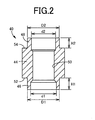
- FIG 2 is a sectional view of an initial shape of the bearing member 40 before the bearing member 40 is disposed in the pedal arm 14.
- the bearing member 40 has a cylindrical large-diameter tubular portion 44 having an external diameter larger than the diameter of each of the mounting holes 32h, 34h and located between the pair of halves 32, 34, and a pair of a first connecting portion 46 and a second connecting portion 48 having a cylindrical shape and projecting coaxially from both end faces 52, 54 of the large-diameter tubular portion 44, respectively, in an axial direction.
- the bearing member 40 is fixed, at the first connecting portion 46 and the second connecting portion 48, to the mounting holes 32h, 34h.
- the large-diameter tubular portion 44 has a cylindrical support inner peripheral face 50 that is slightly larger in diameter than a cylindrical outer peripheral face of the clevis pin 20, and the clevis pin 20 is brought into sliding contact with the support inner peripheral face 50 and disposed so as to be rotatable relative to the support inner peripheral face 50.
- An external diameter D1 of the first connecting portion 46 is smaller than the external diameter of the large-diameter tubular portion 44 and smaller than the diameter of the mounting hole 32h, and an inner diameter d1 thereof is larger than the diameter of the support inner peripheral face 50 of the large-diameter tubular portion 44.
- the first connecting portion 46 is passed through the mounting hole 32h of the half 32 and is compressed in the axial direction to be swaged (squeezed) as illustrated in FIG 1(b) .
- the first connecting portion 46 is fixedly fitted to the mounting hole 32h so that the peripheral portion of the mounting hole 32h is held between a swaged portion 47, which is formed from the first connecting portion 46, and the end face 52 of the large-diameter tubular portion 44.
- a projecting length H1 of the first connecting portion 46 is set to such a value that the first connecting portion 46 is fixedly fitted, by swaging, to the mounting hole 32h so that the peripheral portion of the mounting hole 32h is held between the swaged portion 47 and the end face 52 of the large-diameter tubular portion 44.
- the inner diameter d1 is set so as not to be smaller than the diameter of the support inner peripheral face 50 of the large-diameter tubular portion 44 even if the inner diameter d1 of the first connecting portion 46 is changed due to swaging.
- An external diameter D2 of the second connecting portion 48 is smaller than the external diameter of the large-diameter tubular portion 44 and smaller than the diameter of the mounting hole 34h, and an inner diameter d2 thereof is larger than the diameter of the support inner peripheral face 50 of the large-diameter tubular portion 44.
- the external diameter D2 is equal to the external diameter D1
- the inner diameter d2 is smaller than the inner diameter d1
- the second connecting portion 48 is larger in thickness than the first connecting portion 46 accordingly.
- the second connecting portion 48 When the second connecting portion 48 is passed through the mounting hole 34h of the half 34 and is compressed in the axial direction, the second connecting portion 48 is bulged and deformed radially outward as illustrated in FIG 1(c) , and a portion of the second connecting portion 48, which is apart from the end face 54 of the large-diameter tubular portion 44 by a predetermined distance g, is brought into close contact with an inner peripheral wall of the mounting hole 34h to be fixedly fitted to the mounting hole 34h.
- An axial length of the large-diameter tubular portion 44 is set to be shorter than an allowable lower limit of the distance L so that the large-diameter tubular portion 44 is interposed between the mounting holes 32h, 34h regardless of variations in the distance L between the mounting holes 32h, 34h of the pair of halves 32, 34.
- a projecting length H2 of the second connecting portion 48 is set based on variations in the distance L (more specifically, an allowable upper limit) such that, regardless of variations in the distance L, the second connecting portion 48 is passed through the mounting hole 34h and is bulged and deformed radially outward by being compressed in the axial direction to be brought into close contact with the inner peripheral wall of the mounting hole 34h.
- the predetermined distance g changes depending on variations in the distance L.
- the axial length of the large-diameter tubular portion 44 is set such that g > 0 is always satisfied regardless of variations in the distance L
- the projecting length H2 of the second connecting portion 48 is set such that the second connecting portion 48 is brought into close contact with the inner peripheral wall of the mounting hole 34h when the second connecting portion 48 is bulged and deformed radially outward by being compressed in the axial direction.
- the inner diameter d2 is set so as not to be smaller than the diameter of the support inner peripheral face 50 of the large-diameter tubular portion 44 even if the inner diameter d2 is changed due to the axial compressive deformation (bulging deformation) of the second connecting portion 48.
- the pedal arm 14 having such a configuration is manufactured as follows. Peripheral portions of the halves 32, 34 are integrally welded by arc welding or the like with the bearing member 40 disposed between the pair of halves 32, 34 as illustrated in FIG 3 . After that, the bearing member 40 is compressed as illustrated in FIG 4 , so that the bearing member 40 is fixedly fitted to the pair of halves 32, 34 of the pedal arm 14.
- FIG 3 illustrates a welding step
- FIG 4 illustrates a compression step.
- FIG 3(a) the pair of halves 32, 34 is placed in such a position that the opening sides of their hat-shapes face each other, the bearing member 40 is placed between the halves 32, 34, and the mounting holes 32h, 34h and the bearing member 40 are aligned with each other so as to be substantially coaxial with each other.
- FIG 3(b) the halves 32, 34 are brought closer to each other, the first connecting portion 46 and the second connecting portion 48 of the bearing member 40 are passed through the mounting holes 32h, 34h of the halves 32, 34, respectively, and the halves 32, 34 are overlapped with each other so that outer peripheral flanges 32f, 34f are brought into close contact with each other.
- the pair of halves 32, 34 is brought closer to each other so that the first connecting portion 46 and the second connecting portion 48 of the bearing member 40 are passed through the mounting holes 32h, 34h, respectively.
- a method of assembling them together may be set as needed.
- the first connecting portion 46 may be inserted into the mounting hole 32h of the half 32, which is one of the pair of halves 32, 34
- the second connecting portion 48 may be inserted into the mounting hole 34h of the half 34, which is the other one of the pair of halves 32, 34.
- outer edges of the outer peripheral flanges 32f, 34f are joined integrally with each other by arc welding or the like as illustrated in FIG 3(c) .
- the pedal arm 14 having a hollow structure in which the bearing member 40 is disposed across the mounting holes 32h, 34h is obtained.
- the distance L between the mounting holes 32h, 34h of the pair of halves 32, 34 varies depending on processing errors or the like of the halves 32, 34.
- the bearing member 40 is retained in the pedal arm 14 with a predetermined clearance corresponding to the distance g left between the large-diameter tubular portion 44 and each of the halves 32, 34 in the axial direction of the bearing member 40.
- the pedal arm 14 is supported by a supporting device (not illustrated) in a floating state where the pedal arm 14 is movable up and down, so that the bearing member 40 is located at an intermediate position between a punch 60, which is driven up and down, and a stationary holding jig 62.
- a ring-shaped projection 66 On a holding face 64 at an upper end of the holding jig 62, there is formed a ring-shaped projection 66 that has a diameter larger than the external diameter of the first connecting portion 46 and that defines a swaged shape of the first connecting portion 46.
- a projecting length h of the ring-shaped projection 66 is set such that a swaged amount, with which the peripheral portion of the mounting hole 32h is reliably held by swaging, is reliably obtained by the time when the distal end of the ring-shaped projection 66 contacts a lower face (outer face) of the half 32.
- FIG 4(b) illustrates a state where the punch 60 is moved downward and a pressing face 68 contacts the distal end of the second connecting portion 48 of the bearing member 40. After that, the pedal arm 14 is also moved downward as the punch 60 is moved downward.
- a guide pin 70 which is inserted into a space on the inner side of the support inner peripheral face 50 of the large-diameter tubular portion 44, is provided so as to project from the pressing face 68.
- FIG 4(c) illustrates a state where the distal end of the first connecting portion 46 of the bearing member 40 contacts the holding face 64 of the holding jig 62.
- FIG 4(d) illustrates a state where the first connecting portion 46, which is relatively thin, is swaged first by the compressive load to be fixedly fitted to the mounting hole 32h so that the peripheral portion of the mounting hole 32h is held between the end face 52 of the large-diameter tubular portion 44 and the swaged portion 47, which is formed from the first connecting portion 46, and the lower face (outer face) of the half 32 contacts the distal end of the ring-shaped projection 66 of the holding jig 62.
- the lower face of the half 32 contacts the distal end of the ring-shaped projection 66 of the holding jig 62 as described above, further compressive deformation (swaging) of the first connecting portion 46 is prevented.
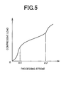
- FIG 5 illustrates an example of a variation characteristic of the compressive load with respect to a processing stroke (downward stroke of the punch 60) after the distal end of the first connecting portion 46 of the bearing member 40 contacts the holding face 64 of the holding jig 62 as illustrated in FIG 4(c) .
- a processing stroke st1 is a stroke at which the first connecting portion 46 buckles radially outward and swaging is started
- a processing stroke st2 is a stroke at which the lower face of the half 32 contacts the distal end of the ring-shaped projection 66 of the holding jig 62 as illustrated in FIG 4(d) .
- FIG 4(e) illustrates a state where, by bulging and deforming the second connecting portion 48 radially outward as described above, the portion of the second connecting portion 48, which is apart from the end face 54 of the large-diameter tubular portion 44 by the distance g, is brought into close contact with the inner peripheral wall of the mounting hole 34h, so that the second connecting portion 48 is fixedly fitted to the mounting hole 34h.
- the bearing member 40 of the brake pedal 10 is disposed so as to connect the pair of halves 32, 34 constituting the right and left side walls of the pedal arm 14, it is possible to easily and appropriately connect the clevis pin 20 to the pedal arm 14 by passing the clevis pin 20 through the bearing member 40. As a result, the efficiency of load transmission between the pedal arm 14 and the clevis pin 20 is secured sufficiently.
- the first connecting portion 46 that is connected to the mounting hole 32h is swaged by being compressed in the axial direction
- the first connecting portion 46 is fixedly fitted to the mounting hole 32h so that the peripheral portion of the mounting hole 32h is held between the swaged portion 47, which is formed from the first connecting portion 46, and the end face 52 of the large-diameter tubular portion 44.
- the second connecting portion 48 that is connected to the mounting hole 34h is bulged and deformed radially outward by being compressed in the axial direction, so that the portion of the second connecting portion 48, which is apart from the end face 54 of the large-diameter tubular portion 44 by the predetermined distance g, is brought into close contact with the inner peripheral wall of the mounting hole 34h.
- the second connecting portion 48 is fixedly fitted to the mounting hole 34h. Accordingly, even if the distance L between the pair of halves 32, 34 varies, variation is absorbed by changing a fixed portion at which the second connecting portion 48 is fixed to the mounting hole 34h. Therefore, it possible to fix the bearing member 40 without deforming the pedal arm 14. As a result, the bearing member 40 is disposed in the pedal arm 14 without reducing the pedal performances such as dimensional accuracy and strength of various portions of the pedal arm 14.
- the second connecting portion 48 is thicker than the first connecting portion 46, and in view of this, if a compressive load that is applied in the axial direction is increased gradually, the thin first connecting portion 46 is swaged first and then the second connecting portion 48 is bulged and deformed. Thus, it is possible to compress and deform the first connecting portion 46 and the second connecting portion 48 sequentially by a series of compression operations to fix them.
- the axial length of the large-diameter tubular portion 44 is set to be shorter than the allowable lower limit of the distance L so that, regardless of variations in the distance L, the large-diameter tubular portion 44 is interposed between the pair of halves 32, 34 with a clearance corresponding to the distance g.
- the projecting length H2 of the second connecting portion 48 is set such that, regardless of variations in the distance L, the second connecting portion 48 is passed through the mounting hole 34h and is then bulged and deformed radially outward by being compressed in the axial direction to be brought into close contact with the inner peripheral wall of the mounting hole 34h. This makes it possible to reliably fix the bearing member 40 across the pair of halves 32, 34 without deforming the pedal arm 14 regardless of variations in the distance L.
- the peripheral portions of the pair of halves 32, 34 are integrally welded in a state where the bearing member 40 is disposed between the pair of halves 32, 34 such that the first connecting portion 46 is passed through the mounting hole 32h and the second connecting portion 48 is passed through the mounting hole 34h, and subsequently, the bearing member 40 is compressed in the axial direction to increase the compressive load, the first connecting portion 46 is swaged to be fixed to the mounting hole 32h and the second connecting portion 48 is bulged and deformed radially outward to be fixed to the mounting hole 34h.
- the manufacturing cost is further reduced.
- pedal arm 20 clevis pin (connecting shaft) 32, 34 : half (plate member) 32h : mounting hole (first mounting hole) 34h : mounting hole (second mounting hole) 40 : bearing member 44 : large-diameter tubular portion 46 : first connecting portion 47 : swaged portion 48 : second connecting portion L : distance g : predetermined distance H2 : projecting length of the second connecting portion
Landscapes
- Engineering & Computer Science (AREA)
- General Engineering & Computer Science (AREA)
- Physics & Mathematics (AREA)
- General Physics & Mathematics (AREA)
- Automation & Control Theory (AREA)
- Mechanical Engineering (AREA)
- Manufacturing & Machinery (AREA)
- Mechanical Control Devices (AREA)
- Braking Elements And Transmission Devices (AREA)
- Arrangement And Mounting Of Devices That Control Transmission Of Motive Force (AREA)
Abstract


Description
- The invention relates to a pedal arm, and more specifically to an improvement of a tubular bearing member which is disposed across a pair of plate members that constitute side walls of the pedal arm and through which a connecting shaft is passed so as to be rotatable relative to the bearing member.
- When a shaft such as a clevis pin is connected to a pedal arm so as to be rotatable relative to the pedal arm or when a pedal arm is supported pivotably, a bearing member is disposed in a plate member that constitutes the pedal arm. One example of such a pedal arm is described in Patent Document 1. The pedal arm has a hollow structure formed of a pair of halves, the pair of halves respectively has connecting holes, and a clevis pin is passed through the connecting holes so as to be rotatable relative to the halves. A cylindrical bearing member is fixedly provided in the connecting hole of one of the halves. Further, in an upper end portion of the pedal arm, at which the pedal arm is pivotably supported by a support shaft, burring holes are respectively formed in the pair of halves, and a cylindrical boss is disposed so as to pass through the burring holes and is fixed to the burring holes by welding.
-
Patent Document 2 describes a technique in which a bearing member is swaged to be fixed to a mounting hole formed in a plate member that constitutes a pedal arm, and a connecting shaft such as a support shaft is connected to the plate member via the bearing member so as to be rotatable relative to the plate member. The bearing member includes: (a) a large-diameter tubular portion which has an external diameter larger than the diameter of the mounting hole and through which the connecting shaft is passed so as to be rotatable relative to the large-diameter tubular portion, and (b) a connecting portion that has an external diameter smaller than the diameter of the mounting hole, that is formed coaxially with the large-diameter tubular portion so as to project from one end face of the large-diameter tubular portion, and that is passed through the mounting hole, wherein (c) when the connecting portion is compressed in the axial direction to be swaged (compressed), a peripheral portion of the mounting hole is held between a swaged portion, which is formed from the connecting portion, and the end face of the large-diameter tubular portion, whereby the bearing member is fixedly fitted to the mounting hole. -
- Patent Document 1: Japanese Patent Application Publication No.
2007-122610 - Patent Document 2: Japanese Patent Application Publication No.
11-29014 - However, with regard to the bearing member for the clevis pin described in Patent Document 1, it is necessary to dispose the clevis pin across the connecting holes formed in the pair of halves, which may cause a problem regarding insertability of the clevis pin due to dimension errors or the like or may cause a possibility that the efficiency of load transmission between the clevis pin and the pedal arm will be reduced due to, for example, an inappropriate positional relationship between the clevis pin and the connecting holes. With regard to the bearing member (boss) to which the support shaft is connected, although there is no problem regarding insertability of the support shaft, it is necessary to fix the bearing member to the pair of halves by welding, which makes a work cumbersome and increases the cost. On the other hand, the technique described in
Patent Document 2 may be applied to a pedal arm having a hollow structure formed by fitting a pair of plate members together, so that connecting portions are formed at respective ends of the large-diameter tubular portion and swaged to be respectively fixed to the pair of plate members. However, if the distance between the pair of plate members varies, the pedal arm may be deformed by swaging. - The invention is made in light of the above-described circumstances, and it is an object of the invention to provide a fixation technique which is implemented easily and at low cost, and with which a bearing member is appropriately fixed regardless of variations in the distance between a pair of plate members of a pedal arm when the bearing member is disposed across the pair of plate members such that insertability of a connecting shaft is secured.
- The object indicated above is achieved in the first aspect of the invention, a bearing member for a pedal arm, which is a tubular bearing member which is disposed so as to connect a first mounting hole and a second mounting hole formed respectively in a pair of plate members constituting right and left side walls of the pedal arm and through which a connecting shaft is passed so as to be rotatable relative to the bearing member, the bearing member characterized by including: (a) a large-diameter tubular portion having an external diameter larger than a diameter of the first mounting hole and located between the pair of plate members; (b) a first connecting portion that has an external diameter smaller than the diameter of the first mounting hole, that is formed so as to project from one end face of the large-diameter tubular portion coaxially with the large-diameter tubular portion, that is passed through the first mounting hole, and that is fixedly fitted to the first mounting hole by being compressed in an axial direction to be swaged so that a peripheral portion of the first mounting hole is held between a swaged portion, which is formed from the first connecting portion, and the one end face of the large-diameter tubular portion; and (c) a second connecting portion that has an external diameter smaller than a diameter of the second mounting hole and a thickness larger than a thickness of the first connecting portion, that is formed so as to project from the other end face of the large-diameter tubular portion coaxially with the large-diameter tubular portion, that is passed through the second mounting hole, and that is fixedly fitted to the second mounting hole by being compressed in the axial direction to be bulged and deformed radially outward so that a portion of the second connecting portion, which is apart from the other end face of the large-diameter tubular portion by a predetermined distance, is brought into close contact with an inner peripheral wall of the second mounting hole.
- The second aspect of the invention, according to the bearing member for a pedal arm of the first aspect of the invention, characterized in that: (a) an axial length of the large-diameter tubular portion is set to be shorter than an allowable lower limit of a distance L between the pair of plate members so that the large-diameter tubular portion is interposed between the pair of plate members regardless of variation in the distance L; and (b) a projecting length of the second connecting portion from the other end face of the large-diameter tubular portion is set such that, regardless of variation in the distance L, the second connecting portion is passed through the second mounting hole and is bulged and deformed radially outward by being compressed in the axial direction so as to be brought into close contact with the inner peripheral wall of the second mounting hole.
- The third aspect of the invention of a pedal arm having a hollow structure formed by integrally welding peripheral portions of a pair of plate-like halves having shapes obtained by dividing a shape of the pedal arm in a width direction, characterized in that: one of the pair of halves and the other one of the pair of halves have a first mounting hole and a second mounting hole, respectively; and the bearing member according to the first or second aspect of the invention is disposed so as to connect the first mounting hole to the second mounting hole.
- The fourth aspect of the invention is a method for manufacturing the pedal arm according to the third aspect of the invention, the method characterized by including: a welding step of integrally welding the peripheral portions of the pair of halves in a state where the bearing member is disposed so as to locate the large-diameter tubular portion between the pair of halves, so that the first connecting portion is passed through the first mounting hole and the second connecting portion is passed through the second mounting hole; and a compression step of fixedly fitting the first connecting portion to the first mounting hole by swaging the first connecting portion, and fixedly fitting the second connecting portion to the second mounting hole by bulging and deforming the second connecting portion radially outward, in a series of compression processes in which the bearing member is compressed in the axial direction after the pair of halves are welded, and a compression load is increased.
- The bearing member of the pedal arm according to the first aspect of the invention is disposed so as to connect the pair of plate members constituting the right and left side walls of the pedal arm, it is possible to easily and appropriately connect the connecting shaft to the pedal arm by passing the connecting shaft through the bearing member . As a result, the efficiency of load transmission between the pedal arm and the connecting shaft is secured sufficiently. Further, when the first connecting portion that is connected to the first mounting hole is swaged by being compressed in the axial direction, the first connecting portion is fixedly fitted to the first mounting hole so that the peripheral portion of the first mounting hole is held between the swaged portion, which is formed from the first connecting portion, and the end face of the large-diameter tubular portion. Meanwhile, the second connecting portion that is connected to the second mounting hole is bulged and deformed radially outward by being compressed in the axial direction, so that the portion of the second connecting portion, which is apart from the end face of the large-diameter tubular portion by the predetermined distance, is brought into close contact with the inner peripheral wall of the second mounting hole. As a result, the second connecting portion is fixedly fitted to the second mounting hole. Accordingly, even if the distance L between the pair of plate members varies, variation is absorbed by changing a fixed portion at which the second connecting portion is fixed to the second mounting hole. Therefore, it is possible to fix the bearing member without deforming the pedal arm.
- Further, because it is only necessary to compress the bearing member in the axial direction to compress and deform (swage and bulge) the first connecting portion and the second connecting portion at both ends of the bearing member, it is possible to perform fixation more easily and more inexpensively than in a case where fixation is performed by welding, thereby reducing the manufacturing cost. Particularly, the second connecting portion is thicker than the first connecting portion, and in view of this, if a compressive load that is applied in the axial direction is increased gradually, the thin first connecting portion is swaged first and then the second connecting portion is bulged and deformed. Thus, it is possible to compress and deform the first connecting portion and the second connecting portion sequentially by a series of compression operations to fix them.
- In the second aspect of the invention, the axial length of the large-diameter tubular portion is set to be shorter than the allowable lower limit of the distance L so that, regardless of variations in the distance L, the large-diameter tubular portion is interposed between the pair of plate members. Moreover, the projecting length of the second connecting portion is set such that, regardless of variations in the distance L, the second connecting portion is passed through the second mounting hole and is then bulged and deformed radially outward by being compressed in the axial direction to be brought into close contact with the inner peripheral wall of the second mounting hole. This makes it possible to reliably fix the bearing member across the pair of plate members without deforming the pair of plate members regardless of variations in the distance L.
- In the third aspect of the invention, a pedal arm having a hollow structure formed by integrally welding peripheral portions of a pair of plate-like halves having shapes obtained by dividing a shape of the pedal arm in a width direction, characterized in that: one of the pair of halves and the other one of the pair of halves have a first mounting hole and a second mounting hole, respectively; and the bearing member according to claim 1 or 2 is disposed so as to connect the first mounting hole to the second mounting hole. Thus, it can be obtained that the substantially same actions and effects as the first or second aspect of the invention.
- The fourth aspect of the invention is a method for manufacturing the pedal arm according to the third aspect of the invention, in a series of processes in which the peripheral portions of the pair of halves are integrally welded in a state where the bearing member is disposed such that the first connecting portion is passed through the first mounting hole and the second connecting portion is passed through the second mounting hole, and subsequently, the bearing member is compressed in the axial direction to increase the compressive load, the first connecting portion is swaged to be fixed to the first mounting hole and the second connecting portion is bulged and deformed radially outward to be fixed to the second mounting hole. Thus, in addition to the same actions and effects as the third aspect of the invention can be obtained, the manufacturing cost is further reduced.
-
-
FIG 1 illustrates views showing a brake pedal for a service brake of a vehicle to which the invention is applied, whereinFIG 1(a) is a left side view,FIG 1(b) is an enlarged view of a section taken along the line IB-IB inFIG 1(a), and FIG 1(c) is an enlarged sectional view showing a portion IC inFIG 1(b) . -
FIG 2 is a sectional view of an initial shape of the bearing member before the bearing member of the embodiment ofFIG 1 is disposed in the pedal arm. -
FIG 3 illustrates a welding step in which peripheral portions of the halves are integrally welded by arc welding or the like with the bearing member disposed between the pair of halves. -
FIG 4 illustrates a compression step in which the bearing member is compressed, so that the bearing member is fixedly fitted to the pedal arm. -
FIG 5 illustrates a variation characteristic of the compressive load with respect to a processing stroke when the bearing member is compressed in the compression step ofFIG. 4 . - The invention is suitably applied to, for example, a brake pedal, a clutch pedal, an accelerator pedal, and the like for vehicles, but may also be applied to operation pedals other than pedals for vehicles. Further, the third and fourth inventions relate to the pedal arm having a hollow structure formed of a pair of halves (plate members). However, the hollow structure is not necessarily configured such that a whole circumference is sealed in a saclike form, but may be opened partially.
- The invention is suitably applied to a bearing member provided at a joint between a support shaft by which a pedal arm is pivotably supported and the pedal arm, a bearing member provided at a joint between a clevis pin that connects a pedal arm and a clevis such that the pedal arm and the clevis are rotatable relative to each other and the pedal arm, and the like.
- The external diameter of a large-diameter tubular portion of a bearing member should be larger than the diameter of a first mounting hole and the diameter of a first connecting portion, and the inner diameter of a second mounting hole and the external diameter of a second connecting portion may be either larger or smaller than the external diameter of the large-diameter tubular portion. The bearing member has a cylindrical support inner peripheral face along which a connecting shaft is extended so as to be rotatable relative to the support inner peripheral face. However, it is preferable that the support inner peripheral face be formed at the large-diameter tubular portion, and it is also preferable that inner diameters of the first connecting portion and the second connecting portion be set to be slightly larger than the diameter of the support inner peripheral face in consideration of a change in the inner diameter due to compressive deformation. That is, when the bearing member is compressed in an axial direction and receives a compressive load, compressive stress in a circumferential direction acts on inner peripheral side, so that the first connecting portion and second connecting portion are compressed and deformed so as to bulge mainly radially outward. As a result, a distal end portion of the first connecting portion is swaged radially outward so that a peripheral portion of the first mounting hole is held between the first connection portion and the end face of the large-diameter tubular portion, while the second connecting portion is bulged and deformed radially outward so as to be brought into close contact with an inner peripheral wall of the second mounting hole. However, the first and second connecting portions may also bulge radially inward to some extent due to deformation resistance or the like, and in view of this, the inner diameters of the first and second connecting portions are set so as not to be smaller than the diameter of the support inner peripheral face even if the first and second connecting portions bulge radially inward. The support inner peripheral face is a portion which is brought into sliding contact with an outer peripheral face of the connecting shaft, and the diameter of the support inner peripheral face is set to be slightly larger than the external diameter of the connecting shaft.
- The shape of the outer peripheral face of the large-diameter tubular portion is preferably cylindrical, but may be a polygonal column shape such as a square pole shape. The shapes of the inner and outer peripheral faces of the first connecting portion and the second connecting portion and the first mounting hole and the second mounting hole are also preferably cylindrical and a circular-hole shape, but a polygonal column shape or a polygonal hole may be employed, respectively. Further, the pair of plate members which constitute right and left side walls of the pedal arm according to the first invention may be a pair of halves having shapes obtained by dividing the shape of the pedal arm in a width direction, as in the case of the pedal arm according to the third invention, or may be, for example, a pair of flat side plate members fixedly fitted together by a plurality of connecting pins or the like in a such a position that the side plate members are substantially parallel to each other across a predetermined distance. As described above, it is possible to employ various forms.
- In the second invention, the axial length of the large-diameter tubular portion and the projecting length of the second connecting portion are set, for example, on the basis of an allowable lower limit and an allowable upper limit of a distance L between the pair of plate members. However, when the first invention is implemented, the axial length may be set with a sufficient margin so that the large-diameter tubular portion is interposed between the pair of plate members regardless of variations in the distance L, and the projecting length may be set with a sufficient margin so that the second connecting portion is bulged and deformed by being compressed in the axial direction so that the second connecting portion is brought into close contact with the inner peripheral wall of the second mounting hole.
- In the fourth invention, peripheral portions of the pair of halves are welded integrally in a state where the bearing member is disposed such that the first connecting portion is passed through the first mounting hole and the second connecting portion is passed through the second mounting hole, and after that, the bearing member is compressed in the axial direction so that the first connecting portion is swaged to be fixedly fitted to the first mounting hole while the second connecting portion is bulged and deformed radially outward to be fixedly fitted to the second mounting hole. However, when the other inventions are implemented, for example, swaging of the first connecting portion and bulging deformation of the second connecting portion may be performed in different steps. For example, the bearing member is axially compressed with the first connecting portion passed through the first mounting hole, so that the first connecting portion is swaged to be fixedly fitted to the first mounting hole. Subsequently, the peripheral portions of the pair of halves are integrally welded with the second connecting portion passed through the second mounting hole, and then, the bearing member is compressed again in the axial direction, so that the second connecting portion is bulged and deformed radially outward to be fixedly fitted to the second mounting hole.
- Hereinafter, embodiments of the invention will be described in detail with reference to the accompanying drawings.
-
FIG 1 illustrates views showing abrake pedal 10 for a service brake of a vehicle to which the invention is applied, whereinFIG 1(a) is a left side view,FIG 1(b) is an enlarged view of a section taken along the line IB-IB inFIG 1(a), and FIG 1(c) is an enlarged sectional view showing a portion IC inFIG. 1(b) . Thebrake pedal 10 has apedal arm 14 as a main component. Thebrake pedal 10 is supported, at an upper end portion of thepedal arm 14, so as to be pivotable about a support axis O, which is an axis of a substantiallyhorizontal support shaft 12. A lower end portion of thepedal arm 14 is bent diagonally upward in a direction toward the rear of the vehicle so as to be oriented toward a driver seat, and apedal sheet 18 is fixedly fitted to the lower end portion of thepedal arm 14. When a driver depresses thepedal sheet 18, thebrake pedal 10 pivots clockwise about thesupport shaft 12 inFIG 1(a) . Anoutput member 22 such as a pushrod is connected to thebrake pedal 10 via aclevis 24 so as to be pivotable, relative to thebrake pedal 10, about an axis of aclevis pin 20, which is substantially parallel to thesupport shaft 12. When theoutput member 22 is mechanically pushed leftward inFIG 1(a) as thebrake pedal 10 pivots, brake hydraulic pressure is generated on the basis of the depression force applied to thebrake pedal 10. In the present embodiment, theclevis pin 20 corresponds to a connecting shaft. - The
pedal arm 14 has a hollow structure having a substantially quadrangular section, and is formed of a pair ofhalves halves halves peripheral flanges peripheral flanges FIG 1(b) indicates welded portions of the outerperipheral flanges - In pivot connecting portions of the pair of
halves clevis pin 20 is disposed, there are concentrically formed circular mountingholes clevis pin 20, and ametal bearing member 40 is disposed across the mountingholes support shaft 12 and is fixedly fitted to the mountingholes member 40 has a cylindrical shape with steps. The shaft portion of theclevis pin 20, which has a cylindrical outer peripheral face, is passed through the bearingmember 40 so as to be rotatable relative to the bearingmember 40, and theclevis pin 20 is prevented from being slipped out of the bearingmember 40 by a snap ring or the like. The pair ofhalves pedal arm 14, and the mountingholes halves holes -
FIG 2 is a sectional view of an initial shape of the bearingmember 40 before the bearingmember 40 is disposed in thepedal arm 14. The bearingmember 40 has a cylindrical large-diameter tubular portion 44 having an external diameter larger than the diameter of each of the mountingholes halves portion 46 and a second connectingportion 48 having a cylindrical shape and projecting coaxially from both end faces 52, 54 of the large-diameter tubular portion 44, respectively, in an axial direction. The bearingmember 40 is fixed, at the first connectingportion 46 and the second connectingportion 48, to the mountingholes diameter tubular portion 44 has a cylindrical support innerperipheral face 50 that is slightly larger in diameter than a cylindrical outer peripheral face of theclevis pin 20, and theclevis pin 20 is brought into sliding contact with the support innerperipheral face 50 and disposed so as to be rotatable relative to the support innerperipheral face 50. - An external diameter D1 of the first connecting
portion 46 is smaller than the external diameter of the large-diameter tubular portion 44 and smaller than the diameter of the mountinghole 32h, and an inner diameter d1 thereof is larger than the diameter of the support innerperipheral face 50 of the large-diameter tubular portion 44. The first connectingportion 46 is passed through the mountinghole 32h of thehalf 32 and is compressed in the axial direction to be swaged (squeezed) as illustrated inFIG 1(b) . As a result, the first connectingportion 46 is fixedly fitted to the mountinghole 32h so that the peripheral portion of the mountinghole 32h is held between a swagedportion 47, which is formed from the first connectingportion 46, and theend face 52 of the large-diameter tubular portion 44. A projecting length H1 of the first connectingportion 46 is set to such a value that the first connectingportion 46 is fixedly fitted, by swaging, to the mountinghole 32h so that the peripheral portion of the mountinghole 32h is held between the swagedportion 47 and theend face 52 of the large-diameter tubular portion 44. Further, the inner diameter d1 is set so as not to be smaller than the diameter of the support innerperipheral face 50 of the large-diameter tubular portion 44 even if the inner diameter d1 of the first connectingportion 46 is changed due to swaging. - An external diameter D2 of the second connecting
portion 48 is smaller than the external diameter of the large-diameter tubular portion 44 and smaller than the diameter of the mountinghole 34h, and an inner diameter d2 thereof is larger than the diameter of the support innerperipheral face 50 of the large-diameter tubular portion 44. Although the external diameter D2 is equal to the external diameter D1, the inner diameter d2 is smaller than the inner diameter d1 and the second connectingportion 48 is larger in thickness than the first connectingportion 46 accordingly. When the second connectingportion 48 is passed through the mountinghole 34h of thehalf 34 and is compressed in the axial direction, the second connectingportion 48 is bulged and deformed radially outward as illustrated inFIG 1(c) , and a portion of the second connectingportion 48, which is apart from theend face 54 of the large-diameter tubular portion 44 by a predetermined distance g, is brought into close contact with an inner peripheral wall of the mountinghole 34h to be fixedly fitted to the mountinghole 34h. An axial length of the large-diameter tubular portion 44 is set to be shorter than an allowable lower limit of the distance L so that the large-diameter tubular portion 44 is interposed between the mountingholes holes halves portion 48 is set based on variations in the distance L (more specifically, an allowable upper limit) such that, regardless of variations in the distance L, the second connectingportion 48 is passed through the mountinghole 34h and is bulged and deformed radially outward by being compressed in the axial direction to be brought into close contact with the inner peripheral wall of the mountinghole 34h. That is, because the mountinghole 32h of thehalf 32 is fixed while being in close contact with theend face 52 of the large-diameter tubular portion 44, the predetermined distance g changes depending on variations in the distance L. However, the axial length of the large-diameter tubular portion 44 is set such that g > 0 is always satisfied regardless of variations in the distance L, and the projecting length H2 of the second connectingportion 48 is set such that the second connectingportion 48 is brought into close contact with the inner peripheral wall of the mountinghole 34h when the second connectingportion 48 is bulged and deformed radially outward by being compressed in the axial direction. The inner diameter d2 is set so as not to be smaller than the diameter of the support innerperipheral face 50 of the large-diameter tubular portion 44 even if the inner diameter d2 is changed due to the axial compressive deformation (bulging deformation) of the second connectingportion 48. - The
pedal arm 14 having such a configuration is manufactured as follows. Peripheral portions of thehalves member 40 disposed between the pair ofhalves FIG 3 . After that, the bearingmember 40 is compressed as illustrated inFIG 4 , so that the bearingmember 40 is fixedly fitted to the pair ofhalves pedal arm 14.FIG 3 illustrates a welding step andFIG 4 illustrates a compression step. - The welding step in
FIG 3 will be described below in detail. InFIG 3(a) , the pair ofhalves member 40 is placed between thehalves holes member 40 are aligned with each other so as to be substantially coaxial with each other. InFIG 3(b) , thehalves portion 46 and the second connectingportion 48 of the bearingmember 40 are passed through the mountingholes halves halves peripheral flanges halves portion 46 and the second connectingportion 48 of the bearingmember 40 are passed through the mountingholes portion 46 may be inserted into the mountinghole 32h of thehalf 32, which is one of the pair ofhalves portion 48 may be inserted into the mountinghole 34h of thehalf 34, which is the other one of the pair ofhalves peripheral flanges FIG 3(c) . Thus, thepedal arm 14 having a hollow structure in which the bearingmember 40 is disposed across the mountingholes holes halves halves diameter tubular portion 44 and the projecting length H2 of the second connectingportion 48, the bearingmember 40 is retained in thepedal arm 14 with a predetermined clearance corresponding to the distance g left between the large-diameter tubular portion 44 and each of thehalves member 40. - In the compression step in
FIG 4 , initially, as illustrated inFIG 4(a) , thepedal arm 14 is supported by a supporting device (not illustrated) in a floating state where thepedal arm 14 is movable up and down, so that the bearingmember 40 is located at an intermediate position between apunch 60, which is driven up and down, and astationary holding jig 62. On a holdingface 64 at an upper end of the holdingjig 62, there is formed a ring-shapedprojection 66 that has a diameter larger than the external diameter of the first connectingportion 46 and that defines a swaged shape of the first connectingportion 46. A projecting length h of the ring-shapedprojection 66 is set such that a swaged amount, with which the peripheral portion of the mountinghole 32h is reliably held by swaging, is reliably obtained by the time when the distal end of the ring-shapedprojection 66 contacts a lower face (outer face) of thehalf 32.FIG 4(b) illustrates a state where thepunch 60 is moved downward and apressing face 68 contacts the distal end of the second connectingportion 48 of the bearingmember 40. After that, thepedal arm 14 is also moved downward as thepunch 60 is moved downward. On thepressing face 68 of thepunch 60, aguide pin 70, which is inserted into a space on the inner side of the support innerperipheral face 50 of the large-diameter tubular portion 44, is provided so as to project from thepressing face 68. -
FIG 4(c) illustrates a state where the distal end of the first connectingportion 46 of the bearingmember 40 contacts the holdingface 64 of the holdingjig 62. When thepunch 60 is further moved downward from this state, the first connectingportion 46 and the second connectingportion 48 are compressed and deformed on the basis of a compressive load applied by thepunch 60.FIG 4(d) illustrates a state where the first connectingportion 46, which is relatively thin, is swaged first by the compressive load to be fixedly fitted to the mountinghole 32h so that the peripheral portion of the mountinghole 32h is held between theend face 52 of the large-diameter tubular portion 44 and the swagedportion 47, which is formed from the first connectingportion 46, and the lower face (outer face) of thehalf 32 contacts the distal end of the ring-shapedprojection 66 of the holdingjig 62. When the lower face of thehalf 32 contacts the distal end of the ring-shapedprojection 66 of the holdingjig 62 as described above, further compressive deformation (swaging) of the first connectingportion 46 is prevented.FIG 5 illustrates an example of a variation characteristic of the compressive load with respect to a processing stroke (downward stroke of the punch 60) after the distal end of the first connectingportion 46 of the bearingmember 40 contacts the holdingface 64 of the holdingjig 62 as illustrated inFIG 4(c) . A processing stroke st1 is a stroke at which the first connectingportion 46 buckles radially outward and swaging is started, and a processing stroke st2 is a stroke at which the lower face of thehalf 32 contacts the distal end of the ring-shapedprojection 66 of the holdingjig 62 as illustrated inFIG 4(d) . - When the
punch 60 is further moved downward from the state inFIG 4(d) , the compressive load further increases as illustrated inFIG 5 and the second connectingportion 48, which is relatively thick, is bulged and deformed radially outward.FIG 4(e) illustrates a state where, by bulging and deforming the second connectingportion 48 radially outward as described above, the portion of the second connectingportion 48, which is apart from theend face 54 of the large-diameter tubular portion 44 by the distance g, is brought into close contact with the inner peripheral wall of the mountinghole 34h, so that the second connectingportion 48 is fixedly fitted to the mountinghole 34h. Thus, a series of compression processing for fixing the bearingmember 40 to thepedal arm 14 is finished, thepunch 60 is lifted up to its original position, which is the same as that inFIG 4(a) , as illustrated inFIG 4(f) , and accordingly thepedal arm 14 is lifted to the intermediate position by the supporting device (not illustrated). - Because the bearing
member 40 of thebrake pedal 10 according to the present embodiment is disposed so as to connect the pair ofhalves pedal arm 14, it is possible to easily and appropriately connect theclevis pin 20 to thepedal arm 14 by passing theclevis pin 20 through the bearingmember 40. As a result, the efficiency of load transmission between thepedal arm 14 and theclevis pin 20 is secured sufficiently. - Further, when the first connecting
portion 46 that is connected to the mountinghole 32h is swaged by being compressed in the axial direction, the first connectingportion 46 is fixedly fitted to the mountinghole 32h so that the peripheral portion of the mountinghole 32h is held between the swagedportion 47, which is formed from the first connectingportion 46, and theend face 52 of the large-diameter tubular portion 44. Meanwhile, the second connectingportion 48 that is connected to the mountinghole 34h is bulged and deformed radially outward by being compressed in the axial direction, so that the portion of the second connectingportion 48, which is apart from theend face 54 of the large-diameter tubular portion 44 by the predetermined distance g, is brought into close contact with the inner peripheral wall of the mountinghole 34h. As a result, the second connectingportion 48 is fixedly fitted to the mountinghole 34h. Accordingly, even if the distance L between the pair ofhalves portion 48 is fixed to the mountinghole 34h. Therefore, it possible to fix the bearingmember 40 without deforming thepedal arm 14. As a result, the bearingmember 40 is disposed in thepedal arm 14 without reducing the pedal performances such as dimensional accuracy and strength of various portions of thepedal arm 14. - Further, because it is only necessary to compress the bearing
member 40 in the axial direction to compress and deform (swage and bulge) the first connectingportion 46 and the second connectingportion 48 at both ends of the bearingmember 40, it is possible to perform fixation more easily and more inexpensively than in a case where fixation is performed by welding, thereby reducing the manufacturing cost. Particularly, the second connectingportion 48 is thicker than the first connectingportion 46, and in view of this, if a compressive load that is applied in the axial direction is increased gradually, the thin first connectingportion 46 is swaged first and then the second connectingportion 48 is bulged and deformed. Thus, it is possible to compress and deform the first connectingportion 46 and the second connectingportion 48 sequentially by a series of compression operations to fix them. - Further, the axial length of the large-
diameter tubular portion 44 is set to be shorter than the allowable lower limit of the distance L so that, regardless of variations in the distance L, the large-diameter tubular portion 44 is interposed between the pair ofhalves portion 48 is set such that, regardless of variations in the distance L, the second connectingportion 48 is passed through the mountinghole 34h and is then bulged and deformed radially outward by being compressed in the axial direction to be brought into close contact with the inner peripheral wall of the mountinghole 34h. This makes it possible to reliably fix the bearingmember 40 across the pair ofhalves pedal arm 14 regardless of variations in the distance L. - Further, in the present embodiment, in a series of processes in which the peripheral portions of the pair of
halves member 40 is disposed between the pair ofhalves portion 46 is passed through the mountinghole 32h and the second connectingportion 48 is passed through the mountinghole 34h, and subsequently, the bearingmember 40 is compressed in the axial direction to increase the compressive load, the first connectingportion 46 is swaged to be fixed to the mountinghole 32h and the second connectingportion 48 is bulged and deformed radially outward to be fixed to the mountinghole 34h. Thus, the manufacturing cost is further reduced. - The embodiments of the invention are described in detail with reference to the drawings. However, the above-described embodiments are just examples of the embodiments. The invention may be implemented in various other embodiments obtained by making modifications or improvements to the above-described embodiments on the basis of the knowledge of persons skilled in the art.
- 14 : pedal arm 20 : clevis pin (connecting shaft) 32, 34 : half (plate member) 32h : mounting hole (first mounting hole) 34h : mounting hole (second mounting hole) 40 : bearing member 44 : large-diameter tubular portion 46 : first connecting portion 47 : swaged portion 48 : second connecting portion L : distance g : predetermined distance H2 : projecting length of the second connecting portion
Claims (4)
- A bearing member for a pedal arm, which is a tubular bearing member which is disposed so as to connect a first mounting hole and a second mounting hole formed respectively in a pair of plate members constituting right and left side walls of the pedal arm and through which a connecting shaft is passed so as to be rotatable relative to the bearing member, the bearing member characterized by comprising:a large-diameter tubular portion having an external diameter larger than a diameter of the first mounting hole and located between the pair of plate members;a first connecting portion that has an external diameter smaller than the diameter of the first mounting hole, that is formed so as to project from one end face of the large-diameter tubular portion coaxially with the large-diameter tubular portion, that is passed through the first mounting hole, and that is fixedly fitted to the first mounting hole by being compressed in an axial direction to be swaged so that a peripheral portion of the first mounting hole is held between a swaged portion, which is formed from the first connecting portion, and the one end face of the large-diameter tubular portion; anda second connecting portion that has an external diameter smaller than a diameter of the second mounting hole and a thickness larger than a thickness of the first connecting portion, that is formed so as to project from the other end face of the large-diameter tubular portion coaxially with the large-diameter tubular portion, that is passed through the second mounting hole, and that is fixedly fitted to the second mounting hole by being compressed in the axial direction to be bulged and deformed radially outward so that a portion of the second connecting portion, which is apart from the other end face of the large-diameter tubular portion by a predetermined distance, is brought into close contact with an inner peripheral wall of the second mounting hole.
- The bearing member for a pedal arm according to claim 1, characterized in that:an axial length of the large-diameter tubular portion is set to be shorter than an allowable lower limit of a distance L between the pair of plate members so that the large-diameter tubular portion is interposed between the pair of plate members regardless of variation in the distance L; anda projecting length of the second connecting portion from the other end face of the large-diameter tubular portion is set such that, regardless of variation in the distance L, the second connecting portion is passed through the second mounting hole and is bulged and deformed radially outward by being compressed in the axial direction so as to be brought into close contact with the inner peripheral wall of the second mounting hole.
- A pedal arm having a hollow structure formed by integrally welding peripheral portions of a pair of plate-like halves having shapes obtained by dividing a shape of the pedal arm in a width direction, characterized in that:one of the pair of halves and the other one of the pair of halves have a first mounting hole and a second mounting hole, respectively; andthe bearing member according to claim 1 or 2 is disposed so as to connect the first mounting hole to the second mounting hole.
- A method for manufacturing the pedal arm according to claim 3, the method characterized by comprising:a welding step of integrally welding the peripheral portions of the pair of halves in a state where the bearing member is disposed so as to locate the large-diameter tubular portion between the pair of halves, so that the first connecting portion is passed through the first mounting hole and the second connecting portion is passed through the second mounting hole; anda compression step of fixedly fitting the first connecting portion to the first mounting hole by swaging the first connecting portion, and fixedly fitting the second connecting portion to the second mounting hole by bulging and deforming the second connecting portion radially outward, in a series of compression processes in which the bearing member is compressed in the axial direction after the pair of halves are welded, and a compression load is increased.
Applications Claiming Priority (2)
| Application Number | Priority Date | Filing Date | Title |
|---|---|---|---|
| JP2011119542A JP4918620B1 (en) | 2011-05-27 | 2011-05-27 | Pedal arm bearing member, pedal arm, and pedal arm manufacturing method |
| PCT/JP2011/073266 WO2012164768A1 (en) | 2011-05-27 | 2011-10-07 | Pedal arm bearing member, pedal arm, and method for manufacturing pedal arm |
Publications (3)
| Publication Number | Publication Date |
|---|---|
| EP2717112A1 true EP2717112A1 (en) | 2014-04-09 |
| EP2717112A4 EP2717112A4 (en) | 2017-02-08 |
| EP2717112B1 EP2717112B1 (en) | 2018-12-12 |
Family
ID=46243789
Family Applications (1)
| Application Number | Title | Priority Date | Filing Date |
|---|---|---|---|
| EP11866926.6A Not-in-force EP2717112B1 (en) | 2011-05-27 | 2011-10-07 | Pedal arm bearing member, pedal arm, and method for manufacturing pedal arm |
Country Status (5)
| Country | Link |
|---|---|
| US (1) | US9958896B2 (en) |
| EP (1) | EP2717112B1 (en) |
| JP (1) | JP4918620B1 (en) |
| CN (1) | CN103562813B (en) |
| WO (1) | WO2012164768A1 (en) |
Families Citing this family (7)
| Publication number | Priority date | Publication date | Assignee | Title |
|---|---|---|---|---|
| JP6178707B2 (en) * | 2013-11-21 | 2017-08-09 | 豊田鉄工株式会社 | Vehicle operation pedal |
| US9645600B2 (en) * | 2014-08-22 | 2017-05-09 | Ksr Ip Holdings Llc. | Two piece pedal arm |
| JP7305578B2 (en) * | 2020-02-14 | 2023-07-10 | 豊田鉄工株式会社 | Vehicle pedal device |
| JP7505738B2 (en) * | 2020-03-27 | 2024-06-25 | ヒルタ工業株式会社 | Pedal arm |
| JP2022078512A (en) * | 2020-11-13 | 2022-05-25 | 豊田鉄工株式会社 | Hollow pedal member |
| CN112692513A (en) * | 2020-11-23 | 2021-04-23 | 协展(福建)机械工业有限公司 | Processing technology of hollow arm of automobile pedal rod |
| JP7477488B2 (en) * | 2021-11-10 | 2024-05-01 | 豊田鉄工株式会社 | Pedal device for vehicle |
Family Cites Families (14)
| Publication number | Priority date | Publication date | Assignee | Title |
|---|---|---|---|---|
| JPH0726031Y2 (en) * | 1989-11-15 | 1995-06-14 | 日本ドライブイット株式会社 | Caulking device |
| JP3420595B2 (en) * | 1992-06-09 | 2003-06-23 | 住友軽金属工業株式会社 | Automotive operation pedal and method of manufacturing the same |
| JP4050807B2 (en) | 1997-07-14 | 2008-02-20 | 大塚工機株式会社 | Brake pipe shaft mounting structure |
| DE10039808A1 (en) * | 2000-08-16 | 2002-02-28 | Volkswagen Ag | Plastic journal bearing bushing for support of a motor vehicle pedal on its axle, has a hollow construction allowing easy compressibility and so reducing machining tolerances in the associated parts |
| US8186920B2 (en) * | 2001-07-19 | 2012-05-29 | Whitesell International Corporation | Clinch element and method and apparatus for attaching a clinch element to a panel |
| FR2844763B1 (en) * | 2002-09-19 | 2004-11-12 | Renault Sa | DEVICE FOR MOUNTING A PEDAL FOR A MOTOR VEHICLE |
| US7409889B2 (en) * | 2003-08-27 | 2008-08-12 | Robert Bosch Gmbh | Booster control rod coupling arrangement |
| US7415909B2 (en) * | 2004-03-31 | 2008-08-26 | Mazda Motor Corporation | Support structure for pedal of vehicle |
| JP2007122610A (en) * | 2005-10-31 | 2007-05-17 | Futaba Industrial Co Ltd | Vehicular pedal device |
| DE102006033608B3 (en) * | 2006-07-18 | 2008-02-21 | Edscha Cabrio-Dachsysteme Gmbh | Bearing device has partial hollow element provided with two wall areas which has opening, where punching bush is supports separate component, which has punching blade, which is in clamping contact with punched opening of wall area |
| JP5258750B2 (en) * | 2007-03-29 | 2013-08-07 | 株式会社インフェック | Vehicle pedal |
| AU2008349207B2 (en) * | 2008-01-31 | 2013-03-28 | Toyoda Iron Works Co., Ltd. | Vehicle operation pedal device |
| JP4746681B2 (en) * | 2009-01-21 | 2011-08-10 | 豊田鉄工株式会社 | Operation pedal device for vehicle |
| JP5144856B2 (en) * | 2009-09-17 | 2013-02-13 | 豊田鉄工株式会社 | Operation pedal and lap welding method |
-
2011
- 2011-05-27 JP JP2011119542A patent/JP4918620B1/en not_active Expired - Fee Related
- 2011-10-07 US US14/122,113 patent/US9958896B2/en not_active Expired - Fee Related
- 2011-10-07 EP EP11866926.6A patent/EP2717112B1/en not_active Not-in-force
- 2011-10-07 WO PCT/JP2011/073266 patent/WO2012164768A1/en not_active Ceased
- 2011-10-07 CN CN201180071197.2A patent/CN103562813B/en not_active Expired - Fee Related
Non-Patent Citations (1)
| Title |
|---|
| See references of WO2012164768A1 * |
Also Published As
| Publication number | Publication date |
|---|---|
| EP2717112B1 (en) | 2018-12-12 |
| JP2012248019A (en) | 2012-12-13 |
| CN103562813B (en) | 2014-11-26 |
| US20140123801A1 (en) | 2014-05-08 |
| US9958896B2 (en) | 2018-05-01 |
| CN103562813A (en) | 2014-02-05 |
| WO2012164768A1 (en) | 2012-12-06 |
| EP2717112A4 (en) | 2017-02-08 |
| JP4918620B1 (en) | 2012-04-18 |
Similar Documents
| Publication | Publication Date | Title |
|---|---|---|
| EP2717112B1 (en) | Pedal arm bearing member, pedal arm, and method for manufacturing pedal arm | |
| US20150352622A1 (en) | Method for forming a pressed component, method for manufacturing a pressed component, and die apparatus for forming a pressed component | |
| US20080014044A1 (en) | Spacing rivet, riveted joint and method for their production | |
| EP3196082B1 (en) | Pedal device for vehicle | |
| US9550477B2 (en) | Vehicle pedal device | |
| JP6317330B2 (en) | Suspension arm and method for manufacturing suspension arm | |
| US10711822B2 (en) | Nut integrated with bracket and method of manufacturing the same | |
| US11072373B2 (en) | Vehicle structural member and method for producing same | |
| GB2455443A (en) | Pipe member and method of manufacturing the same | |
| EP2669758B1 (en) | Pedal arm bearing member and pedal arm | |
| EP2378385A1 (en) | Link connection structure of operation pedal device for vehicle | |
| CN101932985A (en) | Operating pedal device for vehicles | |
| JPWO2015174432A1 (en) | Yoke for cross shaft type universal joint and method for manufacturing the same | |
| JP2007155131A (en) | Joint device | |
| CN110719820B (en) | Stepped tubular member and method for manufacturing the stepped tubular member | |
| JP3953044B2 (en) | Carrier plate and manufacturing method thereof | |
| JP5168440B2 (en) | Driving part fastening method and driving part | |
| JP2010038195A (en) | Torque rod and manufacturing method therefor | |
| JP6630300B2 (en) | Processing method of cylindrical body and cylindrical body | |
| JP7334749B2 (en) | METHOD FOR JOINING METAL PARTS, METHOD FOR MANUFACTURING JOINTED PARTS, AND JOINT STRUCTURE FOR METAL PARTS | |
| KR101576401B1 (en) | Method for manufacturing multi-stage gear, and multi-stage gear | |
| JPH10220577A (en) | Shift fork shaft | |
| EP3093205A1 (en) | Operating pedal device for vehicle and method for manufacturing operating pedal device for vehicle | |
| JP2019028938A (en) | Operation pedal device for vehicle | |
| JP2016211355A (en) | Clamp metal fitting device manufacturing method and clamp metal fitting device |
Legal Events
| Date | Code | Title | Description |
|---|---|---|---|
| PUAI | Public reference made under article 153(3) epc to a published international application that has entered the european phase |
Free format text: ORIGINAL CODE: 0009012 |
|
| 17P | Request for examination filed |
Effective date: 20130930 |
|
| AK | Designated contracting states |
Kind code of ref document: A1 Designated state(s): AL AT BE BG CH CY CZ DE DK EE ES FI FR GB GR HR HU IE IS IT LI LT LU LV MC MK MT NL NO PL PT RO RS SE SI SK SM TR |
|
| DAX | Request for extension of the european patent (deleted) | ||
| RA4 | Supplementary search report drawn up and despatched (corrected) |
Effective date: 20170111 |
|
| RIC1 | Information provided on ipc code assigned before grant |
Ipc: F16C 33/08 20060101ALI20170104BHEP Ipc: G05G 1/44 20080401AFI20170104BHEP Ipc: G05G 1/46 20080401ALN20170104BHEP Ipc: G05G 1/50 20080401ALI20170104BHEP |
|
| REG | Reference to a national code |
Ref country code: DE Ref legal event code: R079 Ref document number: 602011054857 Country of ref document: DE Free format text: PREVIOUS MAIN CLASS: G05G0001460000 Ipc: G05G0001440000 |
|
| RIC1 | Information provided on ipc code assigned before grant |
Ipc: F16C 33/08 20060101ALI20171222BHEP Ipc: F16C 11/04 20060101ALI20171222BHEP Ipc: G05G 1/46 20080401ALN20171222BHEP Ipc: G05G 1/44 20080401AFI20171222BHEP Ipc: G05G 1/50 20080401ALI20171222BHEP |
|
| GRAP | Despatch of communication of intention to grant a patent |
Free format text: ORIGINAL CODE: EPIDOSNIGR1 |
|
| STAA | Information on the status of an ep patent application or granted ep patent |
Free format text: STATUS: GRANT OF PATENT IS INTENDED |
|
| RIC1 | Information provided on ipc code assigned before grant |
Ipc: F16C 11/04 20060101ALI20180125BHEP Ipc: G05G 1/50 20080401ALI20180125BHEP Ipc: G05G 1/46 20080401ALN20180125BHEP Ipc: F16C 33/08 20060101ALI20180125BHEP Ipc: G05G 1/44 20080401AFI20180125BHEP |
|
| INTG | Intention to grant announced |
Effective date: 20180207 |
|
| GRAS | Grant fee paid |
Free format text: ORIGINAL CODE: EPIDOSNIGR3 |
|
| GRAA | (expected) grant |
Free format text: ORIGINAL CODE: 0009210 |
|
| STAA | Information on the status of an ep patent application or granted ep patent |
Free format text: STATUS: THE PATENT HAS BEEN GRANTED |
|
| AK | Designated contracting states |
Kind code of ref document: B1 Designated state(s): AL AT BE BG CH CY CZ DE DK EE ES FI FR GB GR HR HU IE IS IT LI LT LU LV MC MK MT NL NO PL PT RO RS SE SI SK SM TR |
|
| REG | Reference to a national code |
Ref country code: GB Ref legal event code: FG4D |
|
| REG | Reference to a national code |
Ref country code: CH Ref legal event code: EP |
|
| REG | Reference to a national code |
Ref country code: AT Ref legal event code: REF Ref document number: 1076838 Country of ref document: AT Kind code of ref document: T Effective date: 20181215 |
|
| REG | Reference to a national code |
Ref country code: DE Ref legal event code: R096 Ref document number: 602011054857 Country of ref document: DE |
|
| REG | Reference to a national code |
Ref country code: IE Ref legal event code: FG4D |
|
| REG | Reference to a national code |
Ref country code: CH Ref legal event code: PK Free format text: BERICHTIGUNGEN |
|
| RIC2 | Information provided on ipc code assigned after grant |
Ipc: G05G 1/44 20080401AFI20180125BHEP Ipc: F16C 11/04 20060101ALI20180125BHEP Ipc: G05G 1/50 20080401ALI20180125BHEP Ipc: G05G 1/46 20080401ALN20180125BHEP Ipc: F16C 33/08 20060101ALI20180125BHEP |
|
| REG | Reference to a national code |
Ref country code: NL Ref legal event code: MP Effective date: 20181212 |
|
| REG | Reference to a national code |
Ref country code: LT Ref legal event code: MG4D |
|
| PG25 | Lapsed in a contracting state [announced via postgrant information from national office to epo] |
Ref country code: ES Free format text: LAPSE BECAUSE OF FAILURE TO SUBMIT A TRANSLATION OF THE DESCRIPTION OR TO PAY THE FEE WITHIN THE PRESCRIBED TIME-LIMIT Effective date: 20181212 Ref country code: LT Free format text: LAPSE BECAUSE OF FAILURE TO SUBMIT A TRANSLATION OF THE DESCRIPTION OR TO PAY THE FEE WITHIN THE PRESCRIBED TIME-LIMIT Effective date: 20181212 Ref country code: NO Free format text: LAPSE BECAUSE OF FAILURE TO SUBMIT A TRANSLATION OF THE DESCRIPTION OR TO PAY THE FEE WITHIN THE PRESCRIBED TIME-LIMIT Effective date: 20190312 Ref country code: BG Free format text: LAPSE BECAUSE OF FAILURE TO SUBMIT A TRANSLATION OF THE DESCRIPTION OR TO PAY THE FEE WITHIN THE PRESCRIBED TIME-LIMIT Effective date: 20190312 Ref country code: HR Free format text: LAPSE BECAUSE OF FAILURE TO SUBMIT A TRANSLATION OF THE DESCRIPTION OR TO PAY THE FEE WITHIN THE PRESCRIBED TIME-LIMIT Effective date: 20181212 Ref country code: LV Free format text: LAPSE BECAUSE OF FAILURE TO SUBMIT A TRANSLATION OF THE DESCRIPTION OR TO PAY THE FEE WITHIN THE PRESCRIBED TIME-LIMIT Effective date: 20181212 Ref country code: FI Free format text: LAPSE BECAUSE OF FAILURE TO SUBMIT A TRANSLATION OF THE DESCRIPTION OR TO PAY THE FEE WITHIN THE PRESCRIBED TIME-LIMIT Effective date: 20181212 |
|
| REG | Reference to a national code |
Ref country code: AT Ref legal event code: MK05 Ref document number: 1076838 Country of ref document: AT Kind code of ref document: T Effective date: 20181212 |
|
| PG25 | Lapsed in a contracting state [announced via postgrant information from national office to epo] |
Ref country code: SE Free format text: LAPSE BECAUSE OF FAILURE TO SUBMIT A TRANSLATION OF THE DESCRIPTION OR TO PAY THE FEE WITHIN THE PRESCRIBED TIME-LIMIT Effective date: 20181212 Ref country code: RS Free format text: LAPSE BECAUSE OF FAILURE TO SUBMIT A TRANSLATION OF THE DESCRIPTION OR TO PAY THE FEE WITHIN THE PRESCRIBED TIME-LIMIT Effective date: 20181212 Ref country code: AL Free format text: LAPSE BECAUSE OF FAILURE TO SUBMIT A TRANSLATION OF THE DESCRIPTION OR TO PAY THE FEE WITHIN THE PRESCRIBED TIME-LIMIT Effective date: 20181212 Ref country code: GR Free format text: LAPSE BECAUSE OF FAILURE TO SUBMIT A TRANSLATION OF THE DESCRIPTION OR TO PAY THE FEE WITHIN THE PRESCRIBED TIME-LIMIT Effective date: 20190313 |
|
| PG25 | Lapsed in a contracting state [announced via postgrant information from national office to epo] |
Ref country code: NL Free format text: LAPSE BECAUSE OF FAILURE TO SUBMIT A TRANSLATION OF THE DESCRIPTION OR TO PAY THE FEE WITHIN THE PRESCRIBED TIME-LIMIT Effective date: 20181212 |
|
| PG25 | Lapsed in a contracting state [announced via postgrant information from national office to epo] |
Ref country code: IT Free format text: LAPSE BECAUSE OF FAILURE TO SUBMIT A TRANSLATION OF THE DESCRIPTION OR TO PAY THE FEE WITHIN THE PRESCRIBED TIME-LIMIT Effective date: 20181212 Ref country code: PL Free format text: LAPSE BECAUSE OF FAILURE TO SUBMIT A TRANSLATION OF THE DESCRIPTION OR TO PAY THE FEE WITHIN THE PRESCRIBED TIME-LIMIT Effective date: 20181212 Ref country code: CZ Free format text: LAPSE BECAUSE OF FAILURE TO SUBMIT A TRANSLATION OF THE DESCRIPTION OR TO PAY THE FEE WITHIN THE PRESCRIBED TIME-LIMIT Effective date: 20181212 Ref country code: PT Free format text: LAPSE BECAUSE OF FAILURE TO SUBMIT A TRANSLATION OF THE DESCRIPTION OR TO PAY THE FEE WITHIN THE PRESCRIBED TIME-LIMIT Effective date: 20190412 |
|
| PG25 | Lapsed in a contracting state [announced via postgrant information from national office to epo] |
Ref country code: IS Free format text: LAPSE BECAUSE OF FAILURE TO SUBMIT A TRANSLATION OF THE DESCRIPTION OR TO PAY THE FEE WITHIN THE PRESCRIBED TIME-LIMIT Effective date: 20190412 Ref country code: SK Free format text: LAPSE BECAUSE OF FAILURE TO SUBMIT A TRANSLATION OF THE DESCRIPTION OR TO PAY THE FEE WITHIN THE PRESCRIBED TIME-LIMIT Effective date: 20181212 Ref country code: SM Free format text: LAPSE BECAUSE OF FAILURE TO SUBMIT A TRANSLATION OF THE DESCRIPTION OR TO PAY THE FEE WITHIN THE PRESCRIBED TIME-LIMIT Effective date: 20181212 Ref country code: EE Free format text: LAPSE BECAUSE OF FAILURE TO SUBMIT A TRANSLATION OF THE DESCRIPTION OR TO PAY THE FEE WITHIN THE PRESCRIBED TIME-LIMIT Effective date: 20181212 Ref country code: RO Free format text: LAPSE BECAUSE OF FAILURE TO SUBMIT A TRANSLATION OF THE DESCRIPTION OR TO PAY THE FEE WITHIN THE PRESCRIBED TIME-LIMIT Effective date: 20181212 |
|
| REG | Reference to a national code |
Ref country code: DE Ref legal event code: R097 Ref document number: 602011054857 Country of ref document: DE |
|
| PLBE | No opposition filed within time limit |
Free format text: ORIGINAL CODE: 0009261 |
|
| STAA | Information on the status of an ep patent application or granted ep patent |
Free format text: STATUS: NO OPPOSITION FILED WITHIN TIME LIMIT |
|
| PG25 | Lapsed in a contracting state [announced via postgrant information from national office to epo] |
Ref country code: SI Free format text: LAPSE BECAUSE OF FAILURE TO SUBMIT A TRANSLATION OF THE DESCRIPTION OR TO PAY THE FEE WITHIN THE PRESCRIBED TIME-LIMIT Effective date: 20181212 Ref country code: AT Free format text: LAPSE BECAUSE OF FAILURE TO SUBMIT A TRANSLATION OF THE DESCRIPTION OR TO PAY THE FEE WITHIN THE PRESCRIBED TIME-LIMIT Effective date: 20181212 Ref country code: DK Free format text: LAPSE BECAUSE OF FAILURE TO SUBMIT A TRANSLATION OF THE DESCRIPTION OR TO PAY THE FEE WITHIN THE PRESCRIBED TIME-LIMIT Effective date: 20181212 |
|
| 26N | No opposition filed |
Effective date: 20190913 |
|
| PGFP | Annual fee paid to national office [announced via postgrant information from national office to epo] |
Ref country code: DE Payment date: 20191028 Year of fee payment: 9 |
|
| PG25 | Lapsed in a contracting state [announced via postgrant information from national office to epo] |
Ref country code: TR Free format text: LAPSE BECAUSE OF FAILURE TO SUBMIT A TRANSLATION OF THE DESCRIPTION OR TO PAY THE FEE WITHIN THE PRESCRIBED TIME-LIMIT Effective date: 20181212 |
|
| PGFP | Annual fee paid to national office [announced via postgrant information from national office to epo] |
Ref country code: GB Payment date: 20191023 Year of fee payment: 9 |
|
| PG25 | Lapsed in a contracting state [announced via postgrant information from national office to epo] |
Ref country code: MC Free format text: LAPSE BECAUSE OF FAILURE TO SUBMIT A TRANSLATION OF THE DESCRIPTION OR TO PAY THE FEE WITHIN THE PRESCRIBED TIME-LIMIT Effective date: 20181212 |
|
| REG | Reference to a national code |
Ref country code: CH Ref legal event code: PL |
|
| PG25 | Lapsed in a contracting state [announced via postgrant information from national office to epo] |
Ref country code: CH Free format text: LAPSE BECAUSE OF NON-PAYMENT OF DUE FEES Effective date: 20191031 Ref country code: LI Free format text: LAPSE BECAUSE OF NON-PAYMENT OF DUE FEES Effective date: 20191031 Ref country code: LU Free format text: LAPSE BECAUSE OF NON-PAYMENT OF DUE FEES Effective date: 20191007 |
|
| REG | Reference to a national code |
Ref country code: BE Ref legal event code: MM Effective date: 20191031 |
|
| PG25 | Lapsed in a contracting state [announced via postgrant information from national office to epo] |
Ref country code: BE Free format text: LAPSE BECAUSE OF NON-PAYMENT OF DUE FEES Effective date: 20191031 |
|
| PG25 | Lapsed in a contracting state [announced via postgrant information from national office to epo] |
Ref country code: IE Free format text: LAPSE BECAUSE OF NON-PAYMENT OF DUE FEES Effective date: 20191007 |
|
| PGFP | Annual fee paid to national office [announced via postgrant information from national office to epo] |
Ref country code: FR Payment date: 20200914 Year of fee payment: 10 |
|
| REG | Reference to a national code |
Ref country code: DE Ref legal event code: R119 Ref document number: 602011054857 Country of ref document: DE |
|
| PG25 | Lapsed in a contracting state [announced via postgrant information from national office to epo] |
Ref country code: CY Free format text: LAPSE BECAUSE OF FAILURE TO SUBMIT A TRANSLATION OF THE DESCRIPTION OR TO PAY THE FEE WITHIN THE PRESCRIBED TIME-LIMIT Effective date: 20181212 |
|
| GBPC | Gb: european patent ceased through non-payment of renewal fee |
Effective date: 20201007 |
|
| PG25 | Lapsed in a contracting state [announced via postgrant information from national office to epo] |
Ref country code: DE Free format text: LAPSE BECAUSE OF NON-PAYMENT OF DUE FEES Effective date: 20210501 Ref country code: HU Free format text: LAPSE BECAUSE OF FAILURE TO SUBMIT A TRANSLATION OF THE DESCRIPTION OR TO PAY THE FEE WITHIN THE PRESCRIBED TIME-LIMIT; INVALID AB INITIO Effective date: 20111007 Ref country code: MT Free format text: LAPSE BECAUSE OF FAILURE TO SUBMIT A TRANSLATION OF THE DESCRIPTION OR TO PAY THE FEE WITHIN THE PRESCRIBED TIME-LIMIT Effective date: 20181212 |
|
| PG25 | Lapsed in a contracting state [announced via postgrant information from national office to epo] |
Ref country code: GB Free format text: LAPSE BECAUSE OF NON-PAYMENT OF DUE FEES Effective date: 20201007 |
|
| PG25 | Lapsed in a contracting state [announced via postgrant information from national office to epo] |
Ref country code: MK Free format text: LAPSE BECAUSE OF FAILURE TO SUBMIT A TRANSLATION OF THE DESCRIPTION OR TO PAY THE FEE WITHIN THE PRESCRIBED TIME-LIMIT Effective date: 20181212 |
|
| PG25 | Lapsed in a contracting state [announced via postgrant information from national office to epo] |
Ref country code: FR Free format text: LAPSE BECAUSE OF NON-PAYMENT OF DUE FEES Effective date: 20211031 |