EP2716946A1 - Valve device and method for its production - Google Patents
Valve device and method for its production Download PDFInfo
- Publication number
- EP2716946A1 EP2716946A1 EP12006846.5A EP12006846A EP2716946A1 EP 2716946 A1 EP2716946 A1 EP 2716946A1 EP 12006846 A EP12006846 A EP 12006846A EP 2716946 A1 EP2716946 A1 EP 2716946A1
- Authority
- EP
- European Patent Office
- Prior art keywords
- valve
- valve seat
- valve housing
- closure
- housing
- Prior art date
- Legal status (The legal status is an assumption and is not a legal conclusion. Google has not performed a legal analysis and makes no representation as to the accuracy of the status listed.)
- Granted
Links
- 238000004519 manufacturing process Methods 0.000 title claims abstract description 14
- 238000000034 method Methods 0.000 title claims abstract description 12
- 238000007789 sealing Methods 0.000 claims description 66
- 238000003825 pressing Methods 0.000 claims description 33
- 230000004907 flux Effects 0.000 claims description 9
- 238000006073 displacement reaction Methods 0.000 claims description 3
- 239000000463 material Substances 0.000 description 3
- 230000004913 activation Effects 0.000 description 2
- 239000012530 fluid Substances 0.000 description 2
- 238000007373 indentation Methods 0.000 description 2
- 230000002093 peripheral effect Effects 0.000 description 2
- 239000003566 sealing material Substances 0.000 description 2
- 206010041953 Staring Diseases 0.000 description 1
- 230000003213 activating effect Effects 0.000 description 1
- 239000000853 adhesive Substances 0.000 description 1
- 230000001070 adhesive effect Effects 0.000 description 1
- 230000004323 axial length Effects 0.000 description 1
- 239000004020 conductor Substances 0.000 description 1
- 238000010276 construction Methods 0.000 description 1
- 230000007423 decrease Effects 0.000 description 1
- 230000001419 dependent effect Effects 0.000 description 1
- 238000011161 development Methods 0.000 description 1
- 230000018109 developmental process Effects 0.000 description 1
- 239000013536 elastomeric material Substances 0.000 description 1
- 239000002184 metal Substances 0.000 description 1
- 230000035515 penetration Effects 0.000 description 1
- 239000004033 plastic Substances 0.000 description 1
- 230000035939 shock Effects 0.000 description 1
Images


Classifications
-
- F—MECHANICAL ENGINEERING; LIGHTING; HEATING; WEAPONS; BLASTING
- F16—ENGINEERING ELEMENTS AND UNITS; GENERAL MEASURES FOR PRODUCING AND MAINTAINING EFFECTIVE FUNCTIONING OF MACHINES OR INSTALLATIONS; THERMAL INSULATION IN GENERAL
- F16K—VALVES; TAPS; COCKS; ACTUATING-FLOATS; DEVICES FOR VENTING OR AERATING
- F16K31/00—Actuating devices; Operating means; Releasing devices
- F16K31/02—Actuating devices; Operating means; Releasing devices electric; magnetic
- F16K31/06—Actuating devices; Operating means; Releasing devices electric; magnetic using a magnet, e.g. diaphragm valves, cutting off by means of a liquid
- F16K31/0603—Multiple-way valves
- F16K31/0624—Lift valves
- F16K31/0627—Lift valves with movable valve member positioned between seats
-
- F—MECHANICAL ENGINEERING; LIGHTING; HEATING; WEAPONS; BLASTING
- F16—ENGINEERING ELEMENTS AND UNITS; GENERAL MEASURES FOR PRODUCING AND MAINTAINING EFFECTIVE FUNCTIONING OF MACHINES OR INSTALLATIONS; THERMAL INSULATION IN GENERAL
- F16K—VALVES; TAPS; COCKS; ACTUATING-FLOATS; DEVICES FOR VENTING OR AERATING
- F16K11/00—Multiple-way valves, e.g. mixing valves; Pipe fittings incorporating such valves
- F16K11/02—Multiple-way valves, e.g. mixing valves; Pipe fittings incorporating such valves with all movable sealing faces moving as one unit
- F16K11/04—Multiple-way valves, e.g. mixing valves; Pipe fittings incorporating such valves with all movable sealing faces moving as one unit comprising only lift valves
- F16K11/044—Multiple-way valves, e.g. mixing valves; Pipe fittings incorporating such valves with all movable sealing faces moving as one unit comprising only lift valves with movable valve members positioned between valve seats
Abstract
Description
Die Erfindung betrifft eine Ventileinrichtung, mit einem Ventilgehäuse, in dem ein unter Ausführung einer linearen Umschaltbewegung in einer axialen Richtung zwischen einer ersten und einer zweiten Schaltstellung umschaltbares Ventilglied angeordnet ist, das einen koaxial auf einem Antriebsabschnitt des Ventilgliedes angeordneten ringförmigen Verschlussabschnitt mit zwei an einander entgegengesetzten Stirnseiten angeordneten und voneinander wegweisenden ersten und zweiten Abdichtabschnitten aufweist, der in der ersten Schaltstellung mit dem ersten Abdichtabschnitt an einem kragenförmigen, bezüglich des Ventilgehäuses ortsfesten ersten Ventilsitz anliegt und der in einer zweiten Schaltstellung mit dem zweiten Abdichtabschnitt an einem dem ersten Ventilsitz mit axialem Abstand gegenüberliegenden, bezüglich des Ventilgehäuses ortsfesten, kragenförmigen zweiten Ventilsitz anliegt, und mit einer zum Hervorrufen der Umschaltbewegung dienenden Elektromagneteinrichtung mit einer bezüglich des Ventilgehäuses ortsfesten, eine bestrombare Spuleneinrichtung enthaltenden Steuereinheit und einem diesbezüglich axial beweglichen, als Bestandteil des Antriebsabschnittes des Ventilgliedes ausgebildeten Ankerelement.The invention relates to a valve device, comprising a valve housing, in which a switchable under execution of a linear switching movement in an axial direction between a first and a second switching position valve member is arranged, which has a coaxially arranged on a drive portion of the valve member annular closure portion with two opposite to each other Arranged end faces and facing away from each other first and second Abdichtabschnitten, which rests in the first switching position with the first sealing portion on a collar-shaped, relative to the valve housing fixed first valve seat and the opposite in a second switching position with the second sealing portion on a first valve seat with axial spacing , rests with respect to the valve housing fixed, collar-shaped second valve seat, and with a serving to cause the switching movement electromagnet device with a bez resembled the valve housing fixed, an energizable coil means containing a control unit, and in this respect axially movable, formed as part of the drive section of the valve member anchor member.
Die Erfindung betrifft ferner ein Verfahren zur Herstellung einer Ventileinrichtung, die ein Ventilgehäuse aufweist, in dem ein unter Ausführung einer linearen Umschaltbewegung in einer axialen Richtung zwischen einer ersten und einer zweiten Schaltstellung umschaltbares Ventilglied angeordnet ist, das einen koaxial auf einem Antriebsabschnitt des Ventilgliedes angeordneten ringförmigen Verschlussabschnitt mit zwei an einander entgegengesetzten Stirnseiten angeordneten und voneinander wegweisenden ersten und zweiten Abdichtabschnitten aufweist, der in der ersten Schaltstellung mit dem ersten Abdichtabschnitt an einem kragenförmigen, bezüglich des Ventilgehäuses ortsfesten ersten Ventilsitz anliegt und in einer zweiten Schaltstellung mit dem zweiten Abdichtabschnitt an einem dem ersten Ventilsitz mit axialem Abstand gegenüberliegenden, bezüglich des Ventilgehäuses ortsfesten, kragenförmigen zweiten Ventilsitz anliegt, und die eine zum Hervorrufen der Umschaltbewegung dienende Elektromagneteinrichtung mit einer bezüglich des Ventilgehäuses ortsfesten, eine bestrombare Spuleneinrichtung enthaltenden Steuereinheit und einem diesbezüglich axial beweglichen, als Bestandteil des Antriebsabschnittes des Ventilgliedes ausgebildeten Ankerelement aufweist.The invention further relates to a method for producing a valve device having a valve housing, in which a performing a linear switching movement in an axial direction between a first and a second switching position switchable valve member is arranged, which has a coaxially arranged on a drive portion of the valve member annular closure portion with two opposite end faces arranged and facing away from each other first and second Abdichtabschnitten in the first switching position with the first Sealing portion rests against a collar-shaped, relative to the valve housing fixed first valve seat and in a second switching position with the second sealing portion on a first valve seat with axial distance opposite, with respect to the valve housing stationary, collar-shaped second valve seat is present, and serving to cause the switching movement of the electromagnet device with a reference to the valve housing fixed, a Bestrombare coil device containing control unit and a related axially movable Has, as an integral part of the drive section of the valve member formed anchor element.
Eine aus der
Damit die Ventileinrichtung auch bei schnellen Umschaltvorgängen keinem erhöhten Verschleiß unterliegt, sollte das Ankerelement zu keiner Zeit an der Steuereinheit der Elektromagneteinrichtung anstoßen. Die zweite Schließstellung sollte also erreicht sein, bevor das Ankerelement mit der Steuereinheit in Kontakt tritt. Andererseits sollte zu Gunsten hoher Umschaltkräfte der zwischen dem Ankerelement und der Steuereinheit vorhandene Luftspalt möglichst klein sein. Um diese Voraussetzungen zu erfüllen, bedarf es einer sehr aufwendigen mechanischen Bearbeitung des Ventilgehäuses, was hohe Herstellungskosten der Ventileinrichtung zur Folge hat.So that the valve device is not subject to increased wear even with rapid switching operations, the anchor element should at no time abut the control unit of the electromagnetic device. The second closed position should therefore be reached before the anchor element comes into contact with the control unit. On the other hand, the air gap between the armature element and the control unit should be as small as possible in favor of high switching forces. To meet these requirements, it requires a very complex mechanical processing of the valve housing, which has high production costs of the valve device result.
Aus der
Die
Der Erfindung liegt die Aufgabe zugrunde, Maßnahmen vorzuschlagen, die eine kostengünstige Herstellung einer Ventileinrichtung der eingangs genannten Art ermöglichen.The invention has for its object to propose measures that allow cost-effective production of a valve device of the type mentioned.
Zur Lösung dieser Aufgabe ist bei einer Ventileinrichtung der eingangs genannten Art vorgesehen, dass der Verschlussabschnitt des Ventilgliedes einen starren, ringförmigen Grundkörper aufweist, der die beiden Abdichtabschnitte trägt, die gummielastisch verformbar ausgebildet sind, und dass der Verschlussabschnitt mit seinem Grundkörper im Presssitz auf dem Antriebsabschnitt befestigt ist und dabei bezüglich des Antriebsabschnittes eine derartige axiale Relativposition einnimmt, dass bei Anlage des Ankerelementes an der Steuereinheit der Elektromagneteinrichtung gleichzeitig der Grundkörper des Verschlussabschnittes mit einer an der den zweiten Abdichtabschnitt aufweisenden Stirnseite ausgebildeten, axial orientierten Anschlagfläche am Ventilgehäuse anliegt und der kragenförmige zweite Ventilsitz in den gummielastisch verformbaren zweiten Abdichtabschnitt eingedrückt ist.To achieve this object, it is provided in a valve device of the type mentioned that the closure portion of the valve member has a rigid, annular base body which carries the two Abdichtabschnitte formed elastically deformable, and that the closure portion with its body in the press fit on the drive section is fastened and thereby assumes such relative axial position with respect to the drive section, that at the same time the base body of the closure portion with a formed on the second sealing portion end face, axially oriented stop surface bears against the valve housing and the collar-shaped second valve seat is pressed into the rubber elastic deformable second sealing portion.
Die Aufgabe wird ferner bei einem Verfahren der eingangs genannten Art durch die folgenden Verfahrensschnitte gelöst:
- (a) Bereitstellen eines Verschlussabschnittes, der einen die beiden Abdichtabschnitte tragenden starren, ringförmigen Grundkörper aufweist, wobei die Abdichtabschnitte gummielastisch verformbar ausgebildet sind,
- (b) koaxiales Aufpressen des Verschlussabschnittes mit seinem Grundkörper auf den Antriebsabschnitt mittels einer Aufpresskraft in einem Zustand, in dem sich der Antriebsabschnitt mit seinem Ankerelement an der Steuereinheit axial unbeweglich abstützt,
- (c) Beenden des Aufpressvorganges, wenn der Grundkörper bezüglich des sich an der Steuereinheit axial unbeweglich abstützenden Antriebsabschnittes eine axiale Relativposition einnimmt, in der er mit einer Anschlagfläche, die an der den zweiten Abdichtabschnitt aufweisenden Stirnseite ausgebildet ist, am Ventilgehäuse anliegt und außerdem der kragenförmige zweite Ventilsitz in den gummielastisch verformbaren zweiten Abdichtabschnitt eingedrückt ist, und
- (d) Wegnehmen der Aufpresskraft, so dass sich das Ventilglied unter Einfluss der Elastizität des zweiten Abdichtabschnittes in Richtung der ersten Schaltstellung bewegt und sich dabei der Antriebsabschnitt von der Steuereinheit entfernt.
- (a) providing a closure section which has a rigid, annular base body which carries the two sealing sections, the sealing sections being designed to be elastically deformable,
- (b) coaxially pressing the closure section with its base body onto the drive section by means of a pressing force in a state in which the drive section with its anchor element is supported axially immovably on the control unit,
- (C) terminating the pressing operation, when the base body with respect to the control unit axially immovably supporting the drive section assumes an axial relative position in which it rests with a stop surface, which is formed on the second sealing portion end face on the valve housing and also the collar-shaped second valve seat is pressed into the rubber elastic deformable second sealing portion, and
- (D) removing the pressing force, so that the valve member moves under the influence of the elasticity of the second sealing portion in the direction of the first switching position and thereby the drive portion of the control unit away.
Auf diese Weise kann mit einfachen Mitteln gewährleistet werden, dass im Betrieb der Ventileinrichtung das Ankerelement in der zweiten Schaltstellung des Verschlussabschnittes nicht an der Steuereinheit anliegt, der axiale Abstand und mithin der Luftspalt zwischen dem Ankerelement und der Steuereinheit jedoch sehr klein ist. Auf diese Weise kann ein Aufprall des Ankerelementes auf der Steuereinheit im Betrieb der Ventileinheit vermieden werden und es kann gleichwohl eine hohe magnetische Umschaltkraft gewährleistet werden.In this way, it can be ensured by simple means that the armature element in the second switching position of the closure portion is not applied to the control unit during operation of the valve means, the axial distance and therefore the air gap between the anchor member and the control unit is very small. In this way, an impact of the anchor element on the control unit during operation of the valve unit can be avoided and it can nevertheless be ensured a high magnetic switching force.
Bei der Herstellung der Ventileinrichtung wird der Verschlussabschnitt mit seinem ringförmigen Grundkörper axial auf den Antriebsabschnitt aufgepresst, wobei sich der Antriebsabschnitt während des Aufpressvorganges mit seinem Ankerelement an der Steuereinheit abstützt. Bei diesem Aufpressen wird der zweite Ventilsitz in den elastisch nachgiebigen zweiten Abdichtabschnitt eingedrückt. Der Aufpressvorgang endet, wenn der Grundkörper mit seiner Anschlagfläche am Ventilgehäuse zur Anlage gelangt. Nun liegt eine Situation vor, bei der einerseits das Ankerelement an der Steuereinheit und andererseits der Grundkörper am Ventilgehäuse anliegt. Wird nun die Aufpresskraft entfernt, verringert sich aufgrund der elastischen Rückstellkraft des zweiten Abdichtabschnittes die diesbezügliche Eindringtiefe des zweiten Ventilsitzes, wobei der Grundkörper vom Ventilgehäuse und das Ankerelement von der Steuereinheit abrückt. Im Normalbetrieb der Ventileinrichtung wird das Ventilglied durch die Elektromagneteinrichtung nur so stark angezogen, dass der Grundkörper des Verschlussabschnittes in der zweiten Schaltstellung nicht am Ventilgehäuse anliegt, weil er zuvor durch den Kontakt zwischen dem zweiten Ventilsitz und dem zweiten Abdichtabschnitt gestoppt wird. Somit ist der im Betrieb der Ventileinrichtung zwischen dem Ankerelement und der Steuereinheit auftretende minimale axiale Abstand bestimmt durch den axialen Abstand der beiden Positionen, die der Grundkörper einerseits in der zweiten Schaltstellung und andererseits im an das Ventilgehäuse angedrückten Zustand einnimmt. Mithin ist eine hohe Präzision selbst dann gegeben, wenn bei der Herstellung des Ventilgehäuses größere Fertigungstoleranzen zur Anwendung kommen. Somit kann die Ventileinrichtung kostengünstig hergestellt werden.In the production of the valve device, the closure section is pressed with its annular base body axially on the drive section, wherein the drive section is supported during the pressing operation with its anchor element on the control unit. In this pressing the second valve seat is pressed into the elastically resilient second sealing portion. The pressing process ends when the body comes with its stop surface on the valve body to the plant. Now there is a situation in which, on the one hand, the armature element bears against the control unit and, on the other hand, the main body rests against the valve housing. Now, if the pressing force is removed, due to the elastic restoring force of the second Abdichtabschnittes the relevant penetration depth of the second valve seat, wherein the main body of the valve housing and the anchor member of the control unit decreases. In normal operation of the valve device, the valve member by the solenoid device only attracted so strong that the main body of the closure portion in the second switching position does not abut the valve housing, because it is previously stopped by the contact between the second valve seat and the second sealing portion. Thus, the minimum axial distance occurring between the armature element and the control unit during operation of the valve device is determined by the axial distance between the two positions, which the main body assumes on the one hand in the second switching position and on the other hand in the state pressed against the valve housing. Consequently, a high precision is given even if larger manufacturing tolerances are used in the manufacture of the valve housing. Thus, the valve device can be manufactured inexpensively.
Vorteilhafte Weiterbildungen der Erfindung gehen aus den Unteransprüchen hervor.Advantageous developments of the invention will become apparent from the dependent claims.
Bei der Ventileinrichtung ist die Anschlagfläche des Grundkörpers zweckmäßigerweise bezüglich der Mittellängsachse des Ventilgliedes radial neben dem zweiten Abdichtabschnitt angeordnet und befindet sich insbesondere radial außerhalb dieses zweiten Abdichtabschnittes.In the case of the valve device, the abutment surface of the base body is expediently arranged radially with respect to the central longitudinal axis of the valve member, next to the second sealing portion, and in particular is located radially outside this second sealing portion.
Bevorzugt ist die Anschlagfläche des Grundkörpers ringförmig ausgebildet und bezüglich der Mittellängsachse des Ventilgliedes konzentrisch angeordnet. Zweckmäßigerweise umschließt die ringförmige Anschlagfläche den zweiten Abdichtabschnitt koaxial. Im am Ventilgehäuse anliegenden Zustand stützt sich die Anschlagfläche des Grundkörpers an einer ringförmigen Gegenanschlagfläche des Ventilgehäuses ab.Preferably, the stop surface of the base body is annular and arranged concentrically with respect to the central longitudinal axis of the valve member. Conveniently, the annular abutment surface coaxially surrounds the second sealing portion. In the applied state on the valve housing, the stop surface of the body is supported on an annular counter-abutment surface of the valve housing.
Die Elektromagneteinrichtung enthält zweckmäßigerweise eine Steuereinheit, die über eine Flussleiteinrichtung für den erzeugten magnetischen Fluss verfügt, welche mindestens eine dem Ankerelement zugewandte Polfläche aufweist. Bevorzugt ist die Flussleiteinrichtung U-förmig ausgebildet und verfügt über zwei nebeneinander angeordnete, jeweils dem Ankerelement zugewandte Polflächen. An mindestens einer Polfläche stützt sich das Ankerelement ab, wenn der Verschlussabschnitt bei der Herstellung der Ventileinrichtung auf den Antriebsabschnitt aufgepresst wird. Im späteren Betrieb der Ventileinrichtung ist das Ankerelement in jeder möglichen Schaltstellung mit einem Abstand zu jeder Polfläche angeordnet.The electromagnet device expediently contains a control unit which generates via a flux guide device for the generated magnetic flux having at least one armature element facing pole face. Preferably, the flux guide is U-shaped and has two juxtaposed, respectively the armature element facing pole faces. The anchor element is supported on at least one pole face when the closure section is pressed onto the drive section during the production of the valve device. In later operation of the valve device, the anchor element is arranged in any possible switching position with a distance to each pole face.
Während der zweite Ventilsitz zweckmäßigerweise ein einstückiger Bestandteil des Ventilgehäuses ist, ist der erste Ventilsitz insbesondere Bestandteil eines bezüglich des Ventilgehäuses separaten Ventilsitzträgers. Dieser Ventilsitzträger ist so ausgebildet, dass er zumindest beim Zusammenbau der Ventileinrichtung bezüglich des Ventilgehäuses axial verstellbar ist. Er kann auf diese Weise in unterschiedlichen Axialpositionen bezüglich des Ventilgehäuses positioniert werden und ist in diesen Positionen dann auch jeweils unbeweglich fixierbar oder fixiert. Die Verstellmöglichkeit des Ventilsitzträgers erlaubt eine variable Einstellung des zwischen den beiden einander zugewandten Ventilsitzen vorhandenen axialen Abstandes und somit des vom Ventilglied beim Umschalten zwischen den beiden Schaltstellungen zurückgelegten Umschalthubes.While the second valve seat is expediently an integral part of the valve housing, the first valve seat is in particular part of a relative to the valve housing separate valve seat carrier. This valve seat carrier is designed so that it is axially adjustable with respect to the valve housing at least during assembly of the valve device. It can be positioned in this way in different axial positions with respect to the valve housing and is then immovably fixed or fixed in these positions. The adjustment of the valve seat carrier allows a variable adjustment of the existing between the two valve seats facing each other axial distance and thus of the valve member when switching between the two switching positions Umstellstubes.
Der Ventilsitzträger ist bevorzugt hülsenförmig ausgebildet und so angeordnet, dass er einen auf der Seite des ersten Abdichtabschnittes angeordneten axialen Endabschnitt des Antriebsabschnittes des Ventilgliedes koaxial umschließt. Der Ventilsitzträger ist zweckmäßigerweise in eine Aufnahmebohrung des Ventilgehäuses eingeschraubt.The valve seat carrier is preferably sleeve-shaped and arranged so that it coaxially surrounds an axial end section of the drive section of the valve member arranged on the side of the first sealing section. The valve seat carrier is expediently screwed into a receiving bore of the valve housing.
Bevorzugt verfügt der Ventilsitzträger zusätzlich zu dem kragenförmigen ersten Ventilsitz über eine dem Grundkörper des Verschlussabschnittes gegenüberliegende und axial zugewandte weitere Anschlagfläche, wobei es möglich ist, den Ventilsitzträger beim Zusammenbauen der Ventileinrichtung mit dem ersten Ventilsitz so weit in den ersten Abdichtabschnitt einzudrücken, dass die weitere Anschlagfläche an dem Grundkörper des Verschlussabschnittes anliegt, der sich seinerseits mit seiner Anschlagfläche am Ventilgehäuse abstützt.In addition to the collar-shaped first valve seat, the valve seat carrier preferably has an additional stop face opposite and axially facing the stopper, whereby it is possible to press the valve seat carrier into the first seal section during assembly of the valve device with the first valve seat so that the further stop face rests against the base body of the closure portion, which in turn is supported with its stop surface on the valve housing.
Auf diese Weise besteht eine einfache Möglichkeit, den Ventilsitzträger als Aufpresswerkzeug zu verwenden, mit dem die Aufpresskraft in den Grundkörper des Verschlussabschnittes eingeleitet wird.In this way, there is a simple way to use the valve seat carrier as Aufpresswerkzeug, with which the pressing force is introduced into the main body of the closure portion.
Indem der Ventilsitzträger nach dem Aufpressen des Grundkörpers wieder entgegengesetzt zur Aufpressrichtung relativ zum Ventilgehäuse zurückverlagert wird, kann der Abstand zwischen den beiden Ventilsitzen vergrößert werden, um dem Verschlussabschnitt den notwendigen Spielraum zur Ausführung der Umschaltbewegung zur Verfügung zu stellen.By the valve seat carrier is pushed back relative to the valve housing after the pressing of the base again opposite to the pressing direction, the distance between the two valve seats can be increased to provide the closure portion the necessary leeway to perform the switching movement available.
Das Ventilglied ist zweckmäßigerweise durch Federmittel ständig in Richtung der ersten Schaltstellung vorgespannt. Die erste Schaltstellung bildet dann eine Grundstellung, wenn die Elektromagneteinrichtung deaktiviert ist.The valve member is suitably biased by spring means constantly in the direction of the first switching position. The first switching position then forms a basic position when the electromagnet device is deactivated.
Die Elektromagneteinrichtung ist zweckmäßigerweise so ausgelegt, dass die bei ihrer Aktivierung auf das Ventilglied ausgeübte Anziehungskraft geringer ist als eine Kraft, die notwendig ist, um den Grundkörper des Verschlussabschnittes mit seiner Anschlagfläche an das Ventilgehäuse anzudrücken. Um den Grundkörper an das Ventilgehäuse anzudrücken, muss prinzipiell die elastische Kraft des zweiten Abdichtabschnittes, der an den zweiten Ventilsitz angedrückt wird, überwunden werden. Diese elastische Kraft ist jedoch zweckmäßigerweise größer als die erwähnte Anziehungskraft der Elektromagneteinrichtung, so dass während des Betriebes der Ventileinrichtung stets ein unmittelbarer Kontakt zwischen dem Ankerelement und der Steuereinheit der Elektromagneteinrichtung vermieden ist.The electromagnet device is expediently designed such that the force of attraction exerted on the valve member during its activation is less than a force which is necessary in order to press the main body of the closure portion with its abutment surface against the valve housing. In order to press the main body against the valve housing, in principle the elastic force of the second sealing section, which is pressed against the second valve seat, be overcome. However, this elastic force is expediently greater than the mentioned attraction of the electromagnetic device, so that during operation of the valve device always a direct contact between the armature element and the control unit of the electromagnetic device is avoided.
Bei der Ventileinrichtung handelt es sich zweckmäßigerweise um ein 3/2-Mehrwegeventil.The valve device is expediently a 3/2-way valve.
Bei der Herstellung der Ventileinrichtung kann die zum Aufpressen des Grundkörpers auf den Antriebsabschnitt erforderliche Aufpresskraft grundsätzlich auf beliebige Weise in den Verschlussabschnitt eingeleitet werden. Beispielsweise kann mit einem stempelartigen Aufpresswerkzeug, das separat bezüglich der Ventileinrichtung ausgebildet ist, auf den Verschlussabschnitt eingewirkt werden. Besonders vorteilhaft ist es allerdings, wenn man einen den ersten Ventilsitz tragenden und bezüglich des Ventilgehäuses separat ausgebildeten Ventilsitzträger der Ventileinrichtung unmittelbar selbst als Aufpresswerkzeug verwendet, der durch bezüglich des Ventilgehäuses erfolgendes axiales Verstellen an den Verschlussabschnitt angedrückt wird.In the manufacture of the valve device, the pressing force necessary for pressing the base body onto the drive section can in principle be introduced into the closure section in any desired manner. For example, can be acted upon with a stamp-like Aufpresswerkzeug that is separately formed with respect to the valve device on the closure portion. It is, however, particularly advantageous if a valve seat carrier of the valve device that carries the first valve seat and is separately formed relative to the valve housing itself is used directly as a pressing tool, which is pressed against the closure section by axial displacement with respect to the valve housing.
Nachfolgend wird die Erfindung anhand der beiliegenden Zeichnung näher erläutert. In dieser zeigen:
- Figur 1
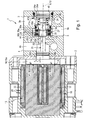
- einen Längsschnitt durch eine bevorzugte Ausführungsform der erfindungsgemäßen Ventileinrichtung in der ersten Schaltstellung des Verschlussabschnittes, der hier einer Grundstellung des Ventilgliedes entspricht,
Figur 2- einen Verfahrensschritt eines bevorzugten Herstellungsverfahrens zur Herstellung der Ventileinrichtung aus
Figur 1 , bei dem mittels eines nicht gezeigten Aufpresswerkzeuges eine durch einen Pfeil illustrierte Aufpresskraft in den Grundkörper des Verschlussabschnittes eingeleitet wird, und Figur 3- den in
Figur 2
- FIG. 1
- a longitudinal section through a preferred embodiment of the valve device according to the invention in the first switching position of the closure portion, which here corresponds to a basic position of the valve member,
- FIG. 2
- a method step of a preferred manufacturing method for producing the valve device
FIG. 1 in which by means of a pressing tool, not shown, a pressing force illustrated by an arrow is introduced into the main body of the closure portion, and - FIG. 3
- the in
FIG. 2 dash-dotted framed section in an alternative process sequence in which the pressing force illustrated by an arrow is introduced by means of an adjustable valve seat carrier in the main body of the closure portion.
Die insgesamt mit Bezugsziffer 1 bezeichnete Ventileinrichtung ist beim Ausführungsbeispiel als Mehrwegeventil mit einer 3/2-Ventilfunktion ausgebildet, stellt also mit anderen Worten ein 3/2-Mehrwegeventil dar.The total designated by reference numeral 1 valve device is formed in the embodiment as a multi-way valve with a 3/2-valve function, that is, in other words, a 3/2-way valve.
Die Ventileinrichtung 1 enthält ein Ventilgehäuse 2, an dem außen drei Ventilanschlüsse 3, 4, 5 ausgebildet sind, durch die ein Druckfluid, insbesondere Druckluft, hindurchleitbar ist.The valve device 1 contains a
Im Innern des Ventilgehäuses 2 befindet sich ein unter Ausführung einer durch einen Doppelpfeil angedeuteten Umschaltbewegung 6 linear in einer axialen Richtung hin und her bewegliches Ventilglied 7. Durch die Umschaltbewegung 6 kann das Ventilglied 7 wahlweise in einer aus
Das Ventilglied 7 erstreckt sich in einer im Innern des Ventilgehäuses 2 ausgebildeten, eine Längsachse 8 aufweisenden Aufnahmebohrung 9. Das Ventilglied 7 hat eine axiale Erstreckung mit einer Mittellängsachse 12, die mit der Längsachse 8 der Aufnahmebohrung 9 zusammenfällt.The
Einem der beiden axialen Endabschnitte des eine Längsgestalt aufweisenden Ventilgliedes 7 ist eine Elektromagneteinrichtung 13 zugeordnet. Die Elektromagneteinrichtung 13 verfügt über ein magnetisch leitfähiges Ankerelement 14, das bezüglich des Ventilgehäuses 2 axial beweglich ist und das als Bestandteil des Ventilgliedes 7 ausgebildet ist.One of the two axial end portions of the
Sofern im Folgenden von einer "axialen" Richtung die Rede ist, ist die Achsrichtung der Mittellängsachse 12 gemeint, sofern keine anderweitigen Angaben gemacht werden.If in the following an "axial" direction is mentioned, the axial direction of the central longitudinal axis 12 is meant, unless otherwise stated.
Das Ankerelement 14 bildet einen ersten axialen Endabschnitt 15a des Ventilgliedes 7.The
An den ersten axialen Endabschnitt 15a des Ventilgliedes 7 schließt sich axial eine elektrisch aktivierbare Steuereinheit 16 der Elektromagneteinrichtung 13 an. Diese Steuereinheit 16 enthält eine Flussleiteinrichtung 17 aus einem magnetisch leitenden Material, die beim Ausführungsbeispiel U-förmig gestaltet ist. Die Flussleiteinrichtung 17 verfügt über mindestens eine Polfläche 18, die dem Ankerelement 14 axial zugewandt ist. Aufgrund der U-förmigen Gestaltung weist die Flussleiteinrichtung 17 beim Ausführungsbeispiel zwei Polflächen 18 auf, die jeweils von der Stirnfläche eines der beiden U-Schenkel gebildet sind.An electrically
Auf der Flussleiteinrichtung 17 sitzt eine Spuleneinrichtung 22 der Elektromagneteinrichtung 13, die mittels von außen her zugänglichen elektromechanischen Kontaktmitteln 23 elektrisch bestrombar ist. Liegt an den Kontaktmitteln 23 keine Spannung an, ist die Elektromagneteinrichtung 13 deaktiviert. Durch Anlegen einer Spannung kann die Spuleneinrichtung 22 bestromt und mithin die Elektromagneteinrichtung 13 aktiviert werden, so dass sich ein Magnetfeld ausbildet, das eine magnetische Anziehungskraft FA auf das Ankerelement 14 ausübt, so dass das Ankerelement 14 in Richtung zu den Polflächen 18 herangezogen wird.On the
Das Ankerelement 14 ist zweckmäßigerweise ein längliches, plattenförmiges Gebilde.The
Durch die Anziehungskraft FA kann das Ventilglied 7 in die erste Schaltstellung verlagert werden. Bei deaktivierter Elektromagneteinrichtung 13 nimmt das Ventilglied 7 die erste Schaltstellung ein, in die es durch Federmittel 24 gedrückt wird. Es handelt sich hierbei vorzugsweise um mechanische Federmittel 24. Die Federmittel 24 wirken beim Ausführungsbeispiel zwischen dem Ventilglied 7 und einem noch zu erläuternden, sich am Ventilgehäuse 2 abstützenden Ventilsitzträger 45.By the attraction F A , the
In jeder Schaltstellung des Ventilgliedes 7 liegt zwischen dem Ankerelement 14 und der Steuereinheit 16 beziehungsweise den Polflächen 18 ein axialer Abstand "a" vor. Dieser axiale Abstand "a" ist in der ersten Schaltstellung größer als in der zweiten Schaltstellung. In keiner während des Betriebs der Ventileinrichtung 1 zwischen dem Ventilglied 7 und dem Ventilgehäuse 2 eingenommenen Relativposition ergibt sich ein mechanischer Kontakt zwischen dem Ankerelement 14 und der Steuereinheit 16. Stets ist hier ein axialer Abstand "a" vorhanden, der durch einen Luftspalt definiert ist. Der kleinste axiale Abstand "a" liegt in der zweiten Schaltstellung des Ventilgliedes 7 vor.In each switching position of the
Das Ventilglied 7 ist mehrteilig aufgebaut. Es enthält eine aufgrund ihrer Funktion als Antriebsabschnitt 25 bezeichnete Komponente, die über eine längliche Gestalt verfügt und deren Längsachse mit der Mittellängsachse 12 zusammenfällt. Das Ankerelement 14 ist ein Bestandteil des Antriebsabschnittes 25 und befindet sich an einem der Steuereinheit 16 zugewandten zweiten axialen Endabschnitt 26b des Antriebsabschnittes 25. Der gesamte Antriebsabschnitt 25 kann ein einstückiger Körper sein oder auch mehrteilig aus mehreren aneinander befestigten Komponenten zusammengesetzt sein. Beispielsweise kann das Ankerelement 14 an dem sich anschließenden Längenabschnitt des Antriebsabschnittes 25 durch eine Schraubverbindung fixiert sein.The
Als weitere Komponente enthält das Ventilglied 7 einen ringförmigen Verschlussabschnitt 27, der in einem Bereich auf dem Antriebsabschnitt 25 angeordnet ist, welcher zwischen dem das Ankerelement 14 aufweisenden zweiten axialen Endabschnitt 26b und dem diesbezüglich entgegengesetzten ersten axialen Endabschnitt 26a des Antriebsabschnittes 25 liegt. Der ringförmige Verschlussabschnitt 27 umschließt den Antriebsabschnitt 25 in konzentrischer Anordnung. Seine Längsachse fällt mit der Mittellängsachse 12 zusammen.As a further component, the
Der Verschlussabschnitt 27 ist derart an dem Antriebsabschnitt 25 befestigt, dass zwischen diesen beiden Komponenten während des normalen Betriebs der Ventileinrichtung 1 keine axiale Relativbewegung möglich ist. Die beiden Bestandteile sind also axial ortsfest aneinander fixiert.The
Der Verschlussabschnitt 27 ist in der axialen Richtung des Ventilgliedes 7 ohne Formschluss rein kraftschlüssig an dem Antriebsabschnitt 25 befestigt. Dies resultiert daraus, dass der Verschlussabschnitt 27 auf den Antriebsabschnitt 25 aufgepresst und dadurch im Presssitz auf dem Antriebsabschnitt 25 befestigt ist.The
Seitens des Verschlussabschnittes 27 bezieht sich die Presssitzverbindung auf einen aus einem starren Material bestehenden ringförmigen Grundkörper 28, der den Antriebsabschnitt 25 konzentrisch umschließt. Er besteht beispielsweise aus Metall oder aus einem Kunststoffmaterial.On the part of the
Der Antriebsabschnitt 25 verfügt über einen sich zwischen den beiden axialen Endabschnitten 26a, 26b erstreckenden stangenförmigen Mittelabschnitt 32. Dieser Mittelabschnitt 32 verfügt an einer zu den beiden axialen Endabschnitten 26a, 26b beabstandeten Stelle über einen radial erweiterten Befestigungsbund 33 mit einer bevorzugt kreiszylindrischen Außenumfangsfläche. Der Grundkörper 28 verfügt über eine zentrale Durchbrechung 34 mit einer bevorzugt ebenfalls kreiszylindrisch ausgebildeten Innenumfangsfläche. Die sich axial an den Befestigungsbund 33 anschließenden Längenabschnitte des Antriebsabschnittes 25 haben, zumindest zum ersten axialen Endabschnitt 26a hin und vorzugsweise auch zum zweiten axialen Endabschnitt 26b hin, einen kleineren Durchmesser als der Befestigungsbund 33.The
Vor der Montage auf dem Befestigungsbund 33 ist der Innendurchmesser des Grundkörpers 28 etwas kleiner als der Außendurchmesser des Befestigungsbundes 33. Der Verschlussabschnitt 27 kann gemäß
Der Verschlussabschnitt 27 hat eine von der Steuereinheit 16 axial abgewandte erste Stirnseite 35a und eine diesbezüglich axial entgegengesetzte, der Steuereinheit 16 zugewandte zweite Stirnseite 35b. Der Grundkörper 28 ist an der ersten Stirnseite 35a mit einem zu der Mittellängsachse 12 konzentrischen, ringförmigen ersten Abdichtabschnitt 36a versehen. An der entgegengesetzten zweiten Stirnseite 35b trägt der Grundkörper 28 einen zu der Mittellängsachse 12 ebenfalls konzentrischen, ringförmigen zweiten Abdichtabschnitt 36b. Beide Abdichtabschnitte sind gummielastisch verformbar ausgebildet und bestehen zweckmäßigerweise insgesamt aus einem Material mit gummielastischen Eigenschaften. Exemplarisch sind die beiden Abdichtabschnitte 36a, 36b aus Elastomermaterial gefertigt.The
Die Abdichtabschnitte 36a, 36b können prinzipiell außen auf den Grundkörper 28 aufgebracht sein. Vorteilhafter ist die beim Ausführungsbeispiel realisierte Anbringungsart, bei der der Grundkörper 28 an den beiden Stirnseiten 35a, 35b jeweils eine axial offene Ringnut 37a, 37b aufweist, in die der zugehörige Abdichtabschnitt 36a, 36b in Gestalt eines gummielastischen Abdichtmaterials eingesetzt ist. Der Verschlussabschnitt 37 hat an den beiden Stirnseiten 35a, 35b bevorzugt jeweils eine sich in einer bezüglich der Mittellängsachse 12 rechtwinkeligen Radialebene erstreckende Abschlussfläche, die sich teils am Grundkörper 28 und teils am zugehörigen Abdichtabschnitt 36a, 36b befindet.The sealing
Wie aus der Zeichnung gut ersichtlich ist, weisen die beiden Abdichtabschnitte 36a, 36b in einander entgegengesetzte axiale Richtungen voneinander weg.As can be clearly seen from the drawing, the two sealing
Dem ersten Abdichtabschnitt 36a liegt ein bezüglich des Ventilgehäuses 2 ortsfester erster Ventilsitz axial gegenüber. Dieser erste Ventilsitz 38a ist ringförmig ausgebildet und konzentrisch zu der Mittellängsachse 12 angeordnet. Er hat eine kragenartige Struktur, wobei er dem ersten Abdichtabschnitt 36a axial entgegenragt. Der erste Ventilsitz 38a weist also in Richtung zu der Steuereinheit 16.The
Dem zweiten Abdichtabschnitt 36b liegt ein ebenfalls bezüglich des Ventilgehäuses 2 ortsfester zweiter Ventilsitz 38b axial gegenüber. Auch dieser zweite Ventilsitz 38b ist ringförmig ausgebildet und konzentrisch zu der Mittellängsachse 12 angeordnet. Er ist außerdem kragenförmig strukturiert, wobei er dem zweiten Abdichtabschnitt 36b axial entgegenragt. Er weist also axial von der Steuereinheit 16 weg.The
Mithin liegt der Verschlussabschnitt 27 axial zwischen dem ersten Ventilsitz 38a und dem zweiten Ventilsitz 38b, die einander axial zugewandt sind.Thus, the
Der axiale Abstand zwischen den beiden Ventilsitzen 38a, 38b ist etwas größer als die axiale Länge des Verschlussabschnittes 27 im Bereich der beiden Abdichtabschnitte 36a, 36b. Auf diese Weise verfügt der Verschlussabschnitt 27 über eine axiale Bewegungsfreiheit bezüglich des Ventilgehäuses 2, die die Ausführung der Umschaltbewegung 6 ermöglicht. In der ersten Schaltstellung liegt der Verschlussabschnitt 27 mit dem ersten Abdichtabschnitt 36a unter Abdichtung am ersten Ventilsitz 38a an, wobei gleichzeitig der zweite Abdichtabschnitt 36b vom zweiten Ventilsitz 38b abgehoben ist. Umgekehrt liegt der zweite Abdichtabschnitt 36b in der zweiten Schaltstellung unter Abdichtung am zweiten Ventilsitz 38b an, wobei gleichzeitig der erste Abdichtabschnitt 36a vom ersten Ventilsitz 38a abgehoben ist.The axial distance between the two
Wie schon erwähnt, kann durch wahlweises Aktivieren und Deaktivieren der Elektromagneteinrichtung 13 die Umschaltbewegung 6 hervorgerufen und das Ventilglied 7 alternativ in der ersten Schaltstellung oder in der zweiten Schaltstellung positioniert werden.As already mentioned, can be caused by selectively activating and deactivating the
Bei dieser normalen Betriebsweise der Ventileinrichtung 1 kann das Ankerelement 14 niemals an der Steuereinheit 16 zur Anlage gelangen. Ein axialer Abstand "a" von größer Null ist also stets gewährleistet.In this normal operation of the valve device 1, the
Dadurch jedoch, dass die Abdichtabschnitte 36a, 36b über gummielastisch nachgiebige Eigenschaften verfügen, besteht prinzipiell die Möglichkeit, das Ventilglied 7 mit seinem Ankerelement 14 an die ihm zugewandte stirnseitige Endfläche 41 der Steuereinheit 16 anzudrücken, wenn nur die Drückkraft ausreichend groß ist, um die elastische Kraft des zweiten Abdichtabschnittes 36b, der an dem zweiten Ventilsitz 38b anliegt, zu überwinden. Ein solcher Zustand tritt während des normalen Betriebes der Ventileinrichtung 1 jedoch nicht auf, weil die von der Elektromagneteinrichtung 13 erzeugbare Anziehungskraft geringer ist als die Kraft, die notwendig ist, um den zweiten Abdichtabschnitt 36b so weit auf den zweiten Ventilsitz 38b aufzudrücken, dass das Ankerelement 14 an der stirnseitigen Endfläche 41 der Steuereinheit 16 zur Anlage gelangt.As a result, however, that the sealing
Beim Ausführungsbeispiel ist die stirnseitige Endfläche 41 durch die vorhandenen Polflächen 18 definiert.In the exemplary embodiment, the end-side end face 41 is defined by the existing pole faces 18.
Die bezüglich des Antriebsabschnittes 25 eingenommene axiale Relativposition des Verschlussabschnittes 27 zeichnet sich durch eine vorteilhafte Besonderheit aus. Diese Besonderheit besteht in einem speziellen Abstand zwischen dem Verschlussabschnitt 27 und dem Ankerelement 14. Dieser Abstand ist so gewählt, dass dann, wenn das Ankerelement 14 mit seiner der Steuereinheit 16 axial zugewandten äußeren Stirnfläche 42 an der stirnseitigen Endfläche 41 der Steuereinheit 16 anliegt, zugleich auch der Grundkörper 28 des Verschlussabschnittes 27 mit einer an seiner zweiten Stirnseite 35b ausgebildeten, axial orientierten Anschlagfläche 43 an einer bezüglich des Ventilgehäuses 2 ortsfesten Gegenanschlagfläche 44 zur Anlage gelangt. Dieser Zustand ist verbunden mit dem Umstand, dass zugleich der kragenförmige zweite Ventilsitz 38b weiter in den gummielastisch verformbaren zweiten Abdichtabschnitt 36b eingedrückt ist, als dies beim Normalbetrieb der Ventileinrichtung 1 möglich ist.The relative axial position of the
Die Anschlagfläche 43 ist der Steuereinheit 16 zugewandt, die Gegenanschlagfläche 44 weist axial von der Steuereinheit 16 weg.The stop face 43 faces the
Die Anschlagfläche 43 ist bevorzugt eine Ringfläche und bezüglich der Mittellängsachse 12 konzentrisch angeordnet. Sie liegt mit Bezug zur Mittellängsachse 12 radial neben dem zweiten Abdichtabschnitt 36b, wobei sie beim Ausführungsbeispiel den zweiten Abdichtabschnitt 36b radial außen konzentrisch umschließt.The
Konkret befindet sich die Anschlagfläche 43 beim Ausführungsbeispiel an dem sich radial außen an die den zweiten Abdichtabschnitt 36b aufnehmende Ringnut 37b anschließenden Abschnitt des Grundkörpers 28.Specifically, the
Die Gegenanschlagfläche 44 ist zweckmäßigerweise auch ringförmig ausgebildet und konzentrisch zu der Mittellängsachse 12 angeordnet. Sie ist zweckmäßigerweise ein einstückiger Bestandteil des Ventilgehäuses 2. Auch der zweite Ventilsitz 38b ist zweckmäßigerweise ein einstückiger Bestandteil des Ventilgehäuses 2. Die Anschlagfläche 43 und der zweite Ventilsitz 38b sind insgesamt bevorzugt einstückig miteinander ausgebildet.The
Auch der erste Ventilsitz 38a kann einstückig mit dem Ventilgehäuse 2 ausgebildet sein. Allerdings wird es als besonders vorteilhaft angesehen, wenn er, wie beim Ausführungsbeispiel, Bestandteil eines bezüglich des Ventilgehäuses 2 separaten und bezüglich des Ventilgehäuses 2 axial verstellbaren Ventilsitzträgers 45 ist. Während des normalen Betriebes der Ventileinrichtung 1 ist der Ventilsitzträger 45 allerdings bezüglich des Ventilgehäuses 2 axial unbeweglich fixiert. Die axiale Beweglichkeit ist für eine besonders einfache Art der Herstellung der Ventileinrichtung 1 und/oder für eine leichte Einstellung des Umschalthubes des Ventilgliedes 7 vorteilhaft.Also, the
Der Ventilsitzträger 45 ist zweckmäßigerweise hülsenförmig ausgebildet und in den der Steuereinheit 16 axial entgegengesetzten äußeren Endabschnitt 46 der Aufnahmebohrung 9 eingesetzt. Dabei umschließt er den auf der Seite des ersten Abdichtabschnittes 36a angeordneten ersten axialen Endabschnitt 26a des Antriebsabschnittes 25. Der erste Ventilsitz 38a befindet sich zweckmäßigerweise an der dem Verschlussabschnitt 27 zugewandten Stirnseite des Ventilsitzträgers 45 und ist insbesondere ein einstückiger Bestandteil des Ventilsitzträgers 45. Die beiden kragenförmigen, bezüglich radial benachbarten Bereichen jeweils axial erhaben ausgebildeten Ventilsitze 38a, 38b bestehen jedenfalls aus einer härteren Struktur als der zugeordnete elastische Abdichtabschnitt 36a, 36b.The
Um die axiale Verstellbarkeit des Ventilsitzträgers 45 zu realisieren, ist er zweckmäßigerweise in die Aufnahmebohrung 9 eingeschraubt. Beim Ausführungsbeispiel verfügt er zu diesem Zweck an seinem Außenumfang über ein Außengewinde 47a, das in ein Innengewinde 47b am Innenumfang des äußeren Endabschnittes 46 der Aufnahmebohrung 9 eingeschraubt ist.In order to realize the axial adjustability of the
Insbesondere wenn eine noch zu erläuternde besondere Art der Herstellung der Ventileinrichtung 1 realisiert werden soll, ist es von Vorteil, wenn der Ventilsitzträger 45 zusätzlich zu dem kragenförmigen ersten Ventilsitz 38a auch noch eine dem Grundkörper 28 gegenüberliegende und axial zugewandte weitere Anschlagfläche 48 aufweist, der eine an der ersten Stirnseite 35a an dem Grundkörper 28 ausgebildete weitere Gegenanschlagfläche 49 gegenüberliegt.In particular, if a still to be explained particular way of producing the valve device 1 is to be implemented, it is advantageous if the
Im Normalbetrieb der Ventileinrichtung 1 gelangen die weitere Anschlagfläche 48 und die weitere Gegenanschlagfläche 49 nicht in Kontakt miteinander. Ein gewisser Mindestabstand wird in der ersten Schaltstellung dadurch gewahrt, dass der Verschlussabschnitt 27 mit seinem ersten Abdichtabschnitt 36a an dem bezüglich der weiteren Anschlagfläche 48 axial vorstehenden ersten Ventilsitz 38a anliegt. An dieser Stelle sei noch angemerkt, dass in vergleichbarer Weise der kragenförmige zweite Ventilsitz 38b bezüglich der Gegenanschlagfläche 49 in Richtung zum Verschlussabschnitt 27 axial vorsteht.During normal operation of the valve device 1, the
Wird allerdings bei der Herstellung der Ventileinrichtung 1 eine ausreichend hohe Stellkraft in den Ventilsitzträger 45 eingeleitet, so dass dieser sich in Richtung zu dem Verschlussabschnitt 27 vorschraubt, ist der erste Ventilsitz 38a in den elastisch nachgiebigen ersten Abdichtabschnitt 36a eindrückbar, bis der Ventilsitzträger 45 mit der weiteren Anschlagfläche 48 an der weiteren Gegenanschlagfläche 49 anliegt.However, if a sufficiently high actuating force is introduced into the
Zum grundsätzlichen Ventilaufbau des Ausführungsbeispiels ist noch zu sagen, dass der erste Ventilsitz 38a eine erste Überströmöffnung 3a umrahmt und dass der zweite Ventilsitz 38b eine zweite Überströmöffnung 4a umrahmt. Beide Überströmöffnungen 3a, 4a sind axial orientiert, wobei die erste Überströmöffnung 3a über einen ersten Ventilkanal 3b zu dem ersten Ventilanschluss 3 führt und die zweite Überströmöffnung 4a über einen sich anschließenden zweiten Ventilkanal 4b zu dem zweiten Ventilanschluss 4 führt. Beide Ventilkanäle 3b, 4b erstrecken sich ein Stück weit in der axialen Richtung der Aufnahmebohrung 9, wobei der erste Ventilkanal 3b den mit einer partiell durchbrochenen Wandung versehenen Ventilsitzträger 45 durchsetzt.For the basic valve construction of the exemplary embodiment, it should also be stated that the
Der dritte Ventilanschluss 5 kommuniziert über einen dritten Ventilkanal 5b mit einer von der Aufnahmebohrung 9 definierten Ventilkammer 52, in der der Verschlussabschnitt 27 axial beweglich angeordnet ist. Diese Ventilkammer 52 ist axial einerseits vom Ventilgehäuse 2 und andererseits von dem Ventilsitzträger 45 begrenzt.The
Bei einer bevorzugten Art der Herstellung der Ventileinrichtung 1 wird das Ventilglied 7 mit seinem Grundkörper 28 axial in Richtung zu der Steuereinheit 16 auf den Antriebsabschnitt 25 aufgepresst, während sich dieser Antriebsabschnitt 25 mit seinem Ankerelement 14 an der stirnseitigen Endfläche 41 der Steuereinheit 16 - hier die Polfläche 18 - axial unbeweglich abstützt. Die oben erwähnte, für den Betrieb angestrebte axiale Relativposition zwischen dem Verschlussabschnitt 27 und dem Antriebsabschnitt 25 wird also in einem Zustand eingestellt, in dem der Antriebsabschnitt 25 bereits in die Aufnahmebohrung 9 eingesetzt ist.In a preferred mode of production of the valve device 1, the
Die zum Aufpressen des Verschlussabschnittes 27 erforderliche Aufpresskraft FP wird vorzugsweise in den Grundkörper 28 eingeleitet, worauf sich dieser Grundkörper 28 auf dem Befestigungsbund 33 axial in Richtung zu der Steuereinheit 16 verlagert. Die Relativbewegung bezüglich des Antriebsabschnittes 25 resultiert daraus, dass der Antriebsabschnitt 25 von der Steuereinheit 16 abgestützt ist.The pressing force F P required for pressing on the
Der Aufpressvorgang wird beendet, wenn der Grundkörper 28 mit seiner Anschlagfläche 43 an der Gegenanschlagfläche 44 des Ventilgehäuses 2 zur Anlage gelangt ist. Bei diesem Zustand ist außerdem, wie insbesondere aus
Anschließend wird die Aufpresskraft FP wieder weggenommen. Nun verändert sich die axiale Relativposition zwischen dem Grundkörper 28 und dem Antriebsabschnitt 25 nicht mehr, weil der Grundkörper 28 kraftschlüssig auf dem Antriebsabschnitt 25 befestigt ist.Subsequently, the pressing force F P is removed again. Now, the axial relative position between the main body 28 and the
Das Wegnehmen der Aufpresskraft FP hat allerdings wegen der rückfedernden Eigenschaften des elastischen zweiten Abdichtabschnittes 36b die Folge, dass der Grundkörper 28 von der Gegenanschlagfläche 44 abhebt. Wenn zu diesem Zeitpunkt die Federmittel 24 bereits montiert sind, wird dieses Abrücken von der Gegenanschlagfläche 44 selbstverständlich auch durch diese Federmittel 24 bewirkt.The removal of the pressing force F P has, however, because of the resilient properties of the elastic
Das Abrücken des Grundkörpers 28 von der Gegenanschlagfläche 44 hat wegen der kraftschlüssigen Verbindung zum Antriebsabschnitt 25 die zwangsläufige Folge, dass auch das Ankerelement 14 einen axialen Abstand "a", also eine Entfernung von größer Null bezüglich der stirnseitigen Endfläche 41 einnimmt.Due to the frictional connection to the
Für den späteren Betrieb der Ventileinrichtung 1 ist nun gewährleistet, dass das Ankerelement 14 in der zweiten Schließstellung des Ventilgliedes 7 nicht an der Steuereinheit 16 anschlagen kann.For the later operation of the valve device 1 is now ensured that the
Gemäß der Illustration in
In diesem Falle werden die weitere Anschlagfläche 48 und die weitere Gegenanschlagfläche 49 genutzt. Der Ventilsitzträger 45 wird in Richtung zur Steuereinheit 16 bewegt, bis er mit seiner weiteren Anschlagfläche 48 an der weiteren Gegenanschlagfläche 49 des Grundkörpers 28 anliegt und zugleich dieser Grundkörper 28 mit seiner Anschlagfläche 43 an der Gegenanschlagfläche 44 anliegt. In diesem Zustand haben sich beide Ventilsitze 38a, 38b in den ihnen zugeordneten Abdichtabschnitten 36a, 36b eingedrückt. Im Übrigen stützt sich hierbei das Ankerelement 14 wie oben beschrieben an der stirnseitigen Endfläche 41 der Steuereinheit 16 ab.In this case, the
Das anschließende Wegnehmen der Aufpresskraft geschieht durch axiales Zurückbewegen des Ventilsitzträgers 45, was beim Ausführungsbeispiel dadurch erfolgt, dass der Ventilsitzträger 45 ein Stück weit aus der Aufnahmebohrung 9 herausgeschraubt wird. Die entgegen der Aufpressrichtung stattfindende Zurückbewegung des Ventilsitzträgers 45 wird so weit vorgenommen, dass die beiden sich gegenüberliegenden Ventilsitze 38a, 38b einen den angestrebten Umschalthub des Ventilgliedes 7 vorgebenden axialen Abstand zueinander einnehmen.The subsequent removal of the pressing force is done by axially moving back the
Das Maß des axialen Wegbewegens des Ventilsitzträgers 45 vom zweiten Ventilsitz 38b entspricht insbesondere dem gewünschten Umschalthub zuzüglich der beim Aufpressvorgang auftretenden Eindrücktiefe der Ventilsitze 38a, 38b bezüglich der Abdichtabschnitte 36a, 36b.The extent of the axial movement away of the
Für die Schraubverbindung zwischen dem Ventilsitzträger 45 und dem Ventilgehäuse 2 wird zweckmäßigerweise auf eine Feingewindeanordnung zurückgegriffen. Dadurch ist eine sehr exakte Justierung möglich. Auch kann dadurch sehr einfach gewährleistet werden, dass die bezüglich des Ventilgehäuses 2 für den Normalbetrieb der Ventileinrichtung eingestellte Axialposition des Ventilsitzträgers 45 auch bei betrieblichen Erschütterungen keine Veränderung erfährt. Selbstverständlich ist es gleichwohl zweckmäßig, Sicherungsmaßnahmen vorzusehen, die ein unbeabsichtigtes axiales Verstellen des Ventilsitzträgers 45 verhindern. Hierzu kann beispielsweise ein Sicherungselement vorgesehen werden oder es wird ein Klebstoff zwischen dem Ventilgehäuse 2 und dem Ventilsitzträger 45 appliziert.For the screw connection between the
Claims (15)
Priority Applications (1)
| Application Number | Priority Date | Filing Date | Title |
|---|---|---|---|
| EP20120006846 EP2716946B1 (en) | 2012-10-02 | 2012-10-02 | Valve device and method for its production |
Applications Claiming Priority (1)
| Application Number | Priority Date | Filing Date | Title |
|---|---|---|---|
| EP20120006846 EP2716946B1 (en) | 2012-10-02 | 2012-10-02 | Valve device and method for its production |
Publications (2)
| Publication Number | Publication Date |
|---|---|
| EP2716946A1 true EP2716946A1 (en) | 2014-04-09 |
| EP2716946B1 EP2716946B1 (en) | 2014-09-17 |
Family
ID=47018715
Family Applications (1)
| Application Number | Title | Priority Date | Filing Date |
|---|---|---|---|
| EP20120006846 Active EP2716946B1 (en) | 2012-10-02 | 2012-10-02 | Valve device and method for its production |
Country Status (1)
| Country | Link |
|---|---|
| EP (1) | EP2716946B1 (en) |
Cited By (1)
| Publication number | Priority date | Publication date | Assignee | Title |
|---|---|---|---|---|
| CN112283401A (en) * | 2019-07-25 | 2021-01-29 | 费斯托股份两合公司 | Valve with a valve body |
Citations (7)
| Publication number | Priority date | Publication date | Assignee | Title |
|---|---|---|---|---|
| DE2826212A1 (en) * | 1977-06-18 | 1979-03-22 | Hart J C H | ACTUATION DEVICE |
| DE4000071A1 (en) * | 1990-01-03 | 1991-07-04 | Bosch Gmbh Robert | Compact bi-stable electromagnetic servo-valve for fluid flow control - has magnetised closure element driven by reversible winding current between I=O seatings |
| DE4117958A1 (en) * | 1991-05-31 | 1992-12-03 | Bosch Gmbh Robert | Magnetic valve with double U=shaped sections of core - has electromagnet coil wound on juxtaposed limbs of U=sections for significant redn. of stray leakage flux |
| DE19516885C1 (en) * | 1995-05-09 | 1996-10-24 | Elektroteile Gmbh | Air control valve in pneumatic system |
| DE19922089A1 (en) | 1999-05-17 | 2000-11-23 | Schrott Harald | Bistable electromagnetic valve |
| DE10307060A1 (en) | 2003-02-19 | 2004-09-16 | Aweco Appliance Systems Gmbh & Co. Kg | Valve |
| DE102007053503A1 (en) | 2007-11-09 | 2009-05-20 | Festo Ag & Co. Kg | Valve unit has valve head which for positional orientation on valve seat is pivotably mounted by ball joint, and valve pusher has tensioning device via which valve head can be fixed in rotationally-resistant manner on valve pusher |
-
2012
- 2012-10-02 EP EP20120006846 patent/EP2716946B1/en active Active
Patent Citations (7)
| Publication number | Priority date | Publication date | Assignee | Title |
|---|---|---|---|---|
| DE2826212A1 (en) * | 1977-06-18 | 1979-03-22 | Hart J C H | ACTUATION DEVICE |
| DE4000071A1 (en) * | 1990-01-03 | 1991-07-04 | Bosch Gmbh Robert | Compact bi-stable electromagnetic servo-valve for fluid flow control - has magnetised closure element driven by reversible winding current between I=O seatings |
| DE4117958A1 (en) * | 1991-05-31 | 1992-12-03 | Bosch Gmbh Robert | Magnetic valve with double U=shaped sections of core - has electromagnet coil wound on juxtaposed limbs of U=sections for significant redn. of stray leakage flux |
| DE19516885C1 (en) * | 1995-05-09 | 1996-10-24 | Elektroteile Gmbh | Air control valve in pneumatic system |
| DE19922089A1 (en) | 1999-05-17 | 2000-11-23 | Schrott Harald | Bistable electromagnetic valve |
| DE10307060A1 (en) | 2003-02-19 | 2004-09-16 | Aweco Appliance Systems Gmbh & Co. Kg | Valve |
| DE102007053503A1 (en) | 2007-11-09 | 2009-05-20 | Festo Ag & Co. Kg | Valve unit has valve head which for positional orientation on valve seat is pivotably mounted by ball joint, and valve pusher has tensioning device via which valve head can be fixed in rotationally-resistant manner on valve pusher |
Cited By (1)
| Publication number | Priority date | Publication date | Assignee | Title |
|---|---|---|---|---|
| CN112283401A (en) * | 2019-07-25 | 2021-01-29 | 费斯托股份两合公司 | Valve with a valve body |
Also Published As
| Publication number | Publication date |
|---|---|
| EP2716946B1 (en) | 2014-09-17 |
Similar Documents
| Publication | Publication Date | Title |
|---|---|---|
| EP1344949B1 (en) | Valve arrangement for a positioning cylinder | |
| EP3478957B1 (en) | Valve for injecting gaseous fuel | |
| EP0829668B1 (en) | Solenoid valve | |
| WO2017148776A1 (en) | Solenoid valve, in particular for a motor vehicle pneumatic suspension system | |
| EP2193298B1 (en) | Valve | |
| EP3698383B1 (en) | Electromagnetic actuator device and use of such a device | |
| EP2519732A1 (en) | Electromagnetically actuated volume control valve, in particular for controlling the delivery volume of a high-pressure fuel pump | |
| EP2716946B1 (en) | Valve device and method for its production | |
| DE102014220877B3 (en) | Fuel injection valve | |
| DE102004015661B4 (en) | Electro-pneumatic valve, in particular pilot valve for a pneumatic directional control valve | |
| DE102013018855A1 (en) | valve assembly | |
| WO2012034742A1 (en) | Normally closed magnetic valve | |
| DE102008005834B4 (en) | Valve device with manual override | |
| DE102019211004A1 (en) | Valve | |
| EP2853792B1 (en) | Device for regulating the flow of a fluid | |
| EP2228576B1 (en) | Valve device | |
| DE102004037269B3 (en) | Electro-pneumatic valve for piloting of directional valve has arms of flat spring having different lengths through which spring arms by lift movement of shut-off element come to bear one after other on different edges of armature step | |
| EP1752693B1 (en) | Solenoid actuated valve | |
| DE102013016548B3 (en) | Movable armature of a solenoid valve and solenoid valve equipped with it | |
| DE102004021528B4 (en) | Electro-pneumatic seat valve with an electromagnetic drive designed in the manner of the lifting armature system | |
| EP2110591A1 (en) | Valve | |
| DE10031873B4 (en) | Hydraulic valve | |
| DE102013110885A1 (en) | Valve | |
| WO2017186449A1 (en) | Electromagnetic valve and operating method | |
| DE10026081B4 (en) | Monostable directional valve |
Legal Events
| Date | Code | Title | Description |
|---|---|---|---|
| PUAI | Public reference made under article 153(3) epc to a published international application that has entered the european phase |
Free format text: ORIGINAL CODE: 0009012 |
|
| 17P | Request for examination filed |
Effective date: 20130312 |
|
| AK | Designated contracting states |
Kind code of ref document: A1 Designated state(s): AL AT BE BG CH CY CZ DE DK EE ES FI FR GB GR HR HU IE IS IT LI LT LU LV MC MK MT NL NO PL PT RO RS SE SI SK SM TR |
|
| AX | Request for extension of the european patent |
Extension state: BA ME |
|
| GRAP | Despatch of communication of intention to grant a patent |
Free format text: ORIGINAL CODE: EPIDOSNIGR1 |
|
| RIC1 | Information provided on ipc code assigned before grant |
Ipc: F16K 11/02 20060101AFI20140425BHEP Ipc: F16K 11/044 20060101ALI20140425BHEP Ipc: F16K 31/06 20060101ALI20140425BHEP |
|
| INTG | Intention to grant announced |
Effective date: 20140522 |
|
| GRAS | Grant fee paid |
Free format text: ORIGINAL CODE: EPIDOSNIGR3 |
|
| GRAA | (expected) grant |
Free format text: ORIGINAL CODE: 0009210 |
|
| AK | Designated contracting states |
Kind code of ref document: B1 Designated state(s): AL AT BE BG CH CY CZ DE DK EE ES FI FR GB GR HR HU IE IS IT LI LT LU LV MC MK MT NL NO PL PT RO RS SE SI SK SM TR |
|
| REG | Reference to a national code |
Ref country code: GB Ref legal event code: FG4D Free format text: NOT ENGLISH |
|
| REG | Reference to a national code |
Ref country code: CH Ref legal event code: EP |
|
| REG | Reference to a national code |
Ref country code: IE Ref legal event code: FG4D Free format text: LANGUAGE OF EP DOCUMENT: GERMAN |
|
| REG | Reference to a national code |
Ref country code: AT Ref legal event code: REF Ref document number: 687864 Country of ref document: AT Kind code of ref document: T Effective date: 20141015 |
|
| REG | Reference to a national code |
Ref country code: DE Ref legal event code: R096 Ref document number: 502012001246 Country of ref document: DE Effective date: 20141030 |
|
| PG25 | Lapsed in a contracting state [announced via postgrant information from national office to epo] |
Ref country code: SE Free format text: LAPSE BECAUSE OF FAILURE TO SUBMIT A TRANSLATION OF THE DESCRIPTION OR TO PAY THE FEE WITHIN THE PRESCRIBED TIME-LIMIT Effective date: 20140917 Ref country code: GR Free format text: LAPSE BECAUSE OF FAILURE TO SUBMIT A TRANSLATION OF THE DESCRIPTION OR TO PAY THE FEE WITHIN THE PRESCRIBED TIME-LIMIT Effective date: 20141218 Ref country code: NO Free format text: LAPSE BECAUSE OF FAILURE TO SUBMIT A TRANSLATION OF THE DESCRIPTION OR TO PAY THE FEE WITHIN THE PRESCRIBED TIME-LIMIT Effective date: 20141217 Ref country code: FI Free format text: LAPSE BECAUSE OF FAILURE TO SUBMIT A TRANSLATION OF THE DESCRIPTION OR TO PAY THE FEE WITHIN THE PRESCRIBED TIME-LIMIT Effective date: 20140917 Ref country code: LT Free format text: LAPSE BECAUSE OF FAILURE TO SUBMIT A TRANSLATION OF THE DESCRIPTION OR TO PAY THE FEE WITHIN THE PRESCRIBED TIME-LIMIT Effective date: 20140917 |
|
| REG | Reference to a national code |
Ref country code: NL Ref legal event code: VDEP Effective date: 20140917 |
|
| REG | Reference to a national code |
Ref country code: LT Ref legal event code: MG4D |
|
| PG25 | Lapsed in a contracting state [announced via postgrant information from national office to epo] |
Ref country code: HR Free format text: LAPSE BECAUSE OF FAILURE TO SUBMIT A TRANSLATION OF THE DESCRIPTION OR TO PAY THE FEE WITHIN THE PRESCRIBED TIME-LIMIT Effective date: 20140917 Ref country code: RS Free format text: LAPSE BECAUSE OF FAILURE TO SUBMIT A TRANSLATION OF THE DESCRIPTION OR TO PAY THE FEE WITHIN THE PRESCRIBED TIME-LIMIT Effective date: 20140917 Ref country code: LV Free format text: LAPSE BECAUSE OF FAILURE TO SUBMIT A TRANSLATION OF THE DESCRIPTION OR TO PAY THE FEE WITHIN THE PRESCRIBED TIME-LIMIT Effective date: 20140917 Ref country code: CY Free format text: LAPSE BECAUSE OF FAILURE TO SUBMIT A TRANSLATION OF THE DESCRIPTION OR TO PAY THE FEE WITHIN THE PRESCRIBED TIME-LIMIT Effective date: 20140917 |
|
| PG25 | Lapsed in a contracting state [announced via postgrant information from national office to epo] |
Ref country code: NL Free format text: LAPSE BECAUSE OF FAILURE TO SUBMIT A TRANSLATION OF THE DESCRIPTION OR TO PAY THE FEE WITHIN THE PRESCRIBED TIME-LIMIT Effective date: 20140917 |
|
| PG25 | Lapsed in a contracting state [announced via postgrant information from national office to epo] |
Ref country code: PT Free format text: LAPSE BECAUSE OF FAILURE TO SUBMIT A TRANSLATION OF THE DESCRIPTION OR TO PAY THE FEE WITHIN THE PRESCRIBED TIME-LIMIT Effective date: 20150119 Ref country code: ES Free format text: LAPSE BECAUSE OF FAILURE TO SUBMIT A TRANSLATION OF THE DESCRIPTION OR TO PAY THE FEE WITHIN THE PRESCRIBED TIME-LIMIT Effective date: 20140917 Ref country code: EE Free format text: LAPSE BECAUSE OF FAILURE TO SUBMIT A TRANSLATION OF THE DESCRIPTION OR TO PAY THE FEE WITHIN THE PRESCRIBED TIME-LIMIT Effective date: 20140917 Ref country code: SK Free format text: LAPSE BECAUSE OF FAILURE TO SUBMIT A TRANSLATION OF THE DESCRIPTION OR TO PAY THE FEE WITHIN THE PRESCRIBED TIME-LIMIT Effective date: 20140917 Ref country code: RO Free format text: LAPSE BECAUSE OF FAILURE TO SUBMIT A TRANSLATION OF THE DESCRIPTION OR TO PAY THE FEE WITHIN THE PRESCRIBED TIME-LIMIT Effective date: 20140917 Ref country code: CZ Free format text: LAPSE BECAUSE OF FAILURE TO SUBMIT A TRANSLATION OF THE DESCRIPTION OR TO PAY THE FEE WITHIN THE PRESCRIBED TIME-LIMIT Effective date: 20140917 Ref country code: IS Free format text: LAPSE BECAUSE OF FAILURE TO SUBMIT A TRANSLATION OF THE DESCRIPTION OR TO PAY THE FEE WITHIN THE PRESCRIBED TIME-LIMIT Effective date: 20150117 |
|
| PG25 | Lapsed in a contracting state [announced via postgrant information from national office to epo] |
Ref country code: PL Free format text: LAPSE BECAUSE OF FAILURE TO SUBMIT A TRANSLATION OF THE DESCRIPTION OR TO PAY THE FEE WITHIN THE PRESCRIBED TIME-LIMIT Effective date: 20140917 |
|
| REG | Reference to a national code |
Ref country code: DE Ref legal event code: R097 Ref document number: 502012001246 Country of ref document: DE |
|
| PG25 | Lapsed in a contracting state [announced via postgrant information from national office to epo] |
Ref country code: BE Free format text: LAPSE BECAUSE OF NON-PAYMENT OF DUE FEES Effective date: 20141031 Ref country code: MC Free format text: LAPSE BECAUSE OF FAILURE TO SUBMIT A TRANSLATION OF THE DESCRIPTION OR TO PAY THE FEE WITHIN THE PRESCRIBED TIME-LIMIT Effective date: 20140917 |
|
| PLBE | No opposition filed within time limit |
Free format text: ORIGINAL CODE: 0009261 |
|
| STAA | Information on the status of an ep patent application or granted ep patent |
Free format text: STATUS: NO OPPOSITION FILED WITHIN TIME LIMIT |
|
| REG | Reference to a national code |
Ref country code: IE Ref legal event code: MM4A |
|
| PG25 | Lapsed in a contracting state [announced via postgrant information from national office to epo] |
Ref country code: DK Free format text: LAPSE BECAUSE OF FAILURE TO SUBMIT A TRANSLATION OF THE DESCRIPTION OR TO PAY THE FEE WITHIN THE PRESCRIBED TIME-LIMIT Effective date: 20140917 |
|
| 26N | No opposition filed |
Effective date: 20150618 |
|
| REG | Reference to a national code |
Ref country code: FR Ref legal event code: PLFP Year of fee payment: 4 |
|
| PG25 | Lapsed in a contracting state [announced via postgrant information from national office to epo] |
Ref country code: IE Free format text: LAPSE BECAUSE OF NON-PAYMENT OF DUE FEES Effective date: 20141002 |
|
| PG25 | Lapsed in a contracting state [announced via postgrant information from national office to epo] |
Ref country code: SI Free format text: LAPSE BECAUSE OF FAILURE TO SUBMIT A TRANSLATION OF THE DESCRIPTION OR TO PAY THE FEE WITHIN THE PRESCRIBED TIME-LIMIT Effective date: 20140917 |
|
| REG | Reference to a national code |
Ref country code: CH Ref legal event code: PL |
|
| PG25 | Lapsed in a contracting state [announced via postgrant information from national office to epo] |
Ref country code: BG Free format text: LAPSE BECAUSE OF FAILURE TO SUBMIT A TRANSLATION OF THE DESCRIPTION OR TO PAY THE FEE WITHIN THE PRESCRIBED TIME-LIMIT Effective date: 20140917 |
|
| PG25 | Lapsed in a contracting state [announced via postgrant information from national office to epo] |
Ref country code: HU Free format text: LAPSE BECAUSE OF FAILURE TO SUBMIT A TRANSLATION OF THE DESCRIPTION OR TO PAY THE FEE WITHIN THE PRESCRIBED TIME-LIMIT; INVALID AB INITIO Effective date: 20121002 Ref country code: LI Free format text: LAPSE BECAUSE OF NON-PAYMENT OF DUE FEES Effective date: 20151031 Ref country code: CH Free format text: LAPSE BECAUSE OF NON-PAYMENT OF DUE FEES Effective date: 20151031 Ref country code: MT Free format text: LAPSE BECAUSE OF FAILURE TO SUBMIT A TRANSLATION OF THE DESCRIPTION OR TO PAY THE FEE WITHIN THE PRESCRIBED TIME-LIMIT Effective date: 20140917 Ref country code: TR Free format text: LAPSE BECAUSE OF FAILURE TO SUBMIT A TRANSLATION OF THE DESCRIPTION OR TO PAY THE FEE WITHIN THE PRESCRIBED TIME-LIMIT Effective date: 20140917 Ref country code: LU Free format text: LAPSE BECAUSE OF NON-PAYMENT OF DUE FEES Effective date: 20141002 |
|
| REG | Reference to a national code |
Ref country code: FR Ref legal event code: PLFP Year of fee payment: 5 |
|
| PG25 | Lapsed in a contracting state [announced via postgrant information from national office to epo] |
Ref country code: SM Free format text: LAPSE BECAUSE OF FAILURE TO SUBMIT A TRANSLATION OF THE DESCRIPTION OR TO PAY THE FEE WITHIN THE PRESCRIBED TIME-LIMIT Effective date: 20140917 |
|
| REG | Reference to a national code |
Ref country code: FR Ref legal event code: PLFP Year of fee payment: 6 |
|
| PGFP | Annual fee paid to national office [announced via postgrant information from national office to epo] |
Ref country code: GB Payment date: 20170824 Year of fee payment: 6 |
|
| PG25 | Lapsed in a contracting state [announced via postgrant information from national office to epo] |
Ref country code: MK Free format text: LAPSE BECAUSE OF FAILURE TO SUBMIT A TRANSLATION OF THE DESCRIPTION OR TO PAY THE FEE WITHIN THE PRESCRIBED TIME-LIMIT Effective date: 20140917 |
|
| REG | Reference to a national code |
Ref country code: FR Ref legal event code: PLFP Year of fee payment: 7 |
|
| PG25 | Lapsed in a contracting state [announced via postgrant information from national office to epo] |
Ref country code: AL Free format text: LAPSE BECAUSE OF FAILURE TO SUBMIT A TRANSLATION OF THE DESCRIPTION OR TO PAY THE FEE WITHIN THE PRESCRIBED TIME-LIMIT Effective date: 20140917 |
|
| REG | Reference to a national code |
Ref country code: AT Ref legal event code: MM01 Ref document number: 687864 Country of ref document: AT Kind code of ref document: T Effective date: 20171002 |
|
| PG25 | Lapsed in a contracting state [announced via postgrant information from national office to epo] |
Ref country code: AT Free format text: LAPSE BECAUSE OF NON-PAYMENT OF DUE FEES Effective date: 20171002 |
|
| PGFP | Annual fee paid to national office [announced via postgrant information from national office to epo] |
Ref country code: FR Payment date: 20181023 Year of fee payment: 7 Ref country code: IT Payment date: 20181022 Year of fee payment: 7 |
|
| GBPC | Gb: european patent ceased through non-payment of renewal fee |
Effective date: 20181002 |
|
| PG25 | Lapsed in a contracting state [announced via postgrant information from national office to epo] |
Ref country code: GB Free format text: LAPSE BECAUSE OF NON-PAYMENT OF DUE FEES Effective date: 20181002 |
|
| REG | Reference to a national code |
Ref country code: DE Ref legal event code: R082 Ref document number: 502012001246 Country of ref document: DE Representative=s name: PATENTANWAELTE MAGENBAUER & KOLLEGEN PARTNERSC, DE Ref country code: DE Ref legal event code: R081 Ref document number: 502012001246 Country of ref document: DE Owner name: FESTO SE & CO. KG, DE Free format text: FORMER OWNER: FESTO AG & CO. KG, 73734 ESSLINGEN, DE Ref country code: DE Ref legal event code: R081 Ref document number: 502012001246 Country of ref document: DE Owner name: FESTO AG & CO. KG, DE Free format text: FORMER OWNER: FESTO AG & CO. KG, 73734 ESSLINGEN, DE |
|
| PG25 | Lapsed in a contracting state [announced via postgrant information from national office to epo] |
Ref country code: FR Free format text: LAPSE BECAUSE OF NON-PAYMENT OF DUE FEES Effective date: 20191031 Ref country code: IT Free format text: LAPSE BECAUSE OF NON-PAYMENT OF DUE FEES Effective date: 20191002 |
|
| PGFP | Annual fee paid to national office [announced via postgrant information from national office to epo] |
Ref country code: DE Payment date: 20230920 Year of fee payment: 12 |