EP2716897A1 - Vehicle control device - Google Patents
Vehicle control device Download PDFInfo
- Publication number
- EP2716897A1 EP2716897A1 EP11866991.0A EP11866991A EP2716897A1 EP 2716897 A1 EP2716897 A1 EP 2716897A1 EP 11866991 A EP11866991 A EP 11866991A EP 2716897 A1 EP2716897 A1 EP 2716897A1
- Authority
- EP
- European Patent Office
- Prior art keywords
- clutch
- speed
- time period
- engine
- waiting time
- Prior art date
- Legal status (The legal status is an assumption and is not a legal conclusion. Google has not performed a legal analysis and makes no representation as to the accuracy of the status listed.)
- Granted
Links
Images




Classifications
-
- F—MECHANICAL ENGINEERING; LIGHTING; HEATING; WEAPONS; BLASTING
- F02—COMBUSTION ENGINES; HOT-GAS OR COMBUSTION-PRODUCT ENGINE PLANTS
- F02N—STARTING OF COMBUSTION ENGINES; STARTING AIDS FOR SUCH ENGINES, NOT OTHERWISE PROVIDED FOR
- F02N11/00—Starting of engines by means of electric motors
- F02N11/08—Circuits specially adapted for starting of engines
- F02N11/0814—Circuits specially adapted for starting of engines comprising means for controlling automatic idle-start-stop
- F02N11/0818—Conditions for starting or stopping the engine or for deactivating the idle-start-stop mode
- F02N11/0822—Conditions for starting or stopping the engine or for deactivating the idle-start-stop mode related to action of the driver
-
- B—PERFORMING OPERATIONS; TRANSPORTING
- B60—VEHICLES IN GENERAL
- B60W—CONJOINT CONTROL OF VEHICLE SUB-UNITS OF DIFFERENT TYPE OR DIFFERENT FUNCTION; CONTROL SYSTEMS SPECIALLY ADAPTED FOR HYBRID VEHICLES; ROAD VEHICLE DRIVE CONTROL SYSTEMS FOR PURPOSES NOT RELATED TO THE CONTROL OF A PARTICULAR SUB-UNIT
- B60W10/00—Conjoint control of vehicle sub-units of different type or different function
- B60W10/04—Conjoint control of vehicle sub-units of different type or different function including control of propulsion units
- B60W10/06—Conjoint control of vehicle sub-units of different type or different function including control of propulsion units including control of combustion engines
-
- B—PERFORMING OPERATIONS; TRANSPORTING
- B60—VEHICLES IN GENERAL
- B60W—CONJOINT CONTROL OF VEHICLE SUB-UNITS OF DIFFERENT TYPE OR DIFFERENT FUNCTION; CONTROL SYSTEMS SPECIALLY ADAPTED FOR HYBRID VEHICLES; ROAD VEHICLE DRIVE CONTROL SYSTEMS FOR PURPOSES NOT RELATED TO THE CONTROL OF A PARTICULAR SUB-UNIT
- B60W30/00—Purposes of road vehicle drive control systems not related to the control of a particular sub-unit, e.g. of systems using conjoint control of vehicle sub-units
- B60W30/18—Propelling the vehicle
- B60W30/18009—Propelling the vehicle related to particular drive situations
- B60W30/18018—Start-stop drive, e.g. in a traffic jam
-
- B—PERFORMING OPERATIONS; TRANSPORTING
- B60—VEHICLES IN GENERAL
- B60W—CONJOINT CONTROL OF VEHICLE SUB-UNITS OF DIFFERENT TYPE OR DIFFERENT FUNCTION; CONTROL SYSTEMS SPECIALLY ADAPTED FOR HYBRID VEHICLES; ROAD VEHICLE DRIVE CONTROL SYSTEMS FOR PURPOSES NOT RELATED TO THE CONTROL OF A PARTICULAR SUB-UNIT
- B60W2540/00—Input parameters relating to occupants
- B60W2540/10—Accelerator pedal position
-
- B—PERFORMING OPERATIONS; TRANSPORTING
- B60—VEHICLES IN GENERAL
- B60W—CONJOINT CONTROL OF VEHICLE SUB-UNITS OF DIFFERENT TYPE OR DIFFERENT FUNCTION; CONTROL SYSTEMS SPECIALLY ADAPTED FOR HYBRID VEHICLES; ROAD VEHICLE DRIVE CONTROL SYSTEMS FOR PURPOSES NOT RELATED TO THE CONTROL OF A PARTICULAR SUB-UNIT
- B60W2540/00—Input parameters relating to occupants
- B60W2540/14—Clutch pedal position
-
- F—MECHANICAL ENGINEERING; LIGHTING; HEATING; WEAPONS; BLASTING
- F02—COMBUSTION ENGINES; HOT-GAS OR COMBUSTION-PRODUCT ENGINE PLANTS
- F02N—STARTING OF COMBUSTION ENGINES; STARTING AIDS FOR SUCH ENGINES, NOT OTHERWISE PROVIDED FOR
- F02N2200/00—Parameters used for control of starting apparatus
- F02N2200/08—Parameters used for control of starting apparatus said parameters being related to the vehicle or its components
- F02N2200/0802—Transmission state, e.g. gear ratio or neutral state
-
- F—MECHANICAL ENGINEERING; LIGHTING; HEATING; WEAPONS; BLASTING
- F02—COMBUSTION ENGINES; HOT-GAS OR COMBUSTION-PRODUCT ENGINE PLANTS
- F02N—STARTING OF COMBUSTION ENGINES; STARTING AIDS FOR SUCH ENGINES, NOT OTHERWISE PROVIDED FOR
- F02N2200/00—Parameters used for control of starting apparatus
- F02N2200/10—Parameters used for control of starting apparatus said parameters being related to driver demands or status
- F02N2200/101—Accelerator pedal position
-
- F—MECHANICAL ENGINEERING; LIGHTING; HEATING; WEAPONS; BLASTING
- F02—COMBUSTION ENGINES; HOT-GAS OR COMBUSTION-PRODUCT ENGINE PLANTS
- F02N—STARTING OF COMBUSTION ENGINES; STARTING AIDS FOR SUCH ENGINES, NOT OTHERWISE PROVIDED FOR
- F02N2200/00—Parameters used for control of starting apparatus
- F02N2200/10—Parameters used for control of starting apparatus said parameters being related to driver demands or status
- F02N2200/103—Clutch pedal position
-
- F—MECHANICAL ENGINEERING; LIGHTING; HEATING; WEAPONS; BLASTING
- F02—COMBUSTION ENGINES; HOT-GAS OR COMBUSTION-PRODUCT ENGINE PLANTS
- F02N—STARTING OF COMBUSTION ENGINES; STARTING AIDS FOR SUCH ENGINES, NOT OTHERWISE PROVIDED FOR
- F02N2300/00—Control related aspects of engine starting
- F02N2300/20—Control related aspects of engine starting characterised by the control method
- F02N2300/2011—Control involving a delay; Control involving a waiting period before engine stop or engine start
-
- Y—GENERAL TAGGING OF NEW TECHNOLOGICAL DEVELOPMENTS; GENERAL TAGGING OF CROSS-SECTIONAL TECHNOLOGIES SPANNING OVER SEVERAL SECTIONS OF THE IPC; TECHNICAL SUBJECTS COVERED BY FORMER USPC CROSS-REFERENCE ART COLLECTIONS [XRACs] AND DIGESTS
- Y02—TECHNOLOGIES OR APPLICATIONS FOR MITIGATION OR ADAPTATION AGAINST CLIMATE CHANGE
- Y02T—CLIMATE CHANGE MITIGATION TECHNOLOGIES RELATED TO TRANSPORTATION
- Y02T10/00—Road transport of goods or passengers
- Y02T10/10—Internal combustion engine [ICE] based vehicles
- Y02T10/40—Engine management systems
Definitions
- the present invention relates to a vehicle control device in which an engine is connected to a manual transmission via a clutch.
- double clutch operations may be performed to adjust an engine rotation speed in speed shifting.
- double clutch operations for example, the following seven operations (first to seventh operations) are performed sequentially within a prescribed time period.
- a clutch pedal is stepped to put a clutch into a disengaged state (first operation), and a shift lever is moved to a neutral position to put the manual transmission into a neutral state (second operation).
- the stepped clutch pedal is released to put the clutch into an engaged state (third operation), and in this state, the engine rotation speed is suitably increased by flapping an accelerator pedal (fourth operation).
- the clutch pedal is stepped again to put the clutch into the disengaged state (fifth operation), and the sift lever is moved to a shift position corresponding to a desirable speed stage (sixth operation).
- the stepped clutch pedal is released again to put the clutch into the engaged state (seventh operation), and thus, the speed change is completed.
- the operations to stop the engine may be the same as the first-third operations of the above-described double clutch operations.
- the engine stop may be executed against a driver's intention to perform the double clutch operations. That is, since the engine stop operations cannot be distinguished from the double clutch operations, the speed change by the double clutch operations may be interrupted by executing the engine stop after completion of the third operation, thereby speed change responsiveness may be degraded.
- the present invention was made in consideration of such circumstances, and an object thereof is to provide an vehicle control device capable of stopping the engine, during travel of the vehicle, without preventing the double clutch operation.
- the present invention has the following configuration for solving the above-described problem. That is, the present invention provides a vehicle control device that is applied to a vehicle on which are mounted an engine, a manual transmission and a clutch that is provided between the engine and the manual transmission and that is capable of switching a disengaged state and an engaged state.
- the vehicle control device includes an engine stop unit controlling an engine stop during travel of the vehicle, in which the engine stop unit performs the engine stop when a prescribed waiting time period elapses after sequential execution of an operation to put the clutch into the disengaged state, an operation to put a gear stage of the manual transmission into a neutral state and an operation to put the clutch into the engaged state.
- the engine stop is not performed immediately after completion of the operation to put the clutch into the engaged state during travel of the vehicle, but is performed when the waiting time period elapses. Therefore, during travel of the vehicle, the engine can be stopped without preventing the double clutch operations for adjusting the engine rotation speed in the speed change. That is, the engine can be stopped by the engine stop unit independently from the speed change by the double clutch operations. Thus, the vehicle can travel with the engine being stopped. Furthermore, the speed change by the double clutch operations can be performed smoothly, without interruption, so as to ensure speed change responsiveness.
- the engine stop unit suspends engine stop control if a suspending condition for suspending the engine stop control is satisfied before the elapse of the waiting time period.
- the suspending condition may be a stepping operation of an accelerator pedal, or a stepping operation of a clutch pedal.
- the stop control of the engine is suspended.
- the accelerator pedal stepping operation is performed before the elapse of the waiting time period, such an accelerator operation is considered to be an adjusting operation of the engine rotation speed for the speed change, thus the engine stop control is suspended to not stop the engine.
- the engine stop control is suspended according to the driver's intention, thereby the speed change by the double clutch operations can be performed smoothly, without interruption, so as to ensure speed change responsiveness.
- the waiting time period is set to be longer than the waiting time period when the operation speed is low.
- the operation speed to put the clutch into the disengaged state e.g. to step the clutch pedal
- the waiting time period is set to be longer than the waiting time period when the operation speed is low.
- the waiting time period is set based on the operation speed to put the clutch into the disengaged state, thereby, the engine stop operations are surely distinguished from the double clutch operations. Therefore, it is possible to reliably eliminate interruption, against the driver's intention, of the speed change using the "double clutch operations".
- the waiting time period is set to be longer than the waiting time period when the operation speed is low.
- the operation speed to put the gear stage of the manual transmission into the neutral state e.g. to move the shift lever to the neutral position
- the waiting time period is set to be longer than the waiting time period when the operation speed is low.
- the waiting time period is set based on the operation speed to put the gear stage of the manual transmission into the neutral state, thereby, the engine stop operations are surely distinguished from the double clutch operations. Therefore, it is possible to reliably eliminate interruption, against the driver's intention, of the speed change using the "double clutch operations".
- the waiting time period is set to be longer than the waiting time period when the operation speed is low.
- the operation speed to put the clutch into the engaged state e.g. to release the stepped clutch pedal
- the waiting time period is set to be longer than the waiting time period when the operation speed is low.
- the waiting time period is set based on the operation speed to put the clutch into the engaged state, thereby, the engine stop operations are surely distinguished from the double clutch operations. Therefore, it is possible to reliably eliminate interruption, against the driver's intention, of the speed change using the "double clutch operations".
- the waiting time period is set to be longer than the waiting time period when the vehicle speed is high.
- the waiting time period is set to be longer than the waiting time period when the vehicle speed is high.
- the waiting time period is set based on the vehicle speed, thereby, the engine stop operations are surely distinguished from the double clutch operations. Therefore, it is possible to reliably eliminate interruption, against the driver's intention, of the speed change using the "double clutch operations".
- the engine stop is not performed immediately after completion of the operation to put the clutch into the engaged state during travel of the vehicle, but is performed when the waiting time period elapses. Therefore, during travel of the vehicle, the engine can be stopped without preventing the double clutch operations for adjusting the engine rotation speed in the speed change. That is, the engine can be stopped by the engine stop unit independently from the speed change using the double clutch operations. Thus, the vehicle can travel with the engine being stopped. Furthermore, the speed change by the double clutch operations can be performed smoothly, without interruption, so as to ensure speed change responsiveness.
- FIG. 1 is a diagram showing a schematic configuration of a vehicle according to an embodiment of the present invention.
- the vehicle shown in FIG. 1 is an FR (front-engine rear-wheel-drive) vehicle that includes an engine 1 as a drive power source, a manual transmission 2, a clutch device 3, a shift device 5, an accelerator pedal 6, a clutch pedal 7 and the like.
- a drive force (drive torque) generated by the engine 1 is input into the manual transmission 2 from a crankshaft 15, which is an output shaft of the engine 1, via the clutch device 3.
- the torque input into the manual transmission 2 is subjected to speed change at an appropriate speed change ratio by the manual transmission 2, and is output from an output shaft 22 (see FIG. 3 ).
- the torque output from the output shaft 22 is transmitted to right and left rear wheels (driving wheels) 44, 44 via a propeller shaft 41, a differential gear 42 and axles 43, 43.
- each component of the vehicle will be described.
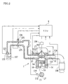
- FIG. 2 is a diagram showing a schematic configuration of the engine 1 mounted on the vehicle of FIG. 1 .
- the engine 1 is, for example, a multi-cylinder gasoline engine, and includes, as shown in FIG. 2 , a piston 1b that forms a combustion chamber 1a, and the crankshaft 15 as an output shaft.
- the piston 1b is coupled with the crankshaft 15 via a connecting rod 16. Reciprocating movement of the piston 1b is converted into rotational movement of the crankshaft 15 by the connecting rod 16.
- the crankshaft 15 is provided with a signal rotor 17. On the outer periphery of the signal rotor 17, a plurality of the projections 17a is formed at regular intervals. In a vicinity of a side of the signal rotor 17, an engine speed sensor 124 is disposed.
- the engine speed sensor 124 is, for example, an electromagnetism pickup, and generates pulse signals (output pulses) in accordance with the number of the projections 17a that pass over a position opposite to the engine speed sensor 124 as the crankshaft 15 is rotated.
- a cylinder block 1c of the engine 1 includes a water temperature sensor 121 that detects an engine water temperature (cooling water temperature).
- An ignition plug 103 is disposed in the combustion chamber 1a of the engine 1. An ignition timing of the ignition plug 103 is adjusted by an igniter 104. The igniter 104 is controlled by an ECU 8.
- an intake path 11 and an exhaust path 12 are connected to the combustion chamber 1a.
- An intake valve 13 is provided between the intake path 11 and the combustion chamber 1a.
- the intake valve 13 is driven to open and close so as to communicate and disconnect between the intake path 11 and the combustion chamber 1a.
- An exhaust valve 14 is provided between the exhaust path 12 and the combustion chamber 1a.
- the exhaust valve 14 is driven to open and close so as to communicate and disconnect between the exhaust path 12 and the combustion chamber 1a.
- the open/close drive of the intake valve 13 and the exhaust valve 14 is performed by respective rotations of an intake cam shaft and an exhaust cam shaft (not shown) to which the rotation of the crankshaft 15 is transmitted.
- the intake path 11 is provided with an air cleaner 107, an airflow meter 122, an intake air temperature sensor 123, an electronically controlled throttle valve 105 that adjusts an amount of intake air of the engine 1, and the like.
- the exhaust path 12 is provided with an O 2 sensor 127 that detects an oxygen concentration in an exhaust gas, a three-way catalyst 108, and the like.
- the throttle valve 105 is driven by a throttle motor 106.
- an opening degree of the throttle valve 105 (throttle opening degree) is adjusted, and the amount of intake air of the engine 1 is adjusted according to the throttle opening degree.
- the throttle opening degree is detected by a throttle opening degree sensor 125.
- the throttle motor 106 is driven and controlled by the ECU 8.
- the intake path 11 is provided with an injector (fuel injection valve) 102.
- the injector 102 is supplied with fuel having a predetermined pressure from a fuel tank (not shown) via a fuel pump, and then the fuel is injected to the intake path 11 by the injector 102.
- the fuel injected by the injector 102 is mixed with the intake air into air-fuel mixture gas, and introduced into the combustion chamber 1a of the engine 1.
- the mixture gas (fuel and air) introduced into the combustion chamber 1a is ignited by the ignition plug 103 for combustion and explosion.
- the combustion and explosion of the mixture gas in the combustion chamber 1a causes reciprocating movement of the piston 1b, thereby the crankshaft 15 is driven to rotate.
- FIG. 3 is a skeleton diagram showing a schematic configuration of the manual transmission 2 mounted on the vehicle of FIG. 1 .
- the manual transmission 2 is a well-known synchro-mesh manual transmission (for example, six forward shift stages and one backward shift stage). As shown in FIG. 3 , an input shaft 21 is coupled with the crankshaft 15 of the engine 1 via the clutch device 3. Also, the output shaft 22 is coupled with the propeller shaft 41 (see FIG. 1 ). By this manual transmission 2, the drive torque from the engine 1 is subjected to speed change at a prescribed speed change ratio, and then transmitted to the rear wheel 44, 44 side.
- the manual transmission 2 includes six forward shift stages 201 to 206 that differ in a speed change ratio (gear ratio), one backward shift stage 207, a synchro-mesh mechanism 24A for the first-second speed shift, a synchro-mesh mechanism 24B for the third-fourth speed shift, a synchro-mesh mechanism 24C for the fifth-sixth speed shift and the like.
- the forward shift gear stages 201 to 206 are formed of combination of respective drive gears 211 to 216 mounted on the input shaft 21 side and respective driven gears 221 to 226 mounted on the output shaft 22 side.
- the drive gears 211 to 216 mesh respectively with the driven gears 221 to 226.
- the respective drive gears 211 and 212 of the first speed and the second speed are mounted on the input shaft 21 in a manner integrally rotatable therewith.
- the respective drive gears 213 to 216 of the third to sixth speeds are relatively rotatably mounted on the input shaft 21 via respective bearings (for example, cage and roller).
- the respective driven gears 221 and 222 of the first speed and the second speed are relatively rotatably mounted on the output shaft 22 via respective bearings (for example, cage and roller).
- the respective driven gears 223 to 226 are mounted on the output shaft 22 in a manner integrally rotatable therewith.
- the backward shift gear stage 207 includes a reverse drive gear 217, a reverse driven gear 227, a reverse idler gear 237 and the like.
- the synchro-mesh mechanisms 24A, 24B and 24C each have a well-known configuration, and detailed description thereof is omitted.
- the synchro-mesh mechanisms 24A, 24B and 24C each have substantially the same configuration, i.e. have a sleeve 241, a synchronizer ring, a clutch hub and the like, which are not shown in detail in the figure.
- the sleeve 241 is slid in the axial direction by a shift fork (not shown) of the manual transmission 2.
- the shift fork is operated so as to establish a shift stage corresponding to a shift position selected by manipulating a shift lever 501 (see FIG. 1 ) of the shift device 5.
- the shift lever 501 is mechanically coupled with the shift fork via cables, links and the like.
- the shift position selected by the shift lever 501 is detected by a shift position sensor 502 (see FIG. 1 ) provided in the manual transmission 2.
- the shift position sensor 502 may be provided in a vicinity of the shift lever 501.
- shift pattern shift gate shape
- a shift gate that is disposed on a floor in a vehicle cabin and configured to guide a movement of the shift lever 501 of the shift device 5.
- FIG. 4 schematically shows the shift pattern of the manual transmission 2 having six forward shift stages and one backward shift stage.
- the shift lever 501 can perform select manipulation in a direction indicated by an arrow X shown in FIG. 4 and shift manipulation in a direction indicated by an arrow Y orthogonal to the direction of the select manipulation.
- a first-speed and second-speed select position P1 In the select manipulation direction, a first-speed and second-speed select position P1, a third-speed and fourth-speed select position P2, a fifth-speed and sixth-speed select position P3 and a reverse select position P4 are arranged in a row.
- the shift lever 501 can be moved to a first speed position 1st or a second speed position 2nd.
- the sleeve 241 of the synchro-mesh mechanism 24A for the first-second speed change of the manual transmission 2 is operated to an establishment side of the first speed (the right side in FIG. 3 ), thus establishing the first speed stage.
- the sleeve 241 of the synchro-mesh mechanism 24A for the first-second speed change is operated to an establishment side of the second speed (the left side in FIG. 3 ), thus establishing the second speed stage.
- the shift lever 501 can be moved to a third speed position 3rd or a fourth speed position 4th.
- the sleeve 241 of the synchro-mesh mechanism 24B for the third-fourth speed change of the manual transmission 2 is operated to an establishment side of the third speed (the right side in FIG. 3 ), thus establishing the third speed stage.
- the shift lever 501 is moved to the fourth speed position 4th, the sleeve 241 of the synchro-mesh mechanism 24B for the third-fourth speed change is operated to an establishment side of the fourth speed (the left side in FIG. 3 ), thus establishing the fourth speed stage.
- the shift lever 501 can be moved to a fifth speed position 5th or a sixth speed position 6th.
- the shift lever 501 is moved to the fifth speed position 5th, the sleeve 241 of the synchro-mesh mechanism 24C for the fifth-sixth speed change of the manual transmission 2 is operated to an establishment side of the fifth speed (the right side in FIG. 3 ), thus establishing the fifth speed stage.
- the shift lever 501 is moved to the sixth speed position 6th, the sleeve 241 of the synchro-mesh mechanism 24C for the fifth-sixth speed change is operated to an establishment side of the sixth speed (the left side in FIG. 3 ), thus establishing the sixth speed stage.
- the shift lever 501 can be moved to a reverse position REV.
- the synchro-mesh mechanisms 24A, 24B and 24C of the manual transmission 2 are each turned into a neutral state, and the reverse idler gear 237 of the manual transmission 2 is actuated, thus establishing the backward shift stage.
- the third-speed and fourth-speed select position P2 serves as the neutral position.
- the shift lever 501 is moved to the neutral position P2
- the synchro-mesh mechanisms 24A, 24B and 24C of the manual transmission 2 are each turned into a neutral state, thus the manual transmission 2 is turned into a neutral state in which no torque is transmitted between the input shaft 21 and the output shaft 22.
- FIG. 5 is a diagram showing a schematic configuration of the clutch device 3 mounted on the vehicle of FIG. 1 .
- the clutch device 3 includes a clutch mechanism 30 (simply referred to as “clutch 30") and a clutch actuating device 300 that actuates the clutch 30 in response to a stepping operation of the clutch pedal 7.
- the clutch 30 is configured as a dry-type single plate friction clutch, and is disposed so as to be interposed between the crankshaft 15 and the input shaft 21 of the manual transmission 2. It is possible to adopt the clutch 30 other than the dry-type single plate friction clutch.
- the clutch 30 includes a flywheel 31, a clutch disc 32, a pressure plate 33, a diaphragm spring 34 and a clutch cover 35.
- the flywheel 31 and the clutch cover 35 are integrally rotatably attached to the crankshaft 15 that serves as the input shaft of the clutch 30.
- the clutch disc 32 is splined to the input shaft 21 of the manual transmission 2 as the output shaft of the cultch 30. For this reason, the clutch disc 32 is integrally rotated with the input shaft 21, while it is slidable in the axial direction (left and right direction in FIG. 5 ).
- the pressure plate 33 is provided between the clutch disc 32 and the clutch cover 35. The pressure plate 33 is biased toward the flywheel 31 by the outer periphery portion of the diaphragm spring 34.
- the clutch actuating device 300 includes a release bearing 301, a release fork 302, a clutch release cylinder 303, a clutch master cylinder 304 and the like.
- the release bearing 301 is slidably attached to the input shaft 21 in the axial direction.
- the release fork 302 is rotatably supported by a shaft 302a, one end portion (lower end portion in FIG. 5 ) of which makes contact with the release bearing 301.
- the other end portion (upper end portion in FIG. 5 ) of the release fork 302 is coupled with one end portion (right end portion in FIG. 5 ) of a rod 303a of the clutch release cylinder 303.
- the clutch release cylinder 303 has a configuration in which a piston 303c and the like are incorporated in a cylinder body 303b.
- the piston 303c is coupled with the other end portion (left end portion in FIG. 5 ) of the rod 303a.
- the clutch release cylinder 303 is coupled with the clutch master cylinder 304 via an oil pressure pipe 305.
- the clutch master cylinder 304 has a configuration in which a piston 304c and the like are incorporated in a cylinder body 304b.
- the piston 304c is coupled with one end portion (left end portion in FIG. 5 ) of a rod 304a.
- the other end portion (right end portion in FIG. 5 ) of the rod 304a is coupled with an intermediate portion of a pedal lever 71 of the clutch pedal 7.
- a reserve tank 304d is disposed on the upper portion of the cylinder body 304b.
- the reserve tank 304d supplies a clutch fluid (oil) serving as a working fluid into the cylinder body 304b.
- the clutch master cylinder 304 generates oil pressure by movement of the piston 304c in the cylinder body 304b upon receipt of operation force by a stepping operation of the clutch pedal 7 by a driver.
- the oil pressure generated by the clutch master cylinder 304 is transmitted through oil in the oil pressure pipe 305 to the clutch release cylinder 303.
- the release fork 302 is actuated according to the oil pressure in the clutch release cylinder 303, thereby engaging and disengaging the clutch 30.
- the clutch 30 is put into a connected (engaged) state (clutch engaged state) by the frictional force.
- the clutch engaged state the pressure plate 33, the clutch disc 32 and the flywheel 31 are integrally rotated. Accordingly, the crankshaft 15 and the input shaft 21 are integrally rotated, thus torque is transmitted between the engine 1 and the manual transmission 2.
- a pedal upper switch 72 and a pedal lower switch 73 Adjacent to the pedal lever 71 of the clutch pedal 7, a pedal upper switch 72 and a pedal lower switch 73 are disposed.
- the pedal upper switch 72 and the pedal lower switch 73 detect whether or not the stepping amount of the clutch pedal 7 by the driver reaches a prescribed amount. Specifically, the pedal upper switch 72 outputs a signal "ON” if the stepping of the clutch pedal 7 is released until it reaches the position where the clutch 30 is put into the engaged state.
- the pedal lower switch 73 outputs a signal "ON” if the clutch pedal 7 is stepped until it reaches the position where the clutch 30 is put into the disengaged state.
- the ECU 8 performs various kinds of control for the engine 1 and the like.
- the ECU 8 includes, as shown in FIG. 6 , a CPU 81, a ROM 82, a RAM 83, a backup RAM 84, an input interface 85, an output interface 86 and the like.
- the ROM 82 stores various control programs, maps referred to at the time of executing those various control programs, and the like.
- the CPU 81 executes calculation processing based on the various control programs and the maps stored in the ROM 82.
- the RAM 83 is a memory that temporary stores caluculation results in the CPU 81 and data input from various sensors, various switches, and the like.
- the backup RAM 84 is a non-volatile memory that stores data and the like that should be stored when the engine 1 is stopped.
- the CPU 81, the ROM 82, the RAM 83 and the backup RAM 84 are connected to each other via a bus 87, and also connected to the input interface 85 and the output interface 86.
- the input interface 85 is connected to the pedal upper switch 72, the pedal lower switch 73, the water temperature sensor 121, the airflow meter 122, the intake air temperature sensor 123, the engine speed sensor 124, the throttle opening degree sensor 125, the O 2 sensor 126, and the like. Also, the input interface 85 is connected to an accelerator opening degree sensor 61, a wheel speed sensor 431 and the shift position sensor 502 and the like.
- the accelerator opening degree sensor 61 is provided adjacent to the accelerator pedal 6 (see FIG. 1 ) and detects the stepping amount (accelerator opening degree) of the accelerator pedal 6 by a driver.
- the wheel speed sensor 431 is provided adjacent to the axle 43 (see FIG. 1 ) and detects the vehicle speed.
- the shift position sensor 502 detects a shift position selected by the shift lever 501 (see FIG. 1 ) of the shift device 5.
- the output interface 86 is connected to the injector 102, the igniter 104 of the ignition plug 103, the throttle motor 106 of the throttle valve 105, and the like.
- the ECU 8 executes, based on outputs from the above various sensors and switches, various kinds of control for the vehicle including drive control (fuel injection control) for the injector 102, ignition timing control for the ignition plug 103 and drive control for the throttle motor 106 of the throttle valve 105. Also, the ECU 8 executes the following engine stop control.
- This embodiment is characterized in that, during travel of the vehicle, in a case where a prescribed waiting time period T1 is elapsed after a prescribed "engine stop operations" have been performed, the engine 1 is stopped.
- a prescribed waiting time period T1 is elapsed after a prescribed "engine stop operations" have been performed.
- the first operation putting the clutch 30 into the disengaged state (OFF);
- the second operation putting the gear stage of the manual transmission 2 into the neutral state (N); and
- the third operation putting the clutch 30 into the engaged state (ON).
- a time period from completion of the first operation to a start of the second operation be within a prescribed first time period (for example, 5 seconds)
- a time period from completion of the second operation to a start of the third operation be within a prescribed second time period (for example, 5 seconds).
- the first operation is an operation stepping the clutch pedal 7 by a driver. It is possible to determine whether or not the first operation is completed based on output from the pedal lower switch 73. Specifically, it is determined that the first operation is completed when the signal "ON" is output from the pedal lower switch 73. On the other hand, it is determined that the first operation is not completed when the signal "OFF" is output from the pedal lower switch 73.
- the second operation is an operation moving (returning) the shift lever 501 of the shift device 5, by the driver, from any position of the first speed 1st to sixth speed 6th to the neutral position P2. It is possible to determine whether or not the second operation is completed based on output from the shift position sensor 502.
- the third operation is an operation releasing the stepped clutch pedal 7 by the driver. It is possible to determine whether or not the third operation is completed based on output from the pedal upper switch 72. Specifically, it is determined that the third operation is completed when the signal "ON" is output from the pedal upper switch 72. On the other hand, it is determined that the third operation is not completed when the signal "OFF" is output from the pedal upper switch 72.
- the above first operation to the third operation are sequentially operated, thereby the gear stage of the manual transmission 2 is turned into the neutral state and the engine 1 is stopped while the clutch 30 is engaged.
- the engine 1 can be stopped in a suitable state without affecting the travel of the vehicle.
- the driver can maintain such a state (the state in which the engine 1 is being stopped) with his/her foot being away from the clutch pedal 7, thus burden with respect to driving operation by the driver can be reduced.
- the control routine indicated in FIG. 7 is repeatedly performed at a prescribed time period (for example, several milliseconds to several tens of milliseconds) by the ECU 8.
- step S101 it is determined whether or not the vehicle is traveling. This determination can be performed based on output from the wheel speed sensor 431. If the result in step S101 is YES, the processing advances to step S102. If the result in step S101 is NO, the processing is set to a standby state.
- step S102 it is determined whether or not the above-described "engine stop operations" are performed during travel of the vehicle. In this case, it is determined whether or not the first to third operations are performed sequentially within the prescribed time period. If the result in step S102 is YES, the processing advances to step S103. If the result in step S102 is NO, the processing returns.
- step S103 it is determined whether or not the prescribed waiting time period T1 elapses after it is determined that the "engine stop operations" are performed in step S102. That is, a timer of the ECU 8 is started at the time of completion of the third operation of the "engine stop operations” to measure an elapsed time from the point when the third operation is completed. Then, it is determined whether or not the measured time by the timer reaches the waiting time period T1.
- step S103 If the result in step S103 is YES, the processing advances to step S104. If the result in step S103 is NO, the processing is set to the standby state.
- step S104 the engine 1 is stopped. After that, the timer of the ECU 8 is reset and the control routine is terminated. Note that the travel of the vehicle with the engine 1 being stopped is continued until specified operations (for example, stepping of the accelerator pedal 6, stepping of the clutch pedal 7 and the like) are performed to cancel the stopped state of the engine 1.
- specified operations for example, stepping of the accelerator pedal 6, stepping of the clutch pedal 7 and the like
- the engine 1 is not stopped immediately after the "engine stop operations" are performed, but is stopped after the waiting time period T1 elapses. Therefore, in this embodiment, during travel of the vehicle, the stop of the engine 1 can be performed without preventing the "double clutch operations" to adjust, in the speed change, the rotation speed of the engine 1 to the rotation speed after the speed change. The following is description concerning this point.
- double clutch operations for example, the following first to seventh operations are performed sequentially within a prescribed time period.
- the first operation putting the clutch 30 into the disengaged state (OFF);
- the second operation putting the gear stage of the manual transmission 2 into the neutral state (N);
- the third operation putting the clutch 30 into the engaged state (ON);
- the fourth operation adjusting the rotation speed of the engine 1 by the accelerator pedal 6;
- the fifth operation putting again the clutch 30 into the disengaged state (OFF);
- the sixth operation operating the shift lever 501 to a shift position corresponding to a desirable speed stage; and
- the seventh operation putting again the clutch 30 into the engaged state (ON).
- the engine 1 may be stopped against the driver's intention of performing the "double clutch operations” and may result in interruption of the speed change operations of the "double clutch operations".
- the engine 1 is stopped after elapse of the waiting time period T1 following completion of the third operation.
- the waiting time period T1 is set so as to distinguish the "engine stop operations" from the “double clutch operations".
- the "double clutch operations” are operations to adjust the rotation speed of the engine 1 in the speed change.
- the above first to seventh operations are generally performed within a relatively short time period. Therefore, in the "double clutch operations", it is likely that the fourth operation is performed immediately after completion of the third operation.
- the waiting time period T1 is set to a time period (for example, 0.5 second) in which there is no possibility of performing the fourth operation of the "double clutch operations" after completion of the third operation in view of the speed change responsiveness.
- the waiting time period T1 is set to the time period in which, if the fourth operation of the "double clutch operations" is performed when the waiting time period T1 elapses after completion of the third operation, the speed change responsiveness is impaired. That is, after completion of the third operation, the engine 1 is not stopped within the waiting time period T1 in which there is possibility of performing the fourth operation of the "double clutch operations", so that the "engine stop operations" are surely distinguished from the “double clutch operations".
- the waiting time period T1 As follows. Description will be given with specific examples (1) to (3).
- the waiting time period T1 is set to be longer than that when the operation speed is low.
- the operation speed of the stepping operation of the clutch pedal 7 can be calculated based on outputs of the pedal upper switch 72 and the pedal lower switch 73. In this case, the operation speed of the stepping operation of the clutch pedal 7 is calculated based on a required time from the point when the signal "OFF" is output from the pedal upper switch 72 (the point when the signal "ON” is switched to “OFF") to the point when the signal "ON” is output from the pedal lower switch 73 (the point when the signal "OFF” is switched to "ON”).
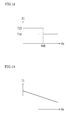
- the waiting time period T1 can be set according to the operation speed Vp of the clutch pedal 7 using a map shown in FIG. 8 . Specifically, if the operation speed Vp of the clutch pedal 7 is higher than a prescribed threshold value Vp0, the waiting time period T1 is set to T11. In contrast, if the operation speed Vp of the clutch pedal 7 is equal to or less than the threshold value Vp0, the waiting time period T1 is set to T12 that is shorter than T11. Or, the waiting time period T1 can be set to be proportionally longer as the operation speed Vp of the clutch pedal 7 is higher, using a map shown in FIG. 9 .
- the maps in FIGS. 8 and 9 , and the threshold value Vp0 are preliminarily stored in the ROM 82 of the ECU 8.
- the waiting time period T1 may also be set to be longer than that when the operation speed is low.
- the waiting time period T1 can be set using maps similar to those in FIGS. 8 and 9 .
- the operation speed of the releasing operation of the stepped clutch pedal 7 can be calculated based on a required time from the point when the signal "OFF" is output from the pedal lower switch 73 (the point when the signal "ON” is switched to “OFF") to the point when the signal "ON” is output from the pedal upper switch 72 (the point when the signal "OFF” is switched to “ON”).
- the operation speed of the shift lever 501 by the driver is higher, there is a high possibility of the "double clutch operations". For this reason, if the operation speed of moving the shift lever 501 from any position of the first speed 1st to sixth speed 6th to the neutral position P2 is high (i.e. the operation speed of the second operation is high), the waiting time period T1 is set to be longer than that when the operation speed is low.
- the operation speed of the shift lever 501 can be calculated based on output of the shift position sensor 502.
- the waiting time period T1 can be set according to the operation speed Vs of the shift lever 501 using a map shown in FIG. 10 . Specifically, if the operation speed Vs of the shift lever 501 is higher than a prescribed threshold value Vs0, the waiting time period T1 is set to T13. In contrast, if the operation speed Vs of the shift lever 501 is equal to or less than the threshold value Vs0, the waiting time period T1 is set to T14 that is shorter than T13. Or, the waiting time period T1 can be set to be proportionally longer as the operation speed Vp of the clutch pedal 7 is higher, using a map shown in FIG. 11 .
- the maps in FIGS. 10 and 11 , and the threshold value Vs0 are preliminarily stored in the ROM 82 of the ECU 8.
- the waiting time period T1 is set to be longer than that when the vehicle speed is high.
- the vehicle speed can be calculated based on output of the wheel speed sensor 431. In this case, it is possible to use the vehicle speed at the time when the shift lever 501 is moved to the neutral position P2, i.e. the vehicle speed at the time of completion of the second operation.
- the waiting time period T1 can be set according to the vehicle speed Vv using a map shown in FIG. 12 . Specifically, if the vehicle speed Vv is lower than a prescribed threshold value Vv0, the waiting time period T1 is set to T15. In contrast, if the vehicle speed Vv is equal to or more than the threshold value Vv0, the waiting time period T1 is set to T16 that is shorter than T15. Or, the waiting time period T1 can be set to be proportionally shorter as the vehicle speed Vv is higher, using a map shown in FIG. 13 .
- the maps in FIGS. 12 and 13 , and the threshold value Vv0 are preliminarily stored in the ROM 82 of the ECU 8.
- the waiting time period T1 is set based on the operation speed of the clutch pedal 7, the operation speed of the shift lever 501, or the vehicle speed.
- the "engine stop operations” are surely distinguished from the “double clutch operations”. Therefore, it is possible to reliably eliminate interruption, against the driver's intention, of the speed change using the "double clutch operations".
- the waiting time period T1 can be set by combination of the plurality of examples (1) to (3).
- the suspending condition can be, for example, the stepping operation of the accelerator pedal 6, or the stepping operation of the clutch pedal 7.
- the suspending condition is the stepping operation of the accelerator pedal 6.
- steps S201 to S204 in the flowchart of FIG. 14 the processing similar to steps S101 to S104 in the flowchart of FIG. 7 of the above-described embodiment is performed.
- step S203 if the result in step S203 is NO in the flowchart of FIG. 14 , to be specific, if a measured time by the timer of the ECU 8 has not reached the waiting time period T1, the processing advances to step S205.
- step S205 it is determined whether or not the stepping operation of the accelerator pedal 6 has been performed. That is, it is determined whether or not the suspending condition has been satisfied. This determination can be performed based on output of the accelerator opening degree sensor 61 that detects the amount of stepping of the accelerator pedal.
- step S205 If the result in step S205 is NO, the processing returns to step S203. If the waiting time period T1 elapses after completion of the third operation without accelerator operation, the engine 1 is stopped in step S204.
- step S205 If the result in step S205 is YES, the control routine is terminated without stopping the engine 1 in step S204. If the accelerator is operated before elapse of the waiting time period T1 following the completion of the third operation, the stop operation of the engine 1 is not performed in step S204.
- the accelerator operation before the elapse of the waiting time period T1 is determined to be an adjusting operation of the rotation speed of the engine 1 for the speed change (i.e. the above-described fourth operation of the "double clutch operations"), and if such an accelerator operation is performed, the engine stop control is suspended so that the engine 1 is not stopped. In this way, the engine stop control is suspended according to the driver's intention, thereby the speed change by the "double clutch operations" can be performed smoothly, without interruption, so as to ensure speed change responsiveness.
- the stepping operation and the releasing operation of the stepped clutch pedal 7 are detected by the pedal upper switch 72 and the pedal lower switch 73.
- the present invention should not be limited thereto.
- the amount of the stepping of the clutch pedal 7 may be detected using a stroke sensor and the like.
- the shift position sensor 502 is provided to detect a shift position of the shift lever 501.
- the shift position sensor 502 detects that the shift lever 501 is moved to the neutral position P2.
- a neutral switch and the like may detect that the shift lever 501 is moved to the neutral position P2.
- the neutral switch has, for example, a configuration to output a signal "ON” when the shift lever 501 is moved to the neutral position P2, and output a signal “OFF” when the shift lever 501 is moved to a position other than the neutral position P2.
- the timer of the ECU 8 is started at the time when the third operation (operation to put the clutch 30 into the engaged state) is completed so as to determine whether or not the waiting time period T1 elapses.
- the timer of the ECU 8 may be started at the time when the second operation (operation to put the gear stage of the manual transmission 2 into the neutral state) is completed.
- control of the FR (front-engine rear-wheel-drive) vehicle to which the present invention is applied.
- the present invention should not be limited thereto.
- the present invention may be applied to control of various vehicles such as an FF (front-engine front-wheel-drive) vehicle, and 4WD (four-wheel-drive) vehicle.
- the present invention is suitable for use in a vehicle on which mounted an engine, a manual transmission and a clutch that is provided between the engine and the manual transmission and that is capable of shifting between an engaged state and a disengaged state, the vehicle controlling an engine stop during travel.
Landscapes
- Engineering & Computer Science (AREA)
- Chemical & Material Sciences (AREA)
- Combustion & Propulsion (AREA)
- Mechanical Engineering (AREA)
- Transportation (AREA)
- General Engineering & Computer Science (AREA)
- Automation & Control Theory (AREA)
- Control Of Vehicle Engines Or Engines For Specific Uses (AREA)
- Output Control And Ontrol Of Special Type Engine (AREA)
- Hydraulic Clutches, Magnetic Clutches, Fluid Clutches, And Fluid Joints (AREA)
Abstract
Description
- The present invention relates to a vehicle control device in which an engine is connected to a manual transmission via a clutch.
- In a vehicle including a manual transmission, so-called double clutch operations may be performed to adjust an engine rotation speed in speed shifting. In the double clutch operations, for example, the following seven operations (first to seventh operations) are performed sequentially within a prescribed time period.
- First, a clutch pedal is stepped to put a clutch into a disengaged state (first operation), and a shift lever is moved to a neutral position to put the manual transmission into a neutral state (second operation). Next, the stepped clutch pedal is released to put the clutch into an engaged state (third operation), and in this state, the engine rotation speed is suitably increased by flapping an accelerator pedal (fourth operation). After adjusting the engine rotation speed, the clutch pedal is stepped again to put the clutch into the disengaged state (fifth operation), and the sift lever is moved to a shift position corresponding to a desirable speed stage (sixth operation). The stepped clutch pedal is released again to put the clutch into the engaged state (seventh operation), and thus, the speed change is completed. By performing the double clutch operations, it is possible to suppress a shifting shock during travel while reducing burden of a synchro-mesh mechanism and the like in the manual transmission.
- Also, with a vehicle including a manual transmission, technology has been proposed in which fuel consumption is improved by stopping an engine when a clutch is in a disengaged state and furthermore the shift position is in a neutral state, and starting the engine when the shift position has changed from the neutral state to a travel position (See, for example, Patent Literature 1).
-
- [Patent Literature 1]
JP H11-257119A - [Patent Literature 2]
JP 2005-163762A - However, in the vehicle that travels with the engine being stopped by carrying out the above-described engine stop, the operations to stop the engine (engine stop operations) may be the same as the first-third operations of the above-described double clutch operations. Thus, after completion of the third operation, the engine stop may be executed against a driver's intention to perform the double clutch operations. That is, since the engine stop operations cannot be distinguished from the double clutch operations, the speed change by the double clutch operations may be interrupted by executing the engine stop after completion of the third operation, thereby speed change responsiveness may be degraded.
- The present invention was made in consideration of such circumstances, and an object thereof is to provide an vehicle control device capable of stopping the engine, during travel of the vehicle, without preventing the double clutch operation.
- The present invention has the following configuration for solving the above-described problem. That is, the present invention provides a vehicle control device that is applied to a vehicle on which are mounted an engine, a manual transmission and a clutch that is provided between the engine and the manual transmission and that is capable of switching a disengaged state and an engaged state. The vehicle control device includes an engine stop unit controlling an engine stop during travel of the vehicle, in which the engine stop unit performs the engine stop when a prescribed waiting time period elapses after sequential execution of an operation to put the clutch into the disengaged state, an operation to put a gear stage of the manual transmission into a neutral state and an operation to put the clutch into the engaged state.
- In the above vehicle control device, the engine stop is not performed immediately after completion of the operation to put the clutch into the engaged state during travel of the vehicle, but is performed when the waiting time period elapses. Therefore, during travel of the vehicle, the engine can be stopped without preventing the double clutch operations for adjusting the engine rotation speed in the speed change. That is, the engine can be stopped by the engine stop unit independently from the speed change by the double clutch operations. Thus, the vehicle can travel with the engine being stopped. Furthermore, the speed change by the double clutch operations can be performed smoothly, without interruption, so as to ensure speed change responsiveness.
- In the vehicle control device having the above configuration, preferably the engine stop unit suspends engine stop control if a suspending condition for suspending the engine stop control is satisfied before the elapse of the waiting time period. Here, the suspending condition may be a stepping operation of an accelerator pedal, or a stepping operation of a clutch pedal.
- In the vehicle control device having the above configuration, if the suspending condition is satisfied before the elapse of waiting time period, the stop control of the engine is suspended. For example, if the accelerator pedal stepping operation is performed before the elapse of the waiting time period, such an accelerator operation is considered to be an adjusting operation of the engine rotation speed for the speed change, thus the engine stop control is suspended to not stop the engine. In this way, the engine stop control is suspended according to the driver's intention, thereby the speed change by the double clutch operations can be performed smoothly, without interruption, so as to ensure speed change responsiveness.
- In the vehicle control device having the above configuration, preferably, when an operation speed to put the clutch into the disengaged state is high, the waiting time period is set to be longer than the waiting time period when the operation speed is low.
- In the vehicle control device having the above configuration, as the operation speed to put the clutch into the disengaged state (e.g. to step the clutch pedal) is higher, there is a high possibility of the double clutch operations. For this reason, when the operation speed is high, the waiting time period is set to be longer than the waiting time period when the operation speed is low. Thus, the waiting time period is set based on the operation speed to put the clutch into the disengaged state, thereby, the engine stop operations are surely distinguished from the double clutch operations. Therefore, it is possible to reliably eliminate interruption, against the driver's intention, of the speed change using the "double clutch operations".
- In the vehicle control device having the above configuration, preferably, when an operation speed to put the gear stage of the manual transmission into the neutral state is high, the waiting time period is set to be longer than the waiting time period when the operation speed is low.
- In the vehicle control device having the above configuration, as the operation speed to put the gear stage of the manual transmission into the neutral state (e.g. to move the shift lever to the neutral position) is higher, there is a high possibility of the double clutch operations. For this reason, when the operation speed is high, the waiting time period is set to be longer than the waiting time period when the operation speed is low. Thus, the waiting time period is set based on the operation speed to put the gear stage of the manual transmission into the neutral state, thereby, the engine stop operations are surely distinguished from the double clutch operations. Therefore, it is possible to reliably eliminate interruption, against the driver's intention, of the speed change using the "double clutch operations".
- In the vehicle control device having the above configuration, preferably, when an operation speed to put the clutch into the engaged state is high, the waiting time period is set to be longer than the waiting time period when the operation speed is low.
- In the vehicle control device having the above configuration, as the operation speed to put the clutch into the engaged state (e.g. to release the stepped clutch pedal) is higher, there is a high possibility of the double clutch operations. For this reason, when the operation speed is high, the waiting time period is set to be longer than the waiting time period when the operation speed is low. Thus, the waiting time period is set based on the operation speed to put the clutch into the engaged state, thereby, the engine stop operations are surely distinguished from the double clutch operations. Therefore, it is possible to reliably eliminate interruption, against the driver's intention, of the speed change using the "double clutch operations".
- In the vehicle control device having the above configuration, preferably, when a vehicle speed is low, the waiting time period is set to be longer than the waiting time period when the vehicle speed is high.
- In the vehicle control device having the above configuration, as the vehicle speed is lower, there is a high possibility of down-shifting for re-acceleration, thus there is a high possibility of the double clutch operations. For this reason, when the vehicle speed is low, the waiting time period is set to be longer than the waiting time period when the vehicle speed is high. Thus, the waiting time period is set based on the vehicle speed, thereby, the engine stop operations are surely distinguished from the double clutch operations. Therefore, it is possible to reliably eliminate interruption, against the driver's intention, of the speed change using the "double clutch operations".
- In the vehicle control device of the present invention, the engine stop is not performed immediately after completion of the operation to put the clutch into the engaged state during travel of the vehicle, but is performed when the waiting time period elapses. Therefore, during travel of the vehicle, the engine can be stopped without preventing the double clutch operations for adjusting the engine rotation speed in the speed change. That is, the engine can be stopped by the engine stop unit independently from the speed change using the double clutch operations. Thus, the vehicle can travel with the engine being stopped. Furthermore, the speed change by the double clutch operations can be performed smoothly, without interruption, so as to ensure speed change responsiveness.
-
- [
FIG. 1 ]
FIG. 1 is a diagram showing a schematic configuration of a vehicle according to an embodiment of the present invention. - [
FIG. 2 ]
FIG. 2 is a diagram showing a schematic configuration of an engine mounted on the vehicle ofFIG. 1 . - [
FIG. 3 ]
FIG. 3 is a skeleton diagram showing a schematic configuration of a manual transmission mounted on the vehicle ofFIG. 1 . - [
FIG. 4 ]
FIG. 4 is a diagram schematically showing a shift pattern of the manual transmission mounted on the vehicle ofFIG. 1 . - [
FIG. 5 ]
FIG. 5 is a diagram showing a schematic configuration of a clutch device mounted on the vehicle ofFIG. 1 . - [
FIG. 6 ]
FIG. 6 is a block diagram showing a configuration of a control system such as an ECU mounted on the vehicle ofFIG. 1 . - [
FIG. 7 ]
FIG. 7 is a flowchart showing an example of engine stop control executed by the ECU. - [
FIG. 8 ]
FIG. 8 is a diagram showing an example of a relationship of an operation speed of a clutch pedal and a waiting time period. - [
FIG. 9 ]
FIG. 9 is a diagram showing another example of the relationship of the operation speed of a clutch pedal and the waiting time period. - [
FIG. 10 ]
FIG. 10 is a diagram showing an example of a relationship of an operation speed of a shift lever and the waiting time period. - [
FIG. 11 ] -
FIG. 11 is a diagram showing another example of the relationship of the operation speed of the shift lever and the waiting time period. - [
FIG. 12 ]
FIG. 12 is a diagram showing an example of a relationship of a vehicle speed and the waiting time period. - [
FIG. 13 ]
FIG. 13 is a diagram showing another example of the relationship of the vehicle speed and the waiting time period. - [
FIG. 14 ]
FIG. 14 is a flowchart showing another example of the engine stop control. - Specific embodiments of the present invention will be described with reference to the accompanying drawings.
-
FIG. 1 is a diagram showing a schematic configuration of a vehicle according to an embodiment of the present invention. - The vehicle shown in
FIG. 1 is an FR (front-engine rear-wheel-drive) vehicle that includes anengine 1 as a drive power source, amanual transmission 2, aclutch device 3, a shift device 5, anaccelerator pedal 6, aclutch pedal 7 and the like. In the vehicle, a drive force (drive torque) generated by theengine 1 is input into themanual transmission 2 from acrankshaft 15, which is an output shaft of theengine 1, via theclutch device 3. The torque input into themanual transmission 2 is subjected to speed change at an appropriate speed change ratio by themanual transmission 2, and is output from an output shaft 22 (seeFIG. 3 ). Then, the torque output from theoutput shaft 22 is transmitted to right and left rear wheels (driving wheels) 44, 44 via apropeller shaft 41, adifferential gear 42 andaxles -
FIG. 2 is a diagram showing a schematic configuration of theengine 1 mounted on the vehicle ofFIG. 1 . - The
engine 1 is, for example, a multi-cylinder gasoline engine, and includes, as shown inFIG. 2 , apiston 1b that forms a combustion chamber 1a, and thecrankshaft 15 as an output shaft. Thepiston 1b is coupled with thecrankshaft 15 via a connectingrod 16. Reciprocating movement of thepiston 1b is converted into rotational movement of thecrankshaft 15 by the connectingrod 16. - The
crankshaft 15 is provided with asignal rotor 17. On the outer periphery of thesignal rotor 17, a plurality of theprojections 17a is formed at regular intervals. In a vicinity of a side of thesignal rotor 17, anengine speed sensor 124 is disposed. Theengine speed sensor 124 is, for example, an electromagnetism pickup, and generates pulse signals (output pulses) in accordance with the number of theprojections 17a that pass over a position opposite to theengine speed sensor 124 as thecrankshaft 15 is rotated. Also, acylinder block 1c of theengine 1 includes awater temperature sensor 121 that detects an engine water temperature (cooling water temperature). - An
ignition plug 103 is disposed in the combustion chamber 1a of theengine 1. An ignition timing of theignition plug 103 is adjusted by anigniter 104. Theigniter 104 is controlled by anECU 8. - To the combustion chamber 1a, an
intake path 11 and anexhaust path 12 are connected. Anintake valve 13 is provided between theintake path 11 and the combustion chamber 1a. Theintake valve 13 is driven to open and close so as to communicate and disconnect between theintake path 11 and the combustion chamber 1a. Anexhaust valve 14 is provided between theexhaust path 12 and the combustion chamber 1a. Theexhaust valve 14 is driven to open and close so as to communicate and disconnect between theexhaust path 12 and the combustion chamber 1a. The open/close drive of theintake valve 13 and theexhaust valve 14 is performed by respective rotations of an intake cam shaft and an exhaust cam shaft (not shown) to which the rotation of thecrankshaft 15 is transmitted. - The
intake path 11 is provided with anair cleaner 107, anairflow meter 122, an intakeair temperature sensor 123, an electronically controlledthrottle valve 105 that adjusts an amount of intake air of theengine 1, and the like. Theexhaust path 12 is provided with an O2 sensor 127 that detects an oxygen concentration in an exhaust gas, a three-way catalyst 108, and the like. - The
throttle valve 105 is driven by athrottle motor 106. Thus, an opening degree of the throttle valve 105 (throttle opening degree) is adjusted, and the amount of intake air of theengine 1 is adjusted according to the throttle opening degree. The throttle opening degree is detected by a throttleopening degree sensor 125. Thethrottle motor 106 is driven and controlled by theECU 8. - Furthermore, the
intake path 11 is provided with an injector (fuel injection valve) 102. Theinjector 102 is supplied with fuel having a predetermined pressure from a fuel tank (not shown) via a fuel pump, and then the fuel is injected to theintake path 11 by theinjector 102. The fuel injected by theinjector 102 is mixed with the intake air into air-fuel mixture gas, and introduced into the combustion chamber 1a of theengine 1. The mixture gas (fuel and air) introduced into the combustion chamber 1a is ignited by theignition plug 103 for combustion and explosion. The combustion and explosion of the mixture gas in the combustion chamber 1a causes reciprocating movement of thepiston 1b, thereby thecrankshaft 15 is driven to rotate. -
FIG. 3 is a skeleton diagram showing a schematic configuration of themanual transmission 2 mounted on the vehicle ofFIG. 1 . - The
manual transmission 2 is a well-known synchro-mesh manual transmission (for example, six forward shift stages and one backward shift stage). As shown inFIG. 3 , aninput shaft 21 is coupled with thecrankshaft 15 of theengine 1 via theclutch device 3. Also, theoutput shaft 22 is coupled with the propeller shaft 41 (seeFIG. 1 ). By thismanual transmission 2, the drive torque from theengine 1 is subjected to speed change at a prescribed speed change ratio, and then transmitted to therear wheel - The
manual transmission 2 includes six forward shift stages 201 to 206 that differ in a speed change ratio (gear ratio), onebackward shift stage 207, a synchro-mesh mechanism 24A for the first-second speed shift, a synchro-mesh mechanism 24B for the third-fourth speed shift, a synchro-mesh mechanism 24C for the fifth-sixth speed shift and the like. - The forward shift gear stages 201 to 206 are formed of combination of respective drive gears 211 to 216 mounted on the
input shaft 21 side and respective drivengears 221 to 226 mounted on theoutput shaft 22 side. The drive gears 211 to 216 mesh respectively with the drivengears 221 to 226. - The respective drive gears 211 and 212 of the first speed and the second speed are mounted on the
input shaft 21 in a manner integrally rotatable therewith. On the other hand, the respective drive gears 213 to 216 of the third to sixth speeds are relatively rotatably mounted on theinput shaft 21 via respective bearings (for example, cage and roller). Furthermore, the respective drivengears output shaft 22 via respective bearings (for example, cage and roller). On the other hand, the respective drivengears 223 to 226 are mounted on theoutput shaft 22 in a manner integrally rotatable therewith. The backwardshift gear stage 207 includes areverse drive gear 217, a reverse drivengear 227, areverse idler gear 237 and the like. - The synchro-
mesh mechanisms mesh mechanisms sleeve 241, a synchronizer ring, a clutch hub and the like, which are not shown in detail in the figure. Thesleeve 241 is slid in the axial direction by a shift fork (not shown) of themanual transmission 2. The shift fork is operated so as to establish a shift stage corresponding to a shift position selected by manipulating a shift lever 501 (seeFIG. 1 ) of the shift device 5. Theshift lever 501 is mechanically coupled with the shift fork via cables, links and the like. The shift position selected by theshift lever 501 is detected by a shift position sensor 502 (seeFIG. 1 ) provided in themanual transmission 2. Theshift position sensor 502 may be provided in a vicinity of theshift lever 501. - Now, description will be given on a shift pattern (shift gate shape) of a shift gate that is disposed on a floor in a vehicle cabin and configured to guide a movement of the
shift lever 501 of the shift device 5. -
FIG. 4 schematically shows the shift pattern of themanual transmission 2 having six forward shift stages and one backward shift stage. In this embodiment, theshift lever 501 can perform select manipulation in a direction indicated by an arrow X shown inFIG. 4 and shift manipulation in a direction indicated by an arrow Y orthogonal to the direction of the select manipulation. - In the select manipulation direction, a first-speed and second-speed select position P1, a third-speed and fourth-speed select position P2, a fifth-speed and sixth-speed select position P3 and a reverse select position P4 are arranged in a row.
- By the shift manipulation (manipulation in the direction indicated by the arrow Y) at the first-speed and second-speed select position P1, the
shift lever 501 can be moved to a first speed position 1st or a second speed position 2nd. When theshift lever 501 is moved to the first speed position 1st, thesleeve 241 of the synchro-mesh mechanism 24A for the first-second speed change of themanual transmission 2 is operated to an establishment side of the first speed (the right side inFIG. 3 ), thus establishing the first speed stage. Also, when theshift lever 501 is moved to the second speed position 2nd, thesleeve 241 of the synchro-mesh mechanism 24A for the first-second speed change is operated to an establishment side of the second speed (the left side inFIG. 3 ), thus establishing the second speed stage. - Similarly, by the shift manipulation at the third-speed and fourth-speed select position P2, the
shift lever 501 can be moved to a third speed position 3rd or a fourth speed position 4th. When theshift lever 501 is moved to the third speed position 3rd, thesleeve 241 of the synchro-mesh mechanism 24B for the third-fourth speed change of themanual transmission 2 is operated to an establishment side of the third speed (the right side inFIG. 3 ), thus establishing the third speed stage. Also, when theshift lever 501 is moved to the fourth speed position 4th, thesleeve 241 of the synchro-mesh mechanism 24B for the third-fourth speed change is operated to an establishment side of the fourth speed (the left side inFIG. 3 ), thus establishing the fourth speed stage. - Similarly, by the shift manipulation at the fifth-speed and sixth-speed select position P3, the
shift lever 501 can be moved to a fifth speed position 5th or a sixth speed position 6th. When theshift lever 501 is moved to the fifth speed position 5th, thesleeve 241 of the synchro-mesh mechanism 24C for the fifth-sixth speed change of themanual transmission 2 is operated to an establishment side of the fifth speed (the right side inFIG. 3 ), thus establishing the fifth speed stage. Also, when theshift lever 501 is moved to the sixth speed position 6th, thesleeve 241 of the synchro-mesh mechanism 24C for the fifth-sixth speed change is operated to an establishment side of the sixth speed (the left side inFIG. 3 ), thus establishing the sixth speed stage. - Furthermore, by the shift manipulation at the reverse select position P4, the
shift lever 501 can be moved to a reverse position REV. When theshift lever 501 is moved to the reverse position REV, the synchro-mesh mechanisms manual transmission 2 are each turned into a neutral state, and thereverse idler gear 237 of themanual transmission 2 is actuated, thus establishing the backward shift stage. - In this embodiment, the third-speed and fourth-speed select position P2 serves as the neutral position. When the
shift lever 501 is moved to the neutral position P2, the synchro-mesh mechanisms manual transmission 2 are each turned into a neutral state, thus themanual transmission 2 is turned into a neutral state in which no torque is transmitted between theinput shaft 21 and theoutput shaft 22. -
FIG. 5 is a diagram showing a schematic configuration of theclutch device 3 mounted on the vehicle ofFIG. 1 . - As shown in
FIG. 5 , theclutch device 3 includes a clutch mechanism 30 (simply referred to as "clutch 30") and aclutch actuating device 300 that actuates the clutch 30 in response to a stepping operation of theclutch pedal 7. - The clutch 30 is configured as a dry-type single plate friction clutch, and is disposed so as to be interposed between the
crankshaft 15 and theinput shaft 21 of themanual transmission 2. It is possible to adopt the clutch 30 other than the dry-type single plate friction clutch. - Specifically, the clutch 30 includes a
flywheel 31, aclutch disc 32, apressure plate 33, adiaphragm spring 34 and aclutch cover 35. Theflywheel 31 and theclutch cover 35 are integrally rotatably attached to thecrankshaft 15 that serves as the input shaft of the clutch 30. Theclutch disc 32 is splined to theinput shaft 21 of themanual transmission 2 as the output shaft of thecultch 30. For this reason, theclutch disc 32 is integrally rotated with theinput shaft 21, while it is slidable in the axial direction (left and right direction inFIG. 5 ). Thepressure plate 33 is provided between theclutch disc 32 and theclutch cover 35. Thepressure plate 33 is biased toward theflywheel 31 by the outer periphery portion of thediaphragm spring 34. - The
clutch actuating device 300 includes a release bearing 301, arelease fork 302, aclutch release cylinder 303, aclutch master cylinder 304 and the like. The release bearing 301 is slidably attached to theinput shaft 21 in the axial direction. In a vicinity of the release bearing 301, therelease fork 302 is rotatably supported by ashaft 302a, one end portion (lower end portion inFIG. 5 ) of which makes contact with therelease bearing 301. The other end portion (upper end portion inFIG. 5 ) of therelease fork 302 is coupled with one end portion (right end portion inFIG. 5 ) of arod 303a of theclutch release cylinder 303. - The
clutch release cylinder 303 has a configuration in which apiston 303c and the like are incorporated in acylinder body 303b. Thepiston 303c is coupled with the other end portion (left end portion inFIG. 5 ) of therod 303a. Theclutch release cylinder 303 is coupled with theclutch master cylinder 304 via anoil pressure pipe 305. - Similarly to the
clutch release cylinder 303, theclutch master cylinder 304 has a configuration in which apiston 304c and the like are incorporated in acylinder body 304b. Thepiston 304c is coupled with one end portion (left end portion inFIG. 5 ) of arod 304a. The other end portion (right end portion inFIG. 5 ) of therod 304a is coupled with an intermediate portion of apedal lever 71 of theclutch pedal 7. On the upper portion of thecylinder body 304b, areserve tank 304d is disposed. Thereserve tank 304d supplies a clutch fluid (oil) serving as a working fluid into thecylinder body 304b. - The
clutch master cylinder 304 generates oil pressure by movement of thepiston 304c in thecylinder body 304b upon receipt of operation force by a stepping operation of theclutch pedal 7 by a driver. The oil pressure generated by theclutch master cylinder 304 is transmitted through oil in theoil pressure pipe 305 to theclutch release cylinder 303. - In the
clutch device 3, therelease fork 302 is actuated according to the oil pressure in theclutch release cylinder 303, thereby engaging and disengaging the clutch 30. - Specifically, in the state (clutch engaged state) shown in
FIG. 5 , when a stepping amount of theclutch pedal 7 becomes large, oil is supplied from theclutch master cylinder 304 to theclutch release cylinder 303, whereby the oil pressure in theclutch release cylinder 303 rises. Then, thepiston 303c and therod 303a are moved rightward inFIG. 5 , and therelease fork 302 is rotated (in the clockwise inFIG. 5 ) about theshaft 302a so that the release bearing 301 is pressed to theflywheel 31 side. Then, movement of the release bearing 301 in the above direction makes a center portion of thediaphragm spring 34 be elastically deformed in the same direction. This reduces a biasing force toward thepressure plate 33 by thediaphragm spring 34. This results in a half-clutch state, where thepressure plate 33, theclutch disc 32 and theflywheel 31 are engaged while being slipped. - In this half-clutch state, when the release bearing 301 is further moved toward the
flywheel 31 side, and the biasing force toward thepressure plate 33 by thediaphragm spring 34 is further reduced, thepressure plate 33, theclutch disc 32 and theflywheel 31 are spaced apart from each other so that the clutch 30 is put into a disengaged (released) state (clutch disengaged state). In this clutch disengaged state, torque transmission from theengine 1 to themanual transmission 2 is cut off. - On the other hand, in the clutch disengaged state, when the stepping of the
clutch pedal 7 is released to reduce the stepping amount of theclutch pedal 7, the oil is brought back from theclutch release cylinder 303 to theclutch master cylinder 304, whereby the oil pressure in theclutch release cylinder 303 drops. Then, thepiston 303c and therod 303a are moved leftward inFIG. 5 , and therelease fork 302 is rotated (in the counterclockwise inFIG. 5 ) about theshaft 302a, thus the release bearing 301 is moved in the direction away from theflywheel 31. This movement increases the biasing force toward thepressure plate 33 by the outer periphery portion of thediagram spring 34. This results in an increase in frictional force between thepressure plate 33 and theclutch disc 32, and between theclutch disc 32 and theflywheel 31. The clutch 30 is put into a connected (engaged) state (clutch engaged state) by the frictional force. In this clutch engaged state, thepressure plate 33, theclutch disc 32 and theflywheel 31 are integrally rotated. Accordingly, thecrankshaft 15 and theinput shaft 21 are integrally rotated, thus torque is transmitted between theengine 1 and themanual transmission 2. - Adjacent to the
pedal lever 71 of theclutch pedal 7, a pedalupper switch 72 and a pedallower switch 73 are disposed. The pedalupper switch 72 and the pedallower switch 73 detect whether or not the stepping amount of theclutch pedal 7 by the driver reaches a prescribed amount. Specifically, the pedalupper switch 72 outputs a signal "ON" if the stepping of theclutch pedal 7 is released until it reaches the position where the clutch 30 is put into the engaged state. The pedallower switch 73 outputs a signal "ON" if theclutch pedal 7 is stepped until it reaches the position where the clutch 30 is put into the disengaged state. - In the vehicle with the above configuration, the
ECU 8 performs various kinds of control for theengine 1 and the like. TheECU 8 includes, as shown inFIG. 6 , aCPU 81, aROM 82, aRAM 83, abackup RAM 84, aninput interface 85, anoutput interface 86 and the like. - The
ROM 82 stores various control programs, maps referred to at the time of executing those various control programs, and the like. TheCPU 81 executes calculation processing based on the various control programs and the maps stored in theROM 82. TheRAM 83 is a memory that temporary stores caluculation results in theCPU 81 and data input from various sensors, various switches, and the like. Thebackup RAM 84 is a non-volatile memory that stores data and the like that should be stored when theengine 1 is stopped. TheCPU 81, theROM 82, theRAM 83 and thebackup RAM 84 are connected to each other via abus 87, and also connected to theinput interface 85 and theoutput interface 86. - The
input interface 85 is connected to the pedalupper switch 72, the pedallower switch 73, thewater temperature sensor 121, theairflow meter 122, the intakeair temperature sensor 123, theengine speed sensor 124, the throttleopening degree sensor 125, the O2 sensor 126, and the like. Also, theinput interface 85 is connected to an acceleratoropening degree sensor 61, awheel speed sensor 431 and theshift position sensor 502 and the like. The acceleratoropening degree sensor 61 is provided adjacent to the accelerator pedal 6 (seeFIG. 1 ) and detects the stepping amount (accelerator opening degree) of theaccelerator pedal 6 by a driver. Thewheel speed sensor 431 is provided adjacent to the axle 43 (seeFIG. 1 ) and detects the vehicle speed. Theshift position sensor 502 detects a shift position selected by the shift lever 501 (seeFIG. 1 ) of the shift device 5. - The
output interface 86 is connected to theinjector 102, theigniter 104 of theignition plug 103, thethrottle motor 106 of thethrottle valve 105, and the like. TheECU 8 executes, based on outputs from the above various sensors and switches, various kinds of control for the vehicle including drive control (fuel injection control) for theinjector 102, ignition timing control for theignition plug 103 and drive control for thethrottle motor 106 of thethrottle valve 105. Also, theECU 8 executes the following engine stop control. - This embodiment is characterized in that, during travel of the vehicle, in a case where a prescribed waiting time period T1 is elapsed after a prescribed "engine stop operations" have been performed, the
engine 1 is stopped. Before describing the stop control of the engine 1 (engine stop control) during travel of the vehicle, the "engine stop operations" during travel of the vehicle will be described. - In the "engine stop operations", a first operation to a third operation as described below are sequentially performed within a prescribed time period.
- The first operation: putting the clutch 30 into the disengaged state (OFF);
The second operation: putting the gear stage of themanual transmission 2 into the neutral state (N); and
The third operation: putting the clutch 30 into the engaged state (ON). In order to determine operations to be the engine stop operations, it is necessary that a time period from completion of the first operation to a start of the second operation be within a prescribed first time period (for example, 5 seconds), and a time period from completion of the second operation to a start of the third operation be within a prescribed second time period (for example, 5 seconds). - The first operation is an operation stepping the
clutch pedal 7 by a driver. It is possible to determine whether or not the first operation is completed based on output from the pedallower switch 73. Specifically, it is determined that the first operation is completed when the signal "ON" is output from the pedallower switch 73. On the other hand, it is determined that the first operation is not completed when the signal "OFF" is output from the pedallower switch 73. - The second operation is an operation moving (returning) the
shift lever 501 of the shift device 5, by the driver, from any position of the first speed 1st to sixth speed 6th to the neutral position P2. It is possible to determine whether or not the second operation is completed based on output from theshift position sensor 502. - The third operation is an operation releasing the stepped
clutch pedal 7 by the driver. It is possible to determine whether or not the third operation is completed based on output from the pedalupper switch 72. Specifically, it is determined that the third operation is completed when the signal "ON" is output from the pedalupper switch 72. On the other hand, it is determined that the third operation is not completed when the signal "OFF" is output from the pedalupper switch 72. - In this way, in the "engine stop operations", the above first operation to the third operation are sequentially operated, thereby the gear stage of the
manual transmission 2 is turned into the neutral state and theengine 1 is stopped while the clutch 30 is engaged. Thus, theengine 1 can be stopped in a suitable state without affecting the travel of the vehicle. As theengine 1 is stopped while the clutch 30 is engaged, the driver can maintain such a state (the state in which theengine 1 is being stopped) with his/her foot being away from theclutch pedal 7, thus burden with respect to driving operation by the driver can be reduced. - Next, the stop control of the engine 1 (engine stop control) during travel of the vehicle will be described in detail with reference to the flowchart of
FIG. 7 . The control routine indicated inFIG. 7 is repeatedly performed at a prescribed time period (for example, several milliseconds to several tens of milliseconds) by theECU 8. - In step S101, it is determined whether or not the vehicle is traveling. This determination can be performed based on output from the
wheel speed sensor 431. If the result in step S101 is YES, the processing advances to step S102. If the result in step S101 is NO, the processing is set to a standby state. - In step S102, it is determined whether or not the above-described "engine stop operations" are performed during travel of the vehicle. In this case, it is determined whether or not the first to third operations are performed sequentially within the prescribed time period. If the result in step S102 is YES, the processing advances to step S103. If the result in step S102 is NO, the processing returns.
- In step S103, it is determined whether or not the prescribed waiting time period T1 elapses after it is determined that the "engine stop operations" are performed in step S102. That is, a timer of the
ECU 8 is started at the time of completion of the third operation of the "engine stop operations" to measure an elapsed time from the point when the third operation is completed. Then, it is determined whether or not the measured time by the timer reaches the waiting time period T1. - If the result in step S103 is YES, the processing advances to step S104. If the result in step S103 is NO, the processing is set to the standby state.
- In step S104, the
engine 1 is stopped. After that, the timer of theECU 8 is reset and the control routine is terminated. Note that the travel of the vehicle with theengine 1 being stopped is continued until specified operations (for example, stepping of theaccelerator pedal 6, stepping of theclutch pedal 7 and the like) are performed to cancel the stopped state of theengine 1. - In this embodiment, during travel of the vehicle, the
engine 1 is not stopped immediately after the "engine stop operations" are performed, but is stopped after the waiting time period T1 elapses. Therefore, in this embodiment, during travel of the vehicle, the stop of theengine 1 can be performed without preventing the "double clutch operations" to adjust, in the speed change, the rotation speed of theengine 1 to the rotation speed after the speed change. The following is description concerning this point. - First, description will be given on the "double clutch operations". In the double clutch operations, for example, the following first to seventh operations are performed sequentially within a prescribed time period.
- The first operation: putting the clutch 30 into the disengaged state (OFF);
The second operation: putting the gear stage of themanual transmission 2 into the neutral state (N);
The third operation: putting the clutch 30 into the engaged state (ON); The fourth operation: adjusting the rotation speed of theengine 1 by theaccelerator pedal 6;
The fifth operation: putting again the clutch 30 into the disengaged state (OFF);
The sixth operation: operating theshift lever 501 to a shift position corresponding to a desirable speed stage; and
The seventh operation: putting again the clutch 30 into the engaged state (ON).
Thus, the first to third operations of the "double clutch operations" are the same as those of the "engine stop operations" as described above. For this reason, during travel of the vehicle, if theengine 1 is stopped immediately after completion of the above first to third operations, theengine 1 may be stopped against the driver's intention of performing the "double clutch operations" and may result in interruption of the speed change operations of the "double clutch operations". However, in this embodiment, during travel of the vehicle, theengine 1 is stopped after elapse of the waiting time period T1 following completion of the third operation. Thus, it is possible to distinguish the "engine stop operations" from the "double clutch operations". Since theengine 1 can be stopped independently from the speed change operations of the "double clutch operations", the vehicle can travel with theengine 1 being stopped. Furthermore, the speed change by the "double clutch operations" can be performed smoothly, without interruption, so as to ensure speed change responsiveness. - The waiting time period T1 is set so as to distinguish the "engine stop operations" from the "double clutch operations". Specifically, the "double clutch operations" are operations to adjust the rotation speed of the
engine 1 in the speed change. In view of the speed change responsiveness, the above first to seventh operations are generally performed within a relatively short time period. Therefore, in the "double clutch operations", it is likely that the fourth operation is performed immediately after completion of the third operation. Thus, in this embodiment, the waiting time period T1 is set to a time period (for example, 0.5 second) in which there is no possibility of performing the fourth operation of the "double clutch operations" after completion of the third operation in view of the speed change responsiveness. In other words, the waiting time period T1 is set to the time period in which, if the fourth operation of the "double clutch operations" is performed when the waiting time period T1 elapses after completion of the third operation, the speed change responsiveness is impaired. That is, after completion of the third operation, theengine 1 is not stopped within the waiting time period T1 in which there is possibility of performing the fourth operation of the "double clutch operations", so that the "engine stop operations" are surely distinguished from the "double clutch operations". - In order that the "engine stop operations" may be surely distinguished from the "double clutch operations", it is preferable to set the waiting time period T1 as follows. Description will be given with specific examples (1) to (3).
- (1) When an operation speed of the
clutch pedal 7 by the driver is high, it is preferable to set the waiting time period T1 longer than that when the operation speed of theclutch pedal 7 is low. - That is, as the operation speed of the
clutch pedal 7 by the driver is higher, there is a high possibility of the "double clutch operations". For this reason, if the operation speed of stepping theclutch pedal 7 is high (i.e. the operation speed of the first operation is high), the waiting time period T1 is set to be longer than that when the operation speed is low. - The operation speed of the stepping operation of the
clutch pedal 7 can be calculated based on outputs of the pedalupper switch 72 and the pedallower switch 73. In this case, the operation speed of the stepping operation of theclutch pedal 7 is calculated based on a required time from the point when the signal "OFF" is output from the pedal upper switch 72 (the point when the signal "ON" is switched to "OFF") to the point when the signal "ON" is output from the pedal lower switch 73 (the point when the signal "OFF" is switched to "ON"). - For example, the waiting time period T1 can be set according to the operation speed Vp of the
clutch pedal 7 using a map shown inFIG. 8 . Specifically, if the operation speed Vp of theclutch pedal 7 is higher than a prescribed threshold value Vp0, the waiting time period T1 is set to T11. In contrast, if the operation speed Vp of theclutch pedal 7 is equal to or less than the threshold value Vp0, the waiting time period T1 is set to T12 that is shorter than T11. Or, the waiting time period T1 can be set to be proportionally longer as the operation speed Vp of theclutch pedal 7 is higher, using a map shown inFIG. 9 . The maps inFIGS. 8 and 9 , and the threshold value Vp0 are preliminarily stored in theROM 82 of theECU 8. - When the operation speed of releasing operation of the stepped
clutch pedal 7 is high (i.e. the operation speed of the third operation is high), the waiting time period T1 may also be set to be longer than that when the operation speed is low. In this case, the waiting time period T1 can be set using maps similar to those inFIGS. 8 and 9 . Also, the operation speed of the releasing operation of the steppedclutch pedal 7 can be calculated based on a required time from the point when the signal "OFF" is output from the pedal lower switch 73 (the point when the signal "ON" is switched to "OFF") to the point when the signal "ON" is output from the pedal upper switch 72 (the point when the signal "OFF" is switched to "ON"). - (2) When an operation speed of the
shift lever 501 of the shift device 5 by the driver is high, it is preferable to set the waiting time period T1 longer than that when the operation speed of theshift lever 501 is low. - That is, as the operation speed of the
shift lever 501 by the driver is higher, there is a high possibility of the "double clutch operations". For this reason, if the operation speed of moving theshift lever 501 from any position of the first speed 1st to sixth speed 6th to the neutral position P2 is high (i.e. the operation speed of the second operation is high), the waiting time period T1 is set to be longer than that when the operation speed is low. The operation speed of theshift lever 501 can be calculated based on output of theshift position sensor 502. - For example, the waiting time period T1 can be set according to the operation speed Vs of the
shift lever 501 using a map shown inFIG. 10 . Specifically, if the operation speed Vs of theshift lever 501 is higher than a prescribed threshold value Vs0, the waiting time period T1 is set to T13. In contrast, if the operation speed Vs of theshift lever 501 is equal to or less than the threshold value Vs0, the waiting time period T1 is set to T14 that is shorter than T13. Or, the waiting time period T1 can be set to be proportionally longer as the operation speed Vp of theclutch pedal 7 is higher, using a map shown inFIG. 11 . The maps inFIGS. 10 and 11 , and the threshold value Vs0 are preliminarily stored in theROM 82 of theECU 8. - (3) When the vehicle speed is low, it is preferable to set the waiting time period T1 longer than that when the vehicle speed is high.
- That is, as the vehicle speed is lower, there is a high possibility of down-shifting for re-acceleration, thus there is a high possibility of the "double clutch operations". For this reason, if the vehicle speed is low, the waiting time period T1 is set to be longer than that when the vehicle speed is high. The vehicle speed can be calculated based on output of the
wheel speed sensor 431. In this case, it is possible to use the vehicle speed at the time when theshift lever 501 is moved to the neutral position P2, i.e. the vehicle speed at the time of completion of the second operation. - For example, the waiting time period T1 can be set according to the vehicle speed Vv using a map shown in
FIG. 12 . Specifically, if the vehicle speed Vv is lower than a prescribed threshold value Vv0, the waiting time period T1 is set to T15. In contrast, if the vehicle speed Vv is equal to or more than the threshold value Vv0, the waiting time period T1 is set to T16 that is shorter than T15. Or, the waiting time period T1 can be set to be proportionally shorter as the vehicle speed Vv is higher, using a map shown inFIG. 13 . The maps inFIGS. 12 and 13 , and the threshold value Vv0 are preliminarily stored in theROM 82 of theECU 8. - As above-described examples (1) to (3), the waiting time period T1 is set based on the operation speed of the
clutch pedal 7, the operation speed of theshift lever 501, or the vehicle speed. Thus, the "engine stop operations" are surely distinguished from the "double clutch operations". Therefore, it is possible to reliably eliminate interruption, against the driver's intention, of the speed change using the "double clutch operations". Note that the waiting time period T1 can be set by combination of the plurality of examples (1) to (3). - The present invention should not be limited to the above-described embodiment. All modifications and changes within the range of the claims of the present invention or equivalents thereof can be made.
- During travel of the vehicle, if a specified suspending condition for suspending the engine stop control is satisfied before elapse of the waiting time period T1 following completion of the third operation (operation putting the clutch 30 into the engaged state), it is preferable to suspend the engine stop control. Here, the suspending condition can be, for example, the stepping operation of the
accelerator pedal 6, or the stepping operation of theclutch pedal 7. - One example of the above control will be described with reference to the flowchart of
FIG. 14 . In this example, the suspending condition is the stepping operation of theaccelerator pedal 6. - In steps S201 to S204 in the flowchart of
FIG. 14 , the processing similar to steps S101 to S104 in the flowchart ofFIG. 7 of the above-described embodiment is performed. - In this example, if the result in step S203 is NO in the flowchart of
FIG. 14 , to be specific, if a measured time by the timer of theECU 8 has not reached the waiting time period T1, the processing advances to step S205. - In step S205, it is determined whether or not the stepping operation of the
accelerator pedal 6 has been performed. That is, it is determined whether or not the suspending condition has been satisfied. This determination can be performed based on output of the acceleratoropening degree sensor 61 that detects the amount of stepping of the accelerator pedal. - If the result in step S205 is NO, the processing returns to step S203. If the waiting time period T1 elapses after completion of the third operation without accelerator operation, the
engine 1 is stopped in step S204. - If the result in step S205 is YES, the control routine is terminated without stopping the
engine 1 in step S204. If the accelerator is operated before elapse of the waiting time period T1 following the completion of the third operation, the stop operation of theengine 1 is not performed in step S204. Thus, the accelerator operation before the elapse of the waiting time period T1 is determined to be an adjusting operation of the rotation speed of theengine 1 for the speed change (i.e. the above-described fourth operation of the "double clutch operations"), and if such an accelerator operation is performed, the engine stop control is suspended so that theengine 1 is not stopped. In this way, the engine stop control is suspended according to the driver's intention, thereby the speed change by the "double clutch operations" can be performed smoothly, without interruption, so as to ensure speed change responsiveness. - In the above-described embodiment, the stepping operation and the releasing operation of the stepped
clutch pedal 7 are detected by the pedalupper switch 72 and the pedallower switch 73. However, the present invention should not be limited thereto. The amount of the stepping of theclutch pedal 7 may be detected using a stroke sensor and the like. - In the above-described embodiment, the
shift position sensor 502 is provided to detect a shift position of theshift lever 501. Thus, theshift position sensor 502 detects that theshift lever 501 is moved to the neutral position P2. However, the present invention should not be limited thereto. A neutral switch and the like may detect that theshift lever 501 is moved to the neutral position P2. The neutral switch has, for example, a configuration to output a signal "ON" when theshift lever 501 is moved to the neutral position P2, and output a signal "OFF" when theshift lever 501 is moved to a position other than the neutral position P2. - In the above-described embodiment, the timer of the
ECU 8 is started at the time when the third operation (operation to put the clutch 30 into the engaged state) is completed so as to determine whether or not the waiting time period T1 elapses. However, the present invention should not be limited thereto. The timer of theECU 8 may be started at the time when the second operation (operation to put the gear stage of themanual transmission 2 into the neutral state) is completed. - In the above-described embodiment, the description is given on control of the FR (front-engine rear-wheel-drive) vehicle to which the present invention is applied. However, the present invention should not be limited thereto. The present invention may be applied to control of various vehicles such as an FF (front-engine front-wheel-drive) vehicle, and 4WD (four-wheel-drive) vehicle.
- The present invention is suitable for use in a vehicle on which mounted an engine, a manual transmission and a clutch that is provided between the engine and the manual transmission and that is capable of shifting between an engaged state and a disengaged state, the vehicle controlling an engine stop during travel.
-
- 1
- Engine
- 2
- Manual transmission
- 3
- Clutch device
- 30
- Clutch mechanism
- 300
- Clutch actuating device
- 5
- Shift device
- 501
- Shift lever
- 6
- Accelerator pedal
- 7
- Clutch pedal
- 8
- ECU
- T1
- Waiting time period
Claims (8)
- A vehicle control device being applied to a vehicle on which an engine, a manual transmission and a clutch provided between the engine and the manual transmission are mounted, the clutch being capable of switching a disengaged state and an engaged state, the vehicle control device comprising:an engine stop unit controlling an engine stop during travel of the vehicle,wherein the engine stop unit performs the engine stop when a prescribed waiting time period elapses after sequential execution of an operation to put the clutch into the disengaged state, an operation to put a gear stage of the manual transmission into a neutral state and an operation to put the clutch into the engaged state.
- The vehicle control device according to claim 1, wherein the engine stop unit suspends engine stop control if a suspending condition for suspending the engine stop control is satisfied before the elapse of the waiting time period.
- The vehicle control device according to claim 2, wherein the suspending condition is a stepping operation of an accelerator pedal.
- The vehicle control device according to claim 2, wherein the suspending condition is a stepping operation of a clutch pedal.
- The vehicle control device according to any one of claims 1 to 4, wherein, when an operation speed to put the clutch into the disengaged state is high, the waiting time period is set to be longer than the waiting time period when the operation speed is low.
- The vehicle control device according to any one of claims 1 to 5, wherein, when an operation speed to put the gear stage of the manual transmission into the neutral state is high, the waiting time period is set to be longer than the waiting time period when the operation speed is low.
- The vehicle control device according to any one of claims 1 to 6, wherein, when an operation speed to put the clutch into the engaged state is high, the waiting time period is set to be longer than the waiting time period when the operation speed is low.
- The vehicle control device according to any one of claims 1 to 7, wherein, when a vehicle speed is low, the waiting time period is set to be longer than the waiting time period when the vehicle speed is high.
Applications Claiming Priority (1)
| Application Number | Priority Date | Filing Date | Title |
|---|---|---|---|
| PCT/JP2011/062607 WO2012164700A1 (en) | 2011-06-01 | 2011-06-01 | Vehicle control device |
Publications (3)
| Publication Number | Publication Date |
|---|---|
| EP2716897A1 true EP2716897A1 (en) | 2014-04-09 |
| EP2716897A4 EP2716897A4 (en) | 2016-07-06 |
| EP2716897B1 EP2716897B1 (en) | 2018-03-14 |
Family
ID=47258585
Family Applications (1)
| Application Number | Title | Priority Date | Filing Date |
|---|---|---|---|
| EP11866991.0A Not-in-force EP2716897B1 (en) | 2011-06-01 | 2011-06-01 | Vehicle control device |
Country Status (4)
| Country | Link |
|---|---|
| EP (1) | EP2716897B1 (en) |
| JP (1) | JP5737394B2 (en) |
| CN (1) | CN103562525B (en) |
| WO (1) | WO2012164700A1 (en) |
Cited By (1)
| Publication number | Priority date | Publication date | Assignee | Title |
|---|---|---|---|---|
| WO2016027155A1 (en) * | 2014-08-22 | 2016-02-25 | Toyota Jidosha Kabushiki Kaisha | Controller for vehicle and control method for vehicle |
Families Citing this family (6)
| Publication number | Priority date | Publication date | Assignee | Title |
|---|---|---|---|---|
| CN103410959B (en) * | 2013-08-26 | 2015-08-12 | 安徽江淮汽车股份有限公司 | Dual-clutch transmission is from neutral position sliding to the controlling method travelled at gear |
| JP6165087B2 (en) * | 2014-03-14 | 2017-07-19 | 本田技研工業株式会社 | Engine automatic stop start device and engine automatic stop start method |
| US10527018B2 (en) * | 2016-06-08 | 2020-01-07 | Ford Global Technologies, Llc | Vehicle and start/stop method for a vehicle engine |
| JP6826522B2 (en) * | 2017-11-27 | 2021-02-03 | 本田技研工業株式会社 | Clutch control device |
| JP2021162119A (en) * | 2020-04-01 | 2021-10-11 | マツダ株式会社 | Travel controller and method for the same |
| WO2022038740A1 (en) * | 2020-08-20 | 2022-02-24 | ヤマハ発動機株式会社 | Mt-type straddled vehicle |
Family Cites Families (8)
| Publication number | Priority date | Publication date | Assignee | Title |
|---|---|---|---|---|
| DE4302500B4 (en) * | 1992-02-12 | 2007-12-27 | Volkswagen Ag | Method for operating a motor vehicle and motor vehicle |
| JPH07224695A (en) * | 1994-02-14 | 1995-08-22 | Isuzu Motors Ltd | Automatic engine stop / start device |
| JPH08338276A (en) * | 1995-06-15 | 1996-12-24 | Hino Motors Ltd | Automatic stopping and starting device of engine |
| JP3985779B2 (en) | 2003-12-05 | 2007-10-03 | 日産自動車株式会社 | Engine fuel supply control device |
| JP4449712B2 (en) * | 2004-11-22 | 2010-04-14 | トヨタ自動車株式会社 | Control device for internal combustion engine for vehicle |
| JP4074629B2 (en) * | 2005-06-23 | 2008-04-09 | 三菱電機株式会社 | Engine stop / start control device |
| JP4828929B2 (en) * | 2005-12-19 | 2011-11-30 | 日立オートモティブシステムズ株式会社 | Automatic transmission control device, control method, and automatic transmission |
| JP5115835B2 (en) * | 2007-04-26 | 2013-01-09 | スズキ株式会社 | Vehicle shift control device |
-
2011
- 2011-06-01 JP JP2013517758A patent/JP5737394B2/en not_active Expired - Fee Related
- 2011-06-01 WO PCT/JP2011/062607 patent/WO2012164700A1/en not_active Ceased
- 2011-06-01 EP EP11866991.0A patent/EP2716897B1/en not_active Not-in-force
- 2011-06-01 CN CN201180071228.4A patent/CN103562525B/en not_active Expired - Fee Related
Cited By (1)
| Publication number | Priority date | Publication date | Assignee | Title |
|---|---|---|---|---|
| WO2016027155A1 (en) * | 2014-08-22 | 2016-02-25 | Toyota Jidosha Kabushiki Kaisha | Controller for vehicle and control method for vehicle |
Also Published As
| Publication number | Publication date |
|---|---|
| JPWO2012164700A1 (en) | 2014-07-31 |
| CN103562525B (en) | 2016-04-06 |
| CN103562525A (en) | 2014-02-05 |
| WO2012164700A1 (en) | 2012-12-06 |
| EP2716897A4 (en) | 2016-07-06 |
| JP5737394B2 (en) | 2015-06-17 |
| EP2716897B1 (en) | 2018-03-14 |
Similar Documents
| Publication | Publication Date | Title |
|---|---|---|
| EP2716897B1 (en) | Vehicle control device | |
| JP4553045B2 (en) | Shift control device for automatic transmission | |
| CN102844592B (en) | Automatic transmission controls | |
| EP2821673B1 (en) | Shift control device | |
| JP5757327B2 (en) | Vehicle control device | |
| CN107218388A (en) | The speed-change control device of vehicle | |
| JP2010091063A (en) | Shift control method and shift control device for vehicular automatic transmission | |
| US9051891B2 (en) | Control device for vehicle | |
| JP2008064176A (en) | Vehicle control device | |
| JP5257327B2 (en) | Control device for internal combustion engine | |
| JP2011007070A (en) | Control device of vehicle-mounted internal combustion engine | |
| JP2011225050A (en) | Vehicle control device | |
| JP5942786B2 (en) | Vehicle creep torque control device | |
| WO2012140777A1 (en) | Shift determination device for manual transmission | |
| US8271168B2 (en) | Shift controller of vehicle automatic transmission | |
| CN103518052B (en) | Engine control system | |
| JP2011247227A (en) | Vehicle control apparatus | |
| US10281040B2 (en) | Controller for vehicle | |
| JP2012218670A (en) | Controller of driving device for vehicle | |
| JP4816330B2 (en) | Vehicle control device |
Legal Events
| Date | Code | Title | Description |
|---|---|---|---|
| PUAI | Public reference made under article 153(3) epc to a published international application that has entered the european phase |
Free format text: ORIGINAL CODE: 0009012 |
|
| 17P | Request for examination filed |
Effective date: 20131116 |
|
| AK | Designated contracting states |
Kind code of ref document: A1 Designated state(s): AL AT BE BG CH CY CZ DE DK EE ES FI FR GB GR HR HU IE IS IT LI LT LU LV MC MK MT NL NO PL PT RO RS SE SI SK SM TR |
|
| RIN1 | Information on inventor provided before grant (corrected) |
Inventor name: YAMAMOTO KAZUHIRO Inventor name: WATANABE HIDEO Inventor name: OKUBO TADANAO Inventor name: MORISE MASARU |
|
| DAX | Request for extension of the european patent (deleted) | ||
| RA4 | Supplementary search report drawn up and despatched (corrected) |
Effective date: 20160608 |
|
| RIC1 | Information provided on ipc code assigned before grant |
Ipc: B60W 30/18 20120101ALI20160602BHEP Ipc: F02D 29/02 20060101AFI20160602BHEP Ipc: B60W 10/06 20060101ALI20160602BHEP |
|
| GRAP | Despatch of communication of intention to grant a patent |
Free format text: ORIGINAL CODE: EPIDOSNIGR1 |
|
| STAA | Information on the status of an ep patent application or granted ep patent |
Free format text: STATUS: GRANT OF PATENT IS INTENDED |
|
| INTG | Intention to grant announced |
Effective date: 20171106 |
|
| GRAS | Grant fee paid |
Free format text: ORIGINAL CODE: EPIDOSNIGR3 |
|
| GRAA | (expected) grant |
Free format text: ORIGINAL CODE: 0009210 |
|
| STAA | Information on the status of an ep patent application or granted ep patent |
Free format text: STATUS: THE PATENT HAS BEEN GRANTED |
|
| AK | Designated contracting states |
Kind code of ref document: B1 Designated state(s): AL AT BE BG CH CY CZ DE DK EE ES FI FR GB GR HR HU IE IS IT LI LT LU LV MC MK MT NL NO PL PT RO RS SE SI SK SM TR |
|
| REG | Reference to a national code |
Ref country code: GB Ref legal event code: FG4D |
|
| REG | Reference to a national code |
Ref country code: CH Ref legal event code: EP Ref country code: AT Ref legal event code: REF Ref document number: 979125 Country of ref document: AT Kind code of ref document: T Effective date: 20180315 |
|
| REG | Reference to a national code |
Ref country code: IE Ref legal event code: FG4D |
|
| REG | Reference to a national code |
Ref country code: DE Ref legal event code: R096 Ref document number: 602011046585 Country of ref document: DE |
|
| REG | Reference to a national code |
Ref country code: NL Ref legal event code: MP Effective date: 20180314 |
|
| REG | Reference to a national code |
Ref country code: LT Ref legal event code: MG4D |
|
| PG25 | Lapsed in a contracting state [announced via postgrant information from national office to epo] |
Ref country code: FI Free format text: LAPSE BECAUSE OF FAILURE TO SUBMIT A TRANSLATION OF THE DESCRIPTION OR TO PAY THE FEE WITHIN THE PRESCRIBED TIME-LIMIT Effective date: 20180314 Ref country code: CY Free format text: LAPSE BECAUSE OF FAILURE TO SUBMIT A TRANSLATION OF THE DESCRIPTION OR TO PAY THE FEE WITHIN THE PRESCRIBED TIME-LIMIT Effective date: 20180314 Ref country code: LT Free format text: LAPSE BECAUSE OF FAILURE TO SUBMIT A TRANSLATION OF THE DESCRIPTION OR TO PAY THE FEE WITHIN THE PRESCRIBED TIME-LIMIT Effective date: 20180314 Ref country code: NO Free format text: LAPSE BECAUSE OF FAILURE TO SUBMIT A TRANSLATION OF THE DESCRIPTION OR TO PAY THE FEE WITHIN THE PRESCRIBED TIME-LIMIT Effective date: 20180614 Ref country code: ES Free format text: LAPSE BECAUSE OF FAILURE TO SUBMIT A TRANSLATION OF THE DESCRIPTION OR TO PAY THE FEE WITHIN THE PRESCRIBED TIME-LIMIT Effective date: 20180314 Ref country code: HR Free format text: LAPSE BECAUSE OF FAILURE TO SUBMIT A TRANSLATION OF THE DESCRIPTION OR TO PAY THE FEE WITHIN THE PRESCRIBED TIME-LIMIT Effective date: 20180314 |
|
| REG | Reference to a national code |
Ref country code: AT Ref legal event code: MK05 Ref document number: 979125 Country of ref document: AT Kind code of ref document: T Effective date: 20180314 |
|
| PG25 | Lapsed in a contracting state [announced via postgrant information from national office to epo] |
Ref country code: BG Free format text: LAPSE BECAUSE OF FAILURE TO SUBMIT A TRANSLATION OF THE DESCRIPTION OR TO PAY THE FEE WITHIN THE PRESCRIBED TIME-LIMIT Effective date: 20180614 Ref country code: RS Free format text: LAPSE BECAUSE OF FAILURE TO SUBMIT A TRANSLATION OF THE DESCRIPTION OR TO PAY THE FEE WITHIN THE PRESCRIBED TIME-LIMIT Effective date: 20180314 Ref country code: LV Free format text: LAPSE BECAUSE OF FAILURE TO SUBMIT A TRANSLATION OF THE DESCRIPTION OR TO PAY THE FEE WITHIN THE PRESCRIBED TIME-LIMIT Effective date: 20180314 Ref country code: SE Free format text: LAPSE BECAUSE OF FAILURE TO SUBMIT A TRANSLATION OF THE DESCRIPTION OR TO PAY THE FEE WITHIN THE PRESCRIBED TIME-LIMIT Effective date: 20180314 Ref country code: GR Free format text: LAPSE BECAUSE OF FAILURE TO SUBMIT A TRANSLATION OF THE DESCRIPTION OR TO PAY THE FEE WITHIN THE PRESCRIBED TIME-LIMIT Effective date: 20180615 |
|
| REG | Reference to a national code |
Ref country code: DE Ref legal event code: R084 Ref document number: 602011046585 Country of ref document: DE |
|
| PG25 | Lapsed in a contracting state [announced via postgrant information from national office to epo] |
Ref country code: EE Free format text: LAPSE BECAUSE OF FAILURE TO SUBMIT A TRANSLATION OF THE DESCRIPTION OR TO PAY THE FEE WITHIN THE PRESCRIBED TIME-LIMIT Effective date: 20180314 Ref country code: PL Free format text: LAPSE BECAUSE OF FAILURE TO SUBMIT A TRANSLATION OF THE DESCRIPTION OR TO PAY THE FEE WITHIN THE PRESCRIBED TIME-LIMIT Effective date: 20180314 Ref country code: RO Free format text: LAPSE BECAUSE OF FAILURE TO SUBMIT A TRANSLATION OF THE DESCRIPTION OR TO PAY THE FEE WITHIN THE PRESCRIBED TIME-LIMIT Effective date: 20180314 Ref country code: NL Free format text: LAPSE BECAUSE OF FAILURE TO SUBMIT A TRANSLATION OF THE DESCRIPTION OR TO PAY THE FEE WITHIN THE PRESCRIBED TIME-LIMIT Effective date: 20180314 Ref country code: IT Free format text: LAPSE BECAUSE OF FAILURE TO SUBMIT A TRANSLATION OF THE DESCRIPTION OR TO PAY THE FEE WITHIN THE PRESCRIBED TIME-LIMIT Effective date: 20180314 Ref country code: AL Free format text: LAPSE BECAUSE OF FAILURE TO SUBMIT A TRANSLATION OF THE DESCRIPTION OR TO PAY THE FEE WITHIN THE PRESCRIBED TIME-LIMIT Effective date: 20180314 |
|
| PG25 | Lapsed in a contracting state [announced via postgrant information from national office to epo] |
Ref country code: AT Free format text: LAPSE BECAUSE OF FAILURE TO SUBMIT A TRANSLATION OF THE DESCRIPTION OR TO PAY THE FEE WITHIN THE PRESCRIBED TIME-LIMIT Effective date: 20180314 Ref country code: SK Free format text: LAPSE BECAUSE OF FAILURE TO SUBMIT A TRANSLATION OF THE DESCRIPTION OR TO PAY THE FEE WITHIN THE PRESCRIBED TIME-LIMIT Effective date: 20180314 Ref country code: SM Free format text: LAPSE BECAUSE OF FAILURE TO SUBMIT A TRANSLATION OF THE DESCRIPTION OR TO PAY THE FEE WITHIN THE PRESCRIBED TIME-LIMIT Effective date: 20180314 Ref country code: CZ Free format text: LAPSE BECAUSE OF FAILURE TO SUBMIT A TRANSLATION OF THE DESCRIPTION OR TO PAY THE FEE WITHIN THE PRESCRIBED TIME-LIMIT Effective date: 20180314 |
|
| REG | Reference to a national code |
Ref country code: DE Ref legal event code: R097 Ref document number: 602011046585 Country of ref document: DE |
|
| PG25 | Lapsed in a contracting state [announced via postgrant information from national office to epo] |
Ref country code: PT Free format text: LAPSE BECAUSE OF FAILURE TO SUBMIT A TRANSLATION OF THE DESCRIPTION OR TO PAY THE FEE WITHIN THE PRESCRIBED TIME-LIMIT Effective date: 20180716 |
|
| PLBE | No opposition filed within time limit |
Free format text: ORIGINAL CODE: 0009261 |
|
| STAA | Information on the status of an ep patent application or granted ep patent |
Free format text: STATUS: NO OPPOSITION FILED WITHIN TIME LIMIT |
|
| PG25 | Lapsed in a contracting state [announced via postgrant information from national office to epo] |
Ref country code: DK Free format text: LAPSE BECAUSE OF FAILURE TO SUBMIT A TRANSLATION OF THE DESCRIPTION OR TO PAY THE FEE WITHIN THE PRESCRIBED TIME-LIMIT Effective date: 20180314 |
|
| REG | Reference to a national code |
Ref country code: CH Ref legal event code: PL |
|
| 26N | No opposition filed |
Effective date: 20181217 |
|
| GBPC | Gb: european patent ceased through non-payment of renewal fee |
Effective date: 20180614 |
|
| PG25 | Lapsed in a contracting state [announced via postgrant information from national office to epo] |
Ref country code: SI Free format text: LAPSE BECAUSE OF FAILURE TO SUBMIT A TRANSLATION OF THE DESCRIPTION OR TO PAY THE FEE WITHIN THE PRESCRIBED TIME-LIMIT Effective date: 20180314 |
|
| REG | Reference to a national code |
Ref country code: BE Ref legal event code: MM Effective date: 20180630 |
|
| REG | Reference to a national code |
Ref country code: IE Ref legal event code: MM4A |
|
| PG25 | Lapsed in a contracting state [announced via postgrant information from national office to epo] |
Ref country code: MC Free format text: LAPSE BECAUSE OF FAILURE TO SUBMIT A TRANSLATION OF THE DESCRIPTION OR TO PAY THE FEE WITHIN THE PRESCRIBED TIME-LIMIT Effective date: 20180314 Ref country code: LU Free format text: LAPSE BECAUSE OF NON-PAYMENT OF DUE FEES Effective date: 20180601 |
|
| PG25 | Lapsed in a contracting state [announced via postgrant information from national office to epo] |
Ref country code: GB Free format text: LAPSE BECAUSE OF NON-PAYMENT OF DUE FEES Effective date: 20180614 Ref country code: IE Free format text: LAPSE BECAUSE OF NON-PAYMENT OF DUE FEES Effective date: 20180601 Ref country code: CH Free format text: LAPSE BECAUSE OF NON-PAYMENT OF DUE FEES Effective date: 20180630 Ref country code: LI Free format text: LAPSE BECAUSE OF NON-PAYMENT OF DUE FEES Effective date: 20180630 Ref country code: FR Free format text: LAPSE BECAUSE OF NON-PAYMENT OF DUE FEES Effective date: 20180630 |
|
| PG25 | Lapsed in a contracting state [announced via postgrant information from national office to epo] |
Ref country code: BE Free format text: LAPSE BECAUSE OF NON-PAYMENT OF DUE FEES Effective date: 20180630 |
|
| PG25 | Lapsed in a contracting state [announced via postgrant information from national office to epo] |
Ref country code: MT Free format text: LAPSE BECAUSE OF NON-PAYMENT OF DUE FEES Effective date: 20180601 |
|
| PG25 | Lapsed in a contracting state [announced via postgrant information from national office to epo] |
Ref country code: TR Free format text: LAPSE BECAUSE OF FAILURE TO SUBMIT A TRANSLATION OF THE DESCRIPTION OR TO PAY THE FEE WITHIN THE PRESCRIBED TIME-LIMIT Effective date: 20180314 |
|
| PG25 | Lapsed in a contracting state [announced via postgrant information from national office to epo] |
Ref country code: HU Free format text: LAPSE BECAUSE OF FAILURE TO SUBMIT A TRANSLATION OF THE DESCRIPTION OR TO PAY THE FEE WITHIN THE PRESCRIBED TIME-LIMIT; INVALID AB INITIO Effective date: 20110601 |
|
| PG25 | Lapsed in a contracting state [announced via postgrant information from national office to epo] |
Ref country code: MK Free format text: LAPSE BECAUSE OF NON-PAYMENT OF DUE FEES Effective date: 20180314 |
|
| PG25 | Lapsed in a contracting state [announced via postgrant information from national office to epo] |
Ref country code: IS Free format text: LAPSE BECAUSE OF FAILURE TO SUBMIT A TRANSLATION OF THE DESCRIPTION OR TO PAY THE FEE WITHIN THE PRESCRIBED TIME-LIMIT Effective date: 20180714 |
|
| PGFP | Annual fee paid to national office [announced via postgrant information from national office to epo] |
Ref country code: DE Payment date: 20210505 Year of fee payment: 11 |
|
| REG | Reference to a national code |
Ref country code: DE Ref legal event code: R119 Ref document number: 602011046585 Country of ref document: DE |
|
| PG25 | Lapsed in a contracting state [announced via postgrant information from national office to epo] |
Ref country code: DE Free format text: LAPSE BECAUSE OF NON-PAYMENT OF DUE FEES Effective date: 20230103 |