EP2716891A1 - Accelerator opening degree detection device - Google Patents
Accelerator opening degree detection device Download PDFInfo
- Publication number
- EP2716891A1 EP2716891A1 EP11868836.5A EP11868836A EP2716891A1 EP 2716891 A1 EP2716891 A1 EP 2716891A1 EP 11868836 A EP11868836 A EP 11868836A EP 2716891 A1 EP2716891 A1 EP 2716891A1
- Authority
- EP
- European Patent Office
- Prior art keywords
- rotor
- magnet
- opening degree
- magnetic sensor
- handlebar
- Prior art date
- Legal status (The legal status is an assumption and is not a legal conclusion. Google has not performed a legal analysis and makes no representation as to the accuracy of the status listed.)
- Granted
Links
Images




Classifications
-
- G—PHYSICS
- G01—MEASURING; TESTING
- G01B—MEASURING LENGTH, THICKNESS OR SIMILAR LINEAR DIMENSIONS; MEASURING ANGLES; MEASURING AREAS; MEASURING IRREGULARITIES OF SURFACES OR CONTOURS
- G01B7/00—Measuring arrangements characterised by the use of electric or magnetic techniques
- G01B7/30—Measuring arrangements characterised by the use of electric or magnetic techniques for measuring angles or tapers; for testing the alignment of axes
-
- B—PERFORMING OPERATIONS; TRANSPORTING
- B62—LAND VEHICLES FOR TRAVELLING OTHERWISE THAN ON RAILS
- B62K—CYCLES; CYCLE FRAMES; CYCLE STEERING DEVICES; RIDER-OPERATED TERMINAL CONTROLS SPECIALLY ADAPTED FOR CYCLES; CYCLE AXLE SUSPENSIONS; CYCLE SIDECARS, FORECARS, OR THE LIKE
- B62K23/00—Rider-operated controls specially adapted for cycles, i.e. means for initiating control operations, e.g. levers, grips
- B62K23/02—Rider-operated controls specially adapted for cycles, i.e. means for initiating control operations, e.g. levers, grips hand actuated
- B62K23/04—Twist grips
-
- F—MECHANICAL ENGINEERING; LIGHTING; HEATING; WEAPONS; BLASTING
- F02—COMBUSTION ENGINES; HOT-GAS OR COMBUSTION-PRODUCT ENGINE PLANTS
- F02D—CONTROLLING COMBUSTION ENGINES
- F02D11/00—Arrangements for, or adaptations to, non-automatic engine control initiation means, e.g. operator initiated
- F02D11/02—Arrangements for, or adaptations to, non-automatic engine control initiation means, e.g. operator initiated characterised by hand, foot, or like operator controlled initiation means
-
- F—MECHANICAL ENGINEERING; LIGHTING; HEATING; WEAPONS; BLASTING
- F02—COMBUSTION ENGINES; HOT-GAS OR COMBUSTION-PRODUCT ENGINE PLANTS
- F02D—CONTROLLING COMBUSTION ENGINES
- F02D11/00—Arrangements for, or adaptations to, non-automatic engine control initiation means, e.g. operator initiated
- F02D11/06—Arrangements for, or adaptations to, non-automatic engine control initiation means, e.g. operator initiated characterised by non-mechanical control linkages, e.g. fluid control linkages or by control linkages with power drive or assistance
- F02D11/10—Arrangements for, or adaptations to, non-automatic engine control initiation means, e.g. operator initiated characterised by non-mechanical control linkages, e.g. fluid control linkages or by control linkages with power drive or assistance of the electric type
- F02D11/106—Detection of demand or actuation
-
- B—PERFORMING OPERATIONS; TRANSPORTING
- B62—LAND VEHICLES FOR TRAVELLING OTHERWISE THAN ON RAILS
- B62K—CYCLES; CYCLE FRAMES; CYCLE STEERING DEVICES; RIDER-OPERATED TERMINAL CONTROLS SPECIALLY ADAPTED FOR CYCLES; CYCLE AXLE SUSPENSIONS; CYCLE SIDECARS, FORECARS, OR THE LIKE
- B62K2202/00—Motorised scooters
-
- B—PERFORMING OPERATIONS; TRANSPORTING
- B62—LAND VEHICLES FOR TRAVELLING OTHERWISE THAN ON RAILS
- B62K—CYCLES; CYCLE FRAMES; CYCLE STEERING DEVICES; RIDER-OPERATED TERMINAL CONTROLS SPECIALLY ADAPTED FOR CYCLES; CYCLE AXLE SUSPENSIONS; CYCLE SIDECARS, FORECARS, OR THE LIKE
- B62K2204/00—Adaptations for driving cycles by electric motor
Definitions
- the present invention relates to an accelerator opening degree detection device including magnetic sensors for detecting the rotational position of an accelerator grip (also referred to as an "opening degree of an accelerator grip"), which is angularly movably mounted on a handlebar of a saddle-type vehicle such as a two-wheeled vehicle or the like.
- Saddle-type vehicles such as two-wheeled motor vehicles (including motorized bicycles) or the like, which are powered by an internal combustion engine, include an accelerator grip that is inserted into an end of a handlebar for engagement therewith.
- the accelerator grip comprises an inner tube having a flange, and a grip member in the form of a rubber member that covers the outside of the inner tube and is combined integrally therewith.
- Japanese Laid-Open Patent Publication No. 2006-112284 discloses an accelerator opening degree detection device including a magnet circumferentially embedded in a flange of the inner tube of an accelerator grip.
- the flange of the inner tube is housed in a casing, which is made up of a pair of upper and lower casing members.
- the casing which is fixedly mounted on the handlebar, also accommodates a magnetic sensor therein such as a Hall IC or the like.
- An output signal of the magnetic sensor which represents an accelerator opening degree, is supplied through wires to a controller, which controls the opening of a throttle valve, for example.
- the present invention has been made in view of the aforementioned problems. It is an object of the present invention to provide an accelerator opening degree detection device, which is less susceptible to external magnetic fields, and does not make the accelerator grip large in size.
- an accelerator opening degree detection device comprises a rotor (28) mounted on a handlebar (12) around an axis (20) of the handlebar (12), the rotor (28) being capable of being turned in unison with an accelerator grip (16) as the accelerator grip (16) is turned, a magnet (36a, 36b) mounted on the rotor (28), a magnetic sensor (30a, 30b) for detecting a magnetic force of the magnet (36a, 36b), a case (14) housing the rotor (28) and the magnetic sensor (30a, 30b), the case (14) being mounted on the handlebar (12), and a sensor holder (32) housed in the case (14) at a position remote from the accelerator grip (16) with the rotor (28) interposed therebetween, the magnetic sensor (30a, 30b) being installed in the sensor holder (32), wherein the sensor holder (32) includes an inner projected portion (32a) positioned radially inward of the rotor (28) and projecting toward a position confronting the
- the magnetic sensor (30a, 30b) is housed in an inner space (32b) defined in the inner projected portion (32a).
- the accelerator opening degree detection device (10) of claim 1 further comprises a back yoke (38a, 38b) mounted on the rotor (28) radially outward of the magnet (36a, 36b).
- the back yoke (38a, 38b) has bent ends (66a, 66b, 68a, 68b), which are bent radially inward from outside of opposite circumferential side edges of the magnet (36a, 36b).
- the magnet (36a, 36b) includes a first magnet (36a) and a second magnet (36b), the magnetic sensor (30a, 30b) includes a first magnetic sensor (30a) and a second magnetic sensor (30b), the first magnet (36a) and the second magnet (36b) are disposed in respective positions diametrically opposite to each other across the axis (20) of the handlebar (12), the first magnetic sensor (30a) detects a magnetic force of the first magnet (36a), and the second magnetic sensor (30b) detects a magnetic force of the second magnet (36b).
- the accelerator opening degree detection device (10) of claim 1 further comprises a return spring (42) having one end thereof supported in the rotor (28) and another end thereof supported in the sensor holder (32), thereby normally biasing the rotor (28) to move to a turning start point.
- the magnetic sensor can be installed on the handlebar without concern over how the case is placed in alignment with the handlebar. Therefore, the magnetic sensor can be installed with increased efficiency.
- the sensor holder has the inner projected portion, which is positioned radially inward of the rotor with the magnet assembled therein and projecting toward a position confronting the magnet, and the magnetic sensor is disposed inside the inner projected portion. Consequently, the accelerator opening degree detection device reduces the effect that an external magnetic field has on the magnetic sensor. Further, the component around the accelerator grip is not increased in size.
- the magnetic sensor since the magnetic sensor is housed in an inner space defined in the inner projected portion, the rotor is prevented from being brought into contact with the magnetic sensor when the rotor is installed. As a result, the magnetic sensor and the magnet can easily be installed on the handlebar. Unlike the background art, the accuracy with which the magnetic sensor is installed with respect to the magnet does not depend on the dimensional accuracy of the case. In addition, the case is not susceptible to dimensional errors and backlash of the handlebar along the axis of the handlebar.
- the back yoke has the bent ends, which are bent radially inward from outside of opposite circumferential side edges of the magnet.
- the back yoke with the bent ends is capable of blocking an external magnetic field over a wider area, and of eliminating external magnetic fields that adversely affect the magnetic force of the magnet. Consequently, accuracy with which the magnetic force of the magnet is detected by the magnetic sensor can be further increased.
- the magnetic sensors are disposed in respective symmetric positions on an axis perpendicular to the axis of the handlebar. For example, a failure of one of the magnetic sensors can be judged by the other magnetic sensor. Therefore, the accuracy with which failure of the magnetic sensor can be judged to have occurred or not is increased.
- the case since the return spring is not mounted on the case, the case can be removed without being affected by the return spring. Consequently, when the case is removed to perform maintenance, the case can easily be removed, and therefore maintainability is increased.
- FIG. 1 is a left-hand side elevational view of a saddle-type vehicle 100 such as a two-wheeled motor vehicle.
- the saddle-type vehicle 100 is in the form of a scooter-type electric two-wheeled vehicle having a low floor 102.
- the saddle-type vehicle 100 has a rear wheel WR, which is rotatable by rotational power generated by an electric motor 108 that is housed in a swing arm 106.
- the rear wheel WR has an axle 104 that is rotatably supported on a rear end portion of the swing arm 106.
- the saddle-type vehicle 100 has a vehicle body frame, not shown, which is covered by a vehicle body cover 110 made of synthetic resin that provides a vehicle body S.
- the vehicle body cover 110 includes a front cover 112 covering a front side of a head pipe, not shown, of the saddle-type vehicle 100, a leg shield 116 joined to the front cover 112 for covering a front side of the legs of a rider seated on a rider seat 114, a low floor 102 joined to a lower portion of the leg shield 116 on which the feet of the rider seated on the rider seat 114 can be placed, a pair of left and right floor side covers 118 hanging down from opposite sides of the low floor 102, an under cover 120 interconnecting lower edges of the floor side covers 118, a lower seat front cover 122 covering a front side of a lower portion of the rider seat 114 and rising up from the rear end of the low floor 102, a pair of left and right side covers 124 covering opposite sides of the lower portion of the rider seat
- a headlight 128 is mounted on the front end of the front cover 112, and a taillight 130 is mounted on the rear end of the rear cover 126.
- a front fender 132 which is disposed below the front cover 112, is mounted on a front fork 134 that rotatably supports a front wheel WF. The front fender 132 is disposed in covering relation to an upper side of the front wheel WF.
- a rear fender 136 which covers a rear upper side of the rear wheel WR, is joined to the rear cover 126.
- a fender 138 also is mounted on a front portion of the swing arm 106 for covering a front upper side portion of the rear wheel WR.
- a handle 140 is joined to an upper portion of the front fork 134.
- the front wheel WF can be steered by the handle 140.
- the handle 140 has a front portion covered with a handle cover 142.
- a front carrier 144 is disposed in front of the front cover 112.
- a luggage base 146 is disposed behind the rider seat 114 and above the rear cover 126.
- a carrier 148 is disposed above the luggage base 146.
- the vehicle body frame of the saddle-type vehicle 100 includes a pivot plate 150.
- a side stand 152 which holds the vehicle body S in an upright position while being tilted to the left, is angularly and movably mounted on the pivot plate 150.
- the swing arm 106 has a front portion, which is swingably supported on the pivot plate 150.
- a main stand 154 is angularly and movably mounted on the front portion of the swing arm 106.
- winkers 156 are disposed as a pair respectively on left and right sides of the headlight 128.
- the winkers 156 are formed integrally with the headlight 128 in a unitary manner to constitute a lamp unit 158.
- the front cover 112 includes first recesses 160 and second recesses 162, which are inwardly concave.
- the front carrier 144 has holes defined therein, which correspond respectively to the first recesses 160 and the second recesses 162. After the holes in the front carrier 144 have been positioned in alignment respectively with the first recesses 160 and the second recesses 162, bolts are inserted therethrough in order to fix the front carrier 144 and the front cover 122 to the vehicle body frame.
- the headlight 128 has a housing 164, which is teardrop-shaped in side elevation, and a lens 166, which is circular in front elevation and is mounted on the front end of the housing 164.
- An accelerator grip 16 is mounted on a right-hand side of the handle 140.
- the electric motor 108 is energized so as to rotate at a speed that depends on the angle through which the accelerator grip 16 is turned by the rider.
- FIG. 3 is a view of an accelerator opening degree detection device 10 according to an embodiment of the present invention, which is incorporated in the saddle-type vehicle 100.
- the accelerator opening degree detection device 10 includes a handlebar 12, a case (casing) 14 mounted on the handlebar 12, and the accelerator grip 16, which is mounted on one end portion of the handlebar 12.
- FIG. 3 also shows a brake lever 18 that is mounted on the case 14 for facilitating understanding of the present invention, although the brake lever 18 does not have a direct bearing on the present invention.
- the brake lever 18 and other components which are not required for description of the present invention, are omitted from illustration.
- FIG. 4 is a fragmentary cross-sectional view taken along line IV-IV of FIG. 3 .
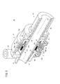
- FIG. 5 is a perspective view, partially in cross section, of the accelerator opening degree detection device 10 shown in FIG. 4 .
- Reference numeral 20 represents the axis (central axis) of the handlebar 12.
- the accelerator grip 16 comprises a hollow throttle member 24 having a flange 22, which is fitted over the hollow handlebar 12, and a grip sleeve 26 made of resin or the like, and which is fixedly mounted on the outer circumferential surface of the throttle member 24.
- the accelerator grip 16 is angularly movably (rotatably) mounted on the handlebar 12.
- the case 14 houses therein a rotor 28, which is disposed around the axis 20 of the handlebar 12 for angular movement in unison with the accelerator grip 16 as the rotor 28 turns in the direction indicated by the arrow a in FIG. 3 , and a sensor holder 32.
- the sensor holder 32 is of a hollow, substantially two-stepped cylindrical shape, and holds respective Hall ICs (magnetic sensors) 30a, 30b thereon.
- the case 14 serves as a casing that covers the rotor 28 and the sensor holder 32 in a protected manner.
- the sensor holder 32 is housed in the case 14 at a position remote from the accelerator grip 16 with the rotor 28 interposed therebetween.
- the rotor 28 has a protrusion 34 that projects toward the sensor holder 32.
- the protrusion 34 supports magnets 36a, 36b and back yokes 38a, 38b thereon.
- the back yokes 38a, 38b are disposed on an outer circumferential side relative to the magnets 36a, 36b.
- the protrusion 34, the magnets 36a, 36b, and the back yokes 38a, 38b are disposed radially outward of a hollow cylindrical member, which has a shorter radius (hereinafter referred to as an "inner projected portion 32a"), of the sensor holder 32, which is of a substantially two-stepped cylindrical shape.
- the Hall ICs 30a, 30b are disposed inside of an outer circumferential surface of the inner projected portion 32a.
- the inner projected portion 32a projects toward a position that confronts the magnets 36a, 36b, at a location located inward of the circumferential direction of the rotor 28 (the protrusion 34 of the rotor 28).
- the Hall ICs 30a, 30b are accommodated in an inner space 32b, which is defined in the inner projected portion 32a.
- the magnets 36a, 36b and the back yokes 38a, 38b are disposed outside of the Hall ICs 30a, 30b in the sensor holder 32.
- the Hall IC (first magnetic sensor) 30a detects a magnetic force of the magnet (first magnet) 36a in order to detect a turning angle of the rotor 28 (the opening degree of the accelerator grip 16)
- the Hall IC (second magnetic sensor) 30b detects a magnetic force of the magnet (second magnet) 36b in order to detect a turning angle of the rotor 28 (the opening degree of the accelerator grip 16).
- the back yokes 38a, 38b block external magnetic fields that could adversely affect the magnetic forces of the magnets 36a, 36b, thus resulting in an increase in detection accuracy of the magnetic forces of the magnets 36a, 36b by the Hall ICs 30a, 30b.
- the sensor holder 32 covers the Hall ICs 30a, 30b, so as to prevent the Hall ICs 30a, 30b from coming into contact with the outer components. A portion of the sensor holder 32 is interposed between the magnets 36a, 36b and the Hall ICs 30a, 30b, thereby preventing the magnets 36a, 36b and the Hall ICs 30a, 30b from coming into contact with each other. The sensor holder 32 also prevents the rotor 28 and the Hall ICs 30a, 30b from contacting each other in directions along the axis 20.
- the rotor 28 has a groove 40 defined therein, which houses a return spring 42 between the groove 40 and the sensor holder 32, for normally biasing the rotor 28 to move in the direction indicated by the arrow b in FIG. 3 .
- the return spring 42 has one end that engages and is supported by a hole 44 defined in the rotor 28, and another end that engages and is supported by a hole 46 defined in the sensor holder 32.
- the sensor holder 32 and the case 14 are fixed to the handlebar 12 by a bolt B.
- the bolt B also fastens the sensor holder 32 and the case 14 to each other.
- the case 14 comprises an upper case 14a and a lower case 14b.
- Detection signals which are generated by the Hall ICs 30a, 30b, are transmitted over wires 47 to a controller such as an ECU (Engine Control Unit) or the like, which is mounted on the saddle-type vehicle.
- the upper case 14a has a mounting boss 15 on which a non-illustrated side mirror is mounted.
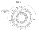
- FIG. 6 is a cross-sectional view taken along line VI-VI of FIG. 4
- FIG. 7 is a cross-sectional view similar to FIG. 6 , except that the flange 22 is omitted from illustration.
- the flange 22 of the throttle member 24 has recesses 50, 52, with a small flange sector 54 and a large flange sector 56 defined between the recesses 50, 52.
- the rotor 28 has a tooth 58 that projects toward the flange 22 and is positioned in the recess 50.
- the upper case 14a has a stopper 60 that projects radially inward (toward the flange 22) and is positioned in the recess 52. The stopper 60 limits rotational movement of the accelerator grip 16 in the direction indicated by the arrow a, and also limits rotational movement of the accelerator grip 16 in the direction indicated by the arrow b.
- the rotor 28 also has a recess 62 defined therein.
- the lower case 14b has a stopper 64 for limiting rotational movement of the rotor 28 in the direction indicated by the arrow b under the bias of the return spring 42.
- the stopper 64 When an edge of the recess 62 abuts against the stopper 64, the rotor 28 is prevented from rotating further in the direction indicated by the arrow b.
- the angular position of the rotor 28 is referred to as a turning start point. In other words, the rotor 28 is biased to return to the turning start point.
- the small flange sector 54 and the tooth 58 are turned by the return spring 42 in the direction indicated by the arrow b.
- the rotor 28 and the accelerator grip 16 are turned in the direction of the arrow b until the edge of the recess 62 of the rotor 28 abuts against the stopper 64, whereupon the rotor 28 is stopped at the turning start point.
- the accelerator grip 16 continues to turn in the direction of the arrow b until a second abutment surface 54b of the small flange sector 54 comes into abutment against an excessive return prevention stopper surface 60b of the stopper 60, at which time the rotor 28 stops turning.
- An interval between the position at which the second abutment surface 54b of the small flange sector 54 abuts against the excessive return prevention stopper surface 60b of the stopper 60 and the position at which the first abutment surface 54a abuts against the tooth 58 is referred to as a play interval of the accelerator grip 16.
- the tooth 58 serves to transmit turning movement of the accelerator grip 16 to the rotor 28.
- the stopper 60 serves as a limiting member for limiting turning movement of the accelerator grip 16 (turning movement of the accelerator grip 16 in the direction of the arrow a, as well as turning movement of the accelerator grip 16 in the direction of the arrow b).
- FIG. 8 is a cross-sectional view taken along line VIII-VIII of FIG. 4 .
- the magnets 36a, 36b are disposed in respective positions, which are diametrically opposite to each other across the axis 20 of the handlebar 12, and the magnets 36a, 36b are curved along the circumferential direction of the handlebar 12.
- the back yokes 38a, 38b are disposed respectively on outer circumferential surfaces of the magnets 36a, 36b.
- the back yokes 38a, 38b open centrally along the axis 20.
- the back yokes 38a, 38b are curved along the circumferential direction of the handlebar 12.
- the back yoke 38a has bent ends 66a, 66b, which are bent radially inward from outside of the opposite outer circumferential side edges of the magnet 36a, and the back yoke 38b has bent ends 68a, 68b, which are bent radially inward from outside of the opposite outer circumferential side edges of the magnet 36b.
- the back yokes 38a, 38b including the bent ends 66a, 66b, 68a, 68b thereof are capable of blocking an external magnetic field over a wider area, and of further eliminating an external magnetic field that adversely affects the magnetic forces of the magnets 36a, 36b, thereby resulting in a further increase in the accuracy with which the Hall ICs 30a, 30b are capable of detecting the magnetic forces of the magnets 36a, 36b.
- the back yokes 38a, 38b need not necessarily open centrally along the axis 20.
- the opening degree of the accelerator grip 16 may be detected by either one of the Hall ICs 30a, 30b, whereas the other one of the Hall ICs 30a, 30b may be used to judge whether or not the Hall IC used to detect the opening degree of the accelerator grip 16 has failed.
- the Hall IC 30a may be used to detect the opening degree of the accelerator grip 16
- the Hall IC 30b may be used to judge whether or not the Hall IC 30a has failed. If the opening degree of the accelerator grip 16, which is detected by the Hall IC 30a, and the opening degree of the accelerator grip 16, which is detected by the Hall IC 30b, differ from each other, then the controller can determine that the Hall IC 30a has failed.
- a process of assembling the accelerator opening degree detection device 10 will be described below.
- the sensor holder 32 with the Hall ICs 30a, 30b assembled therein has been fitted over the handlebar 12 from one end thereof and positioned on the handlebar 12
- the rotor 28 with the return spring 42 placed therein also is fitted over the handlebar 12 from the one end thereof and is mounted on the handlebar 12.
- one end of the return spring 42 engages and is supported in the hole 44 defined in the rotor 28, whereas the other end of the return spring 42 engages and is supported in the hole 46 defined in the sensor holder 32.
- the accelerator grip 16 is fitted over the handlebar 12 from the one end thereof.
- the accelerator grip 16 is fitted over the handlebar 12, as shown in FIG. 6 , the accelerator grip 16 is positioned such that the small flange sector 54 and the large flange sector 56 of the flange 22 sandwich the tooth 58 therebetween. Further, at this time, the accelerator grip 16 is positioned such that the tooth 58 is positioned in the recess 50 defined in the flange 22.
- the lower case 14b is fitted over the sensor holder 32, the rotor 28, and the flange 22 of the accelerator grip 16, such that the stopper 64 fits in the recess 62 defined in the rotor 28 (see FIG. 7 ).
- the upper case 14a is fitted over the sensor holder 32, the rotor 28, and the flange 22 of the accelerator grip 16, such that the stopper 60 fits in the recess 52 defined in the flange 22 (see FIG. 6 ).
- the upper case 14a, the lower case 14b, and the sensor holder 32 are fastened to the handlebar 12 by the bolt B, thereby completing assembly of the accelerator opening degree detection device 10.
- the sensor holder 32 Since the sensor holder 32 with the Hall ICs 30a, 30b assembled therein and the case 14 are separate from each other, the Hall ICs 30a, 30b can be installed on the handlebar 12 without concern over how the case 14 is placed in alignment with the handlebar 12. Therefore, the Hall ICs 30a, 30b can be installed with increased efficiency.
- the sensor holder 32 includes the inner projected portion 32a, which is positioned radially inward of the rotor 28 with the magnets 36a, 36b assembled therein, and which projects toward the position confronting the magnets 36a, 36b, while in addition, the Hall ICs 30a, 30b are disposed on the inner projected portion 32a. Consequently, the accelerator opening degree detection device 10 reduces the effect that the external magnetic field has on the Hall ICs 30a, 30b, and does not make the component (i.e., the case 14) around the accelerator grip 16 large in size.
- the Hall ICs 30a, 30b are housed in the inner space 32b defined in the inner projected portion 32a, the rotor 28 is prevented from coming into contact with the Hall ICs 30a, 30b when the rotor 28 is installed. As a result, the Hall ICs 30a, 30b and the magnets 36a, 36b can easily be installed on the handlebar 12. Unlike the background art, installation accuracy of the Hall ICs 30a, 30b with respect to the magnets 36a, 36b does not depend on the dimensional accuracy of the case 14, and the case 14 is not susceptible to dimensional errors and backlash of the handlebar 12 along the axis 20 of the handlebar 12.
- the back yokes 38a, 38b include the bent ends 66a, 66b, 68a, 68b, which are bent radially inward from outside of the opposite circumferential side edges of the magnets 36a, 36b.
- the back yokes 38a, 38b, which include the bent ends 66a, 66b, 68a, 68b, are capable of blocking external magnetic fields over a wider area, and of eliminating external magnetic fields that adversely affect the magnetic forces of the magnets 36a, 36b, thereby resulting in a further increase in accuracy with which the Hall ICs 30a, 30b detect the magnetic forces of the magnets 36a, 36b.
- the magnets 36a, 36b are disposed in respective positions, which are diametrically opposite to each other across the axis 20 of the handlebar 12.
- the Hall IC 30a detects the magnetic force of the magnet 36a
- the Hall IC 30b detects the magnetic force of the magnet 36b.
- the Hall IC 30a may be used to detect the angle of rotation of the rotor 28, whereas the Hall IC 30b may be used to judge whether the Hall IC 30a has failed or not. Therefore, whether or not the Hall IC 30a has failed can be judged with increased accuracy.
Landscapes
- Engineering & Computer Science (AREA)
- Mechanical Engineering (AREA)
- Chemical & Material Sciences (AREA)
- Combustion & Propulsion (AREA)
- General Engineering & Computer Science (AREA)
- Physics & Mathematics (AREA)
- General Physics & Mathematics (AREA)
- Steering Devices For Bicycles And Motorcycles (AREA)
- Control Of Throttle Valves Provided In The Intake System Or In The Exhaust System (AREA)
- Measurement Of Length, Angles, Or The Like Using Electric Or Magnetic Means (AREA)
Abstract
Description
- The present invention relates to an accelerator opening degree detection device including magnetic sensors for detecting the rotational position of an accelerator grip (also referred to as an "opening degree of an accelerator grip"), which is angularly movably mounted on a handlebar of a saddle-type vehicle such as a two-wheeled vehicle or the like.
- Saddle-type vehicles such as two-wheeled motor vehicles (including motorized bicycles) or the like, which are powered by an internal combustion engine, include an accelerator grip that is inserted into an end of a handlebar for engagement therewith. The accelerator grip comprises an inner tube having a flange, and a grip member in the form of a rubber member that covers the outside of the inner tube and is combined integrally therewith.
- Japanese Laid-Open Patent Publication No.
2006-112284 - When the accelerator grip is turned, the angular position of the magnet is changed, thereby causing a change in the magnetic force that is detected by the magnetic sensor.
- An output signal of the magnetic sensor, which represents an accelerator opening degree, is supplied through wires to a controller, which controls the opening of a throttle valve, for example.
- With the accelerator opening degree detection device disclosed in Japanese Laid-Open Patent Publication No.
2006-112284 - The present invention has been made in view of the aforementioned problems. It is an object of the present invention to provide an accelerator opening degree detection device, which is less susceptible to external magnetic fields, and does not make the accelerator grip large in size.
- According to the invention recited in claim 1, an accelerator opening degree detection device (10) comprises a rotor (28) mounted on a handlebar (12) around an axis (20) of the handlebar (12), the rotor (28) being capable of being turned in unison with an accelerator grip (16) as the accelerator grip (16) is turned, a magnet (36a, 36b) mounted on the rotor (28), a magnetic sensor (30a, 30b) for detecting a magnetic force of the magnet (36a, 36b), a case (14) housing the rotor (28) and the magnetic sensor (30a, 30b), the case (14) being mounted on the handlebar (12), and a sensor holder (32) housed in the case (14) at a position remote from the accelerator grip (16) with the rotor (28) interposed therebetween, the magnetic sensor (30a, 30b) being installed in the sensor holder (32), wherein the sensor holder (32) includes an inner projected portion (32a) positioned radially inward of the rotor (28) and projecting toward a position confronting the magnet (36a, 36b), and wherein the magnetic sensor (30a, 30b) is disposed in the inner projected portion (32a).
- According to the invention recited in claim 2, in the accelerator opening degree detection device (10) of claim 1, the magnetic sensor (30a, 30b) is housed in an inner space (32b) defined in the inner projected portion (32a).
- According to the invention recited in claim 3, the accelerator opening degree detection device (10) of claim 1 further comprises a back yoke (38a, 38b) mounted on the rotor (28) radially outward of the magnet (36a, 36b).
- According to the invention recited in claim 4, in the accelerator opening degree detection device (10) of claim 3, the back yoke (38a, 38b) has bent ends (66a, 66b, 68a, 68b), which are bent radially inward from outside of opposite circumferential side edges of the magnet (36a, 36b).
- According to the invention recited in claim 5, in the accelerator opening degree detection device (10) of claim 1, the magnet (36a, 36b) includes a first magnet (36a) and a second magnet (36b), the magnetic sensor (30a, 30b) includes a first magnetic sensor (30a) and a second magnetic sensor (30b), the first magnet (36a) and the second magnet (36b) are disposed in respective positions diametrically opposite to each other across the axis (20) of the handlebar (12), the first magnetic sensor (30a) detects a magnetic force of the first magnet (36a), and the second magnetic sensor (30b) detects a magnetic force of the second magnet (36b).
- According to the invention recited in claim 6, the accelerator opening degree detection device (10) of claim 1 further comprises a return spring (42) having one end thereof supported in the rotor (28) and another end thereof supported in the sensor holder (32), thereby normally biasing the rotor (28) to move to a turning start point.
- According to the invention recited in claim 1, since the sensor holder with the magnetic sensor assembled therein and the case are separate from each other, the magnetic sensor can be installed on the handlebar without concern over how the case is placed in alignment with the handlebar. Therefore, the magnetic sensor can be installed with increased efficiency. The sensor holder has the inner projected portion, which is positioned radially inward of the rotor with the magnet assembled therein and projecting toward a position confronting the magnet, and the magnetic sensor is disposed inside the inner projected portion. Consequently, the accelerator opening degree detection device reduces the effect that an external magnetic field has on the magnetic sensor. Further, the component around the accelerator grip is not increased in size.
- According to the invention recited in claim 2, since the magnetic sensor is housed in an inner space defined in the inner projected portion, the rotor is prevented from being brought into contact with the magnetic sensor when the rotor is installed. As a result, the magnetic sensor and the magnet can easily be installed on the handlebar. Unlike the background art, the accuracy with which the magnetic sensor is installed with respect to the magnet does not depend on the dimensional accuracy of the case. In addition, the case is not susceptible to dimensional errors and backlash of the handlebar along the axis of the handlebar.
- According to the invention recited in claim 3, inasmuch as the back yoke is disposed inside the rotor at a position radially outward of the magnet, the external magnetic field, which adversely affects the magnetic force of the magnet, is blocked by the back yoke. Therefore, the effect that the external magnetic field has on the magnetic force is eliminated, whereby accuracy with which the magnetic sensor detects the magnetic force of the magnet is increased.
- According to the invention recited in claim 4, the back yoke has the bent ends, which are bent radially inward from outside of opposite circumferential side edges of the magnet. The back yoke with the bent ends is capable of blocking an external magnetic field over a wider area, and of eliminating external magnetic fields that adversely affect the magnetic force of the magnet. Consequently, accuracy with which the magnetic force of the magnet is detected by the magnetic sensor can be further increased.
- According to the invention recited in claim 5, the magnetic sensors are disposed in respective symmetric positions on an axis perpendicular to the axis of the handlebar. For example, a failure of one of the magnetic sensors can be judged by the other magnetic sensor. Therefore, the accuracy with which failure of the magnetic sensor can be judged to have occurred or not is increased.
- According to the invention recited in claim 6, since the return spring is not mounted on the case, the case can be removed without being affected by the return spring. Consequently, when the case is removed to perform maintenance, the case can easily be removed, and therefore maintainability is increased.
-
-
FIG. 1 is a left-hand side elevational view of a saddle-type vehicle; -
FIG. 2 is a view of the saddle-type vehicle taken along the arrow Y ofFIG. 1 , with a front carrier thereof omitted from illustration; -
FIG. 3 is a view of an accelerator opening degree detection device according to an embodiment of the present invention, which is incorporated in the saddle-type vehicle; -
FIG. 4 is a fragmentary cross-sectional view taken along line IV-IV ofFIG. 3 ; -
FIG. 5 is a perspective view, partially in cross section, of the accelerator opening degree detection device shown inFIG. 4 ; -
FIG. 6 is a cross-sectional view taken along line VI-VI ofFIG. 4 ; -
FIG. 7 is a cross-sectional view similar toFIG. 6 except that a flange is omitted from illustration; and -
FIG. 8 is a cross-sectional view taken along line VIII-VIII ofFIG. 4 . - An accelerator opening degree detection device according to a preferred embodiment of the present invention will be described in detail below with reference to the accompanying drawings.
-
FIG. 1 is a left-hand side elevational view of a saddle-type vehicle 100 such as a two-wheeled motor vehicle. The saddle-type vehicle 100 is in the form of a scooter-type electric two-wheeled vehicle having alow floor 102. The saddle-type vehicle 100 has a rear wheel WR, which is rotatable by rotational power generated by anelectric motor 108 that is housed in aswing arm 106. The rear wheel WR has anaxle 104 that is rotatably supported on a rear end portion of theswing arm 106. - The saddle-
type vehicle 100 has a vehicle body frame, not shown, which is covered by avehicle body cover 110 made of synthetic resin that provides a vehicle body S. Thevehicle body cover 110 includes afront cover 112 covering a front side of a head pipe, not shown, of the saddle-type vehicle 100, aleg shield 116 joined to thefront cover 112 for covering a front side of the legs of a rider seated on arider seat 114, alow floor 102 joined to a lower portion of theleg shield 116 on which the feet of the rider seated on therider seat 114 can be placed, a pair of left and right floor side covers 118 hanging down from opposite sides of thelow floor 102, an undercover 120 interconnecting lower edges of the floor side covers 118, a lowerseat front cover 122 covering a front side of a lower portion of therider seat 114 and rising up from the rear end of thelow floor 102, a pair of left and right side covers 124 covering opposite sides of the lower portion of therider seat 114 and joined to opposite sides of the lowerseat front cover 122, and arear cover 126 covering an upper side of the rear wheel WR and joined to the side covers 124. - A
headlight 128 is mounted on the front end of thefront cover 112, and ataillight 130 is mounted on the rear end of therear cover 126. Afront fender 132, which is disposed below thefront cover 112, is mounted on afront fork 134 that rotatably supports a front wheel WF. Thefront fender 132 is disposed in covering relation to an upper side of the front wheel WF. Arear fender 136, which covers a rear upper side of the rear wheel WR, is joined to therear cover 126. Afender 138 also is mounted on a front portion of theswing arm 106 for covering a front upper side portion of the rear wheel WR. - A
handle 140 is joined to an upper portion of thefront fork 134. The front wheel WF can be steered by thehandle 140. Thehandle 140 has a front portion covered with ahandle cover 142. Afront carrier 144 is disposed in front of thefront cover 112. Aluggage base 146 is disposed behind therider seat 114 and above therear cover 126. Acarrier 148 is disposed above theluggage base 146. - The vehicle body frame of the saddle-
type vehicle 100 includes apivot plate 150. Aside stand 152, which holds the vehicle body S in an upright position while being tilted to the left, is angularly and movably mounted on thepivot plate 150. Theswing arm 106 has a front portion, which is swingably supported on thepivot plate 150. Amain stand 154 is angularly and movably mounted on the front portion of theswing arm 106. - As shown in
FIG. 2 ,winkers 156 are disposed as a pair respectively on left and right sides of theheadlight 128. Thewinkers 156 are formed integrally with theheadlight 128 in a unitary manner to constitute alamp unit 158. Thefront cover 112 includesfirst recesses 160 andsecond recesses 162, which are inwardly concave. Thefront carrier 144 has holes defined therein, which correspond respectively to thefirst recesses 160 and thesecond recesses 162. After the holes in thefront carrier 144 have been positioned in alignment respectively with thefirst recesses 160 and thesecond recesses 162, bolts are inserted therethrough in order to fix thefront carrier 144 and thefront cover 122 to the vehicle body frame. Theheadlight 128 has ahousing 164, which is teardrop-shaped in side elevation, and alens 166, which is circular in front elevation and is mounted on the front end of thehousing 164. Anaccelerator grip 16 is mounted on a right-hand side of thehandle 140. Theelectric motor 108 is energized so as to rotate at a speed that depends on the angle through which theaccelerator grip 16 is turned by the rider. -
FIG. 3 is a view of an accelerator openingdegree detection device 10 according to an embodiment of the present invention, which is incorporated in the saddle-type vehicle 100. The accelerator openingdegree detection device 10 includes ahandlebar 12, a case (casing) 14 mounted on thehandlebar 12, and theaccelerator grip 16, which is mounted on one end portion of thehandlebar 12.FIG. 3 also shows abrake lever 18 that is mounted on thecase 14 for facilitating understanding of the present invention, although thebrake lever 18 does not have a direct bearing on the present invention. InFIG. 4 and the following figures, thebrake lever 18 and other components, which are not required for description of the present invention, are omitted from illustration. -
FIG. 4 is a fragmentary cross-sectional view taken along line IV-IV ofFIG. 3 .FIG. 5 is a perspective view, partially in cross section, of the accelerator openingdegree detection device 10 shown inFIG. 4 .Reference numeral 20 represents the axis (central axis) of thehandlebar 12. - As shown in
FIGS. 4 and5 , theaccelerator grip 16 comprises ahollow throttle member 24 having aflange 22, which is fitted over thehollow handlebar 12, and agrip sleeve 26 made of resin or the like, and which is fixedly mounted on the outer circumferential surface of thethrottle member 24. Theaccelerator grip 16 is angularly movably (rotatably) mounted on thehandlebar 12. Thecase 14 houses therein arotor 28, which is disposed around theaxis 20 of thehandlebar 12 for angular movement in unison with theaccelerator grip 16 as therotor 28 turns in the direction indicated by the arrow a inFIG. 3 , and asensor holder 32. Thesensor holder 32 is of a hollow, substantially two-stepped cylindrical shape, and holds respective Hall ICs (magnetic sensors) 30a, 30b thereon. In other words, thecase 14 serves as a casing that covers therotor 28 and thesensor holder 32 in a protected manner. Thesensor holder 32 is housed in thecase 14 at a position remote from theaccelerator grip 16 with therotor 28 interposed therebetween. - The
rotor 28 has aprotrusion 34 that projects toward thesensor holder 32. Theprotrusion 34supports magnets back yokes magnets protrusion 34, themagnets back yokes portion 32a"), of thesensor holder 32, which is of a substantially two-stepped cylindrical shape. TheHall ICs portion 32a. The inner projectedportion 32a projects toward a position that confronts themagnets protrusion 34 of the rotor 28). TheHall ICs inner space 32b, which is defined in the inner projectedportion 32a. - In this manner, the
magnets back yokes Hall ICs sensor holder 32. The Hall IC (first magnetic sensor) 30a detects a magnetic force of the magnet (first magnet) 36a in order to detect a turning angle of the rotor 28 (the opening degree of the accelerator grip 16), whereas the Hall IC (second magnetic sensor) 30b detects a magnetic force of the magnet (second magnet) 36b in order to detect a turning angle of the rotor 28 (the opening degree of the accelerator grip 16). The back yokes 38a, 38b block external magnetic fields that could adversely affect the magnetic forces of themagnets magnets Hall ICs - The
sensor holder 32 covers theHall ICs Hall ICs sensor holder 32 is interposed between themagnets Hall ICs magnets Hall ICs sensor holder 32 also prevents therotor 28 and theHall ICs axis 20. - The
rotor 28 has agroove 40 defined therein, which houses areturn spring 42 between thegroove 40 and thesensor holder 32, for normally biasing therotor 28 to move in the direction indicated by the arrow b inFIG. 3 . Thereturn spring 42 has one end that engages and is supported by ahole 44 defined in therotor 28, and another end that engages and is supported by ahole 46 defined in thesensor holder 32. Thesensor holder 32 and thecase 14 are fixed to thehandlebar 12 by a bolt B. The bolt B also fastens thesensor holder 32 and thecase 14 to each other. Thecase 14 comprises anupper case 14a and alower case 14b. Detection signals, which are generated by theHall ICs wires 47 to a controller such as an ECU (Engine Control Unit) or the like, which is mounted on the saddle-type vehicle. Theupper case 14a has a mountingboss 15 on which a non-illustrated side mirror is mounted. -
FIG. 6 is a cross-sectional view taken along line VI-VI ofFIG. 4 , andFIG. 7 is a cross-sectional view similar toFIG. 6 , except that theflange 22 is omitted from illustration. - As shown in
FIG. 6 , theflange 22 of thethrottle member 24 hasrecesses 50, 52, with asmall flange sector 54 and alarge flange sector 56 defined between therecesses 50, 52. Therotor 28 has atooth 58 that projects toward theflange 22 and is positioned in the recess 50. Theupper case 14a has astopper 60 that projects radially inward (toward the flange 22) and is positioned in therecess 52. Thestopper 60 limits rotational movement of theaccelerator grip 16 in the direction indicated by the arrow a, and also limits rotational movement of theaccelerator grip 16 in the direction indicated by the arrow b. - As shown in
FIG. 7 , therotor 28 also has arecess 62 defined therein. Thelower case 14b has astopper 64 for limiting rotational movement of therotor 28 in the direction indicated by the arrow b under the bias of thereturn spring 42. When an edge of therecess 62 abuts against thestopper 64, therotor 28 is prevented from rotating further in the direction indicated by the arrow b. When therotor 28 abuts against thestopper 64, the angular position of therotor 28 is referred to as a turning start point. In other words, therotor 28 is biased to return to the turning start point. - When the rider turns the
accelerator grip 16 in the direction indicated by the arrow a, afirst abutment surface 54a of thesmall flange sector 54 moves in the direction of the arrow a, whereupon thefirst abutment surface 54a comes into abutment against thetooth 58. When the rider further turns theaccelerator grip 16 in the direction of the arrow a, thesmall flange sector 54 and thetooth 58 move together in the direction of the arrow a. At this time, therotor 28 turns and theHall ICs rotor 28. When the rider turns theaccelerator grip 16 to a certain angular position, a fullyopen abutment surface 56a of thelarge flange sector 56 comes into abutment against a fullyopen stopper surface 60a of thestopper 60, thereby preventing theaccelerator grip 16 from turning further in the direction of the arrow a. - Thereafter, when the rider subsequently releases the accelerator grip 16 (reverses the direction in which the
accelerator grip 16 is turned), thesmall flange sector 54 and thetooth 58 are turned by thereturn spring 42 in the direction indicated by the arrow b. Therotor 28 and theaccelerator grip 16 are turned in the direction of the arrow b until the edge of therecess 62 of therotor 28 abuts against thestopper 64, whereupon therotor 28 is stopped at the turning start point. Even if therotor 28 returns to the turning start point, theaccelerator grip 16 continues to turn in the direction of the arrow b until asecond abutment surface 54b of thesmall flange sector 54 comes into abutment against an excessive returnprevention stopper surface 60b of thestopper 60, at which time therotor 28 stops turning. An interval between the position at which thesecond abutment surface 54b of thesmall flange sector 54 abuts against the excessive returnprevention stopper surface 60b of thestopper 60 and the position at which thefirst abutment surface 54a abuts against thetooth 58 is referred to as a play interval of theaccelerator grip 16. Accordingly, thetooth 58 serves to transmit turning movement of theaccelerator grip 16 to therotor 28. Thestopper 60 serves as a limiting member for limiting turning movement of the accelerator grip 16 (turning movement of theaccelerator grip 16 in the direction of the arrow a, as well as turning movement of theaccelerator grip 16 in the direction of the arrow b). -
FIG. 8 is a cross-sectional view taken along line VIII-VIII ofFIG. 4 . Themagnets axis 20 of thehandlebar 12, and themagnets handlebar 12. The back yokes 38a, 38b are disposed respectively on outer circumferential surfaces of themagnets axis 20. The back yokes 38a, 38b are curved along the circumferential direction of thehandlebar 12. Theback yoke 38a has bentends magnet 36a, and theback yoke 38b has bentends magnet 36b. The back yokes 38a, 38b including the bent ends 66a, 66b, 68a, 68b thereof are capable of blocking an external magnetic field over a wider area, and of further eliminating an external magnetic field that adversely affects the magnetic forces of themagnets Hall ICs magnets axis 20. - The opening degree of the
accelerator grip 16 may be detected by either one of theHall ICs Hall ICs accelerator grip 16 has failed. For example, only theHall IC 30a may be used to detect the opening degree of theaccelerator grip 16, whereas theHall IC 30b may be used to judge whether or not theHall IC 30a has failed. If the opening degree of theaccelerator grip 16, which is detected by theHall IC 30a, and the opening degree of theaccelerator grip 16, which is detected by theHall IC 30b, differ from each other, then the controller can determine that theHall IC 30a has failed. - A process of assembling the accelerator opening
degree detection device 10 will be described below. After thesensor holder 32 with theHall ICs handlebar 12 from one end thereof and positioned on thehandlebar 12, therotor 28 with thereturn spring 42 placed therein also is fitted over thehandlebar 12 from the one end thereof and is mounted on thehandlebar 12. At this time, one end of thereturn spring 42 engages and is supported in thehole 44 defined in therotor 28, whereas the other end of thereturn spring 42 engages and is supported in thehole 46 defined in thesensor holder 32. - Next, the
accelerator grip 16 is fitted over thehandlebar 12 from the one end thereof. When theaccelerator grip 16 is fitted over thehandlebar 12, as shown inFIG. 6 , theaccelerator grip 16 is positioned such that thesmall flange sector 54 and thelarge flange sector 56 of theflange 22 sandwich thetooth 58 therebetween. Further, at this time, theaccelerator grip 16 is positioned such that thetooth 58 is positioned in the recess 50 defined in theflange 22. - Thereafter, the
lower case 14b is fitted over thesensor holder 32, therotor 28, and theflange 22 of theaccelerator grip 16, such that thestopper 64 fits in therecess 62 defined in the rotor 28 (seeFIG. 7 ). In addition, theupper case 14a is fitted over thesensor holder 32, therotor 28, and theflange 22 of theaccelerator grip 16, such that thestopper 60 fits in therecess 52 defined in the flange 22 (seeFIG. 6 ). Theupper case 14a, thelower case 14b, and thesensor holder 32 are fastened to thehandlebar 12 by the bolt B, thereby completing assembly of the accelerator openingdegree detection device 10. - Since the
sensor holder 32 with theHall ICs case 14 are separate from each other, theHall ICs handlebar 12 without concern over how thecase 14 is placed in alignment with thehandlebar 12. Therefore, theHall ICs sensor holder 32 includes the inner projectedportion 32a, which is positioned radially inward of therotor 28 with themagnets magnets Hall ICs portion 32a. Consequently, the accelerator openingdegree detection device 10 reduces the effect that the external magnetic field has on theHall ICs accelerator grip 16 large in size. - Since the
Hall ICs inner space 32b defined in the inner projectedportion 32a, therotor 28 is prevented from coming into contact with theHall ICs rotor 28 is installed. As a result, theHall ICs magnets handlebar 12. Unlike the background art, installation accuracy of theHall ICs magnets case 14, and thecase 14 is not susceptible to dimensional errors and backlash of thehandlebar 12 along theaxis 20 of thehandlebar 12. - In as much as the
back yokes rotor 28 at a radially outward position from themagnets magnets back yokes magnets magnets Hall ICs - The back yokes 38a, 38b include the bent ends 66a, 66b, 68a, 68b, which are bent radially inward from outside of the opposite circumferential side edges of the
magnets magnets Hall ICs magnets - The
magnets axis 20 of thehandlebar 12. TheHall IC 30a detects the magnetic force of themagnet 36a, whereas theHall IC 30b detects the magnetic force of themagnet 36b. TheHall IC 30a may be used to detect the angle of rotation of therotor 28, whereas theHall IC 30b may be used to judge whether theHall IC 30a has failed or not. Therefore, whether or not theHall IC 30a has failed can be judged with increased accuracy. - In so far as the
return spring 42 is not mounted on thecase 14, thereturn spring 42 is not dislodged even at times that thecase 14 is removed for maintenance. Consequently, thecase 14 can easily be removed for improving ease of maintenance. - The present invention has been described above with respect to a preferred embodiment thereof. However, the technical scope of the present invention is not limited to the embodiment illustrated above. It will be obvious to those skilled in the art that various improvements or modifications can be made with respect to the aforementioned embodiment. It is apparent from the scope of the claims that configurations, which are based on such improvements or modifications, fall within the technical scope of the present invention. The parenthetical reference characters which are referred to in the patent claims correspond with the reference characters shown in the accompanying drawings for thereby facilitating understanding of the present invention. However, the present invention should not be construed as being limited to the elements denoted by such reference characters.
Claims (6)
- An accelerator opening degree detection device (10) comprising:a rotor (28) mounted on a handlebar (12) around an axis (20) of the handlebar (12), the rotor (28) being capable of being turned in unison with an accelerator grip (16) as the accelerator grip (16) is turned;a magnet (36a, 36b) mounted on the rotor (28);a magnetic sensor (30a, 30b) for detecting a magnetic force of the magnet (36a, 36b);a case (14) housing the rotor (28) and the magnetic sensor (30a, 30b), the case (14) being mounted on the handlebar (12); anda sensor holder (32) housed in the case (14) at a position remote from the accelerator grip (16) with the rotor (28) interposed therebetween, the magnetic sensor (30a, 30b) being installed in the sensor holder (32);wherein the sensor holder (32) includes an inner projected portion (32a) positioned radially inward of the rotor (28), and projecting toward a position confronting the magnet (36a, 36b); andwherein the magnetic sensor (30a, 30b) is disposed in the inner projected portion (32a).
- The accelerator opening degree detection device (10) according to claim 1, wherein the magnetic sensor (30a, 30b) is housed in an inner space (32b) defined in the inner projected portion (32a).
- The accelerator opening degree detection device (10) according to claim 1, further comprising:a back yoke (38a, 38b) mounted on the rotor (28) radially outward of the magnet (36a, 36b).
- The accelerator opening degree detection device (10) according to claim 3, wherein the back yoke (38a, 38b) has bent ends (66a, 66b, 68a, 68b), which are bent radially inward from outside of opposite circumferential side edges of the magnet (36a, 36b).
- The accelerator opening degree detection device (10) according to claim 1, wherein the magnet (36a, 36b) includes a first magnet (36a) and a second magnet (36b);
the magnetic sensor (30a, 30b) includes a first magnetic sensor (30a) and a second magnetic sensor (30b);
the first magnet (36a) and the second magnet (36b) are disposed in respective positions diametrically opposite to each other across the axis (20) of the handlebar (12);
the first magnetic sensor (30a) detects a magnetic force of the first magnet (36a); and
the second magnetic sensor (30b) detects a magnetic force of the second magnet (36b). - The accelerator opening degree detection device (10) according to claim 1, further comprising:a return spring (42) having one end thereof supported in the rotor (28) and another end thereof supported in the sensor holder (32), thereby normally biasing the rotor (28) to move to a turning start point.
Applications Claiming Priority (1)
| Application Number | Priority Date | Filing Date | Title |
|---|---|---|---|
| PCT/JP2011/065050 WO2013001640A1 (en) | 2011-06-30 | 2011-06-30 | Accelerator opening degree detection device |
Publications (3)
| Publication Number | Publication Date |
|---|---|
| EP2716891A1 true EP2716891A1 (en) | 2014-04-09 |
| EP2716891A4 EP2716891A4 (en) | 2014-12-03 |
| EP2716891B1 EP2716891B1 (en) | 2016-01-13 |
Family
ID=47423581
Family Applications (1)
| Application Number | Title | Priority Date | Filing Date |
|---|---|---|---|
| EP11868836.5A Not-in-force EP2716891B1 (en) | 2011-06-30 | 2011-06-30 | Accelerator opening degree detection device |
Country Status (8)
| Country | Link |
|---|---|
| US (1) | US9752862B2 (en) |
| EP (1) | EP2716891B1 (en) |
| JP (1) | JP5727009B2 (en) |
| CN (1) | CN103620192B (en) |
| BR (1) | BR112013033564A2 (en) |
| ES (1) | ES2567575T3 (en) |
| TW (1) | TWI448615B (en) |
| WO (1) | WO2013001640A1 (en) |
Cited By (3)
| Publication number | Priority date | Publication date | Assignee | Title |
|---|---|---|---|---|
| WO2019058044A1 (en) | 2017-09-25 | 2019-03-28 | Moving Magnet Technologies | Detection module for a rotary handle of a motorized vehicle |
| WO2022238390A1 (en) * | 2021-05-12 | 2022-11-17 | Robert Bosch Gmbh | Method for detecting limited movability of a throttle grip for a motorcycle, control unit and motorcycle system |
| EP4151512A1 (en) * | 2021-09-17 | 2023-03-22 | Asahi Denso Co., Ltd. | Throttle grip device |
Families Citing this family (8)
| Publication number | Priority date | Publication date | Assignee | Title |
|---|---|---|---|---|
| JP6289399B2 (en) * | 2015-02-23 | 2018-03-07 | 本田技研工業株式会社 | Position detection device |
| US11408910B2 (en) | 2017-03-24 | 2022-08-09 | Honda Motor Co., Ltd. | Accelerator position detection device with improved abnormal detection |
| TWI628431B (en) * | 2017-04-12 | 2018-07-01 | 國立中山大學 | Automatic detection device for iron particle concentration in oil |
| JP6982536B2 (en) * | 2018-03-30 | 2021-12-17 | 日立Astemo株式会社 | Grip opening detection device |
| JP7158189B2 (en) * | 2018-07-11 | 2022-10-21 | 東洋電装株式会社 | throttle grip device |
| CN113513417B (en) * | 2020-04-10 | 2023-11-24 | 本田技研工业株式会社 | throttle device |
| JP7733506B2 (en) * | 2021-08-24 | 2025-09-03 | 東洋電装株式会社 | Accelerator position sensor unit and throttle grip device |
| US20230294789A1 (en) * | 2022-03-15 | 2023-09-21 | Super73, Inc. | Electric motorbike handlebar grip arrangement |
Family Cites Families (28)
| Publication number | Priority date | Publication date | Assignee | Title |
|---|---|---|---|---|
| JP2002039712A (en) * | 2000-07-27 | 2002-02-06 | Mikuni Corp | Connection structure of non-contact type rotary sensor and rotating shaft |
| US6541959B2 (en) * | 2001-02-27 | 2003-04-01 | S & S Cycle, Inc. | Angular position sensing system with magnet and rotor arrangement |
| JP2002256904A (en) | 2001-02-28 | 2002-09-11 | Mikuni Corp | Accelerator operation device |
| JP2002303535A (en) * | 2001-04-03 | 2002-10-18 | Mikuni Corp | Magnetic position sensor |
| JP4109852B2 (en) * | 2001-10-19 | 2008-07-02 | ヤマハ発動機株式会社 | Throttle opening detection device for electric motorcycle |
| JP2003252273A (en) * | 2002-02-26 | 2003-09-10 | Yamaha Motor Co Ltd | Throttle opening detector |
| TW590917B (en) | 2002-08-12 | 2004-06-11 | Yamaha Motor Co Ltd | Electric throttle |
| JP4891070B2 (en) * | 2004-05-28 | 2012-03-07 | 株式会社ミクニ | Accelerator operating device |
| JP4911889B2 (en) | 2004-10-14 | 2012-04-04 | ヤマハ発動機株式会社 | Relative position detection device and saddle riding type vehicle |
| JP4401926B2 (en) | 2004-10-14 | 2010-01-20 | ヤマハ発動機株式会社 | Relative position detection control device and saddle riding type vehicle |
| JP4544135B2 (en) * | 2005-11-10 | 2010-09-15 | 株式会社デンソー | Rotation angle detection unit |
| JP4941807B2 (en) * | 2006-01-13 | 2012-05-30 | 日本精機株式会社 | Angle detector |
| FR2898189B1 (en) * | 2006-03-02 | 2008-10-17 | Moving Magnet Tech | POSITION SENSOR WITH VARIABLE MAGNET DIRECTION AND METHOD OF MAKING SAME |
| JP4294036B2 (en) * | 2006-03-29 | 2009-07-08 | 三菱電機株式会社 | Rotation angle detector |
| ITTO20060526A1 (en) * | 2006-07-19 | 2008-01-20 | Bitron Spa | KNOB CONTROL DEVICE, PARTICULARLY FOR MOTOR VEHICLES. |
| TWM305161U (en) | 2006-08-08 | 2007-01-21 | Chao Long Technology Corp | Optical detecting apparatus for throttle |
| JP4777944B2 (en) * | 2007-07-03 | 2011-09-21 | 本田技研工業株式会社 | Vehicle throttle device |
| JP2009058329A (en) * | 2007-08-31 | 2009-03-19 | Victor Co Of Japan Ltd | Magnetization yoke, magnet magnetization method, magnet, position detection device, and deflection correction device |
| ITMI20080632A1 (en) * | 2008-04-10 | 2009-10-11 | Domino Spa | ELECTRONIC GAS CONTROL DEVICE PERFECTED FOR MOTORCYCLES, MOTORCYCLES, MOTORBIKES AND SIMILAR VEHICLES |
| JP2010151731A (en) * | 2008-12-26 | 2010-07-08 | Nippon Seiki Co Ltd | Position detector |
| JP5436459B2 (en) * | 2009-02-16 | 2014-03-05 | 株式会社ミクニ | Accelerator device |
| JP5442323B2 (en) * | 2009-06-05 | 2014-03-12 | 朝日電装株式会社 | Throttle grip device |
| JP5448148B2 (en) | 2009-06-05 | 2014-03-19 | 朝日電装株式会社 | Throttle grip device |
| TWM374050U (en) | 2009-06-26 | 2010-02-11 | Shao-Te Kuo | Electromagnetic induction contactless angle sensor |
| US20120266717A1 (en) * | 2009-11-24 | 2012-10-25 | Yamaha Hatsudoki Kabushiki Kaisha | Saddle type vehicle |
| TWM392136U (en) | 2010-06-25 | 2010-11-11 | Tong Yah Ind Co Ltd | Acceleration handgrip for electric vehicle |
| JP2012047624A (en) * | 2010-08-27 | 2012-03-08 | Nippon Seiki Co Ltd | Position detection device |
| JP5672509B2 (en) * | 2012-11-28 | 2015-02-18 | 株式会社デンソー | Accelerator device |
-
2011
- 2011-06-30 EP EP11868836.5A patent/EP2716891B1/en not_active Not-in-force
- 2011-06-30 CN CN201180071963.5A patent/CN103620192B/en not_active Expired - Fee Related
- 2011-06-30 ES ES11868836.5T patent/ES2567575T3/en active Active
- 2011-06-30 WO PCT/JP2011/065050 patent/WO2013001640A1/en not_active Ceased
- 2011-06-30 BR BR112013033564A patent/BR112013033564A2/en active Search and Examination
- 2011-06-30 US US14/125,961 patent/US9752862B2/en not_active Expired - Fee Related
- 2011-06-30 JP JP2013522596A patent/JP5727009B2/en not_active Expired - Fee Related
-
2012
- 2012-06-26 TW TW101122807A patent/TWI448615B/en not_active IP Right Cessation
Cited By (4)
| Publication number | Priority date | Publication date | Assignee | Title |
|---|---|---|---|---|
| WO2019058044A1 (en) | 2017-09-25 | 2019-03-28 | Moving Magnet Technologies | Detection module for a rotary handle of a motorized vehicle |
| WO2022238390A1 (en) * | 2021-05-12 | 2022-11-17 | Robert Bosch Gmbh | Method for detecting limited movability of a throttle grip for a motorcycle, control unit and motorcycle system |
| EP4151512A1 (en) * | 2021-09-17 | 2023-03-22 | Asahi Denso Co., Ltd. | Throttle grip device |
| US11873056B2 (en) | 2021-09-17 | 2024-01-16 | Asahi Denso Co., Ltd. | Throttle grip device |
Also Published As
| Publication number | Publication date |
|---|---|
| TW201315893A (en) | 2013-04-16 |
| US9752862B2 (en) | 2017-09-05 |
| CN103620192A (en) | 2014-03-05 |
| CN103620192B (en) | 2016-06-08 |
| TWI448615B (en) | 2014-08-11 |
| WO2013001640A1 (en) | 2013-01-03 |
| JPWO2013001640A1 (en) | 2015-02-23 |
| JP5727009B2 (en) | 2015-06-03 |
| US20140103916A1 (en) | 2014-04-17 |
| EP2716891B1 (en) | 2016-01-13 |
| ES2567575T3 (en) | 2016-04-25 |
| BR112013033564A2 (en) | 2017-02-07 |
| EP2716891A4 (en) | 2014-12-03 |
Similar Documents
| Publication | Publication Date | Title |
|---|---|---|
| EP2716891B1 (en) | Accelerator opening degree detection device | |
| CN104144848B (en) | Electric bicycle | |
| US8666581B2 (en) | Bicycle motor control apparatus | |
| EP2011728B1 (en) | Vehicle having a throttle device | |
| US8051939B2 (en) | Throttle control apparatus for a vehicle and vehicle incorporating same | |
| JP4648816B2 (en) | Vehicle lamp device | |
| US7347071B2 (en) | Vehicle provided with key cylinder device equipped with handle lock mechanism | |
| TWI828335B (en) | Speed sensing systems for a bicycle | |
| JP4777944B2 (en) | Vehicle throttle device | |
| JP7432873B2 (en) | Power transmission unit for electric bicycle and electric bicycle | |
| JP2021062689A (en) | Drive unit and power-assisted bicycle | |
| CN103963902B (en) | Bicycle operating device | |
| JP5809777B2 (en) | Vehicle speed sensor for vehicle and electric bicycle provided with vehicle speed sensor | |
| JP5606601B2 (en) | Vehicle speed sensor for vehicle and electric bicycle provided with vehicle speed sensor | |
| JP6464130B2 (en) | Pulsar ring mounting structure | |
| US10113642B2 (en) | Rotation detecting device | |
| KR101168855B1 (en) | Torque sensor for Power Assist System | |
| TWI403429B (en) | Vehicle speed sensor configuration in vehicle | |
| JP2009220667A (en) | Electric bicycle | |
| JP2013112259A (en) | Vehicle meter device | |
| EP2511165A1 (en) | Torque sensing device on rear axle and electric bicycle | |
| JP2014032032A (en) | Saddle type vehicle with engine | |
| CN113513417B (en) | throttle device | |
| JP2011218947A (en) | Steering lock mechanism | |
| JP2012116423A (en) | Throttle apparatus |
Legal Events
| Date | Code | Title | Description |
|---|---|---|---|
| PUAI | Public reference made under article 153(3) epc to a published international application that has entered the european phase |
Free format text: ORIGINAL CODE: 0009012 |
|
| 17P | Request for examination filed |
Effective date: 20131230 |
|
| AK | Designated contracting states |
Kind code of ref document: A1 Designated state(s): AL AT BE BG CH CY CZ DE DK EE ES FI FR GB GR HR HU IE IS IT LI LT LU LV MC MK MT NL NO PL PT RO RS SE SI SK SM TR |
|
| DAX | Request for extension of the european patent (deleted) | ||
| A4 | Supplementary search report drawn up and despatched |
Effective date: 20141105 |
|
| RIC1 | Information provided on ipc code assigned before grant |
Ipc: F02D 11/10 20060101AFI20141030BHEP Ipc: B62K 23/04 20060101ALI20141030BHEP |
|
| REG | Reference to a national code |
Ref country code: DE Ref legal event code: R079 Ref document number: 602011022739 Country of ref document: DE Free format text: PREVIOUS MAIN CLASS: F02D0011100000 Ipc: F02D0011020000 |
|
| GRAP | Despatch of communication of intention to grant a patent |
Free format text: ORIGINAL CODE: EPIDOSNIGR1 |
|
| RIC1 | Information provided on ipc code assigned before grant |
Ipc: B62K 23/04 20060101ALI20150629BHEP Ipc: F02D 11/02 20060101AFI20150629BHEP Ipc: F02D 11/10 20060101ALI20150629BHEP |
|
| INTG | Intention to grant announced |
Effective date: 20150717 |
|
| GRAS | Grant fee paid |
Free format text: ORIGINAL CODE: EPIDOSNIGR3 |
|
| GRAA | (expected) grant |
Free format text: ORIGINAL CODE: 0009210 |
|
| AK | Designated contracting states |
Kind code of ref document: B1 Designated state(s): AL AT BE BG CH CY CZ DE DK EE ES FI FR GB GR HR HU IE IS IT LI LT LU LV MC MK MT NL NO PL PT RO RS SE SI SK SM TR |
|
| REG | Reference to a national code |
Ref country code: GB Ref legal event code: FG4D |
|
| REG | Reference to a national code |
Ref country code: CH Ref legal event code: EP |
|
| REG | Reference to a national code |
Ref country code: IE Ref legal event code: FG4D |
|
| REG | Reference to a national code |
Ref country code: AT Ref legal event code: REF Ref document number: 770687 Country of ref document: AT Kind code of ref document: T Effective date: 20160215 |
|
| REG | Reference to a national code |
Ref country code: DE Ref legal event code: R096 Ref document number: 602011022739 Country of ref document: DE |
|
| REG | Reference to a national code |
Ref country code: ES Ref legal event code: FG2A Ref document number: 2567575 Country of ref document: ES Kind code of ref document: T3 Effective date: 20160425 |
|
| REG | Reference to a national code |
Ref country code: LT Ref legal event code: MG4D |
|
| REG | Reference to a national code |
Ref country code: NL Ref legal event code: MP Effective date: 20160113 |
|
| REG | Reference to a national code |
Ref country code: AT Ref legal event code: MK05 Ref document number: 770687 Country of ref document: AT Kind code of ref document: T Effective date: 20160113 |
|
| REG | Reference to a national code |
Ref country code: FR Ref legal event code: PLFP Year of fee payment: 6 |
|
| PG25 | Lapsed in a contracting state [announced via postgrant information from national office to epo] |
Ref country code: NL Free format text: LAPSE BECAUSE OF FAILURE TO SUBMIT A TRANSLATION OF THE DESCRIPTION OR TO PAY THE FEE WITHIN THE PRESCRIBED TIME-LIMIT Effective date: 20160113 |
|
| PG25 | Lapsed in a contracting state [announced via postgrant information from national office to epo] |
Ref country code: HR Free format text: LAPSE BECAUSE OF FAILURE TO SUBMIT A TRANSLATION OF THE DESCRIPTION OR TO PAY THE FEE WITHIN THE PRESCRIBED TIME-LIMIT Effective date: 20160113 Ref country code: FI Free format text: LAPSE BECAUSE OF FAILURE TO SUBMIT A TRANSLATION OF THE DESCRIPTION OR TO PAY THE FEE WITHIN THE PRESCRIBED TIME-LIMIT Effective date: 20160113 Ref country code: GR Free format text: LAPSE BECAUSE OF FAILURE TO SUBMIT A TRANSLATION OF THE DESCRIPTION OR TO PAY THE FEE WITHIN THE PRESCRIBED TIME-LIMIT Effective date: 20160414 Ref country code: NO Free format text: LAPSE BECAUSE OF FAILURE TO SUBMIT A TRANSLATION OF THE DESCRIPTION OR TO PAY THE FEE WITHIN THE PRESCRIBED TIME-LIMIT Effective date: 20160413 |
|
| PG25 | Lapsed in a contracting state [announced via postgrant information from national office to epo] |
Ref country code: SE Free format text: LAPSE BECAUSE OF FAILURE TO SUBMIT A TRANSLATION OF THE DESCRIPTION OR TO PAY THE FEE WITHIN THE PRESCRIBED TIME-LIMIT Effective date: 20160113 Ref country code: PT Free format text: LAPSE BECAUSE OF FAILURE TO SUBMIT A TRANSLATION OF THE DESCRIPTION OR TO PAY THE FEE WITHIN THE PRESCRIBED TIME-LIMIT Effective date: 20160513 Ref country code: AT Free format text: LAPSE BECAUSE OF FAILURE TO SUBMIT A TRANSLATION OF THE DESCRIPTION OR TO PAY THE FEE WITHIN THE PRESCRIBED TIME-LIMIT Effective date: 20160113 Ref country code: IS Free format text: LAPSE BECAUSE OF FAILURE TO SUBMIT A TRANSLATION OF THE DESCRIPTION OR TO PAY THE FEE WITHIN THE PRESCRIBED TIME-LIMIT Effective date: 20160513 Ref country code: RS Free format text: LAPSE BECAUSE OF FAILURE TO SUBMIT A TRANSLATION OF THE DESCRIPTION OR TO PAY THE FEE WITHIN THE PRESCRIBED TIME-LIMIT Effective date: 20160113 Ref country code: LT Free format text: LAPSE BECAUSE OF FAILURE TO SUBMIT A TRANSLATION OF THE DESCRIPTION OR TO PAY THE FEE WITHIN THE PRESCRIBED TIME-LIMIT Effective date: 20160113 Ref country code: LV Free format text: LAPSE BECAUSE OF FAILURE TO SUBMIT A TRANSLATION OF THE DESCRIPTION OR TO PAY THE FEE WITHIN THE PRESCRIBED TIME-LIMIT Effective date: 20160113 Ref country code: PL Free format text: LAPSE BECAUSE OF FAILURE TO SUBMIT A TRANSLATION OF THE DESCRIPTION OR TO PAY THE FEE WITHIN THE PRESCRIBED TIME-LIMIT Effective date: 20160113 |
|
| REG | Reference to a national code |
Ref country code: DE Ref legal event code: R097 Ref document number: 602011022739 Country of ref document: DE |
|
| PG25 | Lapsed in a contracting state [announced via postgrant information from national office to epo] |
Ref country code: DK Free format text: LAPSE BECAUSE OF FAILURE TO SUBMIT A TRANSLATION OF THE DESCRIPTION OR TO PAY THE FEE WITHIN THE PRESCRIBED TIME-LIMIT Effective date: 20160113 Ref country code: EE Free format text: LAPSE BECAUSE OF FAILURE TO SUBMIT A TRANSLATION OF THE DESCRIPTION OR TO PAY THE FEE WITHIN THE PRESCRIBED TIME-LIMIT Effective date: 20160113 |
|
| PLBE | No opposition filed within time limit |
Free format text: ORIGINAL CODE: 0009261 |
|
| STAA | Information on the status of an ep patent application or granted ep patent |
Free format text: STATUS: NO OPPOSITION FILED WITHIN TIME LIMIT |
|
| PG25 | Lapsed in a contracting state [announced via postgrant information from national office to epo] |
Ref country code: RO Free format text: LAPSE BECAUSE OF FAILURE TO SUBMIT A TRANSLATION OF THE DESCRIPTION OR TO PAY THE FEE WITHIN THE PRESCRIBED TIME-LIMIT Effective date: 20160113 Ref country code: SM Free format text: LAPSE BECAUSE OF FAILURE TO SUBMIT A TRANSLATION OF THE DESCRIPTION OR TO PAY THE FEE WITHIN THE PRESCRIBED TIME-LIMIT Effective date: 20160113 Ref country code: CZ Free format text: LAPSE BECAUSE OF FAILURE TO SUBMIT A TRANSLATION OF THE DESCRIPTION OR TO PAY THE FEE WITHIN THE PRESCRIBED TIME-LIMIT Effective date: 20160113 Ref country code: SK Free format text: LAPSE BECAUSE OF FAILURE TO SUBMIT A TRANSLATION OF THE DESCRIPTION OR TO PAY THE FEE WITHIN THE PRESCRIBED TIME-LIMIT Effective date: 20160113 |
|
| 26N | No opposition filed |
Effective date: 20161014 |
|
| PG25 | Lapsed in a contracting state [announced via postgrant information from national office to epo] |
Ref country code: BE Free format text: LAPSE BECAUSE OF FAILURE TO SUBMIT A TRANSLATION OF THE DESCRIPTION OR TO PAY THE FEE WITHIN THE PRESCRIBED TIME-LIMIT Effective date: 20160113 |
|
| PG25 | Lapsed in a contracting state [announced via postgrant information from national office to epo] |
Ref country code: MC Free format text: LAPSE BECAUSE OF FAILURE TO SUBMIT A TRANSLATION OF THE DESCRIPTION OR TO PAY THE FEE WITHIN THE PRESCRIBED TIME-LIMIT Effective date: 20160113 |
|
| REG | Reference to a national code |
Ref country code: CH Ref legal event code: PL |
|
| PG25 | Lapsed in a contracting state [announced via postgrant information from national office to epo] |
Ref country code: BG Free format text: LAPSE BECAUSE OF FAILURE TO SUBMIT A TRANSLATION OF THE DESCRIPTION OR TO PAY THE FEE WITHIN THE PRESCRIBED TIME-LIMIT Effective date: 20160413 Ref country code: SI Free format text: LAPSE BECAUSE OF FAILURE TO SUBMIT A TRANSLATION OF THE DESCRIPTION OR TO PAY THE FEE WITHIN THE PRESCRIBED TIME-LIMIT Effective date: 20160113 |
|
| GBPC | Gb: european patent ceased through non-payment of renewal fee |
Effective date: 20160630 |
|
| REG | Reference to a national code |
Ref country code: IE Ref legal event code: MM4A |
|
| PG25 | Lapsed in a contracting state [announced via postgrant information from national office to epo] |
Ref country code: LI Free format text: LAPSE BECAUSE OF NON-PAYMENT OF DUE FEES Effective date: 20160630 Ref country code: CH Free format text: LAPSE BECAUSE OF NON-PAYMENT OF DUE FEES Effective date: 20160630 |
|
| REG | Reference to a national code |
Ref country code: FR Ref legal event code: PLFP Year of fee payment: 7 |
|
| PG25 | Lapsed in a contracting state [announced via postgrant information from national office to epo] |
Ref country code: IE Free format text: LAPSE BECAUSE OF NON-PAYMENT OF DUE FEES Effective date: 20160630 Ref country code: GB Free format text: LAPSE BECAUSE OF NON-PAYMENT OF DUE FEES Effective date: 20160630 |
|
| REG | Reference to a national code |
Ref country code: FR Ref legal event code: PLFP Year of fee payment: 8 |
|
| PG25 | Lapsed in a contracting state [announced via postgrant information from national office to epo] |
Ref country code: CY Free format text: LAPSE BECAUSE OF FAILURE TO SUBMIT A TRANSLATION OF THE DESCRIPTION OR TO PAY THE FEE WITHIN THE PRESCRIBED TIME-LIMIT Effective date: 20160113 Ref country code: HU Free format text: LAPSE BECAUSE OF FAILURE TO SUBMIT A TRANSLATION OF THE DESCRIPTION OR TO PAY THE FEE WITHIN THE PRESCRIBED TIME-LIMIT; INVALID AB INITIO Effective date: 20110630 |
|
| PG25 | Lapsed in a contracting state [announced via postgrant information from national office to epo] |
Ref country code: MT Free format text: LAPSE BECAUSE OF NON-PAYMENT OF DUE FEES Effective date: 20160630 Ref country code: MK Free format text: LAPSE BECAUSE OF FAILURE TO SUBMIT A TRANSLATION OF THE DESCRIPTION OR TO PAY THE FEE WITHIN THE PRESCRIBED TIME-LIMIT Effective date: 20160113 Ref country code: LU Free format text: LAPSE BECAUSE OF NON-PAYMENT OF DUE FEES Effective date: 20160630 Ref country code: TR Free format text: LAPSE BECAUSE OF FAILURE TO SUBMIT A TRANSLATION OF THE DESCRIPTION OR TO PAY THE FEE WITHIN THE PRESCRIBED TIME-LIMIT Effective date: 20160113 |
|
| PG25 | Lapsed in a contracting state [announced via postgrant information from national office to epo] |
Ref country code: AL Free format text: LAPSE BECAUSE OF FAILURE TO SUBMIT A TRANSLATION OF THE DESCRIPTION OR TO PAY THE FEE WITHIN THE PRESCRIBED TIME-LIMIT Effective date: 20160113 |
|
| PGFP | Annual fee paid to national office [announced via postgrant information from national office to epo] |
Ref country code: FR Payment date: 20190510 Year of fee payment: 9 |
|
| PGFP | Annual fee paid to national office [announced via postgrant information from national office to epo] |
Ref country code: ES Payment date: 20190701 Year of fee payment: 9 |
|
| REG | Reference to a national code |
Ref country code: DE Ref legal event code: R084 Ref document number: 602011022739 Country of ref document: DE |
|
| PGFP | Annual fee paid to national office [announced via postgrant information from national office to epo] |
Ref country code: IT Payment date: 20200512 Year of fee payment: 10 |
|
| PG25 | Lapsed in a contracting state [announced via postgrant information from national office to epo] |
Ref country code: FR Free format text: LAPSE BECAUSE OF NON-PAYMENT OF DUE FEES Effective date: 20200630 |
|
| PGFP | Annual fee paid to national office [announced via postgrant information from national office to epo] |
Ref country code: DE Payment date: 20210602 Year of fee payment: 11 |
|
| REG | Reference to a national code |
Ref country code: ES Ref legal event code: FD2A Effective date: 20211126 |
|
| PG25 | Lapsed in a contracting state [announced via postgrant information from national office to epo] |
Ref country code: ES Free format text: LAPSE BECAUSE OF NON-PAYMENT OF DUE FEES Effective date: 20200701 |
|
| PG25 | Lapsed in a contracting state [announced via postgrant information from national office to epo] |
Ref country code: IT Free format text: LAPSE BECAUSE OF NON-PAYMENT OF DUE FEES Effective date: 20210630 |
|
| REG | Reference to a national code |
Ref country code: DE Ref legal event code: R119 Ref document number: 602011022739 Country of ref document: DE |
|
| PG25 | Lapsed in a contracting state [announced via postgrant information from national office to epo] |
Ref country code: DE Free format text: LAPSE BECAUSE OF NON-PAYMENT OF DUE FEES Effective date: 20230103 |