EP2716890A2 - Gas turbine engine with a multiple fuel delivery system - Google Patents
Gas turbine engine with a multiple fuel delivery system Download PDFInfo
- Publication number
- EP2716890A2 EP2716890A2 EP20130187110 EP13187110A EP2716890A2 EP 2716890 A2 EP2716890 A2 EP 2716890A2 EP 20130187110 EP20130187110 EP 20130187110 EP 13187110 A EP13187110 A EP 13187110A EP 2716890 A2 EP2716890 A2 EP 2716890A2
- Authority
- EP
- European Patent Office
- Prior art keywords
- fuel
- delivery system
- pump
- mixing chamber
- flow
- Prior art date
- Legal status (The legal status is an assumption and is not a legal conclusion. Google has not performed a legal analysis and makes no representation as to the accuracy of the status listed.)
- Granted
Links
- 239000000446 fuel Substances 0.000 title claims abstract description 186
- 238000002156 mixing Methods 0.000 claims abstract description 56
- 239000002828 fuel tank Substances 0.000 claims abstract description 35
- 238000004891 communication Methods 0.000 claims abstract description 25
- 239000002283 diesel fuel Substances 0.000 claims description 33
- 238000005461 lubrication Methods 0.000 claims description 19
- 238000005457 optimization Methods 0.000 claims description 16
- 239000003225 biodiesel Substances 0.000 claims description 12
- 239000003795 chemical substances by application Substances 0.000 claims description 10
- 238000002485 combustion reaction Methods 0.000 claims description 10
- 238000000034 method Methods 0.000 claims description 7
- 238000005086 pumping Methods 0.000 claims description 4
- 238000001816 cooling Methods 0.000 claims description 3
- 239000007789 gas Substances 0.000 description 26
- 239000000203 mixture Substances 0.000 description 21
- VNWKTOKETHGBQD-UHFFFAOYSA-N methane Chemical compound C VNWKTOKETHGBQD-UHFFFAOYSA-N 0.000 description 6
- 238000013461 design Methods 0.000 description 5
- 238000002955 isolation Methods 0.000 description 5
- 239000002551 biofuel Substances 0.000 description 3
- 239000000567 combustion gas Substances 0.000 description 3
- 239000003345 natural gas Substances 0.000 description 3
- 238000011144 upstream manufacturing Methods 0.000 description 2
- 238000004140 cleaning Methods 0.000 description 1
- 238000005260 corrosion Methods 0.000 description 1
- 230000007797 corrosion Effects 0.000 description 1
- 238000009826 distribution Methods 0.000 description 1
- 230000009977 dual effect Effects 0.000 description 1
- 239000000295 fuel oil Substances 0.000 description 1
- 239000010763 heavy fuel oil Substances 0.000 description 1
- 239000008240 homogeneous mixture Substances 0.000 description 1
- 230000001050 lubricating effect Effects 0.000 description 1
- 239000003208 petroleum Substances 0.000 description 1
- 238000010248 power generation Methods 0.000 description 1
- 238000002360 preparation method Methods 0.000 description 1
- 238000010926 purge Methods 0.000 description 1
- 238000012552 review Methods 0.000 description 1
- 238000012546 transfer Methods 0.000 description 1
Images


Classifications
-
- F—MECHANICAL ENGINEERING; LIGHTING; HEATING; WEAPONS; BLASTING
- F02—COMBUSTION ENGINES; HOT-GAS OR COMBUSTION-PRODUCT ENGINE PLANTS
- F02C—GAS-TURBINE PLANTS; AIR INTAKES FOR JET-PROPULSION PLANTS; CONTROLLING FUEL SUPPLY IN AIR-BREATHING JET-PROPULSION PLANTS
- F02C9/00—Controlling gas-turbine plants; Controlling fuel supply in air- breathing jet-propulsion plants
- F02C9/26—Control of fuel supply
- F02C9/40—Control of fuel supply specially adapted to the use of a special fuel or a plurality of fuels
-
- F—MECHANICAL ENGINEERING; LIGHTING; HEATING; WEAPONS; BLASTING
- F02—COMBUSTION ENGINES; HOT-GAS OR COMBUSTION-PRODUCT ENGINE PLANTS
- F02C—GAS-TURBINE PLANTS; AIR INTAKES FOR JET-PROPULSION PLANTS; CONTROLLING FUEL SUPPLY IN AIR-BREATHING JET-PROPULSION PLANTS
- F02C3/00—Gas-turbine plants characterised by the use of combustion products as the working fluid
- F02C3/20—Gas-turbine plants characterised by the use of combustion products as the working fluid using a special fuel, oxidant, or dilution fluid to generate the combustion products
- F02C3/24—Gas-turbine plants characterised by the use of combustion products as the working fluid using a special fuel, oxidant, or dilution fluid to generate the combustion products the fuel or oxidant being liquid at standard temperature and pressure
-
- F—MECHANICAL ENGINEERING; LIGHTING; HEATING; WEAPONS; BLASTING
- F02—COMBUSTION ENGINES; HOT-GAS OR COMBUSTION-PRODUCT ENGINE PLANTS
- F02C—GAS-TURBINE PLANTS; AIR INTAKES FOR JET-PROPULSION PLANTS; CONTROLLING FUEL SUPPLY IN AIR-BREATHING JET-PROPULSION PLANTS
- F02C7/00—Features, components parts, details or accessories, not provided for in, or of interest apart form groups F02C1/00 - F02C6/00; Air intakes for jet-propulsion plants
- F02C7/22—Fuel supply systems
- F02C7/228—Dividing fuel between various burners
-
- F—MECHANICAL ENGINEERING; LIGHTING; HEATING; WEAPONS; BLASTING
- F02—COMBUSTION ENGINES; HOT-GAS OR COMBUSTION-PRODUCT ENGINE PLANTS
- F02C—GAS-TURBINE PLANTS; AIR INTAKES FOR JET-PROPULSION PLANTS; CONTROLLING FUEL SUPPLY IN AIR-BREATHING JET-PROPULSION PLANTS
- F02C7/00—Features, components parts, details or accessories, not provided for in, or of interest apart form groups F02C1/00 - F02C6/00; Air intakes for jet-propulsion plants
- F02C7/22—Fuel supply systems
- F02C7/236—Fuel delivery systems comprising two or more pumps
-
- Y—GENERAL TAGGING OF NEW TECHNOLOGICAL DEVELOPMENTS; GENERAL TAGGING OF CROSS-SECTIONAL TECHNOLOGIES SPANNING OVER SEVERAL SECTIONS OF THE IPC; TECHNICAL SUBJECTS COVERED BY FORMER USPC CROSS-REFERENCE ART COLLECTIONS [XRACs] AND DIGESTS
- Y02—TECHNOLOGIES OR APPLICATIONS FOR MITIGATION OR ADAPTATION AGAINST CLIMATE CHANGE
- Y02E—REDUCTION OF GREENHOUSE GAS [GHG] EMISSIONS, RELATED TO ENERGY GENERATION, TRANSMISSION OR DISTRIBUTION
- Y02E50/00—Technologies for the production of fuel of non-fossil origin
- Y02E50/10—Biofuels, e.g. bio-diesel
-
- Y—GENERAL TAGGING OF NEW TECHNOLOGICAL DEVELOPMENTS; GENERAL TAGGING OF CROSS-SECTIONAL TECHNOLOGIES SPANNING OVER SEVERAL SECTIONS OF THE IPC; TECHNICAL SUBJECTS COVERED BY FORMER USPC CROSS-REFERENCE ART COLLECTIONS [XRACs] AND DIGESTS
- Y10—TECHNICAL SUBJECTS COVERED BY FORMER USPC
- Y10T—TECHNICAL SUBJECTS COVERED BY FORMER US CLASSIFICATION
- Y10T137/00—Fluid handling
- Y10T137/0318—Processes
-
- Y—GENERAL TAGGING OF NEW TECHNOLOGICAL DEVELOPMENTS; GENERAL TAGGING OF CROSS-SECTIONAL TECHNOLOGIES SPANNING OVER SEVERAL SECTIONS OF THE IPC; TECHNICAL SUBJECTS COVERED BY FORMER USPC CROSS-REFERENCE ART COLLECTIONS [XRACs] AND DIGESTS
- Y10—TECHNICAL SUBJECTS COVERED BY FORMER USPC
- Y10T—TECHNICAL SUBJECTS COVERED BY FORMER US CLASSIFICATION
- Y10T137/00—Fluid handling
- Y10T137/8593—Systems
- Y10T137/85938—Non-valved flow dividers
Definitions
- the present application and the resultant patent relate generally to gas turbine engines and more particularly relate to a gas turbine engine with a multiple fuel delivery system such that the gas turbine engine may operate on multiple fuels and blends thereof.
- Heavy duty gas turbine engines may operate on a number of different fuels.
- the fuels may range from heavy oils, naphtha, distillate, flare gas, syngas, landfill gas, natural gas, and other types of fuels and/or blends thereof.
- Power plants thus may have gas turbine engines with dual fuel capability and may operate on, for example, diesel and natural gas, depending upon availability, price, and other operational parameters.
- the present application and the resultant patent thus provide a multiple fuel delivery system for use with a gas turbine engine.
- the multiple fuel delivery system may include a first fuel tank with a first fuel therein, a second fuel tank with a second fuel therein, a mixing chamber, and a flow divider downstream of the mixing chamber.
- the first fuel tank may be in communication with the mixing chamber via a first fuel pump and the second fuel tank may be in communication with the mixing chamber via a second fuel pump.
- the present application and the resultant patent further provide a method of operating a multiple fuel delivery system for a gas turbine engine.
- the method may include the steps of providing a volume of a first fuel, providing a volume of a second fuel, selecting a ratio of the first fuel and the second fuel, pumping the ratio of the first fuel and the second fuel to a mixing chamber to create a blended flow, and pumping the blended flow to a flow divider for combustion in the gas turbine engine.
- the present application and the resultant patent further may provide a multiple fuel delivery system for use with a gas turbine engine.
- the multiple fuel delivery system may include a first fuel tank with a first fuel therein, a second fuel tank with a second fuel therein, a mixing chamber with one or more angled counter flow nozzles so as to create a blended flow, and a flow divider downstream of the mixing chamber.
- the first fuel tank may be communication with the mixing chamber via a first fuel pump and the second fuel tank may be in communication with the mixing chamber via a second fuel pump.
- the flow divider may provide the blended flow to a number of combustor cans of the gas turbine engine.
- Fig. 1 shows a schematic view of gas turbine engine 10 as may be used herein.
- the gas turbine engine 10 includes a compressor 15.
- the compressor 15 compresses an incoming flow of air 20.
- the compressor 15 delivers the compressed flow of air 20 to a number of combustor cans 25.
- the combustor cans 25 mix the compressed flow of air 20 with a pressurized flow of fuel 30 and ignite the mixture to create a flow of combustion gases 35.
- the gas turbine engine 10 may include any number of combustor cans 25.
- the flow of combustion gases 35 is in turn delivered to a turbine 40.
- the flow of combustion gases 35 drives the turbine 40 so as to produce mechanical work.
- the mechanical work produced in the turbine 40 drives the compressor 15 via a shaft 45 and an external load 50 such as an electrical generator and the like.
- the gas turbine engine 10 may use natural gas, diesel fuels, various types of syngas, and/or other types of fuels.
- the gas turbine engine 10 may be any one of a number of different gas turbine engines offered by General Electric Company of Schenectady, New York, including, but not limited to, those such as a frame-7 or a frame-9 series heavy duty gas turbine engine and the like.
- the gas turbine engine 10 may have different configurations and may use other types of components. Other types of gas turbine engines also may be used herein. Multiple gas turbine engines, other types of turbines, and other types of power generation equipment also may be used herein together.
- Fig. 2 shows a fuel delivery system 55 that may be used with the combustor 25.
- a fuel blend such as a diesel fuel and naphtha
- the fuels may be premixed in a mixing tank 60 or elsewhere.
- the blended fuel may be pumped by a fuel pump 65 to a flow divider 70.
- the flow divider 70 may divide the flow of fuel according to the number of combustor cans 25 in use.
- the flow divider 70 may include a number of manifolds 75 and a number of outgoing fuel lines 80 in communication with the combustor cans 25.
- the flow of fuel may be mixed with a number of other flows in a three-way valve 85 and the like and distributed to a number of the fuel nozzles 90 within the combustor cans 25 via a distribution valve 95 and the like.
- the fuel delivery system 55 described herein is for the purpose of example only. Many other types and configurations of fuel delivery systems may be known.
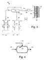
- Fig. 3 shows a multiple fuel delivery system 100 as may be described herein.
- the multiple fuel delivery system 100 may include a first fuel tank 110.
- the first fuel tank 110 may include a volume of a diesel fuel 120 therein.
- the diesel fuel 120 may be a number two diesel fuel and the like. Other types of fuels may be used herein.
- the first fuel tank 110 may have any suitable size, shape, or configuration.
- the first fuel tank 110 may be in communication with a mixing chamber 130.
- the first fuel tank 110 may be in communication with the mixing chamber 130 via one or more first fuel pumps 140 and one or more first fuel lines 150.
- the first fuel pumps 140 may be of conventional design.
- a number of first fuel line isolation valves 160 also may be used on the first fuel lines 150. Other components and other configurations may be used herein.
- the multiple fuel delivery system 100 also may include a second fuel tank 170.
- the second fuel tank 170 may have a volume of a biodiesel fuel 180 therein. Other types of fuels may be used herein.
- the second fuel tank 170 may have any suitable size, shape, or configuration.
- the second fuel tank 170 may be in communication with the mixing chamber 130 via one or more second fuel pumps 190 positioned on one or more second fuel lines 200.
- the second fuel pumps 190 may be of conventional design.
- a number of second fuel line isolation valves 210 also may be used on the second fuel lines 200. Other components and other configurations may be used herein.
- Fig. 4 shows an example of the mixing chamber 130.
- the mixing chamber may include a number of angled counter flow nozzles 220 for the flow of the biodiesel fuel 180 or other type of secondary flow.
- the flow of the biodiesel fuel 180 may be injected at an angle via the angled counter flow nozzles 220 into the incoming flow of diesel fuel 120 or other type of primary flow for good mixing therein without the use of moving parts.
- Good mixing also may be provided by injecting the flow of biofuel diesel 180 at a higher pressure as compared to the flow of diesel fuel 120.
- the mixing chamber 130 may have any size, shape, or configuration.
- a mixing chamber valve 225 may be positioned about the mixing chamber to allow draining thereof.
- a blended flow 230 thus may exit the mixing chamber 130.
- the blended flow 230 may be pumped by a main fuel pump 240 to a flow divider 250.
- the flow divider 250 may include a number of manifolds 260 and a number of outgoing fuel lines 270.
- the outgoing fuel lines 270 may be in communication with the combustor cans 25 for combustion as described above.
- Other components and other configurations may be used herein.
- the multiple fuel delivery system 100 may be operated via a fuel optimization controller 280.
- the fuel optimization controller 280 may provide the requested fuel to the combustor cans 25 as well as the appropriate proportions for the blends thereof. The proportions may be based on a predetermined schedule or may be varied based upon operating conditions and other types of parameters.
- the fuel optimization controller 280 may be any type of programmable logic device and may be in communication with the overall control system for the gas turbine engine.
- the fuel optimization controller 280 may instruct the first fuel pump 140 to pump the diesel fuel 120 to the mixing chamber 130 and may instruct the main fuel pump 240 to pump the diesel fuel 120 to the flow divider 250. Likewise, if one hundred percent (100%) of the biodiesel fuel 180 is requested, then the fuel optimization controller 280 may instruct the second fuel pump 190 to pump the biodiesel fuel 180 to the mixing chamber 130 and may instruct the main fuel pump 240 to pump the biodiesel fuel 180 to the flow divider 250.
- the fuel optimization controller 280 may select the appropriate proportions based upon predetermined ratios or other parameters.
- the fuel optimization controller 280 may instruct the first fuel pump 140 to pump the appropriate volume of the diesel fuel 120 to the mixing chamber 130 and may instruct the second fuel pump 190 to pump the appropriate volume of the biodiesel fuel 180 to the mixing chamber 130.
- the diesel fuel 120 and the biodiesel fuel 180 may be mixed within the mixing chamber 130 with the aid of the angled counter flow nozzles 220.
- the resultant blended flow 230 may be a homogeneous mixture of the fuels in the requested ratio.
- the fuel optimization controller 280 may instruct the main fuel pump 240 to pump the blended flow 230 to the flow divider 250 for combustion in the combustion cans 25.
- the multiple fuel delivery system 100 thus may provide any ratio of the respective fuels from about zero percent (0%) to one hundred percent (100%), i.e., B20 (twenty percent (20%) biodiesel fuel 180 and eighty percent (80%) diesel fuel 120, B30 (thirty percent (30%) biodiesel fuel 180 and seventy percent (70%) diesel fuel 120, and so forth. Moreover, the ratios may change based upon operating conditions and other parameters herein.
- the multiple fuel delivery system 300 may include a first fuel tank 310.
- the first fuel tank 310 may include a volume of a diesel fuel 320.
- the diesel fuel 320 may be a number two diesel fuel, a biodiesel fuel, and the like. Other types of fuels may be used herein.
- the first fuel tank 310 may have been a suitable size, shape, or configuration.
- the first fuel tank 310 may be in communication with a mixing chamber 330.
- the mixing chamber 330 may be similar to the mixing chamber 130 described above.
- the first fuel tank 310 may be in communication with the mixing chamber 330 via one or more first fuel pumps 340 on one or more first fuel lines 350.
- the first fuel pumps 340 may be of conventional design.
- a number of first fuel line isolation valves 360 may be used on the first fuel lines 350.
- Other components and other configurations may be used herein.
- the multiple fuel delivery system 300 also may include a second fuel tank 370.
- the second fuel tank 370 may have a volume of a naphtha fuel 380 therein. Other types of fuels may be used herein.
- the second fuel tank 370 may have any suitable size, shape, or configuration.
- the second fuel tank 370 may be in communication with the mixing chamber 330 via one or more second fuel pumps 390 positioned on one or more fuel lines 400.
- the second fuel pumps 390 may be of conventional design.
- a number of second fuel line isolation valves 410 may be positioned on the second fuel lines 400. Other components and other configurations may be used herein.
- one or more of the second fuel lines 400 may include a cooling blanket 420 thereon.
- the cooling blanket 420 may be used for high ambient temperature locations.
- the one or more second fuel lines 400 also may include a number of strainers or filters 430 for the flow of naphtha 380.
- a three-way filter valve 435 and a pair of downstream filter valves 436 may be used to use one of the filters 430 at a time with the redundant filter 430 to ensure high system availability and operating reliability.
- Other components and other configurations also may be used herein.
- the fuel delivery system 300 also may include a lubrication tank 440.
- the lubrication tank 440 may have a volume of a lubricity agent 450 therein. Various types of lubricity agents may be used herein.
- the lubrication tank 440 may have any suitable size, shape, or configuration.
- the lubrication tank 440 may be in communication with the second fuel lines 400 just upstream of the second fuel pumps 390.
- the lubrication tank 440 may be in communication with the second fuel lines 400 via one or more lubrication pumps 460 and one or more first lubrication lines 470.
- the lubrication pumps 460 may be of conventional design.
- a number of lubrication line isolation valves 480 may be positioned on the first lubrication lines 470.
- the lubrication tank 440 also may be in communication with or downstream of the mixing chamber 330 via a second lubrication line 490 and a three-way valve 500. Other types of joints and the like may be used herein to merge the flows. Varying volumes of the lubricity agent 450 may be used herein. Other components and other configurations may be used herein.
- the flow of naphtha 380 and the first flow of the lubricity agent 450 thus may mix upstream of the second fuel pumps 390 to create a naphtha mixture 510.
- the naphtha mixture 510 may flow via the second flow lines 350 and the filters 430 to the mixing chamber 330.
- the flow of the diesel fuel 320 may flow to the mixing chamber 330 via the first fuel lines 350.
- the naphtha mixture 510 and the flow of diesel fuel 320 may mix in the mixing chamber 330 in a manner similar to that described above.
- a blended flow 510 thus may exit the mixing chamber 330 and may be further mixed with an additional flow of lubricity agent 450 at the three-way valve 500 or elsewhere.
- the blended flow 520 may be pumped by a main fuel pump 530 to a flow divider 540 for combustion as described above.
- Other components and other configurations also may be used herein.
- the fuel optimization controller 280 may instruct the first fuel pumps 340 to pump the diesel fuel 320 to the mixing chamber 330 and may instruct the main fuel pump 530 to pump the diesel fuel 320 to the flow divider 540.
- a by-pass line 550 may by-pass the mixing chamber 330 via a number of by-pass valves 560.
- the fuel optimization controller 280 may first instruct the lubrication pump 460 to pump the lubricity agent 450 to the second fuel lines 400 and/or the three-way valve 500 to compensate for the viscosity of the naphtha 380 as well as to mitigate possible corrosion to the main fuel pump 530 and the flow divider 540. Once the lubricity agent 450 is flowing adequately, the fuel optimization controller 280 then may instruct the second fuel pumps 390 to pump the naphtha 380 to the mixing chamber 330 and may instruct the main fuel pump 530 to pump the naphtha 380 to the flow divider 540.
- the fuel optimization controller 280 may instruct the first fuel pumps 340 to pump the diesel fuel 320 to the mixing chamber 330 and may instruct the main fuel pump 530 to pump the diesel fuel 320 to the flow divider 540.
- the fuel optimization controller 280 then may instruct the lubricating pump 480 to pump the lubricity agent 450 to the second fuel lines 400 and/or to the three-way valve 500.
- the fuel optimization controller 280 then may instruct the second fuel pumps 390 to pump the naphtha 380 to the mixing chamber 330.
- the diesel fuel 320 and the naphtha 380 may mix in the mixing chamber 330.
- the blended flow 520 then may be pumped to the flow divider 530 for combustion in the combustor cans 25.
- the blend of naphtha 380 to the diesel fuel 320 may be any proportion but generally may be in the range of about five percent (5%) to about twenty percent (20%) range. The proportions may change because of operating conditions or other parameters. Other components and other configurations may be used herein.
- the multiple fuel delivery systems 100, 300 described herein thus provides the gas turbine engine with fuel flexibility to combust almost any number of different fuels and blends thereof.
- the multiple fuel delivery system 100 also may be combined with the multiple fuel delivery system 300 for further flexibility.
- Many different fuels may be used herein in any number of fuel tanks.
- a number of different cleaning techniques may be used herein to ensure that adequate removal of residual fuels as may be needed.
- a flush line 570 with a flush valve 580 may extend from the first fuel line 350 to the second fuel line 400.
- a flow of diesel fuel 320 may be used to flush the naphtha mixture 510 out of the second fuel line 400 and the filters 430 and the like.
- the fuel optimization controller 280 may monitor header pressures and flows in all lines leading to the main fuel pump 530 and elsewhere. The controller 280 thus may use this pressure and flow information to determine when to transfer to the available pumps for fuel or the lubricity agent 450 to the mixing chamber 330 for the predetermined system pressure and flow requirements. Likewise, the controller 280 may open and close the appropriate valves to purge the system when returning to the flow of only diesel fuel.
Landscapes
- Engineering & Computer Science (AREA)
- Chemical & Material Sciences (AREA)
- Combustion & Propulsion (AREA)
- Mechanical Engineering (AREA)
- General Engineering & Computer Science (AREA)
- Output Control And Ontrol Of Special Type Engine (AREA)
- Feeding And Controlling Fuel (AREA)
- Structures Of Non-Positive Displacement Pumps (AREA)
Abstract
Description
- The present application and the resultant patent relate generally to gas turbine engines and more particularly relate to a gas turbine engine with a multiple fuel delivery system such that the gas turbine engine may operate on multiple fuels and blends thereof.
- Heavy duty gas turbine engines may operate on a number of different fuels. The fuels may range from heavy oils, naphtha, distillate, flare gas, syngas, landfill gas, natural gas, and other types of fuels and/or blends thereof. Power plants thus may have gas turbine engines with dual fuel capability and may operate on, for example, diesel and natural gas, depending upon availability, price, and other operational parameters.
- Given significant fluctuations in the price of petroleum-based fuels, there is an interest in increasing the use of alternative fuels and blends thereof. For example, naphtha and the like are generally considered to be lower cost alternative fuels. Viscosity differences, however, between naphtha and diesel fuels may make it challenging to convert existing combustion systems to use naphtha. Similarly, various types of biofuels are also in increased use. Biofuels and diesel fuels, however, generally must be premixed before combustion. Such blends may be premixed in a number of different techniques that provide little flexibility in altering the specified proportions. There is thus a desire for systems and methods for the accurate preparation and delivery of multiple fuels and blends thereof to a gas turbine engine. Such systems and methods may provide fuel flexibility for the gas turbine engine to operate on multiple fuels and any type of blends thereof.
- The present application and the resultant patent thus provide a multiple fuel delivery system for use with a gas turbine engine. The multiple fuel delivery system may include a first fuel tank with a first fuel therein, a second fuel tank with a second fuel therein, a mixing chamber, and a flow divider downstream of the mixing chamber. The first fuel tank may be in communication with the mixing chamber via a first fuel pump and the second fuel tank may be in communication with the mixing chamber via a second fuel pump.
- The present application and the resultant patent further provide a method of operating a multiple fuel delivery system for a gas turbine engine. The method may include the steps of providing a volume of a first fuel, providing a volume of a second fuel, selecting a ratio of the first fuel and the second fuel, pumping the ratio of the first fuel and the second fuel to a mixing chamber to create a blended flow, and pumping the blended flow to a flow divider for combustion in the gas turbine engine.
- The present application and the resultant patent further may provide a multiple fuel delivery system for use with a gas turbine engine. The multiple fuel delivery system may include a first fuel tank with a first fuel therein, a second fuel tank with a second fuel therein, a mixing chamber with one or more angled counter flow nozzles so as to create a blended flow, and a flow divider downstream of the mixing chamber. The first fuel tank may be communication with the mixing chamber via a first fuel pump and the second fuel tank may be in communication with the mixing chamber via a second fuel pump. The flow divider may provide the blended flow to a number of combustor cans of the gas turbine engine.
- These and other features and improvements of the present application and the resultant patent will become apparent to one of ordinary skill in the art upon review of the following detailed description when taken in conjunction with the several drawings and the appended claims.
-
-
Fig. 1 is a schematic view of a gas turbine engine showing a compressor, a combustor, a turbine, and a load. -
Fig. 2 is a schematic view of a fuel delivery system for use with a combustor. -
Fig. 3 is a schematic view of a multiple fuel delivery system as may be described herein. -
Fig. 4 is a schematic view of a mixing chamber as may be used in the multiple fuel delivery system ofFig. 3 . -
Fig. 5 is a schematic view of an alternative embodiment of a multiple fuel delivery system as may be described herein. - Referring now to the drawings, in which like numerals refer to like elements throughout the several views,
Fig. 1 shows a schematic view ofgas turbine engine 10 as may be used herein. Thegas turbine engine 10 includes acompressor 15. Thecompressor 15 compresses an incoming flow ofair 20. Thecompressor 15 delivers the compressed flow ofair 20 to a number ofcombustor cans 25. The combustor cans 25 mix the compressed flow ofair 20 with a pressurized flow offuel 30 and ignite the mixture to create a flow ofcombustion gases 35. Although only a single combustor can 25 is shown, thegas turbine engine 10 may include any number ofcombustor cans 25. The flow ofcombustion gases 35 is in turn delivered to aturbine 40. The flow ofcombustion gases 35 drives theturbine 40 so as to produce mechanical work. The mechanical work produced in theturbine 40 drives thecompressor 15 via ashaft 45 and anexternal load 50 such as an electrical generator and the like. - The
gas turbine engine 10 may use natural gas, diesel fuels, various types of syngas, and/or other types of fuels. Thegas turbine engine 10 may be any one of a number of different gas turbine engines offered by General Electric Company of Schenectady, New York, including, but not limited to, those such as a frame-7 or a frame-9 series heavy duty gas turbine engine and the like. Thegas turbine engine 10 may have different configurations and may use other types of components. Other types of gas turbine engines also may be used herein. Multiple gas turbine engines, other types of turbines, and other types of power generation equipment also may be used herein together. -
Fig. 2 shows afuel delivery system 55 that may be used with thecombustor 25. When using a fuel blend, such as a diesel fuel and naphtha, the fuels may be premixed in amixing tank 60 or elsewhere. The blended fuel may be pumped by afuel pump 65 to aflow divider 70. Theflow divider 70 may divide the flow of fuel according to the number ofcombustor cans 25 in use. Theflow divider 70 may include a number ofmanifolds 75 and a number ofoutgoing fuel lines 80 in communication with thecombustor cans 25. The flow of fuel may be mixed with a number of other flows in a three-way valve 85 and the like and distributed to a number of thefuel nozzles 90 within thecombustor cans 25 via adistribution valve 95 and the like. Thefuel delivery system 55 described herein is for the purpose of example only. Many other types and configurations of fuel delivery systems may be known. -
Fig. 3 shows a multiplefuel delivery system 100 as may be described herein. The multiplefuel delivery system 100 may include afirst fuel tank 110. In this example, thefirst fuel tank 110 may include a volume of adiesel fuel 120 therein. Thediesel fuel 120 may be a number two diesel fuel and the like. Other types of fuels may be used herein. Thefirst fuel tank 110 may have any suitable size, shape, or configuration. Thefirst fuel tank 110 may be in communication with amixing chamber 130. Thefirst fuel tank 110 may be in communication with themixing chamber 130 via one or morefirst fuel pumps 140 and one or morefirst fuel lines 150. Thefirst fuel pumps 140 may be of conventional design. A number of first fuelline isolation valves 160 also may be used on thefirst fuel lines 150. Other components and other configurations may be used herein. - The multiple
fuel delivery system 100 also may include asecond fuel tank 170. Thesecond fuel tank 170 may have a volume of abiodiesel fuel 180 therein. Other types of fuels may be used herein. Thesecond fuel tank 170 may have any suitable size, shape, or configuration. Thesecond fuel tank 170 may be in communication with the mixingchamber 130 via one or moresecond fuel pumps 190 positioned on one or more second fuel lines 200. Thesecond fuel pumps 190 may be of conventional design. A number of second fuelline isolation valves 210 also may be used on the second fuel lines 200. Other components and other configurations may be used herein. -
Fig. 4 shows an example of the mixingchamber 130. The mixing chamber may include a number of angledcounter flow nozzles 220 for the flow of thebiodiesel fuel 180 or other type of secondary flow. The flow of thebiodiesel fuel 180 may be injected at an angle via the angledcounter flow nozzles 220 into the incoming flow ofdiesel fuel 120 or other type of primary flow for good mixing therein without the use of moving parts. Good mixing also may be provided by injecting the flow ofbiofuel diesel 180 at a higher pressure as compared to the flow ofdiesel fuel 120. The mixingchamber 130 may have any size, shape, or configuration. A mixingchamber valve 225 may be positioned about the mixing chamber to allow draining thereof. - A blended
flow 230 thus may exit the mixingchamber 130. The blendedflow 230 may be pumped by amain fuel pump 240 to aflow divider 250. As described above, theflow divider 250 may include a number ofmanifolds 260 and a number of outgoing fuel lines 270. Theoutgoing fuel lines 270 may be in communication with thecombustor cans 25 for combustion as described above. Other components and other configurations may be used herein. - The multiple
fuel delivery system 100 may be operated via afuel optimization controller 280. Thefuel optimization controller 280 may provide the requested fuel to thecombustor cans 25 as well as the appropriate proportions for the blends thereof. The proportions may be based on a predetermined schedule or may be varied based upon operating conditions and other types of parameters. Thefuel optimization controller 280 may be any type of programmable logic device and may be in communication with the overall control system for the gas turbine engine. - In use, if one hundred percent (100%) of the
diesel fuel 120 is requested, thefuel optimization controller 280 may instruct thefirst fuel pump 140 to pump thediesel fuel 120 to the mixingchamber 130 and may instruct themain fuel pump 240 to pump thediesel fuel 120 to theflow divider 250. Likewise, if one hundred percent (100%) of thebiodiesel fuel 180 is requested, then thefuel optimization controller 280 may instruct thesecond fuel pump 190 to pump thebiodiesel fuel 180 to the mixingchamber 130 and may instruct themain fuel pump 240 to pump thebiodiesel fuel 180 to theflow divider 250. - If a blend of fuels is requested, the
fuel optimization controller 280 may select the appropriate proportions based upon predetermined ratios or other parameters. Thefuel optimization controller 280 may instruct thefirst fuel pump 140 to pump the appropriate volume of thediesel fuel 120 to the mixingchamber 130 and may instruct thesecond fuel pump 190 to pump the appropriate volume of thebiodiesel fuel 180 to the mixingchamber 130. Thediesel fuel 120 and thebiodiesel fuel 180 may be mixed within the mixingchamber 130 with the aid of the angledcounter flow nozzles 220. The resultant blendedflow 230 may be a homogeneous mixture of the fuels in the requested ratio. Thefuel optimization controller 280 may instruct themain fuel pump 240 to pump the blendedflow 230 to theflow divider 250 for combustion in thecombustion cans 25. The multiplefuel delivery system 100 thus may provide any ratio of the respective fuels from about zero percent (0%) to one hundred percent (100%), i.e., B20 (twenty percent (20%)biodiesel fuel 180 and eighty percent (80%)diesel fuel 120, B30 (thirty percent (30%)biodiesel fuel 180 and seventy percent (70%)diesel fuel 120, and so forth. Moreover, the ratios may change based upon operating conditions and other parameters herein. -
Fig. 5 shows a further embodiment of a multiplefuel delivery system 300 as may be described herein. The multiplefuel delivery system 300 may include afirst fuel tank 310. Thefirst fuel tank 310 may include a volume of adiesel fuel 320. Thediesel fuel 320 may be a number two diesel fuel, a biodiesel fuel, and the like. Other types of fuels may be used herein. Thefirst fuel tank 310 may have been a suitable size, shape, or configuration. Thefirst fuel tank 310 may be in communication with a mixingchamber 330. The mixingchamber 330 may be similar to the mixingchamber 130 described above. Thefirst fuel tank 310 may be in communication with the mixingchamber 330 via one or morefirst fuel pumps 340 on one or more first fuel lines 350. Thefirst fuel pumps 340 may be of conventional design. A number of first fuelline isolation valves 360 may be used on the first fuel lines 350. Other components and other configurations may be used herein. - The multiple
fuel delivery system 300 also may include asecond fuel tank 370. Thesecond fuel tank 370 may have a volume of anaphtha fuel 380 therein. Other types of fuels may be used herein. Thesecond fuel tank 370 may have any suitable size, shape, or configuration. Thesecond fuel tank 370 may be in communication with the mixingchamber 330 via one or moresecond fuel pumps 390 positioned on one ormore fuel lines 400. Thesecond fuel pumps 390 may be of conventional design. A number of second fuelline isolation valves 410 may be positioned on the second fuel lines 400. Other components and other configurations may be used herein. - Due to the nature of the
naphtha 380, one or more of thesecond fuel lines 400 may include acooling blanket 420 thereon. The coolingblanket 420 may be used for high ambient temperature locations. The one or moresecond fuel lines 400 also may include a number of strainers orfilters 430 for the flow ofnaphtha 380. A three-way filter valve 435 and a pair ofdownstream filter valves 436 may be used to use one of thefilters 430 at a time with theredundant filter 430 to ensure high system availability and operating reliability. Other components and other configurations also may be used herein. - The
fuel delivery system 300 also may include alubrication tank 440. Thelubrication tank 440 may have a volume of alubricity agent 450 therein. Various types of lubricity agents may be used herein. Thelubrication tank 440 may have any suitable size, shape, or configuration. Thelubrication tank 440 may be in communication with thesecond fuel lines 400 just upstream of the second fuel pumps 390. Thelubrication tank 440 may be in communication with thesecond fuel lines 400 via one or more lubrication pumps 460 and one or more first lubrication lines 470. The lubrication pumps 460 may be of conventional design. A number of lubricationline isolation valves 480 may be positioned on the first lubrication lines 470. Thelubrication tank 440 also may be in communication with or downstream of the mixingchamber 330 via asecond lubrication line 490 and a three-way valve 500. Other types of joints and the like may be used herein to merge the flows. Varying volumes of thelubricity agent 450 may be used herein. Other components and other configurations may be used herein. - The flow of
naphtha 380 and the first flow of thelubricity agent 450 thus may mix upstream of thesecond fuel pumps 390 to create anaphtha mixture 510. Thenaphtha mixture 510 may flow via thesecond flow lines 350 and thefilters 430 to the mixingchamber 330. Likewise, the flow of thediesel fuel 320 may flow to the mixingchamber 330 via the first fuel lines 350. Thenaphtha mixture 510 and the flow ofdiesel fuel 320 may mix in the mixingchamber 330 in a manner similar to that described above. A blendedflow 510 thus may exit the mixingchamber 330 and may be further mixed with an additional flow oflubricity agent 450 at the three-way valve 500 or elsewhere. The blendedflow 520 may be pumped by amain fuel pump 530 to aflow divider 540 for combustion as described above. Other components and other configurations also may be used herein. - In use, if one hundred percent (100%) of the
diesel fuel 320 is requested, then thefuel optimization controller 280 may instruct thefirst fuel pumps 340 to pump thediesel fuel 320 to the mixingchamber 330 and may instruct themain fuel pump 530 to pump thediesel fuel 320 to theflow divider 540. Alternatively, a by-pass line 550 may by-pass the mixingchamber 330 via a number of by-pass valves 560. If one hundred percent (100%) of thenaphtha 380 is requested, thefuel optimization controller 280 may first instruct thelubrication pump 460 to pump thelubricity agent 450 to thesecond fuel lines 400 and/or the three-way valve 500 to compensate for the viscosity of thenaphtha 380 as well as to mitigate possible corrosion to themain fuel pump 530 and theflow divider 540. Once thelubricity agent 450 is flowing adequately, thefuel optimization controller 280 then may instruct thesecond fuel pumps 390 to pump thenaphtha 380 to the mixingchamber 330 and may instruct themain fuel pump 530 to pump thenaphtha 380 to theflow divider 540. - If a blend of the
diesel fuel 320 and thenaphtha 380 is requested, naphtha is generally not utilized as a startup fuel. As such, thefuel optimization controller 280 may instruct thefirst fuel pumps 340 to pump thediesel fuel 320 to the mixingchamber 330 and may instruct themain fuel pump 530 to pump thediesel fuel 320 to theflow divider 540. Thefuel optimization controller 280 then may instruct thelubricating pump 480 to pump thelubricity agent 450 to thesecond fuel lines 400 and/or to the three-way valve 500. Thefuel optimization controller 280 then may instruct thesecond fuel pumps 390 to pump thenaphtha 380 to the mixingchamber 330. Thediesel fuel 320 and thenaphtha 380 may mix in the mixingchamber 330. The blendedflow 520 then may be pumped to theflow divider 530 for combustion in thecombustor cans 25. The blend ofnaphtha 380 to thediesel fuel 320 may be any proportion but generally may be in the range of about five percent (5%) to about twenty percent (20%) range. The proportions may change because of operating conditions or other parameters. Other components and other configurations may be used herein. - The multiple
fuel delivery systems fuel delivery system 100 also may be combined with the multiplefuel delivery system 300 for further flexibility. Many different fuels may be used herein in any number of fuel tanks. A number of different cleaning techniques may be used herein to ensure that adequate removal of residual fuels as may be needed. For example, aflush line 570 with aflush valve 580 may extend from thefirst fuel line 350 to thesecond fuel line 400. A flow ofdiesel fuel 320 may be used to flush thenaphtha mixture 510 out of thesecond fuel line 400 and thefilters 430 and the like. - All of the pumps and valves described herein are redundant to provide for availability and reliability. Only one pump and valve combination may be in use at any given time. The
fuel optimization controller 280 may monitor header pressures and flows in all lines leading to themain fuel pump 530 and elsewhere. Thecontroller 280 thus may use this pressure and flow information to determine when to transfer to the available pumps for fuel or thelubricity agent 450 to the mixingchamber 330 for the predetermined system pressure and flow requirements. Likewise, thecontroller 280 may open and close the appropriate valves to purge the system when returning to the flow of only diesel fuel.
Claims (15)
- A multiple fuel delivery system (100) for use with a gas turbine engine, comprising:a first fuel tank (110) with a first fuel (120) therein;a second fuel tank (170) with a second fuel (180) therein;a mixing chamber (130);the first fuel tank in communication with the mixing chamber via a first fuel pump (140);the second fuel tank in communication with the mixing chamber via a second fuel pump (190); anda flow divider (250) downstream of the mixing chamber.
- The multiple fuel delivery system of claim 1, wherein the first fuel comprises a diesel fuel and wherein the second fuel comprises a biodiesel fuel.
- The multiple fuel delivery system of claim 1 or claim 2, wherein the mixing chamber comprises one or more angled counter flow nozzles (220).
- The multiple fuel delivery system of any preceding claim, further comprising a fuel optimization controller (280) in communication with the first pump, the second pump, and a main fuel pump (240).
- The multiple fuel delivery system of claim 1, wherein the first fuel comprises a diesel fuel and wherein the second fuel comprises a naphtha fuel.
- The multiple fuel delivery system of any preceding claim, further comprising a lubrication tank (440) with a volume of a lubricity agent therein.
- The multiple fuel delivery system of claim 6, wherein the lubrication tank is in communication with the second pump via a lubrication pump (460).
- The multiple fuel delivery system of claim 6 or claim 7, wherein the lubrication tank is in communication with the mixing chamber via a lubrication pump.
- The multiple fuel delivery system of any one of claims 6 to 8, wherein the lubrication tank is in communication with a three way valve (500) downstream of the mixing chamber.
- The multiple fuel delivery system of any preceding claim, further comprising a filter (430) downstream of the second fuel pump.
- The multiple fuel delivery system of any preceding claim, further comprising a cooling blanket (420) downstream of the second fuel pump.
- The multiple fuel delivery system of any preceding claim, wherein the flow divider (250) comprises one or more fuel lines in communication with one or more combustion cans of the gas turbine engine.
- The multiple fuel delivery system of any preceding claim, wherein a proportion of the first fuel to the second fuel ranges from about zero percent to one hundred percent.
- The multiple fuel delivery system of any one of claims 1 to 12, wherein a proportion of the second fuel to the first fuel ranges from about zero percent to one hundred percent.
- A method of operating a multiple fuel delivery system for a gas turbine engine, comprising:providing a volume of a first fuel (120);providing a volume of a second fuel (180);selecting a ratio of the first fuel and the second fuel;pumping the ratio of the first fuel and the second fuel to a mixing chamber (130) to create a blended flow; andpumping the blended flow to a flow divider (250) for combustion in the gas turbine engine.
Applications Claiming Priority (1)
| Application Number | Priority Date | Filing Date | Title |
|---|---|---|---|
| US13/645,536 US10156192B2 (en) | 2012-10-05 | 2012-10-05 | Gas turbine engine with a multiple fuel delivery system |
Publications (3)
| Publication Number | Publication Date |
|---|---|
| EP2716890A2 true EP2716890A2 (en) | 2014-04-09 |
| EP2716890A3 EP2716890A3 (en) | 2017-08-02 |
| EP2716890B1 EP2716890B1 (en) | 2020-02-26 |
Family
ID=49322215
Family Applications (1)
| Application Number | Title | Priority Date | Filing Date |
|---|---|---|---|
| EP13187110.5A Active EP2716890B1 (en) | 2012-10-05 | 2013-10-02 | Gas turbine engine with a multiple fuel delivery system |
Country Status (4)
| Country | Link |
|---|---|
| US (1) | US10156192B2 (en) |
| EP (1) | EP2716890B1 (en) |
| JP (1) | JP6280338B2 (en) |
| CN (1) | CN203742794U (en) |
Cited By (3)
| Publication number | Priority date | Publication date | Assignee | Title |
|---|---|---|---|---|
| EP3156628A1 (en) * | 2015-10-15 | 2017-04-19 | General Electric Company | Controlling injection of bio-diesel into a gas turbine combustor |
| US10731569B2 (en) | 2015-10-15 | 2020-08-04 | General Electric Company | Systems and methods for injection of bio-diesel into a gas turbine combustor |
| WO2021086715A1 (en) * | 2019-10-30 | 2021-05-06 | General Electric Company | System and method for operating a combustor with multiple liquid fuels |
Families Citing this family (5)
| Publication number | Priority date | Publication date | Assignee | Title |
|---|---|---|---|---|
| US10247110B2 (en) * | 2015-09-23 | 2019-04-02 | General Electric Company | Method and system for reliable gas to liquid transfer |
| US20170089265A1 (en) * | 2015-09-25 | 2017-03-30 | General Electric Company | Liquefied petroleum gas fuel conditioning system for gas turbine engines |
| DE102021104092A1 (en) | 2021-02-22 | 2022-08-25 | Deutsches Zentrum für Luft- und Raumfahrt e.V. | Method of operating an aircraft depending on an operating mode |
| CN113864063A (en) * | 2021-09-28 | 2021-12-31 | 永旭腾风新能源动力科技(北京)有限公司 | Dual-fuel system for micro-combustion engine, micro-combustion engine and control method thereof |
| CN113864064A (en) * | 2021-09-28 | 2021-12-31 | 永旭腾风新能源动力科技(北京)有限公司 | Fuel supply system with dual fuel system and micro gas turbine |
Family Cites Families (23)
| Publication number | Priority date | Publication date | Assignee | Title |
|---|---|---|---|---|
| JPS5396531A (en) * | 1977-02-02 | 1978-08-23 | Hitachi Ltd | Fuel oil blend system |
| DE3843543C2 (en) * | 1988-12-23 | 2000-11-23 | Thyssen Gas | Process for the reduction of nitrogen oxides contained in flue gases from combustion plants |
| JPH07224688A (en) * | 1994-02-09 | 1995-08-22 | Mitsubishi Heavy Ind Ltd | Fuel supply method for gas turbine |
| US20030163994A1 (en) * | 2001-12-21 | 2003-09-04 | Kabushiki Kaisha Meidensha | Generator set for vegetable oil and method of operating the same |
| CN100587043C (en) | 2003-04-11 | 2010-02-03 | Sasol技术股份有限公司 | Low sulphur diesel fuel and aviation turbine fuel |
| JP4119864B2 (en) * | 2004-03-31 | 2008-07-16 | 三菱重工業株式会社 | Fuel injection device for internal combustion engine |
| US7458998B2 (en) * | 2004-08-23 | 2008-12-02 | Flint Hills Resources, L.P. | Blending biodiesel with diesel fuel in cold locations |
| JP2006112670A (en) * | 2004-10-12 | 2006-04-27 | Mitsubishi Heavy Ind Ltd | Liquid fuel nozzle |
| JP2006233920A (en) * | 2005-02-28 | 2006-09-07 | Mitsubishi Heavy Ind Ltd | System for controlling calorific value of fuel gas and gas-turbine system |
| US7861696B2 (en) * | 2005-11-26 | 2011-01-04 | Exen Holdings, Llc | Multi fuel co-injection system for internal combustion and turbine engines |
| GB0620925D0 (en) * | 2006-10-20 | 2006-11-29 | Renewable Holdings Ltd | Biodiesel synthesis |
| US7964000B2 (en) | 2006-11-30 | 2011-06-21 | Flint Hills Resources, L.P. | Biodiesel fuel blend |
| EP2209737A2 (en) * | 2007-10-26 | 2010-07-28 | Amyris Biotechnologies, Inc. | Fuel composition dispensing system |
| EP2072899B1 (en) * | 2007-12-19 | 2016-03-30 | Alstom Technology Ltd | Fuel injection method |
| EP2262874A4 (en) | 2008-04-06 | 2011-09-28 | Uop Llc | Fuel and fuel blending components from biomass derived pyrolysis oil |
| US20110126448A1 (en) * | 2008-12-17 | 2011-06-02 | BP Biofuels UK Limited | Process, Plant, and Biofuel For Integrated Biofuel Production |
| US8234870B2 (en) * | 2009-04-17 | 2012-08-07 | Hamilton Sundstrand Corporation | Additive injection system for improving thermal stability of jet fuel |
| DE102009052047B4 (en) * | 2009-11-05 | 2014-01-16 | Airbus Operations Gmbh | Control unit and method for regulating the supply of a multi-fuel vehicle |
| US8650851B2 (en) * | 2010-01-05 | 2014-02-18 | General Electric Company | Systems and methods for controlling fuel flow within a machine |
| US8783007B2 (en) * | 2010-05-04 | 2014-07-22 | General Electric Company | Liquid fuel system and method |
| JP4634538B1 (en) | 2010-05-27 | 2011-02-23 | 住友商事株式会社 | Hybrid thermal power generation system and construction method thereof |
| GB201211058D0 (en) * | 2012-06-22 | 2012-08-01 | Rolls Royce Plc | Fuel system |
| GB201211064D0 (en) * | 2012-06-22 | 2012-08-01 | Rolls Royce Plc | Fuel system |
-
2012
- 2012-10-05 US US13/645,536 patent/US10156192B2/en active Active
-
2013
- 2013-09-29 CN CN201320605782.2U patent/CN203742794U/en not_active Expired - Lifetime
- 2013-09-30 JP JP2013202866A patent/JP6280338B2/en active Active
- 2013-10-02 EP EP13187110.5A patent/EP2716890B1/en active Active
Non-Patent Citations (1)
| Title |
|---|
| None |
Cited By (3)
| Publication number | Priority date | Publication date | Assignee | Title |
|---|---|---|---|---|
| EP3156628A1 (en) * | 2015-10-15 | 2017-04-19 | General Electric Company | Controlling injection of bio-diesel into a gas turbine combustor |
| US10731569B2 (en) | 2015-10-15 | 2020-08-04 | General Electric Company | Systems and methods for injection of bio-diesel into a gas turbine combustor |
| WO2021086715A1 (en) * | 2019-10-30 | 2021-05-06 | General Electric Company | System and method for operating a combustor with multiple liquid fuels |
Also Published As
| Publication number | Publication date |
|---|---|
| US10156192B2 (en) | 2018-12-18 |
| EP2716890B1 (en) | 2020-02-26 |
| CN203742794U (en) | 2014-07-30 |
| US20140096827A1 (en) | 2014-04-10 |
| JP2014077440A (en) | 2014-05-01 |
| EP2716890A3 (en) | 2017-08-02 |
| JP6280338B2 (en) | 2018-02-14 |
Similar Documents
| Publication | Publication Date | Title |
|---|---|---|
| US10156192B2 (en) | Gas turbine engine with a multiple fuel delivery system | |
| Nascimento et al. | Micro gas turbine engine: a review | |
| EP2620615A2 (en) | Naphtha and process gas/syngas mixture firing method for gas turbine engines | |
| US20150119611A1 (en) | Bio-Diesel Blending System | |
| US8783007B2 (en) | Liquid fuel system and method | |
| EP2592250A2 (en) | System for purging gas fuel circuit for a gas turbine engine | |
| EP2613035A2 (en) | Environmental control system for aircraft utilizing turbo-compressor | |
| JP2011247259A (en) | Fuel pumping system for gas turbine engine | |
| US10066632B2 (en) | Inlet bleed heat control system | |
| US20140230402A1 (en) | Turbine conduit purge systems | |
| EP3161293A1 (en) | Method and system for startup of gas turbine system drive trains with exhaust gas recirculation | |
| GB2510662A (en) | A fuel metering valve system for a gas turbine engine | |
| EP3147480A1 (en) | Liquefied petroleum gas fuel conditioning system for gas turbine engines | |
| EP3187782A1 (en) | Systems and methods for mitigating the impact of vanadium in heavy fuel oil | |
| EP4261138A1 (en) | Aircraft refuelling | |
| US9243564B2 (en) | Systems and methods for removing impurities from heavy fuel oil | |
| GB2619394A (en) | Propulsion system | |
| US20110314833A1 (en) | Additive injection system for use with a turbine engine and methods of assembling same | |
| EP2631453A2 (en) | Fuel purging system for a turbine assembly | |
| CN116291899A (en) | Variable inlet guide vane | |
| WO2023140891A3 (en) | Turbine engines having hydrogen fuel systems | |
| EP2623740A2 (en) | Method for transferring fuel | |
| US9279370B2 (en) | Turbomachine and method of operating a turbomachine to perform a fuel change over at a high load | |
| CN210440093U (en) | Oil supply system of steam turbine generator unit | |
| US8387354B2 (en) | Oil varnish mitigation systems |
Legal Events
| Date | Code | Title | Description |
|---|---|---|---|
| PUAI | Public reference made under article 153(3) epc to a published international application that has entered the european phase |
Free format text: ORIGINAL CODE: 0009012 |
|
| AK | Designated contracting states |
Kind code of ref document: A2 Designated state(s): AL AT BE BG CH CY CZ DE DK EE ES FI FR GB GR HR HU IE IS IT LI LT LU LV MC MK MT NL NO PL PT RO RS SE SI SK SM TR |
|
| AX | Request for extension of the european patent |
Extension state: BA ME |
|
| PUAL | Search report despatched |
Free format text: ORIGINAL CODE: 0009013 |
|
| AK | Designated contracting states |
Kind code of ref document: A3 Designated state(s): AL AT BE BG CH CY CZ DE DK EE ES FI FR GB GR HR HU IE IS IT LI LT LU LV MC MK MT NL NO PL PT RO RS SE SI SK SM TR |
|
| AX | Request for extension of the european patent |
Extension state: BA ME |
|
| RIC1 | Information provided on ipc code assigned before grant |
Ipc: F02C 9/40 20060101ALI20170629BHEP Ipc: F02C 7/236 20060101ALI20170629BHEP Ipc: F02C 7/22 20060101AFI20170629BHEP Ipc: F02C 7/228 20060101ALI20170629BHEP |
|
| STAA | Information on the status of an ep patent application or granted ep patent |
Free format text: STATUS: REQUEST FOR EXAMINATION WAS MADE |
|
| 17P | Request for examination filed |
Effective date: 20180202 |
|
| RBV | Designated contracting states (corrected) |
Designated state(s): AL AT BE BG CH CY CZ DE DK EE ES FI FR GB GR HR HU IE IS IT LI LT LU LV MC MK MT NL NO PL PT RO RS SE SI SK SM TR |
|
| STAA | Information on the status of an ep patent application or granted ep patent |
Free format text: STATUS: EXAMINATION IS IN PROGRESS |
|
| 17Q | First examination report despatched |
Effective date: 20181114 |
|
| GRAP | Despatch of communication of intention to grant a patent |
Free format text: ORIGINAL CODE: EPIDOSNIGR1 |
|
| STAA | Information on the status of an ep patent application or granted ep patent |
Free format text: STATUS: GRANT OF PATENT IS INTENDED |
|
| INTG | Intention to grant announced |
Effective date: 20190916 |
|
| GRAS | Grant fee paid |
Free format text: ORIGINAL CODE: EPIDOSNIGR3 |
|
| GRAA | (expected) grant |
Free format text: ORIGINAL CODE: 0009210 |
|
| STAA | Information on the status of an ep patent application or granted ep patent |
Free format text: STATUS: THE PATENT HAS BEEN GRANTED |
|
| AK | Designated contracting states |
Kind code of ref document: B1 Designated state(s): AL AT BE BG CH CY CZ DE DK EE ES FI FR GB GR HR HU IE IS IT LI LT LU LV MC MK MT NL NO PL PT RO RS SE SI SK SM TR |
|
| REG | Reference to a national code |
Ref country code: GB Ref legal event code: FG4D |
|
| REG | Reference to a national code |
Ref country code: CH Ref legal event code: EP |
|
| REG | Reference to a national code |
Ref country code: AT Ref legal event code: REF Ref document number: 1237900 Country of ref document: AT Kind code of ref document: T Effective date: 20200315 |
|
| REG | Reference to a national code |
Ref country code: IE Ref legal event code: FG4D |
|
| REG | Reference to a national code |
Ref country code: DE Ref legal event code: R096 Ref document number: 602013066185 Country of ref document: DE |
|
| PG25 | Lapsed in a contracting state [announced via postgrant information from national office to epo] |
Ref country code: RS Free format text: LAPSE BECAUSE OF FAILURE TO SUBMIT A TRANSLATION OF THE DESCRIPTION OR TO PAY THE FEE WITHIN THE PRESCRIBED TIME-LIMIT Effective date: 20200226 Ref country code: FI Free format text: LAPSE BECAUSE OF FAILURE TO SUBMIT A TRANSLATION OF THE DESCRIPTION OR TO PAY THE FEE WITHIN THE PRESCRIBED TIME-LIMIT Effective date: 20200226 Ref country code: NO Free format text: LAPSE BECAUSE OF FAILURE TO SUBMIT A TRANSLATION OF THE DESCRIPTION OR TO PAY THE FEE WITHIN THE PRESCRIBED TIME-LIMIT Effective date: 20200526 |
|
| REG | Reference to a national code |
Ref country code: NL Ref legal event code: MP Effective date: 20200226 |
|
| REG | Reference to a national code |
Ref country code: LT Ref legal event code: MG4D |
|
| PG25 | Lapsed in a contracting state [announced via postgrant information from national office to epo] |
Ref country code: HR Free format text: LAPSE BECAUSE OF FAILURE TO SUBMIT A TRANSLATION OF THE DESCRIPTION OR TO PAY THE FEE WITHIN THE PRESCRIBED TIME-LIMIT Effective date: 20200226 Ref country code: BG Free format text: LAPSE BECAUSE OF FAILURE TO SUBMIT A TRANSLATION OF THE DESCRIPTION OR TO PAY THE FEE WITHIN THE PRESCRIBED TIME-LIMIT Effective date: 20200526 Ref country code: LV Free format text: LAPSE BECAUSE OF FAILURE TO SUBMIT A TRANSLATION OF THE DESCRIPTION OR TO PAY THE FEE WITHIN THE PRESCRIBED TIME-LIMIT Effective date: 20200226 Ref country code: SE Free format text: LAPSE BECAUSE OF FAILURE TO SUBMIT A TRANSLATION OF THE DESCRIPTION OR TO PAY THE FEE WITHIN THE PRESCRIBED TIME-LIMIT Effective date: 20200226 Ref country code: IS Free format text: LAPSE BECAUSE OF FAILURE TO SUBMIT A TRANSLATION OF THE DESCRIPTION OR TO PAY THE FEE WITHIN THE PRESCRIBED TIME-LIMIT Effective date: 20200626 Ref country code: GR Free format text: LAPSE BECAUSE OF FAILURE TO SUBMIT A TRANSLATION OF THE DESCRIPTION OR TO PAY THE FEE WITHIN THE PRESCRIBED TIME-LIMIT Effective date: 20200527 |
|
| PG25 | Lapsed in a contracting state [announced via postgrant information from national office to epo] |
Ref country code: NL Free format text: LAPSE BECAUSE OF FAILURE TO SUBMIT A TRANSLATION OF THE DESCRIPTION OR TO PAY THE FEE WITHIN THE PRESCRIBED TIME-LIMIT Effective date: 20200226 |
|
| PG25 | Lapsed in a contracting state [announced via postgrant information from national office to epo] |
Ref country code: CZ Free format text: LAPSE BECAUSE OF FAILURE TO SUBMIT A TRANSLATION OF THE DESCRIPTION OR TO PAY THE FEE WITHIN THE PRESCRIBED TIME-LIMIT Effective date: 20200226 Ref country code: RO Free format text: LAPSE BECAUSE OF FAILURE TO SUBMIT A TRANSLATION OF THE DESCRIPTION OR TO PAY THE FEE WITHIN THE PRESCRIBED TIME-LIMIT Effective date: 20200226 Ref country code: SK Free format text: LAPSE BECAUSE OF FAILURE TO SUBMIT A TRANSLATION OF THE DESCRIPTION OR TO PAY THE FEE WITHIN THE PRESCRIBED TIME-LIMIT Effective date: 20200226 Ref country code: SM Free format text: LAPSE BECAUSE OF FAILURE TO SUBMIT A TRANSLATION OF THE DESCRIPTION OR TO PAY THE FEE WITHIN THE PRESCRIBED TIME-LIMIT Effective date: 20200226 Ref country code: DK Free format text: LAPSE BECAUSE OF FAILURE TO SUBMIT A TRANSLATION OF THE DESCRIPTION OR TO PAY THE FEE WITHIN THE PRESCRIBED TIME-LIMIT Effective date: 20200226 Ref country code: EE Free format text: LAPSE BECAUSE OF FAILURE TO SUBMIT A TRANSLATION OF THE DESCRIPTION OR TO PAY THE FEE WITHIN THE PRESCRIBED TIME-LIMIT Effective date: 20200226 Ref country code: ES Free format text: LAPSE BECAUSE OF FAILURE TO SUBMIT A TRANSLATION OF THE DESCRIPTION OR TO PAY THE FEE WITHIN THE PRESCRIBED TIME-LIMIT Effective date: 20200226 Ref country code: LT Free format text: LAPSE BECAUSE OF FAILURE TO SUBMIT A TRANSLATION OF THE DESCRIPTION OR TO PAY THE FEE WITHIN THE PRESCRIBED TIME-LIMIT Effective date: 20200226 Ref country code: PT Free format text: LAPSE BECAUSE OF FAILURE TO SUBMIT A TRANSLATION OF THE DESCRIPTION OR TO PAY THE FEE WITHIN THE PRESCRIBED TIME-LIMIT Effective date: 20200719 |
|
| REG | Reference to a national code |
Ref country code: AT Ref legal event code: MK05 Ref document number: 1237900 Country of ref document: AT Kind code of ref document: T Effective date: 20200226 |
|
| REG | Reference to a national code |
Ref country code: DE Ref legal event code: R097 Ref document number: 602013066185 Country of ref document: DE |
|
| PLBE | No opposition filed within time limit |
Free format text: ORIGINAL CODE: 0009261 |
|
| STAA | Information on the status of an ep patent application or granted ep patent |
Free format text: STATUS: NO OPPOSITION FILED WITHIN TIME LIMIT |
|
| PG25 | Lapsed in a contracting state [announced via postgrant information from national office to epo] |
Ref country code: AT Free format text: LAPSE BECAUSE OF FAILURE TO SUBMIT A TRANSLATION OF THE DESCRIPTION OR TO PAY THE FEE WITHIN THE PRESCRIBED TIME-LIMIT Effective date: 20200226 Ref country code: IT Free format text: LAPSE BECAUSE OF FAILURE TO SUBMIT A TRANSLATION OF THE DESCRIPTION OR TO PAY THE FEE WITHIN THE PRESCRIBED TIME-LIMIT Effective date: 20200226 |
|
| 26N | No opposition filed |
Effective date: 20201127 |
|
| PG25 | Lapsed in a contracting state [announced via postgrant information from national office to epo] |
Ref country code: PL Free format text: LAPSE BECAUSE OF FAILURE TO SUBMIT A TRANSLATION OF THE DESCRIPTION OR TO PAY THE FEE WITHIN THE PRESCRIBED TIME-LIMIT Effective date: 20200226 Ref country code: SI Free format text: LAPSE BECAUSE OF FAILURE TO SUBMIT A TRANSLATION OF THE DESCRIPTION OR TO PAY THE FEE WITHIN THE PRESCRIBED TIME-LIMIT Effective date: 20200226 |
|
| REG | Reference to a national code |
Ref country code: CH Ref legal event code: PL |
|
| GBPC | Gb: european patent ceased through non-payment of renewal fee |
Effective date: 20201002 |
|
| PG25 | Lapsed in a contracting state [announced via postgrant information from national office to epo] |
Ref country code: LU Free format text: LAPSE BECAUSE OF NON-PAYMENT OF DUE FEES Effective date: 20201002 Ref country code: MC Free format text: LAPSE BECAUSE OF FAILURE TO SUBMIT A TRANSLATION OF THE DESCRIPTION OR TO PAY THE FEE WITHIN THE PRESCRIBED TIME-LIMIT Effective date: 20200226 |
|
| REG | Reference to a national code |
Ref country code: BE Ref legal event code: MM Effective date: 20201031 |
|
| PG25 | Lapsed in a contracting state [announced via postgrant information from national office to epo] |
Ref country code: FR Free format text: LAPSE BECAUSE OF NON-PAYMENT OF DUE FEES Effective date: 20201031 |
|
| PG25 | Lapsed in a contracting state [announced via postgrant information from national office to epo] |
Ref country code: LI Free format text: LAPSE BECAUSE OF NON-PAYMENT OF DUE FEES Effective date: 20201031 Ref country code: GB Free format text: LAPSE BECAUSE OF NON-PAYMENT OF DUE FEES Effective date: 20201002 Ref country code: CH Free format text: LAPSE BECAUSE OF NON-PAYMENT OF DUE FEES Effective date: 20201031 Ref country code: BE Free format text: LAPSE BECAUSE OF NON-PAYMENT OF DUE FEES Effective date: 20201031 |
|
| PG25 | Lapsed in a contracting state [announced via postgrant information from national office to epo] |
Ref country code: IE Free format text: LAPSE BECAUSE OF NON-PAYMENT OF DUE FEES Effective date: 20201002 |
|
| PG25 | Lapsed in a contracting state [announced via postgrant information from national office to epo] |
Ref country code: TR Free format text: LAPSE BECAUSE OF FAILURE TO SUBMIT A TRANSLATION OF THE DESCRIPTION OR TO PAY THE FEE WITHIN THE PRESCRIBED TIME-LIMIT Effective date: 20200226 Ref country code: MT Free format text: LAPSE BECAUSE OF FAILURE TO SUBMIT A TRANSLATION OF THE DESCRIPTION OR TO PAY THE FEE WITHIN THE PRESCRIBED TIME-LIMIT Effective date: 20200226 Ref country code: CY Free format text: LAPSE BECAUSE OF FAILURE TO SUBMIT A TRANSLATION OF THE DESCRIPTION OR TO PAY THE FEE WITHIN THE PRESCRIBED TIME-LIMIT Effective date: 20200226 |
|
| PG25 | Lapsed in a contracting state [announced via postgrant information from national office to epo] |
Ref country code: MK Free format text: LAPSE BECAUSE OF FAILURE TO SUBMIT A TRANSLATION OF THE DESCRIPTION OR TO PAY THE FEE WITHIN THE PRESCRIBED TIME-LIMIT Effective date: 20200226 Ref country code: AL Free format text: LAPSE BECAUSE OF FAILURE TO SUBMIT A TRANSLATION OF THE DESCRIPTION OR TO PAY THE FEE WITHIN THE PRESCRIBED TIME-LIMIT Effective date: 20200226 |
|
| REG | Reference to a national code |
Ref country code: DE Ref legal event code: R082 Ref document number: 602013066185 Country of ref document: DE Ref country code: DE Ref legal event code: R081 Ref document number: 602013066185 Country of ref document: DE Owner name: GENERAL ELECTRIC TECHNOLOGY GMBH, CH Free format text: FORMER OWNER: GENERAL ELECTRIC COMPANY, SCHENECTADY, NY, US |
|
| PGFP | Annual fee paid to national office [announced via postgrant information from national office to epo] |
Ref country code: DE Payment date: 20230920 Year of fee payment: 11 |