EP2716889A2 - Redundant cooling for fluid cooled systems - Google Patents
Redundant cooling for fluid cooled systems Download PDFInfo
- Publication number
- EP2716889A2 EP2716889A2 EP13187397.8A EP13187397A EP2716889A2 EP 2716889 A2 EP2716889 A2 EP 2716889A2 EP 13187397 A EP13187397 A EP 13187397A EP 2716889 A2 EP2716889 A2 EP 2716889A2
- Authority
- EP
- European Patent Office
- Prior art keywords
- engine
- heat exchanger
- working fluid
- airflow
- flow
- Prior art date
- Legal status (The legal status is an assumption and is not a legal conclusion. Google has not performed a legal analysis and makes no representation as to the accuracy of the status listed.)
- Granted
Links
- 239000012530 fluid Substances 0.000 title claims abstract description 80
- 238000001816 cooling Methods 0.000 title claims description 17
- 230000037361 pathway Effects 0.000 claims abstract description 24
- 239000002826 coolant Substances 0.000 claims description 52
- 238000000034 method Methods 0.000 claims description 12
- 239000000314 lubricant Substances 0.000 claims description 7
- 239000010705 motor oil Substances 0.000 description 32
- 239000003921 oil Substances 0.000 description 9
- 238000011144 upstream manufacturing Methods 0.000 description 2
- 230000004075 alteration Effects 0.000 description 1
- 238000002485 combustion reaction Methods 0.000 description 1
- 230000007257 malfunction Effects 0.000 description 1
- 238000013021 overheating Methods 0.000 description 1
- 238000006467 substitution reaction Methods 0.000 description 1
Images




Classifications
-
- F—MECHANICAL ENGINEERING; LIGHTING; HEATING; WEAPONS; BLASTING
- F02—COMBUSTION ENGINES; HOT-GAS OR COMBUSTION-PRODUCT ENGINE PLANTS
- F02C—GAS-TURBINE PLANTS; AIR INTAKES FOR JET-PROPULSION PLANTS; CONTROLLING FUEL SUPPLY IN AIR-BREATHING JET-PROPULSION PLANTS
- F02C7/00—Features, components parts, details or accessories, not provided for in, or of interest apart form groups F02C1/00 - F02C6/00; Air intakes for jet-propulsion plants
- F02C7/12—Cooling of plants
- F02C7/14—Cooling of plants of fluids in the plant, e.g. lubricant or fuel
-
- F—MECHANICAL ENGINEERING; LIGHTING; HEATING; WEAPONS; BLASTING
- F02—COMBUSTION ENGINES; HOT-GAS OR COMBUSTION-PRODUCT ENGINE PLANTS
- F02C—GAS-TURBINE PLANTS; AIR INTAKES FOR JET-PROPULSION PLANTS; CONTROLLING FUEL SUPPLY IN AIR-BREATHING JET-PROPULSION PLANTS
- F02C7/00—Features, components parts, details or accessories, not provided for in, or of interest apart form groups F02C1/00 - F02C6/00; Air intakes for jet-propulsion plants
- F02C7/12—Cooling of plants
- F02C7/14—Cooling of plants of fluids in the plant, e.g. lubricant or fuel
- F02C7/141—Cooling of plants of fluids in the plant, e.g. lubricant or fuel of working fluid
-
- F—MECHANICAL ENGINEERING; LIGHTING; HEATING; WEAPONS; BLASTING
- F02—COMBUSTION ENGINES; HOT-GAS OR COMBUSTION-PRODUCT ENGINE PLANTS
- F02C—GAS-TURBINE PLANTS; AIR INTAKES FOR JET-PROPULSION PLANTS; CONTROLLING FUEL SUPPLY IN AIR-BREATHING JET-PROPULSION PLANTS
- F02C7/00—Features, components parts, details or accessories, not provided for in, or of interest apart form groups F02C1/00 - F02C6/00; Air intakes for jet-propulsion plants
- F02C7/12—Cooling of plants
- F02C7/16—Cooling of plants characterised by cooling medium
- F02C7/18—Cooling of plants characterised by cooling medium the medium being gaseous, e.g. air
-
- Y—GENERAL TAGGING OF NEW TECHNOLOGICAL DEVELOPMENTS; GENERAL TAGGING OF CROSS-SECTIONAL TECHNOLOGIES SPANNING OVER SEVERAL SECTIONS OF THE IPC; TECHNICAL SUBJECTS COVERED BY FORMER USPC CROSS-REFERENCE ART COLLECTIONS [XRACs] AND DIGESTS
- Y02—TECHNOLOGIES OR APPLICATIONS FOR MITIGATION OR ADAPTATION AGAINST CLIMATE CHANGE
- Y02T—CLIMATE CHANGE MITIGATION TECHNOLOGIES RELATED TO TRANSPORTATION
- Y02T50/00—Aeronautics or air transport
- Y02T50/60—Efficient propulsion technologies, e.g. for aircraft
Definitions
- the present disclosure relates to vehicles, for example, rotorcraft with fluid cooled engines. More specifically, the present disclosure relates to redundant cooling systems for vehicles with fluid cooled engines or fluid cooled systems.
- Fluid cooled systems for example, internal combustion engines, require a cooling system that forces air across a heat exchanger to reject thermal energy from a working fluid that circulates through the engine.
- the cooling system must function during normal engine operation to prevent the engine from overheating that leads to engine failure.
- Such a cooling system is prone to failure of any one of the multiple components of the system, such as a fan, duct, heat exchanger or fluid distribution system including pumps and piping network. Failure or malfunction of any of these components could lead to cooling system failure and, consequently, engine failure.
- aircraft have multiple engines for redundancy to meet safety and reliability requirements if a failure of one of the engines occurs. It is difficult to meet safety and reliability requirements if a failure of one of the above components of the cooling system can result in cooling system failure.
- the individual components such as the fan, duct and heat exchanger are robustly designed to increase damage and flaw tolerance, with the penalty of additional weight, increased cost, larger component size, and loss of mission capability of the aircraft.
- a fluid cooled system includes a heat generating component.
- a first airflow pathway directs a first flow of air across a first heat exchanger.
- a second airflow pathway directs a second flow of air across a second heat exchanger.
- a working fluid is flowed from the heat generating component, through the first heat exchanger and through the second heat exchanger and returned to the heat generating component.
- Particular embodiments may include any of the following optional features, alone or in combination:
- the system further may comprise a second heat generating component; wherein a second working fluid is flowed from the second heat generating component, through the second heat exchanger and through the first heat exchanger and returned to the second heat generating component.
- the first working fluid and the second working fluid may be one of coolant or lubricant.
- the system further may comprise a first pump to urge the first working fluid through the first heat exchanger.
- the system further may comprise a fan to urge the first flow of air through the first airflow pathway.
- the fan may be driven by the first heat generating component.
- the first airflow pathway may be a first duct.
- a rotorcraft includes an airframe and a rotor assembly operably connected to the airframe including a plurality of rotor blades operably connected to a rotor shaft.
- the rotorcraft further includes a fluid cooled engine system operably connected to the rotor assembly.
- the fluid cooled engine system includes an engine, a first airflow pathway to direct a first flow of air across a first heat exchanger, and a second airflow pathway to direct a second flow of air across a second heat exchanger.
- a working fluid is flowed from the engine, through the first heat exchanger and through the second heat exchanger and returned to the engine.
- Particular embodiments may include any of the following optional features, alone or in combination:
- the rotorcraft further may comprise a second engine; wherein a second working fluid is flowed from the second engine, through the second heat exchanger and through the first heat exchanger and returned to the second engine.
- the first working fluid and the second working fluid may be one of coolant or lubricant.
- the rotorcraft further may comprise a first pump to urge the first working fluid through the first heat exchanger.
- the rotorcraft further may comprise a fan to urge the first flow of air through the first airflow pathway.
- the fan may be driven by the first engine.
- the first airflow pathway may be a first duct.
- a method of operating a fluid cooled engine system includes urging a flow of a working fluid from a heat generating component and urging the flow of working fluid through a first heat exchanger.
- a first airflow is urged across the first heat exchanger via a first airflow pathway thereby transferring thermal energy between the flow of working fluid and the first airflow.
- the flow of working fluid is conveyed through a second heat exchanger and a second airflow is conveyed across the second heat exchanger via a second airflow pathway thereby transferring thermal energy between the flow of working fluid and the second airflow.
- the flow of working fluid is returned to the heat generating component.
- Particular embodiments may include any of the following optional features, alone or in combination:
- the method further may comprise flowing a second working fluid from a second engine through the second heat exchanger thereby transferring thermal energy between the second working fluid and the second airflow; conveying the second working fluid through the first heat exchanger thereby transferring thermal energy between the second working fluid and the first airflow; and returning the second working fluid to the second engine.
- the first working fluid and the second working fluid may be one of coolant or lubricant.
- the method further may comprise sensing a failure in the second heat exchanger of the second airflow pathway; diverting the first working fluid through the first heat exchanger a second time to transfer additional thermal energy from the first working fluid; and returning the first working fluid to the first engine.
- the method further may comprise sensing a loss of sufficient airflow through the second airflow pathway to the second heat exchanger; diverting the first working fluid through the first heat exchanger a second time to transfer additional thermal energy from the first working fluid; and returning the first working fluid to the first engine.
- the method further may comprise urging the first airflow through the first airflow pathway via a fan.
- the method further may comprise driving the fan with the first engine.
- FIG. 1 is a schematic illustration of a rotary wing aircraft 10 having a main rotor assembly 12.
- the aircraft 10 includes an airframe 14 having an extending tail 16 at which is mounted a tail rotor 18.
- the main rotor assembly 12 is driven by two or more fluid cooled engines 20 connected to the main rotor assembly via a gearbox 22.
- the aircraft 10 has two engines 20, identified as 20a and 20b in the FIG. and is cooled via a cooling system 24.
- the system 24 described herein is for cooling two engines 20a and 20b, the system 24 may be arranged to cool any number of engines 20.
- the system 24 is described herein as applied to a rotary wing aircraft 10, it may be applied to any use of a fluid cooled engine arrangement 20.
- the system 24 described herein is utilized to cool engines, it is to be appreciated that the system 24 may be utilized to cool other heat generating components or machines.
- a first engine 20a is operably connected to a first fan 26a which urges a flow of inlet air 28 into a first duct 30a.
- a first coolant heat exchanger 32a and first engine oil heat exchanger 34a are arranged at the first duct 30a upstream of a first duct outlet 36a. Further, first engine 20a is operably connected to a first coolant pump 38a and a first oil pump 40a.
- a second engine 20b is operably connected to a second fan 26b which urges a flow of inlet air 28 into a second duct 30b.
- a second coolant heat exchanger 32b and second engine oil heat exchanger 34b are arranged at the second duct 30b upstream of a second duct outlet 36b.
- second engine 20b is operably connected to a second coolant pump 38b and a second oil pump 40b.
- FIGs. 3-6 Flow of coolant and engine oil for engines 20a and 20b during normal operation of engines 20a and 20b and cooling system 24 is illustrated in FIGs. 3-6 .
- the first fan 26a, the first coolant pump 38a and the first oil pump 40a, driven by the first engine 20a are also operating.
- the first fan 26a urges inlet air 28 through the first duct 30a and across the first coolant heat exchanger 32a and the first engine oil heat exchanger 34a.
- the first coolant pump 38a pumps a first engine coolant flow 42a from the first engine 20a.
- the first coolant pump 38a urges this first engine coolant flow 42a through the first coolant heat exchanger 32a, where thermal energy is transferred from the first engine coolant flow 42a to the inlet air 28 flowing through the first duct 30a.
- the first engine coolant flow 42a is then urged to the second coolant heat exchanger 32b and flowed therethrough to transfer thermal energy from the first engine coolant flow 42a to inlet air 28 flowing through the second duct 30b.
- the first engine coolant flow 42a is flowed into the first engine 20a where thermal energy is transferred from the first engine 20a to the first engine coolant flow 42a to cool the first engine 20a.
- Directing the first engine coolant flow 42a through both the first coolant heat exchanger 32a and the second coolant heat exchanger 32b allows for effective cooling of the first engine 20a even with failure of components such as the first coolant heat exchanger 32a, the first fan 26a or first duct 30a.
- a second engine coolant flow 42b is pumped from the second engine 20b by the second coolant pump 38b.
- the second coolant pump 38b urges the second engine coolant flow 42b through the second coolant heat exchanger 32b, where thermal energy is transferred from the second engine coolant flow 42b to the inlet air 28 flowing through the second duct 30b.
- the second engine coolant flow 42b is then urged to the first coolant heat exchanger 32a and flowed therethrough to transfer thermal energy from the second engine coolant flow 42b to inlet air 28 flowing through the first duct 30a.
- the second engine coolant flow 42b After flowing through the first coolant heat exchanger 32a, the second engine coolant flow 42b is flowed into the second engine 20b where thermal energy is transferred from the second engine 20b to the second engine coolant flow 42b to cool the second engine 20b. Directing the second engine coolant flow 42b through both the second coolant heat exchanger 32b and the first engine coolant heat exchanger 32a allows for effective cooling of the second engine 20b even with failure of components such as the second coolant heat exchanger 32b, the second fan 26b or second duct 30b.
- the first oil pump 40a pumps a first engine oil flow 44a from the first engine 20a and through the first engine oil heat exchanger 34a, where thermal energy is transferred between the first engine oil flow 44a and the inlet flow 28 through the first duct 30a.
- the first engine oil flow 44a then proceeds through the second engine oil heat exchanger 34b and thermal energy is transferred between the first engine oil flow 44a and the inlet flow 28 through the second duct 30b.
- the first engine oil flow 44a is then flowed into the first engine 20a to lubricate and transfer thermal energy from the first engine 20a to the first engine oil flow 44a to cool the first engine 20a.
- Directing the first engine oil flow 44a through both the first engine oil heat exchanger 34a and the second engine oil heat exchanger 34b allows for effective cooling of the first engine oil flow 44a even with failure of components such as the first engine oil heat exchanger 34a, the first fan 26a or the first duct 30a.
- the second oil pump 40b pumps a second engine oil flow 44b from the second engine 20b and through the second engine oil heat exchanger 34b, where thermal energy is transferred between the second engine oil flow 44b and the inlet flow 28 through the second duct 30b.
- the second engine oil flow 44b then proceeds through the first engine oil heat exchanger 34a and thermal energy is transferred between the second engine oil flow 44b and the inlet flow 28 through the first duct 30a.
- the second engine oil flow 44b is then flowed into the second engine 20b to lubricate and transfer thermal energy from the second engine 20b to the second engine oil flow 44b to cool the second engine 20b.
- Second engine oil heat exchanger 34b Directing the second engine oil flow 44b through both the second engine oil heat exchanger 34b and the first engine oil heat exchanger 34a allows for effective cooling of the second engine oil flow 44b even with failure of components such as the second engine oil heat exchanger 34b, the second fan 26b or the second duct 30b.
- the system 24 is still operable to serve a remaining engine in the case of failure of one engine.
- the system 24 would still serve the first engine 20a with sufficient cooling capacity for continued normal operation.
- first engine coolant flow 42a is not routed to second coolant heat exchanger 32b, but is diverted back through first coolant heat exchanger 32a for a second pass by operation of first coolant valve 46a.
- first engine oil flow 44a is not routed to second oil heat exchanger 34b, but is diverted for a second pass through first oil heat exchanger 34a by first oil valve 48a.
- Second coolant valve 46b and second oil valve 48b are provided to similarly divert the second engine coolant flow 42b and the second engine oil flow 44b in the case of a failure of the first engine 20a.
- sensors such as temperature sensors 50 and/or pressure sensors 52 are provided in the system 24 to assist in determining functionality of the system 24.
- the sensors are connected to a health monitor 54 or other controller that utilizes inputs from the sensors to determine if valves 46a, 46b, 48a or 48b should be used to divert the flows 42a, 42b, 44a, 44b from their respective normal paths.
Landscapes
- Engineering & Computer Science (AREA)
- Chemical & Material Sciences (AREA)
- Combustion & Propulsion (AREA)
- Mechanical Engineering (AREA)
- General Engineering & Computer Science (AREA)
- General Details Of Gearings (AREA)
- Other Air-Conditioning Systems (AREA)
- Details Of Heat-Exchange And Heat-Transfer (AREA)
- Motor Or Generator Cooling System (AREA)
Abstract
Description
- The present disclosure relates to vehicles, for example, rotorcraft with fluid cooled engines. More specifically, the present disclosure relates to redundant cooling systems for vehicles with fluid cooled engines or fluid cooled systems.
- Fluid cooled systems, for example, internal combustion engines, require a cooling system that forces air across a heat exchanger to reject thermal energy from a working fluid that circulates through the engine. The cooling system must function during normal engine operation to prevent the engine from overheating that leads to engine failure. Such a cooling system is prone to failure of any one of the multiple components of the system, such as a fan, duct, heat exchanger or fluid distribution system including pumps and piping network. Failure or malfunction of any of these components could lead to cooling system failure and, consequently, engine failure.
- In some applications, aircraft have multiple engines for redundancy to meet safety and reliability requirements if a failure of one of the engines occurs. It is difficult to meet safety and reliability requirements if a failure of one of the above components of the cooling system can result in cooling system failure. To overcome this difficulty, the individual components, such as the fan, duct and heat exchanger are robustly designed to increase damage and flaw tolerance, with the penalty of additional weight, increased cost, larger component size, and loss of mission capability of the aircraft.
- A fluid cooled system includes a heat generating component. A first airflow pathway directs a first flow of air across a first heat exchanger. A second airflow pathway directs a second flow of air across a second heat exchanger. A working fluid is flowed from the heat generating component, through the first heat exchanger and through the second heat exchanger and returned to the heat generating component.
- Particular embodiments may include any of the following optional features, alone or in combination:
- The system further may comprise a second heat generating component; wherein a second working fluid is flowed from the second heat generating component, through the second heat exchanger and through the first heat exchanger and returned to the second heat generating component.
- The first working fluid and the second working fluid may be one of coolant or lubricant.
- The system further may comprise a first pump to urge the first working fluid through the first heat exchanger.
- The system further may comprise a fan to urge the first flow of air through the first airflow pathway.
- The fan may be driven by the first heat generating component.
- The first airflow pathway may be a first duct.
- A rotorcraft includes an airframe and a rotor assembly operably connected to the airframe including a plurality of rotor blades operably connected to a rotor shaft. The rotorcraft further includes a fluid cooled engine system operably connected to the rotor assembly. The fluid cooled engine system includes an engine, a first airflow pathway to direct a first flow of air across a first heat exchanger, and a second airflow pathway to direct a second flow of air across a second heat exchanger. A working fluid is flowed from the engine, through the first heat exchanger and through the second heat exchanger and returned to the engine.
- Particular embodiments may include any of the following optional features, alone or in combination:
- The rotorcraft further may comprise a second engine; wherein a second working fluid is flowed from the second engine, through the second heat exchanger and through the first heat exchanger and returned to the second engine.
- The first working fluid and the second working fluid may be one of coolant or lubricant.
- The rotorcraft further may comprise a first pump to urge the first working fluid through the first heat exchanger.
- The rotorcraft further may comprise a fan to urge the first flow of air through the first airflow pathway.
- The fan may be driven by the first engine.
- The first airflow pathway may be a first duct.
- A method of operating a fluid cooled engine system includes urging a flow of a working fluid from a heat generating component and urging the flow of working fluid through a first heat exchanger. A first airflow is urged across the first heat exchanger via a first airflow pathway thereby transferring thermal energy between the flow of working fluid and the first airflow. The flow of working fluid is conveyed through a second heat exchanger and a second airflow is conveyed across the second heat exchanger via a second airflow pathway thereby transferring thermal energy between the flow of working fluid and the second airflow. The flow of working fluid is returned to the heat generating component.
- Particular embodiments may include any of the following optional features, alone or in combination:
- The method further may comprise flowing a second working fluid from a second engine through the second heat exchanger thereby transferring thermal energy between the second working fluid and the second airflow; conveying the second working fluid through the first heat exchanger thereby transferring thermal energy between the second working fluid and the first airflow; and returning the second working fluid to the second engine.
- The first working fluid and the second working fluid may be one of coolant or lubricant.
- The method further may comprise sensing a failure in the second heat exchanger of the second airflow pathway; diverting the first working fluid through the first heat exchanger a second time to transfer additional thermal energy from the first working fluid; and returning the first working fluid to the first engine.
- The method further may comprise sensing a loss of sufficient airflow through the second airflow pathway to the second heat exchanger; diverting the first working fluid through the first heat exchanger a second time to transfer additional thermal energy from the first working fluid; and returning the first working fluid to the first engine.
- The method further may comprise urging the first airflow through the first airflow pathway via a fan.
- The method further may comprise driving the fan with the first engine.
- These and other advantages and features will become more apparent from the following description taken in conjunction with the drawings.
- The subject matter, which is regarded as the invention, is particularly pointed out and distinctly claimed in the claims at the conclusion of the specification. The foregoing and other features, and advantages of the invention are apparent from the following detailed description taken in conjunction with the accompanying drawings in which:
-
FIG. 1 is a schematic view of an embodiment of a rotary wing aircraft; -
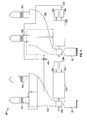
FIG. 2 is a schematic embodiment of an embodiment of a fluid cooled engine system; -
FIG. 3 is a schematic of coolant flow in a fluid cooled engine system; -
FIG. 4 is another schematic of coolant flow in a fluid cooled engine system; -
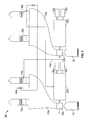
FIG. 5 is a schematic of lubricant flow in a fluid cooled engine system; -
FIG. 6 is another schematic of lubricant flow in a fluid cooled engine system; and -
FIG. 7 is a schematic of fluid flow in a fluid cooled engine system. - The detailed description explains embodiments of the invention, together with advantages and features, by way of example with reference to the drawings.
-
FIG. 1 is a schematic illustration of arotary wing aircraft 10 having amain rotor assembly 12. Theaircraft 10 includes anairframe 14 having an extendingtail 16 at which is mounted atail rotor 18. Themain rotor assembly 12 is driven by two or more fluid cooledengines 20 connected to the main rotor assembly via agearbox 22. - Referring now to
FIG. 2 , in some embodiments theaircraft 10 has twoengines 20, identified as 20a and 20b in the FIG. and is cooled via acooling system 24. It is to be appreciated that while thesystem 24 described herein is for cooling twoengines system 24 may be arranged to cool any number ofengines 20. Further, while thesystem 24 is described herein as applied to arotary wing aircraft 10, it may be applied to any use of a fluid cooledengine arrangement 20. Also, while thesystem 24 described herein is utilized to cool engines, it is to be appreciated that thesystem 24 may be utilized to cool other heat generating components or machines. - A
first engine 20a is operably connected to afirst fan 26a which urges a flow ofinlet air 28 into afirst duct 30a. A firstcoolant heat exchanger 32a and first engineoil heat exchanger 34a are arranged at thefirst duct 30a upstream of afirst duct outlet 36a. Further,first engine 20a is operably connected to afirst coolant pump 38a and afirst oil pump 40a. - Similarly, a
second engine 20b is operably connected to asecond fan 26b which urges a flow ofinlet air 28 into asecond duct 30b. A secondcoolant heat exchanger 32b and second engineoil heat exchanger 34b are arranged at thesecond duct 30b upstream of asecond duct outlet 36b. Further,second engine 20b is operably connected to asecond coolant pump 38b and asecond oil pump 40b. - Flow of coolant and engine oil for
engines engines cooling system 24 is illustrated inFIGs. 3-6 . Referring toFIG. 3 , when thefirst engine 20a is operating, thefirst fan 26a, thefirst coolant pump 38a and thefirst oil pump 40a, driven by thefirst engine 20a are also operating. Thefirst fan 26a urgesinlet air 28 through thefirst duct 30a and across the firstcoolant heat exchanger 32a and the first engineoil heat exchanger 34a. Thefirst coolant pump 38a pumps a firstengine coolant flow 42a from thefirst engine 20a. Thefirst coolant pump 38a urges this firstengine coolant flow 42a through the firstcoolant heat exchanger 32a, where thermal energy is transferred from the firstengine coolant flow 42a to theinlet air 28 flowing through thefirst duct 30a. The firstengine coolant flow 42a is then urged to the secondcoolant heat exchanger 32b and flowed therethrough to transfer thermal energy from the firstengine coolant flow 42a toinlet air 28 flowing through thesecond duct 30b. After flowing through the secondcoolant heat exchanger 32b, the firstengine coolant flow 42a is flowed into thefirst engine 20a where thermal energy is transferred from thefirst engine 20a to the firstengine coolant flow 42a to cool thefirst engine 20a. Directing the firstengine coolant flow 42a through both the firstcoolant heat exchanger 32a and the secondcoolant heat exchanger 32b allows for effective cooling of thefirst engine 20a even with failure of components such as the firstcoolant heat exchanger 32a, thefirst fan 26a orfirst duct 30a. - Similarly, and referring now to
FIG. 4 , a secondengine coolant flow 42b is pumped from thesecond engine 20b by thesecond coolant pump 38b. Thesecond coolant pump 38b urges the secondengine coolant flow 42b through the secondcoolant heat exchanger 32b, where thermal energy is transferred from the secondengine coolant flow 42b to theinlet air 28 flowing through thesecond duct 30b. The secondengine coolant flow 42b is then urged to the firstcoolant heat exchanger 32a and flowed therethrough to transfer thermal energy from the secondengine coolant flow 42b toinlet air 28 flowing through thefirst duct 30a. After flowing through the firstcoolant heat exchanger 32a, the secondengine coolant flow 42b is flowed into thesecond engine 20b where thermal energy is transferred from thesecond engine 20b to the secondengine coolant flow 42b to cool thesecond engine 20b. Directing the secondengine coolant flow 42b through both the secondcoolant heat exchanger 32b and the first enginecoolant heat exchanger 32a allows for effective cooling of thesecond engine 20b even with failure of components such as the secondcoolant heat exchanger 32b, thesecond fan 26b orsecond duct 30b. - Referring to
FIG. 5 , thefirst oil pump 40a pumps a firstengine oil flow 44a from thefirst engine 20a and through the first engineoil heat exchanger 34a, where thermal energy is transferred between the firstengine oil flow 44a and theinlet flow 28 through thefirst duct 30a. The firstengine oil flow 44a then proceeds through the second engineoil heat exchanger 34b and thermal energy is transferred between the firstengine oil flow 44a and theinlet flow 28 through thesecond duct 30b. The firstengine oil flow 44a is then flowed into thefirst engine 20a to lubricate and transfer thermal energy from thefirst engine 20a to the firstengine oil flow 44a to cool thefirst engine 20a. Directing the firstengine oil flow 44a through both the first engineoil heat exchanger 34a and the second engineoil heat exchanger 34b allows for effective cooling of the firstengine oil flow 44a even with failure of components such as the first engineoil heat exchanger 34a, thefirst fan 26a or thefirst duct 30a. - Referring to
FIG. 6 , thesecond oil pump 40b pumps a secondengine oil flow 44b from thesecond engine 20b and through the second engineoil heat exchanger 34b, where thermal energy is transferred between the secondengine oil flow 44b and theinlet flow 28 through thesecond duct 30b. The secondengine oil flow 44b then proceeds through the first engineoil heat exchanger 34a and thermal energy is transferred between the secondengine oil flow 44b and theinlet flow 28 through thefirst duct 30a. The secondengine oil flow 44b is then flowed into thesecond engine 20b to lubricate and transfer thermal energy from thesecond engine 20b to the secondengine oil flow 44b to cool thesecond engine 20b. Directing the secondengine oil flow 44b through both the second engineoil heat exchanger 34b and the first engineoil heat exchanger 34a allows for effective cooling of the secondengine oil flow 44b even with failure of components such as the second engineoil heat exchanger 34b, thesecond fan 26b or thesecond duct 30b. - Referring now to
FIG. 7 , thesystem 24 is still operable to serve a remaining engine in the case of failure of one engine. For example, as shown inFIG. 7 , in the case of a failure of thesecond engine 20b, thesystem 24 would still serve thefirst engine 20a with sufficient cooling capacity for continued normal operation. In the case of failure of thesecond engine 20b, firstengine coolant flow 42a is not routed to secondcoolant heat exchanger 32b, but is diverted back through firstcoolant heat exchanger 32a for a second pass by operation offirst coolant valve 46a. Similarly, the firstengine oil flow 44a is not routed to secondoil heat exchanger 34b, but is diverted for a second pass through firstoil heat exchanger 34a byfirst oil valve 48a.Second coolant valve 46b andsecond oil valve 48b (shown inFIG. 2 ) are provided to similarly divert the secondengine coolant flow 42b and the secondengine oil flow 44b in the case of a failure of thefirst engine 20a. In some embodiments, sensors such astemperature sensors 50 and/orpressure sensors 52 are provided in thesystem 24 to assist in determining functionality of thesystem 24. In some embodiments, the sensors are connected to ahealth monitor 54 or other controller that utilizes inputs from the sensors to determine ifvalves flows - While the invention has been described in detail in connection with only a limited number of embodiments, it should be readily understood that the invention is not limited to such disclosed embodiments. Rather, the invention can be modified to incorporate any number of variations, alterations, substitutions or equivalent arrangements not heretofore described, but which are commensurate with the spirit and scope of the invention. Additionally, while various embodiments of the invention have been described, it is to be understood that aspects of the invention may include only some of the described embodiments. Accordingly, the invention is not to be seen as limited by the foregoing description, but is only limited by the scope of the appended claims.
Claims (15)
- A fluid cooled system comprising:a first heat generating component (20a);a first airflow pathway (30a) to direct a first flow of air across a first heat exchanger (34a); anda second airflow pathway (30b) to direct a second flow of air across a second heat exchanger (34b);wherein a first working fluid is flowed from the first heat generating component (20a), through the first heat exchanger (34a) and through the second heat exchanger (34b) and returned to the first heat generating component (20b).
- The system of Claim 1, further comprising a second heat generating component (20b);
wherein a second working fluid is flowed from the second heat generating component (20b), through the second heat exchanger (34b) and through the first heat exchanger (34a) and returned to the second heat generating component (20b). - The system of Claim 1 or 2, wherein the first working fluid and the second working fluid are one of coolant or lubricant.
- The system of any of Claims 1 to 3, further comprising a first pump (38a; 40a) to urge the first working fluid through the first heat exchanger (34a).
- The system of any of Claims 1 to 4, further comprising a fan (26a) to urge the first flow of air through the first airflow pathway (30a).
- The system of Claim 5, wherein the fan (26a) is driven by the first heat generating component (20a).
- The cooling system of any of Claims 1 to 6, wherein the first airflow pathway is a first duct.
- A rotorcraft (10) comprising:an airframe (14);a rotor assembly (12, 18) operably connected to the airframe (14); anda fluid cooled system according to any of the previous claims;said fluid cooled system being a fluid cooled engine system operably connected to the rotor assembly (12, 18) with said first heat generating component comprising a first engine (20a).
- The rotorcraft (10) of Claim 8, with said second heat generating component comprising a second engine.
- A method of operating a fluid cooled engine system comprising:urging a first working fluid from a first engine (20a);urging the first working fluid through a first heat exchanger (34a);urging a first airflow across the first heat exchanger (34a) via a first airflow pathway (30a) thereby transferring thermal energy between the first working fluid and the first airflow;conveying the first working fluid across a second heat exchanger (34b);urging a second airflow across the second heat exchanger (34b) via a second airflow pathway (30b) thereby transferring thermal energy between the first working fluid and the second airflow; andreturning the first working fluid to the first engine (20a).
- The method of Claim 11, further comprising:flowing a second working fluid from a second engine (24b) through the second heat exchanger (34b) thereby transferring thermal energy between the second working fluid and the second airflow;conveying the second working fluid through the first heat exchanger (34a) thereby transferring thermal energy between the second working fluid and the first airflow; andreturning the second working fluid to the second engine (20b).
- The method of Claim 10 or 11, wherein the first working fluid and the second working fluid are one of coolant or lubricant.
- The method of any of Claims 10 to 12, further comprising:sensing a failure in the second heat exchanger (34b) of the second airflow pathway (30b);diverting the first working fluid through the first heat exchanger (34a) a second time to transfer additional thermal energy from the first working fluid; and returning the first working fluid to the first engine (20a).
- The method of any of Claims 10 to 13, further comprising:sensing a loss of sufficient airflow through the second airflow pathway (30b) to the second heat exchanger (34b);diverting the first working fluid through the first heat exchanger (34a) a second time to transfer additional thermal energy from the first working fluid; andreturning the first working fluid to the first engine (20a).
- The method of any of Claims 10 to 14, further comprising urging the first airflow through the first airflow pathway (30a) via a fan (26a), in particular comprising driving the fan (26a) with the first engine (20a).
Applications Claiming Priority (1)
| Application Number | Priority Date | Filing Date | Title |
|---|---|---|---|
| US13/645,795 US9435261B2 (en) | 2012-10-05 | 2012-10-05 | Redundant cooling for fluid cooled systems |
Publications (3)
| Publication Number | Publication Date |
|---|---|
| EP2716889A2 true EP2716889A2 (en) | 2014-04-09 |
| EP2716889A3 EP2716889A3 (en) | 2017-11-01 |
| EP2716889B1 EP2716889B1 (en) | 2019-07-31 |
Family
ID=49328365
Family Applications (1)
| Application Number | Title | Priority Date | Filing Date |
|---|---|---|---|
| EP13187397.8A Not-in-force EP2716889B1 (en) | 2012-10-05 | 2013-10-04 | Redundant cooling for fluid cooled systems |
Country Status (2)
| Country | Link |
|---|---|
| US (1) | US9435261B2 (en) |
| EP (1) | EP2716889B1 (en) |
Cited By (1)
| Publication number | Priority date | Publication date | Assignee | Title |
|---|---|---|---|---|
| EP3299289A1 (en) * | 2016-09-23 | 2018-03-28 | Bell Helicopter Textron Inc. | Redundant cooling system |
Families Citing this family (2)
| Publication number | Priority date | Publication date | Assignee | Title |
|---|---|---|---|---|
| FR3011277B1 (en) * | 2013-09-30 | 2018-04-06 | Turbomeca | TURBOMACHINE ADAPTED TO OPERATE IN VIREUR MODE |
| US10527012B2 (en) | 2017-06-29 | 2020-01-07 | Pratt & Whitney Canada Corp. | Engine assembly with engine and cooler compartments |
Family Cites Families (19)
| Publication number | Priority date | Publication date | Assignee | Title |
|---|---|---|---|---|
| US1519812A (en) * | 1923-06-04 | 1924-12-16 | Schneider Heinrich | Locomotive driven by internal-combustion engine |
| US2452007A (en) * | 1945-10-12 | 1948-10-19 | Westinghouse Electric Corp | Thermostatic regulation for engine cooling |
| GB665526A (en) * | 1949-08-25 | 1952-01-23 | Fell Developments Ltd | Improvements in and relating to cooling systems for the engines of a multi-engined vehicle |
| US3765168A (en) | 1972-08-24 | 1973-10-16 | Gen Motors Corp | Water recovery |
| US3963372A (en) * | 1975-01-17 | 1976-06-15 | General Motors Corporation | Helicopter power plant control |
| US5253484A (en) | 1991-08-22 | 1993-10-19 | The Boeing Company | High reliability avionic cooling system |
| US5879466A (en) * | 1996-11-14 | 1999-03-09 | Caterpillar Inc. | Apparatus and method for cleaning radiator fins |
| FR2826094B1 (en) | 2001-06-15 | 2003-11-28 | Eurocopter France | LUBRICATION AND COOLING SYSTEM FOR A MECHANICAL ASSEMBLY |
| US6695591B2 (en) * | 2002-05-20 | 2004-02-24 | Grimmer Industries, Inc. | Multi-stage gas compressor system |
| DE10243775B4 (en) | 2002-09-20 | 2004-09-30 | Siemens Ag | Redundant cooling device for an electric submarine drive motor |
| US7259469B2 (en) * | 2003-07-31 | 2007-08-21 | Scs Frigette Inc. | Vehicle auxiliary power unit, assembly, and related methods |
| CA2474415A1 (en) * | 2004-07-15 | 2006-01-15 | Gerald Hayes | Auxillary cooler for an engine located in a building |
| US7434765B2 (en) * | 2005-02-16 | 2008-10-14 | The Boeing Company | Heat exchanger systems and associated systems and methods for cooling aircraft starter/generators |
| US20100181416A1 (en) * | 2005-08-04 | 2010-07-22 | Yamaha Hatsudoki Kabushiki Kaisha | Unmanned helicopter |
| US8402929B2 (en) * | 2007-09-24 | 2013-03-26 | General Electric Company | Cooling system and method |
| EP2072763B1 (en) * | 2007-12-21 | 2015-04-08 | Techspace Aero S.A. | Heat exchange system in a turbomachine |
| KR101036624B1 (en) * | 2009-04-01 | 2011-05-24 | 원신 스카이텍 주식회사 | Unmanned helicopter engine cooling system |
| US9109464B2 (en) * | 2011-08-31 | 2015-08-18 | United Technologies Corporation | Distributed lubrication system |
| CN202417680U (en) * | 2011-11-29 | 2012-09-05 | 成都精石模型开发有限公司 | Radiator for unmanned helicopter |
-
2012
- 2012-10-05 US US13/645,795 patent/US9435261B2/en active Active
-
2013
- 2013-10-04 EP EP13187397.8A patent/EP2716889B1/en not_active Not-in-force
Non-Patent Citations (1)
| Title |
|---|
| None |
Cited By (2)
| Publication number | Priority date | Publication date | Assignee | Title |
|---|---|---|---|---|
| EP3299289A1 (en) * | 2016-09-23 | 2018-03-28 | Bell Helicopter Textron Inc. | Redundant cooling system |
| US10907723B2 (en) | 2016-09-23 | 2021-02-02 | Bell Helicopter Textron Inc. | Redundant cooling system |
Also Published As
| Publication number | Publication date |
|---|---|
| US9435261B2 (en) | 2016-09-06 |
| EP2716889A3 (en) | 2017-11-01 |
| US20140096525A1 (en) | 2014-04-10 |
| EP2716889B1 (en) | 2019-07-31 |
Similar Documents
| Publication | Publication Date | Title |
|---|---|---|
| CN112814786B (en) | Thermal management system with thermal bus for gas turbine engines or aircraft | |
| EP3124770B1 (en) | Thermal management system of a gas turbine | |
| EP2587024B1 (en) | Gas turbine engine thermal management system | |
| US8205427B2 (en) | Interdependent lubrication systems in a turbine engine | |
| EP2954185B1 (en) | Multi-circuit lubrication system for a turbine engine | |
| EP2696055B1 (en) | Gas turbine engine heat exchangers | |
| EP2954212B1 (en) | Multi-circuit lubrication system for a turbine engine | |
| US8297038B2 (en) | Gas turbine aircraft engines and operation thereof | |
| EP3070277B1 (en) | Air cycle machine with cooling air flow path | |
| EP2578845A2 (en) | An oil cooling system | |
| EP3144623B1 (en) | Heat exchanger and cooling system for generator electronics cooling | |
| CN106907192A (en) | thermal management system | |
| JP2014034975A (en) | Gas turbine heat exchanger operating method and device | |
| US12305522B2 (en) | Turbomachine lubrication system comprising a bypass for preferentially supplying lubricant to a low-speed reduction gear | |
| JP5897602B2 (en) | Method and apparatus for supplying lubricant | |
| US9435261B2 (en) | Redundant cooling for fluid cooled systems | |
| CN114837815A (en) | High temperature fuel heat transfer bus architecture | |
| EP3608617A1 (en) | Heat exchanger for an aircraft | |
| EP3045697A1 (en) | Cooling air supply control system for air cycle machine | |
| CN115380156B (en) | Isolation of turbine engine heat exchangers in the event of leakage of electrical and mechanical hydraulic control valves | |
| EP4299444A1 (en) | Split regeneration environmental control system | |
| EP2971646B1 (en) | Gas turbine engine thermal management system |
Legal Events
| Date | Code | Title | Description |
|---|---|---|---|
| PUAI | Public reference made under article 153(3) epc to a published international application that has entered the european phase |
Free format text: ORIGINAL CODE: 0009012 |
|
| AK | Designated contracting states |
Kind code of ref document: A2 Designated state(s): AL AT BE BG CH CY CZ DE DK EE ES FI FR GB GR HR HU IE IS IT LI LT LU LV MC MK MT NL NO PL PT RO RS SE SI SK SM TR |
|
| AX | Request for extension of the european patent |
Extension state: BA ME |
|
| PUAL | Search report despatched |
Free format text: ORIGINAL CODE: 0009013 |
|
| AK | Designated contracting states |
Kind code of ref document: A3 Designated state(s): AL AT BE BG CH CY CZ DE DK EE ES FI FR GB GR HR HU IE IS IT LI LT LU LV MC MK MT NL NO PL PT RO RS SE SI SK SM TR |
|
| AX | Request for extension of the european patent |
Extension state: BA ME |
|
| RIC1 | Information provided on ipc code assigned before grant |
Ipc: F02C 7/14 20060101AFI20170925BHEP |
|
| 17P | Request for examination filed |
Effective date: 20180430 |
|
| RBV | Designated contracting states (corrected) |
Designated state(s): AL AT BE BG CH CY CZ DE DK EE ES FI FR GB GR HR HU IE IS IT LI LT LU LV MC MK MT NL NO PL PT RO RS SE SI SK SM TR |
|
| GRAP | Despatch of communication of intention to grant a patent |
Free format text: ORIGINAL CODE: EPIDOSNIGR1 |
|
| STAA | Information on the status of an ep patent application or granted ep patent |
Free format text: STATUS: GRANT OF PATENT IS INTENDED |
|
| INTG | Intention to grant announced |
Effective date: 20190211 |
|
| GRAS | Grant fee paid |
Free format text: ORIGINAL CODE: EPIDOSNIGR3 |
|
| GRAA | (expected) grant |
Free format text: ORIGINAL CODE: 0009210 |
|
| STAA | Information on the status of an ep patent application or granted ep patent |
Free format text: STATUS: THE PATENT HAS BEEN GRANTED |
|
| AK | Designated contracting states |
Kind code of ref document: B1 Designated state(s): AL AT BE BG CH CY CZ DE DK EE ES FI FR GB GR HR HU IE IS IT LI LT LU LV MC MK MT NL NO PL PT RO RS SE SI SK SM TR |
|
| REG | Reference to a national code |
Ref country code: CH Ref legal event code: EP Ref country code: GB Ref legal event code: FG4D |
|
| REG | Reference to a national code |
Ref country code: AT Ref legal event code: REF Ref document number: 1161143 Country of ref document: AT Kind code of ref document: T Effective date: 20190815 |
|
| REG | Reference to a national code |
Ref country code: IE Ref legal event code: FG4D |
|
| REG | Reference to a national code |
Ref country code: DE Ref legal event code: R096 Ref document number: 602013058428 Country of ref document: DE |
|
| REG | Reference to a national code |
Ref country code: NL Ref legal event code: MP Effective date: 20190731 |
|
| REG | Reference to a national code |
Ref country code: LT Ref legal event code: MG4D |
|
| REG | Reference to a national code |
Ref country code: AT Ref legal event code: MK05 Ref document number: 1161143 Country of ref document: AT Kind code of ref document: T Effective date: 20190731 |
|
| PG25 | Lapsed in a contracting state [announced via postgrant information from national office to epo] |
Ref country code: FI Free format text: LAPSE BECAUSE OF FAILURE TO SUBMIT A TRANSLATION OF THE DESCRIPTION OR TO PAY THE FEE WITHIN THE PRESCRIBED TIME-LIMIT Effective date: 20190731 Ref country code: LT Free format text: LAPSE BECAUSE OF FAILURE TO SUBMIT A TRANSLATION OF THE DESCRIPTION OR TO PAY THE FEE WITHIN THE PRESCRIBED TIME-LIMIT Effective date: 20190731 Ref country code: NL Free format text: LAPSE BECAUSE OF FAILURE TO SUBMIT A TRANSLATION OF THE DESCRIPTION OR TO PAY THE FEE WITHIN THE PRESCRIBED TIME-LIMIT Effective date: 20190731 Ref country code: BG Free format text: LAPSE BECAUSE OF FAILURE TO SUBMIT A TRANSLATION OF THE DESCRIPTION OR TO PAY THE FEE WITHIN THE PRESCRIBED TIME-LIMIT Effective date: 20191031 Ref country code: AT Free format text: LAPSE BECAUSE OF FAILURE TO SUBMIT A TRANSLATION OF THE DESCRIPTION OR TO PAY THE FEE WITHIN THE PRESCRIBED TIME-LIMIT Effective date: 20190731 Ref country code: PT Free format text: LAPSE BECAUSE OF FAILURE TO SUBMIT A TRANSLATION OF THE DESCRIPTION OR TO PAY THE FEE WITHIN THE PRESCRIBED TIME-LIMIT Effective date: 20191202 Ref country code: NO Free format text: LAPSE BECAUSE OF FAILURE TO SUBMIT A TRANSLATION OF THE DESCRIPTION OR TO PAY THE FEE WITHIN THE PRESCRIBED TIME-LIMIT Effective date: 20191031 Ref country code: HR Free format text: LAPSE BECAUSE OF FAILURE TO SUBMIT A TRANSLATION OF THE DESCRIPTION OR TO PAY THE FEE WITHIN THE PRESCRIBED TIME-LIMIT Effective date: 20190731 Ref country code: SE Free format text: LAPSE BECAUSE OF FAILURE TO SUBMIT A TRANSLATION OF THE DESCRIPTION OR TO PAY THE FEE WITHIN THE PRESCRIBED TIME-LIMIT Effective date: 20190731 |
|
| PGFP | Annual fee paid to national office [announced via postgrant information from national office to epo] |
Ref country code: DE Payment date: 20191029 Year of fee payment: 7 |
|
| PG25 | Lapsed in a contracting state [announced via postgrant information from national office to epo] |
Ref country code: IS Free format text: LAPSE BECAUSE OF FAILURE TO SUBMIT A TRANSLATION OF THE DESCRIPTION OR TO PAY THE FEE WITHIN THE PRESCRIBED TIME-LIMIT Effective date: 20191130 Ref country code: RS Free format text: LAPSE BECAUSE OF FAILURE TO SUBMIT A TRANSLATION OF THE DESCRIPTION OR TO PAY THE FEE WITHIN THE PRESCRIBED TIME-LIMIT Effective date: 20190731 Ref country code: GR Free format text: LAPSE BECAUSE OF FAILURE TO SUBMIT A TRANSLATION OF THE DESCRIPTION OR TO PAY THE FEE WITHIN THE PRESCRIBED TIME-LIMIT Effective date: 20191101 Ref country code: AL Free format text: LAPSE BECAUSE OF FAILURE TO SUBMIT A TRANSLATION OF THE DESCRIPTION OR TO PAY THE FEE WITHIN THE PRESCRIBED TIME-LIMIT Effective date: 20190731 Ref country code: ES Free format text: LAPSE BECAUSE OF FAILURE TO SUBMIT A TRANSLATION OF THE DESCRIPTION OR TO PAY THE FEE WITHIN THE PRESCRIBED TIME-LIMIT Effective date: 20190731 Ref country code: LV Free format text: LAPSE BECAUSE OF FAILURE TO SUBMIT A TRANSLATION OF THE DESCRIPTION OR TO PAY THE FEE WITHIN THE PRESCRIBED TIME-LIMIT Effective date: 20190731 |
|
| PGFP | Annual fee paid to national office [announced via postgrant information from national office to epo] |
Ref country code: FR Payment date: 20191025 Year of fee payment: 7 |
|
| PG25 | Lapsed in a contracting state [announced via postgrant information from national office to epo] |
Ref country code: TR Free format text: LAPSE BECAUSE OF FAILURE TO SUBMIT A TRANSLATION OF THE DESCRIPTION OR TO PAY THE FEE WITHIN THE PRESCRIBED TIME-LIMIT Effective date: 20190731 |
|
| PG25 | Lapsed in a contracting state [announced via postgrant information from national office to epo] |
Ref country code: EE Free format text: LAPSE BECAUSE OF FAILURE TO SUBMIT A TRANSLATION OF THE DESCRIPTION OR TO PAY THE FEE WITHIN THE PRESCRIBED TIME-LIMIT Effective date: 20190731 Ref country code: PL Free format text: LAPSE BECAUSE OF FAILURE TO SUBMIT A TRANSLATION OF THE DESCRIPTION OR TO PAY THE FEE WITHIN THE PRESCRIBED TIME-LIMIT Effective date: 20190731 Ref country code: DK Free format text: LAPSE BECAUSE OF FAILURE TO SUBMIT A TRANSLATION OF THE DESCRIPTION OR TO PAY THE FEE WITHIN THE PRESCRIBED TIME-LIMIT Effective date: 20190731 Ref country code: IT Free format text: LAPSE BECAUSE OF FAILURE TO SUBMIT A TRANSLATION OF THE DESCRIPTION OR TO PAY THE FEE WITHIN THE PRESCRIBED TIME-LIMIT Effective date: 20190731 Ref country code: RO Free format text: LAPSE BECAUSE OF FAILURE TO SUBMIT A TRANSLATION OF THE DESCRIPTION OR TO PAY THE FEE WITHIN THE PRESCRIBED TIME-LIMIT Effective date: 20190731 |
|
| PGFP | Annual fee paid to national office [announced via postgrant information from national office to epo] |
Ref country code: GB Payment date: 20191028 Year of fee payment: 7 |
|
| PG25 | Lapsed in a contracting state [announced via postgrant information from national office to epo] |
Ref country code: SK Free format text: LAPSE BECAUSE OF FAILURE TO SUBMIT A TRANSLATION OF THE DESCRIPTION OR TO PAY THE FEE WITHIN THE PRESCRIBED TIME-LIMIT Effective date: 20190731 Ref country code: CZ Free format text: LAPSE BECAUSE OF FAILURE TO SUBMIT A TRANSLATION OF THE DESCRIPTION OR TO PAY THE FEE WITHIN THE PRESCRIBED TIME-LIMIT Effective date: 20190731 Ref country code: MC Free format text: LAPSE BECAUSE OF FAILURE TO SUBMIT A TRANSLATION OF THE DESCRIPTION OR TO PAY THE FEE WITHIN THE PRESCRIBED TIME-LIMIT Effective date: 20190731 Ref country code: IS Free format text: LAPSE BECAUSE OF FAILURE TO SUBMIT A TRANSLATION OF THE DESCRIPTION OR TO PAY THE FEE WITHIN THE PRESCRIBED TIME-LIMIT Effective date: 20200224 Ref country code: SM Free format text: LAPSE BECAUSE OF FAILURE TO SUBMIT A TRANSLATION OF THE DESCRIPTION OR TO PAY THE FEE WITHIN THE PRESCRIBED TIME-LIMIT Effective date: 20190731 |
|
| REG | Reference to a national code |
Ref country code: CH Ref legal event code: PL |
|
| REG | Reference to a national code |
Ref country code: DE Ref legal event code: R097 Ref document number: 602013058428 Country of ref document: DE |
|
| PLBE | No opposition filed within time limit |
Free format text: ORIGINAL CODE: 0009261 |
|
| STAA | Information on the status of an ep patent application or granted ep patent |
Free format text: STATUS: NO OPPOSITION FILED WITHIN TIME LIMIT |
|
| PG2D | Information on lapse in contracting state deleted |
Ref country code: IS |
|
| PG25 | Lapsed in a contracting state [announced via postgrant information from national office to epo] |
Ref country code: CH Free format text: LAPSE BECAUSE OF NON-PAYMENT OF DUE FEES Effective date: 20191031 Ref country code: LU Free format text: LAPSE BECAUSE OF NON-PAYMENT OF DUE FEES Effective date: 20191004 Ref country code: LI Free format text: LAPSE BECAUSE OF NON-PAYMENT OF DUE FEES Effective date: 20191031 Ref country code: IS Free format text: LAPSE BECAUSE OF FAILURE TO SUBMIT A TRANSLATION OF THE DESCRIPTION OR TO PAY THE FEE WITHIN THE PRESCRIBED TIME-LIMIT Effective date: 20191030 |
|
| 26N | No opposition filed |
Effective date: 20200603 |
|
| REG | Reference to a national code |
Ref country code: BE Ref legal event code: MM Effective date: 20191031 |
|
| PG25 | Lapsed in a contracting state [announced via postgrant information from national office to epo] |
Ref country code: BE Free format text: LAPSE BECAUSE OF NON-PAYMENT OF DUE FEES Effective date: 20191031 Ref country code: SI Free format text: LAPSE BECAUSE OF FAILURE TO SUBMIT A TRANSLATION OF THE DESCRIPTION OR TO PAY THE FEE WITHIN THE PRESCRIBED TIME-LIMIT Effective date: 20190731 |
|
| PG25 | Lapsed in a contracting state [announced via postgrant information from national office to epo] |
Ref country code: IE Free format text: LAPSE BECAUSE OF NON-PAYMENT OF DUE FEES Effective date: 20191004 |
|
| REG | Reference to a national code |
Ref country code: DE Ref legal event code: R119 Ref document number: 602013058428 Country of ref document: DE |
|
| PG25 | Lapsed in a contracting state [announced via postgrant information from national office to epo] |
Ref country code: CY Free format text: LAPSE BECAUSE OF FAILURE TO SUBMIT A TRANSLATION OF THE DESCRIPTION OR TO PAY THE FEE WITHIN THE PRESCRIBED TIME-LIMIT Effective date: 20190731 |
|
| GBPC | Gb: european patent ceased through non-payment of renewal fee |
Effective date: 20201004 |
|
| PG25 | Lapsed in a contracting state [announced via postgrant information from national office to epo] |
Ref country code: FR Free format text: LAPSE BECAUSE OF NON-PAYMENT OF DUE FEES Effective date: 20201031 Ref country code: DE Free format text: LAPSE BECAUSE OF NON-PAYMENT OF DUE FEES Effective date: 20210501 Ref country code: HU Free format text: LAPSE BECAUSE OF FAILURE TO SUBMIT A TRANSLATION OF THE DESCRIPTION OR TO PAY THE FEE WITHIN THE PRESCRIBED TIME-LIMIT; INVALID AB INITIO Effective date: 20131004 Ref country code: MT Free format text: LAPSE BECAUSE OF FAILURE TO SUBMIT A TRANSLATION OF THE DESCRIPTION OR TO PAY THE FEE WITHIN THE PRESCRIBED TIME-LIMIT Effective date: 20190731 |
|
| PG25 | Lapsed in a contracting state [announced via postgrant information from national office to epo] |
Ref country code: GB Free format text: LAPSE BECAUSE OF NON-PAYMENT OF DUE FEES Effective date: 20201004 |
|
| PG25 | Lapsed in a contracting state [announced via postgrant information from national office to epo] |
Ref country code: MK Free format text: LAPSE BECAUSE OF FAILURE TO SUBMIT A TRANSLATION OF THE DESCRIPTION OR TO PAY THE FEE WITHIN THE PRESCRIBED TIME-LIMIT Effective date: 20190731 |