EP2716879A1 - Turbine exhaust plume mitigation system - Google Patents
Turbine exhaust plume mitigation system Download PDFInfo
- Publication number
- EP2716879A1 EP2716879A1 EP13186850.7A EP13186850A EP2716879A1 EP 2716879 A1 EP2716879 A1 EP 2716879A1 EP 13186850 A EP13186850 A EP 13186850A EP 2716879 A1 EP2716879 A1 EP 2716879A1
- Authority
- EP
- European Patent Office
- Prior art keywords
- exhaust
- compressor
- conduit
- fluidly connected
- turbine
- Prior art date
- Legal status (The legal status is an assumption and is not a legal conclusion. Google has not performed a legal analysis and makes no representation as to the accuracy of the status listed.)
- Withdrawn
Links
- 230000000116 mitigating effect Effects 0.000 title claims abstract description 70
- 239000012530 fluid Substances 0.000 claims abstract description 45
- 230000001105 regulatory effect Effects 0.000 claims abstract description 12
- 239000000203 mixture Substances 0.000 claims description 9
- 238000007865 diluting Methods 0.000 claims description 6
- 238000002156 mixing Methods 0.000 claims description 5
- 230000004044 response Effects 0.000 claims description 5
- 238000011084 recovery Methods 0.000 claims description 4
- 238000013022 venting Methods 0.000 claims description 2
- 239000003570 air Substances 0.000 description 61
- 239000000446 fuel Substances 0.000 description 13
- 239000007789 gas Substances 0.000 description 12
- 238000002485 combustion reaction Methods 0.000 description 9
- MGWGWNFMUOTEHG-UHFFFAOYSA-N 4-(3,5-dimethylphenyl)-1,3-thiazol-2-amine Chemical compound CC1=CC(C)=CC(C=2N=C(N)SC=2)=C1 MGWGWNFMUOTEHG-UHFFFAOYSA-N 0.000 description 7
- JCXJVPUVTGWSNB-UHFFFAOYSA-N nitrogen dioxide Inorganic materials O=[N]=O JCXJVPUVTGWSNB-UHFFFAOYSA-N 0.000 description 7
- OKTJSMMVPCPJKN-UHFFFAOYSA-N Carbon Chemical compound [C] OKTJSMMVPCPJKN-UHFFFAOYSA-N 0.000 description 6
- 238000000034 method Methods 0.000 description 6
- 239000000779 smoke Substances 0.000 description 6
- 239000012080 ambient air Substances 0.000 description 5
- 238000013459 approach Methods 0.000 description 5
- 238000010790 dilution Methods 0.000 description 5
- 239000012895 dilution Substances 0.000 description 5
- 239000004215 Carbon black (E152) Substances 0.000 description 4
- 229910052799 carbon Inorganic materials 0.000 description 4
- 229930195733 hydrocarbon Natural products 0.000 description 4
- 150000002430 hydrocarbons Chemical class 0.000 description 4
- 239000002245 particle Substances 0.000 description 4
- 230000006266 hibernation Effects 0.000 description 3
- 230000000007 visual effect Effects 0.000 description 3
- 238000000889 atomisation Methods 0.000 description 2
- 238000010586 diagram Methods 0.000 description 2
- 238000009792 diffusion process Methods 0.000 description 2
- 230000000694 effects Effects 0.000 description 2
- 239000000295 fuel oil Substances 0.000 description 2
- 239000001257 hydrogen Substances 0.000 description 2
- 229910052739 hydrogen Inorganic materials 0.000 description 2
- 239000007788 liquid Substances 0.000 description 2
- 239000004071 soot Substances 0.000 description 2
- 239000000126 substance Substances 0.000 description 2
- 208000019901 Anxiety disease Diseases 0.000 description 1
- 230000036506 anxiety Effects 0.000 description 1
- 230000009286 beneficial effect Effects 0.000 description 1
- 238000013500 data storage Methods 0.000 description 1
- 238000000605 extraction Methods 0.000 description 1
- 230000006870 function Effects 0.000 description 1
- 238000004519 manufacturing process Methods 0.000 description 1
Images


Classifications
-
- F—MECHANICAL ENGINEERING; LIGHTING; HEATING; WEAPONS; BLASTING
- F01—MACHINES OR ENGINES IN GENERAL; ENGINE PLANTS IN GENERAL; STEAM ENGINES
- F01D—NON-POSITIVE DISPLACEMENT MACHINES OR ENGINES, e.g. STEAM TURBINES
- F01D25/00—Component parts, details, or accessories, not provided for in, or of interest apart from, other groups
- F01D25/30—Exhaust heads, chambers, or the like
- F01D25/305—Exhaust heads, chambers, or the like with fluid, e.g. liquid injection
-
- F—MECHANICAL ENGINEERING; LIGHTING; HEATING; WEAPONS; BLASTING
- F02—COMBUSTION ENGINES; HOT-GAS OR COMBUSTION-PRODUCT ENGINE PLANTS
- F02C—GAS-TURBINE PLANTS; AIR INTAKES FOR JET-PROPULSION PLANTS; CONTROLLING FUEL SUPPLY IN AIR-BREATHING JET-PROPULSION PLANTS
- F02C6/00—Plural gas-turbine plants; Combinations of gas-turbine plants with other apparatus; Adaptations of gas-turbine plants for special use
- F02C6/04—Gas-turbine plants providing heated or pressurised working fluid for other apparatus, e.g. without mechanical power output
- F02C6/06—Gas-turbine plants providing heated or pressurised working fluid for other apparatus, e.g. without mechanical power output providing compressed gas
- F02C6/08—Gas-turbine plants providing heated or pressurised working fluid for other apparatus, e.g. without mechanical power output providing compressed gas the gas being bled from the gas-turbine compressor
-
- F—MECHANICAL ENGINEERING; LIGHTING; HEATING; WEAPONS; BLASTING
- F02—COMBUSTION ENGINES; HOT-GAS OR COMBUSTION-PRODUCT ENGINE PLANTS
- F02K—JET-PROPULSION PLANTS
- F02K1/00—Plants characterised by the form or arrangement of the jet pipe or nozzle; Jet pipes or nozzles peculiar thereto
- F02K1/38—Introducing air inside the jet
-
- F—MECHANICAL ENGINEERING; LIGHTING; HEATING; WEAPONS; BLASTING
- F02—COMBUSTION ENGINES; HOT-GAS OR COMBUSTION-PRODUCT ENGINE PLANTS
- F02K—JET-PROPULSION PLANTS
- F02K1/00—Plants characterised by the form or arrangement of the jet pipe or nozzle; Jet pipes or nozzles peculiar thereto
- F02K1/78—Other construction of jet pipes
- F02K1/82—Jet pipe walls, e.g. liners
- F02K1/822—Heat insulating structures or liners, cooling arrangements, e.g. post combustion liners; Infrared radiation suppressors
-
- F—MECHANICAL ENGINEERING; LIGHTING; HEATING; WEAPONS; BLASTING
- F05—INDEXING SCHEMES RELATING TO ENGINES OR PUMPS IN VARIOUS SUBCLASSES OF CLASSES F01-F04
- F05D—INDEXING SCHEME FOR ASPECTS RELATING TO NON-POSITIVE-DISPLACEMENT MACHINES OR ENGINES, GAS-TURBINES OR JET-PROPULSION PLANTS
- F05D2270/00—Control
- F05D2270/01—Purpose of the control system
- F05D2270/08—Purpose of the control system to produce clean exhaust gases
- F05D2270/083—Purpose of the control system to produce clean exhaust gases by monitoring combustion conditions
- F05D2270/0831—Purpose of the control system to produce clean exhaust gases by monitoring combustion conditions indirectly, at the exhaust
-
- Y—GENERAL TAGGING OF NEW TECHNOLOGICAL DEVELOPMENTS; GENERAL TAGGING OF CROSS-SECTIONAL TECHNOLOGIES SPANNING OVER SEVERAL SECTIONS OF THE IPC; TECHNICAL SUBJECTS COVERED BY FORMER USPC CROSS-REFERENCE ART COLLECTIONS [XRACs] AND DIGESTS
- Y02—TECHNOLOGIES OR APPLICATIONS FOR MITIGATION OR ADAPTATION AGAINST CLIMATE CHANGE
- Y02T—CLIMATE CHANGE MITIGATION TECHNOLOGIES RELATED TO TRANSPORTATION
- Y02T50/00—Aeronautics or air transport
- Y02T50/60—Efficient propulsion technologies, e.g. for aircraft
Definitions
- the subject matter disclosed herein relates to power systems. More particularly, the subject matter relates to power system emissions.
- Incomplete combustion in power systems e.g., those including one or more gas turbines (GTs) can cause emission of (colored) nitrogen dioxide (NO 2 ) and unburned (colored) carbon-rich particles, due to the chemical composition of the gas or liquid hydrocarbon fuel being burned, the combustion temperature and/or the fuel-air ratio of combustion.
- GTs gas turbines
- NO 2 nitrogen dioxide
- unburned carbon-rich particles due to the chemical composition of the gas or liquid hydrocarbon fuel being burned, the combustion temperature and/or the fuel-air ratio of combustion.
- certain types of fuel are more susceptible than others to the production and emission of unburned carbon-rich particles and NO 2 .
- certain heavy residual-grade fuel oils with high asphaltene content and long carbon chains, encountered in particular geographic regions are known to create soot (unburned hydrocarbon) in diffusion flames.
- the tendency for a given fuel to generate colored (visually perceivable) plume (e.g., smoke) and particulate emissions can also be influenced by factors such as: high fuel viscosity, high flame ignition temperature, high fuel carbon-to-hydrogen ratio, fuel atomization efficiency time within the combustion zone, etc.
- colored exhaust plumes can be significant.
- colored exhaust plumes are visually perceivable for up to 30 minutes or longer, e.g., during the startup phase of portions of a gas turbine power system. These colored plumes can be undesirable, particularly in cases where the power system is located proximate a residential and/or commercial geographic region.
- the exhaust plume mitigation system includes: a first conduit fluidly connecting a compressor to an exhaust chamber of the turbine; a first control valve operably connected with the first conduit for regulating flow of compressor air through the first conduit; and a fluid inductor including: a first inlet fluidly connected with the first conduit; a second inlet fluidly connected with ambient; and an outlet fluidly connected with the exhaust chamber.
- a first aspect of the invention includes an exhaust plume mitigation system for a turbine, the system having: a first conduit fluidly connecting a compressor to an exhaust chamber of the turbine; a first control valve operably connected with the first conduit for regulating flow of compressor air through the first conduit; and a fluid inductor including: a first inlet fluidly connected with the first conduit; a second inlet fluidly connected with ambient; and an outlet fluidly connected with the exhaust chamber.
- a second aspect of the invention includes a system having: a compressor; a combustor fluidly connected with an exhaust of the compressor; a turbine fluidly connected with an exhaust of the combustor; an exhaust chamber fluidly connected with an exhaust of the turbine; and an exhaust plume mitigation system fluidly connected to the compressor and the exhaust chamber, the exhaust plume mitigation system including: a first conduit fluidly connecting the compressor to the exhaust chamber; and a fluid inductor including: a first inlet fluidly connected with the first conduit; a second inlet fluidly connected with ambient; and an outlet fluidly connected with the exhaust chamber, wherein the fluid inductor is sized to provide air from the ambient to the exhaust chamber to mix with the exhaust of the turbine.
- a third aspect of the invention includes a power system having: a compressor; a combustor fluidly connected with an exhaust of the compressor; a turbine fluidly connected with an exhaust of the combustor; an exhaust chamber fluidly connected with an exhaust of the turbine; and an exhaust plume mitigation system fluidly connected to the compressor and the exhaust chamber, the exhaust plume mitigation system for diverting a portion of compressed air from the compressor to the exhaust chamber for mixing with an exhaust of the turbine.
- the subject matter disclosed herein relates to power systems. More particularly, the subject matter relates to power system emissions.
- Incomplete combustion in power systems e.g., those including one or more gas turbines (GTs) can cause emission of (colored) nitrogen dioxide (NO 2 ) and unburned carbon-rich particles, due to the chemical properties of the gas and liquid hydrocarbon fuel being burned.
- GTs gas turbines
- NO 2 nitrogen dioxide
- unburned carbon-rich particles due to the chemical properties of the gas and liquid hydrocarbon fuel being burned.
- certain types of fuel at certain combustion temperatures and fuel-to-air ratios, are more susceptible than others to the emission of NO 2 and unburned carbon-rich particles.
- certain heavy residual-grade fuel oils with high asphaltene content and long carbon chains, encountered in particular geographic regions are known to create soot (unburned hydrocarbon) in diffusion flames.
- the tendency for a given fuel to generate plume and particulate emissions can also be influenced by factors such as: high fuel viscosity, high flame ignition temperature, high fuel carbon-to-hydrogen ratio, fuel atomization efficiency time within the combustion zone, etc.
- the visual nuisance of colored (smoke) plumes can be significant.
- these plumes are visually perceivable for up to 30 minutes or longer, e.g., during the startup phase of portions of a power system.
- These smoke plumes can be undesirable, particularly in cases where the power system (e.g., gas turbine power system) is located proximate a residential and/or commercial geographic region.
- the visually perceivable nature of the smoke plumes can cause anxiety among the population located proximate the power system.
- the conventional approach for mitigating colored smoke plumes in a gas turbine-based power system is to modify the fuel-to-air ratio, combustion temperature and operational speed of the turbine and/or compressor in order to reduce the amount of colored plume produced.
- These conventional approaches can require implementing of complex controls logic, and can ultimately result in reduced system efficiency and reduced hot gas-path component life from running the turbine and/or compressor at a reduced level for longer than desired.
- These approaches can also extend the duration of startup of the turbine and/or compressor.
- various embodiments of the invention include a system which uses at least one inductor to mix the turbine's exhaust (exhaust discharge) before it reaches the heat recovery steam generator (HRSG) section.
- the inductor combines ambient air and diverted compressor discharge air, and provides this combination to the turbine exhaust chamber before exhausting that air to the HRSG section.
- the inductor can effectively dilute the turbine's exhaust (via mixing) prior to its release to the atmosphere, thereby reducing the appearance of colored plume (smoke).
- an exhaust plume mitigation system for a turbine e.g., a gas turbine
- the exhaust plume mitigation system can include a first conduit fluidly connecting a compressor to an exhaust chamber of the turbine.
- the exhaust plume mitigation system can further include a first control valve operably connected with the first conduit, where the first control valve regulates flow of compressor air through the first conduit.
- the exhaust plume mitigation system can further include a fluid inductor which has: a first inlet fluidly connected with the first conduit, a second inlet fluidly connected with ambient (ambient, or external, air), and an outlet fluidly connected with the exhaust chamber.
- a second aspect of the invention includes a system having: a compressor, a combustor fluidly connected with an exhaust of the compressor, a turbine fluidly connected with an exhaust of the combustor, and an exhaust chamber fluidly connected with an exhaust of the turbine.
- the system further includes an exhaust plume mitigation system fluidly connected to the compressor and the exhaust chamber.
- the exhaust plume mitigation system can include: a first conduit fluidly connecting the compressor to the exhaust chamber, and a fluid inductor.
- the fluid inductor can include: a first inlet fluidly connected with the first conduit, a second inlet fluidly connected with ambient, and an outlet fluidly connected with the exhaust chamber.
- the fluid inductor can be sized to provide air from the ambient to the exhaust chamber to mix with the exhaust of the turbine.
- a third aspect of the invention includes a power system.
- the power system can include: a compressor, a combustor fluidly connected with an exhaust of the compressor, a turbine fluidly connected with an exhaust of the combustor, and an exhaust chamber fluidly connected with an exhaust of the turbine.
- the power system can further include an exhaust plume mitigation system fluidly connected to the compressor and the exhaust chamber, the exhaust plume mitigation system for diverting a portion of compressed air from the compressor (the discharge of the compressor) to the exhaust chamber for mixing with an exhaust of the turbine (e.g., the exhaust gases from the turbine).
- FIG. 1 shows a schematic depiction of a power system (or simply, system) 2 according to various embodiments of the invention.
- the system 2 can include a compressor 4.
- the compressor 4 can include a conventional compressor for a power system, e.g., a gas turbine power system, and can include a set of inlet guide vanes (IGVs) 6 designed to direct the flow of ambient air 8 (e.g., filtered ambient air) into an inlet 10 of the compressor 4. This ambient air 8 enters the compressor 4, which compresses that air 8 for later use in a combustion cycle (described further herein).
- the compressor 4 can include a compressor discharge chamber (CDC) 12 fluidly connected with an exhaust 14 of the compressor 4.
- the CDC 12 can retain some of the compressed air from the compressor prior to providing that air to another component (e.g., a combustor 18 as described herein).
- the power system 2 can further include a combustor 18 fluidly connected with the exhaust 14 of the compressor 4. That is, the combustor 18 is fluidly connected (e.g., via a conduit 20 and/or the CDC 12) with the exhaust 14 of the compressor 4 such that fluid (e.g., compressed air) can flow between the compressor 4 and the combustor 18.
- the combustor 18 can utilize the compressed air received from the compressor 4 (via CDC 12 and/or conduit 20) to combust a fuel and produce a working fluid (e.g., a gas).
- the working fluid can then be provided to a turbine 22 which is fluidly connected (e.g., via another conduit 20) to an exhaust 24 of the combustor 18.
- the turbine 22 can utilize the energy of the working fluid to cause rotational motion of a shaft, e.g., a drive shaft (not shown), as is known in the art.
- the turbine 22, and in particular its exhaust 26, is fluidly connected (in some cases directly via joined casings) with an exhaust chamber 28.
- the working fluid may exit the exhaust 26 and enter the exhaust chamber 28.
- the exhaust chamber 28 (and the working fluid in that chamber 28) outlets to a reheater 30, such as a heat recovery steam generator (HRSG).
- HRSG heat recovery steam generator
- a working fluid e.g., through an outlet of the reheater
- colored emissions can be undesirable, as noted herein.
- power system 2 can further include an exhaust plume mitigation system 40 fluidly connected with the compressor 4 and the exhaust chamber 28.
- the exhaust plume mitigation system 40 is configured to monitor a parameter of the turbine 22 and provide dilution fluid to the exhaust chamber 28 based upon the parameter of the turbine 22.
- the exhaust plume mitigation system 40 can include a first conduit 41 fluidly connecting the compressor 4 to the exhaust chamber 28.
- the exhaust plume mitigation system 40 can also include a fluid inductor 42.
- the fluid inductor 42 is more clearly illustrated in the schematic depiction in FIG. 2 .
- the fluid inductor 42 is shown having a first inlet 44 fluidly connected with the first conduit 41, a second inlet 46 fluidly connected with ambient (e.g., ambient 8), and an outlet 48 fluidly connected with the exhaust chamber 28.
- the fluid inductor 42 can be sized to provide air from the ambient 8 to the exhaust chamber 28 to mix with (dilute) the exhaust of the turbine 22, e.g., before entering the reheater 30.
- the fluid inductor 42 can be configured to draw a vacuum across the second inlet 46 when fluid (e.g., diverted compressor 4 and/or CDC 12 fluid) is forced into the first inlet 44.
- the fluid inductor 42 can include a fluid nozzle 50 located proximate a fluid intersection 52 between the first inlet 44 and the second inlet 46.
- the fluid nozzle 50 can help to accelerate the flow of the diverted fluid from the compressor 4 and/or CDC 12 through the body 54 of the inductor 42 which in turn causes a vacuum effect across the second inlet 46.
- a low pressure zone is created in the fluid intersection 52, which draws higher pressure air from the ambient 8 into the second inlet 46.
- the air from ambient 8 can mix with the diverted fluid (from compressor 4 and/or CDC 12, entering via first conduit 41) to form a dilution mixture.
- This dilution mixture is then forced through a nozzle-diffuser region 56 downstream of the fluid nozzle 50.
- the nozzle-diffuser region 56 includes a diffuser 58 which opens to the outlet 48 of the inductor 42 (to the exhaust chamber 28).
- the exhaust plume mitigation system 40 can further include a first control valve 60 operably connected with the first conduit 41 for regulating flow of compressor 4 air through the first conduit 41.
- the exhaust plume mitigation system 40 can include a second conduit 61 fluidly connected with the first conduit 41 and the CDC 12, where the second conduit 61 can provide air from the CDC 12 to the first conduit 41 (e.g., at junction 63).
- the exhaust plume mitigation system 40 can further include a second control valve 64 operably connected with the second conduit 61, where the second control valve 64 is for regulating flow of the compressor discharge air (from the CDC 12) to the first conduit 41.
- the exhaust plume mitigation system 40 can also include a third control valve 66 which can control an amount of air extracted from the compressor 4 and supplied to the first conduit 41. It is understood that in various embodiments, air is extracted from only one of the compressor 4 or the CDC 12, such that one of the second control valve 64 or the third control valve 66 remains closed while the other of those valves is open.
- the exhaust plume mitigation system 40 can include a flow sensor (FS) 70 operably connected with the first conduit 41, where the flow sensor 70 is for detecting a rate of flow of the compressor air (compressor discharge air from CDC 12 and/or extracted air from compressor 4) through the first conduit 41.
- the exhaust plume mitigation system 40 can include a block valve 72 operably connected with the first conduit 41, the block valve 72 substantially absolutely permitting or substantially absolutely prohibiting the flow of the compressor air (compressor discharge air from CDC 12 and/or extracted air from compressor 4) through the first conduit 41 (to the inductor 42).
- the block valve 72 can be configured to either completely open or completely close, thereby acting as a substantially absolute block on flow through the first conduit 41 to the inductor 42 when closed. As shown, the block valve 72 is located downstream (further along the left-to-right fluid flow path) of the control valves (first 60, second 62 and third 64). As described herein, the exhaust plume mitigation system 40 can include at least one valve (e.g., first control valve 60, second control valve 62, third control valve 64 and/or block valve 72) for regulating flow of the portion of the compressed air (compressor discharge air from CDC 12 and/or extracted air from compressor 4) from the compressor 4 (and/or the CDC 12) to the exhaust chamber 28.
- first control valve 60, second control valve 62, third control valve 64 and/or block valve 72 for regulating flow of the portion of the compressed air (compressor discharge air from CDC 12 and/or extracted air from compressor 4) from the compressor 4 (and/or the CDC 12) to the exhaust chamber 28.
- the exhaust plume mitigation system 40 can further include a control system 74, which can be operably connected to various other components of the system 40 shown and described herein. That is, the control system 74 can include conventional control system components which are known in the art to be operably connected to the compressor 4, CDC 12, combustor 18, turbine 22, exhaust chamber 28 and/or reheater 30 (data connections shown in phantom, and connection to these components illustrated in phantom box above control system 74 for illustrative purposes). In various embodiments of the invention, the control system 74 is connected to one or more of the aforementioned components via wireless and/or hardwired means, e.g., including connections via sensors and/or other conventional power system electronics.
- wireless and/or hardwired means e.g., including connections via sensors and/or other conventional power system electronics.
- the control system 74 is further operably connected to the at least one valve (e.g., first control valve 60, second control valve 62, third control valve 64 and/or block valve 72) as well as the flow sensor 70.
- the control system 74 can control operation of one or more of the at least one valve (e.g., first control valve 60, second control valve 62, third control valve 64 and/or block valve 72) based upon a determined operating parameter of one of the components in the exhaust plume mitigation system 40.
- the exhaust plume mitigation system 40 can include a set (e.g., a pair) of systems described herein. That is, FIG. 1 has been described with reference to a single inductor 42 and associated components (e.g., conduit 41, flow sensor 70, etc.), however, as illustrated in that Figure, the exhaust plume mitigation system 40 can include an additional set of components (only partially labeled) for diluting the exhaust from the turbine 22 in the exhaust chamber 28. Some of these components may be controlled by the control system 74 described herein, and/or another control system known in the art.
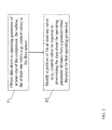
- control system 74 can perform processes according to the illustrative method flow diagram shown. That is, the control system 74 can perform the following functions to aid in diluting exhaust from the turbine 22 (e.g., to mitigate colored plume generation) according to the various embodiments of the invention:
- Process P1 obtain data about an operating parameter of one of the compressor 4, the turbine 22, the reheater (or, HRSG) 30, the at least one valve (e.g., first control valve 60, second control valve 62, third control valve 64 and/or block valve 74) or the flow sensor 70.
- the at least one valve e.g., first control valve 60, second control valve 62, third control valve 64 and/or block valve 74
- an operating parameter can include: a temperature of the HRSG 30, an opacity of the exhaust in the HRSG 30 stack, an exhaust gas temperature from the turbine 22, a discharge temperature of the compressor 4 or CDC 12 air, a flow rate of the compressor 4 and/or CDC 12 as compared with an emissions schedule, a position of the at least one valve (e.g., first control valve 60, second control valve 62, third control valve 64 and/or block valve 72), a flow rate through the first conduit 41 (as measured by flow sensor 70), a load on the turbine 22 (e.g., in mega-Watts), etc. It is understood that this data can be obtained by any conventional approaches such as by polling, logging, or periodically obtaining data from one or more sensors located throughout the exhaust plume mitigation system 40.
- a position of the at least one valve e.g., first control valve 60, second control valve 62, third control valve 64 and/or block valve 72
- a flow rate through the first conduit 41 as measured by flow sensor 70
- Process P2 Following obtaining of this data (about one or more of the herein-noted parameters), the control system 74 can compare this data with a predetermined threshold for the particular parameter(s), and modify a position of the at least one valve (e.g., first control valve 60, second control valve 62, third control valve 64 and/or block valve 72) in response to determining the data about the operating parameter deviates from the predetermined threshold for that operating parameter.
- a predetermined threshold for the particular parameter(s)
- control system 74 could determine that the compressor 4 and turbine 22 are undergoing a start-up (e.g., based upon a flow rate of the compressor 4 discharge and/or an output of the turbine 22), and open at least one valve (e.g., first control valve 60, second control valve 62, third control valve 64 and/or block valve 72) to permit extraction of air from the compressor 4 and/or the CDC 22, and introduction of that extracted air to the inductor 42.
- first control valve 60, second control valve 62, third control valve 64 and/or block valve 72 e.g., first control valve 60, second control valve 62, third control valve 64 and/or block valve 72
- the inductor draws in air from ambient 8, which can then be mixed with the exhaust from the turbine 22 in the exhaust chamber 28. Because the air from ambient 8 enhances exhaust dilution, the visual opacity of that exhaust leaving the HRSG 30 is subsequently reduced.
- control system could also monitor for a shut-down event (e.g., reduction in flow through the compressor 4 and/or reduced output in the turbine 22) and/or a hibernation event (e.g., steady-state reduced output in the turbine 22 and/or flow through the compressor 4) and subsequently modify a position of the at least one valve accordingly to engage the inductor 42 and mix with the exhaust from turbine 22.
- a shut-down event e.g., reduction in flow through the compressor 4 and/or reduced output in the turbine 22
- hibernation event e.g., steady-state reduced output in the turbine 22 and/or flow through the compressor
- the predetermined thresholds can include values for each of the parameters described herein which can indicate an event where it may be beneficial to engage the inductor 42 and dilute the exhaust from turbine 22.
- the predetermined threshold for turbine 22 output could be a mega-Watt level (e.g., below x mega-Watts indicates a shut-down, below y mega-Watts for z period indicates hibernation, increase of v percent in mega-Watt level over w period indicates a start-up).
- the control system 74 can compare the determined parameter(s) with these predetermined thresholds to determine whether an event of interest (e.g., startup, shutdown, hibernation, etc.) is occurring, and cause the exhaust plume mitigation system 40 to engage the inductor 42 accordingly.
- control system 74 can include conventional hardware components including one or more processors, memory, input/output devices and/or external data storage. In some cases, the control system 74 can be operated remotely, however, in some cases, the control system 74 can be operated on-site (e.g., proximate to the compressor 4, turbine 22, etc). In any case, the control system 74 has the technical effect of modifying the position of at least one valve to cause the flow of compressor (and/or CDC) air into the inductor 42, and consequently, into the exhaust chamber 28. This allows the control system to actuate dilution of the turbine 22 exhaust, thereby alleviating some of the issues associated with colored power system emissions described herein.
Landscapes
- Engineering & Computer Science (AREA)
- Mechanical Engineering (AREA)
- General Engineering & Computer Science (AREA)
- Chemical & Material Sciences (AREA)
- Combustion & Propulsion (AREA)
- Control Of Turbines (AREA)
- Engine Equipment That Uses Special Cycles (AREA)
Abstract
Description
- The subject matter disclosed herein relates to power systems. More particularly, the subject matter relates to power system emissions.
- Incomplete combustion in power systems, e.g., those including one or more gas turbines (GTs) can cause emission of (colored) nitrogen dioxide (NO2) and unburned (colored) carbon-rich particles, due to the chemical composition of the gas or liquid hydrocarbon fuel being burned, the combustion temperature and/or the fuel-air ratio of combustion. It has been discovered that certain types of fuel are more susceptible than others to the production and emission of unburned carbon-rich particles and NO2. For example, certain heavy residual-grade fuel oils with high asphaltene content and long carbon chains, encountered in particular geographic regions, are known to create soot (unburned hydrocarbon) in diffusion flames. However, the tendency for a given fuel to generate colored (visually perceivable) plume (e.g., smoke) and particulate emissions can also be influenced by factors such as: high fuel viscosity, high flame ignition temperature, high fuel carbon-to-hydrogen ratio, fuel atomization efficiency time within the combustion zone, etc.
- The visual nuisance of colored exhaust plumes (NO2 and particulate emissions) can be significant. In some cases, colored exhaust plumes are visually perceivable for up to 30 minutes or longer, e.g., during the startup phase of portions of a gas turbine power system. These colored plumes can be undesirable, particularly in cases where the power system is located proximate a residential and/or commercial geographic region.
- Various embodiments include an exhaust plume mitigation system for a turbine and systems incorporating the exhaust plume mitigation system. In some embodiments, the exhaust plume mitigation system includes: a first conduit fluidly connecting a compressor to an exhaust chamber of the turbine; a first control valve operably connected with the first conduit for regulating flow of compressor air through the first conduit; and a fluid inductor including: a first inlet fluidly connected with the first conduit; a second inlet fluidly connected with ambient; and an outlet fluidly connected with the exhaust chamber.
- A first aspect of the invention includes an exhaust plume mitigation system for a turbine, the system having: a first conduit fluidly connecting a compressor to an exhaust chamber of the turbine; a first control valve operably connected with the first conduit for regulating flow of compressor air through the first conduit; and a fluid inductor including: a first inlet fluidly connected with the first conduit; a second inlet fluidly connected with ambient; and an outlet fluidly connected with the exhaust chamber.
- A second aspect of the invention includes a system having: a compressor; a combustor fluidly connected with an exhaust of the compressor; a turbine fluidly connected with an exhaust of the combustor; an exhaust chamber fluidly connected with an exhaust of the turbine; and an exhaust plume mitigation system fluidly connected to the compressor and the exhaust chamber, the exhaust plume mitigation system including: a first conduit fluidly connecting the compressor to the exhaust chamber; and a fluid inductor including: a first inlet fluidly connected with the first conduit; a second inlet fluidly connected with ambient; and an outlet fluidly connected with the exhaust chamber, wherein the fluid inductor is sized to provide air from the ambient to the exhaust chamber to mix with the exhaust of the turbine.
- A third aspect of the invention includes a power system having: a compressor; a combustor fluidly connected with an exhaust of the compressor; a turbine fluidly connected with an exhaust of the combustor; an exhaust chamber fluidly connected with an exhaust of the turbine; and an exhaust plume mitigation system fluidly connected to the compressor and the exhaust chamber, the exhaust plume mitigation system for diverting a portion of compressed air from the compressor to the exhaust chamber for mixing with an exhaust of the turbine.
- These and other features of this invention will be more readily understood from the following detailed description of the various aspects of the invention taken in conjunction with the accompanying drawings that depict various embodiments of the invention, in which:
-
FIG. 1 shows a schematic depiction of a power system, including an exhaust plume mitigation system, according to various embodiments of the invention. -
FIG. 2 shows a schematic cross-sectional depiction of the fluid inductor of the exhaust plume mitigation system ofFIG. 1 . -
Fig. 3 shows a flow diagram illustrating process according to various embodiments of the invention. - It is noted that the drawings of the invention are not necessarily to scale. The drawings are intended to depict only typical aspects of the invention, and therefore should not be considered as limiting the scope of the invention. In the drawings, like numbering represents like elements between the drawings.
- As noted, the subject matter disclosed herein relates to power systems. More particularly, the subject matter relates to power system emissions.
- Incomplete combustion in power systems, e.g., those including one or more gas turbines (GTs) can cause emission of (colored) nitrogen dioxide (NO2) and unburned carbon-rich particles, due to the chemical properties of the gas and liquid hydrocarbon fuel being burned. It has been discovered that certain types of fuel, at certain combustion temperatures and fuel-to-air ratios, are more susceptible than others to the emission of NO2 and unburned carbon-rich particles. For example, certain heavy residual-grade fuel oils with high asphaltene content and long carbon chains, encountered in particular geographic regions, are known to create soot (unburned hydrocarbon) in diffusion flames. However, the tendency for a given fuel to generate plume and particulate emissions can also be influenced by factors such as: high fuel viscosity, high flame ignition temperature, high fuel carbon-to-hydrogen ratio, fuel atomization efficiency time within the combustion zone, etc.
- The visual nuisance of colored (smoke) plumes (particulate emissions) can be significant. In some cases, these plumes are visually perceivable for up to 30 minutes or longer, e.g., during the startup phase of portions of a power system. These smoke plumes can be undesirable, particularly in cases where the power system (e.g., gas turbine power system) is located proximate a residential and/or commercial geographic region. In particular, the visually perceivable nature of the smoke plumes can cause anxiety among the population located proximate the power system.
- The conventional approach for mitigating colored smoke plumes in a gas turbine-based power system is to modify the fuel-to-air ratio, combustion temperature and operational speed of the turbine and/or compressor in order to reduce the amount of colored plume produced. These conventional approaches can require implementing of complex controls logic, and can ultimately result in reduced system efficiency and reduced hot gas-path component life from running the turbine and/or compressor at a reduced level for longer than desired. These approaches can also extend the duration of startup of the turbine and/or compressor.
- In contrast to the conventional approaches, various embodiments of the invention include a system which uses at least one inductor to mix the turbine's exhaust (exhaust discharge) before it reaches the heat recovery steam generator (HRSG) section. The inductor combines ambient air and diverted compressor discharge air, and provides this combination to the turbine exhaust chamber before exhausting that air to the HRSG section. The inductor can effectively dilute the turbine's exhaust (via mixing) prior to its release to the atmosphere, thereby reducing the appearance of colored plume (smoke).
- In particular embodiments, an exhaust plume mitigation system for a turbine (e.g., a gas turbine) is disclosed. The exhaust plume mitigation system can include a first conduit fluidly connecting a compressor to an exhaust chamber of the turbine. The exhaust plume mitigation system can further include a first control valve operably connected with the first conduit, where the first control valve regulates flow of compressor air through the first conduit. The exhaust plume mitigation system can further include a fluid inductor which has: a first inlet fluidly connected with the first conduit, a second inlet fluidly connected with ambient (ambient, or external, air), and an outlet fluidly connected with the exhaust chamber.
- A second aspect of the invention includes a system having: a compressor, a combustor fluidly connected with an exhaust of the compressor, a turbine fluidly connected with an exhaust of the combustor, and an exhaust chamber fluidly connected with an exhaust of the turbine. The system further includes an exhaust plume mitigation system fluidly connected to the compressor and the exhaust chamber. The exhaust plume mitigation system can include: a first conduit fluidly connecting the compressor to the exhaust chamber, and a fluid inductor. The fluid inductor can include: a first inlet fluidly connected with the first conduit, a second inlet fluidly connected with ambient, and an outlet fluidly connected with the exhaust chamber. The fluid inductor can be sized to provide air from the ambient to the exhaust chamber to mix with the exhaust of the turbine.
- A third aspect of the invention includes a power system. The power system can include: a compressor, a combustor fluidly connected with an exhaust of the compressor, a turbine fluidly connected with an exhaust of the combustor, and an exhaust chamber fluidly connected with an exhaust of the turbine. The power system can further include an exhaust plume mitigation system fluidly connected to the compressor and the exhaust chamber, the exhaust plume mitigation system for diverting a portion of compressed air from the compressor (the discharge of the compressor) to the exhaust chamber for mixing with an exhaust of the turbine (e.g., the exhaust gases from the turbine).
-
FIG. 1 shows a schematic depiction of a power system (or simply, system) 2 according to various embodiments of the invention. As shown, thesystem 2 can include acompressor 4. As shown, thecompressor 4 can include a conventional compressor for a power system, e.g., a gas turbine power system, and can include a set of inlet guide vanes (IGVs) 6 designed to direct the flow of ambient air 8 (e.g., filtered ambient air) into aninlet 10 of thecompressor 4. Thisambient air 8 enters thecompressor 4, which compresses thatair 8 for later use in a combustion cycle (described further herein). In some cases, thecompressor 4 can include a compressor discharge chamber (CDC) 12 fluidly connected with anexhaust 14 of thecompressor 4. The CDC 12 can retain some of the compressed air from the compressor prior to providing that air to another component (e.g., acombustor 18 as described herein). - As shown, the
power system 2 can further include acombustor 18 fluidly connected with theexhaust 14 of thecompressor 4. That is, thecombustor 18 is fluidly connected (e.g., via aconduit 20 and/or the CDC 12) with theexhaust 14 of thecompressor 4 such that fluid (e.g., compressed air) can flow between thecompressor 4 and thecombustor 18. As is known in the art, thecombustor 18 can utilize the compressed air received from the compressor 4 (via CDC 12 and/or conduit 20) to combust a fuel and produce a working fluid (e.g., a gas). - The working fluid can then be provided to a
turbine 22 which is fluidly connected (e.g., via another conduit 20) to anexhaust 24 of thecombustor 18. Theturbine 22 can utilize the energy of the working fluid to cause rotational motion of a shaft, e.g., a drive shaft (not shown), as is known in the art. Theturbine 22, and in particular itsexhaust 26, is fluidly connected (in some cases directly via joined casings) with anexhaust chamber 28. The working fluid may exit theexhaust 26 and enter theexhaust chamber 28. In some cases, the exhaust chamber 28 (and the working fluid in that chamber 28) outlets to areheater 30, such as a heat recovery steam generator (HRSG). Following flow through thereheater 30, that working fluid enters the surrounding,ambient air 8 through anoutlet 32 of thereheater 30. As indicated herein, during startup and early-stage operation of a turbine system, the conventional systems outlet a working fluid (e.g., through an outlet of the reheater) which can include colored (e.g., black, yellow, etc.) emissions. These colored emissions can be undesirable, as noted herein. - In contrast to the conventional systems,
power system 2 can further include an exhaustplume mitigation system 40 fluidly connected with thecompressor 4 and theexhaust chamber 28. In various embodiments, the exhaustplume mitigation system 40 is configured to monitor a parameter of theturbine 22 and provide dilution fluid to theexhaust chamber 28 based upon the parameter of theturbine 22. - As shown, the exhaust
plume mitigation system 40 can include afirst conduit 41 fluidly connecting thecompressor 4 to theexhaust chamber 28. The exhaustplume mitigation system 40 can also include afluid inductor 42. Thefluid inductor 42 is more clearly illustrated in the schematic depiction inFIG. 2 . Turning to that Figure, and with continuing reference toFIG. 1 , thefluid inductor 42 is shown having afirst inlet 44 fluidly connected with thefirst conduit 41, asecond inlet 46 fluidly connected with ambient (e.g., ambient 8), and anoutlet 48 fluidly connected with theexhaust chamber 28. As described herein, thefluid inductor 42 can be sized to provide air from the ambient 8 to theexhaust chamber 28 to mix with (dilute) the exhaust of theturbine 22, e.g., before entering thereheater 30. - With continuing reference to
FIG. 2 , thefluid inductor 42 can be configured to draw a vacuum across thesecond inlet 46 when fluid (e.g., divertedcompressor 4 and/orCDC 12 fluid) is forced into thefirst inlet 44. In this case, as shown, thefluid inductor 42 can include afluid nozzle 50 located proximate afluid intersection 52 between thefirst inlet 44 and thesecond inlet 46. Thefluid nozzle 50 can help to accelerate the flow of the diverted fluid from thecompressor 4 and/orCDC 12 through thebody 54 of theinductor 42 which in turn causes a vacuum effect across thesecond inlet 46. That is, as the diverted fluid (fromcompressor 4 and/or CDC 12) is accelerated through thefluid nozzle 50 and thebody 54, a low pressure zone is created in thefluid intersection 52, which draws higher pressure air from the ambient 8 into thesecond inlet 46. Once inside thefluid inductor 42, the air from ambient 8 can mix with the diverted fluid (fromcompressor 4 and/orCDC 12, entering via first conduit 41) to form a dilution mixture. This dilution mixture is then forced through a nozzle-diffuser region 56 downstream of thefluid nozzle 50. The nozzle-diffuser region 56 includes adiffuser 58 which opens to theoutlet 48 of the inductor 42 (to the exhaust chamber 28). - Returning to
FIG. 1 , the exhaustplume mitigation system 40 can further include afirst control valve 60 operably connected with thefirst conduit 41 for regulating flow ofcompressor 4 air through thefirst conduit 41. Further, the exhaustplume mitigation system 40 can include asecond conduit 61 fluidly connected with thefirst conduit 41 and theCDC 12, where thesecond conduit 61 can provide air from theCDC 12 to the first conduit 41 (e.g., at junction 63). In this case, the exhaustplume mitigation system 40 can further include asecond control valve 64 operably connected with thesecond conduit 61, where thesecond control valve 64 is for regulating flow of the compressor discharge air (from the CDC 12) to thefirst conduit 41. Even further, the exhaustplume mitigation system 40 can also include athird control valve 66 which can control an amount of air extracted from thecompressor 4 and supplied to thefirst conduit 41. It is understood that in various embodiments, air is extracted from only one of thecompressor 4 or theCDC 12, such that one of thesecond control valve 64 or thethird control valve 66 remains closed while the other of those valves is open. - Also shown, the exhaust
plume mitigation system 40 can include a flow sensor (FS) 70 operably connected with thefirst conduit 41, where theflow sensor 70 is for detecting a rate of flow of the compressor air (compressor discharge air fromCDC 12 and/or extracted air from compressor 4) through thefirst conduit 41. Even further, the exhaustplume mitigation system 40 can include ablock valve 72 operably connected with thefirst conduit 41, theblock valve 72 substantially absolutely permitting or substantially absolutely prohibiting the flow of the compressor air (compressor discharge air fromCDC 12 and/or extracted air from compressor 4) through the first conduit 41 (to the inductor 42). As is known in the art, theblock valve 72 can be configured to either completely open or completely close, thereby acting as a substantially absolute block on flow through thefirst conduit 41 to theinductor 42 when closed. As shown, theblock valve 72 is located downstream (further along the left-to-right fluid flow path) of the control valves (first 60, second 62 and third 64). As described herein, the exhaustplume mitigation system 40 can include at least one valve (e.g.,first control valve 60, second control valve 62,third control valve 64 and/or block valve 72) for regulating flow of the portion of the compressed air (compressor discharge air fromCDC 12 and/or extracted air from compressor 4) from the compressor 4 (and/or the CDC 12) to theexhaust chamber 28. - Also shown in
FIG. 1 , the exhaustplume mitigation system 40 can further include acontrol system 74, which can be operably connected to various other components of thesystem 40 shown and described herein. That is, thecontrol system 74 can include conventional control system components which are known in the art to be operably connected to thecompressor 4,CDC 12,combustor 18,turbine 22,exhaust chamber 28 and/or reheater 30 (data connections shown in phantom, and connection to these components illustrated in phantom box abovecontrol system 74 for illustrative purposes). In various embodiments of the invention, thecontrol system 74 is connected to one or more of the aforementioned components via wireless and/or hardwired means, e.g., including connections via sensors and/or other conventional power system electronics. - The
control system 74 is further operably connected to the at least one valve (e.g.,first control valve 60, second control valve 62,third control valve 64 and/or block valve 72) as well as theflow sensor 70. In various embodiments, thecontrol system 74 can control operation of one or more of the at least one valve (e.g.,first control valve 60, second control valve 62,third control valve 64 and/or block valve 72) based upon a determined operating parameter of one of the components in the exhaustplume mitigation system 40. - It is understood that in various embodiments of the invention, the exhaust
plume mitigation system 40 can include a set (e.g., a pair) of systems described herein. That is,FIG. 1 has been described with reference to asingle inductor 42 and associated components (e.g.,conduit 41,flow sensor 70, etc.), however, as illustrated in that Figure, the exhaustplume mitigation system 40 can include an additional set of components (only partially labeled) for diluting the exhaust from theturbine 22 in theexhaust chamber 28. Some of these components may be controlled by thecontrol system 74 described herein, and/or another control system known in the art. - Turning to
FIG. 3 , in particular embodiments, thecontrol system 74 can perform processes according to the illustrative method flow diagram shown. That is, thecontrol system 74 can perform the following functions to aid in diluting exhaust from the turbine 22 (e.g., to mitigate colored plume generation) according to the various embodiments of the invention: - Process P1: obtain data about an operating parameter of one of the
compressor 4, theturbine 22, the reheater (or, HRSG) 30, the at least one valve (e.g.,first control valve 60, second control valve 62,third control valve 64 and/or block valve 74) or theflow sensor 70. In some cases, an operating parameter can include: a temperature of theHRSG 30, an opacity of the exhaust in theHRSG 30 stack, an exhaust gas temperature from theturbine 22, a discharge temperature of thecompressor 4 orCDC 12 air, a flow rate of thecompressor 4 and/orCDC 12 as compared with an emissions schedule, a position of the at least one valve (e.g.,first control valve 60, second control valve 62,third control valve 64 and/or block valve 72), a flow rate through the first conduit 41 (as measured by flow sensor 70), a load on the turbine 22 (e.g., in mega-Watts), etc. It is understood that this data can be obtained by any conventional approaches such as by polling, logging, or periodically obtaining data from one or more sensors located throughout the exhaustplume mitigation system 40. - Process P2: Following obtaining of this data (about one or more of the herein-noted parameters), the
control system 74 can compare this data with a predetermined threshold for the particular parameter(s), and modify a position of the at least one valve (e.g.,first control valve 60, second control valve 62,third control valve 64 and/or block valve 72) in response to determining the data about the operating parameter deviates from the predetermined threshold for that operating parameter. For example, in some cases, thecontrol system 74 could determine that thecompressor 4 andturbine 22 are undergoing a start-up (e.g., based upon a flow rate of thecompressor 4 discharge and/or an output of the turbine 22), and open at least one valve (e.g.,first control valve 60, second control valve 62,third control valve 64 and/or block valve 72) to permit extraction of air from thecompressor 4 and/or theCDC 22, and introduction of that extracted air to theinductor 42. As described herein, once the extracted air is introduced to theinductor 42, the inductor draws in air from ambient 8, which can then be mixed with the exhaust from theturbine 22 in theexhaust chamber 28. Because the air from ambient 8 enhances exhaust dilution, the visual opacity of that exhaust leaving theHRSG 30 is subsequently reduced. - It is understood that the control system could also monitor for a shut-down event (e.g., reduction in flow through the
compressor 4 and/or reduced output in the turbine 22) and/or a hibernation event (e.g., steady-state reduced output in theturbine 22 and/or flow through the compressor 4) and subsequently modify a position of the at least one valve accordingly to engage theinductor 42 and mix with the exhaust fromturbine 22. - The predetermined thresholds can include values for each of the parameters described herein which can indicate an event where it may be beneficial to engage the
inductor 42 and dilute the exhaust fromturbine 22. For example, the predetermined threshold forturbine 22 output could be a mega-Watt level (e.g., below x mega-Watts indicates a shut-down, below y mega-Watts for z period indicates hibernation, increase of v percent in mega-Watt level over w period indicates a start-up). Thecontrol system 74 can compare the determined parameter(s) with these predetermined thresholds to determine whether an event of interest (e.g., startup, shutdown, hibernation, etc.) is occurring, and cause the exhaustplume mitigation system 40 to engage theinductor 42 accordingly. - It is understood that the
control system 74 can include conventional hardware components including one or more processors, memory, input/output devices and/or external data storage. In some cases, thecontrol system 74 can be operated remotely, however, in some cases, thecontrol system 74 can be operated on-site (e.g., proximate to thecompressor 4,turbine 22, etc). In any case, thecontrol system 74 has the technical effect of modifying the position of at least one valve to cause the flow of compressor (and/or CDC) air into theinductor 42, and consequently, into theexhaust chamber 28. This allows the control system to actuate dilution of theturbine 22 exhaust, thereby alleviating some of the issues associated with colored power system emissions described herein. - The terminology used herein is for the purpose of describing particular embodiments only and is not intended to be limiting of the disclosure. As used herein, the singular forms "a", "an" and "the" are intended to include the plural forms as well, unless the context clearly indicates otherwise. It will be further understood that the terms "comprises" and/or "comprising," when used in this specification, specify the presence of stated features, integers, steps, operations, elements, and/or components, but do not preclude the presence or addition of one or more other features, integers, steps, operations, elements, components, and/or groups thereof. It is further understood that the terms "front" and "back" are not intended to be limiting and are intended to be interchangeable where appropriate.
- This written description uses examples to disclose the invention, including the best mode, and also to enable any person skilled in the art to practice the invention, including making and using any devices or systems and performing any incorporated methods. The patentable scope of the invention is defined by the claims, and may include other examples that occur to those skilled in the art. Such other examples are intended to be within the scope of the claims if they have structural elements that do not differ from the literal language of the claims, or if they include equivalent structural elements with insubstantial differences from the literal languages of the claims.
- Various aspects and embodiments of the present invention are defined by the following numbered clauses:
- 1. An exhaust plume mitigation system for a turbine, the exhaust plume mitigation system comprising:
- a first conduit fluidly connecting a compressor to an exhaust chamber of the turbine;
- a first control valve operably connected with the first conduit for regulating flow of compressor air through the first conduit; and
- a fluid inductor including:
- a first inlet fluidly connected with the first conduit;
- a second inlet fluidly connected with ambient; and
- an outlet fluidly connected with the exhaust chamber.
- 2. The exhaust plume mitigation system of clause, further comprising:
- a second conduit fluidly connected with the first conduit and a compressor discharge chamber, the second conduit for providing compressor discharge air to the first conduit.
- 3. The exhaust plume mitigation system of
clause - a second control valve operably connected with the second conduit for regulating flow of the compressor discharge air to the first conduit.
- 4. The exhaust plume mitigation system of any preceding clause, further comprising:
- a flow sensor operably connected with the first conduit, the flow sensor for detecting a rate of flow of the compressor air through the first conduit.
- 5. The exhaust plume mitigation system of any preceding clause, further comprising:
- a control system operably connected to the flow sensor and the first control valve, the control system configured to:
- obtain data about the rate of flow of the compressor air; and
- modify a position of the first control valve in response to determining the rate of flow of the compressor air deviates from a predetermined range of flow rates.
- a control system operably connected to the flow sensor and the first control valve, the control system configured to:
- 6. The exhaust plume mitigation system of any preceding clause, further comprising:
- a block valve operably connected with the first conduit, the block valve for substantially absolutely permitting or substantially absolutely prohibiting the flow of the compressor air through the first conduit.
- 7. The exhaust plume mitigation system of any preceding clause, wherein the block valve is located downstream of the first control valve along the first conduit.
- 8. The exhaust plume mitigation system of any preceding clause, wherein the fluid inductor is sized to create a vacuum across the second inlet to intake air from the ambient in response to intaking compressor air through the first inlet.
- 9. A system comprising:
- a compressor;
- a combustor fluidly connected with an exhaust of the compressor;
- a turbine fluidly connected with an exhaust of the combustor;
- an exhaust chamber fluidly connected with an exhaust of the turbine; and
- an exhaust plume mitigation system fluidly connected to the compressor and the exhaust chamber, the exhaust plume mitigation system including:
- a first conduit fluidly connecting the compressor to the exhaust chamber; and
- a fluid inductor including:
- a first inlet fluidly connected with the first conduit;
- a second inlet fluidly connected with ambient; and
- an outlet fluidly connected with the exhaust chamber,
- wherein the fluid inductor is sized to provide air from the ambient to the exhaust chamber to mix with the exhaust of the turbine.
- 10. The system of any preceding clause, further comprising a reheater for receiving the diluted exhaust and providing the diluted exhaust to the ambient.
- 11. The system of any preceding clause, wherein the reheater is a heat recovery steam generator (HRSG).
- 12. The system of any preceding clause, further comprising:
- a first control valve operably connected with the first conduit for regulating flow of compressor air through the first conduit;
- a flow sensor operably connected with the first conduit, the flow sensor for detecting a rate of flow of the compressor air through the first conduit; and
- a control system operably connected to the flow sensor and the first control valve, the control system configured to:
- obtain data about an operating parameter of at least one of the compressor, the turbine, the first control valve or the flow sensor; and
- modify a position of the first control valve in response to determining the data about the operating parameter of the at least one of the compressor, the turbine, the first control valve or the flow sensor deviates from a predetermined threshold for the operating parameter.
- 13. A power system comprising:
- a compressor;
- a combustor fluidly connected with an exhaust of the compressor;
- a turbine fluidly connected with an exhaust of the combustor;
- an exhaust chamber fluidly connected with an exhaust of the turbine; and
- an exhaust plume mitigation system fluidly connected to the compressor and the exhaust chamber, the exhaust plume mitigation system for diverting a portion of compressed air from the compressor to the exhaust chamber for mixing with an exhaust of the turbine.
- 14. The power system of any preceding clause, further comprising a reheater fluidly connected with an exhaust of the exhaust chamber, the reheater venting to ambient.
- 15. The power system of any preceding clause, further comprising a compressor discharge chamber (CDC) fluidly connected with the compressor, the CDC for receiving compressed air from the compressor.
- 16. The power system of any preceding clause, wherein the exhaust plume mitigation system further includes:
- a conduit fluidly connected with the compressor at a first end of the conduit; and
- an inductor fluidly connected with a second end of the conduit and the exhaust chamber, the inductor including an opening to ambient and an outlet connected to the exhaust chamber.
- 17. The power system of any preceding clause, wherein the inductor is sized to draw air from the ambient to mix with compressed air from the compressor to form a diluting mixture, and introduce the diluting mixture to the exhaust chamber.
- 18. The power system of any preceding clause, wherein the exhaust plume mitigation system further includes:
- at least one conduit for carrying the portion of the compressed air from the compressor to the exhaust chamber.
- 19. The power system of any preceding clause, wherein the exhaust plume mitigation system further includes:
- at least one valve for regulating flow of the portion of the compressed air from the compressor to the exhaust chamber.
- 20. The power system of any preceding clause, wherein the exhaust plume mitigation system further includes:
- a flow sensor fluidly connected with the at least one conduit, the flow sensor for indicating an the flow of the portion of the compressed air from the compressor to the exhaust chamber; and
- a control system operably connected to the at least one valve and the flow sensor, the control system for modifying a position of the at least one valve based upon the flow indicated by the flow sensor.
Claims (15)
- An exhaust plume mitigation system (40) for a turbine, the exhaust plume mitigation system comprising:a first conduit (41) fluidly connecting a compressor to an exhaust chamber (28) of the turbine;a first control valve (60) operably connected with the first conduit for regulating flow of compressor air through the first conduit; anda fluid inductor (42) including:a first inlet (44) fluidly connected with the first conduit;a second inlet (46) fluidly connected with ambient; andan outlet (48) fluidly connected with the exhaust chamber.
- The exhaust plume mitigation system of claim 1, further comprising:a second conduit (61) fluidly connected with the first conduit and a compressor discharge chamber (12), the second conduit for providing compressor discharge air to the first conduit.
- The exhaust plume mitigation system of claim 2, further comprising:a second control valve (64) operably connected with the second conduit (61) for regulating flow of the compressor discharge air to the first conduit.
- The exhaust plume mitigation system of claim 1, further comprising:a flow sensor (70) operably connected with the first conduit, the flow sensor for detecting a rate of flow of the compressor air through the first conduit.
- The exhaust plume mitigation system of claim 4, further comprising:a control system (74) operably connected to the flow sensor and the first control valve (60), the control system configured to:obtain data about the rate of flow of the compressor air; andmodify a position of the first control valve in response to determining the rate of flow of the compressor air deviates from a predetermined range of flow rates.
- The exhaust plume mitigation system of claim 1, further comprising:a block valve (72) operably connected with the first conduit, the block valve for substantially absolutely permitting or substantially absolutely prohibiting the flow of the compressor air through the first conduit.
- A system comprising:a compressor (4);a combustor (18) fluidly connected with an exhaust of the compressor;a turbine (22) fluidly connected with an exhaust of the combustor;an exhaust chamber (28) fluidly connected with an exhaust of the turbine; andan exhaust plume mitigation system (40) fluidly connected to the compressor and the exhaust chamber, the exhaust plume mitigation system including:a first conduit (41) fluidly connecting the compressor to the exhaust chamber; anda fluid inductor (42) including:a first inlet (44) fluidly connected with the first conduit;a second inlet (46) fluidly connected with ambient; andan outlet (48) fluidly connected with the exhaust chamber,wherein the fluid inductor is sized to provide air from the ambient to the exhaust chamber to mix with the exhaust of the turbine.
- The system of claim 7, further comprising a reheater (30) for receiving the diluted exhaust and providing the diluted exhaust to the ambient.
- The system of claim 8, wherein the reheater is a heat recovery steam generator (HRSG).
- A power system comprising:a compressor (4);a combustor (18) fluidly connected with an exhaust of the compressor;a turbine (22) fluidly connected with an exhaust of the combustor;an exhaust chamber (28) fluidly connected with an exhaust of the turbine; andan exhaust plume mitigation system (40) fluidly connected to the compressor and the exhaust chamber, the exhaust plume mitigation system for diverting a portion of compressed air from the compressor to the exhaust chamber for mixing with an exhaust of the turbine.
- The power system of claim 10, further comprising a reheater (30) fluidly connected with an exhaust of the exhaust chamber, the reheater venting to ambient.
- The power system of claim 10 or 11, further comprising a compressor discharge chamber (CDC) (12) fluidly connected with the compressor, the CDC for receiving compressed air from the compressor.
- The power system of any of claims 10 to 12, wherein the exhaust plume mitigation system further includes:a conduit (41) fluidly connected with the compressor at a first end of the conduit; andan inductor (42) fluidly connected with a second end of the conduit and the exhaust chamber, the inductor including an opening to ambient and an outlet connected to the exhaust chamber.
- The power system of claim 13, wherein the inductor (42) is sized to draw air from the ambient to mix with compressed air from the compressor to form a diluting mixture, and introduce the diluting mixture to the exhaust chamber.
- The power system of any of claims 10 to 14, wherein the exhaust plume mitigation system further includes:at least one conduit for carrying the portion of the compressed air from the compressor to the exhaust chamber.
Applications Claiming Priority (1)
| Application Number | Priority Date | Filing Date | Title |
|---|---|---|---|
| US13/633,559 US9003762B2 (en) | 2012-10-02 | 2012-10-02 | Turbine exhaust plume mitigation system |
Publications (1)
| Publication Number | Publication Date |
|---|---|
| EP2716879A1 true EP2716879A1 (en) | 2014-04-09 |
Family
ID=49322183
Family Applications (1)
| Application Number | Title | Priority Date | Filing Date |
|---|---|---|---|
| EP13186850.7A Withdrawn EP2716879A1 (en) | 2012-10-02 | 2013-10-01 | Turbine exhaust plume mitigation system |
Country Status (4)
| Country | Link |
|---|---|
| US (1) | US9003762B2 (en) |
| EP (1) | EP2716879A1 (en) |
| JP (1) | JP6310667B2 (en) |
| CN (1) | CN203867669U (en) |
Cited By (1)
| Publication number | Priority date | Publication date | Assignee | Title |
|---|---|---|---|---|
| EP3181858A1 (en) * | 2015-12-15 | 2017-06-21 | General Electric Company | Power plant with steam generation via combustor gas extraction |
Families Citing this family (31)
| Publication number | Priority date | Publication date | Assignee | Title |
|---|---|---|---|---|
| US9771864B2 (en) * | 2012-05-31 | 2017-09-26 | General Electric Company | Gas turbine compressor inlet pressurization and flow control system |
| US20140150447A1 (en) * | 2012-12-05 | 2014-06-05 | General Electric Company | Load ramp and start-up system for combined cycle power plant and method of operation |
| EP2896793B1 (en) * | 2014-01-21 | 2024-08-28 | Ansaldo Energia Switzerland AG | Method of operating a gas turbine assembly and the gas turbine assembly |
| US20160273408A1 (en) * | 2015-03-19 | 2016-09-22 | General Electric Company | Power generation system having compressor creating excess air flow and eductor for augmenting same |
| US9863285B2 (en) | 2015-03-19 | 2018-01-09 | General Electric Company | Power generation system having compressor creating excess gas flow for supplemental gas turbine system |
| US10024197B2 (en) | 2015-03-19 | 2018-07-17 | General Electric Company | Power generation system having compressor creating excess air flow and turbo-expander using same |
| US20160273409A1 (en) * | 2015-03-19 | 2016-09-22 | General Electric Company | Power generation system having compressor creating excess air flow and turbo-expander for supplemental generator |
| US9840953B2 (en) | 2015-06-29 | 2017-12-12 | General Electric Company | Power generation system exhaust cooling |
| US10030558B2 (en) * | 2015-06-29 | 2018-07-24 | General Electric Company | Power generation system exhaust cooling |
| US10077694B2 (en) | 2015-06-29 | 2018-09-18 | General Electric Company | Power generation system exhaust cooling |
| US10060316B2 (en) * | 2015-06-29 | 2018-08-28 | General Electric Company | Power generation system exhaust cooling |
| US10087801B2 (en) | 2015-06-29 | 2018-10-02 | General Electric Company | Power generation system exhaust cooling |
| US9752503B2 (en) * | 2015-06-29 | 2017-09-05 | General Electric Company | Power generation system exhaust cooling |
| US10215070B2 (en) | 2015-06-29 | 2019-02-26 | General Electric Company | Power generation system exhaust cooling |
| US9850794B2 (en) | 2015-06-29 | 2017-12-26 | General Electric Company | Power generation system exhaust cooling |
| US9850818B2 (en) | 2015-06-29 | 2017-12-26 | General Electric Company | Power generation system exhaust cooling |
| US9938874B2 (en) * | 2015-06-29 | 2018-04-10 | General Electric Company | Power generation system exhaust cooling |
| US9856768B2 (en) | 2015-06-29 | 2018-01-02 | General Electric Company | Power generation system exhaust cooling |
| US10072573B2 (en) * | 2015-12-15 | 2018-09-11 | General Electric Company | Power plant including an ejector and steam generating system via turbine extraction |
| US9970354B2 (en) * | 2015-12-15 | 2018-05-15 | General Electric Company | Power plant including an ejector and steam generating system via turbine extraction and compressor extraction |
| US9976479B2 (en) * | 2015-12-15 | 2018-05-22 | General Electric Company | Power plant including a static mixer and steam generating system via turbine extraction and compressor extraction |
| US10436073B2 (en) * | 2015-12-15 | 2019-10-08 | General Electric Company | System for generating steam via turbine extraction and compressor extraction |
| US9964035B2 (en) * | 2015-12-15 | 2018-05-08 | General Electric Company | Power plant including exhaust gas coolant injection system and steam generating system via turbine extraction |
| US20170204786A1 (en) * | 2016-01-15 | 2017-07-20 | General Electric Company | System and method for injecting tempering air for hot scr catalyst |
| JP6801968B2 (en) * | 2016-02-15 | 2020-12-16 | 三菱パワー株式会社 | Gas turbine control device and control method, and gas turbine |
| US10316759B2 (en) | 2016-05-31 | 2019-06-11 | General Electric Company | Power generation system exhaust cooling |
| US10731568B2 (en) * | 2016-11-23 | 2020-08-04 | General Electric Company | Systems and methods for reducing airflow imbalances in turbines |
| US10989075B2 (en) * | 2018-10-01 | 2021-04-27 | Mitsubishi Power Americas, Inc. | Emission reducing louvers |
| US11643198B2 (en) * | 2019-01-15 | 2023-05-09 | Curtis Miller | Vertical lift single engine vehicle system |
| FR3110197B1 (en) * | 2020-05-14 | 2022-12-23 | Ge Energy Products France Snc | REACTIVE GAS FUEL PURGE SYSTEM |
| US11572829B2 (en) | 2020-05-16 | 2023-02-07 | General Electric Company | System and method for combining compressor bleed flow and ventilation flow of gas turbine engine |
Citations (3)
| Publication number | Priority date | Publication date | Assignee | Title |
|---|---|---|---|---|
| EP2224114A2 (en) * | 2009-02-25 | 2010-09-01 | General Electric Company | Systems and methods for engine turn down by controlling compression extraction air flows |
| CH701602A2 (en) * | 2009-08-13 | 2011-02-15 | Gen Electric | System for injection of cooling air into the exhaust stream of a gas turbine. |
| US20110058939A1 (en) * | 2009-06-02 | 2011-03-10 | John Orosa | Turbine exhaust diffuser with a gas jet producing a coanda effect flow control |
Family Cites Families (21)
| Publication number | Priority date | Publication date | Assignee | Title |
|---|---|---|---|---|
| US3842597A (en) | 1973-03-16 | 1974-10-22 | Gen Electric | Gas turbine engine with means for reducing the formation and emission of nitrogen oxides |
| US4099375A (en) * | 1977-02-03 | 1978-07-11 | The United States Of America As Represented By The Secretary Of The Navy | Exhaust plume reduction and cooling system |
| US4991391A (en) | 1989-01-27 | 1991-02-12 | Westinghouse Electric Corp. | System for cooling in a gas turbine |
| US5094198A (en) * | 1991-04-26 | 1992-03-10 | Cummins Electronics Company, Inc. | Air intake heating method and device for internal combustion engines |
| JPH09103648A (en) * | 1995-10-09 | 1997-04-22 | Hitachi Ltd | Gas turbine plant and its exhaust gas treating apparatus |
| US6226974B1 (en) * | 1999-06-25 | 2001-05-08 | General Electric Co. | Method of operation of industrial gas turbine for optimal performance |
| US6442941B1 (en) * | 2000-09-11 | 2002-09-03 | General Electric Company | Compressor discharge bleed air circuit in gas turbine plants and related method |
| US6851514B2 (en) | 2002-04-15 | 2005-02-08 | Air Handling Engineering Ltd. | Outlet silencer and heat recovery structures for gas turbine |
| JP2004044410A (en) * | 2002-07-09 | 2004-02-12 | Ishikawajima Harima Heavy Ind Co Ltd | Gas turbine power generating device and starting method for the device |
| US6779346B2 (en) | 2002-12-09 | 2004-08-24 | General Electric Company | Control of gas turbine combustion temperature by compressor bleed air |
| US6912856B2 (en) | 2003-06-23 | 2005-07-05 | General Electric Company | Method and system for controlling gas turbine by adjusting target exhaust temperature |
| ES2404093T3 (en) | 2004-12-23 | 2013-05-23 | Alstom Technology Ltd | Power Plant Installation |
| US7536864B2 (en) * | 2005-12-07 | 2009-05-26 | General Electric Company | Variable motive nozzle ejector for use with turbine engines |
| US20070137213A1 (en) * | 2005-12-19 | 2007-06-21 | General Electric Company | Turbine wheelspace temperature control |
| US20070271930A1 (en) * | 2006-05-03 | 2007-11-29 | Mitsubishi Heavy Industries, Ltd. | Gas turbine having cooling-air transfer system |
| US20090235634A1 (en) | 2008-03-24 | 2009-09-24 | General Electric Company | System for extending the turndown range of a turbomachine |
| US8240153B2 (en) * | 2008-05-14 | 2012-08-14 | General Electric Company | Method and system for controlling a set point for extracting air from a compressor to provide turbine cooling air in a gas turbine |
| US8142169B2 (en) * | 2009-01-06 | 2012-03-27 | General Electric Company | Variable geometry ejector |
| JP4958967B2 (en) * | 2009-12-15 | 2012-06-20 | 川崎重工業株式会社 | Gas turbine engine with improved ventilation structure |
| US9062569B2 (en) * | 2010-10-29 | 2015-06-23 | General Electric Company | Systems, methods, and apparatus for regenerating a catalytic material |
| US9297316B2 (en) | 2011-11-23 | 2016-03-29 | General Electric Company | Method and apparatus for optimizing the operation of a turbine system under flexible loads |
-
2012
- 2012-10-02 US US13/633,559 patent/US9003762B2/en not_active Expired - Fee Related
-
2013
- 2013-09-27 JP JP2013200711A patent/JP6310667B2/en not_active Expired - Fee Related
- 2013-09-29 CN CN201320604021.5U patent/CN203867669U/en not_active Expired - Fee Related
- 2013-10-01 EP EP13186850.7A patent/EP2716879A1/en not_active Withdrawn
Patent Citations (3)
| Publication number | Priority date | Publication date | Assignee | Title |
|---|---|---|---|---|
| EP2224114A2 (en) * | 2009-02-25 | 2010-09-01 | General Electric Company | Systems and methods for engine turn down by controlling compression extraction air flows |
| US20110058939A1 (en) * | 2009-06-02 | 2011-03-10 | John Orosa | Turbine exhaust diffuser with a gas jet producing a coanda effect flow control |
| CH701602A2 (en) * | 2009-08-13 | 2011-02-15 | Gen Electric | System for injection of cooling air into the exhaust stream of a gas turbine. |
Cited By (1)
| Publication number | Priority date | Publication date | Assignee | Title |
|---|---|---|---|---|
| EP3181858A1 (en) * | 2015-12-15 | 2017-06-21 | General Electric Company | Power plant with steam generation via combustor gas extraction |
Also Published As
| Publication number | Publication date |
|---|---|
| US20140090354A1 (en) | 2014-04-03 |
| JP6310667B2 (en) | 2018-04-11 |
| US9003762B2 (en) | 2015-04-14 |
| JP2014074405A (en) | 2014-04-24 |
| CN203867669U (en) | 2014-10-08 |
Similar Documents
| Publication | Publication Date | Title |
|---|---|---|
| US9003762B2 (en) | Turbine exhaust plume mitigation system | |
| EP2067965B1 (en) | Method and device for starting and stopping gas turbine | |
| CA2565743C (en) | Methods and apparatus for operating gas turbine engines | |
| EP2980479B1 (en) | Gas internal combustion engine gas leak checking device and method for same | |
| EP2141335A1 (en) | An inlet air heating system for a gas turbine engine | |
| EP1816327A2 (en) | Control method and control system of gas turbine | |
| EP2230457A2 (en) | Systems and methods for reintroducing gas turbine combustion bypass flow | |
| EP2740907A1 (en) | Load ramp and start-up system for combined cycle power plant and method of operation | |
| US20130043680A1 (en) | Control of load rejection | |
| RU2622576C2 (en) | Generator and method of its stopping for re-start preparation | |
| RU2015117256A (en) | EXTERNAL COOLING FLUID INJECTION SYSTEM IN A GAS-TURBINE ENGINE | |
| US20170058784A1 (en) | System and method for maintaining emissions compliance while operating a gas turbine at turndown condition | |
| CN101503977A (en) | Method for the start-up of a gas turbine | |
| EP3460438A1 (en) | Gas turbomachine leak detection system and method | |
| EP2581564A2 (en) | A Control System and Methods for Controlling the Operation of Power Generation Systems | |
| EP2700879A3 (en) | Method for mixing a dilution air in a sequential combustion system of a gas turbine | |
| US10145269B2 (en) | System and method for cooling discharge flow | |
| US8844295B2 (en) | Method for meeting a purge flow requirement for a power plant and a power plant having a purge control system | |
| CN112943452B (en) | Total process NO for controlling gas turbine unit to operate on gas turbine sideXSystem for discharging | |
| EP3171005A1 (en) | Fuel supply system for use in a gas turbine engine and method of controlling an overspeed event therein | |
| US20110167782A1 (en) | Systems and apparatus for a fuel control assembly for use in a gas turbine engine | |
| EP3379054B1 (en) | Systems and methods for controlling bleed heat of a gasturbine inlet filter | |
| KR20170020248A (en) | Sequential combustion arrangement with cooling gas for dilution | |
| EP3379057A1 (en) | Systems and methods for closed loop control of obb valve for power generation systems | |
| US8997498B2 (en) | System for use in controlling the operation of power generation systems |
Legal Events
| Date | Code | Title | Description |
|---|---|---|---|
| PUAI | Public reference made under article 153(3) epc to a published international application that has entered the european phase |
Free format text: ORIGINAL CODE: 0009012 |
|
| AK | Designated contracting states |
Kind code of ref document: A1 Designated state(s): AL AT BE BG CH CY CZ DE DK EE ES FI FR GB GR HR HU IE IS IT LI LT LU LV MC MK MT NL NO PL PT RO RS SE SI SK SM TR |
|
| AX | Request for extension of the european patent |
Extension state: BA ME |
|
| 17P | Request for examination filed |
Effective date: 20141009 |
|
| RBV | Designated contracting states (corrected) |
Designated state(s): AL AT BE BG CH CY CZ DE DK EE ES FI FR GB GR HR HU IE IS IT LI LT LU LV MC MK MT NL NO PL PT RO RS SE SI SK SM TR |
|
| 17Q | First examination report despatched |
Effective date: 20200302 |
|
| STAA | Information on the status of an ep patent application or granted ep patent |
Free format text: STATUS: THE APPLICATION IS DEEMED TO BE WITHDRAWN |
|
| 18D | Application deemed to be withdrawn |
Effective date: 20200714 |