EP2716597A1 - Hydrogen-generating device, method for operating same, and fuel cell system - Google Patents
Hydrogen-generating device, method for operating same, and fuel cell system Download PDFInfo
- Publication number
- EP2716597A1 EP2716597A1 EP12792697.0A EP12792697A EP2716597A1 EP 2716597 A1 EP2716597 A1 EP 2716597A1 EP 12792697 A EP12792697 A EP 12792697A EP 2716597 A1 EP2716597 A1 EP 2716597A1
- Authority
- EP
- European Patent Office
- Prior art keywords
- hydrogen
- temperature
- generation device
- containing gas
- raw material
- Prior art date
- Legal status (The legal status is an assumption and is not a legal conclusion. Google has not performed a legal analysis and makes no representation as to the accuracy of the status listed.)
- Granted
Links
Images




Classifications
-
- B—PERFORMING OPERATIONS; TRANSPORTING
- B01—PHYSICAL OR CHEMICAL PROCESSES OR APPARATUS IN GENERAL
- B01D—SEPARATION
- B01D53/00—Separation of gases or vapours; Recovering vapours of volatile solvents from gases; Chemical or biological purification of waste gases, e.g. engine exhaust gases, smoke, fumes, flue gases, aerosols
- B01D53/02—Separation of gases or vapours; Recovering vapours of volatile solvents from gases; Chemical or biological purification of waste gases, e.g. engine exhaust gases, smoke, fumes, flue gases, aerosols by adsorption, e.g. preparative gas chromatography
- B01D53/04—Separation of gases or vapours; Recovering vapours of volatile solvents from gases; Chemical or biological purification of waste gases, e.g. engine exhaust gases, smoke, fumes, flue gases, aerosols by adsorption, e.g. preparative gas chromatography with stationary adsorbents
-
- C—CHEMISTRY; METALLURGY
- C01—INORGANIC CHEMISTRY
- C01B—NON-METALLIC ELEMENTS; COMPOUNDS THEREOF; METALLOIDS OR COMPOUNDS THEREOF NOT COVERED BY SUBCLASS C01C
- C01B3/00—Hydrogen; Gaseous mixtures containing hydrogen; Separation of hydrogen from mixtures containing it; Purification of hydrogen; Reversible storage of hydrogen
- C01B3/02—Production of hydrogen; Production of gaseous mixtures containing hydrogen
- C01B3/32—Production of hydrogen; Production of gaseous mixtures containing hydrogen by reaction of gaseous or liquid organic compounds with gasifying agents, e.g. water, carbon dioxide or air
- C01B3/34—Production of hydrogen; Production of gaseous mixtures containing hydrogen by reaction of gaseous or liquid organic compounds with gasifying agents, e.g. water, carbon dioxide or air by reaction of hydrocarbons with gasifying agents
- C01B3/38—Production of hydrogen; Production of gaseous mixtures containing hydrogen by reaction of gaseous or liquid organic compounds with gasifying agents, e.g. water, carbon dioxide or air by reaction of hydrocarbons with gasifying agents using catalysts
-
- H—ELECTRICITY
- H01—ELECTRIC ELEMENTS
- H01M—PROCESSES OR MEANS, e.g. BATTERIES, FOR THE DIRECT CONVERSION OF CHEMICAL ENERGY INTO ELECTRICAL ENERGY
- H01M8/00—Fuel cells; Manufacture thereof
- H01M8/04—Auxiliary arrangements, e.g. for control of pressure or for circulation of fluids
- H01M8/04298—Processes for controlling fuel cells or fuel cell systems
- H01M8/04313—Processes for controlling fuel cells or fuel cell systems characterised by the detection or assessment of variables; characterised by the detection or assessment of failure or abnormal function
- H01M8/0432—Temperature; Ambient temperature
- H01M8/04373—Temperature; Ambient temperature of auxiliary devices, e.g. reformers, compressors, burners
-
- H—ELECTRICITY
- H01—ELECTRIC ELEMENTS
- H01M—PROCESSES OR MEANS, e.g. BATTERIES, FOR THE DIRECT CONVERSION OF CHEMICAL ENERGY INTO ELECTRICAL ENERGY
- H01M8/00—Fuel cells; Manufacture thereof
- H01M8/04—Auxiliary arrangements, e.g. for control of pressure or for circulation of fluids
- H01M8/04298—Processes for controlling fuel cells or fuel cell systems
- H01M8/04694—Processes for controlling fuel cells or fuel cell systems characterised by variables to be controlled
- H01M8/04746—Pressure; Flow
- H01M8/04753—Pressure; Flow of fuel cell reactants
-
- H—ELECTRICITY
- H01—ELECTRIC ELEMENTS
- H01M—PROCESSES OR MEANS, e.g. BATTERIES, FOR THE DIRECT CONVERSION OF CHEMICAL ENERGY INTO ELECTRICAL ENERGY
- H01M8/00—Fuel cells; Manufacture thereof
- H01M8/06—Combination of fuel cells with means for production of reactants or for treatment of residues
- H01M8/0606—Combination of fuel cells with means for production of reactants or for treatment of residues with means for production of gaseous reactants
- H01M8/0612—Combination of fuel cells with means for production of reactants or for treatment of residues with means for production of gaseous reactants from carbon-containing material
-
- H—ELECTRICITY
- H01—ELECTRIC ELEMENTS
- H01M—PROCESSES OR MEANS, e.g. BATTERIES, FOR THE DIRECT CONVERSION OF CHEMICAL ENERGY INTO ELECTRICAL ENERGY
- H01M8/00—Fuel cells; Manufacture thereof
- H01M8/06—Combination of fuel cells with means for production of reactants or for treatment of residues
- H01M8/0662—Treatment of gaseous reactants or gaseous residues, e.g. cleaning
- H01M8/0668—Removal of carbon monoxide or carbon dioxide
-
- H—ELECTRICITY
- H01—ELECTRIC ELEMENTS
- H01M—PROCESSES OR MEANS, e.g. BATTERIES, FOR THE DIRECT CONVERSION OF CHEMICAL ENERGY INTO ELECTRICAL ENERGY
- H01M8/00—Fuel cells; Manufacture thereof
- H01M8/06—Combination of fuel cells with means for production of reactants or for treatment of residues
- H01M8/0662—Treatment of gaseous reactants or gaseous residues, e.g. cleaning
- H01M8/0675—Removal of sulfur
-
- C—CHEMISTRY; METALLURGY
- C01—INORGANIC CHEMISTRY
- C01B—NON-METALLIC ELEMENTS; COMPOUNDS THEREOF; METALLOIDS OR COMPOUNDS THEREOF NOT COVERED BY SUBCLASS C01C
- C01B2203/00—Integrated processes for the production of hydrogen or synthesis gas
- C01B2203/02—Processes for making hydrogen or synthesis gas
- C01B2203/0205—Processes for making hydrogen or synthesis gas containing a reforming step
- C01B2203/0227—Processes for making hydrogen or synthesis gas containing a reforming step containing a catalytic reforming step
- C01B2203/0233—Processes for making hydrogen or synthesis gas containing a reforming step containing a catalytic reforming step the reforming step being a steam reforming step
-
- C—CHEMISTRY; METALLURGY
- C01—INORGANIC CHEMISTRY
- C01B—NON-METALLIC ELEMENTS; COMPOUNDS THEREOF; METALLOIDS OR COMPOUNDS THEREOF NOT COVERED BY SUBCLASS C01C
- C01B2203/00—Integrated processes for the production of hydrogen or synthesis gas
- C01B2203/02—Processes for making hydrogen or synthesis gas
- C01B2203/0205—Processes for making hydrogen or synthesis gas containing a reforming step
- C01B2203/0227—Processes for making hydrogen or synthesis gas containing a reforming step containing a catalytic reforming step
- C01B2203/0244—Processes for making hydrogen or synthesis gas containing a reforming step containing a catalytic reforming step the reforming step being an autothermal reforming step, e.g. secondary reforming processes
-
- C—CHEMISTRY; METALLURGY
- C01—INORGANIC CHEMISTRY
- C01B—NON-METALLIC ELEMENTS; COMPOUNDS THEREOF; METALLOIDS OR COMPOUNDS THEREOF NOT COVERED BY SUBCLASS C01C
- C01B2203/00—Integrated processes for the production of hydrogen or synthesis gas
- C01B2203/02—Processes for making hydrogen or synthesis gas
- C01B2203/025—Processes for making hydrogen or synthesis gas containing a partial oxidation step
-
- C—CHEMISTRY; METALLURGY
- C01—INORGANIC CHEMISTRY
- C01B—NON-METALLIC ELEMENTS; COMPOUNDS THEREOF; METALLOIDS OR COMPOUNDS THEREOF NOT COVERED BY SUBCLASS C01C
- C01B2203/00—Integrated processes for the production of hydrogen or synthesis gas
- C01B2203/04—Integrated processes for the production of hydrogen or synthesis gas containing a purification step for the hydrogen or the synthesis gas
- C01B2203/0435—Catalytic purification
- C01B2203/044—Selective oxidation of carbon monoxide
-
- C—CHEMISTRY; METALLURGY
- C01—INORGANIC CHEMISTRY
- C01B—NON-METALLIC ELEMENTS; COMPOUNDS THEREOF; METALLOIDS OR COMPOUNDS THEREOF NOT COVERED BY SUBCLASS C01C
- C01B2203/00—Integrated processes for the production of hydrogen or synthesis gas
- C01B2203/04—Integrated processes for the production of hydrogen or synthesis gas containing a purification step for the hydrogen or the synthesis gas
- C01B2203/0435—Catalytic purification
- C01B2203/0445—Selective methanation
-
- C—CHEMISTRY; METALLURGY
- C01—INORGANIC CHEMISTRY
- C01B—NON-METALLIC ELEMENTS; COMPOUNDS THEREOF; METALLOIDS OR COMPOUNDS THEREOF NOT COVERED BY SUBCLASS C01C
- C01B2203/00—Integrated processes for the production of hydrogen or synthesis gas
- C01B2203/04—Integrated processes for the production of hydrogen or synthesis gas containing a purification step for the hydrogen or the synthesis gas
- C01B2203/0465—Composition of the impurity
- C01B2203/047—Composition of the impurity the impurity being carbon monoxide
-
- C—CHEMISTRY; METALLURGY
- C01—INORGANIC CHEMISTRY
- C01B—NON-METALLIC ELEMENTS; COMPOUNDS THEREOF; METALLOIDS OR COMPOUNDS THEREOF NOT COVERED BY SUBCLASS C01C
- C01B2203/00—Integrated processes for the production of hydrogen or synthesis gas
- C01B2203/06—Integration with other chemical processes
- C01B2203/066—Integration with other chemical processes with fuel cells
-
- C—CHEMISTRY; METALLURGY
- C01—INORGANIC CHEMISTRY
- C01B—NON-METALLIC ELEMENTS; COMPOUNDS THEREOF; METALLOIDS OR COMPOUNDS THEREOF NOT COVERED BY SUBCLASS C01C
- C01B2203/00—Integrated processes for the production of hydrogen or synthesis gas
- C01B2203/12—Feeding the process for making hydrogen or synthesis gas
- C01B2203/1205—Composition of the feed
- C01B2203/1211—Organic compounds or organic mixtures used in the process for making hydrogen or synthesis gas
- C01B2203/1235—Hydrocarbons
-
- C—CHEMISTRY; METALLURGY
- C01—INORGANIC CHEMISTRY
- C01B—NON-METALLIC ELEMENTS; COMPOUNDS THEREOF; METALLOIDS OR COMPOUNDS THEREOF NOT COVERED BY SUBCLASS C01C
- C01B2203/00—Integrated processes for the production of hydrogen or synthesis gas
- C01B2203/12—Feeding the process for making hydrogen or synthesis gas
- C01B2203/1258—Pre-treatment of the feed
-
- C—CHEMISTRY; METALLURGY
- C01—INORGANIC CHEMISTRY
- C01B—NON-METALLIC ELEMENTS; COMPOUNDS THEREOF; METALLOIDS OR COMPOUNDS THEREOF NOT COVERED BY SUBCLASS C01C
- C01B2203/00—Integrated processes for the production of hydrogen or synthesis gas
- C01B2203/12—Feeding the process for making hydrogen or synthesis gas
- C01B2203/1258—Pre-treatment of the feed
- C01B2203/1264—Catalytic pre-treatment of the feed
- C01B2203/127—Catalytic desulfurisation
-
- C—CHEMISTRY; METALLURGY
- C01—INORGANIC CHEMISTRY
- C01B—NON-METALLIC ELEMENTS; COMPOUNDS THEREOF; METALLOIDS OR COMPOUNDS THEREOF NOT COVERED BY SUBCLASS C01C
- C01B2203/00—Integrated processes for the production of hydrogen or synthesis gas
- C01B2203/14—Details of the flowsheet
- C01B2203/148—Details of the flowsheet involving a recycle stream to the feed of the process for making hydrogen or synthesis gas
-
- C—CHEMISTRY; METALLURGY
- C01—INORGANIC CHEMISTRY
- C01B—NON-METALLIC ELEMENTS; COMPOUNDS THEREOF; METALLOIDS OR COMPOUNDS THEREOF NOT COVERED BY SUBCLASS C01C
- C01B2203/00—Integrated processes for the production of hydrogen or synthesis gas
- C01B2203/16—Controlling the process
- C01B2203/1604—Starting up the process
-
- C—CHEMISTRY; METALLURGY
- C01—INORGANIC CHEMISTRY
- C01B—NON-METALLIC ELEMENTS; COMPOUNDS THEREOF; METALLOIDS OR COMPOUNDS THEREOF NOT COVERED BY SUBCLASS C01C
- C01B2203/00—Integrated processes for the production of hydrogen or synthesis gas
- C01B2203/16—Controlling the process
- C01B2203/1609—Shutting down the process
-
- Y—GENERAL TAGGING OF NEW TECHNOLOGICAL DEVELOPMENTS; GENERAL TAGGING OF CROSS-SECTIONAL TECHNOLOGIES SPANNING OVER SEVERAL SECTIONS OF THE IPC; TECHNICAL SUBJECTS COVERED BY FORMER USPC CROSS-REFERENCE ART COLLECTIONS [XRACs] AND DIGESTS
- Y02—TECHNOLOGIES OR APPLICATIONS FOR MITIGATION OR ADAPTATION AGAINST CLIMATE CHANGE
- Y02E—REDUCTION OF GREENHOUSE GAS [GHG] EMISSIONS, RELATED TO ENERGY GENERATION, TRANSMISSION OR DISTRIBUTION
- Y02E60/00—Enabling technologies; Technologies with a potential or indirect contribution to GHG emissions mitigation
- Y02E60/30—Hydrogen technology
- Y02E60/50—Fuel cells
Definitions
- the present invention relates to a hydrogen generation device, an operation method thereof, and a fuel cell system. Particularly, the present invention relates to a hydrogen generation device, an operation method thereof, and a fuel cell system, which include a desulfurization unit for desulfurizing a raw material.
- a hydrogen generation device is used to supply, for example, a hydrogen-containing gas as a fuel gas to a fuel cell.
- the hydrogen generation device typically includes a reformer for generating the hydrogen-containing gas through a reforming reaction of a raw material and water.
- a city gas or the like is used as the raw material.
- the city gas or the like contains a sulfur compound as an odorous component, etc.. Because the sulfur compound is a poisoning substance to a reforming catalyst used in the reforming reaction, it is necessary to remove the sulfur compound in some way or other.
- the present invention has been made to solve the above mentioned problem, and an object of the present invention is to provide a hydrogen generation device, an operation method thereof, and a fuel cell system, which can reduce a possibility that a problem occurs due to the fact that the sulfur compound which is not converted into hydrogen sulfide is adsorbed onto the hydrodesulfurization catalyst, as compared to a conventional example.
- a hydrogen generation device comprises a reformer for generating a hydrogen-containing gas using a raw material; a first desulfurization unit for adsorbing and desulfurizing a sulfur compound from the raw material supplied to the reformer; a second desulfurization unit for hydrodesulfurizing the sulfur compound from the raw material supplied to the reformer; a first path used to supply the raw material to the reformer through at least the first desulfurization unit; a second path used to supply the raw material to the reformer through only the second desulfurization unit of the first desulfurization unit and the second desulfurization unit; a switch unit for performing switching between the first path and the second path; a third path used to supply the hydrogen-containing gas generated in the reformer to the second desulfurization unit; a flow control unit which selectively enables or inhibits a flow of the hydrogen-containing gas from an upstream end of the third path toward a downstream end of the third path; and a controller configured to execute processing in such a manner
- a fuel cell system comprises the above stated hydrogen generation device; and a fuel cell for generating electric power using the hydrogen-containing gas supplied from the hydrogen generation device.
- a method of operating a hydrogen generation device for generating a hydrogen-containing gas comprising the steps of: supplying a raw material which has passed through a first desulfurization unit for removing a sulfur compound from the raw material, to the reformer; and supplying the hydrogen-containing gas generated in the reformer to a second desulfurization unit for hydrodesulfurizing the sulfur compound in the raw material, wherein both of the steps are executed in at least either a time point before generation of the hydrogen-containing gas is stopped, or start up.
- a hydrogen generation device an operation method thereof and a fuel cell system, which can reduce a possibility that a problem occurs due to the fact that a sulfur compound which is not converted into hydrogen sulfide is adsorbed onto a hydrodesulfurization catalyst, as compared to a conventional example.
- the hydrodesulfurization catalyst is configured such that a CoMo-based catalyst and a ZnO catalyst are placed in this order in a flow of the raw material, an unhydrogenated sulfur compound, which is desorbed from the CoMo-based catalyst, is not adsorbed onto the ZnO catalyst and flows into a reforming catalyst. Because of this, the reforming catalyst degrades.
- the hydrodesulfurization catalyst is configured such that the CoMo-based catalyst and a CuZnO catalyst are placed in this order in a flow of the raw material, an unhydrogenated sulfur compound, which is desorbed from the CoMo-based catalyst, is adsorbed onto the CuZnO.
- an unhydrogenated sulfur compound which is desorbed from the CoMo-based catalyst, is adsorbed onto the CuZnO.
- the hydrodesulfurization catalyst includes a CuZn-based catalyst
- a desulfurization capability degrades if the amount of the unhydrogenated sulfur compound which is adsorbed onto a surface of CuZnO increases.
- the present invention has been made based on the above described findings.
- a hydrogen generation device comprises a reformer for generating a hydrogen-containing gas using a raw material; a first desulfurization unit for adsorbing and desulfurizing a sulfur compound from the raw material supplied to the reformer; a second desulfurization unit for hydrodesulfurizing the sulfur compound from the raw material supplied to the reformer; a first path used to supply the raw material to the reformer through at least the first desulfurization unit; a second path used to supply the raw material to the reformer through only the second desulfurization unit of the first desulfurization unit and the second desulfurization unit; a switch unit for performing switching between the first path and the second path; a third path used to supply the hydrogen-containing gas generated in the reformer to the second desulfurization unit; a flow control unit which selectively enables or inhibits a flow of the hydrogen-containing gas from an upstream end of the third path toward a downstream end of the third path; and a controller configured to execute processing in such a manner that in at
- the second desulfurization unit may include a CoMo-based catalyst.
- the second desulfurization unit may include a CuZn-based catalyst.
- Embodiment 1 there is provided a method of operating a hydrogen generation device for generating a hydrogen-containing gas, comprising the steps of: supplying a raw material, which has passed a first desulfurization unit for removing a sulfur compound from the raw material, to the reformer; and supplying the hydrogen-containing gas generated in the reformer to a second desulfurization unit for hydrodesulfurizing the sulfur compound from the raw material, wherein both of the steps are executed in at least either a time point before generation of the hydrogen-containing gas is stopped or start up.
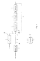
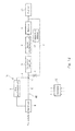
- Fig. 1 is a block diagram showing an exemplary configuration of a hydrogen generation device according to Embodiment 1.
- the hydrogen generation device according to Embodiment 1 includes a reformer 1, a first desulfurization unit 2, a second desulfurization unit 3, a branch passage 4, a raw material passage 5, a switch unit 6, a recycle passage 7, a flow control unit 8, a raw material supply unit 9 and a controller 12.
- the reformer 1 generates a hydrogen-containing gas using the raw material.
- the reformer 1 includes a reforming catalyst (not shown).
- the reformer 1 generates a hydrogen-containing gas by proceeding a steam reforming reaction using the raw material and steam by an action of the reforming catalyst.
- the reforming catalyst for example, a Ru catalyst, a Ni catalyst, etc., is used.
- the generated hydrogen-containing gas is sent out through an exit of the reformer 1.
- the raw material is supplied to the reformer 1 through a raw material supply path as will be described later.
- the steam is supplied to the reformer 1 through a water supply path (not shown).
- the reformer 1 is heated up to a predetermined temperature (e.g., 650 degrees C) by a heater (not shown), and thus is supplied with heat required for the steam reforming reaction.
- a predetermined temperature e.g., 650 degrees C
- a shift converter for reducing carbon monoxide in the hydrogen-containing gas generated in the reformer 1 by a shift reaction
- a CO reducing unit for reducing carbon monoxide in the hydrogen-containing gas by at least either an oxidation reaction or a methanation reaction.
- the reforming reaction proceeding in the reformer 1 is not limited to the above stated steam reforming reaction, but may be any reforming reaction so long as the hydrogen-containing gas is generated through the reaction using the raw material.
- the reforming reaction may be a partial oxidation reaction or an autothermal reaction.
- a downstream end of the raw material supply path is connected to an entrance of the reformer 1.
- An upstream end of the raw material supply path is connected to a raw material supply source (not shown).
- the raw material is a gas containing an organic compound including at least hydrogen and carbon as elements.
- hydrocarbon gases such as a city gas including methane as a major component, a natural gas and LPG
- the raw material contains a sulfur compound which is an odorous component or originates from the raw material.
- the raw material source there are an infrastructure of the raw material, a tank for storing the raw material, etc..
- the raw material supply path is configured to include the branch passage 4, the raw material passage 5, and the switch unit 6. The raw material from the raw material source is supplied to the switch unit 6.
- the switch unit 6 performs switching of a supply destination of the supplied raw material between the branch passage 4 and the raw material passage 5.
- the switch unit 6 is constituted by, for example, a three-way valve, on-off valves provided in the branch passage 4 and the raw material passage 5, respectively, etc..
- the branch passage 4 and the raw material passage 5 are joined together at a joint 11.
- the branch passage 4 is provided with a first desulfurization unit 2.
- the first desulfurization unit 2 removes the sulfur compound from the raw material at a room temperature by physical adsorption/desulfurization.
- the "room temperature” means a temperature that is relatively closer to a room temperature range than a use temperature (typically, about 300 degrees C) of a hydrodesulfurization catalyst, and falls in a range from the room temperature range to a temperature at which a desulfurization agent used in the first desulfurization unit 2 works effectively.
- the desulfurization agent for example, there are a zeolite-based adsorbing agent in which Ag removing the odorous component is ion-exchanged, active carbon, etc..
- the raw material passage 5 is a passage used to flow the raw material supplied to the reformer 1 through only the second desulfurization unit 3 of the first desulfurization unit 2 and the second desulfurization unit 3.
- the raw material passage 5 bypasses the first desulfurization unit 2, passes through only the second desulfurization unit 3 and is connected to the reformer 1.
- the raw material supply unit 9 adjusts a flow (flow rate) of the raw material supplied to the reformer 1.
- the raw material supply unit 9 includes, for example, a booster such as a booster pump and a flow control valve.
- the raw material supply unit 9 is not limited to this and may be either one of the booster and the flow control valve.
- the second desulfurization unit 3 hydrodesulfurizes the sulfur compound from the raw material.
- hydrodesulfurization catalyst for example, there are first to third hydrodesulfurization catalysts.
- the first hydrodesulfurization catalyst is configured such that the CoMo-based catalyst and the ZnO catalyst are placed in this order in the flow of the raw material.
- the second hydrodesulfurization catalyst is configured such that the CoMo-based catalyst and the CuZnO catalyst are placed in this order in the flow of the raw material.
- the third hydrodesulfurization catalyst is configured to include the CuZn-based catalyst.
- the CoMo-based catalyst converts the sulfur compound in the raw material into hydrogen sulfide. Hydrogen sulfide produced by the conversion is chemically adsorbed onto the ZnO catalyst.
- the CoMo-based catalyst converts the sulfur compound in the raw material into hydrogen sulfide. Hydrogen sulfide produced by the conversion is chemically adsorbed onto the CuZnO catalyst.
- the second hydrodesulfurization catalyst may include both of the ZnO-based catalyst and the CuZn-based catalyst as the chemical adsorbing agents of hydrogen sulfide. Which of the ZnO-based catalyst and the CuZn-based catalyst is placed at an upstream side does not matter.
- the CuZn-based catalyst converts the sulfur compound in the raw material into hydrogen sulfide. Hydrogen sulfide produced by the conversion is adsorbed onto the CuZn-based catalyst.
- the CuZn-based catalyst is able to also adsorb the sulfur compound in the raw material which is not converted into hydrogen sulfide.
- the second desulfurization unit 3 carries out hydrodesulfurization at a specified temperature (e.g., 300 to 400 degrees C) higher than a room temperature.
- the specified temperature is set to include at least a portion of the use temperature of the hydrodesulfurization catalyst.
- the use temperature refers to a temperature suitable for use of the hydrodesulfurization catalyst, at which a desulfurization capability is exercised properly.
- the second desulfurization unit 3 is placed in the vicinity of the reformer 1, and is configured to be heated by heat transmitted from the reformer 1.
- the second desulfurization unit 3 may be heated by a heat source independent of the reformer 1, such as an electric heater, or heated by heat transmitted from at least one of the shift converter (not shown) and the CO removing unit (not shown).
- the hydrogen generation device of Embodiment 1 includes a first path 31 used to supply the raw material to the reformer 1 through at least the first desulfurization unit 2, and a second path 32 used to supply the raw material to the reformer through only the second desulfurization unit, of the first desulfurization unit and the second desulfurization unit.
- the second path 32 is constituted by the raw material passage 5.
- the first path 31 is constituted by the branch passage 4 and a portion of the raw material passage 5 which is located downstream of the joint 11.
- the first path 31 is configured such that the raw material is supplied to the reformer 1 through the first desulfurization unit 2 and the second desulfurization unit 3.
- the first path 31 is not limited to the present example, so long as the first path 31 is configured such that the raw material passes through at least the first desulfurization unit 2.
- Another configuration of the first path 31 will be described in detail later in modified example 1 of Embodiment 1.
- the switch unit 6 serves to switch the supply path through which the raw material is supplied to the reformer 1, between the first path 31 and the second path 32.
- the hydrogen generation device of Embodiment 1 includes a third path used to supply the hydrogen-containing gas generated in the reformer 1 to the second desulfurization unit 3.
- the third path is constituted by a recycle passage 7.
- the recycle passage 7 is provided with an on-off valve 8 as an example of a flow control unit.
- the flow control unit is not limited to the present example so long as it is able to selectively enable or inhibit the flow of the hydrogen-containing gas from an upstream end of the recycle passage 7 toward a downstream end of the recycle passage 7. Another example of the flow control unit will be described in Embodiment 3 to 6.
- downstream end of the recycle passage 7 is joined to a portion of the raw material passage 5 which is located between the raw material supply unit 9 and the joint 11.
- the upstream end of the recycle passage 7 is connected to a gas passage which is provided downstream of the reformer 1.
- the upstream end of the recycle passage 7 may be connected to any location so long as it is connected to the gas passage which is provided downstream of the reformer 1.
- the upstream end of the recycle passage 7 may be connected to, for example, a gas passage which is provided between the reformer 1 and a reactor located downstream of the reformer 1, a gas passage provided downstream of the shift converter, or a gas passage provided downstream of the CO reducing unit.
- the recycle passage 7 may be provided with a condenser (not shown) for lowering a dew point of the recycled gas.
- the downstream end of the recycle passage 7 is not limited to the above example, and may be connected to any location so long as it is a path provided upstream of the second desulfurization unit 3.
- the path provided upstream of the second desulfurization unit 3 is either the first path 31 or the second path 32.
- the recycle passage 7 may be provided with a suitable booster.
- the controller 12 controls the switch unit 6 and the flow control unit. Specifically, the controller 12 is configured to execute processing in such a manner that in at least either a time point before generation of the hydrogen-containing gas is stopped, or start-up, while the reformer 1 is generating the hydrogen-containing gas, the switch unit 6 performs switching to select the first path 31, and the flow control unit enables the flow of the hydrogen-containing gas. It is sufficient that the controller 12 has a control function.
- the controller 12 includes a processor section (not shown) and a storage section (not shown) for storing control programs. As examples of the processor section, there are MPU and CPU. As an example of the storage section, there is a memory.
- the controller 12 may be a single controller or a controller group in which a plurality of controllers cooperate with each other to execute control.
- the processor section of the controller 12 reads the control program stored in the storage section and executes it, thereby executing control as will be described later.
- Fig. 2 is a flowchart showing an exemplary operation of the hydrogen generation device of Fig. 1 .
- the controller 12 executes processing in such a manner that in at least either the time point before generation of the hydrogen-containing gas is stopped, or start-up, while the reformer 1 is generating the hydrogen-containing gas (step S1), the switch unit 6 performs switching to select the first path 31, and the flow control unit enables the hydrogen-containing gas to flow from the upstream end of the recycle passage 7 toward the downstream end of the recycle passage 7 (step S2, step S3).
- the on-off valve 8 which is the flow control unit is opened to enable the flow of the hydrogen-containing gas.
- the phrase "generation of the hydrogen-containing gas is stopped” means that supplying of the raw material to the reformer 1 is stopped in the middle of the generation of the hydrogen-containing gas.
- the controller 12 causes the raw material supply unit 9 to stop supplying of the raw material to the reformer 1.
- step S1 to step S3 may be initiated in a desired order. That is, the three steps may be all initiated at the same time, or otherwise, one, two or all of these steps may be initiated at different timings. In the latter case, step S 1 to step S3 may be initiated in any order.
- the witch unit 6 performs switching to select the second path 32, and the on-off valve 8 which is the flow control unit is opened to enable the flow of the hydrogen-containing gas. That is, the raw material supplied to the reformer 1 bypasses the first desulfurization unit 2, and is added with a part of the hydrogen-containing gas generated in the reformer 1 via the recycle passage 7. Then, the raw material added with the hydrogen-containing gas is supplied to the second desulfurization unit 3, which hydrodesulfurizes the raw material, and supplies the hydrodesulfurized raw material to the reformer 1.
- the controller 12 causes the raw material supply unit 9 to continue supplying of the raw material to the reformer 1, the reformer 1 to generate the hydrogen-containing gas, and the on-off valve 8 to be opened to enable the flow of the hydrogen-containing gas.
- the controller 18 causes the switch unit 6 to perform switching to select the first path 31 in place of the second path 32.
- the phrase "when the hydrogen generation device is stopped” means that the reformer 1 is going to stop generation of the hydrogen-containing gas soon. Specifically, as examples of "when the hydrogen generation device is stopped”, there are a time which is when planned stop time of the hydrogen generation device is approaching, when an operator inputs a stop command of the hydrogen generation device via a manipulation device (e.g., remote controller), etc..
- a manipulation device e.g., remote controller
- the controller 12 causes the raw material supply unit 9 to stop supplying of the raw material to the reformer 1, and the on-off valve 8 which is the flow control unit to be closed to inhibit the flow of the hydrogen-containing gas, thereby stopping the hydrogen generation device. That is, before the generation of the hydrogen-containing gas in the reformer 1 is stopped, i.e., prior to stop of the generation of the hydrogen-containing gas in the reformer 1, the above processing is executed.
- the switch unit 6 maintains the state in which the second path 32 is selected. Therefore, the hydrogen-containing gas supplied to the second desulfurization unit 3 is consumed in a hydrogenation reaction of the sulfur compound contained in the raw material gas which is newly supplied to the second desulfurization unit 3 and from which the sulfur compound is not removed yet. Therefore, the hydrogen generation device is stopped in a state in which the unhydrogenated sulfur compound is left on the hydrodesulfurization catalyst of the second desulfurization unit 3. Then, at next start-up of the hydrogen generation device, when the raw material is supplied to the second desulfurization unit 3, a problem may arise in some cases.
- Adsorbing and removing of the unhydrogenated sulfur compound which is physical adsorption, requires a greater adsorbing capacity than adsorbing and removing of hydrogen sulfide, which is chemical adsorption. If an attempt is made to ensure an adsorbing capacity of the CuZn-based catalyst for the unhydrogenated sulfur compound, which is desorbed from the CoMo-based catalyst, a size and cost of the second desulfurization unit increase. Also, in a case where the hydrodesulfurization catalyst is the third hydrodesulfurization catalyst, the amount of the unhydrogenated sulfur compound which is adsorbed onto the surface of CuZnO increases, causing its desulfurization capability to degrade. As a result, sulfur poisoning of the reforming catalyst will progress.
- the raw material which has been desulfurized by the first desulfurization unit 2 is supplied to the second desulfurization unit 3, and the hydrogen-containing gas is generated in the reformer 1 and supplied to the second desulfurization unit 3.
- the unhydrogenated sulfur compound adhering onto the hydrodesulfurization catalyst is hydrogenated and hydrogen sulfide generated by the hydrogenation is adsorbed and removed.
- the hydrogen generation device of the present embodiment is able to reduce a possibility of a problem caused by the fact that, at start-up, the unhydrogenated sulfur compound left on the hydrodesulfurization catalyst of the second desulfurization unit 3, is supplied to the reformer along with the raw material, as compared to the conventional hydrogen generation device.
- the hydrogen generation device executes the following processing. Specifically, at-start up, the controller 12 raises the temperature of the reformer 1 and the temperature of the second desulfurization unit 3. When the temperature of the reformer 1 reaches a temperature at which the hydrogen-containing gas can be generated, the controller 12 supplies the steam to the reformer 1 and causes the raw material supply unit 9 to supply the raw material to the reformer 1, thus initiating generation of the hydrogen-containing gas in the reformer 1.
- the controller 12 causes the on-off valve 8 which is the flow control unit to be opened to enable the flow of the hydrogen-containing gas and the switch unit 6 to perform switching to select the first path 31.
- the hydrogen-containing gas generated in the reformer 1 is supplied to the second desulfurization unit 3. Therefore, as described above, the unhydrogenated sulfur compound adhering onto the hydrodesulfurization catalyst is hydrogenated and hydrogen sulfide generated by the hydrogenation is adsorbed and removed.
- the controller 12 causes the switch unit 6 to perform switching to select the second path 32.
- the controller 12 causes the hydrogen generation device to operate as in the operation example 2, while during a hydrogen generation operation of the hydrogen generation device and at stop of the hydrogen generation device, the controller 12 causes the hydrogen generation device to operate as in the operation example 1. This makes it possible to reduce a possibility of a problem caused by the unhydrogenated sulfur compound left on the hydrodesulfurization catalyst of the second desulfurization unit 3, as compared to the conventional hydrogen generation device.
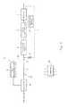
- Fig. 3 is a block diagram showing an exemplary configuration of the hydrogen generation device according to modified example 1 of Embodiment 1.
- the first path 31 is configured such that the raw material is supplied to the reformer 1 only through the first desulfurization unit 2. Except for this, the configuration of modified example 1 is identical to that of Embodiment 1 (configuration of Fig. 1 ).
- the downstream end of the branch passage 4 is joined at the joint 11 to a portion of the raw material passage 5 which is located downstream of the second desulfurization unit 3.
- the other components which are designated by the same reference symbols as those in Fig. 1 are identical to those of Embodiment 1, and will not be described in detail.
- the controller 12 executes processing in such a manner that while the reformer 1 is generating the hydrogen-containing gas, the switch unit 6 performs switching to select the first path 31, and the on-off valve 8 which is the flow control unit is opened to enable the flow of the hydrogen-containing gas, the raw material supply unit 9 supplies the raw material having been desulfurized by the first desulfurization unit 2, to the reformer 1, and the hydrogen-containing gas generated in the reformer 1 is supplied to the second desulfurization unit 3 via the recycle passage 7.
- the unhydrogenated sulfur compound adhering onto the hydrodesulfurization catalyst of the second desulfurization unit 3 is hydrogenated, and as a result, it becomes possible to reduce a possibility of a problem caused by the unhydrogenated sulfur compound left on the hydrodesulfurization catalyst of the second desulfurization unit 3, as compared to the conventional hydrogen generation device.
- the controller 12 causes the switch unit 6 to perform switching to select the second path 32, the raw material which has passed through only the second desulfurization unit 3 is supplied to the reformer 1, as in the configuration of Fig. 1 .
- the controller is configured to execute processing in such a manner that when an operation (running) time passes a first time threshold, during the operation of the hydrogen generation device, the switch unit performs switching to select the first path, and the flow control unit enables flow of the hydrogen-containing gas, while the reformer is generating the hydrogen-containing gas, in the hydrogen generation device of Embodiment 1 or modified example 1.
- a timing when the measurement of the operation time starts is set as desired.
- the timing when the measurement of the operation time starts may be time when supplying of the raw material to the second desulfurization unit 3 starts, time when generation of the hydrogen-containing gas in the reformer 1 starts, etc..
- the first time threshold is time by which it is determined that the above processing should be executed and is set as desired.
- the first time threshold is 24h from start of power generation (start-up of hydrogen generation device). It should be noted that the first time threshold may be changed based on a power generation history of each customer who utilizes the fuel cell system.
- the first time threshold is set according to an accumulated supply amount of the raw material supplied to the second desulfurization unit, in the hydrogen generation device of modified example 2.
- the controller is configured to execute processing in such a manner that the switch unit performs switching to select the first path, and the flow control unit enables flow of the hydrogen-containing gas, while the reformer is generating the hydrogen-containing gas, for a predetermined time or longer, in the hydrogen generation device of any one of Embodiment 1 and modified examples 1 to 3.
- the predetermined time is set to a time required to supply the hydrogen-containing gas generated in the reformer to the second desulfurization unit and to hydrogenate the unhydrogenated sulfur compound adhering onto the hydrodesulfurization catalyst of the second desulfurization unit. This time is decided through an experiment, etc..
- the "predetermined time” may be set according to the accumulated supply amount of the raw material supplied to the second desulfurization unit.
- the controller is configured to cause the switch unit to perform switching to select the second path when the temperature of the hydrodesulfurization catalyst provided in the second desulfurization unit is its use temperature, in the hydrogen generation device of any one of Embodiment 1 and modified examples 1 to 4.
- the undesulfurized raw material is supplied to the second desulfurization unit, but the temperature of the hydrodesulfurization catalyst provided in the second desulfurization unit has reached its use temperature, and therefore its desulfurization capability is exercised properly.
- the hydrogen generation device of the present modified example is configured like the hydrogen generation device of Embodiment 1 shown in Fig. 1 , and will not be described in detail.
- the controller 12 is configured to cause the switch unit 6 to perform switching to select the second path 32 when the temperature of the hydrodesulfurization catalyst provided in the second desulfurization unit 3 is its use temperature. At this time, the on-off valve 8 is opened to enable the hydrogen-containing gas to flow from the upstream end of the recycle passage 7 to the downstream end of the recycle passage 7.
- Step S3 of Fig. 2 is executed.
- the switch unit 6 selects the first path 31, and the on-off valve 8 is kept to be opened. Thereafter, the switch unit 6 performs switching to select the second path 32. Its timing is set as desired.
- the switch unit 6 may perform switching to select the second path 32, when the temperature of the hydrodesulfurization catalyst provided in the second desulfurization unit 3 is its use temperature, or when the temperature of the hydrodesulfurization catalyst provided in the second desulfurization unit 3 is lower than its use temperature.
- the controller is configured to, in the above stated processing at start-up, cause the flow control unit to initiate flowing of the hydrogen-containing gas, when the temperature of the hydrodesulfurization catalyst provided in the second desulfurization unit is lower than its use temperature, in the hydrogen generation device of any one of Embodiment 1 and modified examples 1 to 5.
- the hydrogen generation device of the present embodiment may be configured like the hydrogen generation device of any one of Embodiment 1, and modified examples 1 to 5, except for the above features.
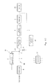
- Fig. 4 is a block diagram showing an exemplary configuration of the hydrogen generation device according to Embodiment 2.
- the controller 12 is configured to execute the above processing in such a manner that when the temperature of the hydrodesulfurization catalyst provided in the second desulfurization unit 3 is lower than its use temperature, at start-up, the switch unit 6 performs switching to select the first path 31, and in this state, the on-off valve 8 which is an example of the flow control unit is opened to enable the flow of the hydrogen-containing gas, while the reformer 1 is generating the hydrogen-containing gas.
- the above stated temperature which is lower than the use temperature of the hydrodesulfurization catalyst provided in the second desulfurization unit 3, is set as desired.
- the use temperature of the hydrodesulfurization catalyst is a temperature suitable for use of the hydrodesulfurization catalyst.
- the hydrodesulfurization reaction proceeds. Therefore, even when the hydrogen-containing gas is supplied to the second desulfurization unit, under a state of a temperature which is lower than the use temperature of the hydrodesulfurization catalyst but allows the hydrodesulfurization reaction to proceed, the unhydrogenated sulfur compound on the hydrodesulfurization catalyst is hydrogenated into hydrogen sulfide, which is adsorbed and removed.
- the controller 12 causes the switch unit 6 to perform switching to select the second path 32, and raises the temperature of the second desulfurization unit 3.
- the other configuration is identical to that of the operation example 2 of the hydrogen generation device of Embodiment 1.
- the hydrogen generation device of the present embodiment includes a detector for detecting the temperature of the hydrodesulfurization catalyst provided in the second desulfurization unit 3.
- This detector may directly or indirectly detect the temperature of the select desulfurization unit 3.
- the phrase "the detector directly detects” means that it detects the temperature of the hydrodesulfurization catalyst provided in the second desulfurization unit 3.
- the phrase "the detector indirectly detects” means that it detects a physical amount (parameter) having a correlation with the temperature of the hydrodesulfurization catalyst provided in the second desulfurization unit 3.
- the example of the hydrogen generation device of Fig. 4 includes a temperature detector 13 for detecting the temperature of the hydrodesulfurization catalyst provided in the second desulfurization unit 3, to directly detect the temperature of the hydrodesulfurization catalyst provided in the second desulfurization unit 3.
- the temperature detector 13 there is a temperature sensor such as a thermocouple or a thermistor.
- the detector for detecting the temperature of the hydrodesulfurization catalyst may be a temperature detector for detecting the temperature of the reformer 1. Based on the temperature of the reformer 1 detected by this temperature detector, the temperature of the second desulfurization unit 3 is indirectly detected.
- the detector for detecting the temperature of the second desulfurization unit 3 may be a timer for detecting time that passes after the start-up of the hydrogen generation device. Based on the time measured by the timer, the temperature of the second desulfurization unit 3 is indirectly detected.
- the flow control unit in the present example, on-off valve 8 is caused to initiate flowing of the hydrogen-containing gas under a temperature which is equal to or lower than an upper limit temperature at which the unhydrogenated sulfur compound adhering onto the hydrodesulfurization catalyst of the second desulfurization unit 3 is not desorbed therefrom.
- a temperature threshold of the second desulfurization unit at which the flow control unit is caused to initiate flowing of the hydrogen-containing gas may be any temperature so long as it is equal to or lower than the use temperature and allows the unhydrogenated sulfur compound adhering onto the hydrodesulfurization catalyst of the second desulfurization unit 3 to be hydrogenated.
- the temperature threshold may be found through an experiment or the like.
- the second desulfurization unit 3 may be configured such that its temperature is controllable independently of the reformer 1.
- the second desulfurization unit 3 may be heated by a heater such as an electric heater which is separate from the reformer 1.
- the second desulfurization unit 3 may be heated by the heat transmitted from the reformer 1 such that an amount of the heat is adjustable.
- the controller 12 controls the temperature of the second desulfurization unit 3 by controlling the amount of heat given to the second desulfurization unit 3.
- Fig. 5 is a flowchart showing an exemplary processing operation of the hydrogen generation device according to Embodiment 3.
- the controller 12 causes the switch unit 6 to perform switching to select the first path 31 and the reformer 1 to generate the hydrogen-containing gas, under a temperature which is equal to or lower than the use temperature of the hydrodesulfurization catalyst provided in the second desulfurization unit 3 (step S11). Specifically, at start-up, the controller 12 raises the temperature of the reformer 1 and the temperature of the second desulfurization unit 3.
- the switch unit 6 When the temperature of the reformer 1 has reached a temperature at which the reforming reaction can proceed, the switch unit 6 performs switching to select the first path 31, so that the raw material which has passed through the first desulfurization unit 2 is supplied to the reformer 1, which generates the hydrogen-containing gas.
- the controller 12 determines whether or not the temperature detected by the temperature detector 13 is equal to or higher than a temperature threshold T1 (step S12). When the controller 12 determines that the temperature is equal to or higher than the temperature threshold T1 (Yes in step S12), it controls the flow control unit (on-off valve 8) to enable the flow of the hydrogen-containing gas (step S13). As a result, the hydrogen-containing gas is supplied to the second desulfurization unit 3 via the recycle passage 7.
- the temperature threshold T1 is defined as a temperature which is lower than the use temperature and allows the hydrodesulfurization reaction to proceed.
- the second desulfurization unit may include a hydrodesulfurization catalyst which desorbs the unhydrogenated sulfur compound when the raw material is supplied to the second desulfurization unit under a temperature which is lower than the use temperature of the hydrodesulfurization catalyst, and the controller may control the flow control unit to enable the flow of the hydrogen-containing gas, under a temperature which is equal to or lower than the upper limit temperature at which the unhydrogenated sulfur compound is not desorbed from the hydrodesulfurization catalyst, in the hydrogen generation device of any one of Embodiment 1, modified examples 1 to 5, and Embodiment 2.
- this upper limit temperature is desirably 150 degrees C.
- the hydrogen generation device of the present embodiment may be configured like the hydrogen generation device of any one of Embodiment 1, modified examples 1 to 5, and Embodiment 2, except for the above features.
- a specific configuration of the hydrogen generation device according to embodiment 3 is identical to that of Embodiment 2 of Fig. 4 , and will not be described in detail.
- the second desulfurization unit 3 includes the hydrodesulfurization catalyst which desorbs the unhydrogenated suflur compound if the raw material is supplied to the second desulfurization unit 3 under a temperature which is lower than the use temperature.
- the controller 12 executes the above processing in such a manner that at start-up, when the temperature of the hydrodesulfurization catalyst provided in the second desulfurization unit 3 is equal to or lower than the upper limit temperature at which the unhydrogenated sulfur compound is not desorbed from the hydrodesulfurization catalyst, the switch unit 6 performs switching to select the first path 31, and in this state, the on-off valve 8 which is an example of the flow control unit is opened to enable the flow of the hydrogen-containing gas, while the reformer 1 is generating the hydrogen-containing gas.
- the upper limit temperature is 150 degrees C. However, the upper limit temperature is different depending on the kind of hydrodesulfurization catalyst.
- a temperature threshold which is equal to or lower than the upper limit temperature, at which the flow control unit is caused to initiate flowing of the hydrogen-containing gas may be any temperature so long as the temperature is equal to or lower than the above stated use temperature and allows the unhydrogenated sulfur compound adhering onto the hydrodesulfurization catalyst to be hydrogenated. This temperature threshold can be found through an experiment, etc.. After that, the controller 12 causes the switch unit 6 to perform switching to select the second path 32, and raises the temperature of the second desulfurization unit 3.
- the other configuration is identical to that of the operation example 2 of the hydrogen generation device of Embodiment 1.
- the specific processing operation of the hydrogen generation device according to Embodiment 3 is identical to that of Embodiment 2 except that the temperature threshold T1 is set to the temperature lower than the temperature which is equal to or lower than the upper limit temperature in place of the temperature lower than the use temperature, in the processing operation of Embodiment 2. It should be noted that the temperature threshold T1 is desirably a temperature which allows the hydrodesulfurization reaction to proceed.
- Embodiment 1 Embodiment 1, Embodiment 2, and Embodiment 3 will be described.
- the CoMo-based catalyst of 10cc and the ZnO-based catalyst of 5cc as the hydrodesulfurization catalysts were provided in a fixed bed flow reactor including an electric furnace, and experiments which simulated behaviors at stop and re-start-up of the hydrogen generation device were conducted. That is, the case where the hydrodesulfurization catalyst was the first hydrodesulfurization catalyst was simulated.
- 13A As the raw material, 13A (hereinafter will be referred to as desulfurized 13A) from which a sulfur component was removed by adsorption using a zeolite-based adsorbing/desulfurization agent was supplied to the fixed bed flow reactor with 50cc/min. This raw material was added with tert-butyl mercaptan (TBM) of 10ppm as a sulfur component and hydrogen of 5vol. %
- TBM tert-butyl mercaptan
- desorption of the sulfur component (TBM) was not observed when the temperature of the hydrodesulfurization catalyst was equal to or higher than 150 degrees C. It was estimated that this was due to the fact that when the gas with hydrogen added to the desulfurized 13A was supplied to the hydrodesulfurization catalyst, while addition of TBM was stopped, the unhydrogenated sulfur compound adhering onto the CoMo-based catalyst was hydrogenated into hydrogen sulfide, which was adsorbed onto the ZnO-based catalyst to be removed.
- the sulfur component (TBM) of the gas which passed through the hydrodesulfurization catalyst was equal to or less than the detection limit (5ppb). In other words, desorption of the sulfur component from the hydrodesulfurization catalyst was not observed when the temperature of the hydrodesulfurization catalyst was equal to or higher than 150 degrees C. It was estimated that if only hydrogen was supplied, without supplying the desulfurized 13A, in at least a time which was either when supplying of TMB was stopped or when temperature of the fixed bed flow reactor was re-raised, the unhydrogenated sulfur compound was hydrodesulfurized and the sulfur component (TBM) became the detection limit or less when temperature of the fixed bed flow reactor was re-raised, in the same manner.
- This experiment simulated the operation example 3 of Embodiment 1 as a whole.
- the present example supported that a problem caused by the unhydrogenated sulfur compound adhering onto the hydrodesulfurization catalyst was mitigated more effectively, in the embodiments and modified examples than in the conventional example.
- the hydrodesulfurization catalyst was a catalyst which desorbed the unhydrogenated sulfur compound when the gas was supplied to the hydrodesulfurization catalyst under a temperature lower than its use temperature
- desorption of the unhydrogenated sulfur compound from the catalyst did not occur if the hydrogen-containing gas was supplied to the second desulfurization unit 3 under a temperature which was equal to or lower than the upper limit temperature (150 degrees C).
- the switch unit 6 performs switching to select the first path 31 and in this state, the flow of the hydrogen-containing gas in the recycle passage 7 is enabled, under a temperature higher than the upper limit temperature (150 degrees C), the unhydrogenated sulfur compound is thereafter hydrogenated into hydrogen sulfide, which is adsorbed onto the catalyst. Therefore, even in such a case, it is obvious that the problem caused by the unhydrogenated sulfur compound can be mitigated more effectively, than in the conventional hydrogen generation device.
- the CuZnO-based catalyst of 500cc as the hydrodesulfurization catalyst was provided in the fixed bed flow reactor including the electric furnace, and experiments which simulated behaviors at stop and re-start-up of the hydrogen generation device were conducted. That is, the case where the hydrodesulfurization catalyst was the third hydrodesulfurization catalyst was simulated.
- 13A As the raw material, 13A (hereinafter will be referred to as desulfurized 13A) from which the sulfur component was removed by adsorption using the zeolite-based adsorbing/desulfurization agent was supplied to the fixed bed flow reactor with 3L/min. This raw material was added with tertiary butyl mercaptan (DMS) of 500ppm as the sulfur component and hydrogen of 5vol. %
- DMS tertiary butyl mercaptan
- hydrodesulfurization was conducted at 300 to 400 degrees C. After continuing to supply the raw material having been added with the sulfur component and hydrogen to the fixed bed flow reactor, for 81h, supplying of DMS and supplying of hydrogen were stopped at the same time.
- the sulfur component (DMS) in the gas which passed through the hydrodesulfurization catalyst was equal to or less than the detection limit (5ppb).
- the sulfur component (DMS) of 300ppb was detected.
- the sulfur component (DMS) in the gas which passed through the hydrodesulfurization catalyst under the use temperature (in the present example, 250 degrees C) of the hydrodesulfurization catalyst was equal to or less than the detection limit (5ppb). It was estimated that this was due to the fact when the gas with hydrogen added to the desulfurized 13A was supplied to the hydrodesulfurization catalyst in a state in which addition of DMS was stopped, the unhydrogenated sulfur compound adhering onto the CuZnO-based catalyst was hydrodesulfurized, and thus a desulfurization capability of the CuZnO-based catalyst was restored.
- the sulfur component (DMS) in the gas was equal to or less than the detection limit (5ppb). It was estimated that this was due to the fact that when the desulfurized 13A added with hydrogen was supplied under the state in which the temperature of the fixed bed flow reactor was re-raised, the unhydrogenated sulfur compound adhering onto the CuZnO-based catalyst was hydrodesulfurized, and thus the desulfurization capability of the CuZnO-based catalyst was restored.
- the sulfur component (DMS) of the gas which passed through the hydrodesulfurization catalyst was equal to or less than the detection limit (5ppb). It was estimated that if only hydrogen was supplied, without supplying the desulfurized 13A, in at least a time which was either when supplying of DMS was stopped or when temperature of the fixed bed flow reactor was re-raised, the unhydrogenated sulfur compound was hydrodesulfurized and the sulfur component (DMS) became the detection limit or less when temperature of the fixed bed flow reactor was re-raised, in the same manner.
- This experiment simulated the operation example 3 of Embodiment 1 as a whole.
- Fig. 6 is a block diagram showing a configuration in which the on-off valve 8 is replaced by another example of the flow control unit in the hydrogen generation device according to Embodiment 1, as a hydrogen generation device according to Embodiment 4.
- Fig. 7 is a block diagram showing a configuration in which the on-off valve 8 is replaced by another example of the flow control unit in the hydrogen generation device according to modified example 1 of Embodiment 1, as the hydrogen generation device according to Embodiment 4.
- the recycle passage 7 is provided with a specified pressure loss mechanism (passage resistance) 42.
- This pressure loss mechanism 42 is formed, for example, by providing an orifice having a specified pressure loss (flow rate), or designing a pipe diameter of the recycle passage 7 so that it has a specified diameter.
- a hydrogen-containing gas supply passage 40 is provided at an exit of the reformer 1.
- a pressure loss adjusting unit 41 is provided in a portion of the hydrogen-containing gas supply passage 40, which is located downstream of a branch point 40a of the recycle passage 7.
- the pressure loss adjusting unit 41 is constituted by, for example, a variable orifice which is able to adjust the pressure loss (flow rate).
- the pressure loss in the pressure loss adjusting unit 41 is adjusted by the controller 12.
- the recycle passage 7 is provided with a check valve 43. This check valve may be omitted.
- the controller 12 makes the pressure loss in the pressure loss adjusting unit 41 greater than the pressure loss mechanism 42 of the recycle passage 7. This enables the hydrogen-containing gas to flow from the upstream end of the recycle passage 7 toward the downstream end of the recycle passage 7.
- the controller 12 sets the pressure loss in the pressure loss adjusting unit 41 to substantially zero. This substantially inhibits the hydrogen-containing gas from flowing from the downstream end of the recycle passage 7 toward the upstream end of the recycle passage 7.
- the chick valve 43 prevents the raw material gas from flowing back into the hydrogen-containing gas supply passage 40 through the recycle passage 7 in a state in which the raw material supply unit 9 is deactivated.
- Embodiment 4 may be applied to any one of modified examples 2 to 5, Embodiment 2 and Embodiment 3.
- Fig. 8 is a block diagram showing a configuration in which the on-off valve 8 is replaced by another example of the flow control unit in the hydrogen generation device according to Embodiment 1, as a hydrogen generation device according to Embodiment 5.
- Fig. 9 is a block diagram showing a configuration in which the on-off valve 8 is replaced by another example of the flow control unit in the hydrogen generation device according to modified example 1 of Embodiment 1, as the hydrogen generation device according to Embodiment 4.
- the same configuration as that of Embodiment 3 will not be described, but differences from Embodiment 3 will be described.
- the recycle passage 7 is provided with a specified pressure loss mechanism (passage resistance) 42.
- a switch unit 44 is provided in a portion of the hydrogen-containing gas supply passage 40, which is located downstream of the branch point 40a of the recycle passage 7.
- the switch unit 44 performs switching to connect an upstream portion of the hydrogen-containing gas supply passage 40 which is located upstream of the switch unit 44, to a shortcut passage 40b or a bypass passage 40c.
- the shortcut passage 40b and the bypass passage 40c are joined together in a downstream portion of the hydrogen-containing gas supply passage 40 which is located downstream of the switch unit 44.
- the bypass passage 40b is provided with the pressure loss mechanism 45 greater than the pressure loss mechanism 42 in the recycle passage 7.
- This pressure loss mechanism 45 is formed, for example, by providing an orifice having a specified pressure loss (flow rate), or designing a pipe diameter of the bypass passage 40b so that it has a specified diameter.
- the switch unit 44 is constituted by, for example, a three-way valve or on-off valves provided in the shortcut passage 40b and the bypass passage 40c, respectively, etc.. The switching operation of the switch unit 44 is controlled by the controller 12.
- the controller 12 causes the switch unit 44 to perform switching to select the bypass passage 40c. This enables the hydrogen-containing gas to flow from the upstream end of the recycle passage 7 toward the downstream end of the recycle passage 7.
- the controller 12 causes the switch unit 44 to perform switching to select the shortcut passage 40b. This substantially inhibits the hydrogen-containing gas from flowing from the upstream end of the recycle passage 7 toward the downstream end of the recycle passage 7.
- Embodiment 5 may be applied to any one of modified examples 2 to 5, Embodiment 2 and Embodiment 3.
- the controller 12 executes the above processing in such a manner that the flow control unit enables the flow of the hydrogen-containing gas, when a temperature of the third path reaches a temperature at which water condensation in the third path does not occur, in the hydrogen generation device of any one of Embodiment 1, modified examples 1 to 5, Embodiment 2 and Embodiment 3.
- the hydrogen generation device of the present embodiment may be configured like the hydrogen generation device of any one of Embodiment 1, modified examples 1 to 5, Embodiment 2 and Embodiment 3, except for the above features.
- Fig. 10 is a block diagram showing an exemplary configuration of the hydrogen generation device according to Embodiment 6.
- the hydrogen generation device of the present embodiment includes a temperature detector 14 for detecting the temperature of the recycle passage 7.
- a temperature detector 14 for detecting the temperature of the recycle passage 7.
- the other components which are designated by the same reference symbols as those in Fig. 1 are identical to those of Embodiment 1, and will not be described in detail.
- the hydrogen generation device of the present embodiment includes the temperature detector for detecting the temperature of the recycle passage 7.
- This detector may directly or indirectly detect the temperature of the recycle passage 7.
- the phrase "the detector directly detects” means that it detects the temperature of the recycle passage 7.
- the phrase “the detector indirectly detects” means that it detects a physical amount (parameter) having a correlation with the temperature of the recycle passage 7.
- the example of the hydrogen generation device of Fig. 10 includes a temperature detector 14 for detecting the temperature of the recycle passage 7, to directly detect the temperature of the recycle passage 7.
- the temperature detector 14 there is a temperature sensor such as a thermocouple or a thermistor.
- the detector for detecting the temperature of the recycle passage 7 may be a temperature detector for detecting the temperature of the heat source. Based on the temperature of the heat source detected by this temperature detector, the temperature of the second desulfurization unit 3 is indirectly detected.
- the detector for detecting the temperature of the second desulfurization unit 3 may be a timer for detecting time that passes after the start-up of the hydrogen generation device. Based on the time measured by the timer, the temperature of the second desulfurization unit 3 is indirectly detected.
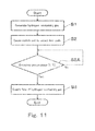
- Fig. 11 is a flowchart showing the exemplary operation of the hydrogen generation device of Embodiment 6.
- the controller 12 executes processing in such a manner that while the reformer 1 is generating the hydrogen-containing gas (step S1), the switch unit 6 performs switching to select the first path 31 (step S2). Then, the controller 12 determines whether or not the temperature detected by the temperature detector 14 is equal to or higher than a temperature threshold T2.
- the controller 12 determines that the detected temperature is equal to or higher than the temperature threshold T2 (step S2A)
- the on-off valve 8 which is the flow control unit is opened to enable the flow of the hydrogen-containing gas.
- step S 1 to step S3 may be initiated in a desired order. That is, the three steps may be all initiated at the same time, or otherwise, one, two or all of these steps may be initiated at different timings. In the latter case, step S 1 to step S3 may be initiated in any order.
- Embodiment 7 includes the hydrogen generation device of any one of Embodiment 1, modified examples 1 to 5, and Embodiments 2 to 6, and a fuel cell for generating electric power using the hydrogen-containing gas supplied from the hydrogen generation device.
- Fig. 12 is a block diagram showing an exemplary configuration of the hydrogen generation device according to Embodiment 7.
- the fuel cell system of Embodiment 7 includes the hydrogen generation device of Embodiment 1 and a fuel cell 21.
- the fuel cell 21 generates electric power using the hydrogen-containing gas supplied from the hydrogen generation device.
- the fuel cell 21 is not particularly limited.
- the fuel cell 21 there are a polymer electrolyte fuel cell, a solid oxide fuel cell, a phosphorous acid fuel cell, a molten carbonate fuel cell, etc..
- a hydrogen generation device, an operation method thereof, and a fuel cell system of the present invention are useful as a hydrogen generation device, an operation method thereof, a fuel cell system, etc., which can reduce a possibility that a problem occurs due to the fact that a sulfur compound which is not converted into hydrogen sulfide is adsorbed onto a hydrodesulfurization catalyst, as compared to a conventional example.
Landscapes
- Chemical & Material Sciences (AREA)
- Chemical Kinetics & Catalysis (AREA)
- Engineering & Computer Science (AREA)
- General Chemical & Material Sciences (AREA)
- Sustainable Energy (AREA)
- Life Sciences & Earth Sciences (AREA)
- Sustainable Development (AREA)
- Electrochemistry (AREA)
- Manufacturing & Machinery (AREA)
- Organic Chemistry (AREA)
- Combustion & Propulsion (AREA)
- General Health & Medical Sciences (AREA)
- Inorganic Chemistry (AREA)
- Health & Medical Sciences (AREA)
- Analytical Chemistry (AREA)
- Oil, Petroleum & Natural Gas (AREA)
- Hydrogen, Water And Hydrids (AREA)
- Fuel Cell (AREA)
Abstract
Description
- The present invention relates to a hydrogen generation device, an operation method thereof, and a fuel cell system. Particularly, the present invention relates to a hydrogen generation device, an operation method thereof, and a fuel cell system, which include a desulfurization unit for desulfurizing a raw material.
- A hydrogen generation device is used to supply, for example, a hydrogen-containing gas as a fuel gas to a fuel cell. The hydrogen generation device typically includes a reformer for generating the hydrogen-containing gas through a reforming reaction of a raw material and water. As the raw material, a city gas or the like is used. The city gas or the like contains a sulfur compound as an odorous component, etc.. Because the sulfur compound is a poisoning substance to a reforming catalyst used in the reforming reaction, it is necessary to remove the sulfur compound in some way or other.
- Under the circumstances, there has been proposed a hydrogen generation device which employs a method of removing the sulfur compound by normal-temperature adsorption (hereinafter will be referred to as normal-temperature adsorption/desulfurization, for example, see Patent Literature 1) or a method of removing the sulfur compound by hydrodesulfurization using hydrogen (e.g., see Patent Literature 2). The normal-temperature adsorption/desulfurization is easily handled because of no need for heating and hydrogen, but does not have a great adsorption capacity. On the other hand, the hydrodesulfurization is not easily handled because of a need for heating and hydrogen, but has a great adsorption capacity. Accordingly, there has been proposed a hydrogen generation device which employs the normal-temperature adsorption/desulfurization at start-up and then employs the hydrodesulfurization after generation of the hydrogen-containing gas is enabled (e.g., see Patent Literature 2).
-
- Patent Literature 1: Japanese Laid-Open Patent Application Publication No.
2004-228016 - Patent Literature 2: Japanese Laid-Open Patent Application Publication No.
Hei. 1-275697 - However, for the hydrogen generation device disclosed in
Patent Literature 2, a problem caused by the fact that the sulfur compound which is not converted into hydrogen sulfide is adsorbed onto a hydrodesulfurization catalyst was not specifically studied. - The present invention has been made to solve the above mentioned problem, and an object of the present invention is to provide a hydrogen generation device, an operation method thereof, and a fuel cell system, which can reduce a possibility that a problem occurs due to the fact that the sulfur compound which is not converted into hydrogen sulfide is adsorbed onto the hydrodesulfurization catalyst, as compared to a conventional example.
- According to an aspect of the present invention, a hydrogen generation device comprises a reformer for generating a hydrogen-containing gas using a raw material; a first desulfurization unit for adsorbing and desulfurizing a sulfur compound from the raw material supplied to the reformer; a second desulfurization unit for hydrodesulfurizing the sulfur compound from the raw material supplied to the reformer; a first path used to supply the raw material to the reformer through at least the first desulfurization unit; a second path used to supply the raw material to the reformer through only the second desulfurization unit of the first desulfurization unit and the second desulfurization unit; a switch unit for performing switching between the first path and the second path; a third path used to supply the hydrogen-containing gas generated in the reformer to the second desulfurization unit; a flow control unit which selectively enables or inhibits a flow of the hydrogen-containing gas from an upstream end of the third path toward a downstream end of the third path; and a controller configured to execute processing in such a manner that in at least either a time point before generation of the hydrogen-containing gas is stopped, or start-up, the switch unit performs switching to select the first path, and the flow control unit enables the flow of the hydrogen-containing gas, while the reformer is generating the hydrogen-containing gas.
- According to an aspect of the present invention, a fuel cell system comprises the above stated hydrogen generation device; and a fuel cell for generating electric power using the hydrogen-containing gas supplied from the hydrogen generation device.
- According to an aspect of the present invention, there is provided a method of operating a hydrogen generation device for generating a hydrogen-containing gas, comprising the steps of: supplying a raw material which has passed through a first desulfurization unit for removing a sulfur compound from the raw material, to the reformer; and supplying the hydrogen-containing gas generated in the reformer to a second desulfurization unit for hydrodesulfurizing the sulfur compound in the raw material, wherein both of the steps are executed in at least either a time point before generation of the hydrogen-containing gas is stopped, or start up.
- According to an aspect of the present invention, it becomes possible to provide a hydrogen generation device, an operation method thereof and a fuel cell system, which can reduce a possibility that a problem occurs due to the fact that a sulfur compound which is not converted into hydrogen sulfide is adsorbed onto a hydrodesulfurization catalyst, as compared to a conventional example.
-
- [
Fig. 1] Fig. 1 is a block diagram showing an exemplary configuration of a hydrogen generation device according toEmbodiment 1. - [
Fig. 2] Fig. 2 is a flowchart showing an exemplary processing operation of a hydrogenated sulfur compound in the hydrogen generation device ofFig. 1 . - [
Fig. 3] Fig. 3 is a block diagram showing an exemplary configuration of a hydrogen generation device according to modified example 1 ofEmbodiment 1. - [
Fig. 4] Fig. 4 is a block diagram showing an exemplary configuration of a hydrogen generation device according toEmbodiment 2. - [
Fig. 5] Fig. 5 is a flowchart showing an exemplary processing operation of a hydrogenated sulfur compound in the hydrogen generation device according toEmbodiment 2. - [
Fig. 6] Fig. 6 is a block diagram showing a configuration in which an on-offvalve 8 is replaced by another example of a flow control unit in the hydrogen generation device according toEmbodiment 1, as a hydrogen generation device according toEmbodiment 4. - [
Fig. 7] Fig. 7 is a block diagram showing a configuration in which the on-offvalve 8 is replaced by another example of the flow control unit in the hydrogen generation device according to modified example 1 ofEmbodiment 1, as the hydrogen generation device according toEmbodiment 4. - [
Fig. 8] Fig. 8 is a block diagram showing a configuration in which the on-offvalve 8 is replaced by another example of the flow control unit in the hydrogen generation device according toEmbodiment 1, as a hydrogen generation device according toEmbodiment 5. - [
Fig. 9] Fig. 9 is a block diagram showing a configuration in which the on-offvalve 8 is replaced by another example of the flow control unit in the hydrogen generation device according to modified example 1 ofEmbodiment 1, as the hydrogen generation device according toEmbodiment 5. - [
Fig. 10] Fig. 10 is a block diagram showing an exemplary configuration of a hydrogen generation device according toEmbodiment 6. - [
Fig. 11] Fig. 11 is a block diagram showing an exemplary operation of the hydrogen generation device according toEmbodiment 6. - [
Fig. 12] Fig. 12 is a block diagram showing an exemplary configuration of a fuel cell system according toEmbodiment 7. - In the course of study of the conventional hydrodesulfurization unit in the hydrogen generation device, the present inventors found out that a problem occurs due to the fact that the sulfur compound which is not converted into hydrogen sulfide is adsorbed onto a hydrodesulfurization catalyst as described below.
- In a case where the hydrodesulfurization catalyst is configured such that a CoMo-based catalyst and a ZnO catalyst are placed in this order in a flow of the raw material, an unhydrogenated sulfur compound, which is desorbed from the CoMo-based catalyst, is not adsorbed onto the ZnO catalyst and flows into a reforming catalyst. Because of this, the reforming catalyst degrades.
- In a case where the hydrodesulfurization catalyst is configured such that the CoMo-based catalyst and a CuZnO catalyst are placed in this order in a flow of the raw material, an unhydrogenated sulfur compound, which is desorbed from the CoMo-based catalyst, is adsorbed onto the CuZnO. However, due to this adsorption, it becomes necessary to increase the volume of the CuZnO catalyst. This results in an increase in a size and cost of the hydrodesulfurization unit.
- In a case where the hydrodesulfurization catalyst includes a CuZn-based catalyst, a desulfurization capability degrades if the amount of the unhydrogenated sulfur compound which is adsorbed onto a surface of CuZnO increases.
- The present invention has been made based on the above described findings.
- Hereinafter, embodiments of the present invention will be described with reference to the drawings. Throughout the drawings, the same or corresponding components are designated by the same reference symbols and will not be described in repetition.
- A hydrogen generation device according to
Embodiment 1 comprises a reformer for generating a hydrogen-containing gas using a raw material; a first desulfurization unit for adsorbing and desulfurizing a sulfur compound from the raw material supplied to the reformer; a second desulfurization unit for hydrodesulfurizing the sulfur compound from the raw material supplied to the reformer; a first path used to supply the raw material to the reformer through at least the first desulfurization unit; a second path used to supply the raw material to the reformer through only the second desulfurization unit of the first desulfurization unit and the second desulfurization unit; a switch unit for performing switching between the first path and the second path; a third path used to supply the hydrogen-containing gas generated in the reformer to the second desulfurization unit; a flow control unit which selectively enables or inhibits a flow of the hydrogen-containing gas from an upstream end of the third path toward a downstream end of the third path; and a controller configured to execute processing in such a manner that in at least either a time point before generation of the hydrogen-containing gas is stopped, or start-up, the switch unit performs switching to select the first path, and the flow control unit enables the flow of the hydrogen-containing gas, while the reformer is generating the hydrogen-containing gas. - In accordance with this configuration, it becomes possible to reduce a possibility that a problem occurs due to the fact that a sulfur compound which is not converted into hydrogen sulfide is adsorbed onto a hydrodesulfurization catalyst, as compared to a conventional example.
- In the hydrogen generation device according to
Embodiment 1, the second desulfurization unit may include a CoMo-based catalyst. - In the hydrogen generation device according to
Embodiment 1, the second desulfurization unit may include a CuZn-based catalyst. - According to
Embodiment 1, there is provided a method of operating a hydrogen generation device for generating a hydrogen-containing gas, comprising the steps of: supplying a raw material, which has passed a first desulfurization unit for removing a sulfur compound from the raw material, to the reformer; and supplying the hydrogen-containing gas generated in the reformer to a second desulfurization unit for hydrodesulfurizing the sulfur compound from the raw material, wherein both of the steps are executed in at least either a time point before generation of the hydrogen-containing gas is stopped or start up. - In accordance with this configuration, it becomes possible to reduce a possibility that a problem occurs due to the fact that the sulfur compound which is not converted into hydrogen sulfide is adsorbed onto the hydrodesulfurization catalyst, as compared to a conventional example.
- Hereinafter, an example of the hydrogen generation device according to
Embodiment 1 will be specifically described. -
Fig. 1 is a block diagram showing an exemplary configuration of a hydrogen generation device according toEmbodiment 1. As shown inFig. 1 , the hydrogen generation device according toEmbodiment 1 includes areformer 1, afirst desulfurization unit 2, asecond desulfurization unit 3, abranch passage 4, araw material passage 5, aswitch unit 6, arecycle passage 7, aflow control unit 8, a rawmaterial supply unit 9 and acontroller 12. - The
reformer 1 generates a hydrogen-containing gas using the raw material. For example, thereformer 1 includes a reforming catalyst (not shown). Thereformer 1 generates a hydrogen-containing gas by proceeding a steam reforming reaction using the raw material and steam by an action of the reforming catalyst. As the reforming catalyst, for example, a Ru catalyst, a Ni catalyst, etc., is used. The generated hydrogen-containing gas is sent out through an exit of thereformer 1. The raw material is supplied to thereformer 1 through a raw material supply path as will be described later. The steam is supplied to thereformer 1 through a water supply path (not shown). Thereformer 1 is heated up to a predetermined temperature (e.g., 650 degrees C) by a heater (not shown), and thus is supplied with heat required for the steam reforming reaction. At a downstream side of thereformer 1, there may be provided at least one of a shift converter (not shown) for reducing carbon monoxide in the hydrogen-containing gas generated in thereformer 1 by a shift reaction, and a CO reducing unit (not shown) for reducing carbon monoxide in the hydrogen-containing gas by at least either an oxidation reaction or a methanation reaction. The reforming reaction proceeding in thereformer 1 is not limited to the above stated steam reforming reaction, but may be any reforming reaction so long as the hydrogen-containing gas is generated through the reaction using the raw material. For example, the reforming reaction may be a partial oxidation reaction or an autothermal reaction. - A downstream end of the raw material supply path is connected to an entrance of the
reformer 1. An upstream end of the raw material supply path is connected to a raw material supply source (not shown). The raw material is a gas containing an organic compound including at least hydrogen and carbon as elements. As examples of the raw material, there are hydrocarbon gases such as a city gas including methane as a major component, a natural gas and LPG The raw material contains a sulfur compound which is an odorous component or originates from the raw material. As examples of the raw material source, there are an infrastructure of the raw material, a tank for storing the raw material, etc.. The raw material supply path is configured to include thebranch passage 4, theraw material passage 5, and theswitch unit 6. The raw material from the raw material source is supplied to theswitch unit 6. Theswitch unit 6 performs switching of a supply destination of the supplied raw material between thebranch passage 4 and theraw material passage 5. Theswitch unit 6 is constituted by, for example, a three-way valve, on-off valves provided in thebranch passage 4 and theraw material passage 5, respectively, etc.. Thebranch passage 4 and theraw material passage 5 are joined together at a joint 11. - The
branch passage 4 is provided with afirst desulfurization unit 2. Thefirst desulfurization unit 2 removes the sulfur compound from the raw material at a room temperature by physical adsorption/desulfurization. The "room temperature" means a temperature that is relatively closer to a room temperature range than a use temperature (typically, about 300 degrees C) of a hydrodesulfurization catalyst, and falls in a range from the room temperature range to a temperature at which a desulfurization agent used in thefirst desulfurization unit 2 works effectively. As examples of the desulfurization agent, for example, there are a zeolite-based adsorbing agent in which Ag removing the odorous component is ion-exchanged, active carbon, etc.. - The
raw material passage 5 is a passage used to flow the raw material supplied to thereformer 1 through only thesecond desulfurization unit 3 of thefirst desulfurization unit 2 and thesecond desulfurization unit 3. In the present embodiment, theraw material passage 5 bypasses thefirst desulfurization unit 2, passes through only thesecond desulfurization unit 3 and is connected to thereformer 1. - On the
raw material passage 5, the rawmaterial supply unit 9 and thesecond desulfurization unit 3 are provided in this order. The rawmaterial supply unit 9 adjusts a flow (flow rate) of the raw material supplied to thereformer 1. The rawmaterial supply unit 9 includes, for example, a booster such as a booster pump and a flow control valve. The rawmaterial supply unit 9 is not limited to this and may be either one of the booster and the flow control valve. - The
second desulfurization unit 3 hydrodesulfurizes the sulfur compound from the raw material. As examples of hydrodesulfurization catalyst, for example, there are first to third hydrodesulfurization catalysts. The first hydrodesulfurization catalyst is configured such that the CoMo-based catalyst and the ZnO catalyst are placed in this order in the flow of the raw material. The second hydrodesulfurization catalyst is configured such that the CoMo-based catalyst and the CuZnO catalyst are placed in this order in the flow of the raw material. The third hydrodesulfurization catalyst is configured to include the CuZn-based catalyst. - In the first hydrodesulfurization catalyst, the CoMo-based catalyst converts the sulfur compound in the raw material into hydrogen sulfide. Hydrogen sulfide produced by the conversion is chemically adsorbed onto the ZnO catalyst.
- In the second hydrodesulfurization catalyst, the CoMo-based catalyst converts the sulfur compound in the raw material into hydrogen sulfide. Hydrogen sulfide produced by the conversion is chemically adsorbed onto the CuZnO catalyst. The second hydrodesulfurization catalyst may include both of the ZnO-based catalyst and the CuZn-based catalyst as the chemical adsorbing agents of hydrogen sulfide. Which of the ZnO-based catalyst and the CuZn-based catalyst is placed at an upstream side does not matter.
- In the third hydrodesulfurization catalyst, the CuZn-based catalyst converts the sulfur compound in the raw material into hydrogen sulfide. Hydrogen sulfide produced by the conversion is adsorbed onto the CuZn-based catalyst. The CuZn-based catalyst is able to also adsorb the sulfur compound in the raw material which is not converted into hydrogen sulfide.
- The
second desulfurization unit 3 carries out hydrodesulfurization at a specified temperature (e.g., 300 to 400 degrees C) higher than a room temperature. The specified temperature is set to include at least a portion of the use temperature of the hydrodesulfurization catalyst. The use temperature refers to a temperature suitable for use of the hydrodesulfurization catalyst, at which a desulfurization capability is exercised properly. - In the present example, the
second desulfurization unit 3 is placed in the vicinity of thereformer 1, and is configured to be heated by heat transmitted from thereformer 1. Alternatively, thesecond desulfurization unit 3 may be heated by a heat source independent of thereformer 1, such as an electric heater, or heated by heat transmitted from at least one of the shift converter (not shown) and the CO removing unit (not shown). - The hydrogen generation device of
Embodiment 1 includes afirst path 31 used to supply the raw material to thereformer 1 through at least thefirst desulfurization unit 2, and asecond path 32 used to supply the raw material to the reformer through only the second desulfurization unit, of the first desulfurization unit and the second desulfurization unit. - The
second path 32 is constituted by theraw material passage 5. Thefirst path 31 is constituted by thebranch passage 4 and a portion of theraw material passage 5 which is located downstream of the joint 11. In the present embodiment, thefirst path 31 is configured such that the raw material is supplied to thereformer 1 through thefirst desulfurization unit 2 and thesecond desulfurization unit 3. However, thefirst path 31 is not limited to the present example, so long as thefirst path 31 is configured such that the raw material passes through at least thefirst desulfurization unit 2. Another configuration of thefirst path 31 will be described in detail later in modified example 1 ofEmbodiment 1. Theswitch unit 6 serves to switch the supply path through which the raw material is supplied to thereformer 1, between thefirst path 31 and thesecond path 32. - The hydrogen generation device of
Embodiment 1 includes a third path used to supply the hydrogen-containing gas generated in thereformer 1 to thesecond desulfurization unit 3. InEmbodiment 1, the third path is constituted by arecycle passage 7. Therecycle passage 7 is provided with an on-offvalve 8 as an example of a flow control unit. The flow control unit is not limited to the present example so long as it is able to selectively enable or inhibit the flow of the hydrogen-containing gas from an upstream end of therecycle passage 7 toward a downstream end of therecycle passage 7. Another example of the flow control unit will be described inEmbodiment 3 to 6. - In the present embodiment, the downstream end of the
recycle passage 7 is joined to a portion of theraw material passage 5 which is located between the rawmaterial supply unit 9 and the joint 11. The upstream end of therecycle passage 7 is connected to a gas passage which is provided downstream of thereformer 1. With this configuration, the hydrogen-containing gas generated in thereformer 1 is added to the raw material, which is then supplied to thesecond desulfurization unit 3. - In the case where at least one of the shift converter and the CO reducing unit is provided as described above, the upstream end of the
recycle passage 7 may be connected to any location so long as it is connected to the gas passage which is provided downstream of thereformer 1. The upstream end of therecycle passage 7 may be connected to, for example, a gas passage which is provided between thereformer 1 and a reactor located downstream of thereformer 1, a gas passage provided downstream of the shift converter, or a gas passage provided downstream of the CO reducing unit. Or, therecycle passage 7 may be provided with a condenser (not shown) for lowering a dew point of the recycled gas. - The downstream end of the
recycle passage 7 is not limited to the above example, and may be connected to any location so long as it is a path provided upstream of thesecond desulfurization unit 3. In the hydrogen generation device of the present embodiment, the path provided upstream of thesecond desulfurization unit 3 is either thefirst path 31 or thesecond path 32. Note that in a case where the downstream end of therecycle passage 7 is connected to a path (raw material passage 5) which is provided upstream of thesecond desulfurization unit 3 and downstream of the rawmaterial supply unit 9, therecycle passage 7 may be provided with a suitable booster. - The
controller 12 controls theswitch unit 6 and the flow control unit. Specifically, thecontroller 12 is configured to execute processing in such a manner that in at least either a time point before generation of the hydrogen-containing gas is stopped, or start-up, while thereformer 1 is generating the hydrogen-containing gas, theswitch unit 6 performs switching to select thefirst path 31, and the flow control unit enables the flow of the hydrogen-containing gas. It is sufficient that thecontroller 12 has a control function. Thecontroller 12 includes a processor section (not shown) and a storage section (not shown) for storing control programs. As examples of the processor section, there are MPU and CPU. As an example of the storage section, there is a memory. Thecontroller 12 may be a single controller or a controller group in which a plurality of controllers cooperate with each other to execute control. The processor section of thecontroller 12 reads the control program stored in the storage section and executes it, thereby executing control as will be described later. - Next, an exemplary operation of the hydrogen generation device configured as described above, will be described. The operation of the hydrogen generation device is executed under control of the
controller 12. -
Fig. 2 is a flowchart showing an exemplary operation of the hydrogen generation device ofFig. 1 . As shown inFig. 2 , thecontroller 12 executes processing in such a manner that in at least either the time point before generation of the hydrogen-containing gas is stopped, or start-up, while thereformer 1 is generating the hydrogen-containing gas (step S1), theswitch unit 6 performs switching to select thefirst path 31, and the flow control unit enables the hydrogen-containing gas to flow from the upstream end of therecycle passage 7 toward the downstream end of the recycle passage 7 (step S2, step S3). At this time, the on-offvalve 8 which is the flow control unit is opened to enable the flow of the hydrogen-containing gas. The phrase "generation of the hydrogen-containing gas is stopped" means that supplying of the raw material to thereformer 1 is stopped in the middle of the generation of the hydrogen-containing gas. Typically, when the hydrogen generation device is stopped, thecontroller 12 causes the rawmaterial supply unit 9 to stop supplying of the raw material to thereformer 1. - So long as there is a period in which step S1 to step S3 are performed concurrently, step S1 to step S3 may be initiated in a desired order. That is, the three steps may be all initiated at the same time, or otherwise, one, two or all of these steps may be initiated at different timings. In the latter case,
step S 1 to step S3 may be initiated in any order. - Hereinafter, a description will be specifically given of three examples of the operation of the hydrogen generation device, which are performed at respective timings when the above processing is executed.
- In operation example 1, when the hydrogen generation device is stopped, the following processing is executed.
- Specifically, when the
reformer 1 is generating the hydrogen-containing gas, thewitch unit 6 performs switching to select thesecond path 32, and the on-offvalve 8 which is the flow control unit is opened to enable the flow of the hydrogen-containing gas. That is, the raw material supplied to thereformer 1 bypasses thefirst desulfurization unit 2, and is added with a part of the hydrogen-containing gas generated in thereformer 1 via therecycle passage 7. Then, the raw material added with the hydrogen-containing gas is supplied to thesecond desulfurization unit 3, which hydrodesulfurizes the raw material, and supplies the hydrodesulfurized raw material to thereformer 1. When the hydrogen generation device is stopped, thecontroller 12 causes the rawmaterial supply unit 9 to continue supplying of the raw material to thereformer 1, thereformer 1 to generate the hydrogen-containing gas, and the on-offvalve 8 to be opened to enable the flow of the hydrogen-containing gas. In this state, the controller 18 causes theswitch unit 6 to perform switching to select thefirst path 31 in place of thesecond path 32. - The phrase "when the hydrogen generation device is stopped" means that the
reformer 1 is going to stop generation of the hydrogen-containing gas soon. Specifically, as examples of "when the hydrogen generation device is stopped", there are a time which is when planned stop time of the hydrogen generation device is approaching, when an operator inputs a stop command of the hydrogen generation device via a manipulation device (e.g., remote controller), etc.. - After that, the
controller 12 causes the rawmaterial supply unit 9 to stop supplying of the raw material to thereformer 1, and the on-offvalve 8 which is the flow control unit to be closed to inhibit the flow of the hydrogen-containing gas, thereby stopping the hydrogen generation device. That is, before the generation of the hydrogen-containing gas in thereformer 1 is stopped, i.e., prior to stop of the generation of the hydrogen-containing gas in thereformer 1, the above processing is executed. - In the conventional hydrogen generation device, for a period that lapses before supplying of the raw material to the
reformer 1 is stopped, during generation of the hydrogen-containing gas, theswitch unit 6 maintains the state in which thesecond path 32 is selected. Therefore, the hydrogen-containing gas supplied to thesecond desulfurization unit 3 is consumed in a hydrogenation reaction of the sulfur compound contained in the raw material gas which is newly supplied to thesecond desulfurization unit 3 and from which the sulfur compound is not removed yet. Therefore, the hydrogen generation device is stopped in a state in which the unhydrogenated sulfur compound is left on the hydrodesulfurization catalyst of thesecond desulfurization unit 3. Then, at next start-up of the hydrogen generation device, when the raw material is supplied to thesecond desulfurization unit 3, a problem may arise in some cases. - This will be described specifically. In a case where a hydrogen sulfide adsorbing agent in a subsequent stage is the ZnO-based catalyst, like the first hydrodesulfurization catalyst, the above desorbed sulfur compound is not hydrogen sulfide, and therefore is not removed by the ZnO-based catalyst, but flows into the reforming catalyst. By comparison, in a case where a hydrogen sulfide adsorbing agent in a subsequent stage is the CuZn-based catalyst, like the second hydrodesulfurization catalyst, this unhydrogenated sulfur compound which is desorbed, is physically adsorbed onto the CuZn-based catalyst.
- Adsorbing and removing of the unhydrogenated sulfur compound, which is physical adsorption, requires a greater adsorbing capacity than adsorbing and removing of hydrogen sulfide, which is chemical adsorption. If an attempt is made to ensure an adsorbing capacity of the CuZn-based catalyst for the unhydrogenated sulfur compound, which is desorbed from the CoMo-based catalyst, a size and cost of the second desulfurization unit increase. Also, in a case where the hydrodesulfurization catalyst is the third hydrodesulfurization catalyst, the amount of the unhydrogenated sulfur compound which is adsorbed onto the surface of CuZnO increases, causing its desulfurization capability to degrade. As a result, sulfur poisoning of the reforming catalyst will progress.
- In contrast, in the present operation example 1, in the above stated processing, the raw material which has been desulfurized by the
first desulfurization unit 2, is supplied to thesecond desulfurization unit 3, and the hydrogen-containing gas is generated in thereformer 1 and supplied to thesecond desulfurization unit 3. At this time, the unhydrogenated sulfur compound adhering onto the hydrodesulfurization catalyst is hydrogenated and hydrogen sulfide generated by the hydrogenation is adsorbed and removed. - Thus, the hydrogen generation device of the present embodiment is able to reduce a possibility of a problem caused by the fact that, at start-up, the unhydrogenated sulfur compound left on the hydrodesulfurization catalyst of the
second desulfurization unit 3, is supplied to the reformer along with the raw material, as compared to the conventional hydrogen generation device. - In operation example 2, at-start up, the hydrogen generation device executes the following processing. Specifically, at-start up, the
controller 12 raises the temperature of thereformer 1 and the temperature of thesecond desulfurization unit 3. When the temperature of thereformer 1 reaches a temperature at which the hydrogen-containing gas can be generated, thecontroller 12 supplies the steam to thereformer 1 and causes the rawmaterial supply unit 9 to supply the raw material to thereformer 1, thus initiating generation of the hydrogen-containing gas in thereformer 1. - Also, in a state in which the temperature of the
second desulfurization unit 3 is a temperature at which the hydrodesulfurization is enabled to proceed, thecontroller 12 causes the on-offvalve 8 which is the flow control unit to be opened to enable the flow of the hydrogen-containing gas and theswitch unit 6 to perform switching to select thefirst path 31. Thus, in a state in which the raw material which has been desulfurized by thefirst desulfurization unit 2, is supplied to thesecond desulfurization unit 3, the hydrogen-containing gas generated in thereformer 1 is supplied to thesecond desulfurization unit 3. Therefore, as described above, the unhydrogenated sulfur compound adhering onto the hydrodesulfurization catalyst is hydrogenated and hydrogen sulfide generated by the hydrogenation is adsorbed and removed. - As a result, it becomes possible to reduce a possibility of a problem caused by the unhydrogenated sulfur compound left on the hydrodesulfurization catalyst of the
second desulfurization unit 3, as compared to the conventional hydrogen generation device. - After that, the
controller 12 causes theswitch unit 6 to perform switching to select thesecond path 32. - In operation example 3, at start-up of the hydrogen generation device, the
controller 12 causes the hydrogen generation device to operate as in the operation example 2, while during a hydrogen generation operation of the hydrogen generation device and at stop of the hydrogen generation device, thecontroller 12 causes the hydrogen generation device to operate as in the operation example 1. This makes it possible to reduce a possibility of a problem caused by the unhydrogenated sulfur compound left on the hydrodesulfurization catalyst of thesecond desulfurization unit 3, as compared to the conventional hydrogen generation device. - Next, modified example of the hydrogen generation device of
Embodiment 1 will be described. -
Fig. 3 is a block diagram showing an exemplary configuration of the hydrogen generation device according to modified example 1 ofEmbodiment 1. As shown inFig. 3 , in modified example 1, thefirst path 31 is configured such that the raw material is supplied to thereformer 1 only through thefirst desulfurization unit 2. Except for this, the configuration of modified example 1 is identical to that of Embodiment 1 (configuration ofFig. 1 ). Specifically, the downstream end of thebranch passage 4 is joined at the joint 11 to a portion of theraw material passage 5 which is located downstream of thesecond desulfurization unit 3. InFig. 3 , the other components which are designated by the same reference symbols as those inFig. 1 are identical to those ofEmbodiment 1, and will not be described in detail. - In accordance with this configuration, at stop of the hydrogen generation device and/or at start-up of the hydrogen generation device, when the
controller 12 executes processing in such a manner that while thereformer 1 is generating the hydrogen-containing gas, theswitch unit 6 performs switching to select thefirst path 31, and the on-offvalve 8 which is the flow control unit is opened to enable the flow of the hydrogen-containing gas, the rawmaterial supply unit 9 supplies the raw material having been desulfurized by thefirst desulfurization unit 2, to thereformer 1, and the hydrogen-containing gas generated in thereformer 1 is supplied to thesecond desulfurization unit 3 via therecycle passage 7. Thereby, as described above, the unhydrogenated sulfur compound adhering onto the hydrodesulfurization catalyst of thesecond desulfurization unit 3, is hydrogenated, and as a result, it becomes possible to reduce a possibility of a problem caused by the unhydrogenated sulfur compound left on the hydrodesulfurization catalyst of thesecond desulfurization unit 3, as compared to the conventional hydrogen generation device. When thecontroller 12 causes theswitch unit 6 to perform switching to select thesecond path 32, the raw material which has passed through only thesecond desulfurization unit 3 is supplied to thereformer 1, as in the configuration ofFig. 1 . - In a hydrogen generation device according to modified example 2, the controller is configured to execute processing in such a manner that when an operation (running) time passes a first time threshold, during the operation of the hydrogen generation device, the switch unit performs switching to select the first path, and the flow control unit enables flow of the hydrogen-containing gas, while the reformer is generating the hydrogen-containing gas, in the hydrogen generation device of
Embodiment 1 or modified example 1. - With this configuration, as compared to the hydrogen generation device of
Embodiment 1, it becomes possible to reduce a period for which the above processing is executed in at least either the time point before generation of the hydrogen-containing gas is stopped, or start-up. - A timing when the measurement of the operation time starts is set as desired. For example, the timing when the measurement of the operation time starts may be time when supplying of the raw material to the
second desulfurization unit 3 starts, time when generation of the hydrogen-containing gas in thereformer 1 starts, etc.. - The first time threshold is time by which it is determined that the above processing should be executed and is set as desired. For example, as will be described later, in a case where the hydrogen generation device is incorporated into the fuel cell system, the first time threshold is 24h from start of power generation (start-up of hydrogen generation device). It should be noted that the first time threshold may be changed based on a power generation history of each customer who utilizes the fuel cell system.
- In a hydrogen generation device according to modified example 3, the first time threshold is set according to an accumulated supply amount of the raw material supplied to the second desulfurization unit, in the hydrogen generation device of modified example 2. With this configuration, as compared to
Embodiment 1, it becomes possible to reduce a period for which the above processing is executed in at least either the time point before generation of the hydrogen-containing gas is stopped, or start-up. - In a hydrogen generation device according to modified example 4, the controller is configured to execute processing in such a manner that the switch unit performs switching to select the first path, and the flow control unit enables flow of the hydrogen-containing gas, while the reformer is generating the hydrogen-containing gas, for a predetermined time or longer, in the hydrogen generation device of any one of
Embodiment 1 and modified examples 1 to 3. The predetermined time is set to a time required to supply the hydrogen-containing gas generated in the reformer to the second desulfurization unit and to hydrogenate the unhydrogenated sulfur compound adhering onto the hydrodesulfurization catalyst of the second desulfurization unit. This time is decided through an experiment, etc.. The "predetermined time" may be set according to the accumulated supply amount of the raw material supplied to the second desulfurization unit. - With this configuration, it becomes possible to appropriately hydrogenate and remove the unhydrogenated sulfur compound adhering onto the hydrodesulfurization catalyst of the second desulfurization unit.
- In a hydrogen generation device according to modified example 5, the controller is configured to cause the switch unit to perform switching to select the second path when the temperature of the hydrodesulfurization catalyst provided in the second desulfurization unit is its use temperature, in the hydrogen generation device of any one of
Embodiment 1 and modified examples 1 to 4. - With this configuration, the undesulfurized raw material is supplied to the second desulfurization unit, but the temperature of the hydrodesulfurization catalyst provided in the second desulfurization unit has reached its use temperature, and therefore its desulfurization capability is exercised properly.
- Hereinafter, an example of the hydrogen generation device of the present modified example will be specifically described.
- The hydrogen generation device of the present modified example is configured like the hydrogen generation device of
Embodiment 1 shown inFig. 1 , and will not be described in detail. - Next, an exemplary operation of the hydrogen generation device of the present modified example will be described.
- In the hydrogen generation device of the present modified example, the
controller 12 is configured to cause theswitch unit 6 to perform switching to select thesecond path 32 when the temperature of the hydrodesulfurization catalyst provided in thesecond desulfurization unit 3 is its use temperature. At this time, the on-offvalve 8 is opened to enable the hydrogen-containing gas to flow from the upstream end of therecycle passage 7 to the downstream end of therecycle passage 7. - Step S3 of
Fig. 2 is executed. Thus, theswitch unit 6 selects thefirst path 31, and the on-offvalve 8 is kept to be opened. Thereafter, theswitch unit 6 performs switching to select thesecond path 32. Its timing is set as desired. For example, theswitch unit 6 may perform switching to select thesecond path 32, when the temperature of the hydrodesulfurization catalyst provided in thesecond desulfurization unit 3 is its use temperature, or when the temperature of the hydrodesulfurization catalyst provided in thesecond desulfurization unit 3 is lower than its use temperature. - In a hydrogen generation device according to
Embodiment 2, the controller is configured to, in the above stated processing at start-up, cause the flow control unit to initiate flowing of the hydrogen-containing gas, when the temperature of the hydrodesulfurization catalyst provided in the second desulfurization unit is lower than its use temperature, in the hydrogen generation device of any one ofEmbodiment 1 and modified examples 1 to 5. - With this configuration, as compared to a case where the above processing is initiated after the temperature of the hydrodesulfurization catalyst provided in the second desulfurization unit reaches its use temperature, a period for which the first desulfurization unit is used can be reduced. Therefore, it becomes possible to achieve a reduction of a capacity of the first desulfurization unit and hence reduction of cost.
- The hydrogen generation device of the present embodiment may be configured like the hydrogen generation device of any one of
Embodiment 1, and modified examples 1 to 5, except for the above features. -
Fig. 4 is a block diagram showing an exemplary configuration of the hydrogen generation device according toEmbodiment 2. - In the hydrogen generation device of
Embodiment 2, thecontroller 12 is configured to execute the above processing in such a manner that when the temperature of the hydrodesulfurization catalyst provided in thesecond desulfurization unit 3 is lower than its use temperature, at start-up, theswitch unit 6 performs switching to select thefirst path 31, and in this state, the on-offvalve 8 which is an example of the flow control unit is opened to enable the flow of the hydrogen-containing gas, while thereformer 1 is generating the hydrogen-containing gas. The above stated temperature which is lower than the use temperature of the hydrodesulfurization catalyst provided in thesecond desulfurization unit 3, is set as desired. The use temperature of the hydrodesulfurization catalyst is a temperature suitable for use of the hydrodesulfurization catalyst. Normally, even under a temperature lower than the use temperature, the hydrodesulfurization reaction proceeds. Therefore, even when the hydrogen-containing gas is supplied to the second desulfurization unit, under a state of a temperature which is lower than the use temperature of the hydrodesulfurization catalyst but allows the hydrodesulfurization reaction to proceed, the unhydrogenated sulfur compound on the hydrodesulfurization catalyst is hydrogenated into hydrogen sulfide, which is adsorbed and removed. - After that, the
controller 12 causes theswitch unit 6 to perform switching to select thesecond path 32, and raises the temperature of thesecond desulfurization unit 3. The other configuration is identical to that of the operation example 2 of the hydrogen generation device ofEmbodiment 1. - The hydrogen generation device of the present embodiment includes a detector for detecting the temperature of the hydrodesulfurization catalyst provided in the
second desulfurization unit 3. This detector may directly or indirectly detect the temperature of theselect desulfurization unit 3. The phrase "the detector directly detects" means that it detects the temperature of the hydrodesulfurization catalyst provided in thesecond desulfurization unit 3. The phrase "the detector indirectly detects" means that it detects a physical amount (parameter) having a correlation with the temperature of the hydrodesulfurization catalyst provided in thesecond desulfurization unit 3. - The example of the hydrogen generation device of
Fig. 4 includes atemperature detector 13 for detecting the temperature of the hydrodesulfurization catalyst provided in thesecond desulfurization unit 3, to directly detect the temperature of the hydrodesulfurization catalyst provided in thesecond desulfurization unit 3. As examples of thetemperature detector 13, there is a temperature sensor such as a thermocouple or a thermistor. In a case where thesecond desulfurization unit 3 is configured to be heated by heat transmitted from thereformer 1, the detector for detecting the temperature of the hydrodesulfurization catalyst may be a temperature detector for detecting the temperature of thereformer 1. Based on the temperature of thereformer 1 detected by this temperature detector, the temperature of thesecond desulfurization unit 3 is indirectly detected. Or, the detector for detecting the temperature of thesecond desulfurization unit 3 may be a timer for detecting time that passes after the start-up of the hydrogen generation device. Based on the time measured by the timer, the temperature of thesecond desulfurization unit 3 is indirectly detected. - In a case where the hydrodesulfurization catalyst is a catalyst which desorbs the unhydrogenated sulfur compound if the gas is flowed under a temperature which is lower than its use temperature, the flow control unit (in the present example, on-off valve 8) is caused to initiate flowing of the hydrogen-containing gas under a temperature which is equal to or lower than an upper limit temperature at which the unhydrogenated sulfur compound adhering onto the hydrodesulfurization catalyst of the
second desulfurization unit 3 is not desorbed therefrom. - A temperature threshold of the second desulfurization unit at which the flow control unit is caused to initiate flowing of the hydrogen-containing gas may be any temperature so long as it is equal to or lower than the use temperature and allows the unhydrogenated sulfur compound adhering onto the hydrodesulfurization catalyst of the
second desulfurization unit 3 to be hydrogenated. The temperature threshold may be found through an experiment or the like. - The
second desulfurization unit 3 may be configured such that its temperature is controllable independently of thereformer 1. For example, thesecond desulfurization unit 3 may be heated by a heater such as an electric heater which is separate from thereformer 1. Or, thesecond desulfurization unit 3 may be heated by the heat transmitted from thereformer 1 such that an amount of the heat is adjustable. In these configurations, thecontroller 12 controls the temperature of thesecond desulfurization unit 3 by controlling the amount of heat given to thesecond desulfurization unit 3. -
Fig. 5 is a flowchart showing an exemplary processing operation of the hydrogen generation device according toEmbodiment 3. As shown inFig. 5 , inEmbodiment 2, at start-up of the hydrogen generation device, thecontroller 12 causes theswitch unit 6 to perform switching to select thefirst path 31 and thereformer 1 to generate the hydrogen-containing gas, under a temperature which is equal to or lower than the use temperature of the hydrodesulfurization catalyst provided in the second desulfurization unit 3 (step S11). Specifically, at start-up, thecontroller 12 raises the temperature of thereformer 1 and the temperature of thesecond desulfurization unit 3. When the temperature of thereformer 1 has reached a temperature at which the reforming reaction can proceed, theswitch unit 6 performs switching to select thefirst path 31, so that the raw material which has passed through thefirst desulfurization unit 2 is supplied to thereformer 1, which generates the hydrogen-containing gas. - The
controller 12 determines whether or not the temperature detected by thetemperature detector 13 is equal to or higher than a temperature threshold T1 (step S12). When thecontroller 12 determines that the temperature is equal to or higher than the temperature threshold T1 (Yes in step S12), it controls the flow control unit (on-off valve 8) to enable the flow of the hydrogen-containing gas (step S13). As a result, the hydrogen-containing gas is supplied to thesecond desulfurization unit 3 via therecycle passage 7. The temperature threshold T1 is defined as a temperature which is lower than the use temperature and allows the hydrodesulfurization reaction to proceed. - In a hydrogen generation device according to
Embodiment 3, the second desulfurization unit may include a hydrodesulfurization catalyst which desorbs the unhydrogenated sulfur compound when the raw material is supplied to the second desulfurization unit under a temperature which is lower than the use temperature of the hydrodesulfurization catalyst, and the controller may control the flow control unit to enable the flow of the hydrogen-containing gas, under a temperature which is equal to or lower than the upper limit temperature at which the unhydrogenated sulfur compound is not desorbed from the hydrodesulfurization catalyst, in the hydrogen generation device of any one ofEmbodiment 1, modified examples 1 to 5, andEmbodiment 2. - In a case where the hydrodesulfurization catalyst includes the CoMo-based catalyst, this upper limit temperature is desirably 150 degrees C.
- The hydrogen generation device of the present embodiment may be configured like the hydrogen generation device of any one of
Embodiment 1, modified examples 1 to 5, andEmbodiment 2, except for the above features. - Hereinafter, an example of the hydrogen generation device according to
Embodiment 3 will be specifically described. - A specific configuration of the hydrogen generation device according to
embodiment 3 is identical to that ofEmbodiment 2 ofFig. 4 , and will not be described in detail. - In the hydrogen generation device of
Embodiment 2, thesecond desulfurization unit 3 includes the hydrodesulfurization catalyst which desorbs the unhydrogenated suflur compound if the raw material is supplied to thesecond desulfurization unit 3 under a temperature which is lower than the use temperature. Thecontroller 12 executes the above processing in such a manner that at start-up, when the temperature of the hydrodesulfurization catalyst provided in thesecond desulfurization unit 3 is equal to or lower than the upper limit temperature at which the unhydrogenated sulfur compound is not desorbed from the hydrodesulfurization catalyst, theswitch unit 6 performs switching to select thefirst path 31, and in this state, the on-offvalve 8 which is an example of the flow control unit is opened to enable the flow of the hydrogen-containing gas, while thereformer 1 is generating the hydrogen-containing gas. In an example (hydrodesulfurization catalyst: CoMo-based catalyst) described later, the upper limit temperature is 150 degrees C. However, the upper limit temperature is different depending on the kind of hydrodesulfurization catalyst. A temperature threshold which is equal to or lower than the upper limit temperature, at which the flow control unit is caused to initiate flowing of the hydrogen-containing gas, may be any temperature so long as the temperature is equal to or lower than the above stated use temperature and allows the unhydrogenated sulfur compound adhering onto the hydrodesulfurization catalyst to be hydrogenated. This temperature threshold can be found through an experiment, etc.. After that, thecontroller 12 causes theswitch unit 6 to perform switching to select thesecond path 32, and raises the temperature of thesecond desulfurization unit 3. The other configuration is identical to that of the operation example 2 of the hydrogen generation device ofEmbodiment 1. - An exemplary processing operation of the hydrogen generation device according to
Embodiment 3 will be described. - The specific processing operation of the hydrogen generation device according to
Embodiment 3 is identical to that ofEmbodiment 2 except that the temperature threshold T1 is set to the temperature lower than the temperature which is equal to or lower than the upper limit temperature in place of the temperature lower than the use temperature, in the processing operation ofEmbodiment 2. It should be noted that the temperature threshold T1 is desirably a temperature which allows the hydrodesulfurization reaction to proceed. - Next, Examples of
Embodiment 1,Embodiment 2, andEmbodiment 3 will be described. - In Examples of
Embodiment 1,Embodiment 2, andEmbodiment 3, the CoMo-based catalyst of 10cc and the ZnO-based catalyst of 5cc as the hydrodesulfurization catalysts were provided in a fixed bed flow reactor including an electric furnace, and experiments which simulated behaviors at stop and re-start-up of the hydrogen generation device were conducted. That is, the case where the hydrodesulfurization catalyst was the first hydrodesulfurization catalyst was simulated. - As the raw material, 13A (hereinafter will be referred to as desulfurized 13A) from which a sulfur component was removed by adsorption using a zeolite-based adsorbing/desulfurization agent was supplied to the fixed bed flow reactor with 50cc/min. This raw material was added with tert-butyl mercaptan (TBM) of 10ppm as a sulfur component and hydrogen of 5vol. %
- Then, while supplying the raw material having been added with the sulfur component and hydrogen to the fixed bed flow reactor, hydrodesulfurization was conducted at 300 to 400 degrees C. After continuing to supply the raw material having been added with the sulfur component and hydrogen to the fixed bed flow reactor, for 450h, supplying of TBM and supplying of hydrogen were stopped at the same time, the temperature of the electric furnace was lowered, and the temperature of the fixed bed flow reactor was lowered (simulated the stop operation in operation example 2 of Embodiment 1). After that, while supplying the desulfurized 13A to the fixed bed flow reactor, the temperature of the electric furnace was raised and the temperature of the fixed bed flow reactor was re-raised (simulated the start-up operation in operation example 1 of Embodiment 1). As a result, a sulfur component (TBM) of 1 to 2ppm was detected in the gas which passed through the hydrodesulfurization catalyst at a temperature which was equal to or higher than 150 degrees C. In other words, desorption of the sulfur component (TBM) was observed when the temperature of the hydrodesulfurization catalyst was equal to or higher than 150 degrees C. Therefore, in the case where the hydrodesulfurization catalyst was the CoMo-based catalyst, the above stated upper limit temperature is 150 degrees C.
- When 30 minutes passed after supplying of the TBM was stopped, supplying of hydrogen was stopped. Then, the temperature of the electric furnace was lowered, and the temperature of the fixed bed flow reactor was lowered. Then, supplying of the desulfurized 13A was stopped (simulated the stop operation in operation example 1 of Embodiment 1). After that, while supplying the desulfurized 13A to the fixed bed flow reactor, the temperature of the electric furnace was raised and the temperature of the fixed bed flow reactor was re-raised (simulated the start-up operation in operation example 1 of Embodiment 1). The sulfur component (TBM) of the gas which passed through the hydrodesulfurization catalyst was equal to or less than a detection limit (5ppb). That is, desorption of the sulfur component (TBM) was not observed when the temperature of the hydrodesulfurization catalyst was equal to or higher than 150 degrees C. It was estimated that this was due to the fact that when the gas with hydrogen added to the desulfurized 13A was supplied to the hydrodesulfurization catalyst, while addition of TBM was stopped, the unhydrogenated sulfur compound adhering onto the CoMo-based catalyst was hydrogenated into hydrogen sulfide, which was adsorbed onto the ZnO-based catalyst to be removed. It was also estimated that if supplying of the desulfurized 13A was stopped, and only hydrogen was supplied, when supplying of TMB was stopped, the unhydrogenated sulfur compound was hydrodesulfurized, and sulfur component (TBM) became the detection limit or less when the temperature of the fixed bed flow reactor was re-raised, in the same manner.
- Also, supplying of TBM and supplying of hydrogen were stopped at the same time, the temperature of the electric furnace was lowered, and the temperature of the fixed bed flow reactor was lowered (simulated the stop operation in operation example 2 of Embodiment 1). After that, while supplying the desulfurized 13A to the fixed bed flow reactor, the temperature of the electric furnace was raised and the temperature of the fixed bed flow reactor was re-raised. At a time point when the temperature reached 150 degrees C, addition of hydrogen to the desulfurized 13A was initiated (simulated the start-up operation in operation example 2 of
Embodiment 1 and processing in Embodiment 2). At this time, the sulfur component (TBM) of the gas which passed through the hydrodesulfurization catalyst was equal to or less than the detection limit (5ppb). In other words, desorption of the sulfur component (TBM) from the hydrodesulfurization catalyst was not observed when the temperature was equal to or higher than 150 degrees C. It was estimated that this was due to the fact that when the desulfurized 13A added with hydrogen was supplied under the state in which the temperature of the fixed bed flow reactor was re-raised, the unhydrogenated sulfur compound adhering onto the CoMo-based catalyst was hydrogenated into hydrogen sulfide, which was adsorbed onto the ZnO-based catalyst to be removed. It was also estimated that if the desulfurized 13A was not supplied under the state in which the temperature of the fixed bed flow reactor was re-raised, but supplying of only hydrogen was initiated at the time point when the temperature was 150 degrees C, the unhydrogenated sulfur compound was hydrodesulfurized and the sulfur component (TBM) became the detection limit or less at 150 degrees C or higher in the same manner. - When 30 minutes passed after supplying of the TBM was stopped, supplying of hydrogen was stopped. Then, the temperature of the electric furnace was lowered, and the temperature of the fixed bed flow reactor was lowered. Then, supplying of the desulfurized 13A was stopped (simulated the stop operation in operation example 1 of Embodiment 1). Then, while supplying the desulfurized 13A to the fixed bed flow reactor, the temperature of the electric furnace was raised and the temperature of the fixed bed flow reactor was re-raised. At a time point when the temperature reached 150 degrees C, addition of hydrogen to the desulfurized 13A was initiated (simulated the start-up operation in operation example 2 of
Embodiment 1 and processing in Embodiment 2). At this time, the sulfur component (TBM) of the gas which passed through the hydrodesulfurization catalyst was equal to or less than the detection limit (5ppb). In other words, desorption of the sulfur component from the hydrodesulfurization catalyst was not observed when the temperature of the hydrodesulfurization catalyst was equal to or higher than 150 degrees C. It was estimated that if only hydrogen was supplied, without supplying the desulfurized 13A, in at least a time which was either when supplying of TMB was stopped or when temperature of the fixed bed flow reactor was re-raised, the unhydrogenated sulfur compound was hydrodesulfurized and the sulfur component (TBM) became the detection limit or less when temperature of the fixed bed flow reactor was re-raised, in the same manner. This experiment simulated the operation example 3 ofEmbodiment 1 as a whole. - As should be appreciated from above, the present example supported that a problem caused by the unhydrogenated sulfur compound adhering onto the hydrodesulfurization catalyst was mitigated more effectively, in the embodiments and modified examples than in the conventional example.
- It was confirmed that in a case where the hydrodesulfurization catalyst was a catalyst which desorbed the unhydrogenated sulfur compound when the gas was supplied to the hydrodesulfurization catalyst under a temperature lower than its use temperature, desorption of the unhydrogenated sulfur compound from the catalyst did not occur if the hydrogen-containing gas was supplied to the
second desulfurization unit 3 under a temperature which was equal to or lower than the upper limit temperature (150 degrees C). If theswitch unit 6 performs switching to select thefirst path 31 and in this state, the flow of the hydrogen-containing gas in therecycle passage 7 is enabled, under a temperature higher than the upper limit temperature (150 degrees C), the unhydrogenated sulfur compound is thereafter hydrogenated into hydrogen sulfide, which is adsorbed onto the catalyst. Therefore, even in such a case, it is obvious that the problem caused by the unhydrogenated sulfur compound can be mitigated more effectively, than in the conventional hydrogen generation device. - In Examples of
Embodiment 1,Embodiment 2, andEmbodiment 3, the CuZnO-based catalyst of 500cc as the hydrodesulfurization catalyst was provided in the fixed bed flow reactor including the electric furnace, and experiments which simulated behaviors at stop and re-start-up of the hydrogen generation device were conducted. That is, the case where the hydrodesulfurization catalyst was the third hydrodesulfurization catalyst was simulated. - As the raw material, 13A (hereinafter will be referred to as desulfurized 13A) from which the sulfur component was removed by adsorption using the zeolite-based adsorbing/desulfurization agent was supplied to the fixed bed flow reactor with 3L/min. This raw material was added with tertiary butyl mercaptan (DMS) of 500ppm as the sulfur component and hydrogen of 5vol. %
- Then, while supplying the raw material having been added with the sulfur component and hydrogen to the fixed bed flow reactor, hydrodesulfurization was conducted at 300 to 400 degrees C. After continuing to supply the raw material having been added with the sulfur component and hydrogen to the fixed bed flow reactor, for 81h, supplying of DMS and supplying of hydrogen were stopped at the same time.
- In an earlier stage, the sulfur component (DMS) in the gas which passed through the hydrodesulfurization catalyst was equal to or less than the detection limit (5ppb). However, when 81h passed after supplying of the raw material to the fixed bed flow reactor was initiated, the sulfur component (DMS) of 300ppb was detected.
- When 30 minutes passed after supplying of TBM was stopped, supplying of hydrogen was stopped. Then, the temperature of the electric furnace was lowered, and the temperature of the fixed bed flow reactor was lowered. Then, supplying of the desulfurized 13A was stopped (simulated the stop operation in operation example 1 of Embodiment 1). Then, while supplying the desulfurized 13A to the fixed bed flow reactor, the temperature of the electric furnace was raised and the temperature of the fixed bed flow reactor was re-raised (simulated the start-up operation in operation example 1 of Embodiment 1). As a result, the sulfur component (DMS) in the gas which passed through the hydrodesulfurization catalyst under the use temperature (in the present example, 250 degrees C) of the hydrodesulfurization catalyst was equal to or less than the detection limit (5ppb). It was estimated that this was due to the fact when the gas with hydrogen added to the desulfurized 13A was supplied to the hydrodesulfurization catalyst in a state in which addition of DMS was stopped, the unhydrogenated sulfur compound adhering onto the CuZnO-based catalyst was hydrodesulfurized, and thus a desulfurization capability of the CuZnO-based catalyst was restored. It was also estimated that if supplying of the desulfurized 13A was stopped, and only hydrogen was supplied, when supplying of DMS was stopped, the unhydrogenated sulfur compound was hydrodesulfurized, and the sulfur component (DMS) became the detection limit or less when the temperature of the fixed bed flow reactor was re-raised, in the same manner.
- Also, supplying of TBM and supplying of hydrogen were stopped at the same time, the temperature of the electric furnace was lowered, and the temperature of the fixed bed flow reactor was lowered (simulated the stop operation in operation example 2 of Embodiment 1). After that, while supplying the desulfurized 13A to the fixed bed flow reactor, the temperature of the electric furnace was raised and the temperature of the fixed bed flow reactor was re-raised. When the temperature reached 130 degrees C, hydrogen was added to the desulfurized 13A (simulated the start-up operation in operation example 2 of
Embodiment 1 and processing in Embodiment 2). At a time point when the temperature of the hydrodesulfurization catalyst reached the use temperature (in the present example, 250 degrees C), the sulfur component (DMS) in the gas was equal to or less than the detection limit (5ppb). It was estimated that this was due to the fact that when the desulfurized 13A added with hydrogen was supplied under the state in which the temperature of the fixed bed flow reactor was re-raised, the unhydrogenated sulfur compound adhering onto the CuZnO-based catalyst was hydrodesulfurized, and thus the desulfurization capability of the CuZnO-based catalyst was restored. It was also estimated that that if the desulfurized 13A was not supplied when the temperature of the fixed bed flow reactor was re-raised, and only hydrogen was supplied at a time when the temperature was 130 degrees C, the unhydrogenated sulfur compound was hydrodesulfurized, and the sulfur component (DMS) became the detection limit or less, in the same manner, when the temperature of the hydrodesulfurization catalyst was the use temperature (in the present example, 250 degrees C). - When 30 minutes passed after supplying of DMS was stopped, supplying of hydrogen was stopped. Then, the temperature of the electric furnace was lowered, and the temperature of the fixed bed flow reactor was lowered. Then, supplying of the desulfurized 13A was stopped (simulated the stop operation in operation example 1 of Embodiment 1). Then, while supplying the desulfurized 13A to the fixed bed flow reactor, the temperature of the electric furnace was raised and the temperature of the fixed bed flow reactor was re-raised. At a time point when the temperature reached 130 degrees C, addition of hydrogen to the desulfurized 13A was initiated (simulated the start-up operation in operation example 2 of
Embodiment 1 and processing in Embodiment 2). At this time, the sulfur component (DMS) of the gas which passed through the hydrodesulfurization catalyst was equal to or less than the detection limit (5ppb). It was estimated that if only hydrogen was supplied, without supplying the desulfurized 13A, in at least a time which was either when supplying of DMS was stopped or when temperature of the fixed bed flow reactor was re-raised, the unhydrogenated sulfur compound was hydrodesulfurized and the sulfur component (DMS) became the detection limit or less when temperature of the fixed bed flow reactor was re-raised, in the same manner. This experiment simulated the operation example 3 ofEmbodiment 1 as a whole. - In
Embodiment 4, another example of the flow control unit will be described. -
Fig. 6 is a block diagram showing a configuration in which the on-offvalve 8 is replaced by another example of the flow control unit in the hydrogen generation device according toEmbodiment 1, as a hydrogen generation device according toEmbodiment 4.Fig. 7 is a block diagram showing a configuration in which the on-offvalve 8 is replaced by another example of the flow control unit in the hydrogen generation device according to modified example 1 ofEmbodiment 1, as the hydrogen generation device according toEmbodiment 4. - In this another example of the flow control unit, the
recycle passage 7 is provided with a specified pressure loss mechanism (passage resistance) 42. Thispressure loss mechanism 42 is formed, for example, by providing an orifice having a specified pressure loss (flow rate), or designing a pipe diameter of therecycle passage 7 so that it has a specified diameter. A hydrogen-containinggas supply passage 40 is provided at an exit of thereformer 1. A pressureloss adjusting unit 41 is provided in a portion of the hydrogen-containinggas supply passage 40, which is located downstream of abranch point 40a of therecycle passage 7. The pressureloss adjusting unit 41 is constituted by, for example, a variable orifice which is able to adjust the pressure loss (flow rate). The pressure loss in the pressureloss adjusting unit 41 is adjusted by thecontroller 12. Therecycle passage 7 is provided with acheck valve 43. This check valve may be omitted. - In the case where the hydrogen-containing gas is enabled to flow from the upstream end of the
recycle passage 7 toward the downstream end of therecycle passage 7, thecontroller 12 makes the pressure loss in the pressureloss adjusting unit 41 greater than thepressure loss mechanism 42 of therecycle passage 7. This enables the hydrogen-containing gas to flow from the upstream end of therecycle passage 7 toward the downstream end of therecycle passage 7. On the other hand, in the case where the hydrogen-containing gas is inhibited from flowing from the upstream end of therecycle passage 7 toward the downstream end of therecycle passage 7, thecontroller 12 sets the pressure loss in the pressureloss adjusting unit 41 to substantially zero. This substantially inhibits the hydrogen-containing gas from flowing from the downstream end of therecycle passage 7 toward the upstream end of therecycle passage 7. Thechick valve 43 prevents the raw material gas from flowing back into the hydrogen-containinggas supply passage 40 through therecycle passage 7 in a state in which the rawmaterial supply unit 9 is deactivated. - The above configuration can achieve advantages as those of
Embodiment 1 and modified example 1. -
Embodiment 4 may be applied to any one of modified examples 2 to 5,Embodiment 2 andEmbodiment 3. - In
Embodiment 5, another example of the flow control unit will be described. -
Fig. 8 is a block diagram showing a configuration in which the on-offvalve 8 is replaced by another example of the flow control unit in the hydrogen generation device according toEmbodiment 1, as a hydrogen generation device according toEmbodiment 5.Fig. 9 is a block diagram showing a configuration in which the on-offvalve 8 is replaced by another example of the flow control unit in the hydrogen generation device according to modified example 1 ofEmbodiment 1, as the hydrogen generation device according toEmbodiment 4. Hereinafter, the same configuration as that ofEmbodiment 3 will not be described, but differences fromEmbodiment 3 will be described. - In this another example of the flow control unit, like
Embodiment 3, therecycle passage 7 is provided with a specified pressure loss mechanism (passage resistance) 42. Aswitch unit 44 is provided in a portion of the hydrogen-containinggas supply passage 40, which is located downstream of thebranch point 40a of therecycle passage 7. Theswitch unit 44 performs switching to connect an upstream portion of the hydrogen-containinggas supply passage 40 which is located upstream of theswitch unit 44, to ashortcut passage 40b or abypass passage 40c. Theshortcut passage 40b and thebypass passage 40c are joined together in a downstream portion of the hydrogen-containinggas supply passage 40 which is located downstream of theswitch unit 44. Thebypass passage 40b is provided with thepressure loss mechanism 45 greater than thepressure loss mechanism 42 in therecycle passage 7. Thispressure loss mechanism 45 is formed, for example, by providing an orifice having a specified pressure loss (flow rate), or designing a pipe diameter of thebypass passage 40b so that it has a specified diameter. Theswitch unit 44 is constituted by, for example, a three-way valve or on-off valves provided in theshortcut passage 40b and thebypass passage 40c, respectively, etc.. The switching operation of theswitch unit 44 is controlled by thecontroller 12. - In the case where the hydrogen-containing gas is enabled to flow from the upstream end of the
recycle passage 7 toward the downstream end of therecycle passage 7, thecontroller 12 causes theswitch unit 44 to perform switching to select thebypass passage 40c. This enables the hydrogen-containing gas to flow from the upstream end of therecycle passage 7 toward the downstream end of therecycle passage 7. On the other hand, in the case where the hydrogen-containing gas is inhibited from flowing from the upstream end of therecycle passage 7 toward the downstream end of therecycle passage 7, thecontroller 12 causes theswitch unit 44 to perform switching to select theshortcut passage 40b. This substantially inhibits the hydrogen-containing gas from flowing from the upstream end of therecycle passage 7 toward the downstream end of therecycle passage 7. - The above configuration can achieve advantages as those of
Embodiment 1 and modified example 1 ofEmbodiment 1. -
Embodiment 5 may be applied to any one of modified examples 2 to 5,Embodiment 2 andEmbodiment 3. - In a hydrogen generation device of
Embodiment 6, thecontroller 12 executes the above processing in such a manner that the flow control unit enables the flow of the hydrogen-containing gas, when a temperature of the third path reaches a temperature at which water condensation in the third path does not occur, in the hydrogen generation device of any one ofEmbodiment 1, modified examples 1 to 5,Embodiment 2 andEmbodiment 3. - With this configuration, passage clogging which would be caused by the water condensation in the third path is less likely to occur. This makes it possible to reduce a possibility that some problem will arise in processing in which the switch unit performs switching to select the first path and the flow control unit enables the flow of the hydrogen-containing gas, while the reformer is generating the hydrogen-containing gas.
- The hydrogen generation device of the present embodiment may be configured like the hydrogen generation device of any one of
Embodiment 1, modified examples 1 to 5,Embodiment 2 andEmbodiment 3, except for the above features. - Hereinafter, an example of the hydrogen generation device of
Embodiment 6 will be specifically described. -
Fig. 10 is a block diagram showing an exemplary configuration of the hydrogen generation device according toEmbodiment 6. - As shown in
Fig. 10 , the hydrogen generation device of the present embodiment includes atemperature detector 14 for detecting the temperature of therecycle passage 7. InFig. 10 , the other components which are designated by the same reference symbols as those inFig. 1 are identical to those ofEmbodiment 1, and will not be described in detail. - The hydrogen generation device of the present embodiment includes the temperature detector for detecting the temperature of the
recycle passage 7. This detector may directly or indirectly detect the temperature of therecycle passage 7. The phrase "the detector directly detects" means that it detects the temperature of therecycle passage 7. The phrase "the detector indirectly detects" means that it detects a physical amount (parameter) having a correlation with the temperature of therecycle passage 7. - The example of the hydrogen generation device of
Fig. 10 includes atemperature detector 14 for detecting the temperature of therecycle passage 7, to directly detect the temperature of therecycle passage 7. As examples of thetemperature detector 14, there is a temperature sensor such as a thermocouple or a thermistor. In a case where therecycle passage 7 is configured to be heated by heat transmitted from a heat source, the detector for detecting the temperature of therecycle passage 7 may be a temperature detector for detecting the temperature of the heat source. Based on the temperature of the heat source detected by this temperature detector, the temperature of thesecond desulfurization unit 3 is indirectly detected. Or, the detector for detecting the temperature of thesecond desulfurization unit 3 may be a timer for detecting time that passes after the start-up of the hydrogen generation device. Based on the time measured by the timer, the temperature of thesecond desulfurization unit 3 is indirectly detected. - Next, an exemplary operation of the hydrogen generation device of
Embodiment 6, will be described. -
Fig. 11 is a flowchart showing the exemplary operation of the hydrogen generation device ofEmbodiment 6. In at least either the time point before generation of the hydrogen-containing gas is stopped, or start-up, as shown inFig. 11 , thecontroller 12 executes processing in such a manner that while thereformer 1 is generating the hydrogen-containing gas (step S1), theswitch unit 6 performs switching to select the first path 31 (step S2). Then, thecontroller 12 determines whether or not the temperature detected by thetemperature detector 14 is equal to or higher than a temperature threshold T2. When thecontroller 12 determines that the detected temperature is equal to or higher than the temperature threshold T2 (step S2A), it controls the flow control unit to enable the hydrogen-containing gas to flow in the recycle passage 7 (step S3). At this time, the on-offvalve 8 which is the flow control unit is opened to enable the flow of the hydrogen-containing gas. - So long as there is a period in which
step S 1 to step S3 are performed concurrently,step S 1 to step S3 may be initiated in a desired order. That is, the three steps may be all initiated at the same time, or otherwise, one, two or all of these steps may be initiated at different timings. In the latter case,step S 1 to step S3 may be initiated in any order. -
Embodiment 7 includes the hydrogen generation device of any one ofEmbodiment 1, modified examples 1 to 5, andEmbodiments 2 to 6, and a fuel cell for generating electric power using the hydrogen-containing gas supplied from the hydrogen generation device. - With this configuration, it becomes possible to reduce a possibility that a problem occurs due to fact that the sulfur compound which is not converted into hydrogen sulfide is adsorbed onto a hydrodesulfurization catalyst, as compared to a conventional example.
-
Fig. 12 is a block diagram showing an exemplary configuration of the hydrogen generation device according toEmbodiment 7. As shownFig. 12 , the fuel cell system ofEmbodiment 7 includes the hydrogen generation device ofEmbodiment 1 and afuel cell 21. - The
fuel cell 21 generates electric power using the hydrogen-containing gas supplied from the hydrogen generation device. Thefuel cell 21 is not particularly limited. As examples of thefuel cell 21, there are a polymer electrolyte fuel cell, a solid oxide fuel cell, a phosphorous acid fuel cell, a molten carbonate fuel cell, etc.. - Numeral modifications and alternative embodiments of the present invention will be apparent to those skilled in the art in view of the foregoing description. Accordingly, the description is to be construed as illustrative only,
- A hydrogen generation device, an operation method thereof, and a fuel cell system of the present invention are useful as a hydrogen generation device, an operation method thereof, a fuel cell system, etc., which can reduce a possibility that a problem occurs due to the fact that a sulfur compound which is not converted into hydrogen sulfide is adsorbed onto a hydrodesulfurization catalyst, as compared to a conventional example.
-
- 1
- reformer
- 2
- first desulfurization unit
- 3
- second desulfurization unit
- 4
- branch passage
- 5
- raw material passage
- 6
- switch unit
- 7
- recycle passage
- 8
- on-off valve
- 9
- raw material supply unit
- 11
- joint
- 12
- controller
- 13
- temperature detector
- 21
- fuel cell
- 22
- heat exchanger
- 23
- hot water storage tank
- 24a
- first exhaust heat recovery path
- 24b
- second exhaust heat recovery path
- 25
- accumulated heat amount detector
- 31
- first path
- 32
- second path
- 40
- hydrogen-containing gas supply passage
- 40a
- branch point
- 40b
- shortcut passage
- 40c
- bypass passage
- 41
- pressure loss adjusting unit
- 42
- pressure loss mechanism
- 43
- check valve
- 44
- switch unit
- 45
- pressure loss mechanism
Claims (12)
- A hydrogen generation device comprising:a reformer for generating a hydrogen-containing gas using a raw material;a first desulfurization unit for adsorbing and desulfurizing a sulfur compound from the raw material supplied to the reformer;a second desulfurization unit for hydrodesulfurizing the sulfur compound from the raw material supplied to the reformer;a first path used to supply the raw material to the reformer through at least the first desulfurization unit;a second path used to supply the raw material to the reformer through only the second desulfurization unit of the first desulfurization unit and the second desulfurization unit;a switch unit for performing switching between the first path and the second path;a third path used to supply the hydrogen-containing gas generated in the reformer to the second desulfurization unit;a flow control unit which selectively enables or inhibits a flow of the hydrogen-containing gas from an upstream end of the third path toward a downstream end of the third path; anda controller configured to execute processing in such a manner that in at least either a time point before generation of the hydrogen-containing gas is stopped, or start-up, the switch unit performs switching to select the first path, and the flow control unit enables the flow of the hydrogen-containing gas, while the reformer is generating the hydrogen-containing gas.
- The hydrogen generation device according to claim 1,
wherein in the processing, the controller controls the flow control unit to initiate the flow of the hydrogen-containing gas when a temperature of a hydrodesulfurization catalyst provided in the second desulfurization unit is lower than a use temperature of the hydrodesulfurization catalyst. - The hydrogen generation device according to claim 1 or 2,
wherein in the processing, the controller controls the flow control unit to initiate the flow of the hydrogen-containing gas when a temperature of the third path reaches a value which is equal to or higher than a temperature at which water condensation in the third path does not occur. - The hydrogen generation device according to any one of claims 1 to 3,
wherein the controller causes the switch unit to perform switching to select the second path when a temperature of the hydrodesulfurization catalyst provided in the second desulfurization unit is a use temperature of the hydrodesulfurization catalyst. - The hydrogen generation device according to any one of claims 1 to 4,
wherein the controller executes the processing for a predetermined time or longer. - The hydrogen generation device according to claim 5,
wherein the predetermined time is set according to an accumulated supply amount of the raw material supplied to the second desulfurization unit. - The hydrogen generation device according to any one of claims 1 to 6,
wherein the second desulfurization unit includes a CoMo-based catalyst. - The hydrogen generation device according to any one of claims 1 to 6,
wherein the second desulfurization unit includes a hydrodesulfurization catalyst which desorbs an unhydrogenated sulfur compound when the raw material is supplied to the second desulfurization unit under a temperature lower than the use temperature; and
wherein in the processing, the controller controls the flow control unit to initiate the flow of the hydrogen-containing gas, under a temperature which is equal to or lower than an upper limit temperature at which the unhydrogenated sulfur compound is not desorbed from the hydrodesulfurization catalyst. - The hydrogen generation device according to claim 8,
wherein the hydrodesulfurization catalyst includes a CoMo-based catalyst, and the upper limit temperature is 150 degrees C. - The hydrogen generation device according to any one of claims 1 to 6,
wherein the second desulfurization unit includes a CuZn-based catalyst. - A fuel cell system comprising:the hydrogen generation device as recited in any one of claims 1 to 10; anda fuel cell for generating electric power using the hydrogen-containing gas supplied from the hydrogen generation device.
- A method of operating a hydrogen generation device for generating a hydrogen-containing gas, comprising the steps of:supplying a raw material, which has passed through a first desulfurization unit for removing a sulfur compound from the raw material, to the reformer; andsupplying the hydrogen-containing gas generated in the reformer to a second desulfurization unit for hydrodesulfurizing the sulfur compound in the raw material,wherein both of the steps are executed in at least either a time point before generation of the hydrogen-containing gas is stopped, or start up.
Applications Claiming Priority (2)
| Application Number | Priority Date | Filing Date | Title |
|---|---|---|---|
| JP2011119060 | 2011-05-27 | ||
| PCT/JP2012/003439 WO2012164897A1 (en) | 2011-05-27 | 2012-05-25 | Hydrogen-generating device, method for operating same, and fuel cell system |
Publications (3)
| Publication Number | Publication Date |
|---|---|
| EP2716597A1 true EP2716597A1 (en) | 2014-04-09 |
| EP2716597A4 EP2716597A4 (en) | 2014-10-29 |
| EP2716597B1 EP2716597B1 (en) | 2019-09-11 |
Family
ID=47258773
Family Applications (1)
| Application Number | Title | Priority Date | Filing Date |
|---|---|---|---|
| EP12792697.0A Active EP2716597B1 (en) | 2011-05-27 | 2012-05-25 | Hydrogen-generating device and fuel cell system |
Country Status (4)
| Country | Link |
|---|---|
| US (1) | US9492777B2 (en) |
| EP (1) | EP2716597B1 (en) |
| JP (1) | JP5501528B2 (en) |
| WO (1) | WO2012164897A1 (en) |
Cited By (2)
| Publication number | Priority date | Publication date | Assignee | Title |
|---|---|---|---|---|
| WO2014181256A1 (en) * | 2013-05-06 | 2014-11-13 | Saudi Basic Industries Corporation | Recycling gas to heat the hydrodesulphurization section |
| EP2963721A3 (en) * | 2014-06-30 | 2016-01-13 | Aisin Seiki Kabushiki Kaisha | Fuel cell system |
Families Citing this family (8)
| Publication number | Priority date | Publication date | Assignee | Title |
|---|---|---|---|---|
| JP5681211B2 (en) * | 2011-06-08 | 2015-03-04 | パナソニックIpマネジメント株式会社 | HYDROGEN GENERATOR, FUEL CELL SYSTEM INCLUDING THE SAME, AND METHOD FOR OPERATING HYDROGEN GENERATOR |
| WO2014097622A1 (en) * | 2012-12-19 | 2014-06-26 | パナソニック株式会社 | Fuel cell system and method for operating fuel cell system |
| JP5589155B1 (en) | 2012-12-27 | 2014-09-17 | パナソニック株式会社 | Hydrogen generator and fuel cell system |
| US9979036B2 (en) * | 2014-01-21 | 2018-05-22 | Panasonic Corporation | Hydrogen generating apparatus, fuel cell system, and methods of operating them |
| US10014536B2 (en) | 2014-02-18 | 2018-07-03 | Panasonic Corporation | Fuel cell system |
| US10340537B2 (en) | 2014-11-27 | 2019-07-02 | Panasonic Intellectual Property Management Co., Ltd. | Fuel cell system and control method for the same |
| TWI588414B (en) * | 2015-12-08 | 2017-06-21 | 財團法人工業技術研究院 | Integrated combustion device power saving system |
| DE112017002018T5 (en) * | 2016-04-13 | 2019-01-03 | Lg Fuel Cell Systems, Inc. | Fuel cell system with combined passive and active sorbent beds |
Family Cites Families (12)
| Publication number | Priority date | Publication date | Assignee | Title |
|---|---|---|---|---|
| JPH0655955B2 (en) * | 1988-04-27 | 1994-07-27 | 三菱電機株式会社 | Reformer |
| US5302470A (en) | 1989-05-16 | 1994-04-12 | Osaka Gas Co., Ltd. | Fuel cell power generation system |
| US5686196A (en) | 1996-10-09 | 1997-11-11 | Westinghouse Electric Corporation | System for operating solid oxide fuel cell generator on diesel fuel |
| JP4264791B2 (en) | 2000-08-16 | 2009-05-20 | 富士電機ホールディングス株式会社 | Fuel reformer, operating method thereof, and fuel cell power generator using the same |
| AUPS014702A0 (en) * | 2002-01-25 | 2002-02-14 | Ceramic Fuel Cells Limited | Desulfurisation of fuel |
| JP3875193B2 (en) | 2003-01-27 | 2007-01-31 | 東京瓦斯株式会社 | Polymer electrolyte fuel cell system and operation method thereof |
| JP2006008459A (en) | 2004-06-28 | 2006-01-12 | Matsushita Electric Ind Co Ltd | Hydrogen generator and fuel cell system |
| KR100968580B1 (en) | 2007-11-06 | 2010-07-08 | (주)퓨얼셀 파워 | Fuel treatment device having multiple desulfurization structure and fuel cell system having same |
| JP2009249203A (en) * | 2008-04-02 | 2009-10-29 | Tokyo Gas Co Ltd | System for desulfurizing raw fuel for producing fuel hydrogen for fuel cell |
| WO2010041471A1 (en) * | 2008-10-09 | 2010-04-15 | パナソニック株式会社 | Hydrogen generator, fuel cell system, and method of operating hydrogen generator |
| JP5636001B2 (en) | 2009-12-25 | 2014-12-03 | パナソニック株式会社 | Hydrogen generator, fuel cell system, and operation method of hydrogen generator |
| EP2518013B1 (en) | 2009-12-25 | 2022-02-16 | Panasonic Intellectual Property Management Co., Ltd. | Hydrogen generator and fuel cell system |
-
2012
- 2012-05-25 JP JP2013517865A patent/JP5501528B2/en not_active Expired - Fee Related
- 2012-05-25 WO PCT/JP2012/003439 patent/WO2012164897A1/en not_active Ceased
- 2012-05-25 EP EP12792697.0A patent/EP2716597B1/en active Active
- 2012-05-25 US US14/118,185 patent/US9492777B2/en active Active
Cited By (3)
| Publication number | Priority date | Publication date | Assignee | Title |
|---|---|---|---|---|
| WO2014181256A1 (en) * | 2013-05-06 | 2014-11-13 | Saudi Basic Industries Corporation | Recycling gas to heat the hydrodesulphurization section |
| US9708235B2 (en) | 2013-05-06 | 2017-07-18 | Saudi Basic Industries Corporation | Recycling gas to heat the hydrodesulphurization section |
| EP2963721A3 (en) * | 2014-06-30 | 2016-01-13 | Aisin Seiki Kabushiki Kaisha | Fuel cell system |
Also Published As
| Publication number | Publication date |
|---|---|
| US9492777B2 (en) | 2016-11-15 |
| US20140072888A1 (en) | 2014-03-13 |
| WO2012164897A1 (en) | 2012-12-06 |
| EP2716597B1 (en) | 2019-09-11 |
| JPWO2012164897A1 (en) | 2015-02-23 |
| JP5501528B2 (en) | 2014-05-21 |
| EP2716597A4 (en) | 2014-10-29 |
Similar Documents
| Publication | Publication Date | Title |
|---|---|---|
| EP2716597B1 (en) | Hydrogen-generating device and fuel cell system | |
| US9334164B2 (en) | Hydrogen generator and fuel cell system | |
| EP2518012B1 (en) | Method for operating a hydrogen generation device | |
| EP2719658B1 (en) | Method of operating a hydrogen generation apparatus | |
| US10597293B2 (en) | Operation method for hydrogen production apparatus, and hydrogen production apparatus | |
| EP2897204B1 (en) | Hydrogen generating apparatus, fuel cell system, and methods of operating them | |
| EP2172421A1 (en) | Hydrogen production device, and fuel cell system provided with the same | |
| JP2013032238A (en) | Hydrogen generator and fuel cell system | |
| EP2985829B1 (en) | Fuel cell system and method of operating fuel cell system | |
| EP2657187B1 (en) | Hydrogen generating device and fuel cell system | |
| JP2025151694A (en) | Hydrogen production device and method for operating the hydrogen production device | |
| JP2007269525A (en) | Hydrogen-containing gas generator |
Legal Events
| Date | Code | Title | Description |
|---|---|---|---|
| PUAI | Public reference made under article 153(3) epc to a published international application that has entered the european phase |
Free format text: ORIGINAL CODE: 0009012 |
|
| 17P | Request for examination filed |
Effective date: 20131118 |
|
| AK | Designated contracting states |
Kind code of ref document: A1 Designated state(s): AL AT BE BG CH CY CZ DE DK EE ES FI FR GB GR HR HU IE IS IT LI LT LU LV MC MK MT NL NO PL PT RO RS SE SI SK SM TR |
|
| DAX | Request for extension of the european patent (deleted) | ||
| A4 | Supplementary search report drawn up and despatched |
Effective date: 20140929 |
|
| RIC1 | Information provided on ipc code assigned before grant |
Ipc: H01M 8/04 20060101ALI20140923BHEP Ipc: C01B 3/38 20060101AFI20140923BHEP Ipc: B01D 53/04 20060101ALI20140923BHEP Ipc: H01M 8/06 20060101ALI20140923BHEP |
|
| RAP1 | Party data changed (applicant data changed or rights of an application transferred) |
Owner name: PANASONIC INTELLECTUAL PROPERTY MANAGEMENT CO., LT |
|
| STAA | Information on the status of an ep patent application or granted ep patent |
Free format text: STATUS: EXAMINATION IS IN PROGRESS |
|
| 17Q | First examination report despatched |
Effective date: 20161025 |
|
| GRAP | Despatch of communication of intention to grant a patent |
Free format text: ORIGINAL CODE: EPIDOSNIGR1 |
|
| STAA | Information on the status of an ep patent application or granted ep patent |
Free format text: STATUS: GRANT OF PATENT IS INTENDED |
|
| RIC1 | Information provided on ipc code assigned before grant |
Ipc: H01M 8/06 20160101ALI20190312BHEP Ipc: H01M 8/04 20160101ALI20190312BHEP Ipc: H01M 8/04223 20160101ALI20190312BHEP Ipc: H01M 8/04746 20160101ALI20190312BHEP Ipc: B01D 53/04 20060101ALI20190312BHEP Ipc: H01M 8/0432 20160101ALI20190312BHEP Ipc: H01M 8/0612 20160101ALI20190312BHEP Ipc: C01B 3/38 20060101AFI20190312BHEP Ipc: H01M 8/0662 20160101ALI20190312BHEP Ipc: H01M 8/0668 20160101ALI20190312BHEP |
|
| INTG | Intention to grant announced |
Effective date: 20190405 |
|
| GRAS | Grant fee paid |
Free format text: ORIGINAL CODE: EPIDOSNIGR3 |
|
| GRAA | (expected) grant |
Free format text: ORIGINAL CODE: 0009210 |
|
| STAA | Information on the status of an ep patent application or granted ep patent |
Free format text: STATUS: THE PATENT HAS BEEN GRANTED |
|
| AK | Designated contracting states |
Kind code of ref document: B1 Designated state(s): AL AT BE BG CH CY CZ DE DK EE ES FI FR GB GR HR HU IE IS IT LI LT LU LV MC MK MT NL NO PL PT RO RS SE SI SK SM TR |
|
| REG | Reference to a national code |
Ref country code: GB Ref legal event code: FG4D |
|
| REG | Reference to a national code |
Ref country code: CH Ref legal event code: EP |
|
| REG | Reference to a national code |
Ref country code: AT Ref legal event code: REF Ref document number: 1178243 Country of ref document: AT Kind code of ref document: T Effective date: 20190915 |
|
| REG | Reference to a national code |
Ref country code: DE Ref legal event code: R096 Ref document number: 602012063925 Country of ref document: DE Ref country code: IE Ref legal event code: FG4D |
|
| REG | Reference to a national code |
Ref country code: NL Ref legal event code: MP Effective date: 20190911 |
|
| REG | Reference to a national code |
Ref country code: LT Ref legal event code: MG4D |
|
| PG25 | Lapsed in a contracting state [announced via postgrant information from national office to epo] |
Ref country code: BG Free format text: LAPSE BECAUSE OF FAILURE TO SUBMIT A TRANSLATION OF THE DESCRIPTION OR TO PAY THE FEE WITHIN THE PRESCRIBED TIME-LIMIT Effective date: 20191211 Ref country code: HR Free format text: LAPSE BECAUSE OF FAILURE TO SUBMIT A TRANSLATION OF THE DESCRIPTION OR TO PAY THE FEE WITHIN THE PRESCRIBED TIME-LIMIT Effective date: 20190911 Ref country code: LT Free format text: LAPSE BECAUSE OF FAILURE TO SUBMIT A TRANSLATION OF THE DESCRIPTION OR TO PAY THE FEE WITHIN THE PRESCRIBED TIME-LIMIT Effective date: 20190911 Ref country code: NO Free format text: LAPSE BECAUSE OF FAILURE TO SUBMIT A TRANSLATION OF THE DESCRIPTION OR TO PAY THE FEE WITHIN THE PRESCRIBED TIME-LIMIT Effective date: 20191211 Ref country code: FI Free format text: LAPSE BECAUSE OF FAILURE TO SUBMIT A TRANSLATION OF THE DESCRIPTION OR TO PAY THE FEE WITHIN THE PRESCRIBED TIME-LIMIT Effective date: 20190911 Ref country code: SE Free format text: LAPSE BECAUSE OF FAILURE TO SUBMIT A TRANSLATION OF THE DESCRIPTION OR TO PAY THE FEE WITHIN THE PRESCRIBED TIME-LIMIT Effective date: 20190911 |
|
| PG25 | Lapsed in a contracting state [announced via postgrant information from national office to epo] |
Ref country code: RS Free format text: LAPSE BECAUSE OF FAILURE TO SUBMIT A TRANSLATION OF THE DESCRIPTION OR TO PAY THE FEE WITHIN THE PRESCRIBED TIME-LIMIT Effective date: 20190911 Ref country code: LV Free format text: LAPSE BECAUSE OF FAILURE TO SUBMIT A TRANSLATION OF THE DESCRIPTION OR TO PAY THE FEE WITHIN THE PRESCRIBED TIME-LIMIT Effective date: 20190911 Ref country code: GR Free format text: LAPSE BECAUSE OF FAILURE TO SUBMIT A TRANSLATION OF THE DESCRIPTION OR TO PAY THE FEE WITHIN THE PRESCRIBED TIME-LIMIT Effective date: 20191212 Ref country code: ES Free format text: LAPSE BECAUSE OF FAILURE TO SUBMIT A TRANSLATION OF THE DESCRIPTION OR TO PAY THE FEE WITHIN THE PRESCRIBED TIME-LIMIT Effective date: 20190911 Ref country code: AL Free format text: LAPSE BECAUSE OF FAILURE TO SUBMIT A TRANSLATION OF THE DESCRIPTION OR TO PAY THE FEE WITHIN THE PRESCRIBED TIME-LIMIT Effective date: 20190911 |
|
| REG | Reference to a national code |
Ref country code: AT Ref legal event code: MK05 Ref document number: 1178243 Country of ref document: AT Kind code of ref document: T Effective date: 20190911 |
|
| PG25 | Lapsed in a contracting state [announced via postgrant information from national office to epo] |
Ref country code: RO Free format text: LAPSE BECAUSE OF FAILURE TO SUBMIT A TRANSLATION OF THE DESCRIPTION OR TO PAY THE FEE WITHIN THE PRESCRIBED TIME-LIMIT Effective date: 20190911 Ref country code: IT Free format text: LAPSE BECAUSE OF FAILURE TO SUBMIT A TRANSLATION OF THE DESCRIPTION OR TO PAY THE FEE WITHIN THE PRESCRIBED TIME-LIMIT Effective date: 20190911 Ref country code: EE Free format text: LAPSE BECAUSE OF FAILURE TO SUBMIT A TRANSLATION OF THE DESCRIPTION OR TO PAY THE FEE WITHIN THE PRESCRIBED TIME-LIMIT Effective date: 20190911 Ref country code: AT Free format text: LAPSE BECAUSE OF FAILURE TO SUBMIT A TRANSLATION OF THE DESCRIPTION OR TO PAY THE FEE WITHIN THE PRESCRIBED TIME-LIMIT Effective date: 20190911 Ref country code: NL Free format text: LAPSE BECAUSE OF FAILURE TO SUBMIT A TRANSLATION OF THE DESCRIPTION OR TO PAY THE FEE WITHIN THE PRESCRIBED TIME-LIMIT Effective date: 20190911 Ref country code: PL Free format text: LAPSE BECAUSE OF FAILURE TO SUBMIT A TRANSLATION OF THE DESCRIPTION OR TO PAY THE FEE WITHIN THE PRESCRIBED TIME-LIMIT Effective date: 20190911 Ref country code: PT Free format text: LAPSE BECAUSE OF FAILURE TO SUBMIT A TRANSLATION OF THE DESCRIPTION OR TO PAY THE FEE WITHIN THE PRESCRIBED TIME-LIMIT Effective date: 20200113 |
|
| PG25 | Lapsed in a contracting state [announced via postgrant information from national office to epo] |
Ref country code: CZ Free format text: LAPSE BECAUSE OF FAILURE TO SUBMIT A TRANSLATION OF THE DESCRIPTION OR TO PAY THE FEE WITHIN THE PRESCRIBED TIME-LIMIT Effective date: 20190911 Ref country code: IS Free format text: LAPSE BECAUSE OF FAILURE TO SUBMIT A TRANSLATION OF THE DESCRIPTION OR TO PAY THE FEE WITHIN THE PRESCRIBED TIME-LIMIT Effective date: 20200224 Ref country code: SK Free format text: LAPSE BECAUSE OF FAILURE TO SUBMIT A TRANSLATION OF THE DESCRIPTION OR TO PAY THE FEE WITHIN THE PRESCRIBED TIME-LIMIT Effective date: 20190911 Ref country code: SM Free format text: LAPSE BECAUSE OF FAILURE TO SUBMIT A TRANSLATION OF THE DESCRIPTION OR TO PAY THE FEE WITHIN THE PRESCRIBED TIME-LIMIT Effective date: 20190911 |
|
| REG | Reference to a national code |
Ref country code: DE Ref legal event code: R097 Ref document number: 602012063925 Country of ref document: DE |
|
| PLBE | No opposition filed within time limit |
Free format text: ORIGINAL CODE: 0009261 |
|
| STAA | Information on the status of an ep patent application or granted ep patent |
Free format text: STATUS: NO OPPOSITION FILED WITHIN TIME LIMIT |
|
| PG2D | Information on lapse in contracting state deleted |
Ref country code: IS |
|
| PG25 | Lapsed in a contracting state [announced via postgrant information from national office to epo] |
Ref country code: DK Free format text: LAPSE BECAUSE OF FAILURE TO SUBMIT A TRANSLATION OF THE DESCRIPTION OR TO PAY THE FEE WITHIN THE PRESCRIBED TIME-LIMIT Effective date: 20190911 Ref country code: IS Free format text: LAPSE BECAUSE OF FAILURE TO SUBMIT A TRANSLATION OF THE DESCRIPTION OR TO PAY THE FEE WITHIN THE PRESCRIBED TIME-LIMIT Effective date: 20200112 |
|
| 26N | No opposition filed |
Effective date: 20200615 |
|
| PG25 | Lapsed in a contracting state [announced via postgrant information from national office to epo] |
Ref country code: SI Free format text: LAPSE BECAUSE OF FAILURE TO SUBMIT A TRANSLATION OF THE DESCRIPTION OR TO PAY THE FEE WITHIN THE PRESCRIBED TIME-LIMIT Effective date: 20190911 |
|
| PG25 | Lapsed in a contracting state [announced via postgrant information from national office to epo] |
Ref country code: MC Free format text: LAPSE BECAUSE OF FAILURE TO SUBMIT A TRANSLATION OF THE DESCRIPTION OR TO PAY THE FEE WITHIN THE PRESCRIBED TIME-LIMIT Effective date: 20190911 Ref country code: LI Free format text: LAPSE BECAUSE OF NON-PAYMENT OF DUE FEES Effective date: 20200531 Ref country code: CH Free format text: LAPSE BECAUSE OF NON-PAYMENT OF DUE FEES Effective date: 20200531 |
|
| REG | Reference to a national code |
Ref country code: BE Ref legal event code: MM Effective date: 20200531 |
|
| GBPC | Gb: european patent ceased through non-payment of renewal fee |
Effective date: 20200525 |
|
| PG25 | Lapsed in a contracting state [announced via postgrant information from national office to epo] |
Ref country code: LU Free format text: LAPSE BECAUSE OF NON-PAYMENT OF DUE FEES Effective date: 20200525 |
|
| PG25 | Lapsed in a contracting state [announced via postgrant information from national office to epo] |
Ref country code: IE Free format text: LAPSE BECAUSE OF NON-PAYMENT OF DUE FEES Effective date: 20200525 Ref country code: FR Free format text: LAPSE BECAUSE OF NON-PAYMENT OF DUE FEES Effective date: 20200531 Ref country code: GB Free format text: LAPSE BECAUSE OF NON-PAYMENT OF DUE FEES Effective date: 20200525 |
|
| PG25 | Lapsed in a contracting state [announced via postgrant information from national office to epo] |
Ref country code: BE Free format text: LAPSE BECAUSE OF NON-PAYMENT OF DUE FEES Effective date: 20200531 |
|
| PG25 | Lapsed in a contracting state [announced via postgrant information from national office to epo] |
Ref country code: TR Free format text: LAPSE BECAUSE OF FAILURE TO SUBMIT A TRANSLATION OF THE DESCRIPTION OR TO PAY THE FEE WITHIN THE PRESCRIBED TIME-LIMIT Effective date: 20190911 Ref country code: MT Free format text: LAPSE BECAUSE OF FAILURE TO SUBMIT A TRANSLATION OF THE DESCRIPTION OR TO PAY THE FEE WITHIN THE PRESCRIBED TIME-LIMIT Effective date: 20190911 Ref country code: CY Free format text: LAPSE BECAUSE OF FAILURE TO SUBMIT A TRANSLATION OF THE DESCRIPTION OR TO PAY THE FEE WITHIN THE PRESCRIBED TIME-LIMIT Effective date: 20190911 |
|
| PG25 | Lapsed in a contracting state [announced via postgrant information from national office to epo] |
Ref country code: MK Free format text: LAPSE BECAUSE OF FAILURE TO SUBMIT A TRANSLATION OF THE DESCRIPTION OR TO PAY THE FEE WITHIN THE PRESCRIBED TIME-LIMIT Effective date: 20190911 |
|
| PGFP | Annual fee paid to national office [announced via postgrant information from national office to epo] |
Ref country code: DE Payment date: 20240521 Year of fee payment: 13 |
|
| REG | Reference to a national code |
Ref country code: DE Ref legal event code: R119 Ref document number: 602012063925 Country of ref document: DE |
|
| PG25 | Lapsed in a contracting state [announced via postgrant information from national office to epo] |
Ref country code: DE Free format text: LAPSE BECAUSE OF NON-PAYMENT OF DUE FEES Effective date: 20251202 |