EP2715838B1 - Cell connector - Google Patents
Cell connector Download PDFInfo
- Publication number
- EP2715838B1 EP2715838B1 EP12720856.9A EP12720856A EP2715838B1 EP 2715838 B1 EP2715838 B1 EP 2715838B1 EP 12720856 A EP12720856 A EP 12720856A EP 2715838 B1 EP2715838 B1 EP 2715838B1
- Authority
- EP
- European Patent Office
- Prior art keywords
- cell connector
- cell
- contact region
- another
- material layer
- Prior art date
- Legal status (The legal status is an assumption and is not a legal conclusion. Google has not performed a legal analysis and makes no representation as to the accuracy of the status listed.)
- Active
Links
- 239000000463 material Substances 0.000 claims description 201
- 238000000034 method Methods 0.000 claims description 31
- 238000004519 manufacturing process Methods 0.000 claims description 11
- 239000011324 bead Substances 0.000 claims description 3
- 239000010410 layer Substances 0.000 description 185
- 230000008569 process Effects 0.000 description 23
- 238000003466 welding Methods 0.000 description 10
- 108010000817 Leuprolide Proteins 0.000 description 9
- 239000007858 starting material Substances 0.000 description 9
- HBBGRARXTFLTSG-UHFFFAOYSA-N Lithium ion Chemical compound [Li+] HBBGRARXTFLTSG-UHFFFAOYSA-N 0.000 description 5
- 230000000295 complement effect Effects 0.000 description 5
- 230000002349 favourable effect Effects 0.000 description 5
- 229910001416 lithium ion Inorganic materials 0.000 description 5
- 230000008859 change Effects 0.000 description 4
- 238000004049 embossing Methods 0.000 description 4
- 238000011156 evaluation Methods 0.000 description 4
- 238000006073 displacement reaction Methods 0.000 description 3
- XEEYBQQBJWHFJM-UHFFFAOYSA-N Iron Chemical compound [Fe] XEEYBQQBJWHFJM-UHFFFAOYSA-N 0.000 description 2
- 229910010707 LiFePO 4 Inorganic materials 0.000 description 2
- 230000009471 action Effects 0.000 description 2
- 230000007246 mechanism Effects 0.000 description 2
- 229910052751 metal Inorganic materials 0.000 description 2
- 239000002184 metal Substances 0.000 description 2
- RYGMFSIKBFXOCR-UHFFFAOYSA-N Copper Chemical compound [Cu] RYGMFSIKBFXOCR-UHFFFAOYSA-N 0.000 description 1
- BQCADISMDOOEFD-UHFFFAOYSA-N Silver Chemical compound [Ag] BQCADISMDOOEFD-UHFFFAOYSA-N 0.000 description 1
- ATJFFYVFTNAWJD-UHFFFAOYSA-N Tin Chemical compound [Sn] ATJFFYVFTNAWJD-UHFFFAOYSA-N 0.000 description 1
- HCHKCACWOHOZIP-UHFFFAOYSA-N Zinc Chemical compound [Zn] HCHKCACWOHOZIP-UHFFFAOYSA-N 0.000 description 1
- 229910045601 alloy Inorganic materials 0.000 description 1
- 239000000956 alloy Substances 0.000 description 1
- 229910052782 aluminium Inorganic materials 0.000 description 1
- XAGFODPZIPBFFR-UHFFFAOYSA-N aluminium Chemical compound [Al] XAGFODPZIPBFFR-UHFFFAOYSA-N 0.000 description 1
- 239000003575 carbonaceous material Substances 0.000 description 1
- 238000000576 coating method Methods 0.000 description 1
- 239000002131 composite material Substances 0.000 description 1
- 239000000470 constituent Substances 0.000 description 1
- 229910052802 copper Inorganic materials 0.000 description 1
- 239000010949 copper Substances 0.000 description 1
- PCHJSUWPFVWCPO-UHFFFAOYSA-N gold Chemical compound [Au] PCHJSUWPFVWCPO-UHFFFAOYSA-N 0.000 description 1
- 229910052737 gold Inorganic materials 0.000 description 1
- 239000010931 gold Substances 0.000 description 1
- 238000010438 heat treatment Methods 0.000 description 1
- 238000009434 installation Methods 0.000 description 1
- 229910052742 iron Inorganic materials 0.000 description 1
- 238000005304 joining Methods 0.000 description 1
- 238000005259 measurement Methods 0.000 description 1
- 229910001092 metal group alloy Inorganic materials 0.000 description 1
- 239000007769 metal material Substances 0.000 description 1
- 150000002739 metals Chemical class 0.000 description 1
- 238000002360 preparation method Methods 0.000 description 1
- 238000010079 rubber tapping Methods 0.000 description 1
- 238000000926 separation method Methods 0.000 description 1
- 229910052709 silver Inorganic materials 0.000 description 1
- 239000004332 silver Substances 0.000 description 1
- 239000002356 single layer Substances 0.000 description 1
- 238000005476 soldering Methods 0.000 description 1
- 229910052718 tin Inorganic materials 0.000 description 1
- 239000011135 tin Substances 0.000 description 1
- 229910052725 zinc Inorganic materials 0.000 description 1
- 239000011701 zinc Substances 0.000 description 1
Images


Classifications
-
- H—ELECTRICITY
- H01—ELECTRIC ELEMENTS
- H01B—CABLES; CONDUCTORS; INSULATORS; SELECTION OF MATERIALS FOR THEIR CONDUCTIVE, INSULATING OR DIELECTRIC PROPERTIES
- H01B5/00—Non-insulated conductors or conductive bodies characterised by their form
-
- H—ELECTRICITY
- H01—ELECTRIC ELEMENTS
- H01M—PROCESSES OR MEANS, e.g. BATTERIES, FOR THE DIRECT CONVERSION OF CHEMICAL ENERGY INTO ELECTRICAL ENERGY
- H01M10/00—Secondary cells; Manufacture thereof
- H01M10/05—Accumulators with non-aqueous electrolyte
- H01M10/052—Li-accumulators
- H01M10/0525—Rocking-chair batteries, i.e. batteries with lithium insertion or intercalation in both electrodes; Lithium-ion batteries
-
- H—ELECTRICITY
- H01—ELECTRIC ELEMENTS
- H01M—PROCESSES OR MEANS, e.g. BATTERIES, FOR THE DIRECT CONVERSION OF CHEMICAL ENERGY INTO ELECTRICAL ENERGY
- H01M50/00—Constructional details or processes of manufacture of the non-active parts of electrochemical cells other than fuel cells, e.g. hybrid cells
- H01M50/50—Current conducting connections for cells or batteries
- H01M50/502—Interconnectors for connecting terminals of adjacent batteries; Interconnectors for connecting cells outside a battery casing
- H01M50/521—Interconnectors for connecting terminals of adjacent batteries; Interconnectors for connecting cells outside a battery casing characterised by the material
- H01M50/522—Inorganic material
-
- H—ELECTRICITY
- H01—ELECTRIC ELEMENTS
- H01M—PROCESSES OR MEANS, e.g. BATTERIES, FOR THE DIRECT CONVERSION OF CHEMICAL ENERGY INTO ELECTRICAL ENERGY
- H01M50/00—Constructional details or processes of manufacture of the non-active parts of electrochemical cells other than fuel cells, e.g. hybrid cells
- H01M50/50—Current conducting connections for cells or batteries
- H01M50/502—Interconnectors for connecting terminals of adjacent batteries; Interconnectors for connecting cells outside a battery casing
- H01M50/521—Interconnectors for connecting terminals of adjacent batteries; Interconnectors for connecting cells outside a battery casing characterised by the material
- H01M50/526—Interconnectors for connecting terminals of adjacent batteries; Interconnectors for connecting cells outside a battery casing characterised by the material having a layered structure
-
- H—ELECTRICITY
- H01—ELECTRIC ELEMENTS
- H01M—PROCESSES OR MEANS, e.g. BATTERIES, FOR THE DIRECT CONVERSION OF CHEMICAL ENERGY INTO ELECTRICAL ENERGY
- H01M4/00—Electrodes
- H01M4/02—Electrodes composed of, or comprising, active material
- H01M4/36—Selection of substances as active materials, active masses, active liquids
- H01M4/58—Selection of substances as active materials, active masses, active liquids of inorganic compounds other than oxides or hydroxides, e.g. sulfides, selenides, tellurides, halogenides or LiCoFy; of polyanionic structures, e.g. phosphates, silicates or borates
- H01M4/5825—Oxygenated metallic salts or polyanionic structures, e.g. borates, phosphates, silicates, olivines
-
- Y—GENERAL TAGGING OF NEW TECHNOLOGICAL DEVELOPMENTS; GENERAL TAGGING OF CROSS-SECTIONAL TECHNOLOGIES SPANNING OVER SEVERAL SECTIONS OF THE IPC; TECHNICAL SUBJECTS COVERED BY FORMER USPC CROSS-REFERENCE ART COLLECTIONS [XRACs] AND DIGESTS
- Y02—TECHNOLOGIES OR APPLICATIONS FOR MITIGATION OR ADAPTATION AGAINST CLIMATE CHANGE
- Y02E—REDUCTION OF GREENHOUSE GAS [GHG] EMISSIONS, RELATED TO ENERGY GENERATION, TRANSMISSION OR DISTRIBUTION
- Y02E60/00—Enabling technologies; Technologies with a potential or indirect contribution to GHG emissions mitigation
- Y02E60/10—Energy storage using batteries
-
- Y—GENERAL TAGGING OF NEW TECHNOLOGICAL DEVELOPMENTS; GENERAL TAGGING OF CROSS-SECTIONAL TECHNOLOGIES SPANNING OVER SEVERAL SECTIONS OF THE IPC; TECHNICAL SUBJECTS COVERED BY FORMER USPC CROSS-REFERENCE ART COLLECTIONS [XRACs] AND DIGESTS
- Y02—TECHNOLOGIES OR APPLICATIONS FOR MITIGATION OR ADAPTATION AGAINST CLIMATE CHANGE
- Y02P—CLIMATE CHANGE MITIGATION TECHNOLOGIES IN THE PRODUCTION OR PROCESSING OF GOODS
- Y02P70/00—Climate change mitigation technologies in the production process for final industrial or consumer products
- Y02P70/50—Manufacturing or production processes characterised by the final manufactured product
-
- Y—GENERAL TAGGING OF NEW TECHNOLOGICAL DEVELOPMENTS; GENERAL TAGGING OF CROSS-SECTIONAL TECHNOLOGIES SPANNING OVER SEVERAL SECTIONS OF THE IPC; TECHNICAL SUBJECTS COVERED BY FORMER USPC CROSS-REFERENCE ART COLLECTIONS [XRACs] AND DIGESTS
- Y10—TECHNICAL SUBJECTS COVERED BY FORMER USPC
- Y10T—TECHNICAL SUBJECTS COVERED BY FORMER US CLASSIFICATION
- Y10T29/00—Metal working
- Y10T29/49—Method of mechanical manufacture
- Y10T29/49002—Electrical device making
- Y10T29/49117—Conductor or circuit manufacturing
- Y10T29/49204—Contact or terminal manufacturing
Definitions
- the present invention relates to a cell connector for electrically connecting a first cell terminal of a first electrochemical cell and a second cell terminal of a second electrochemical cell of an electrochemical device, wherein the cell connector has a first contact area for connecting to the first cell terminal and a second contact area for connecting to the second Cell terminal includes.
- Such electrochemical devices may in particular be designed as electric accumulators, for example as lithium-ion accumulators.
- the voltage difference between the two cell terminals (poles) of a single battery cell is about 3.6 V.
- a higher voltage level of, for example, about 360 V required for many applications, for example in automotive propulsion technology For example, many such accumulator cells (for example, about 100) must be electrically connected in series.
- the accumulator cells or generally electrochemical cells can be combined into modules, each of which contains a plurality of such electrochemical cells, wherein the installation direction of juxtaposed cells alternates, so that positive and negative cell terminals are adjacent to each other.
- the US 2006/270277 A1 discloses a cell connector according to the preamble of claim 1.
- the present invention has for its object to provide a cell connector for an electrochemical device of the type mentioned, which allows a large relative displacement between the first contact region and the second contact region already under the action of only low deformation forces.
- a cell connector is produced which can be produced, for example, in a follow-on composite tool and whose individual layers do not have to be connected to one another by welding or other connection mechanisms.
- the refolding can be located laterally on the cell connector or on the front side of the cell connector.
- the refolding along the fold line is geometrically designed such that the current cross section required for the passage of current through the cell connector is not undershot.
- At least two layers of material, in particular all layers of material, of the basic body lie against one another, in particular in the first contact area and / or in the second contact area of the cell connector, substantially flat.
- At least one fold line extends at least in sections transversely, preferably substantially perpendicular, to a connection direction which connects a center of the first contact region and a center of the second contact region.
- the cell connector according to the invention is particularly easy to produce if the base body has no welded connections and / or no other connection mechanisms between the material layers of the main body except for the integral nature of material layers.
- the main body has no material connections between the material layers of the main body.
- the main body of the cell connector preferably comprises the first contact area and / or the second contact area of the cell connector.
- the main body of the cell connector is preferably formed in one piece.
- At least one fold line runs essentially completely transversely, in particular substantially perpendicular, to the connection direction.
- At least a portion of at least one fold line may run along a lateral edge of the first contact area or the second contact area.
- At least one fold line at least partially, preferably substantially completely, substantially parallel to a connection direction, which connects a center of the first contact region and a center of the second contact region, extends.
- At least one fold line extends in a first section along a lateral edge of the first contact region and in a second section along a lateral edge of the second contact region.
- the fold line between the first portion and the second portion may be interrupted by a recess.
- At least one of the material layers of the base body comprises at least two partial material layers, which are integrally connected to a different material layer along mutually different fold lines.
- at least one material layer of the main body is not formed in one piece, but divided into at least two partial material layers.
- the dividing line between the two partial material layers preferably runs essentially parallel to a connecting direction, which connects a center of the first contact region and a center of the second contact region to one another.
- At least two partial material layers of the divided material layer of the basic body can both be connected in one piece to the same other material layer of the basic body via fold lines which are different from one another.
- the mutually different fold lines, along which the at least two partial material layers are integrally connected to another material layer, are preferably arranged on opposite sides of the respective divided material layer.
- the cell connector may further be provided that at least one of the material layers of the base body is connected integrally with two other material layers along mutually different fold lines.
- the main body of the cell connector so at least three integrally connected material layers, which has the consequence that the electrical resistance of the body is reduced. With the same current flowing through the cell connector, the cell connector therefore heats up less. Conversely, with the same heating of the cell connector, the current strength which the cell connector can carry increases.
- more than three layers of material of the cell connector can also be integrally connected to one another via fold lines, in particular in a concertina-like folding.
- the mutually different fold lines, along which the at least one material layer of the base body is connected to two other material layers of the base body, are preferably arranged on opposite sides of the respective material layer.
- the main body of the cell connector comprises an elastically and / or plastically deformable compensation area, which connects the first contact area and the second contact area and a movement of these contact areas relative to each other allows.
- the elastically and / or plastically deformable compensation region can also be used for at least partial compensation of differences in the positions of the cell terminals to be connected to one another, which are based on manufacturing tolerances, in particular in the axial direction of the electrochemical cells.
- the compensation region is preferably provided with a profiling, in particular with a corrugated structure and / or a zigzag structure and / or a bead structure.
- the compensation region of the cell connector has at least one compensation wave, compensation bead or compensation bend line extending transversely to a connection direction which connects a center of the first contact region and a center of the second contact region.
- the compensation area is not formed in only one of the material layers of the basic body, but in two or more superposed material layers.
- the main body of the cell connector comprises at least one voltage tap.
- An evaluation unit of the electrochemical device can be connected to this voltage tap via a suitable electrical line.
- At least one such voltage tap is preferably web-shaped.
- the main body of the cell connector comprises at least two voltage taps, wherein one voltage tap is connected to the first contact region and another voltage tap is connected to the second contact region is.
- At least one voltage tap of the cell connector is formed in only one material layer of the main body of the cell connector.
- all voltage taps of the cell connector are each formed in only one material layer of the main body of the cell connector.
- the extension of the main body of the cell connector is preferably greater in a longitudinal direction of the cell connector parallel to the direction of connection of the cell connector than in a transverse direction of the cell connector perpendicular to the longitudinal direction of the cell connector and to the axial direction of the electrochemical cells interconnected by the cell connector.
- the electrochemical device in which the cell connector is used may, in particular, be designed as an accumulator, for example as a lithium-ion accumulator.
- the electrochemical device according to the invention is designed as an accumulator, it is suitable in particular as a heavy-duty energy source, for example for the propulsion of motor vehicles.
- the present invention further relates to a method of manufacturing a cell connector comprising a first contact area for connecting to a first cell terminal of a first electrochemical cell and a second contact area for connecting to a second cell terminal of a second electrochemical cell.
- the present invention has the further object of providing such a method by which a cell connector is produced, which allows a reliable and reliable connection of the cell terminals.
- an electrochemical device 100 as a whole includes a plurality of electrochemical modules (not shown) each including a plurality of, for example, eight or twelve, electrochemical cells 102 each received in a receptacle of a receptacle (not shown) of the module.
- Such a receiving device may in particular be designed as a heat sink, which is in thermally conductive contact with the electrochemical cells accommodated therein in order to dissipate heat from the electrochemical cells 102 during the operation of the electrochemical device 100.
- the electrochemical cells 102 are arranged and aligned in the surrounding receiving device such that axial directions 104 of the electrochemical cells 102, which run parallel to the central longitudinal axes 106 of the electrochemical cells 102, are aligned substantially parallel to one another.
- Each of the electrochemical cells 102 extends from a front cell terminal 108 in the respective axial direction 104 to a rear cell terminal (not shown), each cell terminal forming one positive pole or one negative pole of the electrochemical cell 102, respectively.
- the central longitudinal axes 106 of the electrochemical cells 102 are at the same time central longitudinal axes of the cell terminals 108 of the respective electrochemical cells 102.
- adjacent electrochemical cells 102 are each aligned such that the cell terminals of two adjacent cells 102a, 102b located on the same side of the module have mutually opposite polarity.
- the front cell terminal 108a of the electrochemical cell 102a represents a negative pole of the respective electrochemical cell 102a
- the front cell terminal 108b of the electrochemical cell 102b adjacent to a connecting direction 110 of the electrochemical cell 102a forms a positive pole of the electrochemical cell 102b.
- the electrochemical device 100 may in particular be designed as an accumulator, in particular as a lithium-ion accumulator, for example of the LiFePO 4 type.
- the electrochemical cells 102 of the electrochemical modules can accordingly be designed as accumulator cells, in particular as lithium-ion accumulator cells, for example of the LiFePO 4 type.
- Each electrochemical module further comprises a plurality of cell connectors 112, by means of which the cell terminals 108 of adjacent electrochemical cells 102 of different polarity are electrically connected to each other in order in this way to electrically connect all the electrochemical cells 102 of an electrochemical module in series.
- each cell connector 112 connects a first cell terminal 108a of negative polarity to a second cell terminal 108b of positive polarity of an adjacent electrochemical cell 102.
- the rear cell terminals of adjacent electrochemical cells of a module are interconnected by cell connectors (not shown).
- Each of the cell connectors 112, each electrically connecting a first cell terminal 108a and a second cell terminal 108b comprises a main body 114 having a first contact region 116 that is in the assembled state of the cell connector 112 with a (for example, negative) first cell terminal 108a of an electrochemical cell 102a, and a second contact region 118, which in the mounted state of the cell connector 112 is connected to a (for example, positive) second cell terminal 108b of another electrochemical cell 102b.
- the main body 114 of the cell connector 112 is preferably made as a stamped and bent part.
- the main body 114 of the cell connector 112 may in particular be formed from aluminum, copper, tin, zinc, iron, gold or silver or from an alloy of one or more of the abovementioned metals.
- main body 114 of the cell connector 112 may be formed of another metal or another metallic alloy.
- the main body 114 of the cell connector 112 may in principle also be formed from a conductive plastic material and / or from a conductive carbon material.
- the first contact region 116 and the second contact region 118 of the cell connector 112 are preferably connected in a materially bonded manner to the respective associated cell terminal 108a or 108b.
- Such a cohesive connection can be produced in particular by welding, in particular laser welding, or by soldering.
- the cell terminals 108a and 108b are formed, in order to facilitate the production of a material connection with the cell connector 112 it may be provided that in the respective contact region 116, 118 of the cell connector 112 and / or at the respective cell terminal 108a or 108a 108b one or more coatings, in particular of a metallic material, are arranged.
- one or more intermediate elements between the respective contact region 116, 118 of the cell connector 112 on the one hand and the respective associated cell terminal 108a or 108b are arranged on the other hand.
- the first contact region 116 of the cell connector 112 may have an, for example substantially circular, passage opening 120 and the second contact region 118 of the main body 114 may be provided with an, for example, likewise substantially circular, through-opening 122 (see FIG Fig. 3 ).
- connection direction 110 lies in a plane 123 which contains the longitudinal axes 106 of the electrochemical cells 102a and 102b (see FIG Fig. 4 ).
- the relative positions between the interconnected cell terminals 108a, 108b may vary along the axial direction 104 of the interconnected electrochemical cells 102.
- the cell connector 112 comprises an elastically and / or plastically deformable compensation region 124 which is arranged between the first contact region 116 and the second contact region 118 of the cell connector 112 and connects the two contact areas 116 and 118 with each other.
- the main body 114 of the cell connector 112 is provided with such a compensation area 124.
- the deformable compensation region 124 has a wave structure, wherein the wave structure comprises one or more, for example three, waves with a parallel to the axial direction 104 of the cell 102 to be connected by the cell connector 112 and substantially perpendicular to the contact surfaces, with where the cell connector 112 in the mounted state at the first cell terminal 108a and the second cell terminal 108b is applied, comprises amplitude directed.
- These waves have a plurality, for example three, transversely, preferably substantially perpendicular, to the axial direction 104 of the electrochemical cells 102 and transversely, preferably substantially perpendicular, to a longitudinal direction 126 of the cell connector 112 and substantially parallel to a transverse direction 128 of the cell connector 112, which perpendicular to the longitudinal direction 126 of the cell connector 112 and perpendicular to the axial direction 104 of the electrochemical cells 102, extending wave peaks 130 and a plurality, between the wave crests 130 arranged and transversely, preferably substantially perpendicular, to the axial direction 104 of the electrochemical cells 102 and transversely, preferably in Substantially perpendicular, to the longitudinal direction 126 of the cell connector 112 and substantially parallel to the transverse direction 128 of the cell connector 112 extending troughs 132 on.
- the longitudinal direction 126 of the cell connector runs parallel to the connection direction 110, and the transverse direction 128 of the cell connector 112 runs perpendicular to the connection direction 110.
- the wave crests 130 project upwards in a contact direction 134 of the cell connector 112 which is perpendicular to the contact surfaces of the cell connector 112 and which coincides with the axial direction 104 of the electrochemical cells 102 in the assembled state of the cell connector 112, whereas the wave troughs 132 are downwards in the contact direction 134 (to the cells to be connected 102 out) project.
- the corrugated structure of the deformable compensation region 124 of the cell connector 112 ensures that the compensation region 124 is elastically and / or plastically deformable in a simple manner such that the second contact region 118 can be deformed relative to the first contact region 116 both in the Axialraum 104 of the electrochemical cells 102 as well as in the longitudinal direction 126 of the cell connector 112 can be moved to compensate for the differences described above in the relative positions of the cells to be connected by the cell connector 112 cell terminals 108a and 108b. In this way, the occurrence of excessive mechanical stresses at the connection points between the cell connector 112 on the one hand and the first cell terminal 108a and the second cell terminal 108b on the other hand can be avoided.
- the main body 114 of the cell connector 112 is multilayered, In the illustrated embodiment, two layers, executed, whereby a low axial moment of area for the deformation of the compensation area 124 of the body 114 is used.
- the base body 114 may have a first material layer 136a which, in the assembled state of the cell connector 112, faces the cell terminals 108 of the electrochemical cells 102 to be connected to each other, and a second material layer 136b which in the assembled state of the cell connector 112 connects the cell terminals 108 to one another electrochemical cells 102 facing away, include.
- first material layer 136a and the second material layer 136b lie substantially flat against one another.
- the material layers 136a and 136b are along a fold line 138 which is parallel to the transverse direction 128 of the cell connector 112 and perpendicular to the Contact direction 134 and perpendicular to the connection direction 110 of the cell connector 112 and a second contact region 118 facing away from the rear edge of the first contact portion 116 forms (see Fig. 3 ), integrally connected.
- connection direction 110 of the cell connector 112 preferably connects a center 140 of the first contact region 116 and a center of the second contact region 142 with each other, wherein the center of the first contact region 140 with the center of the through-hole 120 and the center 142 of the second contact region 118 with the center of the second Through opening 122 of the second contact region 118 coincides.
- a voltage tap 144 for example web-shaped, which extends from one of the contact regions 116, 118, for example from the second contact region 118, out of reach.
- the web-shaped voltage tap 144 may have an initial section 146 connected to the respectively assigned contact area, which runs, for example, substantially parallel to the connecting direction 110 and has an end section 148 facing away from the respectively assigned contact area, which, for example, is substantially parallel to the transverse direction 128 of the cell connector 112 and is provided with a contact point 150, at which the voltage tap 144 is connectable to an electrical line for tapping a voltage.
- the start section 146 and the end section 148 of the web-shaped voltage tap 144 are preferably connected to one another via a curved middle section 152.
- the starting section 146 of the web-shaped voltage tap 144 is preferably provided by a recess 154, which is also preferably substantially parallel to the connecting direction 110 of the cell connector 112, by a lateral edge 156 of the respective associated contact region, for example the second contact region, which is preferably substantially parallel to the connecting direction 110 of the cell connector 112 118, separated.
- one in the 4 to 6 illustrated basic body preform 158 of a starting material, for example, from a sheet-like starting material, separated out, for example, punched out or (for example by means of a laser) cut out.
- the material layers 136a and 136b are initially juxtaposed in the same plane, wherein the material layers 136a, 136b adjoin one another along the later fold line 138.
- the first material layer 136a and the second material layer 136b are arranged one behind the other in the longitudinal direction 126 of the cell connector 112, which corresponds to the connection direction 110.
- the wave crests 130 and troughs 132 of the compensation area 124 are introduced by suitable forming operations, in particular embossing or deep drawing operations, in each case twice, once in the compensation area 124 of the first material layer 136a and once in the compensation area 124 of the second Material layer 136b.
- the first passage openings 120 and the second passage openings 122 can be separated from the base material preform 158 even before these forming processes, for example, together with the separation of the outer contour of the main body preform 158 from the starting material.
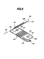
- FIG. 7 to 9 different temporally successive phases of such a folding process are shown, in which, in the exemplary embodiment shown, the second material layer 136b is folded over onto the first material layer 136a.
- the angle ⁇ which the main planes of the two material layers 136a, 136b enclose, is 180 ° (in the in Fig. 6 shown base body preform 158) is continuously reduced until this angle in the finished base 114 of the cell connector 112 (see Fig. 3 ) Is 0 ° and the second material layer 136b bears substantially flat against the first material layer 136a.
- the two layers of material 136a and 136b are arranged on the front side, that is to say along a fold line 138 extending in the transverse direction 128 of the cell connector 112, are integrally connected to each other, it is advantageous if the two layers of material 136a, 136b on the fold line 138 opposite end by an additional measure, for example by welding, are connected to unintentional release of the material layers 136a, 136b from each other, with refolding of Base 114, to prevent.
- the material layers 136a, 136b of the main body 114 are connected to one another by the one-piece connection along the fold line 138 by no further measures (ie in particular neither materially cohesive nor non-positive), in particular by no additional welding.
- the refolding is carried out geometrically such that the required current cross-section of the cell connector 112 is not or at least not significantly below.
- the cell connector 112 produced in this way is connected in the contact regions 116 and 118, preferably by material bonding, to a respective cell terminal 108 of an electrochemical cell 102.
- the contact point 150 of the voltage tap 144 is connected via a connecting line (not shown) to an evaluation unit (likewise not shown) of the electrochemical device 100.
- the illustrated second embodiment of a cell connector 112 for electrically connecting a first cell terminal 108a of a first electrochemical cell 102a and a second cell terminal 108b of a second electrochemical cell 102b differs from that described above in FIG Fig. 1 to 9 illustrated first embodiment in that the base body 114 of the cell connector 112 in the second embodiment not only a first voltage tap 144th includes, for example, connected to the second contact region 118, but additional another, second voltage tap 160, which is connected to the respective other contact region, ie in the present embodiment, with the first contact region 116.
- the second voltage tap 160 is preferably formed in only one of the material layers 136a, 136b of the main body 114 of the cell connector 112.
- the second voltage tap 160 is preferably formed in the first material layer 136a facing the cell terminals 108 of the electrochemical cells 102 to be connected to one another.
- first voltage tap 144 and the second voltage tap 160 are formed in the same material layer 136a of the main body 114 of the cell connector 112.
- the second voltage tap 160 comprises, for example, an initial section 162, which extends, for example, in the longitudinal direction 126 away from the first contact region 116 and is separated by a recess 164 from a likewise substantially in the longitudinal direction 126 extending lateral edge 166 of the first contact region 116, and a preferably in the transverse direction 128 of the cell connector 112 extending end portion 168, which is provided with a contact point 170.
- the end portion 168 and the beginning portion 162 of the second voltage tap 160 are interconnected via a curved central portion 172.
- the contact point 170 of the second voltage tap 160 can be connected to the evaluation unit of the electrochemical device 100 during the assembly of the cell connector 112 via a line (not shown).
- Fig. 10 shows a perspective view of the finished cell connector 112 of the second embodiment.
- the Fig. 11 to 13 show a main body preform 158, from which the cell connector according to Fig. 10 can be produced by a folding process, of the three successive phases in the Fig. 14 to 16 are shown.
- One in the Fig. 17 to 23 illustrated third embodiment of a cell connector 112 differs from the first two, in the Fig. 1 to 16 illustrated embodiments in that the fold line 138, along which the first material layer 136a and the second material layer 136b are integrally connected to each other, not parallel to the transverse direction 128 of the cell connector 112, but instead substantially parallel to the longitudinal direction 126 and thus substantially parallel to the connecting direction 110th the cell connector 112 runs.
- Fig. 17 shows a perspective view of the finished cell connector 112 according to the third embodiment.
- the Fig. 18 to 20 show a main body preform 158, from which the main body 114 according to Fig. 17 can be produced by a folding process, of the three successive phases in the Fig. 21 to 23 are shown.
- fold line 138 in this embodiment comprises a first portion 176 extending between first contact region 116 of first material layer 136a and first contact region 116 of second material layer 136b, and a second portion 178 extending between second contact region 118 of FIG the first material layer 136a and the second contact region 118 of the second material layer 136b.
- the two sections 176 and 178 of the fold line 138 are separated in this embodiment by an intermediate recess 180 from each other.
- the recess 180 in the region of the compensation region 124 of the cell connector 112 makes it possible for the adjacent compensation regions 124 of the first material layer 136a and the second material layer 136b to be formed complementary to one another (see in particular the side view of the main body preform 158 in FIG Fig. 19 ).
- the compensation area 124 not a plurality, but in each case only one wave crest 130 and not several, but in each case only one wave trough 132 on. Basically, however, the number of waves in the compensation area 124 is arbitrary, so that in the Fig. 17 to 23 illustrated third embodiment also with a larger number of waves and in the Fig. 1 to 16 illustrated embodiments of a cell connector 112 may also be provided with a smaller (or even greater) number of waves in the compensation area 124.
- a contact region 116, 118 having a smaller radius of curvature can also be combined with a fold line 138 running parallel to the longitudinal direction 126, and a contact region having a larger radius of curvature can in principle also be combined with a fold line 138 running parallel to the transverse direction 128 of the cell connector 112.
- the voltage taps 144 and 160 of the cell connector 112 in the in the Fig. 17 to 23 illustrated third embodiment not formed web-like, but form over the outer contour of the respective other material layer 136b projecting corner regions of the contact regions 116, 118 of a material layer 136a of the base body 114th
- the first voltage tap 144 and / or the second voltage tap 160 are arranged on the first material layer 136a, which in the mounted state of the cell connector 112 faces the cell terminals 108 of the electrochemical cells 102 to be connected to one another. It is particularly favorable if both voltage taps 144 and 160 are provided on the same material layer, preferably on the first material layer 136a.
- the contact points 150 of the voltage taps 144 and 160 are connected during assembly of the cell connector 112 via lines (not shown) to an evaluation unit (not shown) of the electrochemical device 100 in order to monitor the electrical potentials of the first contact region 116 and the second contact region 118 during operation Detect electrochemical device 100 and to be able to evaluate.
- a cell connector 112 For the production of the third embodiment of a cell connector 112 is first made of a starting material, for example of a sheet-like starting material, in the Fig. 18 to 20 shown base body preform 158 cut out, for example, punched out or cut out (for example by means of a laser).
- the two layers of material 136a and 136b lie in the same plane, along the later fold line 138, next to one another.
- the wave crests 130 and wave troughs 132 of the respective compensation regions 124 are introduced by suitable forming processes, in particular embossing or deep drawing operations.
- the passage openings 120 and 122 are introduced into the contact regions 116 and 118 of the material layers 136a and 136b, respectively, of the main body preform 158.
- the in Fig. 17 illustrated base body 114 of the cell connector 112 from the in Fig. 20 illustrated base body preform 158 produced by a Umfaltvorgang in which one of the material layers, for example, the second material layer 136b, is folded about the fold line 138 so that the trapped by the material layers 136a and 136b angle ⁇ of initially 180 ° to 0 ° reduced and the two material layers 136a, 136b finally abut substantially flat against each other.
- one of the material layers for example, the second material layer 136b
- the angle ⁇ enclosed by the material layers 136a, 136b is 135 ° in each case ( Fig. 21 ), 90 ° ( Fig. 22 ) or 45 ° ( Fig. 23 ).
- the distance of the free edges 182 of the material layers 136a, 136b from the fold line 138 is relatively small, in particular smaller than the total extension of the fold line 138 in the longitudinal direction 126 of the cell connector 112, however, such additional measures for connecting the two material layers 136a, 136b to one another can be dispensed with.
- the material layers 136a, 136b of the main body 114 of the cell connector 112 are therefore connected to one another, apart from the one-piece connection along the fold line 138, by no further measure (that is to say in particular neither materially cohesive nor force-fit).
- the finished base 114 according to Fig. 17 is then connected to the cell terminals 108 of the electrochemical cells 102 to be interconnected, preferably cohesively.
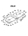
- One in the Fig. 24 to 31 illustrated fourth embodiment of a cell connector 112 differs from the third, in the Fig. 17 to 23 illustrated embodiment in that the second material layer 136b is not integrally formed, but along a dividing line 186 is divided into two partial material layers 184a and 184b, which in each case along mutually different fold lines 138a and 138b integrally connected to the first material layer 136a of the main body 114 are.
- the dividing line 186 and the two fold lines 138a and 138b preferably run essentially parallel to the longitudinal direction 126 and thus substantially parallel to the connecting direction 110 of the cell connector 112.
- Fig. 24 shows a perspective view of the finished cell connector 112 according to the fourth embodiment.
- Fig. 25 shows a top view of the finished cell connector 112 according to the fourth embodiment.
- Fig. 26 shows a side view of the finished cell connector 112 according to the fourth embodiment.
- the Fig. 27 and 28 show a main body preform 158, from which the main body 114 according to the FIGS. 24 to 26 can be produced by a folding process, of the three successive phases in the Fig. 29 to 31 are shown.
- the first fold line 138a in this embodiment includes a first portion 176a extending between the first contact region 116 of the first material layer 136a and a first part contact region 116a of the first part material layer 184a of the second material layer 136b, and a second part 178a, which extends between the second contact region 118 of the first material layer 136a and a second partial contact region 118a of the first partial material layer 184a of the second material layer 136b.
- the two sections 176a and 178a of the first fold line 138a are separated from each other in this embodiment by an intermediate recess 180a.
- the recess 180a in the region of the compensation region 124 of the cell connector 112 enables the adjacent compensation regions 124 of the first material layer 136a and the first partial material layer 184a of the second material layer 136b to be formed complementary to one another.
- the compensation area 124 does not have a plurality of but rather only one wave crest 130 and not a plurality of crests, but only one wave crest 132 in each case.
- the number of wave compensation areas waves of the compensation areas 124 Basically, the number of wave compensation areas waves of the compensation areas 124, however, arbitrary, so that in the Fig. 24 to 31 illustrated fourth embodiment may also be provided with a larger number of waves.
- the second fold line 138b in this embodiment comprises a first section 176b which extends between the first contact region 116 of the first material layer 136a and a first partial contact region 116b of the second partial material layer 184b of the second material layer 136b, and a second section 178b which extends between the second contact region 118 of the first material layer 136a and a second partial contact region 118b of the second partial material layer 184b of the second material layer 136b.
- the two portions 176b and 178b of the second fold line 138b are separated in this embodiment by an intermediate recess 180b.
- the recess 180b in the region of the compensation region 124 of the cell connector 112 enables the adjacent compensation regions 124 of the first material layer 136a and the second partial material layer 184b of the second material layer 136b to be formed complementary to one another.
- the dividing line 186 of the second material layer 136b passes through the center 140 of the first contact region 116 and the center 142 of the second contact region 118 of the second material layer 136b, the first through-hole 120 of the first contact region 116 and the second through-hole form 122 of the second contact region 118 of the second material layer 136b in the main body preform 158 no holes with a closed edge, but, for example, substantially semicircular recesses 188 at the free edges 190 of the two partial material layers 184a, 184b, which of the respective fold line 138a and 138b are opposite.
- a cell connector 112 For the production of the fourth embodiment of a cell connector 112 is first made of a starting material, for example of a sheet-like starting material, in the Fig. 27 and 28 shown base body preform 158 cut out, for example, punched out or cut out (for example by means of a laser).
- the first material layer 136a and the two partial material layers 184a, 184b of the second material layer 136b lie side by side in the same plane along the later fold lines 138a and 138b.
- the wave crests 130 and wave troughs 132 of the respective compensation regions 124 are introduced by suitable forming processes, in particular embossing or deep drawing processes.
- the passage openings 120 and 122 are introduced into the contact regions 116 and 118 of the material layer 136a of the main body preform 158.
- FIGS. 24 to 26 illustrated base body 114 of the cell connector 112 from the in the Fig. 27 and 28 illustrated base body preform 158 produced by a Umfaltvorgang, in which the two partial material layers 184a, 184b of the second material layer 136b are folded around the respectively associated fold line 138a and 138b so that the material layer of the 136a on the one hand and the partial material layers 184a, 184b, on the other hand, reduces included angles ⁇ from initially 180 ° to 0 °, and in the end the first material layer 136a and the two partial material layers 184a, 184b of the second material layer 136b substantially abut one another flatly.
- the angle ⁇ enclosed by the first material layer 136a on the one hand and the partial material layers 184a or 184b on the other hand is 135 ° in each case ( Fig. 29 ), 90 ° ( Fig. 30 ) or 45 ° ( Fig. 31 ).
- the free edges 190 of the partial material layers 184a, 184b of the second material layer 136 abut one another along the dividing line 186. or facing each other with close proximity.
- the material layer 136a and the partial material layers 184a, 184b may be connected to one another after the unfolding process by further measures, for example by welding and / or by mechanical jamming, in addition to the one-piece connection along the fold lines 138a, 138b to avoid unintentional re-folding of the body 114.
- the distance of the free edges 190 of the partial material layers 184a and 184b of the respective fold line 138a and 138b is relatively small, in particular smaller than the entire extent of the Folding lines 138a and 138b in the longitudinal direction 126 of the cell connector 112, however, such additional measures for connecting the material layer 136a with the partial material layers 184a and 184b with each other can be dispensed with.
- the material layer 136a and the partial material layers 184a, 184b of the main body 114 of the cell connector 112 are therefore connected to one another, apart from the one-piece connection along the fold lines 138a and 138b, by no further measure (that is to say in particular neither materially cohesive nor force-fit).
- the finished base 114 according to the FIGS. 24 to 26 is then connected to the cell terminals 108 of the electrochemical cells 102 to be interconnected, preferably cohesively.
- Illustrated fifth embodiment of a cell connector 112 differs from the third, in the Fig. 17 to 23 illustrated embodiment in that the first material layer 136a is integrally connected not only with the second material layer 136b along a fold line, but along a first fold line 138a integral with the second material layer 136b and along a second fold line 138b integral with a third material layer 136c of the main body 114th connected is.
- the two fold lines 138a and 138b preferably run essentially parallel to the longitudinal direction 126 and thus substantially parallel to the connecting direction 110 of the cell connector 112.
- Fig. 32 shows a perspective view of the finished cell connector 112 according to the fifth embodiment, which thus comprises three layers of material 136a, 136b and 136c.
- Fig. 33 shows a top view of the finished cell connector 112 according to the fifth embodiment.
- Fig. 34 shows a side view of the finished cell connector 112 according to the fifth embodiment.
- the Fig. 35 and 36 show a main body preform 158, from which the main body 114 according to the FIGS. 32 to 34 can be produced by a folding process, of the three successive phases in the FIGS. 37 to 39 are shown.
- the first fold line 138a in this embodiment comprises a first section 176a which extends between the first contact region 116 of the first material layer 136a and the first contact region 116 of the second material layer 136b, and a second section 178a which extends between the second contact region 118 the first material layer 136a and the second contact region 118 of the second material layer 136b.
- the two sections 176a and 178a of the first fold line 138a are separated from each other in this embodiment by an intermediate recess 180a.
- the recess 180a in the region of the compensation region 124 of the cell connector 112 enables the adjacent compensation regions 124 of the first material layer 136a and the second material layer 136b to be formed complementary to one another.
- the compensation area 124 does not have a plurality of but rather only one wave crest 130 and not a plurality of crests, but only one wave crest 132 in each case.
- the number of waves of the compensation areas 124 is arbitrary, so that in the FIGS. 32 to 39 illustrated fifth embodiment may also be provided with a larger number of waves.
- the second fold line 138b in this embodiment comprises a first section 176b which extends between the first contact region 116 of the first material layer 136a and the first contact region 116 of the third material layer 136c, and a second section 178b which extends between the second contact region 118 of the first material layer 136a and the second contact region 118 of the third material layer 136c.
- the two portions 176b and 178b of the second fold line 138b are separated in this embodiment by an intermediate recess 180b.
- the recess 180b in the region of the compensation region 124 of the cell connector 112 enables the adjacent compensation regions 124 of the first material layer 136a and the third material layer 136c to be formed complementary to one another.
- a cell connector 112 For producing the fifth embodiment of a cell connector 112 is first made of a starting material, for example of a sheet-like starting material, in the Fig. 35 and 36 shown base body preform 158 cut out, for example, punched out or cut out (for example by means of a laser).
- the first material layer 136a, the second material layer 136b, and the third material layer 136c are juxtaposed in the same plane along the later fold lines 138a and 138b.
- the wave crests 130 and wave troughs 132 of the respective compensation regions 124 are introduced by suitable forming processes, in particular embossing or deep drawing operations.
- the passage openings 120 and 122 are introduced into the contact regions 116 and 118 of the material layers 136a, 136b and 136c of the main body preform 158.
- FIGS. 32 to 34 illustrated base body 114 of the cell connector 112 from the in the Fig. 35 and 36 illustrated base body preform 158 produced by a Umfaltvorgang, in which the second material layer 136b and the third layer of material 136c to the respectively associated fold line 138a and 138b are folded so that of the material layer 136a on the one hand and the material layers 136b and 136c on the other enclosed angle ⁇ reduced from 180 ° initially to 0 ° and the first material layer 136a and the second material layer 136b and the third material layer 136c finally abut substantially flat against each other.
- the angle ⁇ enclosed by the first material layer 136a on the one hand and the second material layer 136b or the third material layer 136c on the other hand is 135 ° in each case ( Fig. 37 ), 90 ° ( Fig. 38 ) or 45 ° ( Fig. 39 ).
- the distance of the free edges 190 of the material layers 136b and 136c from the respective fold line 138a and 138b, respectively, is relatively small, in particular smaller than the total extent of the fold lines 138a and 138b in the longitudinal direction 126 of the cell connector 112,
- additional measures for connecting the material layer 136a with the two other material layers 136b and 136c can be dispensed with.
- the material layer 136a and the material layers 136b and 136c of the main body 114 of the cell connector 112 are therefore connected to one another, apart from the one-piece connection along the fold lines 138a and 138b, by no further measure (that is, in particular, neither materially cohesive nor non-positive).
- the finished base 114 according to the FIGS. 32 to 34 is then connected to the cell terminals 108 of the electrochemical cells 102 to be interconnected, preferably cohesively.
- FIGS. 32 to 39 illustrated fifth embodiment of a cell connector 112 in terms of structure, function and method of manufacture with in the Fig. 17 to 23 illustrated third embodiment, the above description of which reference is made.
Landscapes
- Chemical & Material Sciences (AREA)
- Chemical Kinetics & Catalysis (AREA)
- Electrochemistry (AREA)
- General Chemical & Material Sciences (AREA)
- Engineering & Computer Science (AREA)
- Materials Engineering (AREA)
- Manufacturing & Machinery (AREA)
- Inorganic Chemistry (AREA)
- Connection Of Batteries Or Terminals (AREA)
Description
Die vorliegende Erfindung betrifft einen Zellverbinder zum elektrisch leitfähigen Verbinden eines ersten Zellterminals einer ersten elektrochemischen Zelle und eines zweiten Zellterminals einer zweiten elektrochemischen Zelle einer elektrochemischen Vorrichtung, wobei der Zellverbinder einen ersten Kontaktbereich zum Verbinden mit dem ersten Zellterminal und einen zweiten Kontaktbereich zum Verbinden mit dem zweiten Zellterminal umfasst.The present invention relates to a cell connector for electrically connecting a first cell terminal of a first electrochemical cell and a second cell terminal of a second electrochemical cell of an electrochemical device, wherein the cell connector has a first contact area for connecting to the first cell terminal and a second contact area for connecting to the second Cell terminal includes.
Solche elektrochemischen Vorrichtungen können insbesondere als elektrische Akkumulatoren, beispielsweise als Lithium-Ionen-Akkumulatoren, ausgebildet sein.Such electrochemical devices may in particular be designed as electric accumulators, for example as lithium-ion accumulators.
Bei einem Lithium-Ionen-Akkumulator beträgt die Spannungsdifferenz zwischen den beiden Zellterminals (Polen) einer einzelnen Akkumulatorzelle ungefähr 3,6 V. Um ein für viele Anwendungen, beispielsweise in der Automobil-Antriebstechnik, benötigtes höheres Spannungsniveau von beispielsweise ungefähr 360 V zu erhalten, müssen viele solcher Akkumulatorzellen (beispielsweise ungefähr 100) elektrisch in Reihe geschaltet werden.In a lithium-ion battery, the voltage difference between the two cell terminals (poles) of a single battery cell is about 3.6 V. In order to obtain a higher voltage level of, for example, about 360 V required for many applications, for example in automotive propulsion technology, For example, many such accumulator cells (for example, about 100) must be electrically connected in series.
Die Akkumulatorzellen oder allgemein elektrochemischen Zellen können dabei zu Modulen zusammengefasst werden, welche jeweils mehrere solcher elektrochemischer Zellen enthalten, wobei die Einbaurichtung nebeneinander angeordneter Zellen alterniert, so dass positive und negative Zellterminals abwechselnd nebeneinander liegen.The accumulator cells or generally electrochemical cells can be combined into modules, each of which contains a plurality of such electrochemical cells, wherein the installation direction of juxtaposed cells alternates, so that positive and negative cell terminals are adjacent to each other.
Diese einander benachbarten Zellterminals entgegensetzter Polarität werden für die Reihenschaltung der Zellen mittels jeweils eines Zellverbinders direkt miteinander verbunden.These mutually adjacent cell terminals of opposite polarity are connected directly to each other for the series connection of the cells by means of a respective cell connector.
Durch unterschiedliche thermische Dehnungen der Anordnung elektrochemischer Zellen und des Zellverbinders (aufgrund von Temperaturunterschieden und/oder aufgrund von Unterschieden in den jeweiligen thermischen Ausdehnungskoeffizienten) treten auf die Zellterminals einwirkende Kräfte auf, die von dem Zellverbinder übertragen werden.Due to different thermal expansions of the arrangement of electrochemical cells and of the cell connector (due to temperature differences and / or due to differences in the respective coefficients of thermal expansion), forces acting on the cell terminals occur, which are transmitted by the cell connector.
Die
Der vorliegenden Erfindung liegt die Aufgabe zugrunde, einen Zellverbinder für eine elektrochemische Vorrichtung der eingangs genannten Art zu schaffen, welcher eine große Relativverschiebung zwischen dem ersten Kontaktbereich und dem zweiten Kontaktbereich bereits bei Einwirkung von nur geringen Verformungskräften ermöglicht.The present invention has for its object to provide a cell connector for an electrochemical device of the type mentioned, which allows a large relative displacement between the first contact region and the second contact region already under the action of only low deformation forces.
Diese Aufgabe wird durch einen Zellverbinder nach Anspruch 1 gelöst.This object is achieved by a cell connector according to
Durch die Verwendung eines mehrlagigen Zellverbinders wird ein niedrigeres axiales Flächenmoment genutzt als bei der Verwendung eines einlagigen Zellverbinders.By using a multi-layer cell connector, a lower axial momentum is used than when using a single-layer cell connector.
Dadurch, dass mindestens zwei Materiallagen des mehrlagigen Grundkörpers, vorzugsweise alle Materiallagen des mehrlagigen Grundkörpers, längs einer oder mehrerer Faltlinien einstückig miteinander verbunden sind, wird eine einfache und zuverlässige elektrische Kontaktierung und mechanische Verbindung zwischen mehreren Lagen des Grundkörpers geschaffen, ohne dass hierfür ein zusätzlicher aufwendiger Fügeprozess, beispielsweise ein Schweißvorgang, insbesondere ein Laserschweißvorgang, erforderlich ist.Characterized in that at least two layers of material of the multilayer main body, preferably all material layers of the multilayer main body along one or more fold lines are integrally connected to each other, a simple and reliable electrical contact and mechanical connection between multiple layers of the body is created without requiring an additional costly Joining process, such as a welding process, in particular a laser welding process is required.
Somit wird durch Umfalten ein Zellverbinder hergestellt, der beispielsweise in einem Folgeverbundwerkzeug herstellbar ist und dessen Einzellagen nicht durch Verschweißungen oder andere Verbindungsmechanismen miteinander verbunden werden müssen.Thus, by folding over, a cell connector is produced which can be produced, for example, in a follow-on composite tool and whose individual layers do not have to be connected to one another by welding or other connection mechanisms.
Die Umfaltung kann sich je nach Geometrie des Zellverbinders bzw. je nach den Anforderungen an den Zellverbinder seitlich am Zellverbinder oder stirnseitig am Zellverbinder befinden.Depending on the geometry of the cell connector or, depending on the requirements of the cell connector, the refolding can be located laterally on the cell connector or on the front side of the cell connector.
Wenn sich die Faltlinie stirnseitig an dem Zellverbinder befindet, kann auf der gegenüberliegenden Seite eine zusätzliche Verbindung der Lagen durch eine weitere Verbindungsmaßnahme, beispielsweise durch eine Verschweißung, erfolgen.If the fold line is located on the end face of the cell connector, on the opposite side, an additional connection of the layers by another connection measure, for example by a weld, take place.
Die Umfaltung längs der Faltlinie ist geometrisch derart auszuführen, dass der für den Stromdurchgang durch den Zellverbinder erforderliche Stromquerschnitt nicht unterschritten wird.The refolding along the fold line is geometrically designed such that the current cross section required for the passage of current through the cell connector is not undershot.
Mindestens zwei Materiallagen, insbesondere alle Materiallagen, des Grundkörpers liegen, insbesondere im ersten Kontaktbereich und/oder im zweiten Kontaktbereich des Zellverbinders, im Wesentlichen flächig aneinander an.At least two layers of material, in particular all layers of material, of the basic body lie against one another, in particular in the first contact area and / or in the second contact area of the cell connector, substantially flat.
Bei einer besonderen Ausgestaltung der Erfindung ist vorgesehen, dass mindestens eine Faltlinie zumindest abschnittsweise quer, vorzugsweise im Wesentlichen senkrecht, zu einer Verbindungsrichtung, welche ein Zentrum des ersten Kontaktbereichs und ein Zentrum des zweiten Kontaktbereichs miteinander verbindet, verläuft.In a particular embodiment of the invention, it is provided that at least one fold line extends at least in sections transversely, preferably substantially perpendicular, to a connection direction which connects a center of the first contact region and a center of the second contact region.
Besonders einfach herstellbar ist der erfindungsgemäße Zellverbinder, wenn der Grundkörper keine Schweißverbindungen und/oder außer der Einstückigkeit von Materiallagen keine anderen Verbindungsmechanismen zwischen den Materiallagen des Grundkörpers aufweist.The cell connector according to the invention is particularly easy to produce if the base body has no welded connections and / or no other connection mechanisms between the material layers of the main body except for the integral nature of material layers.
Ferner ist es günstig, wenn der Grundkörper keine stoffschlüssigen Verbindungen zwischen den Materiallagen des Grundkörpers aufweist.Furthermore, it is favorable if the main body has no material connections between the material layers of the main body.
Der Grundkörper des Zellverbinders umfasst vorzugsweise den ersten Kontaktbereich und/oder den zweiten Kontaktbereich des Zellverbinders.The main body of the cell connector preferably comprises the first contact area and / or the second contact area of the cell connector.
Der Grundkörper des Zellverbinders ist vorzugsweise einstückig ausgebildet.The main body of the cell connector is preferably formed in one piece.
Ferner kann vorgesehen sein, dass mindestens eine Faltlinie im Wesentlichen vollständig quer, insbesondere im Wesentlichen senkrecht, zu der Verbindungsrichtung verläuft.Furthermore, it can be provided that at least one fold line runs essentially completely transversely, in particular substantially perpendicular, to the connection direction.
Zumindest ein Abschnitt von mindestens einer Faltlinie kann längs eines seitlichen Randes des ersten Kontaktbereichs oder des zweiten Kontaktbereichs verlaufen.At least a portion of at least one fold line may run along a lateral edge of the first contact area or the second contact area.
Ferner kann bei einer besonderen Ausgestaltung des erfindungsgemäßen Zellverbinders vorgesehen sein, dass mindestens eine Faltlinie zumindest abschnittsweise, vorzugsweise im Wesentlichen vollständig, im Wesentlichen parallel zu einer Verbindungsrichtung, welche ein Zentrum des ersten Kontaktbereichs und ein Zentrum des zweiten Kontaktbereichs miteinander verbindet, verläuft.Furthermore, it can be provided in a particular embodiment of the cell connector according to the invention that at least one fold line, at least partially, preferably substantially completely, substantially parallel to a connection direction, which connects a center of the first contact region and a center of the second contact region, extends.
Ferner kann vorgesehen sein, dass mindestens eine Faltlinie in einem ersten Abschnitt längs eines seitlichen Randes des ersten Kontaktbereichs und in einem zweiten Abschnitt längs eines seitlichen Randes des zweiten Kontaktbereichs verläuft.Furthermore, it can be provided that at least one fold line extends in a first section along a lateral edge of the first contact region and in a second section along a lateral edge of the second contact region.
In diesem Fall kann insbesondere die Faltlinie zwischen dem ersten Abschnitt und dem zweiten Abschnitt durch eine Ausnehmung unterbrochen sein.In this case, in particular, the fold line between the first portion and the second portion may be interrupted by a recess.
Bei einer besonderen Ausgestaltung des erfindungsgemäßen Zellverbinders kann vorgesehen sein, dass mindestens eine der Materiallagen des Grundkörpers mindestens zwei Teil-Materiallagen umfasst, die längs voneinander verschiedener Faltlinien einstückig mit einer anderen Materiallage verbunden sind. Bei einer solchen Ausführungsform ist also mindestens eine Materiallage des Grundkörpers nicht einteilig ausgebildet, sondern in mindestens zwei Teil-Materiallagen unterteilt.In a particular embodiment of the cell connector according to the invention, it can be provided that at least one of the material layers of the base body comprises at least two partial material layers, which are integrally connected to a different material layer along mutually different fold lines. In such an embodiment, therefore, at least one material layer of the main body is not formed in one piece, but divided into at least two partial material layers.
Dabei verläuft die Trennlinie zwischen den zwei Teil-Materiallagen vorzugsweise im Wesentlichen parallel zu einer Verbindungsrichtung, welche ein Zentrum des ersten Kontaktbereichs und ein Zentrum des zweiten Kontaktbereichs miteinander verbindet.In this case, the dividing line between the two partial material layers preferably runs essentially parallel to a connecting direction, which connects a center of the first contact region and a center of the second contact region to one another.
Mindestens zwei Teil-Materiallagen der geteilten Materiallage des Grundkörpers können dabei beide über voneinander verschiedene Faltlinien einstückig mit derselben anderen Materiallage des Grundkörpers verbunden sein.At least two partial material layers of the divided material layer of the basic body can both be connected in one piece to the same other material layer of the basic body via fold lines which are different from one another.
Alternativ hierzu ist auch denkbar, dass zwei Teil-Materiallagen der geteilten Materiallage des Grundkörpers längs voneinander verschiedener Faltlinien mit zwei voneinander verschiedenen anderen Materiallagen des Grundkörpers verbunden sind.As an alternative to this, it is also conceivable that two partial material layers of the divided material layer of the main body are connected along fold lines which are different from one another with two mutually different material layers of the main body.
Die voneinander verschiedenen Faltlinien, längs welcher die mindestens zwei Teil-Materiallagen einstückig mit einer anderen Materiallage verbunden sind, sind vorzugsweise auf einander gegenüberliegenden Seiten der betreffenden geteilten Materiallage angeordnet.The mutually different fold lines, along which the at least two partial material layers are integrally connected to another material layer, are preferably arranged on opposite sides of the respective divided material layer.
Bei einer besonderen Ausgestaltung des erfindungsgemäßen Zellverbinders kann ferner vorgesehen sein, dass mindestens eine der Materiallagen des Grundkörpers längs voneinander verschiedener Faltlinien einstückig mit zwei anderen Materiallagen verbunden ist. In diesem Fall weist der Grundkörper des Zellverbinders also mindestens drei einstückig miteinander verbundene Materiallagen auf, was zur Folge hat, dass der elektrische Widerstand des Grundkörpers vermindert wird. Bei gleicher durch den Zellverbinder fließenden Stromstärke heizt sich der Zellverbinder daher weniger auf. Umgekehrt steigt bei gleicher Erwärmung des Zellverbinders die Stromstärke, welche der Zellverbinder tragen kann.In a particular embodiment of the cell connector according to the invention, it may further be provided that at least one of the material layers of the base body is connected integrally with two other material layers along mutually different fold lines. In this case, the main body of the cell connector so at least three integrally connected material layers, which has the consequence that the electrical resistance of the body is reduced. With the same current flowing through the cell connector, the cell connector therefore heats up less. Conversely, with the same heating of the cell connector, the current strength which the cell connector can carry increases.
Grundsätzlich können auch mehr als drei Materiallagen des Zellverbinders jeweils über Faltlinien einstückig miteinander verbunden sein, insbesondere in einer ziehharmonikaartigen Faltung.In principle, more than three layers of material of the cell connector can also be integrally connected to one another via fold lines, in particular in a concertina-like folding.
Die voneinander verschiedenen Faltlinien, längs welcher die mindestens eine Materiallage des Grundkörpers mit zwei anderen Materiallagen des Grundkörpers verbunden ist, sind vorzugsweise auf einander gegenüberliegenden Seiten der betreffenden Materiallage angeordnet.The mutually different fold lines, along which the at least one material layer of the base body is connected to two other material layers of the base body, are preferably arranged on opposite sides of the respective material layer.
Um eine besondere zuverlässige und betriebssichere Verbindung der Zellterminals zu ermöglichen, ist bei der Erfindung vorgesehen, dass der Grundkörper des Zellverbinders einen elastisch und/oder plastisch verformbaren Kompensationsbereich umfasst, der den ersten Kontaktbereich und den zweiten Kontaktbereich miteinander verbindet und eine Bewegung dieser Kontaktbereiche relativ zueinander ermöglicht.In order to enable a special reliable and reliable connection of the cell terminals, it is provided in the invention that the main body of the cell connector comprises an elastically and / or plastically deformable compensation area, which connects the first contact area and the second contact area and a movement of these contact areas relative to each other allows.
Durch diese Möglichkeit zur Bewegung der beiden Kontaktabschnitte des Zellverbinders relativ zueinander dient der elastisch und/oder plastisch verformbare Kompensationsbereich zur zumindest teilweisen Kompensation
- a) einer Differenz zwischen einer Längsdehnung des Zellverbinders einerseits und einer Änderung des Abstands zwischen den Längsachsen der durch den Zellverbinder miteinander verbundenen Zellterminals andererseits und/oder
- b) einer Differenz zwischen einer Längsdehnung der ersten elektrochemischen Zelle einerseits und einer Längsdehnung der zweiten elektrochemischen Zelle andererseits.
- a) a difference between a longitudinal expansion of the cell connector on the one hand and a change in the distance between the longitudinal axes of the cell terminals connected by the cell connector on the other hand and / or
- b) a difference between a longitudinal expansion of the first electrochemical cell on the one hand and a longitudinal expansion of the second electrochemical cell on the other.
Ergänzend hierzu kann der elastisch und/oder plastisch verformbare Kompensationsbereich auch zur zumindest teilweisen Kompensation von Unterschieden in den Positionen der miteinander zu verbindenden Zellterminals, die auf Fertigungstoleranzen beruhen, insbesondere in der Axialrichtung der elektrochemischen Zellen, dienen.In addition thereto, the elastically and / or plastically deformable compensation region can also be used for at least partial compensation of differences in the positions of the cell terminals to be connected to one another, which are based on manufacturing tolerances, in particular in the axial direction of the electrochemical cells.
Um die gewünschte Relativbewegung zwischen den beiden Kontaktabschnitten des Zellverbinders zu ermöglichen, ist der Kompensationsbereich vorzugsweise mit einer Profilierung, insbesondere mit einer Wellenstruktur und/oder einer Zickzackstruktur und/oder einer Sickenstruktur, versehen.In order to enable the desired relative movement between the two contact sections of the cell connector, the compensation region is preferably provided with a profiling, in particular with a corrugated structure and / or a zigzag structure and / or a bead structure.
Insbesondere kann vorgesehen sein, dass der Kompensationsbereich des Zellverbinders mindestens eine quer zu einer Verbindungsrichtung, welche ein Zentrum des ersten Kontaktbereichs und ein Zentrum des zweiten Kontaktbereichs miteinander verbindet, verlaufende Kompensationswelle, Kompensationssicke oder Kompensationsknicklinie aufweist.In particular, it can be provided that the compensation region of the cell connector has at least one compensation wave, compensation bead or compensation bend line extending transversely to a connection direction which connects a center of the first contact region and a center of the second contact region.
Der Kompensationsbereich ist nicht in nur einer der Materiallagen des Grundkörpers, sondern in zwei oder mehr aufeinanderliegenden Materiallagen ausgebildet.The compensation area is not formed in only one of the material layers of the basic body, but in two or more superposed material layers.
Um in einfacher Weise das elektrische Potential an dem Zellverbinder erfassen und auswerten zu können, ist es von Vorteil, wenn der Grundkörper des Zellverbinders mindestens einen Spannungsabgriff umfasst.In order to be able to detect and evaluate the electrical potential at the cell connector in a simple manner, it is advantageous if the main body of the cell connector comprises at least one voltage tap.
An diesen Spannungsabgriff ist über eine geeignete elektrische Leitung eine Auswerteeinheit der elektrochemischen Vorrichtung anschließbar.An evaluation unit of the electrochemical device can be connected to this voltage tap via a suitable electrical line.
Mindestens ein solcher Spannungsabgriff ist vorzugsweise stegförmig ausgebildet.At least one such voltage tap is preferably web-shaped.
Um das elektrische Potential am ersten Kontaktbereich und am zweiten Kontaktbereich des Zellverbinders getrennt erfassen und auswerten zu können, ist es günstig, wenn der Grundkörper des Zellverbinders mindestens zwei Spannungsabgriffe umfasst, wobei ein Spannungsabgriff mit dem ersten Kontaktbereich und ein weiterer Spannungsabgriff mit dem zweiten Kontaktbereich verbunden ist.In order to separately detect and evaluate the electrical potential at the first contact region and at the second contact region of the cell connector, it is favorable if the main body of the cell connector comprises at least two voltage taps, wherein one voltage tap is connected to the first contact region and another voltage tap is connected to the second contact region is.
Bei einer bevorzugten Ausgestaltung des erfindungsgemäßen Zellverbinders ist vorgesehen, dass mindestens ein Spannungsabgriff des Zellverbinders in nur einer Materiallage des Grundkörpers des Zellverbinders ausgebildet ist.In a preferred embodiment of the cell connector according to the invention, it is provided that at least one voltage tap of the cell connector is formed in only one material layer of the main body of the cell connector.
Vorzugsweise sind alle Spannungsabgriffe des Zellverbinders jeweils in nur einer Materiallage des Grundkörpers des Zellverbinders ausgebildet.Preferably, all voltage taps of the cell connector are each formed in only one material layer of the main body of the cell connector.
Besonders günstig ist es, wenn mehrere, vorzugsweise alle, Spannungsabgriffe des Zellverbinders in derselben Materiallage des Grundkörpers des Zellverbinders ausgebildet sind.It is particularly favorable if several, preferably all, voltage taps of the cell connector are formed in the same material layer of the main body of the cell connector.
Die Ausdehnung des Grundkörpers des Zellverbinders ist vorzugsweise in einer zur Verbindungsrichtung des Zellverbinders parallelen Längsrichtung des Zellverbinders größer als in einer zur Längsrichtung des Zellverbinders und zur Axialrichtung der mittels des Zellverbinders miteinander verbundenen elektrochemischen Zellen senkrechten Querrichtung des Zellverbinders.The extension of the main body of the cell connector is preferably greater in a longitudinal direction of the cell connector parallel to the direction of connection of the cell connector than in a transverse direction of the cell connector perpendicular to the longitudinal direction of the cell connector and to the axial direction of the electrochemical cells interconnected by the cell connector.
Die elektrochemische Vorrichtung, in welcher der Zellverbinder eingesetzt wird, kann insbesondere als ein Akkumulator, beispielsweise als ein Lithium-Ionen-Akkumulator, ausgebildet sein.The electrochemical device in which the cell connector is used may, in particular, be designed as an accumulator, for example as a lithium-ion accumulator.
Wenn die erfindungsgemäße elektrochemische Vorrichtung als ein Akkumulator ausgebildet ist, eignet sie sich insbesondere als eine hochbelastbare Energiequelle, beispielsweise für den Antrieb von Kraftfahrzeugen.If the electrochemical device according to the invention is designed as an accumulator, it is suitable in particular as a heavy-duty energy source, for example for the propulsion of motor vehicles.
Die vorliegende Erfindung betrifft ferner ein Verfahren zum Herstellen eines Zellverbinders, der einen ersten Kontaktbereich zum Verbinden mit einem ersten Zellterminal einer ersten elektrochemischen Zelle und einen zweiten Kontaktbereich zum Verbinden mit einem zweiten Zellterminal einer zweiten elektrochemischen Zelle umfasst.The present invention further relates to a method of manufacturing a cell connector comprising a first contact area for connecting to a first cell terminal of a first electrochemical cell and a second contact area for connecting to a second cell terminal of a second electrochemical cell.
Der vorliegenden Erfindung liegt die weitere Aufgabe zugrunde, ein solches Verfahren zu schaffen, durch welches ein Zellverbinder hergestellt wird, der eine zuverlässige und betriebssichere Verbindung der Zellterminals ermöglicht.The present invention has the further object of providing such a method by which a cell connector is produced, which allows a reliable and reliable connection of the cell terminals.
Diese Aufgabe wird erfindungsgemäß durch ein Verfahren nach Anspruch 15 gelöst.This object is achieved by a method according to
Weitere Merkmale und Vorteile der Erfindung sind Gegenstand der nachfolgenden Beschreibung und der zeichnerischen Darstellung von Ausführungsbeispielen.Further features and advantages of the invention are the subject of the following description and the drawings of exemplary embodiments.
In den Zeichnungen zeigen:
- Fig. 1
- einen schematischen Längsschnitt durch einen Zellverbinder und jeweils einen Teil der beiden elektrochemischen Zellen, die mittels des Zellverbinders miteinander verbunden sind, wobei der Zellverbinder einen Grundkörper aus zwei Materiallagen umfasst, die längs einer Faltlinie einstückig miteinander verbunden sind;
- Fig. 2
- einen schematischen Schnitt durch den Grundkörper des Zellverbinders aus
Fig. 1 , ohne die durch den Zellverbinder miteinander verbundenen elektrochemischen Zellen; - Fig. 3
- eine schematische perspektivische Darstellung des Zellverbinders aus den
Fig. 1 und 2 ; - Fig. 4
- eine schematische Draufsicht auf eine Grundkörper-Vorform des Zellverbinders aus den
Fig. 1 bis 3 , aus welcher der Grundkörper durch Faltung gebildet wird; - Fig. 5
- eine schematische Seitenansicht der Grundkörper-Vorform aus
Fig. 4 , mit der Blickrichtung in Richtung des Pfeiles 5 inFig. 4 ; - Fig. 6
- eine schematische perspektivische Darstellung der Grundkörper-Vorform aus den
Fig. 4 und5 ; - Fig. 7 bis 9
- schematische perspektivische Darstellungen der Grundkörper-Vorform aus
Fig. 6 in drei aufeinanderfolgenden Phasen eines Faltvorgangs, durch den der Zellverbinder-Grundkörper gemäßFig. 3 aus der Grundkörper-Vorform gemäßFig. 6 gebildet wird; - Fig. 10
- eine schematische perspektivische Darstellung einer zweiten Ausführungsform eines Zellverbinders mit einem Grundkörper, der statt nur eines stegförmigen Spannungsabgriffs zwei stegförmige Spannungsabgriffe umfasst, welche jeweils einem Kontaktbereich des Zellverbinders zugeordnet sind;
- Fig. 11
- eine schematische Draufsicht auf eine Grundkörper-Vorform, aus welcher der Grundkörper des Zellverbinders aus
Fig. 10 durch einen Faltvorgang gebildet wird; - Fig. 12
- eine schematische Seitenansicht der Grundkörper-Vorform aus
Fig. 11 , mit der Blickrichtung inRichtung des Pfeiles 12 inFig. 11 ; - Fig. 13
- eine schematische perspektivische Darstellung der Grundkörper-Vorform aus den
Fig. 11 und 12 ; - Fig. 14 bis 16
- schematische perspektivische Darstellungen der Grundkörper-Vorform aus den
Fig. 11 in drei aufeinanderfolgenden Phasen eines Faltvorgangs, durch welchen der Zellverbinder-Grundkörper gemäßbis 13Fig. 10 aus der Grundkörper-Vorform gemäßFig. 13 gebildet wird; - Fig. 17
- eine schematische perspektivische Darstellung einer dritten Ausführungsform eines Zellverbinders mit einem Grundkörper, welcher durch Faltung längs einer parallel zu einer Verbindungsrichtung des Zellverbinders verlaufenden Faltlinie aus einer Grundkörper-Vorform gebildet wird;
- Fig. 18
- eine schematische Draufsicht auf eine Grundkörper-Vorform des Zellverbinders aus
Fig. 17 ; - Fig. 19
- eine schematische Seitenansicht der Grundkörper-Vorform aus
Fig. 18 , mit der Blickrichtung inRichtung des Pfeiles 19 inFig. 18 ; - Fig. 20
- eine schematische perspektivische Darstellung der Grundkörper-Vorform aus den
Fig. 18 und 19 ; - Fig. 21 bis 23
- schematische perspektivische Darstellungen der Grundkörper-Vorform aus
Fig. 20 in drei aufeinanderfolgenden Phasen eines Faltvorgangs, durch welchen der Zellverbinder-Grundkörper gemäßFig. 17 aus der Grundkörper-Vorform gemäßFig. 20 gebildet wird; - Fig. 24
- eine schematische perspektivische Darstellung einer vierten Ausführungsform eines Zellverbinders mit einem Grundkörper, welcher der eine geteilte Materiallage umfasst, welche ihrerseits mindestens zwei Teil-Materiallagen umfasst, die längs voneinander verschiedener Faltlinien einstückig mit einer anderen Materiallage des Grundkörpers verbunden sind;
- Fig. 25
- eine schematische Draufsicht von oben auf den Zellverbinder aus
Fig. 24 ; - Fig. 26
- eine schematische Seitenansicht des Zellverbinders aus den
Fig. 24 undFig. 25 , mit der Blickrichtung inRichtung des Pfeiles 26 inFig. 25 ; - Fig. 27
- eine schematische Draufsicht auf eine Grundkörper-Vorform des Zellverbinders aus
Fig. 24 ; - Fig. 28
- eine schematische perspektivische Darstellung der Grundkörper-Vorform aus
Fig. 27 ; - Fig. 29 bis 31
- schematische perspektivische Darstellungen der Grundkörper-Vorform aus
Fig. 28 in drei aufeinanderfolgenden Phasen eines Faltvorgangs, durch welchen der Zellverbinder-Grundkörper gemäßFig. 24 aus der Grundkörper-Vorform gemäßFig. 28 gebildet wird; - Fig. 32
- eine schematische perspektivische Darstellung einer fünften Ausführungsform eines Zellverbinders mit einem Grundkörper, der eine mittlere Materiallage umfasst, welche längs voneinander verschiedener Faltlinien einstückig mt zwei anderen Materiallagen des Grundkörpers verbunden ist;
- Fig. 33
- eine schematische Draufsicht von oben auf den Zellverbinder aus
Fig. 32 ; - Fig. 34
- eine schematische Seitenansicht des Zellverbinders aus den
Fig. 32 und33 , mit der Blickrichtung inRichtung des Pfeiles 34 inFig. 33 ; - Fig. 35
- eine schematische Draufsicht auf eine Grundkörper-Vorform des Zellverbinders aus
Fig. 32 ; - Fig. 36
- eine schematische perspektivische Darstellung der Grundkörper-Vorform aus
Fig. 35 ; - Fig. 37 bis 39
- schematische perspektivische Darstellungen der Grundkörper-Vorform aus
Fig. 36 in drei aufeinanderfolgenden Phasen eines Faltvorgangs, durch welchen der Zellverbinder-Grundkörper gemäßFig. 32 aus der Grundkörper-Vorform gemäßFig. 36 gebildet wird.
- Fig. 1
- a schematic longitudinal section through a cell connector and in each case a part of the two electrochemical cells, which are interconnected by means of the cell connector, wherein the cell connector comprises a base body of two layers of material, which are integrally connected to each other along a fold line;
- Fig. 2
- a schematic section through the main body of the cell connector
Fig. 1 without the electrochemical cells interconnected by the cell connector; - Fig. 3
- a schematic perspective view of the cell connector of the
Fig. 1 and2 ; - Fig. 4
- a schematic plan view of a main body preform of the cell connector of the
Fig. 1 to 3 from which the main body is formed by folding; - Fig. 5
- a schematic side view of the main body preform
Fig. 4 , looking in the direction of arrow 5 inFig. 4 ; - Fig. 6
- a schematic perspective view of the main body preform from the
Fig. 4 and5 ; - Fig. 7 to 9
- schematic perspective views of the main body preform
Fig. 6 in three successive phases of a folding operation by which the cell connector body according toFig. 3 from the main body preform according toFig. 6 is formed; - Fig. 10
- a schematic perspective view of a second embodiment of a cell connector having a base body, instead of only a web-shaped voltage tap comprises two web-shaped voltage taps, which are each associated with a contact region of the cell connector;
- Fig. 11
- a schematic plan view of a main body preform, from which the main body of the cell connector
Fig. 10 is formed by a folding process; - Fig. 12
- a schematic side view of the main body preform
Fig. 11 , looking in the direction ofarrow 12 inFig. 11 ; - Fig. 13
- a schematic perspective view of the main body preform from the
Fig. 11 and12 ; - Fig. 14 to 16
- schematic perspective views of the main body preform from the
Fig. 11 to 13 in three successive phases of a folding operation, by which the cell connector body according toFig. 10 from the main body preform according toFig. 13 is formed; - Fig. 17
- a schematic perspective view of a third embodiment of a cell connector having a base body which is formed by folding along a parallel to a connecting direction of the cell connector extending fold line from a main body preform;
- Fig. 18
- a schematic plan view of a main body preform of the cell connector from
Fig. 17 ; - Fig. 19
- a schematic side view of the main body preform
Fig. 18 , looking in the direction ofarrow 19 inFig. 18 ; - Fig. 20
- a schematic perspective view of the main body preform from the
Fig. 18 and19 ; - Fig. 21 to 23
- schematic perspective views of the main body preform
Fig. 20 in three consecutive phases of a Faltvorgangs, by which the cell connector body according toFig. 17 from the main body preform according toFig. 20 is formed; - Fig. 24
- a schematic perspective view of a fourth embodiment of a cell connector having a base body, which comprises a divided material layer, which in turn comprises at least two partial layers of material, which are connected along mutually different fold lines in one piece with another layer of material of the base body;
- Fig. 25
- a schematic plan view from above on the cell connector
Fig. 24 ; - Fig. 26
- a schematic side view of the cell connector of the
Fig. 24 andFig. 25 , looking in the direction ofarrow 26 inFig. 25 ; - Fig. 27
- a schematic plan view of a main body preform of the cell connector from
Fig. 24 ; - Fig. 28
- a schematic perspective view of the main body preform
Fig. 27 ; - Fig. 29 to 31
- schematic perspective views of the main body preform
Fig. 28 in three successive phases of a folding operation, by which the cell connector body according toFig. 24 from the main body preform according toFig. 28 is formed; - Fig. 32
- a schematic perspective view of a fifth embodiment of a cell connector having a base body comprising a middle layer of material, which is connected along one another different folding lines in one piece mt two other layers of material of the body;
- Fig. 33
- a schematic plan view from above on the cell connector
Fig. 32 ; - Fig. 34
- a schematic side view of the cell connector of the
Fig. 32 and33 , looking in the direction ofarrow 34 inFig. 33 ; - Fig. 35
- a schematic plan view of a main body preform of the cell connector from
Fig. 32 ; - Fig. 36
- a schematic perspective view of the main body preform
Fig. 35 ; - FIGS. 37 to 39
- schematic perspective views of the main body preform
Fig. 36 in three successive phases of a folding operation, by which the cell connector body according toFig. 32 from the main body preform according toFig. 36 is formed.
Gleiche oder funktional äquivalente Elemente sind in allen Figuren mit denselben Bezugszeichen bezeichnet.Identical or functionally equivalent elements are denoted by the same reference numerals in all figures.
Eine als Ganzes mit 100 bezeichnete elektrochemische Vorrichtung umfasst beispielsweise mehrere (nicht dargestellte) elektrochemische Module, von denen jedes mehrere, beispielsweise jeweils acht oder zwölf, elektrochemische Zellen 102 umfasst, welche jeweils in einer Aufnahme einer (nicht dargestellten) Aufnahmevorrichtung des Moduls aufgenommen sind.For example, an
Eine solche Aufnahmevorrichtung kann insbesondere als ein Kühlkörper ausgebildet sein, der mit den darin aufgenommenen elektrochemischen Zellen in wärmeleitendem Kontakt steht, um während des Betriebs der elektrochemischen Vorrichtung 100 Wärme von den elektrochemischen Zellen 102 abzuführen.Such a receiving device may in particular be designed as a heat sink, which is in thermally conductive contact with the electrochemical cells accommodated therein in order to dissipate heat from the
Die elektrochemischen Zellen 102 sind in der sie umgebenden Aufnahmevorrichtung so angeordnet und ausgerichtet, dass Axialrichtungen 104 der elektrochemischen Zellen 102, welche parallel zu den mittigen Längsachsen 106 der elektrochemischen Zellen 102 verlaufen, im Wesentlichen parallel zueinander ausgerichtet sind.The
Jede der elektrochemischen Zellen 102 erstreckt sich dabei von einem vorderen Zellterminal 108 in der jeweiligen Axialrichtung 104 bis zu einem (nicht dargestellten) hinteren Zellterminal, wobei jedes Zellterminal jeweils einen positiven Pol oder einen negativen Pol der elektrochemischen Zelle 102 bildet.Each of the
Die mittigen Längsachsen 106 der elektrochemischen Zellen 102 sind dabei zugleich mittige Längsachsen der Zellterminals 108 der jeweiligen elektrochemischen Zellen 102.The central
In einem Modul sind einander benachbarte elektrochemische Zellen 102 jeweils so ausgerichtet, dass die auf derselben Seite des Moduls angeordneten Zellterminals zweier benachbarter Zellen 102a, 102b einander entgegengesetzte Polarität aufweisen.In a module, adjacent
So bildet beispielsweise in der in
Die elektrochemische Vorrichtung 100 kann insbesondere als ein Akkumulator, insbesondere als ein Lithium-Ionen-Akkumulator, beispielsweise des Typs LiFePO4, ausgebildet sein.The
Die elektrochemischen Zellen 102 der elektrochemischen Module können entsprechend als Akkumulatorzellen, insbesondere als Lithium-Ionen-Akkumulatorzellen, beispielsweise vom Typ LiFePO4, ausgebildet sein.The
Jedes elektrochemische Modul umfasst ferner mehrere Zellverbinder 112, mittels welcher die Zellterminals 108 einander benachbarter elektrochemischer Zellen 102 mit unterschiedlicher Polarität elektrisch leitend miteinander verbunden sind, um auf diese Weise alle elektrochemischen Zellen 102 eines elektrochemischen Moduls elektrisch in Reihe zu schalten.Each electrochemical module further comprises a plurality of
Dabei verbindet jeder Zellverbinder 112 ein erstes Zellterminal 108a negativer Polarität mit einem zweiten Zellterminal 108b positiver Polarität einer benachbarten elektrochemischen Zelle 102.In doing so, each
Um alle elektrochemischen Zellen 102 eines Moduls elektrisch in Reihe zu schalten, sind außer den vorderen Zellterminals 108 einander benachbarter elektrochemischer Zellen auch die hinteren Zellterminals einander benachbarter elektrochemischer Zellen eines Moduls durch (nicht dargestellte) Zellverbinder miteinander verbunden.In order to electrically connect all the
Jeder der Zellverbinder 112, welche jeweils ein erstes Zellterminal 108a und ein zweites Zellterminal 108b elektrisch leitend miteinander verbinden, umfasst einen Grundkörper 114 mit einem ersten Kontaktbereich 116, der im montierten Zustand des Zellverbinders 112 mit einem (beispielsweise negativen) ersten Zellterminal 108a einer elektrochemischen Zelle 102a verbunden ist, und einem zweiten Kontaktbereich 118, der im montierten Zustand des Zellverbinders 112 mit einem (beispielsweise positiven) zweiten Zellterminal 108b einer anderen elektrochemischen Zelle 102b verbunden ist.Each of the
Der Grundkörper 114 des Zellverbinders 112 ist vorzugsweise als ein Stanzbiegeteil hergestellt.The
Der Grundkörper 114 des Zellverbinders 112 kann insbesondere aus Aluminium, Kupfer, Zinn, Zink, Eisen, Gold oder Silber oder aus einer Legierung eines oder mehrerer der vorstehend genannten Metalle gebildet sein.The
Ferner kann der Grundkörper 114 des Zellverbinders 112 auch aus einem anderen Metall oder aus einer anderen metallischen Legierung gebildet sein.Further, the
Außerdem kann der Grundkörper 114 des Zellverbinders 112 grundsätzlich auch aus einem leitfähigen Kunststoffmaterial und/oder aus einem leitfähigen Kohlenstoffmaterial gebildet sein.In addition, the
Der erste Kontaktbereich 116 und der zweite Kontaktbereich 118 des Zellverbinders 112 sind vorzugsweise stoffschlüssig mit dem jeweils zugeordneten Zellterminal 108a bzw. 108b verbunden.The
Eine solche stoffschlüssige Verbindung kann insbesondere durch Verschweißung, insbesondere Laserverschweißung, oder durch Verlötung hergestellt werden.Such a cohesive connection can be produced in particular by welding, in particular laser welding, or by soldering.
Je nach dem Material, aus welchem die Zellterminals 108a und 108b gebildet sind, kann zur Erleichterung der Herstellung einer stoffschlüssigen Verbindung mit dem Zellverbinder 112 vorgesehen sein, dass in dem jeweiligen Kontaktbereich 116, 118 des Zellverbinders 112 und/oder an dem jeweiligen Zellterminal 108a bzw. 108b eine oder mehrere Beschichtungen, insbesondere aus einem metallischen Material, angeordnet sind.Depending on the material of which the
Ferner kann vorgesehen sein, dass zur Erleichterung der Herstellung einer stoffschlüssigen Verbindung zwischen dem Zellverbinder 112 und den Zellterminals 108a, 108b eines oder mehrere (nicht dargestellte) Zwischenelemente zwischen dem jeweiligen Kontaktbereich 116, 118 des Zellverbinders 112 einerseits und dem jeweils zugeordneten Zellterminal 108a bzw. 108b andererseits angeordnet sind.It may further be provided that to facilitate the production of a material connection between the
Um auch nach dem stoffschlüssigen Verbinden des Zellverbinders 112 mit den Zellterminals 108a und 108b einen direkten Zugang, beispielsweise für Messzwecke, zu den Zellterminals 108a und 108b zu ermöglichen, kann der erste Kontaktbereich 116 des Zellverbinders 112 mit einer, beispielsweise im Wesentlichen kreisförmigen, Durchtrittsöffnung 120 und der zweite Kontaktbereich 118 des Grundkörpers 114 mit einer, beispielsweise ebenfalls im Wesentlichen kreisförmigen, Durchtrittsöffnung 122 versehen sein (siehe
Im Betrieb der elektrochemischen Vorrichtung 100 kann es aufgrund unterschiedlicher Temperaturen und/oder aufgrund unterschiedlicher thermischer Ausdehnungskoeffizienten der Zellverbinder 112 einerseits und der Aufnahmevorrichtung für die elektrochemischen Zellen 102 andererseits zu einer Differenz zwischen einer Längsdehnung der Zellverbinder 112 einerseits und einer Änderung des Abstands zwischen den Längsachsen 106 der durch die Zellverbinder 112 miteinander verbundenen Zellterminals 108a, 108b andererseits kommen. Durch eine temperaturänderung werden die Relativpositionen der durch einen Zellverbinder 112 miteinander verbundenen Zellterminals 108a, 108b in der senkrecht zur Axialrichtung 104 der elektrochemischen Zellen 102 ausgerichteten Verbindungsrichtung 110 verändert.During operation of the
Die Verbindungsrichtung 110 liegt in einer Ebene 123, welche die Längsachsen 106 der elektrochemischen Zellen 102a und 102b enthält (siehe
Ferner kann es aufgrund unterschiedlicher Längsdehnungen der miteinander durch einen Zellverbinder 112 verbundenen elektrochemischen Zellen 102 zu einer Veränderung der Relativpositionen zwischen den miteinander verbundenen Zellterminals 108a, 108b längs der Axialrichtung 104 der miteinander verbundenen elektrochemischen Zellen 102 kommen.Further, due to differential longitudinal extensions of the
Um solche Differenzen zwischen einer Längsdehnung des Zellverbinders 112 einerseits und einer Änderung des Abstands zwischen den Längsachsen 106 der durch den Zellverbinder 112 miteinander verbundenen Zellterminals 108a, 108b andererseits und/oder solche Differenzen zwischen einer Längsdehnung einer ersten elektrochemischen Zelle 102a und einer zweiten elektrochemischen Zelle 102b, die durch den Zellverbinder 112 miteinander verbunden sind, kompensieren zu können, kann vorgesehen sein, dass der Zellverbinder 112 einen elastisch und/oder plastisch verformbaren Kompensationsbereich 124 umfasst, welcher zwischen dem ersten Kontaktbereich 116 und dem zweiten Kontaktbereich 118 des Zellverbinders 112 angeordnet ist und die beiden Kontaktbereiche 116 und 118 miteinander verbindet.Such differences between longitudinal expansion of the
Vorzugsweise ist der Grundkörper 114 des Zellverbinders 112 mit einem solchen Kompensationsbereich 124 versehen.Preferably, the
Bei der in den Figuren dargestellten Ausführungsform eines Zellverbinders 112 weist der verformbare Kompensationsbereich 124 eine Wellenstruktur auf, wobei die Wellenstruktur eine oder mehrere, beispielsweise drei, Wellen mit einer parallel zur Axialrichtung 104 der durch den Zellverbinder 112 zu verbindenden Zellen 102 und im Wesentlichen senkrecht zu den Kontaktflächen, mit denen der Zellverbinder 112 im montierten Zustand am ersten Zellterminal 108a bzw. am zweiten Zellterminal 108b anliegt, gerichteten Amplitude umfasst. Diese Wellen weisen mehrere, beispielsweise drei, quer, vorzugsweise im Wesentlichen senkrecht, zur Axialrichtung 104 der elektrochemischen Zellen 102 und quer, vorzugsweise im Wesentlichen senkrecht, zu einer Längsrichtung 126 des Zellverbinders 112 und im Wesentlichen parallel zu einer Querrichtung 128 des Zellverbinders 112, welche senkrecht zur Längsrichtung 126 des Zellverbinders 112 und senkrecht zur Axialrichtung 104 der elektrochemischen Zellen 102 ausgerichtet ist, verlaufende Wellenberge 130 und mehrere, zwischen den Wellenbergen 130 angeordnete und quer, vorzugsweise im Wesentlichen senkrecht, zur Axialrichtung 104 der elektrochemischen Zellen 102 und quer, vorzugsweise im Wesentlichen senkrecht, zur Längsrichtung 126 des Zellverbinders 112 und im Wesentlichen parallel zur Querrichtung 128 des Zellverbinders 112 verlaufende Wellentäler 132 auf.In the embodiment of a
Die Längsrichtung 126 des Zellverbinders verläuft parallel zur Verbindungsrichtung 110, und die Querrichtung 128 des Zellverbinders 112 verläuft senkrecht zur Verbindungsrichtung 110.The
Die Wellenberge 130 stehen in einer zu den Kontaktflächen des Zellverbinders 112 senkrechten Kontaktrichtung 134 des Zellverbinders 112, die im montierten Zustand des Zellverbinders 112 mit der Axialrichtung 104 der elektrochemischen Zellen 102 übereinstimmt, nach oben vor, während die Wellentäler 132 in der Kontaktrichtung 134 nach unten (zu den zu verbindenden Zellen 102 hin) vorstehen.The wave crests 130 project upwards in a
Durch die gewellte Struktur des verformbaren Kompensationsbereichs 124 des Zellverbinders 112 wird erreicht, dass der Kompensationsbereich 124 in einfacher Weise derart elastisch und/oder plastisch verformbar ist, dass der zweite Kontaktbereich 118 relativ zu dem ersten Kontaktbereich 116 sowohl in der Axialrichtung 104 der elektrochemischen Zellen 102 als auch in der Längsrichtung 126 des Zellverbinders 112 verschoben werden kann, um die vorstehend beschriebenen Differenzen in den Relativpositionen der durch den Zellverbinder 112 miteinander zu verbindenden Zellterminals 108a und 108b auszugleichen. Hierdurch kann das Auftreten übermäßiger mechanischer Spannungen an den Verbindungsstellen zwischen dem Zellverbinder 112 einerseits und dem ersten Zellterminal 108a sowie dem zweiten Zellterminal 108b andererseits vermieden werden.The corrugated structure of the
Um auch sehr große Relativverschiebungen zwischen dem ersten Kontaktbereich 116 und dem zweiten Kontaktbereich 118 des Zellverbinders 114 zu ermöglichen und/oder eine große Relativverschiebung der Kontaktbereiche 116 und 118 bereits bei Einwirkung von nur geringen Verformungskräften zu ermöglichen, ist der Grundkörper 114 des Zellverbinders 112 mehrlagig, im dargestellten Ausführungsbeispiel zweilagig, ausgeführt, wodurch ein niedriges axiales Flächenmoment für die Verformung des Kompensationsbereichs 124 des Grundkörpers 114 genutzt wird.In order to enable very large relative displacements between the
Insbesondere kann der Grundkörper 114 eine erste Materiallage 136a, welche im montierten Zustand des Zellverbinders 112 den Zellterminals 108 der miteinander zu verbindenden elektrochemischen Zellen 102 zugewandt ist, und eine zweite Materiallage 136b, welche im montierten Zustand des Zellverbinders 112 den Zellterminals 108 der miteinander zu verbindenden elektrochemischen Zellen 102 abgewandt ist, umfassen.In particular, the
Wie am besten aus
Ferner sind die Materiallagen 136a und 136b längs einer Faltlinie 138, welche parallel zur Querrichtung 128 des Zellverbinders 112 sowie senkrecht zur Kontaktrichtung 134 und senkrecht zur Verbindungsrichtung 110 des Zellverbinders 112 verläuft und einen dem zweiten Kontaktbereich 118 abgewandten hinteren Rand des ersten Kontaktbereichs 116 bildet (siehe
Die Verbindungsrichtung 110 des Zellverbinders 112 verbindet vorzugsweise ein Zentrum 140 des ersten Kontaktbereichs 116 und ein Zentrum des zweiten Kontaktbereichs 142 miteinander, wobei das Zentrum des ersten Kontaktbereichs 140 mit dem Mittelpunkt der Durchgangsöffnung 120 und das Zentrum 142 des zweiten Kontaktbereichs 118 mit dem Mittelpunkt der zweiten Durchgangsöffnung 122 des zweiten Kontaktbereichs 118 zusammenfällt.The
Eine der Materiallagen 136a, 136b, vorzugsweise die im montierten Zustand des Zellverbinders 112 den Zellterminals 108 zugewandte erste Materiallage 136a, weist vorzugsweise einen, beispielsweise stegförmigen, Spannungsabgriff 144 auf, welcher sich von einem der Kontaktbereiche 116, 118, beispielsweise vom zweiten Kontaktbereich 118, aus wegerstreckt.One of the
Insbesondere kann vorgesehen sein, dass der stegförmige Spannungsabgriff 144 einen mit dem jeweils zugeordneten Kontaktbereich verbundenen Anfangsabschnitt 146 aufweist, welcher beispielsweise im Wesentlichen parallel zur Verbindungsrichtung 110 verläuft, und einen dem jeweils zugeordneten Kontaktbereich abgewandten Endabschnitt 148 aufweist, welcher beispielsweise im Wesentlichen parallel zur Querrichtung 128 des Zellverbinders 112 verläuft und mit einer Kontaktierungsstelle 150 versehen ist, an welcher der Spannungsabgriff 144 mit einer elektrischen Leitung zum Abgreifen einer Spannung verbindbar ist.In particular, provision may be made for the web-shaped
Der Anfangsabschnitt 146 und der Endabschnitt 148 des stegförmigen Spannungsabgriffs 144 sind vorzugsweise über einen gekrümmten Mittelabschnitt 152 miteinander verbunden.The
Der Anfangsabschnitt 146 des stegförmigen Spannungsabgriffs 144 ist vorzugsweise durch eine beispielsweise im Wesentlichen in der Verbindungsrichtung 110 des Zellverbinders 112 verlaufende Ausnehmung 154 von einem ebenfalls vorzugsweise im Wesentlichen parallel zur Verbindungsrichtung 110 des Zellverbinders 112 verlaufenden seitlichen Rand 156 des jeweils zugeordneten Kontaktbereichs, beispielsweise des zweiten Kontaktbereichs 118, getrennt.The
Zur Herstellung des Grundkörpers 114 des Zellverbinders 112, wie er in den
Zunächst wird eine in den
In der Grundkörper-Vorform 158 liegen die Materiallagen 136a und 136b zunächst in derselben Ebene nebeneinander, wobei die Materiallagen 136a, 136b längs der späteren Faltlinie 138 aneinandergrenzen.In the
Bei der in den
In die Grundkörper-Vorform 158 werden durch geeignete Umformvorgänge, insbesondere Präge- oder Tiefziehvorgänge, die Wellenberge 130 und Wellentäler 132 des Kompensationsbereichs 124 eingebracht, und zwar jeweils zweifach, einmal in den Kompensationsbereich 124 der ersten Materiallage 136a und einmal in den Kompensationsbereich 124 der zweiten Materiallage 136b.In the
Die ersten Durchtrittsöffnungen 120 und die zweiten Durchtrittsöffnungen 122 können bereits vor diesen Umformvorgängen, beispielsweise zusammen mit dem Heraustrennen der Außenkontur der Grundkörper-Vorform 158 aus dem Ausgangsmaterial, oder nach den Ümformvorgängen aus der Grundkörper-Vorform 158 herausgetrennt werden.The
Anschließend wird der in
In den
Bei diesem Umfaltvorgang wird der Winkel α, welchen die Hauptebenen der beiden Materiallagen 136a, 136b miteinander einschließen, von 180° (in der in
In den in den
Da die beiden Materiallagen 136a und 136b stirnseitig, das heißt längs einer in der Querrichtung 128 des Zellverbinders 112 verlaufenden Faltlinie 138, einstückig miteinander verbunden sind, ist es günstig, wenn die beiden Materiallagen 136a, 136b an der der Faltlinie 138 gegenüberliegenden Stirnseite durch eine zusätzliche Maßnahme, beispielsweise durch Verschweißung, miteinander verbunden sind, um ein unbeabsichtigtes Lösen der Materiallagen 136a, 136b voneinander, unter Wiederauffaltung des Grundkörpers 114, zu verhindern.Since the two layers of
Alternativ hierzu kann aber auch vorgesehen sein, dass die Materiallagen 136a, 136b des Grundkörpers 114 außer durch die einstückige Verbindung längs der Faltlinie 138 durch keine weiteren Maßnahmen (also insbesondere weder stoffschlüssig noch kraftschlüssig) miteinander verbunden sind, insbesondere durch keine zusätzlichen Verschweißungen.Alternatively, however, it may also be provided that the
Die Umfaltung ist geometrisch derart ausgeführt, dass der erforderliche Stromquerschnitt des Zellverbinders 112 nicht oder zumindest nicht wesentlich unterschritten wird.The refolding is carried out geometrically such that the required current cross-section of the
Der so hergestellte Zellverbinder 112 wird in den Kontaktbereichen 116 und 118, vorzugsweise stoffschlüssig, mit jeweils einem Zellterminal 108 einer elektrochemischen Zelle 102 verbunden.The
Die Kontaktstelle 150 des Spannungsabgriffs 144 wird über eine (nicht dargestellte) Verbindungsleitung an eine (ebenfalls nicht dargestellte) Auswertungseinheit der elektrochemischen Vorrichtung 100 angeschlossen.The
Eine in den
Hierdurch ist es möglich, bei dieser zweiten Ausführungsform die elektrischen Potentiale des ersten Kontaktbereichs 116 (und damit des ersten Zellterminals 108a) und des zweiten Kontaktbereichs 118 (und damit des zweiten Zellterminals 108b) separat voneinander zu erfassen und auszuwerten.This makes it possible, in this second embodiment, to separately detect and evaluate the electrical potentials of the first contact region 116 (and thus of the
Der zweite Spannungsabgriff 160 ist vorzugsweise in nur einer der Materiallagen 136a, 136b des Grundkörpers 114 des Zellverbinders 112 ausgebildet.The
Vorzugsweise ist der zweite Spannungsabgriff 160 in der den Zellterminals 108 der miteinander zu verbindenden elektrochemischen Zellen 102 zugewandten ersten Materiallage 136a ausgebildet.The
Besonders günstig ist es, wenn der erste Spannungsabgriff 144 und der zweite Spannungsabgriff 160 in derselben Materiallage 136a des Grundkörpers 114 des Zellverbinders 112 ausgebildet sind.It is particularly favorable if the
Der zweite Spannungsabgriff 160 umfasst beispielsweise einen Anfangsabschnitt 162, welcher sich beispielsweise in der Längsrichtung 126 von dem ersten Kontaktbereich 116 weg erstreckt und durch eine Ausnehmung 164 von einem ebenfalls im Wesentlichen in der Längsrichtung 126 verlaufenden seitlichen Rand 166 des ersten Kontaktbereichs 116 beabstandet ist, und einen sich vorzugsweise in der Querrichtung 128 des Zellverbinders 112 erstreckenden Endabschnitt 168, welcher mit einer Kontaktstelle 170 versehen ist.The
Der Endabschnitt 168 und der Anfangsabschnitt 162 des zweiten Spannungsabgriffs 160 sind über einen gekrümmten Mittelabschnitt 172 miteinander verbunden.The
Die Kontaktstelle 170 des zweiten Spannungsabgriffs 160 ist bei der Montage des Zellverbinders 112 über eine (nicht dargestellte) Leitung an die Auswerteeinheit der elektrochemischen Vorrichtung 100 anschließbar.The
Wie am Besten aus
Die
Im Übrigen stimmt die in den
Eine in den
Die
Wie am Besten aus
Die beiden Abschnitte 176 und 178 der Faltlinie 138 sind bei dieser Ausführungsform durch eine dazwischenliegende Ausnehmung 180 voneinander getrennt.The two
Die Ausnehmung 180 im Bereich des Kompensationsbereichs 124 des Zellverbinders 112 ermöglicht es, dass die nebeneinanderliegenden Kompensationsbereiche 124 der ersten Materiallage 136a und der zweiten Materiallage 136b komplementär zueinander ausgebildet werden (siehe insbesondere die Seitenansicht der Grundkörper-Vorform 158 in
Bei der in den
Ein weiterer Unterschied zwischen der in den
Grundsätzlich kann aber auch ein Kontaktbereich 116, 118 mit einem kleineren Krümmungsradius mit einer parallel zur Längsrichtung 126 verlaufenden Faltlinie 138 kombiniert werden, und ein Kontaktbereich mit einem größeren Krümmungsradius kann grundsätzlich auch mit einer parallel zur Querrichtung 128 des Zellverbinders 112 verlaufenden Faltlinie 138 kombiniert werden.In principle, however, a
Schließlich sind die Spannungsabgriffe 144 und 160 des Zellverbinders 112 bei der in den
Vorzugsweise sind der erste Spannungsabgriff 144 und/oder der zweite Spannungsabgriff 160 an der ersten Materiallage 136a angeordnet, welche im montierten Zustand des Zellverbinders 112 den miteinander zu verbindenden Zellterminals 108 der elektrochemischen Zellen 102 zugewandt ist. Besonders günstig ist es, wenn beide Spannungsabgriffe 144 und 160 an derselben Materiallage, vorzugsweise an der ersten Materiallage 136a, vorgesehen sind.Preferably, the
Die Kontaktstellen 150 der Spannungsabgriffe 144 und 160 werden bei der Montage des Zellverbinders 112 über (nicht dargestellte) Leitungen an eine (nicht dargestellte) Auswerteeinheit der elektrochemischen Vorrichtung 100 angeschlossen, um die elektrischen Potentiale des ersten Kontaktbereichs 116 und des zweiten Kontaktbereichs 118 im Betrieb der elektrochemischen Vorrichtung 100 erfassen und auswerten zu können.The contact points 150 of the voltage taps 144 and 160 are connected during assembly of the
Zur Herstellung der dritten Ausführungsform eines Zellverbinders 112 wird zunächst aus einem Ausgangsmaterial, beispielsweise aus einem blechförmigen Ausgangsmaterial, die in den
In der Grundkörper-Vorform 158 liegen die beiden Materiallagen 136a und 136b in derselben Ebene, längs der späteren Faltlinie 138, nebeneinander.In the
In die Materiallagen 136a, 136b der Grundkörper-Vorform 158 werden durch geeignete Umformvorgänge, insbesondere Präge- oder Tiefziehvorgänge, die Wellenberge 130 und Wellentäler 132 der jeweiligen Kompensationsbereiche 124 eingebracht.In the
Vor oder nach diesem Umformvorgang werden die Durchgangsöffnungen 120 und 122 in die Kontaktbereiche 116 bzw. 118 der Materiallagen 136a bzw. 136b der Grundkörper-Vorform 158 eingebracht.Before or after this forming process, the
Anschließend wird der in
In den zeitlich aufeinanderfolgenden Phasen des Umfaltvorgangs, die in den
Grundsätzlich ist es möglich, die beiden Materiallagen 136a und 136b nach dem Umfaltvorgang durch eine weitere Maßnahme, beispielsweise durch Verschweißung, zusätzlich zu der einstückigen Verbindung längs der Faltlinie 138 miteinander zu verbinden, um ein unbeabsichtigtes Wiederauffalten des Grundkörpers 114 zu vermeiden.In principle, it is possible to connect the two
Da aufgrund des Verlaufs der Faltlinie 138 parallel zur Längsrichtung 126 des Zellverbinders 112 der Abstand der freien Ränder 182 der Materiallagen 136a, 136b von der Faltlinie 138 jedoch relativ gering ist, insbesondere kleiner ist als die gesamte Erstreckung der Faltlinie 138 in der Längsrichtung 126 des Zellverbinders 112, kann auf solche zusätzliche Maßnahmen zur Verbindung der beiden Materiallagen 136a, 136b miteinander jedoch verzichtet werden.However, because of the course of the
Vorzugsweise sind die Materiallagen 136a, 136b des Grundkörpers 114 des Zellverbinders 112 daher außer der einstückigen Verbindung längs der Faltlinie 138 durch keine weitere Maßnahme (also insbesondere weder stoffschlüssig noch kraftschlüssig ) miteinander verbunden.Preferably, the
Der fertiggestellte Grundkörper 114 gemäß
Im Übrigen stimmt die in den
Eine in den
Dabei verlaufen die Trennungslinie 186 und die beiden Faltlinien 138a und 138b vorzugsweise im Wesentlichen parallel zur Längsrichtung 126 und damit im Wesentlichen parallel zur Verbindungsrichtung 110 des Zellverbinders 112.In this case, the
Die
Wie am Besten aus
Die beiden Abschnitte 176a und 178a der ersten Faltlinie 138a sind bei dieser Ausführungsform durch eine dazwischenliegende Ausnehmung 180a voneinander getrennt.The two
Die Ausnehmung 180a im Bereich des Kompensationsbereichs 124 des Zellverbinders 112 ermöglicht es, dass die nebeneinander liegenden Kompensationsbereiche 124 der ersten Materiallage 136a und der ersten Teil-Materiallage 184a der zweiten Materiallage 136b komplementär zueinander ausgebildet werden.The
Bei der in den
Grundsätzlich ist die Anzahl der Wellenkompensationsbereiche Wellen der Kompensationsbereiche 124 jedoch beliebig, so dass die in den
Die zweite Faltlinie 138b umfasst bei dieser Ausführungsform einen ersten Abschnitt 176b, welcher zwischen dem ersten Kontaktbereich 116 der ersten Materiallage 136a und einem ersten Teil-Kontaktbereich 116b der zweiten Teil-Materiallage 184b der zweiten Materiallage 136b verläuft, und einen zweiten Abschnitt 178b, welcher zwischen dem zweiten Kontaktbereich 118 der ersten Materiallage 136a und einem zweiten Teil-Kontaktbereich 118b der zweiten Teil-Materiallage 184b der zweiten Materiallage 136b verläuft.The
Die beiden Abschnitte 176b und 178b der zweiten Faltlinie 138b sind bei dieser Ausführungsform durch eine dazwischenliegende Ausnehmung 180b voneinander getrennt.The two
Die Ausnehmung 180b im Bereich des Kompensationsbereichs 124 des Zellverbinders 112 ermöglicht es, dass die nebeneinanderliegenden Kompensationsbereiche 124 der ersten Materiallage 136a und der zweiten Teil-Materiallage 184b der zweiten Materiallage 136b komplementär zueinander ausgebildet werden.The
Da bei dieser vierten Ausführungsform des Zellverbinders 112 die Trennungslinie 186 der zweiten Materiallage 136b durch das Zentrum 140 des ersten Kontaktbereichs 116 und das Zentrum 142 des zweiten Kontaktbereichs 118 der zweiten Materiallage 136b verläuft, bilden die erste Durchgangsöffnung 120 des ersten Kontaktbereichs 116 und die zweite Durchgangsöffnung 122 des zweiten Kontaktbereichs 118 der zweiten Materiallage 136b in der Grundkörper-Vorform 158 keine Löcher mit geschlossenem Rand, sondern, beispielsweise im Wesentlichen halbkreisförmige, Ausnehmungen 188 an den freien Rändern 190 der beiden Teil-Materiallagen 184a, 184b, welche der jeweiligen Faltlinie 138a bzw. 138b gegenüberliegen.In this fourth embodiment of the
Zur Herstellung der vierten Ausführungsform eines Zellverbinders 112 wird zunächst aus einem Ausgangsmaterial, beispielsweise aus einem blechförmigen Ausgangsmaterial, die in den
In der Grundkörper-Vorform 158 liegen die erste Materiallage 136a und die beiden Teil-Materiallagen 184a, 184b der zweiten Materiallage 136b in derselben Ebene, längs der späteren Faltlinien 138a und 138b, nebeneinander.In the
In die Materiallage 136a und die Teil-Materiallagen 184a, 184b der Grundkörper-Vorform 158 werden durch geeignete Umformvorgänge, insbesondere Präge- oder Tiefziehvorgänge, die Wellenberge 130 und Wellentäler 132 der jeweiligen Kompensationsbereiche 124 eingebracht.In the
Vor oder nach diesem Umformvorgang werden die Durchgangsöffnungen 120 und 122 in die Kontaktbereiche 116 bzw. 118 der Materiallage 136a der Grundkörper-Vorform 158 eingebracht.Before or after this forming operation, the
Anschließend wird der in den
In den zeitlich aufeinanderfolgenden Phasen des Umfaltvorgangs, die in den
Im fertiggestellten Grundkörper 114 des Zellverbinders 112 (siehe die
Grundsätzlich ist es möglich, die Materiallage 136a und die Teil-Materiallagen 184a, 184b nach dem Umfaltvorgang durch eine weitere Maßnahmen, beispielsweise durch Verschweißung und/oder durch mechanische Verklemmung, zusätzlich zu der einstückigen Verbindung längs der Faltlinien 138a, 138b miteinander zu verbinden, um ein unbeabsichtigtes Wiederauffalten des Grundkörpers 114 zu vermeiden.In principle, it is possible for the
Da aufgrund des Verlaufs der Faltlinien 138a und 138b parallel zur Längsrichtung 126 des Zellverbinders 112 der Abstand der freien Ränder 190 der Teil-Materiallagen 184a und 184b von der jeweiligen Faltlinie 138a bzw. 138b jedoch relativ gering ist, insbesondere kleiner ist als die gesamte Erstreckung der Faltlinien 138a und 138b in der Längsrichtung 126 des Zellverbinders 112, kann auf solche zusätzliche Maßnahmen zur Verbindung der Materiallage 136a mit den Teil-Materiallagen 184a und 184b miteinander jedoch verzichtet werden.However, since due to the course of the
Vorzugsweise sind die Materiallage 136a und die Teil-Materiallagen 184a, 184b des Grundkörpers 114 des Zellverbinders 112 daher außer der einstückigen Verbindung längs der Faltlinien 138a und 138b durch keine weitere Maßnahme (also insbesondere weder stoffschlüssig noch kraftschlüssig) miteinander verbunden.Preferably, the
Der fertiggestellte Grundkörper 114 gemäß den
Im Übrigen stimmt die in den
Eine in den
Dabei verlaufen die beiden Faltlinien 138a und 138b vorzugsweise im Wesentlichen parallel zur Längsrichtung 126 und damit im Wesentlichen parallel zur Verbindungsrichtung 110 des Zellverbinders 112.In this case, the two
Die
Wie am Besten aus
Die beiden Abschnitte 176a und 178a der ersten Faltlinie 138a sind bei dieser Ausführungsform durch eine dazwischenliegende Ausnehmung 180a voneinander getrennt.The two
Die Ausnehmung 180a im Bereich des Kompensationsbereichs 124 des Zellverbinders 112 ermöglicht es, dass die nebeneinanderliegenden Kompensationsbereiche 124 der ersten Materiallage 136a und der zweiten Materiallage 136b komplementär zueinander ausgebildet werden.The
Bei der in den
Grundsätzlich ist die Anzahl der Wellen der Kompensationsbereiche 124 jedoch beliebig, so dass die in den
Die zweite Faltlinie 138b umfasst bei dieser Ausführungsform einen ersten Abschnitt 176b, welcher zwischen dem ersten Kontaktbereich 116 der ersten Materiallage 136a und dem ersten Kontaktbereich 116 der dritten Materiallage 136c verläuft, und einen zweiten Abschnitt 178b, welcher zwischen dem zweiten Kontaktbereich 118 der ersten Materiallage 136a und dem zweiten Kontaktbereich 118 der dritten Materiallage 136c verläuft.The
Die beiden Abschnitte 176b und 178b der zweiten Faltlinie 138b sind bei dieser Ausführungsform durch eine dazwischenliegende Ausnehmung 180b voneinander getrennt.The two
Die Ausnehmung 180b im Bereich des Kompensationsbereichs 124 des Zellverbinders 112 ermöglicht es, dass die nebeneinanderliegenden Kompensationsbereiche 124 der ersten Materiallage 136a und der dritten Materiallage 136c komplementär zueinander ausgebildet werden.The
Zur Herstellung der fünften Ausführungsform eines Zellverbinders 112 wird zunächst aus einem Ausgangsmaterial, beispielsweise aus einem blechförmigen Ausgangsmaterial, die in den
In der Grundkörper-Vorform 158 liegen die erste Materiallage 136a, die zweite Materiallage 136b und die dritte Materiallage 136c in derselben Ebene, längs der späteren Faltlinien 138a und 138b, nebeneinander.In the
In die Materiallagen 136a, 136b und 136c der Grundkörper-Vorform 158 werden durch geeignete Umformvorgänge, insbesondere Präge- oder Tiefziehvorgänge, die Wellenberge 130 und Wellentäler 132 der jeweiligen Kompensationsbereiche 124 eingebracht.In the
Vor oder nach diesem Umformvorgang werden die Durchgangsöffnungen 120 und 122 in die Kontaktbereiche 116 bzw. 118 der Materiallagen 136a, 136b und 136c der Grundkörper-Vorform 158 eingebracht.Before or after this forming process, the
Anschließend wird der in den
In den zeitlich aufeinanderfolgenden Phasen des Umfaltvorgangs, die in den
Grundsätzlich ist es möglich, die Materiallage 136a einerseits und die Materiallagen 136b und 136c andererseits nach dem Umfaltvorgang durch eine weitere Maßnahme, beispielsweise durch Verschweißung, zusätzlich zu der einstückigen Verbindung längs der Faltlinie 138a, 138b miteinander zu verbinden, um ein unbeabsichtigtes Wiederauffalten des Grundkörpers 114 zu vermeiden.In principle, it is possible to connect the
Da aufgrund des Verlaufs der Faltlinien 138a und 138b parallel zur Längsrichtung 126 des Zellverbinders 112 der Abstand der freien Ränder 190 der Materiallagen 136b und 136c von der jeweiligen Faltlinie 138a bzw. 138b jedoch relativ gering ist, insbesondere kleiner ist als die gesamte Erstreckung der Faltlinien 138a und 138b in der Längsrichtung 126 des Zellverbinders 112, kann auf solche zusätzlichen Maßnahmen zur Verbindung der Materiallage 136a mit den beiden anderen Materiallagen 136b und 136c jedoch verzichtet werden.However, because of the course of the
Vorzugsweise sind die Materiallage 136a und die Materiallagen 136b und 136c des Grundkörpers 114 des Zellverbinders 112 daher außer der einstückigen Verbindung längs der Faltlinien 138a und 138b durch keine weitere Maßnahme (also insbesondere weder stoffschlüssig noch kraftschlüssig) miteinander verbunden.Preferably, the
Der fertiggestellte Grundkörper 114 gemäß den
Im Übrigen stimmt die in den
Claims (15)
- Cell connector for the electrically conductive connection of a first cell terminal (108a) of a first electrochemical cell (102a) and a second cell terminal (108b) of a second electrochemical cell (102b) of an electrochemical device (100), the cell connector (112) comprising a first contact region (116) for connection to the first cell terminal (108a) and a second contact region (118) for connection to the second cell terminal (108b),
wherein the cell connector (112) comprises a base body (114) made of two or more material layers (136a, 136b), at least two material layers (136a, 136b) being connected to one another in one piece along a fold line (138),
wherein at least two material layers (136a, 136b) lie substantially flat on one another,
wherein the base body (114) of the cell connector (112) has a resiliently and/or plastically deformable compensation region (124), which connects the first contact region (116) and the second contact region (118) to one another and allows a movement of these contact regions (116, 118) relative to one another, and
wherein the compensation region (124) has a corrugated structure, which comprises one or more corrugations with an amplitude directed parallel to an axial direction (104) of the electrochemical cells (102a, 102b) to be connected to each other by the cell connector (112),
characterised in that
the compensation region (124) is configured in two or more material layers (136a, 136b) lying on one another. - Cell connector according to claim 1, characterised in that at least one fold line (138) runs, at least in portions, transversely to a connection direction (110), which connects a centre of the first contact region (116) and a centre of the second contact region (118) to one another.
- Cell connector according to claim 2, characterised in that at least one fold line (138) runs substantially perpendicularly to the connection direction (110).
- Cell connector according to any one of claims 1 to 3, characterised in that at least one portion of at least one fold line (138) runs along a lateral edge of the first contact region (116) or of the second contact region (118).
- Cell connector according to any one of claims 1 to 4, characterised in that at least one fold line (138) runs, at least in portions, substantially parallel to a connection direction (110), which connects a centre of the first contact region (116) and a centre of the second contact region (118) to one another.
- Cell connector according to any one of claims 1 to 5, characterised in that at least one fold line (138), in a first portion (176), runs along a lateral edge of the first contact region (116) and, in a second portion (178), along a lateral edge of the second contact region (118).
- Cell connector according to claim 6, characterised in that the fold line (138) is interrupted between the first portion (176) and the second portion (178) by a recess (180).
- Cell connector according to any one of claims 1 to 7, characterised in that at least one of the material layers (136b) of the base body (114) comprises at least two part material layers (184a, 184b), which are connected in one piece to another material layer (136a) along fold lines (138a, 138b) that are different from one another.
- Cell connector according to any one of claims 1 to 8, characterised in that at least one of the material layers (136a) of the base body (114) is connected in one piece to two other material layers (136b, 136c) along fold lines (138a, 138b) that are different from one another.
- Cell connector according to any one of claims 1 to 9, characterised in that the compensation region (124) of the cell connector (112) has at least one compensation corrugation, compensation bead or compensation bend line running transversely to a connection direction (110), which connects a centre of the first contact region (116) and a centre of the second contact region (118) to one another.
- Cell connector according to any one of claims 1 to 10, characterised in that the base body (114) of the cell connector (112) comprises at least one voltage tap (144, 160).
- Cell connector according to claim 11, characterised in that at least one voltage tap (144, 160) is strip-like.
- Cell connector according to either of claims 11 or 12, characterised in that the base body (114) of the cell connector (112) comprises at least two voltage taps (144, 160), one voltage tap (160) being connected to the first contact region (116) and a further voltage tap (144) being connected to the second contact region (118).
- Cell connector according to any one of claims 11 to 13, characterised in that at least one voltage tap (144, 160) of the cell connector (112) is formed in only one material layer (136a) of the base body (114) of the cell connector (112).
- Method for producing a cell connector (112), which comprises a first contact region (116) for connection to a first cell terminal (108a) of a first electrochemical cell (102a) and a second contact region (118) for connection to a second cell terminal (108b) of a second electrochemical cell (102b), characterised by the following method step:- folding a base body blank (158) along at least one fold line (138) for producing a one-piece multi-layer base body (114) of the cell connector (112);wherein at least two material layers (136a, 136b) of the base body (114) lie substantially flat on one another,
wherein the base body (114) of the cell connector (112) has a resiliently and/or plastically deformable compensation region (124), which connects the first contact region (116) and the second contact region (118) to one another and allows a movement of these contact regions (116, 118) relative to one another, and
wherein the compensation region (124) has a corrugated structure which comprises one or more corrugations with an amplitude directed parallel to an axial direction (104) of the electrochemical cells (102a, 102b) to be connected to each other by the cell connector (112) and wherein the compensation region (124) is configured in two or more material layers (136a, 136b) lying on one another.
Applications Claiming Priority (2)
| Application Number | Priority Date | Filing Date | Title |
|---|---|---|---|
| DE201110076624 DE102011076624A1 (en) | 2011-05-27 | 2011-05-27 | cell connectors |
| PCT/EP2012/058582 WO2012163642A2 (en) | 2011-05-27 | 2012-05-09 | Cell connector |
Publications (2)
| Publication Number | Publication Date |
|---|---|
| EP2715838A2 EP2715838A2 (en) | 2014-04-09 |
| EP2715838B1 true EP2715838B1 (en) | 2015-07-29 |
Family
ID=46085024
Family Applications (1)
| Application Number | Title | Priority Date | Filing Date |
|---|---|---|---|
| EP12720856.9A Active EP2715838B1 (en) | 2011-05-27 | 2012-05-09 | Cell connector |
Country Status (5)
| Country | Link |
|---|---|
| US (1) | US9136039B2 (en) |
| EP (1) | EP2715838B1 (en) |
| CN (1) | CN103563128A (en) |
| DE (1) | DE102011076624A1 (en) |
| WO (1) | WO2012163642A2 (en) |
Families Citing this family (29)
| Publication number | Priority date | Publication date | Assignee | Title |
|---|---|---|---|---|
| US20130089755A1 (en) * | 2011-10-11 | 2013-04-11 | In-Soo Park | Battery Pack |
| KR20140140744A (en) | 2013-05-30 | 2014-12-10 | 삼성에스디아이 주식회사 | Battery module |
| JP6473687B2 (en) * | 2013-07-22 | 2019-02-20 | 株式会社Gsユアサ | Power storage device and method for manufacturing power storage device |
| DE102013217815A1 (en) * | 2013-09-06 | 2015-03-12 | Robert Bosch Gmbh | A flexible cell connector and method of making a flexible cell connector for electrically connecting cells of an energy storage device |
| KR20150031093A (en) * | 2013-09-13 | 2015-03-23 | 삼성에스디아이 주식회사 | Secondary battery module |
| DE102014210327A1 (en) * | 2014-06-02 | 2015-12-03 | Robert Bosch Gmbh | Electric cell connector for a battery module |
| CN104409679A (en) * | 2014-12-16 | 2015-03-11 | 苏州易美新思新能源科技有限公司 | Folded type busbar for large-power application of battery pack |
| DE102015205200A1 (en) * | 2015-03-23 | 2016-09-29 | Robert Bosch Gmbh | Battery pack for a hand tool and method for producing a current-conducting connection, preferably a cell connector of a battery pack for a hand tool |
| EP3295522B1 (en) * | 2015-05-08 | 2023-11-22 | BYD Company Limited | Battery cell connector |
| DE102016200961A1 (en) * | 2016-01-25 | 2017-07-27 | Bayerische Motoren Werke Aktiengesellschaft | Connector system, battery module, method of forming a tap and operating device |
| DE102016000843A1 (en) | 2016-01-27 | 2017-07-27 | Diehl Metal Applications Gmbh | Contacting system for energy storage cells and energy storage |
| DE102016210142A1 (en) * | 2016-06-08 | 2017-12-14 | Bayerische Motoren Werke Aktiengesellschaft | Memory module with heating means |
| EP3472877B1 (en) * | 2016-06-20 | 2020-07-15 | Commeo GmbH | Rechargeable battery module having optimized current conduction |
| DE102016121265A1 (en) * | 2016-11-07 | 2018-05-09 | Elringklinger Ag | Cell contacting system for an electrochemical device |
| JP6720852B2 (en) * | 2016-12-22 | 2020-07-08 | 株式会社オートネットワーク技術研究所 | Bus bar, power storage module, and wiring module |
| JP6741215B2 (en) * | 2017-01-20 | 2020-08-19 | 株式会社オートネットワーク技術研究所 | Connection module |
| CN106784570A (en) * | 2017-01-20 | 2017-05-31 | 深圳市瑞德丰精密制造有限公司 | The chip architecture that is flexible coupling and battery cap |
| CN110402504B (en) * | 2017-03-15 | 2021-09-28 | 矢崎总业株式会社 | Bus bar module and battery pack |
| EP3608077A4 (en) * | 2017-04-04 | 2020-11-18 | Dae San Electronics Co., Ltd. | Bus bar manufacturing method and bus bar manufactured thereby |
| DE102017206158A1 (en) * | 2017-04-11 | 2018-10-11 | Robert Bosch Gmbh | Cell connector, method of making such and battery module |
| JP7013741B2 (en) * | 2017-09-12 | 2022-02-01 | 日本電気株式会社 | Connection structure and connection method and electronic circuit system |
| DE102017122784A1 (en) * | 2017-09-29 | 2019-04-04 | Elringklinger Ag | Cell connector for an electrochemical device |
| EP3499655B1 (en) * | 2017-12-13 | 2021-03-31 | Aptiv Technologies Limited | Electrical bus bar |
| DE102019100476A1 (en) * | 2019-01-10 | 2020-07-16 | Bayerische Motoren Werke Aktiengesellschaft | Collector foil and method for producing a collector foil |
| EP3696877A1 (en) * | 2019-02-18 | 2020-08-19 | 3M Innovative Properties Company | Battery module |
| CN115836438A (en) * | 2021-01-29 | 2023-03-21 | 宁德时代新能源科技股份有限公司 | Battery cell, battery, electric device, method for manufacturing battery cell, and device |
| CN114883755A (en) * | 2021-02-05 | 2022-08-09 | 奥迪股份公司 | Bus bar, battery system, and method for detecting temperature of battery system |
| DE102022115344A1 (en) | 2022-06-21 | 2023-12-21 | Bayerische Motoren Werke Aktiengesellschaft | Cell contacting system and method for producing a cell contacting system |
| DE102023103644B3 (en) | 2023-02-15 | 2024-03-28 | Dr. Ing. H.C. F. Porsche Aktiengesellschaft | Method for establishing a connection between two battery cells |
Family Cites Families (13)
| Publication number | Priority date | Publication date | Assignee | Title |
|---|---|---|---|---|
| JP2002151045A (en) * | 2000-11-10 | 2002-05-24 | Honda Motor Co Ltd | Bus bar for battery module and battery module |
| JP4360262B2 (en) * | 2004-04-28 | 2009-11-11 | トヨタ自動車株式会社 | Assembled battery |
| US7294020B2 (en) * | 2005-05-25 | 2007-11-13 | Alcoa Fujikura Ltd. | Canted coil spring power terminal and sequence connection system |
| KR100778511B1 (en) * | 2006-09-11 | 2007-11-22 | 삼성에스디아이 주식회사 | Rechargeable battery module |
| KR101050318B1 (en) * | 2009-04-16 | 2011-07-19 | 에스비리모티브 주식회사 | Secondary battery module |
| US8557411B2 (en) * | 2009-08-14 | 2013-10-15 | Samsung Sdi Co., Ltd. | Secondary battery with a connection tab folded around an insulator and method of manufacturing the same |
| JP5634691B2 (en) * | 2009-08-18 | 2014-12-03 | 矢崎総業株式会社 | Busba |
| DE102009050314A1 (en) * | 2009-10-16 | 2011-04-21 | Elringklinger Ag | Module connector for electrically conductive connection of electrical connections of two modules of lithium ion accumulator of motor vehicle, has conductor for connecting plug units and comprising multiple foldings and woven band |
| DE102009050315B4 (en) | 2009-10-16 | 2022-12-29 | Elringklinger Ag | Connection device, electrochemical device and method for electrically conductive connection of cell terminals of electrochemical cells of an electrochemical device |
| KR101101035B1 (en) * | 2009-11-18 | 2011-12-29 | 삼성에스디아이 주식회사 | Connection tab for connecting battery cells and battery module using the same |
| DE102010019708A1 (en) * | 2010-05-07 | 2011-11-10 | Bayerische Motoren Werke Aktiengesellschaft | Storage cell connector for connecting lithium ion batteries of storage module utilized as electric energy storage of electromotor in e.g. electric car, has connecting part with bars connected with attachment parts in region of side walls |
| US8871376B2 (en) * | 2011-08-31 | 2014-10-28 | Lg Chem, Ltd. | Interconnection assemblies and methods for forming the interconnection assemblies in a battery module |
| US8721368B2 (en) * | 2011-10-06 | 2014-05-13 | Tyco Electronics Corporation | Power terminal connector and system |
-
2011
- 2011-05-27 DE DE201110076624 patent/DE102011076624A1/en not_active Withdrawn
-
2012
- 2012-05-09 CN CN201280025861.4A patent/CN103563128A/en active Pending
- 2012-05-09 WO PCT/EP2012/058582 patent/WO2012163642A2/en active Application Filing
- 2012-05-09 EP EP12720856.9A patent/EP2715838B1/en active Active
-
2013
- 2013-11-19 US US14/084,180 patent/US9136039B2/en active Active
Also Published As
| Publication number | Publication date |
|---|---|
| WO2012163642A3 (en) | 2013-04-11 |
| US20140069690A1 (en) | 2014-03-13 |
| WO2012163642A2 (en) | 2012-12-06 |
| EP2715838A2 (en) | 2014-04-09 |
| US9136039B2 (en) | 2015-09-15 |
| CN103563128A (en) | 2014-02-05 |
| DE102011076624A1 (en) | 2012-11-29 |
Similar Documents
| Publication | Publication Date | Title |
|---|---|---|
| EP2715838B1 (en) | Cell connector | |
| EP3231033B1 (en) | Cell contacting system for an electrochemical device | |
| DE102009050315B4 (en) | Connection device, electrochemical device and method for electrically conductive connection of cell terminals of electrochemical cells of an electrochemical device | |
| DE102012100862A1 (en) | Cell connector for electrically conductive connecting cell terminals of lithium iron phosphate battery used as heavy-duty energy source for drive of motor car, has material layers of base body connected with each other by joining element | |
| EP2541669B1 (en) | Cooling device for a vehicle battery, vehicle battery and method for producing a cooling device | |
| EP2745337B1 (en) | Cell connector, battery cell module, battery, method for producing a cell connector, and motor vehicle | |
| WO2011045088A1 (en) | Cell connector | |
| EP3200261B1 (en) | Contacting system for energy storage cells and energy storage | |
| EP2989669A1 (en) | Method for producing a battery contact-making system, and battery contact-making system | |
| DE102013220044B4 (en) | Cell contacting system for an electrochemical device and method for producing a cell contacting system | |
| WO2010063459A1 (en) | Connection assembly on circuit boards | |
| EP2713423B1 (en) | Battery module having a connecting element in omega form for the electrical connection of battery cells | |
| EP2541648B1 (en) | Electrochemical device | |
| WO2012016644A1 (en) | Electrical connection arrangement and electrical connecting element and rechargeable battery arrangement therefor | |
| DE102012202623A1 (en) | cell connectors | |
| WO2018219966A1 (en) | Contacting element for a cell contacting system for an electro-chemical device and method for producing a cell contacting system for an electro-chemical device | |
| DE102011109240A1 (en) | Method for electrically connecting contact element of single cell of traction battery used in electric car with current connector, involves pressing contact element and current connector together against reactive multilayer film | |
| DE102013217782A1 (en) | Cell contacting system for an electrochemical device and method of making a cell contacting system | |
| WO2019149396A1 (en) | Connection of a flat conductor to a terminal element, and method for producing such a connection | |
| WO2019063438A1 (en) | Cell connector for an electrochemical device | |
| DE102011075834A1 (en) | Cell connector for e.g. electrically connecting cell terminals of lithium iron phosphate battery for driving motor car, has compensation region whose compensation portions are extended along connection direction of contact regions | |
| DE102014109176A1 (en) | ELECTRICAL EARTHING AND STRUCTURAL DEVICE FOR COMPONENTS FROM UNLIKELY METALS | |
| DE102013208344A1 (en) | Method for producing an electrical connection between two contact pins, in particular between contact pins of battery cells, and battery with such an electrical connection | |
| DE102011075835A1 (en) | Cell connector for electrically connecting electrochemical cell terminals of lithium ion accumulator used in motor car, has compensation region having compensation portion twisted to rotate local normal surface of compensation portion | |
| DE102014111369A1 (en) | DEVICE FOR ELECTRIC CONNECTION OF MULTIPLE ROUND CELLS AND BATTERY BASED THEREFROM |
Legal Events
| Date | Code | Title | Description |
|---|---|---|---|
| PUAI | Public reference made under article 153(3) epc to a published international application that has entered the european phase |
Free format text: ORIGINAL CODE: 0009012 |
|
| 17P | Request for examination filed |
Effective date: 20131125 |
|
| AK | Designated contracting states |
Kind code of ref document: A2 Designated state(s): AL AT BE BG CH CY CZ DE DK EE ES FI FR GB GR HR HU IE IS IT LI LT LU LV MC MK MT NL NO PL PT RO RS SE SI SK SM TR |
|
| DAX | Request for extension of the european patent (deleted) | ||
| RIC1 | Information provided on ipc code assigned before grant |
Ipc: H01M 4/58 20100101ALN20150119BHEP Ipc: H01M 2/20 20060101AFI20150119BHEP Ipc: H01M 10/0525 20100101ALI20150119BHEP Ipc: H01B 5/00 20060101ALI20150119BHEP |
|
| GRAP | Despatch of communication of intention to grant a patent |
Free format text: ORIGINAL CODE: EPIDOSNIGR1 |
|
| INTG | Intention to grant announced |
Effective date: 20150312 |
|
| GRAS | Grant fee paid |
Free format text: ORIGINAL CODE: EPIDOSNIGR3 |
|
| GRAA | (expected) grant |
Free format text: ORIGINAL CODE: 0009210 |
|
| AK | Designated contracting states |
Kind code of ref document: B1 Designated state(s): AL AT BE BG CH CY CZ DE DK EE ES FI FR GB GR HR HU IE IS IT LI LT LU LV MC MK MT NL NO PL PT RO RS SE SI SK SM TR |
|
| REG | Reference to a national code |
Ref country code: GB Ref legal event code: FG4D Free format text: NOT ENGLISH |
|
| REG | Reference to a national code |
Ref country code: CH Ref legal event code: EP |
|
| REG | Reference to a national code |
Ref country code: AT Ref legal event code: REF Ref document number: 739911 Country of ref document: AT Kind code of ref document: T Effective date: 20150815 |
|
| REG | Reference to a national code |
Ref country code: IE Ref legal event code: FG4D Free format text: LANGUAGE OF EP DOCUMENT: GERMAN |
|
| REG | Reference to a national code |
Ref country code: DE Ref legal event code: R096 Ref document number: 502012003945 Country of ref document: DE |
|
| REG | Reference to a national code |
Ref country code: LT Ref legal event code: MG4D |
|
| REG | Reference to a national code |
Ref country code: NL Ref legal event code: MP Effective date: 20150729 |
|
| PG25 | Lapsed in a contracting state [announced via postgrant information from national office to epo] |
Ref country code: LV Free format text: LAPSE BECAUSE OF FAILURE TO SUBMIT A TRANSLATION OF THE DESCRIPTION OR TO PAY THE FEE WITHIN THE PRESCRIBED TIME-LIMIT Effective date: 20150729 Ref country code: NO Free format text: LAPSE BECAUSE OF FAILURE TO SUBMIT A TRANSLATION OF THE DESCRIPTION OR TO PAY THE FEE WITHIN THE PRESCRIBED TIME-LIMIT Effective date: 20151029 Ref country code: FI Free format text: LAPSE BECAUSE OF FAILURE TO SUBMIT A TRANSLATION OF THE DESCRIPTION OR TO PAY THE FEE WITHIN THE PRESCRIBED TIME-LIMIT Effective date: 20150729 Ref country code: GR Free format text: LAPSE BECAUSE OF FAILURE TO SUBMIT A TRANSLATION OF THE DESCRIPTION OR TO PAY THE FEE WITHIN THE PRESCRIBED TIME-LIMIT Effective date: 20151030 Ref country code: LT Free format text: LAPSE BECAUSE OF FAILURE TO SUBMIT A TRANSLATION OF THE DESCRIPTION OR TO PAY THE FEE WITHIN THE PRESCRIBED TIME-LIMIT Effective date: 20150729 |
|
| PG25 | Lapsed in a contracting state [announced via postgrant information from national office to epo] |
Ref country code: HR Free format text: LAPSE BECAUSE OF FAILURE TO SUBMIT A TRANSLATION OF THE DESCRIPTION OR TO PAY THE FEE WITHIN THE PRESCRIBED TIME-LIMIT Effective date: 20150729 Ref country code: IS Free format text: LAPSE BECAUSE OF FAILURE TO SUBMIT A TRANSLATION OF THE DESCRIPTION OR TO PAY THE FEE WITHIN THE PRESCRIBED TIME-LIMIT Effective date: 20151129 Ref country code: RS Free format text: LAPSE BECAUSE OF FAILURE TO SUBMIT A TRANSLATION OF THE DESCRIPTION OR TO PAY THE FEE WITHIN THE PRESCRIBED TIME-LIMIT Effective date: 20150729 Ref country code: ES Free format text: LAPSE BECAUSE OF FAILURE TO SUBMIT A TRANSLATION OF THE DESCRIPTION OR TO PAY THE FEE WITHIN THE PRESCRIBED TIME-LIMIT Effective date: 20150729 Ref country code: SE Free format text: LAPSE BECAUSE OF FAILURE TO SUBMIT A TRANSLATION OF THE DESCRIPTION OR TO PAY THE FEE WITHIN THE PRESCRIBED TIME-LIMIT Effective date: 20150729 Ref country code: PL Free format text: LAPSE BECAUSE OF FAILURE TO SUBMIT A TRANSLATION OF THE DESCRIPTION OR TO PAY THE FEE WITHIN THE PRESCRIBED TIME-LIMIT Effective date: 20150729 Ref country code: PT Free format text: LAPSE BECAUSE OF FAILURE TO SUBMIT A TRANSLATION OF THE DESCRIPTION OR TO PAY THE FEE WITHIN THE PRESCRIBED TIME-LIMIT Effective date: 20151130 |
|
| PG25 | Lapsed in a contracting state [announced via postgrant information from national office to epo] |
Ref country code: NL Free format text: LAPSE BECAUSE OF FAILURE TO SUBMIT A TRANSLATION OF THE DESCRIPTION OR TO PAY THE FEE WITHIN THE PRESCRIBED TIME-LIMIT Effective date: 20150729 |
|
| PG25 | Lapsed in a contracting state [announced via postgrant information from national office to epo] |
Ref country code: SK Free format text: LAPSE BECAUSE OF FAILURE TO SUBMIT A TRANSLATION OF THE DESCRIPTION OR TO PAY THE FEE WITHIN THE PRESCRIBED TIME-LIMIT Effective date: 20150729 Ref country code: EE Free format text: LAPSE BECAUSE OF FAILURE TO SUBMIT A TRANSLATION OF THE DESCRIPTION OR TO PAY THE FEE WITHIN THE PRESCRIBED TIME-LIMIT Effective date: 20150729 Ref country code: CZ Free format text: LAPSE BECAUSE OF FAILURE TO SUBMIT A TRANSLATION OF THE DESCRIPTION OR TO PAY THE FEE WITHIN THE PRESCRIBED TIME-LIMIT Effective date: 20150729 Ref country code: DK Free format text: LAPSE BECAUSE OF FAILURE TO SUBMIT A TRANSLATION OF THE DESCRIPTION OR TO PAY THE FEE WITHIN THE PRESCRIBED TIME-LIMIT Effective date: 20150729 |
|
| REG | Reference to a national code |
Ref country code: DE Ref legal event code: R097 Ref document number: 502012003945 Country of ref document: DE |
|
| REG | Reference to a national code |
Ref country code: FR Ref legal event code: PLFP Year of fee payment: 5 |
|
| PG25 | Lapsed in a contracting state [announced via postgrant information from national office to epo] |
Ref country code: RO Free format text: LAPSE BECAUSE OF FAILURE TO SUBMIT A TRANSLATION OF THE DESCRIPTION OR TO PAY THE FEE WITHIN THE PRESCRIBED TIME-LIMIT Effective date: 20150729 |
|
| PLBE | No opposition filed within time limit |
Free format text: ORIGINAL CODE: 0009261 |
|
| STAA | Information on the status of an ep patent application or granted ep patent |
Free format text: STATUS: NO OPPOSITION FILED WITHIN TIME LIMIT |
|
| 26N | No opposition filed |
Effective date: 20160502 |
|
| PG25 | Lapsed in a contracting state [announced via postgrant information from national office to epo] |
Ref country code: BE Free format text: LAPSE BECAUSE OF NON-PAYMENT OF DUE FEES Effective date: 20160531 Ref country code: SI Free format text: LAPSE BECAUSE OF FAILURE TO SUBMIT A TRANSLATION OF THE DESCRIPTION OR TO PAY THE FEE WITHIN THE PRESCRIBED TIME-LIMIT Effective date: 20150729 |
|
| PG25 | Lapsed in a contracting state [announced via postgrant information from national office to epo] |
Ref country code: LU Free format text: LAPSE BECAUSE OF FAILURE TO SUBMIT A TRANSLATION OF THE DESCRIPTION OR TO PAY THE FEE WITHIN THE PRESCRIBED TIME-LIMIT Effective date: 20160509 |
|
| REG | Reference to a national code |
Ref country code: CH Ref legal event code: PL |
|
| PG25 | Lapsed in a contracting state [announced via postgrant information from national office to epo] |
Ref country code: CH Free format text: LAPSE BECAUSE OF NON-PAYMENT OF DUE FEES Effective date: 20160531 Ref country code: LI Free format text: LAPSE BECAUSE OF NON-PAYMENT OF DUE FEES Effective date: 20160531 |
|
| REG | Reference to a national code |
Ref country code: IE Ref legal event code: MM4A |
|
| REG | Reference to a national code |
Ref country code: FR Ref legal event code: PLFP Year of fee payment: 6 |
|
| PG25 | Lapsed in a contracting state [announced via postgrant information from national office to epo] |
Ref country code: IE Free format text: LAPSE BECAUSE OF NON-PAYMENT OF DUE FEES Effective date: 20160509 |
|
| REG | Reference to a national code |
Ref country code: FR Ref legal event code: PLFP Year of fee payment: 7 |
|
| PG25 | Lapsed in a contracting state [announced via postgrant information from national office to epo] |
Ref country code: CY Free format text: LAPSE BECAUSE OF FAILURE TO SUBMIT A TRANSLATION OF THE DESCRIPTION OR TO PAY THE FEE WITHIN THE PRESCRIBED TIME-LIMIT Effective date: 20150729 Ref country code: SM Free format text: LAPSE BECAUSE OF FAILURE TO SUBMIT A TRANSLATION OF THE DESCRIPTION OR TO PAY THE FEE WITHIN THE PRESCRIBED TIME-LIMIT Effective date: 20150729 Ref country code: HU Free format text: LAPSE BECAUSE OF FAILURE TO SUBMIT A TRANSLATION OF THE DESCRIPTION OR TO PAY THE FEE WITHIN THE PRESCRIBED TIME-LIMIT; INVALID AB INITIO Effective date: 20120509 |
|
| PG25 | Lapsed in a contracting state [announced via postgrant information from national office to epo] |
Ref country code: MC Free format text: LAPSE BECAUSE OF FAILURE TO SUBMIT A TRANSLATION OF THE DESCRIPTION OR TO PAY THE FEE WITHIN THE PRESCRIBED TIME-LIMIT Effective date: 20150729 Ref country code: MT Free format text: LAPSE BECAUSE OF FAILURE TO SUBMIT A TRANSLATION OF THE DESCRIPTION OR TO PAY THE FEE WITHIN THE PRESCRIBED TIME-LIMIT Effective date: 20150729 Ref country code: MK Free format text: LAPSE BECAUSE OF FAILURE TO SUBMIT A TRANSLATION OF THE DESCRIPTION OR TO PAY THE FEE WITHIN THE PRESCRIBED TIME-LIMIT Effective date: 20150729 Ref country code: TR Free format text: LAPSE BECAUSE OF FAILURE TO SUBMIT A TRANSLATION OF THE DESCRIPTION OR TO PAY THE FEE WITHIN THE PRESCRIBED TIME-LIMIT Effective date: 20150729 |
|
| REG | Reference to a national code |
Ref country code: AT Ref legal event code: MM01 Ref document number: 739911 Country of ref document: AT Kind code of ref document: T Effective date: 20170509 |
|
| PG25 | Lapsed in a contracting state [announced via postgrant information from national office to epo] |
Ref country code: BG Free format text: LAPSE BECAUSE OF FAILURE TO SUBMIT A TRANSLATION OF THE DESCRIPTION OR TO PAY THE FEE WITHIN THE PRESCRIBED TIME-LIMIT Effective date: 20150729 |
|
| PG25 | Lapsed in a contracting state [announced via postgrant information from national office to epo] |
Ref country code: AT Free format text: LAPSE BECAUSE OF NON-PAYMENT OF DUE FEES Effective date: 20170509 |
|
| PG25 | Lapsed in a contracting state [announced via postgrant information from national office to epo] |
Ref country code: AL Free format text: LAPSE BECAUSE OF FAILURE TO SUBMIT A TRANSLATION OF THE DESCRIPTION OR TO PAY THE FEE WITHIN THE PRESCRIBED TIME-LIMIT Effective date: 20150729 |
|
| REG | Reference to a national code |
Ref country code: DE Ref legal event code: R082 Ref document number: 502012003945 Country of ref document: DE Representative=s name: HOEGER, STELLRECHT & PARTNER PATENTANWAELTE MB, DE |
|
| REG | Reference to a national code |
Ref country code: DE Ref legal event code: R079 Ref document number: 502012003945 Country of ref document: DE Free format text: PREVIOUS MAIN CLASS: H01M0002200000 Ipc: H01M0050500000 |
|
| P01 | Opt-out of the competence of the unified patent court (upc) registered |
Effective date: 20230519 |
|
| PGFP | Annual fee paid to national office [announced via postgrant information from national office to epo] |
Ref country code: GB Payment date: 20240321 Year of fee payment: 13 |
|
| PGFP | Annual fee paid to national office [announced via postgrant information from national office to epo] |
Ref country code: FR Payment date: 20240308 Year of fee payment: 13 |
|
| PGFP | Annual fee paid to national office [announced via postgrant information from national office to epo] |
Ref country code: DE Payment date: 20240524 Year of fee payment: 13 |
|
| PGFP | Annual fee paid to national office [announced via postgrant information from national office to epo] |
Ref country code: IT Payment date: 20240411 Year of fee payment: 13 |