EP2714792B1 - Synthetic beads functionalized with molecules for attracting and attaching to mineral particles of interest - Google Patents
Synthetic beads functionalized with molecules for attracting and attaching to mineral particles of interest Download PDFInfo
- Publication number
- EP2714792B1 EP2714792B1 EP12789071.3A EP12789071A EP2714792B1 EP 2714792 B1 EP2714792 B1 EP 2714792B1 EP 12789071 A EP12789071 A EP 12789071A EP 2714792 B1 EP2714792 B1 EP 2714792B1
- Authority
- EP
- European Patent Office
- Prior art keywords
- synthetic
- beads
- bead
- mineral particles
- molecules
- Prior art date
- Legal status (The legal status is an assumption and is not a legal conclusion. Google has not performed a legal analysis and makes no representation as to the accuracy of the status listed.)
- Active
Links
Images









Classifications
-
- B—PERFORMING OPERATIONS; TRANSPORTING
- B03—SEPARATION OF SOLID MATERIALS USING LIQUIDS OR USING PNEUMATIC TABLES OR JIGS; MAGNETIC OR ELECTROSTATIC SEPARATION OF SOLID MATERIALS FROM SOLID MATERIALS OR FLUIDS; SEPARATION BY HIGH-VOLTAGE ELECTRIC FIELDS
- B03C—MAGNETIC OR ELECTROSTATIC SEPARATION OF SOLID MATERIALS FROM SOLID MATERIALS OR FLUIDS; SEPARATION BY HIGH-VOLTAGE ELECTRIC FIELDS
- B03C5/00—Separating dispersed particles from liquids by electrostatic effect
-
- B—PERFORMING OPERATIONS; TRANSPORTING
- B03—SEPARATION OF SOLID MATERIALS USING LIQUIDS OR USING PNEUMATIC TABLES OR JIGS; MAGNETIC OR ELECTROSTATIC SEPARATION OF SOLID MATERIALS FROM SOLID MATERIALS OR FLUIDS; SEPARATION BY HIGH-VOLTAGE ELECTRIC FIELDS
- B03D—FLOTATION; DIFFERENTIAL SEDIMENTATION
- B03D1/00—Flotation
- B03D1/001—Flotation agents
- B03D1/004—Organic compounds
- B03D1/0046—Organic compounds containing silicon
-
- B—PERFORMING OPERATIONS; TRANSPORTING
- B01—PHYSICAL OR CHEMICAL PROCESSES OR APPARATUS IN GENERAL
- B01D—SEPARATION
- B01D15/00—Separating processes involving the treatment of liquids with solid sorbents; Apparatus therefor
- B01D15/02—Separating processes involving the treatment of liquids with solid sorbents; Apparatus therefor with moving adsorbents
-
- B—PERFORMING OPERATIONS; TRANSPORTING
- B01—PHYSICAL OR CHEMICAL PROCESSES OR APPARATUS IN GENERAL
- B01D—SEPARATION
- B01D37/00—Processes of filtration
- B01D37/02—Precoating the filter medium; Addition of filter aids to the liquid being filtered
-
- B—PERFORMING OPERATIONS; TRANSPORTING
- B01—PHYSICAL OR CHEMICAL PROCESSES OR APPARATUS IN GENERAL
- B01D—SEPARATION
- B01D39/00—Filtering material for liquid or gaseous fluids
-
- B—PERFORMING OPERATIONS; TRANSPORTING
- B03—SEPARATION OF SOLID MATERIALS USING LIQUIDS OR USING PNEUMATIC TABLES OR JIGS; MAGNETIC OR ELECTROSTATIC SEPARATION OF SOLID MATERIALS FROM SOLID MATERIALS OR FLUIDS; SEPARATION BY HIGH-VOLTAGE ELECTRIC FIELDS
- B03B—SEPARATING SOLID MATERIALS USING LIQUIDS OR USING PNEUMATIC TABLES OR JIGS
- B03B1/00—Conditioning for facilitating separation by altering physical properties of the matter to be treated
- B03B1/04—Conditioning for facilitating separation by altering physical properties of the matter to be treated by additives
-
- B—PERFORMING OPERATIONS; TRANSPORTING
- B03—SEPARATION OF SOLID MATERIALS USING LIQUIDS OR USING PNEUMATIC TABLES OR JIGS; MAGNETIC OR ELECTROSTATIC SEPARATION OF SOLID MATERIALS FROM SOLID MATERIALS OR FLUIDS; SEPARATION BY HIGH-VOLTAGE ELECTRIC FIELDS
- B03C—MAGNETIC OR ELECTROSTATIC SEPARATION OF SOLID MATERIALS FROM SOLID MATERIALS OR FLUIDS; SEPARATION BY HIGH-VOLTAGE ELECTRIC FIELDS
- B03C1/00—Magnetic separation
- B03C1/005—Pretreatment specially adapted for magnetic separation
- B03C1/01—Pretreatment specially adapted for magnetic separation by addition of magnetic adjuvants
-
- B—PERFORMING OPERATIONS; TRANSPORTING
- B03—SEPARATION OF SOLID MATERIALS USING LIQUIDS OR USING PNEUMATIC TABLES OR JIGS; MAGNETIC OR ELECTROSTATIC SEPARATION OF SOLID MATERIALS FROM SOLID MATERIALS OR FLUIDS; SEPARATION BY HIGH-VOLTAGE ELECTRIC FIELDS
- B03C—MAGNETIC OR ELECTROSTATIC SEPARATION OF SOLID MATERIALS FROM SOLID MATERIALS OR FLUIDS; SEPARATION BY HIGH-VOLTAGE ELECTRIC FIELDS
- B03C5/00—Separating dispersed particles from liquids by electrostatic effect
- B03C5/02—Separators
-
- B—PERFORMING OPERATIONS; TRANSPORTING
- B03—SEPARATION OF SOLID MATERIALS USING LIQUIDS OR USING PNEUMATIC TABLES OR JIGS; MAGNETIC OR ELECTROSTATIC SEPARATION OF SOLID MATERIALS FROM SOLID MATERIALS OR FLUIDS; SEPARATION BY HIGH-VOLTAGE ELECTRIC FIELDS
- B03D—FLOTATION; DIFFERENTIAL SEDIMENTATION
- B03D1/00—Flotation
- B03D1/001—Flotation agents
- B03D1/004—Organic compounds
- B03D1/016—Macromolecular compounds
-
- B—PERFORMING OPERATIONS; TRANSPORTING
- B03—SEPARATION OF SOLID MATERIALS USING LIQUIDS OR USING PNEUMATIC TABLES OR JIGS; MAGNETIC OR ELECTROSTATIC SEPARATION OF SOLID MATERIALS FROM SOLID MATERIALS OR FLUIDS; SEPARATION BY HIGH-VOLTAGE ELECTRIC FIELDS
- B03D—FLOTATION; DIFFERENTIAL SEDIMENTATION
- B03D1/00—Flotation
- B03D1/02—Froth-flotation processes
- B03D1/023—Carrier flotation; Flotation of a carrier material to which the target material attaches
-
- B—PERFORMING OPERATIONS; TRANSPORTING
- B03—SEPARATION OF SOLID MATERIALS USING LIQUIDS OR USING PNEUMATIC TABLES OR JIGS; MAGNETIC OR ELECTROSTATIC SEPARATION OF SOLID MATERIALS FROM SOLID MATERIALS OR FLUIDS; SEPARATION BY HIGH-VOLTAGE ELECTRIC FIELDS
- B03D—FLOTATION; DIFFERENTIAL SEDIMENTATION
- B03D1/00—Flotation
- B03D1/14—Flotation machines
-
- B—PERFORMING OPERATIONS; TRANSPORTING
- B04—CENTRIFUGAL APPARATUS OR MACHINES FOR CARRYING-OUT PHYSICAL OR CHEMICAL PROCESSES
- B04C—APPARATUS USING FREE VORTEX FLOW, e.g. CYCLONES
- B04C1/00—Apparatus in which the main direction of flow follows a flat spiral ; so-called flat cyclones or vortex chambers
-
- B—PERFORMING OPERATIONS; TRANSPORTING
- B07—SEPARATING SOLIDS FROM SOLIDS; SORTING
- B07B—SEPARATING SOLIDS FROM SOLIDS BY SIEVING, SCREENING, SIFTING OR BY USING GAS CURRENTS; SEPARATING BY OTHER DRY METHODS APPLICABLE TO BULK MATERIAL, e.g. LOOSE ARTICLES FIT TO BE HANDLED LIKE BULK MATERIAL
- B07B1/00—Sieving, screening, sifting, or sorting solid materials using networks, gratings, grids, or the like
-
- C—CHEMISTRY; METALLURGY
- C02—TREATMENT OF WATER, WASTE WATER, SEWAGE, OR SLUDGE
- C02F—TREATMENT OF WATER, WASTE WATER, SEWAGE, OR SLUDGE
- C02F1/00—Treatment of water, waste water, or sewage
- C02F1/24—Treatment of water, waste water, or sewage by flotation
-
- C—CHEMISTRY; METALLURGY
- C22—METALLURGY; FERROUS OR NON-FERROUS ALLOYS; TREATMENT OF ALLOYS OR NON-FERROUS METALS
- C22B—PRODUCTION AND REFINING OF METALS; PRETREATMENT OF RAW MATERIALS
- C22B15/00—Obtaining copper
- C22B15/0063—Hydrometallurgy
-
- Y—GENERAL TAGGING OF NEW TECHNOLOGICAL DEVELOPMENTS; GENERAL TAGGING OF CROSS-SECTIONAL TECHNOLOGIES SPANNING OVER SEVERAL SECTIONS OF THE IPC; TECHNICAL SUBJECTS COVERED BY FORMER USPC CROSS-REFERENCE ART COLLECTIONS [XRACs] AND DIGESTS
- Y02—TECHNOLOGIES OR APPLICATIONS FOR MITIGATION OR ADAPTATION AGAINST CLIMATE CHANGE
- Y02W—CLIMATE CHANGE MITIGATION TECHNOLOGIES RELATED TO WASTEWATER TREATMENT OR WASTE MANAGEMENT
- Y02W30/00—Technologies for solid waste management
- Y02W30/50—Reuse, recycling or recovery technologies
- Y02W30/52—Mechanical processing of waste for the recovery of materials, e.g. crushing, shredding, separation or disassembly
-
- Y—GENERAL TAGGING OF NEW TECHNOLOGICAL DEVELOPMENTS; GENERAL TAGGING OF CROSS-SECTIONAL TECHNOLOGIES SPANNING OVER SEVERAL SECTIONS OF THE IPC; TECHNICAL SUBJECTS COVERED BY FORMER USPC CROSS-REFERENCE ART COLLECTIONS [XRACs] AND DIGESTS
- Y10—TECHNICAL SUBJECTS COVERED BY FORMER USPC
- Y10T—TECHNICAL SUBJECTS COVERED BY FORMER US CLASSIFICATION
- Y10T428/00—Stock material or miscellaneous articles
- Y10T428/29—Coated or structually defined flake, particle, cell, strand, strand portion, rod, filament, macroscopic fiber or mass thereof
- Y10T428/2982—Particulate matter [e.g., sphere, flake, etc.]
Definitions
- WO 02/066168 discloses a collector for mineral separation comprising a solid particulate material having a surface provided with hydroxamate functional groups.
- the solid particular material is magnetic, buoyant in aqueous liquid or magnetic and buoyant.
- Wyss et al. "A novel approach for the extraction of herbicides and pesticides from water using liquid-core microcapsules". Biotechnology and Engineering: 19 August 2004 (19.08.2004 ) is concerned with removal of pesticides and herbicides from water.
- US 2010/0072110 A1 discloses recovering liquid hydrocarbons from mixtures of hydrocarbons and mineral substrates by using buoyant beads.
- US 6,319,407 discloses purification of waste water, including removal of nitrogen and phosphor, in particular purification of waste water containing organic matter, nutrient compounds, dyes and organic chlorine compounds.
- US 2009/0301972 A1 discloses the use of a Maillard reaction product in a flotation process for separating a valued material from an aqueous suspension or dispersion.
- US 4,100,242 is concerned with molding aqueous settable slurries wherein shredded polystyrene beads are placed and mixed in high-density slurry before the slurry is solidified.
- Subject-matter of the present invention is a synthetic bead having the features indicated in claim 1, and a method for producing a synthetic bead or bubble, the method having the features indicated in claim 7.
- Embodiments of the invention are indicated in the respective dependent claims.
- the present invention provides new and unique mineral separation techniques using synthetic beads or bubbles functionalized with molecules for attracting or attaching desired and/or selected mineral particles of interest, including size- or weight-based polymer beads or bubbles.
- the synthetic bead comprises: a solid-phase body made of a synthetic material, the solid-phase body comprising a surface,
- the present invention takes the form of a synthetic bead or bubble having a solid-phase body comprising a surface in combination with a plurality of molecules attached to the surface, the molecules comprising a functional group selected for attracting or attaching one or more mineral particles to the molecules.
- the synthetic bead or bubble may also be referred to herein either as a synthetic bead or as a synthetic bubble.
- the solid-phase body is made of a synthetic material comprising the molecules.
- the synthetic material is selected from a group consisting of polyamides (nylon), polyesters, polyurethanes, phenol-formaldehyde, urea-formaldehyde, melamine-formaldehyde, polyacetal, polyethylene, polyisobutylene, polyacrylonitrile, poly(vinyl chloride), polystyrene, poly(methyl methacrylates), poly(vinyl acetate), poly(vinylidene chloride), polyisoprene, polybutadiene, polyacrylates, poly(carbonate), phenolic resin and polydimethylsiloxane.
- the solid-phase body may include a shell providing the surface, the shell being made of the synthetic material comprising the molecules.
- the synthetic bead may be configured to attract or attach to the mineral particles, e.g., in an aqueous mixture, and the shell may comprise an interior part arranged to encapsulate a gaseous element such that the synthetic bead has a density less than the aqueous mixture.
- the synthetic bead may be configured to attract or attach to the mineral particles, e.g., in an aqueous mixture, and the shell may comprise an interior part arranged to encapsulate a liquid having a chemical property different from the aqueous mixture.
- the synthetic bead may be configured to attract or attach to the mineral particles, e.g., in an aqueous mixture
- the shell may comprise an interior part arranged to encapsulate a solid-phase material different from the synthetic shell, and the solid-phase material may be selected to control the density of the synthetic bead relative to the density of the aqueous mixture.
- the shell may comprise an interior part configured to encapsulate a magnetic material.
- the shell may comprise an interior part configured to encapsulate a solid-phase material different from the synthetic material.
- the surface of the solid-phase body may comprise physical structures configured to trap the mineral particles.
- the physical structures may include grooves or dents or hair-like structures.
- the mineral particles may have a maximum size and the solid-phase body may have a body size greater than the maximum size.
- the mineral particles may have a minimum size and the solid-phase body may have a body size smaller than the minimum size.
- the functional group may be anionic for attracting or attaching the mineral particles to the surface.
- the functional group may take the form of a collector that is either ionic or non-ionic.
- the ion may be anionic or cationic.
- the collector may be anionic or cationic.
- the anion comprises an oxyhydryl, including carboxylic, sulfates and sulfonates, and sulfhydral bond.
- the functional group may have a covalent bond for attracting or attaching the mineral particles to the surface.
- the synthetic beads may be configured with a size depending on the particular application, or depending on the particular size of the mineral particle of interest.
- the synthetic beads may be configured with a size substantially larger than the mineral particles, with one or more mineral particles capable of attaching to a bead.
- the beads may also be configured to have a positive buoyancy for applications related to flotation cells.
- the bead may be configured to have a neutral or negative buoyancy for selecting and separating the mineral particles.
- the synthetic beads may be configured with a plurality of size distribution, with some sized substantially smaller than the mineral particles, some substantially the same size as the mineral particles, and some substantially larger than the mineral particles.
- the synthetic beads may be configured with a size less than 100 ⁇ m for attracting to the mineral particles, e.g., having a substantially similar size, smaller size or larger size, including in applications related to flotation cells.
- the synthetic beads may be configured with a size in a range of about 1 mm to 10mm for attaching to the mineral particles, including in applications related to a tailings pond.
- the synthetic beads may also be configured with a size of about 100 ⁇ m for attaching to the mineral particles, e.g., having a substantially similar size; or the synthetic beads may be configured with a size in a range of about 50-500 ⁇ m for attracting to the mineral particles, e.g., having a substantially similar size, smaller size or larger size; or the synthetic beads may be configured with a size about 200 ⁇ m for attracting to the mineral particles, e.g., having a substantially similar size.
- the synthetic beads may be configured with a size in a range of about 100 ⁇ m to 10mm for attracting to the mineral particles.
- the method for producing the synthetic bead or bubble comprises: providing a solid-phase body made of a synthetic material, the solid-phase body comprising a surface,
- the solid-phase body is made of the synthetic material, wherein the attaching step may comprise bonding the molecules to the synthetic material.
- the synthetic bead can be coated with a hydrophobic polymer, wherein the polymer is selected from polysiloxanates.
- the synthetic beads comprise a solid-phase body made of a synthetic material, the solid-phase body comprising a surface,
- the separation process may be implemented using sized-based separation, where the synthetic bubbles or beads may be configured to be separated from the mixture based at least partly on the difference between the size of the enriched synthetic bubbles or beads having the valuable material attached thereto in relation to the size of unwanted material in the mixture.
- the synthetic bubbles or beads may be configured either so that the size of the synthetic bubbles or beads is greater than a maximum ground ore particle size in the mixture, or so that the size of the synthetic bubbles or beads is less than a minimum ground ore particle size in the mixture.
- the synthetic bubbles or beads may be configured as solid polymer bubbles or beads.
- the synthetic bubbles or beads may be configured with a core material of sand, silica or other suitable material and also configured with a polymer encapsulation.
- applications are envisioned to include rougher, scavenger, cleaner and rougher/scavenger separation cells in the production stream, replacing, supplementing or modifying the traditional flotation machines.
- the synthetic beads can be used in tailings scavenger cells to scavenge the unrecovered minerals from a tailings stream.
- the synthetic beads can also be used in a disposal pond or the tailing ponds.
Landscapes
- Chemical & Material Sciences (AREA)
- Engineering & Computer Science (AREA)
- Chemical Kinetics & Catalysis (AREA)
- Life Sciences & Earth Sciences (AREA)
- Organic Chemistry (AREA)
- Analytical Chemistry (AREA)
- Biotechnology (AREA)
- Water Supply & Treatment (AREA)
- Environmental & Geological Engineering (AREA)
- Manufacturing & Machinery (AREA)
- Materials Engineering (AREA)
- Mechanical Engineering (AREA)
- Metallurgy (AREA)
- Hydrology & Water Resources (AREA)
- Physical Or Chemical Processes And Apparatus (AREA)
- Separation Of Solids By Using Liquids Or Pneumatic Power (AREA)
- Separation, Recovery Or Treatment Of Waste Materials Containing Plastics (AREA)
- Filtering Materials (AREA)
- Separation Using Semi-Permeable Membranes (AREA)
- Compositions Of Macromolecular Compounds (AREA)
- Farming Of Fish And Shellfish (AREA)
- Solid-Sorbent Or Filter-Aiding Compositions (AREA)
- Physical Water Treatments (AREA)
- Glanulating (AREA)
- Water Treatment By Sorption (AREA)
- Management, Administration, Business Operations System, And Electronic Commerce (AREA)
- Cyclones (AREA)
- Adornments (AREA)
- Separation Of Suspended Particles By Flocculating Agents (AREA)
- Processing And Handling Of Plastics And Other Materials For Molding In General (AREA)
- Other Resins Obtained By Reactions Not Involving Carbon-To-Carbon Unsaturated Bonds (AREA)
- Water Treatment By Electricity Or Magnetism (AREA)
- Medicines Containing Material From Animals Or Micro-Organisms (AREA)
- Paper (AREA)
- Processing Of Solid Wastes (AREA)
Description
- This invention relates generally to an apparatus featuring a synthetic bead for separating valuable material from unwanted material in a mixture, such as a pulp slurry, and to a method for producing the synthetic bead.
- In many industrial processes, flotation is used to separate valuable or desired material from unwanted material. By way of example, in this process a mixture of water, valuable material, unwanted material, chemicals and air is placed into a flotation cell. The chemicals are used to make the desired material hydrophobic and the air is used to carry the material to the surface of the flotation cell. When the hydrophobic material and the air bubbles collide they become attached to each other. The bubble rises to the surface carrying the desired material with it.
- The performance of the flotation cell is dependent on the air bubble surface area flux in the collection zone of the cell. The air bubble surface area flux is dependent on the size of the bubbles and the air injection rate. Controlling the air bubble surface area flux and the bubble size distribution has traditionally been very difficult. This is a multivariable control problem and there are no dependable real time feedback mechanisms to use for control.
- There is a need in the industry to provide a better way to separate valuable material from unwanted material, e.g., including in such a flotation cell, so as to eliminate problems associated with using air bubbles in such a separation process.
WO 02/066168
Wyss et al. "A novel approach for the extraction of herbicides and pesticides from water using liquid-core microcapsules". Biotechnology and Engineering: 19 August 2004 (19.08.2004) is concerned with removal of pesticides and herbicides from water.
US 2010/0072110 A1 discloses recovering liquid hydrocarbons from mixtures of hydrocarbons and mineral substrates by using buoyant beads.
US 6,319,407 discloses purification of waste water, including removal of nitrogen and phosphor, in particular purification of waste water containing organic matter, nutrient compounds, dyes and organic chlorine compounds.
US 2009/0301972 A1 discloses the use of a Maillard reaction product in a flotation process for separating a valued material from an aqueous suspension or dispersion.
US 4,100,242 is concerned with molding aqueous settable slurries wherein shredded polystyrene beads are placed and mixed in high-density slurry before the slurry is solidified.
WO 2011/091522 discloses the use of hydrophobic nanoparticles for replacing conventional collectors (hydrophobic small molecules) such as xanthate or thiocarbonate in a flotation process where air bubbles are passed through an aqueous suspension of mineral particles and unwanted gangue so as to allow the mineral particles to adhere to air bubbles during flotation.
WO 2012/028701 A2 discloses surface-modified particles obtained by reacting metal or semi-metal oxide particles with a silicone-containing compound.
WO 2009/030669 A2 discloses processing rich ores using magnetic particles which are hydrophobic. - Subject-matter of the present invention is a synthetic bead having the features indicated in
claim 1, and a method for producing a synthetic bead or bubble, the method having the features indicated inclaim 7. Embodiments of the invention are indicated in the respective dependent claims. - The present invention provides new and unique mineral separation techniques using synthetic beads or bubbles functionalized with molecules for attracting or attaching desired and/or selected mineral particles of interest, including size- or weight-based polymer beads or bubbles.
- According to the present invention, the synthetic bead comprises:
a solid-phase body made of a synthetic material, the solid-phase body comprising a surface, - a plurality of molecules attached to at least part of the surface, the molecules comprising a functional group selected for attracting one or more mineral particles to the molecules,
- wherein the synthetic material is selected from a group consisting of polyamides (nylon), polyesters, polyurethanes, phenol-formaldehyde, urea-formaldehyde, melamine-formaldehyde, polyacetal, polyethylene, polyisobutylene, polyacrylonitrile, poly(vinyl chloride), polystyrene, poly(methyl methacrylate), poly(vinyl acetate), poly(vinylidene chloride), polyisoprene, polybutadiene, polyacrylates, poly(carbonate), phenolic resin and polydimethylsiloxane,
- said functional group is configured to cause the surface to be hydrophobic,
- the surface is made of a polymer functionalized with the molecules, and
- wherein the polymer is selected from the group consisting of polysiloxanates.
- The present invention takes the form of a synthetic bead or bubble having a solid-phase body comprising a surface in combination with a plurality of molecules attached to the surface, the molecules comprising a functional group selected for attracting or attaching one or more mineral particles to the molecules. For the purpose of describing the present invention, the synthetic bead or bubble may also be referred to herein either as a synthetic bead or as a synthetic bubble.
- The solid-phase body is made of a synthetic material comprising the molecules. The synthetic material is selected from a group consisting of polyamides (nylon), polyesters, polyurethanes, phenol-formaldehyde, urea-formaldehyde, melamine-formaldehyde, polyacetal, polyethylene, polyisobutylene, polyacrylonitrile, poly(vinyl chloride), polystyrene, poly(methyl methacrylates), poly(vinyl acetate), poly(vinylidene chloride), polyisoprene, polybutadiene, polyacrylates, poly(carbonate), phenolic resin and polydimethylsiloxane.
- According to some embodiments of the present invention, the solid-phase body may include a shell providing the surface, the shell being made of the synthetic material comprising the molecules.
- According to some embodiments of the present invention, the synthetic bead may be configured to attract or attach to the mineral particles, e.g., in an aqueous mixture, and the shell may comprise an interior part arranged to encapsulate a gaseous element such that the synthetic bead has a density less than the aqueous mixture.
- According to some embodiments of the present invention, the synthetic bead may be configured to attract or attach to the mineral particles, e.g., in an aqueous mixture, and the shell may comprise an interior part arranged to encapsulate a liquid having a chemical property different from the aqueous mixture.
- According to some embodiments of the present invention, the synthetic bead may be configured to attract or attach to the mineral particles, e.g., in an aqueous mixture, and the shell may comprise an interior part arranged to encapsulate a solid-phase material different from the synthetic shell, and the solid-phase material may be selected to control the density of the synthetic bead relative to the density of the aqueous mixture.
- According to some embodiments (not within the scope of the present invention), the shell may comprise an interior part configured to encapsulate a magnetic material.
- According to some embodiments of the present invention, the shell may comprise an interior part configured to encapsulate a solid-phase material different from the synthetic material.
- According to some embodiments of the present invention, the surface of the solid-phase body may comprise physical structures configured to trap the mineral particles. By way of example, the physical structures may include grooves or dents or hair-like structures.
- According to some embodiments of the present invention, the mineral particles may have a maximum size and the solid-phase body may have a body size greater than the maximum size. Alternatively, the mineral particles may have a minimum size and the solid-phase body may have a body size smaller than the minimum size.
- According to some embodiments of the present invention, the functional group may be anionic for attracting or attaching the mineral particles to the surface.
- According to some embodiments of the present invention, the functional group may take the form of a collector that is either ionic or non-ionic.
- According to some embodiments of the present invention, the ion may be anionic or cationic. In other words, the collector may be anionic or cationic. The anion comprises an oxyhydryl, including carboxylic, sulfates and sulfonates, and sulfhydral bond.
- According to some embodiments of the present invention, the functional group may have a covalent bond for attracting or attaching the mineral particles to the surface.
- According to some embodiments of the present invention, the synthetic beads may be configured with a size depending on the particular application, or depending on the particular size of the mineral particle of interest.
- According to some embodiments of the present invention, the synthetic beads may be configured with a size substantially larger than the mineral particles, with one or more mineral particles capable of attaching to a bead. According further to the invention, the beads may also be configured to have a positive buoyancy for applications related to flotation cells. According to a further embodiment of the invention, the bead may be configured to have a neutral or negative buoyancy for selecting and separating the mineral particles.
- According to some embodiments of the present invention, the synthetic beads may be configured with a size substantially smaller than the mineral particles, with one or more beads capable of attaching to a mineral particle. According further to the invention, the beads may also be configured to have positive buoyancy for applications related to flotation cells. According to a further embodiment of the invention, the bead may be configured to have neutral or negative buoyancy for selecting and separating the mineral particles.
- According to some embodiments of the present invention, the synthetic beads may be configured with a size substantially larger than the mineral particles, with only a portion of the surface of the bead functionalized to be attractive to and attach to one or more mineral particles. According further to the invention, the beads may also be configured to have positive buoyancy for applications related to flotation cells. According to a further embodiment of the invention, the bead may be configured to have neutral or negative buoyancy for selecting and separating the mineral particles.
- According to some embodiments of the present invention, the synthetic beads may be configured with a plurality of size distribution, with some sized substantially smaller than the mineral particles, some substantially the same size as the mineral particles, and some substantially larger than the mineral particles.
- According to some embodiments of the present invention, the synthetic beads may be configured with a size less than 100 µm for attracting to the mineral particles, e.g., having a substantially similar size, smaller size or larger size, including in applications related to flotation cells. Alternatively, according to some embodiments of the present invention, the synthetic beads may be configured with a size in a range of about 1 mm to 10mm for attaching to the mineral particles, including in applications related to a tailings pond. Furthermore, according to some embodiments of the present invention, the synthetic beads may also be configured with a size of about 100 µm for attaching to the mineral particles, e.g., having a substantially similar size; or the synthetic beads may be configured with a size in a range of about 50-500 µm for attracting to the mineral particles, e.g., having a substantially similar size, smaller size or larger size; or the synthetic beads may be configured with a size about 200 µm for attracting to the mineral particles, e.g., having a substantially similar size.
- According to some embodiments of the present invention, the synthetic beads may be configured with a size in a range of about 100 µm to 10mm for attracting to the mineral particles.
- According to the present invention, the method for producing the synthetic bead or bubble comprises:
providing a solid-phase body made of a synthetic material, the solid-phase body comprising a surface, - attaching a plurality of molecules to the surface, the molecules comprising a functional group selected for attracting one or more mineral particles to the molecules, wherein the synthetic material is selected from a group consisting of polyamides (nylon), polyesters, polyurethanes, phenol-formaldehyde, urea-formaldehyde, melamine-formaldehyde, polyacetal, polyethylene, polyisobutylene, polyacrylonitrile, poly(vinyl chloride), polystyrene, poly(methyl methacrylate), poly(vinyl acetate), poly(vinylidene chloride), polyisoprene, polybutadiene, polyacrylates, poly(carbonate), phenolic resin and polydimethylsiloxane,
- said functional group is configured to cause the surface to be hydrophobic,
- the surface is made of a polymer functionalized with the molecules, and
- The solid-phase body is made of the synthetic material, wherein the attaching step may comprise bonding the molecules to the synthetic material.
- According to some embodiments of the present invention, the solid-phase body may comprise a shell providing the surface of the solid-phase body, the shell being made of the synthetic material, and the attaching step may comprise bonding the molecules to the synthetic material.
- The synthetic bead is configured to attract or attach to the mineral particles, e.g., in an aqueous mixture, the shell may comprise an interior part, and the method may further comprise encapsulating a gaseous element in the interior part such that the synthetic bead has a density smaller than the aqueous mixture.
- The synthetic bead is configured to attract or attach to the mineral particles, e.g., in an aqueous mixture, the shell may comprise an interior part, and the method may further comprise encapsulating a solid-phase material in the interior part, the solid-phase material being different from the synthetic material, and the solid-phase material being selected to control the density of the synthetic bead relative to the density of the aqueous mixture.
- The synthetic bead is functionalized to be hydrophobic, in that the functional group in the surface molecules is configured to cause the surface to be hydrophobic.
- According to some embodiments of the present invention, the synthetic bead can be coated with a hydrophobic polymer, wherein the polymer is selected from polysiloxanates.
- According to the present invention, the synthetic beads comprise a solid-phase body made of a synthetic material, the solid-phase body comprising a surface,
- a plurality of molecules attached to at least part of the surface, the molecules comprising a functional group selected for attracting one or more mineral particles to the molecules,
- wherein the synthetic material is selected from a group consisting of polyamides (nylon), polyesters, polyurethanes, phenol-formaldehyde, urea-formaldehyde, melamine-formaldehyde, polyacetal, polyethylene, polyisobutylene, polyacrylonitrile, poly(vinyl chloride), polystyrene, poly(methyl methacrylate), poly(vinyl acetate), poly(vinylidene chloride), polyisoprene, polybutadiene, polyacrylates, poly(carbonate), phenolic resin and polydimethylsiloxane,
- said functional group is configured to cause the surface to be hydrophobic,
- the surface is made of a polymer functionalized with the molecules, and
- The separation process may be implemented in separation processor technology which combines the synthetic bubbles or beads and the mixture, and which provides the enriched synthetic bubbles or beads having the valuable material attached thereto that are separated from the mixture based at least partly on the difference in the physical property between the enriched synthetic bubbles or beads having the valuable material attached thereto and the mixture.
- The separation process may be implemented using sized-based separation, where the synthetic bubbles or beads may be configured to be separated from the mixture based at least partly on the difference between the size of the enriched synthetic bubbles or beads having the valuable material attached thereto in relation to the size of unwanted material in the mixture.
- According to some embodiments of the present invention, the synthetic bubbles or beads may be configured either so that the size of the synthetic bubbles or beads is greater than a maximum ground ore particle size in the mixture, or so that the size of the synthetic bubbles or beads is less than a minimum ground ore particle size in the mixture.
- According to some embodiments of the present invention, the synthetic bubbles or beads may be configured as solid polymer bubbles or beads.
- According to some embodiments of the present invention, the synthetic bubbles or beads may be configured with a core material of sand, silica or other suitable material and also configured with a polymer encapsulation.
- The separation process may be implemented using weight-based separation, where the synthetic bubbles or beads are configured to be separated from the mixture based at least partly on the difference between the weight of the enriched synthetic bubbles or beads having the valuable material attached thereto in relation to the weight of unwanted material in the mixture.
- According to some embodiments of the present invention, the synthetic bubbles or beads may be configured so that the weight of the synthetic bubbles or beads is greater than a maximum ground ore particle weight in the mixture, or so that the weight of the synthetic bubbles or beads is less than a minimum ground ore particle weight in the mixture.
- According to some embodiments of the present invention, the synthetic bubbles or beads may be configured as solid polymer bubbles or beads.
- According to some embodiments of the present invention, the synthetic bubbles or beads may be configured with air and also configured with a polymer encapsulation.
- In embodiments outside the scope of the invention, the separation process may be implemented using magnetic-based separation, where the synthetic bubbles or beads may be configured to be separated from the mixture based at least partly on the difference between the para-, ferri-, ferro-magnetism of the enriched synthetic bubbles or beads having the valuable material attached thereto in relation to the para-, ferri, ferro-magnetism of unwanted material in the mixture.
- According to some embodiments (not within the scope of the present invention), the synthetic bubbles or beads may be configured so that the para-, ferri-, ferro-magnetism of the synthetic bubbles or beads is greater than the para-, ferri-, ferro-magnetism of the unwanted ground ore particle in the mixture.
- According to some embodiments (not within the scope of the present invention), the synthetic bubbles or beads may be configured with a ferro-magnetic or ferri-magnetic core that attract and attach to paramagnetic surfaces and also configured with a polymer encapsulation.
- The separation process may be implemented using density-based separation, where the synthetic bubbles or beads may be configured to be separated from the mixture based at least partly on the difference between the density of the enriched synthetic bubbles or beads having the valuable material attached thereto and the density of the mixture. Alternatively, according some embodiments of the present invention, the synthetic bubbles or beads may be configured to be hollow and have substantially the same density as the mixture so as to be at least partly suspended and separated using other techniques, including by magnetism (outside the scope of the present invention), or including by heating so as to change the density of the synthetic bubbles or beads relative to the mixture.
- Referring now to the drawing, which are not drawn to scale, the foregoing and other features and advantages of the present invention will be more fully understood from the following detailed description of illustrative embodiments, taken in conjunction with the accompanying drawing in which like elements are numbered alike:
-
Figures 1-6 show respectively sized-based beads and bubbles and weight-based polymer beads and bubbles. Magnetic-based beads and bubbles are also shown, but are outside the scope of the present invention. -
Figures 1 and 2 respectively show a size-based solid polymer bead and bubble and a size-based bead and bubble having a core material and a polymer encapsulation; -
Figures 3 and 4 respectively show a weight-based solid polymer bead and bubble and a weight-based bead and bubble having a core material and a polymer encapsulation; and -
Figures 5 and 6 respectively show a magnetic-based bead and bubble having a ferro-, or ferri-, or para-magnetic core and a polymer encapsulation (outside the scope of the invention). -
Figure 7a shows a generalized synthetic bead which can be a size-based bead or bubble or weight-based polymer bead and bubble. -
Figure 7b illustrates an enlarged portion of the synthetic bead showing a molecule or molecular segment for attaching a function group to the surface of the synthetic bead, according to the present invention. -
Figure 8a illustrates a synthetic bead having a body made of a synthetic material, according to the present invention. -
Figure 8b illustrates a synthetic bead with a synthetic shell, according to the present invention. -
Figure 8c illustrates a synthetic bead with a synthetic coating, according to the present invention. -
Figure 8d illustrates a synthetic bead taking the form of a porous block, according to the present invention. -
Figure 9a illustrates a synthetic bead having an elliptical shape, according to the present invention. -
Figure 9b illustrates a synthetic bead having a cylindrical shape, according to the present invention. -
Figure 9c illustrates a synthetic bead having a shape of a block, according to the present invention. -
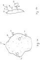
Figure 9d illustrates a synthetic bead having an irregular shape, according to the present invention. -
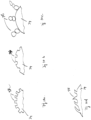
Figure 10a illustrates the surface of a synthetic bead with grooves and/or rods, according to the present invention. -
Figure 10b illustrates the surface of a synthetic bead with dents and/or holes, according to the present invention. -
Figure 10c illustrates the surface of a synthetic bead with stacked beads, according to the present invention. -
Figure 10d illustrates the surface of a synthetic bead with hair-like physical structures, according to the present invention. -
Figure 11 is a diagram of a flotation system, process or apparatus, a -
Figure 12 is a diagram of a flotation cell or column that may be used in place of the flotation cell or column that forms part of the flotation system, process or apparatus shown inFigure 11 . -
Figure 13a shows a generalized synthetic bead functionalized to be hydrophobic, wherein the bead can be a size-based bead or bubble or, weight-based polymer bead and bubble. -
Figure 13b illustrates an enlarged portion of the hydrophobic synthetic bead showing a wetted mineral particle attaching the hydrophobic surface of the synthetic bead, according to the present invention. -
Figure 13c illustrates an enlarged portion of the hydrophobic synthetic bead showing a hydrophobic non-mineral particle attaching the hydrophobic surface of the synthetic bead, (outside the scope of the present invention). -
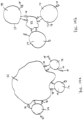
Figures 14a illustrates a mineral particle being attached to a number of much smaller synthetic beads at the same time. -
Figures 14b illustrates a mineral particle being attached to a number of slightly larger synthetic beads at the same time. -
Figures 15a illustrates a wetted mineral particle being attached to a number of much smaller hydrophobic synthetic beads at the same time. -
Figures 15b illustrates a wetted mineral particle being attached to a number of slightly larger hydrophobic synthetic beads at the same time. -
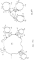
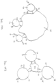
Figures 16a and 16b illustrate some embodiments of the present invention wherein the synthetic bead or bubble have one portion functionalized to have collector molecules and another portion functionalized to be hydrophobic. -
Figures 1-6 show an apparatus or material for use in, or forming part of, a separation process to be implemented in separation processor technology. The apparatus shown inFigures 1-4 features synthetic bubbles or beads having a solid-phase body made of a synthetic material, the solid-phase body comprising a surface, - a plurality of molecules attached to at least part of the surface, the molecules comprising a functional group selected for attracting one or more mineral particles to the molecules,
- wherein the synthetic material is selected from a group consisting of polyamides (nylon), polyesters, polyurethanes, phenol-formaldehyde, urea-formaldehyde, melamine-formaldehyde, polyacetal, polyethylene, polyisobutylene, polyacrylonitrile, poly(vinyl chloride), polystyrene, poly(methyl methacrylate), poly(vinyl acetate), poly(vinylidene chloride), polyisoprene, polybutadiene, polyacrylates, poly(carbonate), phenolic resin and polydimethylsiloxane,
- said functional group is configured to cause the surface to be hydrophobic,
- the surface is made of a polymer functionalized with the molecules, and
- In
Figure 1 , the synthetic bubble orbead 10 is a size-based solid polymer bead andbubble 11 functionalized to attach to thevaluable material 12 of interest in the mixture and to be separated from the mixture based on size. InFigure 2 , the synthetic bubble orbead 20 is a size-based bead andbubble 20 having a core material 21 and apolymer encapsulation 23 functionalized to attach to thevaluable material 22 of interest in the mixture and to be separated from the mixture based on size. The core material 21 may include materials such as sand, silica or other suitable material, with only synthetic material as defined inclaim 1 being within the scope of the present invention. - Polymers or polymer-based materials that may be functionalized to attach to such a valuable material, such as valuable material 12 (
Fig. 1 ), 22 (Fig. 2 ), 32 (Fig. 3 ), 42 (Fig. 4 ), 52 (Fig. 5 ), 62 (Fig. 6 ), of interest, such as copper, gold, nickel, lead or other mineral are known in the art. It should be noted that the bubbles or beads are referred herein as synthetic bubbles or beads. The term "polymer" in this disclosure means a large molecule made of many units of the same or similar structure linked together. The unit can be a monomer or an oligomer which forms the basis of, for example, the synthetic material of the solid-phase body, i.e. polyamides (nylon), polyesters, polyurethanes, phenol-formaldehyde, urea-formaldehyde, amide, melamine-formaldehyde, polyacetal, polyethylene, polyisobutylene, polyacrylonitrile, poly(vinyl chloride), polystyrene, poly(methyl methacrylates), poly(vinyl acetate), poly(vinylidene chloride), polyisoprene, polybutadiene, polyacrylates, poly(carbonate), phenolic resin and polydimethylsiloxane. Thus, the synthetic material can be hard or rigid like plastic or soft and flexible like an elastomer. While the physical properties of the synthetic beads can vary, the surface of the synthetic beads is chemically functionalized to provide one or more functional groups to attract or attach to mineral particles. The entire synthetic material may be functionalized, such that if the surface of the material is worn, abraded or otherwise consumed, new functionalized material is exposed to attract and attach to the mineral particles. (By way of example, the term "functional group" may be understood to be a group of atoms responsible for the characteristic reactions of a particular compound, including which define the structure of a family of compounds and determine its properties.) The terms "valuable material" and "mineral particle" are used herein interchangeably. - According to the present invention, the synthetic bubbles or
beads Figures 1 and 2 may be configured to be separated from the mixture based at least partly on the difference between the size of the enriched synthetic bubbles or beads having thevaluable material bead beads beads - In
Figure 3 , the synthetic bubble orbead 30 is a weight-based solid polymer bead and bubble 31 functionalized to attach to thevaluable material 32 of interest in the mixture and to be separated from the mixture based on weight. InFigure 4 , the synthetic bubbles orbeads 40 is a weight-based bead andbubble 40 having a core material 41 and apolymer encapsulation 43 functionalized to attach to thevaluable material 42 of interest in the mixture and to be separated from the mixture based on weight. The core material 41 may be air and also configured with a polymer encapsulation. - According to the present invention, the synthetic bubbles or
beads beads - In
Figure 5 , the synthetic bead or bubble 50 is shown as a magnetic-based bead and bubble (outside the scope ot he invention) having a ferro- or ferri-magnetic core 51 and apolymer encapsulation 53, such that the ferro-magnetic or ferri-magnetic core 51 attracts to paramagnetic surfaces. InFigure 6 , the synthetic bead or bubble is shown as a magnetic-based bead and bubble (outside the scope of the invention) having a para-magnetic core 61 and apolymer encapsulation 63, such that the para-magnetic core attracts to magnetized surfaces. - The synthetic bubbles or
beads 50, 60 may be configured to be separated from the mixture based at least partly on the difference between the para-, ferri-, ferro-magnetism of the enriched synthetic bubbles or beads having thevaluable material claim 1 are within the scope of this invention. - For aiding a person of ordinary skill in the art in understanding various embodiments of the present invention,
Figure 7a shows a generalized synthetic bead andFigure 7b shows an enlarged portion of the surface. The synthetic bead can be a size-based bead or bubble or weight-based polymer bead and bubble as described in conjunction withFigures 1 to 4 . As shown inFigures 7a and 7b , thesynthetic bead 70 has a bead body to provide abead surface 74. The bead body is made of a synthetic material, i.e. a particular polymer as defined inclaim 1, so as to provide a plurality of molecules ormolecular segments 76 on thesurface 74. Themolecule 76 is used to attach a chemicalfunctional group 78 to thesurface 74. In general, themolecule 76 can be a hydrocarbon chain, for example, and thefunctional group 78 can have an anionic bond (or anion) for bonding a mineral, such as copper, to thesurface 74. A xanthate, for example, has both thefunctional group 78 and themolecular segment 76 to be incorporated into the polymer that is used to make thesynthetic bead 70. Thefunctional group 78 is also known as a collector that is either ionic or non-ionic. The ion can be anionic or cationic. An anion includes oxyhydryl, such as carboxylic, sulfates and sulfonates, and sulfhydral, such as xanthates and dithiophosphates. Other molecules or compounds that can be used to provide thefunction group 78 include, but are not limited to, thionocarboamates, thioureas, xanthogens, monothiophosphates, hydroquinones and polyamines. - Similarly, a chelating agent can be incorporated into or onto the polymer as a collector site for attracting a mineral, such as copper. As shown in
Figure 7b , amineral particle 72 is attached to thefunctional group 78 on themolecule 76. In general, themineral particle 72 is much smaller than thesynthetic bead 70.Many mineral particles 72 can be attracted to or attached to thesurface 74 of asynthetic bead 70. When themineral particles 72 are very fine, smallersynthetic beads 70 can also be used. - In the present invention, a synthetic bead takes the form of a solid-phase body made of a synthetic material, i.e. a particular polymer. (By way of example, the term "solid-phase body" is understood herein to be a body having a cohesive force of matter that is strong enough to keep the molecules or atoms in the given positions, restraining the thermal mobility.) The particular polymer of the synthetic material is defined in claim 1.The polymer can be rigid or elastomeric. An elastomeric polymer can be polyisoprene, polybutadiene or natural rubber, for example. The body has a surface comprising a plurality of molecules with one or more functional groups for attracting or attaching mineral particles to the surface. A polymer having a functional group to attract or collect mineral particles is referred to as a functionalized polymer. In one embodiment, the
entire body 82 of thesynthetic bead 80 is made of the same functionalized material, as shown inFigure 8a . In another embodiment, the bead body is a shell, as shown inFigure 8b . Theshell 84 can be formed by way of expansion, such as thermal expansion or pressure reduction. - The
shell 84 can be formed as a micro-bubble or a balloon. InFigure 8b , theshell 84, which is made of functionalized material, has aninterior part 86. Theinterior part 86 can be filled with air or gas to aid buoyancy, for example. Theinterior part 86 can be used to contain a liquid to be released during the mineral separation process. The encapsulated liquid can be a polar liquid or a non-polar liquid, for example. The encapsulated liquid can contain a depressant composition for the enhanced separation of copper, nickel, zinc, lead in sulfide ores in the flotation stage, for example. In embodiments outside the scope of the invention, theshell 84 can be used to encapsulate a powder which can have a magnetic property so as to cause the synthetic bead to be magnetic, for example. The encapsulated liquid or powder may contain monomers, oligomers or short polymer segments for wetting the surface of mineral particles when released from the beads. For example, each of the monomers or oligomers may contain one functional group for attaching to a mineral particle and one charge species for attaching the wetted mineral particle to the synthetic bead. Theshell 84 can be used to encapsulate a solid core, such as Styrofoam to aid buoyancy, for example. In yet another embodiment, only the coating of the bead body can be made of functionalized polymer. The functionalized polymer is selected from polysiloxanates. As shown inFigure 8c (outside the scope of the invention), the synthetic bead can have a core 90 made of ceramic, glass or metal and only the surface of core 90 can have acoating 88 made of functionalized polymer. The core 90 can be a hollow core or a filled core depending on the applications. The core 90 can be a micro-bubble, a sphere or balloon. For example a filled core made of metal makes the density of the synthetic bead to be higher than the density of the pulp slurry, for example. The core 90 can be made of a magnetic material so that the para-, ferri-, ferro-magnetism of the synthetic bead is greater than the para-, ferri-, ferro-magnetism of the unwanted ground ore particle in the mixture. According to some embodiments, the synthetic bead can be configured with a ferro-magnetic or ferri-magnetic core that attract and attach to paramagnetic surfaces. A core 90 made of glass or ceramic can be used to make the density of the synthetic bead substantially equal to the density of the pulp slurry so that when the synthetic beads are mixed into the pulp slurry for mineral collection, the beads can be in a suspension state. - According to an embodiment of the present invention, the
synthetic bead 80 can be a porous block or take the form of a sponge or foam with multiple segregated gas filled chambers. The combination of air and thesynthetic beads 80 can be added to traditional naturally aspirated flotation cell. - It should be understood that the use of the term "bead" is not intended to limit the shape of the synthetic bead of the present invention to being spherical, as shown in
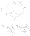
Figure 7 . In some embodiments of the present invention, thesynthetic bead 80 can have an elliptical shape as shown inFigure 9a . The synthetic bead can have a cylindrical shape as shown inFigure 9b . The synthetic bead can have a shape of a block as shown inFigure 9c . Furthermore, the synthetic bead can have an irregular shape, as shown inFigure 9d . In effect, the scope of the invention is not intended to be limited to any particular type or kind of shape of thesynthetic bead 80. - It should also be understood that the surface of a synthetic bead, according to the present invention, is not limited to an overall smooth surface as shown in
Figure 7a . In some embodiments of the present invention, the surface can be irregular and rough. For example, thesurface 74 can have somephysical structures 92 like grooves or rods as shown inFigure 10a . Thesurface 74 can have some physical structures 94 like holes or dents as shown inFigure 10b . Thesurface 74 can have some physical structures 96 formed from stacked beads as shown inFigure 10c . Thesurface 74 can have some hair-likephysical structures 98 as shown inFigure 10d . In addition to the functional groups on the synthetic beads that attract mineral particles to the bead surface, the physical structures can help trapping the mineral particles on the bead surface. Thesurface 74 can be configured to be a honeycomb surface or a sponge-like surface for trapping the mineral particles and/or increasing the contacting surface. In effect, the scope of the invention is not intended to be limited to any particular type or kind of surface of thesynthetic bead 80. - It should be noted that the synthetic beads of the present invention can be realized by a different way to achieve the same goal. Namely, it is possible to use a different means to attract the mineral particles to the surface of the synthetic beads. For example, the surface of the polymer beads or shells can be functionalized with a hydrophobic chemical molecule or compound. Alternatively, in embodiments outside the scope of the invention, the surface of beads made of glass, ceramic and metal can be coated with hydrophobic chemical molecules or compounds. Using the coating of glass beads (outside the scope of the invention) as an example, polysiloxanates can be used to functionalize the glass beads in order to make the synthetic beads. In the pulp slurry, xanthate and hydroxamate collectors can also be added therein for collecting the mineral particles and making the mineral particles hydrophobic. When the synthetic beads are used to collect the mineral particles in the pulp slurry having a pH value around 8-9, it is possible to release the mineral particles on the enriched synthetic beads from the surface of the synthetic beads in an acidic solution, such as a sulfuric acid solution. According to some embodiment, it may also be possible to release the mineral particles carried with the enriched synthetic beads by sonic agitation, such as ultrasonic waves, or simply by washing it with water.
- Flotation Apparatus wherein synthetic beads according to this invention can be used (described for illustrative purposes).
-
Figure 11 showsan apparatus 810, having a flotation cell orcolumn 812 configured to receive a mixture of fluid (e.g. water), valuable material and unwanted material, e.g., apulp slurry 814; receive synthetic bubbles or beads 70 (Fig. 7 , for example) that are constructed to be buoyant when submerged in the pulp slurry ormixture 814 and functionalized to control the chemistry of a process being performed in the flotation cell or column, including to attach to the valuable material in the pulp slurry ormixture 814; and provide enriched synthetic bubble or beads 818 having the valuable material attached thereon. By way of example, the synthetic bubbles orbeads 70 are synthetic beads according to this invention. The flotation cell orcolumn 812 is configured with a top portion or piping 820 to provide the enriched synthetic beads 818 from the flotation cell orcolumn 812 for further processing consistent with that set forth herein. - The flotation cell or
column 812 may be configured with a top part or piping 822, e.g., having avalve 822a, to receive the pulp slurry ormixture 814 and also with a bottom part or piping 824 to receive thesynthetic beads 70. In operation, the buoyancy of thesynthetic beads 70 causes them to float upwardly from the bottom to the top of the flotation cell orcolumn 812 through the pulp slurry ormixture 814 in the flotation cell orcolumn 812 so as to collide with the water, valuable material and unwanted material in the pulp slurry ormixture 814. The functionalization of thesynthetic beads 70 causes them to attach to the valuable material in the pulp slurry ormixture 814. As a result of the collision between thesynthetic beads 70 and the water, valuable material and unwanted material in the pulp slurry ormixture 814, and the attachment of thesynthetic beads 70 and the valuable material in the pulp slurry ormixture 814, the enrichedsynthetic beads 70 having the valuable material attached thereto will float to the top of theflotation cell 812 and form part of the froth formed at the top of theflotation cell 812. Theflotation cell 812 may include a top part or piping 820 configured to provide the enriched synthetic beads 818 having the valuable material attached thereto, which may be further processed consistent with that set forth herein. In effect, the enriched synthetic bubbles 818 may be taken off the top of theflotation cell 812 or may be drained off by the top part orpiping 820. - The flotation cell or
column 812 may be configured to contain an attachment rich environment, including where the attachment rich environment has a high pH, so as to encourage the flotation recovery process therein. The flotation recovery process includes the recovery of ore particles in mining, including copper. The use of the synthetic beads according to the invention is not limited to any particular type or kind of flotation recovery process. The use of synthetic beads of the invention is also not limited to any particular type or kind of mineral of interest that may form part of the flotation recovery process. - According to some embodiments of the present invention, the
synthetic beads 70 may be configured with a surface area flux by controlling some combination of the size of thesynthetic beads 70 and/or the injection rate that the pulp slurry ormixture 814 is received in the flotation cell orcolumn 812. Thesynthetic beads 70 may also be configured with a low density so as to behave like air bubbles. Thesynthetic beads 70 may also be configured with a controlled size distribution that may be customized to maximize recovery of different feed matrixes to flotation as valuable material quality changes, including as the quality of the ore changes. - The flotation cell or
column 812 may be configured to receive thesynthetic beads 70 together with air, where the air is used to create a desired froth layer in the mixture in the flotation cell orcolumn 812 in order to achieve a desired grade of valuable material. Thesynthetic beads 70 may be configured to lift the valuable material to the surface of the mixture in the flotation cell or column. - The
apparatus 810 may also include piping 826 having avalve 826a for providing tailings to a thickener 828 configured to receive the tailings from the flotation cell orcolumn 812. The thickener 828 includes piping 830 having avalve 830a to provide thickened tailings. The thickener 828 also includes suitable piping 832 for providing reclaimed water back to the flotation cell orcolumn 812 for reuse in the process. Thickeners like element 828 are known in the art, and the use of the synthetic beads of the invention is not limited to any particular type or kind. - The
apparatus 810 may further comprises a bead recovery process or processor generally indicated as 850 configured to receive the enriched synthetic beads 818 and provide reclaimed synthetic beads 852 without the valuable material attached thereon so as to enable the reuse of the psynthetic beads 852 in a closed loop process. By way of example, the bead recovery process orprocessor 850 may take the form of a washing station whereby the valuable material is mechanically, chemically, or electro-statically removed from the synthetic beads 818. - The bead recovery process or
processor 850 may include a second flotation cell orcolumn 854 havingpiping 856 with avalve 856a configured to receive the enriched synthetic beads 818; and substantially release the valuable material from the synthetic beads 818, and also having a top part or piping 857 configured to provide the reclaimed synthetic beads 852, substantially without the valuable material attached thereon. The second flotation cell orcolumn 854 may be configured to contain a release rich environment, including where the release rich environment has a low pH, or including where the release rich environment results from ultrasonic waves pulsed into the second flotation cell orcolumn 854. - The bead recovery process or
processor 850 may also include piping 858 having avalve 856a for providing concentrated minerals to athickener 860 configured to receive the concentrated minerals from the flotation cell orcolumn 854. Thethickener 860 includes piping 862 having a valve 862a to provide thickened concentrate. Thethickener 860 also includessuitable piping 864 for providing reclaimed water back to the second flotation cell orcolumn 854 for reuse in the process. Thickeners likeelement 860 are known in the art, and the use of the synthetic beads of the invention is not limited to any particular type or kind. - The enriched synthetic beads or bubbles may be also placed in a chemical solution so the valuable material is dissolved off, or may be sent to a smelter where the valuable material is burned off, including where the synthetic beads or bubbles are reused afterwards.
-
Figure 12 shows alternative apparatus generally indicated as 900 in the form of an alternative flotation cell 901 that is based at least partly on a collision technique between the mixture and the synthetic bubbles or beads. The mixture 902, e.g. the pulp slurry, may be received in a top part or piping 904, and the synthetic bubbles or beads 906 may be received in a bottom part or piping 908. The flotation cell 901 may be configured to include a first device 910 for receiving the mixture 902, and also may be configured to include asecond device 912 for receiving the polymer-based materials. The first device 910 and thesecond device 912 are configured to face towards one another so as to provide the mixture 902 and the synthetic bubbles or beads 906, using the collision technique. InFigure 12 , the arrows 910a represent the mixture being sprayed, and the arrows 912a represent the synthetic bubbles or beads 906 being sprayed towards one another in the flotation cell 901. - In operation, the collision technique causes vortices and collisions using enough energy to increase the probability of touching of the synthetic beads 906 and the valuable material in the mixture 902, but not too much energy to destroy bonds that form between the synthetic beads 906 and the valuable material in the mixture 902. Pumps, not shown, may be used to provide the mixture 902 and the synthetic bubbles or beads 906 at the appropriate pressure in order to implement the collision technique.
- By way of example, the first device 910 and the
second device 912 may take the form of shower-head like devices having a perforated nozzle with a multiplicity of holes for spraying the mixture and the synthetic bubbles or beads towards one another. Shower-head like devices are known in the art, and the use of the synthetic beads of the invention is not limited to any particular type or kind thereof. Moreover, based on that disclosed in the instant patent application, a person skilled in the art without undue experimentation would be able to determine the number and size of the holes for spraying the mixture 902 and the synthetic bubbles or beads 906 towards one another, as well as the appropriate pumping pressure in order to provide enough energy to increase the probability of touching of the synthetic beads 906 and the valuable material in the mixture 902, but not too much energy to destroy bonds that form between the synthetic beads 906 and the valuable material in the mixture 902. - As a result of the collision between the synthetic bubbles or beads 906 and the mixture, enriched synthetic bubbles or beads having the valuable material attached thereto will float to the top and form part of the froth in the flotation cell 901. The flotation cell 901 may include a top part or piping 914 configured to provide enriched synthetic bubbles or beads 916, e.g., enriched synthetic bubbles as shown, having the valuable material attached thereto, which may be further processed consistent with that set forth herein.
- The alternative apparatus 900 may be used in place of the flotation columns or cells, and inserted into the apparatus or system shown in
Figure 11 , and may prove to be more efficient than using the flotation columns or cells. - It should be understood that the sized-based bead or bubble or weight-based bead or bubble as described in conjunction with
Figures 1 to 4 can be functionalized to be hydrophobic so as to attract mineral particles.Figure 13a shows a generalized hydrophobic synthetic bead,Figure 13b shows an enlarged portion of the bead surface and a mineral particle, andFigure 13c shows an enlarged portion of the bead surface and a non-mineral particle. Attracting non-mineral particles is outside the scope of this invention. The synthetic beads have a structure and composition as defined inclaim 1 As shown inFigure 13a the hydrophobicsynthetic bead 170 has apolymer surface 174 and a plurality ofparticles 172, 172' attached to thepolymer surface 174.Figure 13b shows an enlarged portion of thepolymer surface 174 on which a plurality ofmolecules 179 render thepolymer surface 174 hydrophobic. Amineral particle 171 in the slurry, after combined with one ormore collector molecules 73, becomes a wettedmineral particle 172. Thecollector molecule 73 has afunctional group 78 attached to themineral particle 171 and a hydrophobic end ormolecular segment 76. The hydrophobic end ormolecular segment 76 is attracted to thehydrophobic molecules 179 on thepolymer surface 174.Figure 13c shows an enlarged portion of thepolymer surface 174 with a plurality ofhydrophobic molecules 179 for attracting a non-mineral particle 172'. Attracting non-mineral particles is outside the scope of this invention. The non-mineral particle 172' has a particle body 171' with one or more hydrophobicmolecular segments 76 attached thereto. The hydrophobic end ormolecular segment 76 is attracted to thehydrophobic molecules 179 on thepolymer surface 174. The term "polymer" in this specification means a large molecule made of many units of the same or similar structure linked together. Furthermore, the polymer associated withFigures 13a-13c can be naturally hydrophobic or functionalized to be hydrophobic. Some polymers having a long hydrocarbon chain or silicon-oxygen backbone, for example, tend to be hydrophobic. Hydrophobic polymers include polystyrene, poly(d,l-lactide), poly(dimethylsiloxane), polypropylene, polyacrylic, polyethylene, etc. In embodiments outside the scope of this invention,synthetic bead 170 can be made of glass to be coated with hydrophobic silicone polymer including polysiloxanates so that the bubbles or beads become hydrophobic. The bubbles or beads can be made of metal (outside the scope of the invention) to be coated with silicone alkyd copolymer, for example, so as to render the bubbles or beads hydrophobic. The bubbles or beads can be made of ceramic (outside the scope of the invention) to be coated with fluoroalkylsilane, for example, so as to render the bubbles and beads hydrophobic. According to the present invention, the bead body is made of particular hydrophobic polymers, as defined inclaim 1, to provide a hydrophobic surface. - For the purpose of describing and understanding the present invention, a physical property is understood to be any quality that is a measurable whose value describes a physical system's state. Changes in the physical properties of a system can be used to describe its transformations (or evolutions between its momentary states). Physical properties can be intensive or extensive, where an intensive property does not depend on the size or amount of matter in the object, while an extensive property does. Physical properties are contrasted with chemical properties which determine the way a material behaves in a chemical reaction. Physical properties are properties that do not change the chemical nature of matter.
- By way of example, the present invention is described in relation to physical property of the synthetic beads or bubbles that take the form of size, weight and density.
- The scope of the invention is described in relation to mineral separation, including the separation of copper or other minerals from ore.
- By way of example, applications are envisioned to include rougher, scavenger, cleaner and rougher/scavenger separation cells in the production stream, replacing, supplementing or modifying the traditional flotation machines.
- Tailings scavenger cells are used to scavenge the unrecovered minerals from a tailings stream.
- Tailings cleaning cell is used to clean unwanted material from the tailings stream before it is sent to the disposal pond.
- Tailings reclamation machine that is placed in the tailings pond or otherwise used to recover valuable mineral that has been sent to the tailings pond.
- In a typical mineral separation process, an ore is blasted into manageable pieces of mineral-containing rock. The blasted ore is then subjected to grinding where the rock is crushed into small particles in the order of 100 µm. The particles are referred herein as mineral particles but they also contain silicate minerals or oxide minerals of little or no value. These mineral particles, along with gangue minerals, are mixed with water into a pulp slurry. The synthetic beads are used to attract the mineral particles to the bead surface. The enriched synthetic beads, which are the synthetic beads having the mineral particles attached thereon, are then separated from the unwanted rock or gangue minerals by means of size-based separation or weight-based separation. For example, the separation can take place in a flotation cell, in a pipeline where the pulp slurry is transported from one location to another location, and in a mixing vat. Thereafter the mineral particles attached to the enriched synthetic beads are released from the synthetic beads for further processing, such as smelting. The releasing of the mineral particles from the synthetic beads can be carried out in different manners. For example, the enriched synthetic beads can be configured to contact a solution with a low pH value that interrupts or weakens the bonds between the mineral particles and the bead surfaces. It is also possible to submerge the enriched synthetic beads in a solution where ultrasonic waves are used to shake loose the mineral particles from the bead surface. The releasing can be carried out thermally. For example, the enriched synthetic beads can be subjected to a hot-water wash to weaken the chemical bond of the functional groups. The enriched synthetic beads can also be subjected to laser illumination where a selected laser frequency is used to weaken the chemical bond. After the releasing process, the reclaimed synthetic beads can be reused or discarded. The reclaimed synthetic beads may be recharged in order to replenish the functional groups lost during the separation and releasing processes. In order to determine whether the reclaimed synthetic beads are reusable or worth recharging, a fluorescent chemical can be incorporated onto the surface of the synthetic beads together with the functional groups. The fluorescent chemical is used as a tag for tracing such that the intensity of the fluorescence can be used as a gauge when the fluorescent chemical is excited.
- The synthetic beads, according to some embodiments of the present invention, can also be used in a dry separation process where the crushed particles are configured to contact with the synthetic beads by dry mixing. Alternatively, the synthetic beads can be contained in a filter and the crushed particles are forced by forced air to pass through the filter. Again, the mineral particles attached on the enriched synthetic beads can be released in a low pH environment, in a ultrasonic agitation environment, in a hot water bath or in a laser illuminated area.
- The synthetic beads, according to some embodiments of the present invention, can be made with different sizes in order to attract mineral particles of different sizes. For example, unlike air bubbles, the synthetic beads of a larger size can be used to attract mineral particles larger than, say, 200µm. Thus, the grinding of the blasted ore can be separated into different stages. In the first stage, the rock is crushed into particles in the order of 200 µm. After the separation process using the larger synthetic beads in the slurry containing these crude particles, the remaining slurry can be subjected to a finer grinding stage where the crushed rock is further crushed into particles in the order of 100µm. With the slurry containing the finer mineral particles, synthetic beads with a smaller size may be more effective in interacting with the finer mineral particles. In a flotation cell application, the bead size can be smaller than 100µm. In a tailings pond application, the bead size can be 1mm to 10mm or larger. However, large beads would reduce the functionalized surfaces where the mineral particles can attach to the synthetic beads. Thus, according to some embodiments of the present invention, the synthetic beads are configured with a size less than 100 µm for attracting to mineral particles having a substantially similar size, including in applications related to flotation cells; the synthetic beads are configured with a size of about 100 µm for attracting or attaching to mineral particles having a substantially similar size, smaller size or larger size; the synthetic beads are configured with a size in a range of about 50-500 µm for attracting or attaching to mineral particles having a substantially similar size, smaller size or larger size; the synthetic beads are configured with a size about 200 µm for attracting to mineral particles having a substantially similar size; the synthetic beads are configured with a size in a range of about 1mm to 10mm, including in applications related to a tailings pond. In general, the synthetic beads are configured with a size in a range of about 50 µm to 1 0mm. But the beads can be smaller than 50 µm and larger than 10mm.
-
Figure 14a illustrates a scenario where amineral particle 72 is attached to a number ofsynthetic beads 74 at the same time. Thus, although thesynthetic beads 74 are much smaller in size than themineral particle 72, a number ofsynthetic beads 74 may be able to lift themineral particle 72 upward in a flotation cell. Likewise, asmaller mineral particle 72 can also be lifted upward by a number ofsynthetic beads 74 as shown inFigure 14b . In order to increase the likelihood for this "cooperative" lifting to occur, a large number ofsynthetic beads 74 can be mixed into the slurry. Unlike air bubbles, the density of the synthetic beads can be chosen such that the synthetic beads may stay along in the slurry before they rise to surface in a flotation cell. -
Figures 15a and 15b illustrate a similar scenario. As shown, a wettedmineral particle 172 is attached to a number of hydrophobicsynthetic beads 174 at the same time. - According to some embodiments of the present invention, the
synthetic beads Figures 7a and13a . As such, a plurality ofmineral particles synthetic bead synthetic beads mineral particles Figures 14a and15a As such, a plurality ofsynthetic beads mineral particle synthetic beads mineral particle Figures 14b and15b . According to some embodiments of the present invention, only a portion of the surface of thesynthetic bead 174 is functionalized to be hydrophobic (with molecules 179). This has the benefits as follows: - 1. Keeps too many beads from clumping together - or limits the clumping of beads,
- 2. Once a mineral is attached, the weight of the mineral is likely to force the bead to rotate, allowing the mineral particle to be located under the bead as it rises through the flotation cell;
- a. Better cleaning as it may let the gangue to pass through,
- b. Protects the attached mineral particle or particles from being knocked off, and
- c. Provides clearer rise to the top collection zone in the flotation cell.
- According to some embodiments of the present invention, only a portion of the surface of the
synthetic bead 74 is functionalized to have a functional group being acollector 78. Thecollector 78 has an ion for bonding to a mineral particle. This has the benefits as follows:
Once a mineral is attached, the weight of the mineral is likely to force the bead to rotate, allowing the mineral particle to be located under the bead as it rises through the flotation cell; - a. Better cleaning as it may let the gangue to pass through
- b. Protects the attached mineral particle or particles from being knocked off, and
- c. Provides clearer rise to the top collection zone in the flotation cell.
- According to some embodiments of the present invention, one part of the synthetic bead is functionalized with collectors while another part of same synthetic bead is functionalized to be hydrophobic as shown in
Figures 16a and 16b . As shown inFigure 16a , asynthetic bead 74 has a surface portion where polymer is functionalized to havecollector molecules 73 withfunctional group 78 andmolecular segment 76 attached to the surface of thebead 74. Thesynthetic bead 74 also has a different surface portion where polymer is functionalized to havehydrophobic molecules 179. In the embodiment as shown inFigure 16b , the entire surface of thesynthetic bead 74 can be functionalized to havecollector molecules 73, but a portion of the surface is functionalized to havehydrophobic molecules 179 render it hydrophobic. - According to some embodiments of the present invention, one part of the synthetic bead is functionalized with collectors while another part of same synthetic bead is functionalized to be hydrophobic and this "hybrid" synthetic bead is configured for use in a traditional flotation cell as well. The "hybrid" synthetic bead (see
Figures 16a and 16b ) has a hydrophobic portion and a separate collector portion. When the "hybrid" beads are mixed with air in the flotation cell, some of them will attach to the air bubbles because of the hydrophobic portion. As the "hybrid" synthetic bead is attached to an air bubble, the collector portion of the attached bead can collect mineral particles with the functional groups. Thus, the synthetic beads, according to some embodiments of the present inventions, can be used to replace the air bubbles, or to work together with the air bubbles in a flotation process. - This "hybrid" synthetic bead can collect mineral particles that are wet and not wet.
- It should be noted that, the synthetic beads, according to some embodiments of the present invention, can be used in tailings scavenger cells to scavenge the unrecovered minerals from a tailings stream. The synthetic beads can also be used in a disposal pond or the tailing ponds.
- In embodiments outside the scope of this invention, the synthetic beads, whether functionalized to have a collector or functionalized to be hydrophobic, are also configured for use in oilsands separation - to separate bitumen from sand and water in the recovery of bitumen in an oilsands mining operation.
- As described in the specification, ore mining is typically associated with copper and nickel. However, the synthetic beads are suitable for other types or kinds of valuable material or minerals of interest, including gold, molybdenum, etc.
- It should be further appreciated that any of the features, characteristics, alternatives or modifications described regarding a particular embodiment herein may also be applied, used, or incorporated with any other embodiment described herein. Although the invention has been described and illustrated with respect to exemplary embodiments thereof, the foregoing and various other additions and omissions may be made therein and thereto without departing from the scope of the present invention as defined by the appended claims.
Claims (11)
- A synthetic bead comprising:a solid-phase body made of a synthetic material, the solid-phase body comprising a surface,a plurality of molecules attached to at least part of the surface, the molecules comprising a functional group selected for attracting one or more mineral particles to the molecules,wherein the synthetic material is selected from a group consisting of polyamides (nylon), polyesters, polyurethanes, phenol-formaldehyde, urea-formaldehyde, melamine-formaldehyde, polyacetal, polyethylene, polyisobutylene, polyacrylonitrile, poly(vinyl chloride), polystyrene, poly(methyl methacrylate), poly(vinyl acetate), poly(vinylidene chloride), polyisoprene, polybutadiene, polyacrylates, poly(carbonate), phenolic resin and polydimethylsiloxane,said functional group is configured to cause the surface to be hydrophobic, the surface is made of a polymer functionalized with the molecules, andwherein the polymer is selected from the group consisting of polysiloxanates.
- The synthetic bead according to claim 1, wherein the solid-phase body comprises a shell providing the surface, the shell made of the synthetic material comprising the molecules, includingwhere the synthetic bead is configured to attract the mineral particles in an aqueous mixture, and the shell comprises an interior part arranged to encapsulate a gaseous element such that the bead has a density smaller than the aqueous mixture; and either where the mineral particles have a minimum size and the solid-phase body has a body size smaller than the minimum size, or where the mineral particles have a maximum size and the solid-phase body has a body size greater than the maximum size; orwhere the synthetic bead is configured to attract the mineral particles in an aqueous mixture, and wherein the shell comprises an interior part arranged to encapsulate a liquid having a chemical property different than the aqueous mixture, orwhere the synthetic bead is configured to attract the mineral particles in an aqueous mixture, and wherein the shell comprises an interior part arranged to encapsulate a solid-phase material different from the synthetic material, and the solid-phase material is selected to control the density of the synthetic bead relative to the density of the aqueous mixture, orwhere the shell comprises an interior part configured to encapsulate a solid-phase material different from the synthetic material.
- The synthetic bead according to claim 1, wherein the surface comprises physical structures configured to trap the mineral particles, including where the physical structures comprise grooves or dents, or where the physical structures comprise hair-like structures.
- The synthetic bead according to claim 1, whereinthe functional group has an anion for attracting the mineral particles to the surface, including where the anion comprises an oxyhydryl, including carboxylic, sulfates and sulfonates, and sulfhydral bond; orthe functional group is a collector that is either ionic or non-ionic, including that where the functional group is ionic, it is anionic or cationic.
- The synthetic bead according to claim 1, wherein the synthetic beads are configured with a size having a dimension that includes one of the following:less than 100 µm for attracting to mineral particles, including in applications related to flotation cells; or100 µm for attaching to mineral particles; ora range of 50-500 µm for attracting to mineral particles; or200 µm for attracting to mineral particles; ora range of 1 mm to 10 mm, including in applications related to a tailings pond; ora range of 50 µm to 10 mm.
- The synthetic bead according to claim 1,wherein only said at least part of the surface is configured to have the molecules attached thereto, wherein the molecules comprise collectors, including where another part of the surface is configured to be hydrophobic; orwherein a part of the surface is configured to be hydrophobic.
- A method for producing a synthetic bead or bubble, comprising:providing a solid-phase body made of a synthetic material, the solid-phase body comprising a surface,attaching a plurality of molecules to the surface, the molecules comprising a functional group selected for attracting one or more mineral particles to the molecules, wherein the synthetic material is selected from a group consisting of polyamides (nylon), polyesters, polyurethanes, phenol-formaldehyde, urea-formaldehyde, melamine-formaldehyde, polyacetal, polyethylene, polyisobutylene, polyacrylonitrile, poly(vinyl chloride), polystyrene, poly(methyl methacrylate), poly(vinyl acetate), poly(vinylidene chloride), polyisoprene, polybutadiene, polyacrylates, poly(carbonate), phenolic resin and polydimethylsiloxane,said functional group is configured to cause the surface to be hydrophobic, the surface is made of a polymer functionalized with the molecules, andwherein the polymer is selected from the group consisting of polysiloxanates.
- The method according to claim 7, wherein the solid-phase body comprises a shell providing the surface, the shell made of the synthetic material, wherein said attaching comprises bonding the molecules to the synthetic material, includingwhere the synthetic bead is configured to attract the mineral particles in an aqueous mixture, and wherein the shell comprises an interior part, said method further comprising: encapsulating a gaseous element in the interior part such that the synthetic bead has a density less than the aqueous mixture, or includingwhere the synthetic bead is configured to attract the mineral particles in an aqueous mixture, and wherein the shell comprises an interior part, said method further comprising: encapsulating a solid-phase material in the interior part, the solid-phase material being different from the synthetic material, and the solid-phase material is selected to control the density of the synthetic bead relative to the density of the aqueous mixture.
- The method according to claim 7, wherein the functional group has an anion for attracting the mineral particles to the surface.
- The method according to claim 7, wherein the functional group is a collector configured to be either ionic or non-ionic, including that where the functional group comprises an ion, it is an anion or a cation.
- The method according to claim 7, wherein the functional group is a collector configured to be either ionic or non-ionic, and where the functional group is ionic, it comprises an anion being an oxyhydryl, including carboxylic, sulfates and sulfonates, and sulfhydral bond.
Applications Claiming Priority (3)
| Application Number | Priority Date | Filing Date | Title |
|---|---|---|---|
| US201161489893P | 2011-05-25 | 2011-05-25 | |
| US201161533544P | 2011-09-12 | 2011-09-12 | |
| PCT/US2012/039576 WO2012162609A1 (en) | 2011-05-25 | 2012-05-25 | Synthetic beads/bubbles functionalized with molecules for attracting and attaching to mineral particles of interest |
Publications (4)
| Publication Number | Publication Date |
|---|---|
| EP2714792A1 EP2714792A1 (en) | 2014-04-09 |
| EP2714792A4 EP2714792A4 (en) | 2015-04-22 |
| EP2714792C0 EP2714792C0 (en) | 2024-07-03 |
| EP2714792B1 true EP2714792B1 (en) | 2024-07-03 |
Family
ID=47217769
Family Applications (9)
| Application Number | Title | Priority Date | Filing Date |
|---|---|---|---|
| EP12788746.1A Active EP2717988B1 (en) | 2011-05-25 | 2012-05-25 | Synthetic beads having hydrophobic surface |
| EP12789209.9A Active EP2715055B1 (en) | 2011-05-25 | 2012-05-25 | Mineral separation using sized-, weight-or magnetic-based polymer bubbles or beads |
| EP12789071.3A Active EP2714792B1 (en) | 2011-05-25 | 2012-05-25 | Synthetic beads functionalized with molecules for attracting and attaching to mineral particles of interest |
| EP12788889.9A Active EP2714596B1 (en) | 2011-05-25 | 2012-05-25 | Method and apparatus for releasing mineral from synthetic beads |
| EP12849063.8A Active EP2714949B1 (en) | 2011-05-25 | 2012-05-25 | Mineral recovery in tailings using hydroxyl-terminated polydimethylsiloxanes |
| EP12789960.7A Active EP2714248B1 (en) | 2011-05-25 | 2012-05-25 | Mineral separation |
| EP12792251.6A Active EP2714242B1 (en) | 2011-05-25 | 2012-05-25 | Flotation separation using beads or bubbles containing polydimethylsiloxane |
| EP12790002.5A Active EP2714235B1 (en) | 2011-05-25 | 2012-05-25 | Mineral separation using functionalized polymer coated member |
| EP12849247.7A Active EP2714233B1 (en) | 2011-05-25 | 2012-05-25 | Synthetic beads in a flotation cell or column |
Family Applications Before (2)
| Application Number | Title | Priority Date | Filing Date |
|---|---|---|---|
| EP12788746.1A Active EP2717988B1 (en) | 2011-05-25 | 2012-05-25 | Synthetic beads having hydrophobic surface |
| EP12789209.9A Active EP2715055B1 (en) | 2011-05-25 | 2012-05-25 | Mineral separation using sized-, weight-or magnetic-based polymer bubbles or beads |
Family Applications After (6)
| Application Number | Title | Priority Date | Filing Date |
|---|---|---|---|
| EP12788889.9A Active EP2714596B1 (en) | 2011-05-25 | 2012-05-25 | Method and apparatus for releasing mineral from synthetic beads |
| EP12849063.8A Active EP2714949B1 (en) | 2011-05-25 | 2012-05-25 | Mineral recovery in tailings using hydroxyl-terminated polydimethylsiloxanes |
| EP12789960.7A Active EP2714248B1 (en) | 2011-05-25 | 2012-05-25 | Mineral separation |
| EP12792251.6A Active EP2714242B1 (en) | 2011-05-25 | 2012-05-25 | Flotation separation using beads or bubbles containing polydimethylsiloxane |
| EP12790002.5A Active EP2714235B1 (en) | 2011-05-25 | 2012-05-25 | Mineral separation using functionalized polymer coated member |
| EP12849247.7A Active EP2714233B1 (en) | 2011-05-25 | 2012-05-25 | Synthetic beads in a flotation cell or column |
Country Status (14)
| Country | Link |
|---|---|
| US (11) | US9943860B2 (en) |
| EP (9) | EP2717988B1 (en) |
| CN (4) | CN104010708B (en) |
| AU (9) | AU2012337376B2 (en) |
| CA (9) | CA2836803C (en) |
| CL (9) | CL2013003378A1 (en) |
| DK (2) | DK2717988T3 (en) |
| ES (3) | ES2936663T3 (en) |
| PE (9) | PE20140708A1 (en) |
| PL (3) | PL2717988T3 (en) |
| RS (1) | RS63788B1 (en) |
| RU (3) | RU2600764C2 (en) |
| WO (9) | WO2012166580A1 (en) |
| ZA (9) | ZA201309599B (en) |
Families Citing this family (63)
| Publication number | Priority date | Publication date | Assignee | Title |
|---|---|---|---|---|
| US12186690B2 (en) | 2011-05-25 | 2025-01-07 | Cidra Corporate Services Inc. | Polymer coating for selective separation of hydrophobic particles in aqueous slurry |
| US9731221B2 (en) * | 2011-05-25 | 2017-08-15 | Cidra Corporate Services, Inc. | Apparatus having polymer surfaces having a siloxane functional group |
| US10835905B2 (en) | 2011-05-25 | 2020-11-17 | Cidra Corporate Services Inc. | Recovery media for mineral processing |
| AU2012337376B2 (en) * | 2011-05-25 | 2016-12-08 | Cidra Corporate Services Inc. | Mineral recovery in tailings using functionalized polymers |
| EP2790817B1 (en) * | 2011-12-13 | 2020-05-27 | CiDRA Corporate Services, Inc. | Mineral separation using functionalized polymer or polymer-coated filters and membranes |
| US12618010B2 (en) | 2012-02-28 | 2026-05-05 | Cidra Corporate Services Llc | Method and system for flotation separation in a magnetically controllable and steerable medium |
| US9932525B2 (en) | 2012-02-28 | 2018-04-03 | Cidra Corporate Services, Inc. | Method and system for flotation separation in a magnetically controllable and steerable medium |
| US10751693B2 (en) | 2012-05-22 | 2020-08-25 | CiDRA Corporate Service Inc. | Mineral recovery using hydrophobic polymer surfaces |
| WO2014110121A1 (en) | 2013-01-08 | 2014-07-17 | Cidra Corporate Services Inc. | Smart proppant technology for fracking and well production performance monitoring |
| US10060570B2 (en) | 2013-01-09 | 2018-08-28 | Cidra Corporate Services, Inc. | Smart pipe concept based on embedded taggant-sensor and/or color-encoded elements to monitor liner wear in lined pipelines, including urethane lined pipe |
| PE20151816A1 (en) * | 2013-05-13 | 2016-01-06 | Cidra Corporate Services Inc | POLYMERIC SURFACES THAT HAVE A FUNCTIONAL SILOXANE GROUP |
| WO2015095054A2 (en) * | 2013-12-17 | 2015-06-25 | Flsmidth A/S | Process for flotation leaching copper sulfide minerals |
| DE102014200415A1 (en) | 2013-12-20 | 2015-06-25 | Siemens Aktiengesellschaft | Process for the separation of a defined mineral substance phase from a ground ore |
| US10772997B2 (en) * | 2014-05-15 | 2020-09-15 | Ronald D. Shippert | Tissue parcelization method and apparatus |
| ES2754600T3 (en) * | 2014-05-30 | 2020-04-20 | Cidra Corporate Services Inc | Mineral recovery through the use of hydrophobic polymeric surfaces |
| US10481696B2 (en) | 2015-03-03 | 2019-11-19 | Nvidia Corporation | Radar based user interface |
| CN104815760B (en) * | 2015-03-24 | 2017-08-29 | 湖南有色金属研究院 | A kind of collecting agent for the Oxide Copper Ore Flotation technique containing magnetic impurity |
| CN104888959B (en) * | 2015-04-30 | 2017-06-23 | 中国地质科学院矿产综合利用研究所 | Quality-improving impurity-reducing beneficiation method for ferromagnetic minerals |
| CN108431304B (en) * | 2015-10-16 | 2021-04-27 | 锡德拉企业服务公司 | Opportunities for recycling enhancement processes for molybdenum production |
| WO2017066752A1 (en) * | 2015-10-16 | 2017-04-20 | Cidra Corporate Services Inc. | Mineral beneficiation utilizing engineered materials for mineral separation and coarse particle recovery |
| AU2016357752B2 (en) | 2015-11-16 | 2020-10-29 | Cidra Corporate Services Llc | Utilizing engineered media for recovery of minerals in tailings stream at the end of a flotation separation process |
| EP3181230A1 (en) * | 2015-12-17 | 2017-06-21 | Basf Se | Ultraflotation with magnetically responsive carrier particles |
| US10807105B2 (en) * | 2015-12-28 | 2020-10-20 | CiDRA CORPORATION SERVICES LLC | Tumbler cell for mineral recovery using engineered media |
| CN120535056A (en) * | 2016-01-07 | 2025-08-26 | 锡德拉企业服务有限责任公司 | Functionalized open network structures of open-cell or reticulated foams for selective separation of mineral particles in aqueous systems |
| US10416049B2 (en) * | 2016-04-05 | 2019-09-17 | The Government Of The United States Of America, As Represented By The Secretary Of The Navy | Processing of solid micron sized particles for rapid deposition on substrate surfaces with uniform particle distribution |
| PE20190703A1 (en) * | 2016-10-04 | 2019-05-15 | Cidra Corporate Services Llc | MODIFICATION TECHNIQUE FOR THE DISTRIBUTION OF THE SIZE OF PARTICLE CLASSIFICATION BASED ON HYDROPHOBIC MEDIA TO IMPROVE FLOAT SEPARATION BY FLUIDIZED MILK |
| CA3039207C (en) * | 2016-10-04 | 2022-08-02 | Cidra Corporate Services Llc | Separation of copper and molybdenum sulfides from pyrite using a sea water / desalinated water hybrid process |
| WO2018067649A1 (en) | 2016-10-04 | 2018-04-12 | Cidra Corporate Services Inc. | Hybrid - flotation recovery of mineral bearing ores |
| WO2018068049A1 (en) * | 2016-10-07 | 2018-04-12 | Cidra Corporate Services, Inc. | Non-flotation based recovery of mineral bearing ore using hydrophobic particle collection in a pipeline section |
| EP3535428B1 (en) * | 2016-11-01 | 2024-03-06 | Cidra Corporate Services LLC | Reactor system for separation and enrichment of minerals from a slurry containing minerals and other materials |
| AU2017354147A1 (en) | 2016-11-02 | 2019-05-23 | Cidra Corporate Services Llc | Polymer coating for selective separation of hydrophobic particles in aqueous slurry |
| CL2016003331A1 (en) * | 2016-12-26 | 2017-05-05 | Univ Chile | Magneto-centrifugal flotation cell for mineral concentration that reduces water consumption |
| EP3589416A4 (en) * | 2017-02-28 | 2021-01-13 | Cidra Corporate Services LLC | High intensity conditioning prior to enhanced mineral separation process |
| AU2018227463B2 (en) * | 2017-02-28 | 2022-08-25 | Cidra Corporate Services Llc. | Process configurations to prevent excess re-grinding of scavengering concentrates |
| US12048946B2 (en) | 2017-02-28 | 2024-07-30 | Cidra Corporate Services Llc | Processes for coating reticulated foams |
| EP3589764A4 (en) * | 2017-03-01 | 2021-01-13 | Cidra Corporate Services LLC | Cyclone underflow scavengering process using enhanced mineral separation circuits (emsc) |
| MX2019010384A (en) * | 2017-03-01 | 2020-01-21 | Cidra Corporate Services Llc | Polymer coating for selective separation of hydrophobic particles in aqueous slurry. |
| EP3589399B1 (en) * | 2017-03-01 | 2023-09-13 | Cidra Corporate Services LLC | Mineral processing plant |
| WO2018183244A1 (en) | 2017-03-27 | 2018-10-04 | Cidra Corporate Services Llc | Removal of hydrophobic particles using carbon dioxide |
| DE102017111515A1 (en) | 2017-05-26 | 2018-11-29 | Gebrüder Dorfner GmbH & Co. Kaolin- und Kristallquarzsand-Werke KG | Composite particles with hydrophilic and hydrophobic surface coatings |
| CN107561146A (en) * | 2017-08-15 | 2018-01-09 | 江西理工大学 | A kind of electrochemical research method closer to true mineral floating |
| KR102578304B1 (en) * | 2017-11-16 | 2023-09-13 | 시냅틱스 인코포레이티드 | Multiple gamma control technologies for display panels |
| WO2019157147A2 (en) | 2018-02-07 | 2019-08-15 | Cidra Corporate Services Llc | Open cell or reticulated foam having 3-dimensional open-network structure made of a hydrophobic material for selective separation of mineral particles |
| CN116251658A (en) * | 2018-04-04 | 2023-06-13 | 乔迪·G·罗宾斯 | Separation of minerals by specific gravity |
| JP6642616B2 (en) * | 2018-04-23 | 2020-02-05 | 栗田工業株式会社 | Treatment method for circulating water in wet painting booth |
| JP7102267B2 (en) * | 2018-07-10 | 2022-07-19 | リンテック株式会社 | Release film for ceramic green sheet manufacturing process |
| CN109046743B (en) * | 2018-07-20 | 2020-06-16 | 太原理工大学 | A composite force field separator for magnetite separation and its separation method |
| CN109127110A (en) * | 2018-08-10 | 2019-01-04 | 江苏凯达石英股份有限公司 | Pyrite-type quartz sand flotation purifying technique |
| US12059688B2 (en) | 2018-08-31 | 2024-08-13 | Gt Of Ohio, Ltd. | Method and apparatus for continuous magnetic filtration of ferrous mill scale from liquid solutions |
| CN109110967B (en) * | 2018-09-11 | 2021-09-10 | 博天环境集团股份有限公司 | Bauxite beneficiation wastewater recycling system and method based on membrane chemical reactor |
| CN109225657B (en) * | 2018-09-25 | 2020-10-20 | 北矿机电科技有限责任公司 | High concentration flotation device integrated equipment |
| CN109482333B (en) * | 2018-11-22 | 2020-02-14 | 中国矿业大学 | Dry-wet combined enrichment process for copper ore |
| CN109731696B (en) * | 2019-03-14 | 2019-12-13 | 中国矿业大学 | static flotation method suitable for coarse particle recovery |
| CN109772591A (en) * | 2019-03-22 | 2019-05-21 | 山东超美清洁能源有限公司 | A kind of energy conservation and environmental protection, helping for clean and effective select agent |
| KR102484008B1 (en) * | 2021-02-23 | 2023-01-03 | 한국원자력연구원 | Method for separating fine soil particles with pollutant adsorbed by floating process, and hydrophobic inorganic nanoparticle used therefor |
| US20230149945A1 (en) * | 2021-11-17 | 2023-05-18 | Royal Biotech Inc | Method and System for Facilitating Green Screening, Classification, and Adsorption of Target Elements from a Mixture |
| EP4590872A2 (en) | 2022-09-22 | 2025-07-30 | Cidra Corporate Services LLC | Novel promoters for mineral collection |
| WO2024112811A2 (en) | 2022-11-23 | 2024-05-30 | Good Earth Ip Holdings, Llc | Separation of minerals by gas injection |
| PE20252563A1 (en) | 2023-02-28 | 2025-10-28 | Cidra Corporate Services Llc | METHOD FOR RECOVERING AND ENHANCING LOW-CONCENTRATION SURFACTANTS FROM WASH WATER |
| CN116272436A (en) * | 2023-04-11 | 2023-06-23 | 东北大学秦皇岛分校 | A kind of iron tailings-based electrospun fiber membrane and its preparation method and application |
| CL2023003860A1 (en) * | 2023-12-21 | 2024-03-22 | Univ Concepcion | Reactor to improve the recovery of valuable elements by flotation and operation process |
| WO2025195934A1 (en) * | 2024-03-18 | 2025-09-25 | Magnify Biotechnologies Gmbh | Utilizing magnetic separation process technology to capture target compounds |
| US20250339794A1 (en) | 2024-05-06 | 2025-11-06 | Active Minerals International, Llc | Product for mine tailings |
Citations (2)
| Publication number | Priority date | Publication date | Assignee | Title |
|---|---|---|---|---|
| WO2009030669A2 (en) * | 2007-09-03 | 2009-03-12 | Basf Se | Processing rich ores using magnetic particles |
| WO2012028701A2 (en) * | 2010-09-03 | 2012-03-08 | Basf Se | Hydrophobic, functionalized particles |
Family Cites Families (147)
| Publication number | Priority date | Publication date | Assignee | Title |
|---|---|---|---|---|
| US2588976A (en) | 1952-03-11 | Filter | ||
| US1684536A (en) | 1927-01-24 | 1928-09-18 | Guggenheim Brothers | Flotation process |
| US2585473A (en) | 1947-05-03 | 1952-02-12 | Vera Alward Kennedy | Extraction apparatus and method |
| US2678132A (en) * | 1950-03-31 | 1954-05-11 | Socony Vacuum Oil Co Inc | Endless belt adsorption |
| US2699872A (en) | 1952-07-10 | 1955-01-18 | William H Kelsey | Pulp-circulating vacuum filter |
| US2934208A (en) | 1958-02-27 | 1960-04-26 | Saskatchewan Potash | Silicone reagent flotation |
| US2957576A (en) * | 1958-03-07 | 1960-10-25 | Anaconda Co | Recovery of molybdenite by flotation |
| SU118472A1 (en) * | 1958-05-12 | 1958-11-30 | Р.Н. Беловод | The method of obtaining pyrite concentrates from the tailings of copper and zinc flotation |
| US3224582A (en) | 1965-06-01 | 1965-12-21 | Huber Corp J M | Kaolin clay beneficiation |
| GB1352515A (en) | 1970-04-15 | 1974-05-08 | English Clays Lovering Pochin | Separation of particulate materials |
| US4100242A (en) | 1971-02-24 | 1978-07-11 | Leach Irby H | Method of molding aqueous settable slurries containing shredded open-cell polystyrene particles |
| IT947165B (en) * | 1971-05-17 | 1973-05-21 | Grefco | COMPOSITIONS AND PROCESS FOR THE SELECTIVE ELIMINATION OF OILY PRODUCTS FROM THE WATER |
| SU441314A1 (en) | 1971-05-20 | 1974-08-30 | Предприятие П/Я М-5885 | Method for extracting copper from acid copper-containing solutions and slurries by sorption |
| GB1339337A (en) * | 1971-11-30 | 1973-12-05 | Engelhard Min & Chem | Method for treating floated solids |
| US3796308A (en) | 1972-07-24 | 1974-03-12 | Canadian Patents Dev | Bacterial oxidation in upgrading sulfidic ores and coals |
| US3970518A (en) * | 1975-07-01 | 1976-07-20 | General Electric Company | Magnetic separation of biological particles |
| CA1085760A (en) | 1976-02-10 | 1980-09-16 | Research Council Of Alberta (The) | Process for recovering bitumen from tar sand |
| US4279756A (en) | 1976-05-03 | 1981-07-21 | Commonwealth Scientific And Industrial Research Organization | Water clarification |
| GB1582956A (en) | 1976-07-30 | 1981-01-21 | Ici Ltd | Composite magnetic particles |
| USRE30360E (en) | 1977-12-14 | 1980-08-05 | Maryland Patent Development Co., Inc. | Magnetic separation of particulate mixtures |
| US4685963A (en) | 1978-05-22 | 1987-08-11 | Texasgulf Minerals And Metals, Inc. | Process for the extraction of platinum group metals |
| US4235562A (en) | 1978-12-08 | 1980-11-25 | Ribas Alberto L | Land reclamation system |
| US4224138A (en) | 1979-05-10 | 1980-09-23 | Jan Kruyer | Process for recovering bitumen from oil sand |
| US4269699A (en) | 1979-10-23 | 1981-05-26 | Canadian Patents & Dev. Ltd. | Bioadsorption alteration of iron sulfide surfaces |
| US4304573A (en) | 1980-01-22 | 1981-12-08 | Gulf & Western Industries, Inc. | Process of beneficiating coal and product |
| US4391608A (en) | 1980-03-31 | 1983-07-05 | Dondelewski Michael A | Process for the beneficiation of carbonous materials with the aid of ultrasound |
| DE3020211A1 (en) * | 1980-05-28 | 1981-12-03 | Krauss-Maffei AG, 8000 München | METHOD FOR THE DRAINAGE OF COLORS CONTAINED IN SUSPENSIONS |
| US4313832A (en) | 1980-06-12 | 1982-02-02 | Rohm And Haas Company | Method for treatment of aqueous solutions with ion exchange fibers |
| DE3030956A1 (en) * | 1980-08-16 | 1982-03-25 | Chemische Fabrik Pfersee Gmbh, 8900 Augsburg | Oil slick absorber of peat made hydrophobic - by treating with cationic dispersion and/or pref. organo:polysiloxane(s) |
| SU1309904A3 (en) | 1981-05-13 | 1987-05-07 | Берол Кеми Аб (Фирма) | Method of foam flotation of apatite-carbonate ore |
| EP0091923B1 (en) | 1981-10-26 | 1987-03-04 | W.S.R. Pty. Ltd. | Magnetic flotation |
| US4523991A (en) * | 1982-12-27 | 1985-06-18 | The Dow Chemical Company | Carrier particle for the froth flotation of fine ores |
| US4537599A (en) | 1983-04-28 | 1985-08-27 | Greenwald Sr Edward H | Process for removing sulfur and ash from coal |
| GB8314138D0 (en) | 1983-05-21 | 1983-06-29 | British Petroleum Co Plc | Benefication of carbonaceous fuels |
| US4511461A (en) | 1983-07-06 | 1985-04-16 | Jan Kruyer | Process for recovering minerals and metals by oleophilic adhesion |
| US4526680A (en) * | 1984-05-30 | 1985-07-02 | Dow Corning Corporation | Silicone glycol collectors in the beneficiation of fine coal by froth flotation |
| US4532032A (en) | 1984-05-30 | 1985-07-30 | Dow Corning Corporation | Polyorganosiloxane collectors in the beneficiation of fine coal by froth flotation |
| US4556482A (en) | 1984-08-17 | 1985-12-03 | American Cyanamid Company | Process for the flotation of base metal sulfide minerals in acid, neutral or mildly alkaline circuits |
| GB8726857D0 (en) | 1987-11-17 | 1987-12-23 | Fospur Ltd | Froth floatation of mineral fines |
| US4981582A (en) | 1988-01-27 | 1991-01-01 | Virginia Tech Intellectual Properties, Inc. | Process and apparatus for separating fine particles by microbubble flotation together with a process and apparatus for generation of microbubbles |
| US5167798A (en) * | 1988-01-27 | 1992-12-01 | Virginia Tech Intellectual Properties, Inc. | Apparatus and process for the separation of hydrophobic and hydrophilic particles using microbubble column flotation together with a process and apparatus for generation of microbubbles |
| SU1558473A2 (en) * | 1988-03-21 | 1990-04-23 | Донецкий политехнический институт | Method of dressing and dehydration of coal |
| US4888106A (en) | 1988-04-18 | 1989-12-19 | American Cyanamid Company | Method of using polymeric sulfide mineral depressants |
| FI79953C (en) | 1988-04-28 | 1990-04-10 | Svi Distec Oy | Apparatus for flotation enrichment |
| DE3821465A1 (en) | 1988-06-25 | 1989-12-28 | Degussa | METHOD FOR THE PRODUCTION OF SINGLE OR MULTIPLE SUBSTITUTED ORGANYLOXYSILYL-FUNCTIONAL THIOUROSES AND THESE COMPOUNDS |
| US4971685A (en) | 1989-04-11 | 1990-11-20 | The United States Of America As Represented By The Secretary Of The Interior | Bubble injected hydrocyclone flotation cell |
| US5161694A (en) | 1990-04-24 | 1992-11-10 | Virginia Tech Intellectual Properties, Inc. | Method for separating fine particles by selective hydrophobic coagulation |
| AU653772B2 (en) * | 1990-12-17 | 1994-10-13 | Dow Chemical Company, The | Aryl monosulfonate collectors useful in the flotation of minerals |
| RU2022656C1 (en) * | 1990-12-29 | 1994-11-15 | Акционерное общество "Союзцветметавтоматика" (научно-производственный комплекс "Югцветметавтоматика") | Device for measuring discharge of floatation reagents in ore pulp |
| RU2038155C1 (en) * | 1991-07-04 | 1995-06-27 | Грозненский нефтяной научно-исследовательский институт | Adhesive composition for recovery of diamonds |
| US5192423A (en) | 1992-01-06 | 1993-03-09 | Hydro Processing & Mining Ltd. | Apparatus and method for separation of wet particles |
| US5256298A (en) | 1992-04-22 | 1993-10-26 | Powell Paul E | Continuous-belt separator/reactor and method |
| US5260353A (en) * | 1992-10-16 | 1993-11-09 | Kerr-Mcgee Chemical Corporation | Hydrophobicity through metal ion activation |
| GB2281521B (en) * | 1993-09-06 | 1997-04-09 | Supaflo Tech Pty Ltd | Membrane washing apparatus for flotation device |
| RU2063813C1 (en) | 1993-12-10 | 1996-07-20 | Михаил Николаевич Злобин | Method for recovery of diamonds from ores |
| US5514218A (en) * | 1994-10-03 | 1996-05-07 | General Electric Company | Soil washing process using polymeric sorbents |
| RU2091141C1 (en) | 1995-01-30 | 1997-09-27 | Российский научный центр "Прикладная химия" | Method for membrane isolation of hydrogen fluoride |
| US5670056A (en) | 1995-04-17 | 1997-09-23 | Virginia Tech Intellectual Properties, Inc. | Chemical-mechanical dewatering process |
| ATE194929T1 (en) * | 1995-06-07 | 2000-08-15 | Cytec Tech Corp | METHOD FOR PRESSING NON-SULFIDIC SILICATE GATES |
| JPH11510137A (en) | 1995-07-28 | 1999-09-07 | イー・アイ・デユポン・ドウ・ヌムール・アンド・カンパニー | Water-floating particulate matter containing micronutrients for phytoplankton |
| US5603841A (en) | 1995-10-31 | 1997-02-18 | Nalco Chemical Company | Hydrophobically-modified polymers for dewatering in mining processes |
| US5746910A (en) * | 1996-03-05 | 1998-05-05 | Her Majesty The Queen In Right Of Canada, As Represented By The Minister Of Natural Resources | Frothless flotation apparatus |
| WO1998046991A1 (en) | 1997-04-15 | 1998-10-22 | Hideyuki Nishizawa | Solid-liquid countercurrent extraction continuously separating apparatus |
| DE69916822T2 (en) | 1998-04-28 | 2005-04-21 | Amersham Health As Oslo | IMPROVEMENT OF SEPARATION PROCESSES |
| FI104486B (en) * | 1998-10-14 | 2000-02-15 | Raimo Maeaettae | Method and system for waste water treatment |
| US7759123B2 (en) * | 1998-11-13 | 2010-07-20 | Mesosystems Technology, Inc. | Removing surface deposits of concentrated collected particles |
| US6200377B1 (en) * | 1999-04-16 | 2001-03-13 | Thiele Kaolin Company | Process for beneficiation of mixtures of mineral particles |
| AUPP991799A0 (en) * | 1999-04-23 | 1999-05-20 | Cardiac Crc Nominees Pty Limited | Siloxane-containing polyurethane-urea compositions |
| US6234318B1 (en) | 1999-05-04 | 2001-05-22 | Barrick Gold Corporation | Flotation and cyanidation process control |
| US6855260B1 (en) | 1999-06-07 | 2005-02-15 | Roe-Hoan Yoon | Methods of enhancing fine particle dewatering |
| ZA200006996B (en) * | 1999-12-06 | 2001-05-29 | Antonio T Robles | Method for the regenaration of sorbent materials. |
| US6890431B1 (en) | 2000-02-18 | 2005-05-10 | The F. B. Leopold Co., Inc. | Buoyant media flotation |
| AU2001242630A1 (en) | 2000-04-01 | 2001-10-15 | The Secretary Of State For Defence | Polymers |
| US6799682B1 (en) | 2000-05-16 | 2004-10-05 | Roe-Hoan Yoon | Method of increasing flotation rate |
| DE10042190A1 (en) | 2000-08-28 | 2002-03-14 | Messo Chemietechnik Gmbh | Process for cleaning crystals |
| US20020195376A1 (en) * | 2000-09-11 | 2002-12-26 | Siess Harold Edward | Method for the separation of a mixture of differing particulate types |
| US6576590B2 (en) | 2001-02-01 | 2003-06-10 | University Of Monatan | Materials for the separation of copper ions and ferric iron in liquid solutions |
| AUPR319001A0 (en) * | 2001-02-19 | 2001-03-15 | Ausmelt Limited | Improvements in or relating to flotation |
| WO2002086168A1 (en) * | 2001-04-19 | 2002-10-31 | Ciphergen Biosystems, Inc. | Biomolecule characterization using mass spectrometry and affinity tags |
| US7255793B2 (en) * | 2001-05-30 | 2007-08-14 | Cort Steven L | Methods for removing heavy metals from water using chemical precipitation and field separation methods |
| US7571814B2 (en) * | 2002-02-22 | 2009-08-11 | Wave Separation Technologies Llc | Method for separating metal values by exposing to microwave/millimeter wave energy |
| US7074337B2 (en) | 2002-08-12 | 2006-07-11 | Jeffrey S. Melcher | Methods and apparatuses for filtering water |
| US7264728B2 (en) | 2002-10-01 | 2007-09-04 | Dow Corning Corporation | Method of separating components in a sample using silane-treated silica filter media |
| US6793079B2 (en) | 2002-11-27 | 2004-09-21 | University Of Illinois | Method and apparatus for froth flotation |
| FR2849444B1 (en) * | 2002-12-30 | 2006-07-28 | Rhodia Chimie Sa | PROCESS FOR PREPARING A SUSPENSION OF SILICA IN A SILICONE SUBSTANCE POSSIBLY CROSS-LINKABLE |
| FR2849842B1 (en) | 2003-01-13 | 2006-03-03 | Rene Brunone | CONVEYING STRIP, BELT CONVEYOR COMPRISING THE SAME AND USE OF THE STRIP |
| WO2004064997A1 (en) | 2003-01-23 | 2004-08-05 | Inotech Ag | New microcapsules useful as extraction means in particular for extracting water or soil contaminants |
| US7641863B2 (en) * | 2003-03-06 | 2010-01-05 | Ut-Battelle Llc | Nanoengineered membranes for controlled transport |
| AU2003901734A0 (en) | 2003-04-11 | 2003-05-01 | Unisearch Limited | Transparent superhydrophobic coating |
| US7344783B2 (en) * | 2003-07-09 | 2008-03-18 | Shell Oil Company | Durable hydrophobic surface coatings using silicone resins |
| US7270745B2 (en) | 2003-08-04 | 2007-09-18 | Schwartzkopf Steven H | Liquid filtration apparatus embodying super-buoyant filtration particles |
| DE10357063B3 (en) | 2003-12-04 | 2005-04-21 | Heraeus Tenevo Ag | Vertical drawing of glass, comprises continuously supplying a glass cylinder containing a vertical heating tube to a heating zone, softening, drawing and cutting |
| EP1544596B1 (en) | 2003-12-17 | 2016-11-23 | Boehringer Ingelheim microParts GmbH | Method and device for determining viscosity |
| US7727710B2 (en) | 2003-12-24 | 2010-06-01 | 3M Innovative Properties Company | Materials, methods, and kits for reducing nonspecific binding of molecules to a surface |
| JP4211059B2 (en) * | 2004-01-09 | 2009-01-21 | マックス株式会社 | Reinforcing bar binding machine, wire reel and wire reel identification method |
| US7426852B1 (en) | 2004-04-26 | 2008-09-23 | Expro Meters, Inc. | Submersible meter for measuring a parameter of gas hold-up of a fluid |
| US7267232B2 (en) | 2004-04-30 | 2007-09-11 | The Board Of Trustees Of The University Of Illinois | Flotation device and method of froth flotation |
| US7285219B2 (en) | 2004-08-10 | 2007-10-23 | Prime Separations, Inc. | Chromatographic separation member and method |
| CN101090914B (en) * | 2004-10-26 | 2011-02-09 | 株式会社普利司通 | Functionalized polymers with linking groups |
| WO2006061835A1 (en) | 2004-12-07 | 2006-06-15 | Yissum Research Development Company Of The Hebrew University Of Jerusalem | Spherical composites entrapping nanoparticles, processes of preparing same and uses thereof |
| CN101137443B (en) * | 2004-12-23 | 2016-03-16 | 佐治亚-太平洋化学有限责任公司 | Method for purifying clay from clay-bearing ores |
| US8702993B2 (en) | 2004-12-23 | 2014-04-22 | Georgia-Pacific Chemicals Llc | Amine-aldehyde resins and uses thereof in separation processes |
| CA2597176C (en) | 2005-02-04 | 2013-10-22 | Mineral And Coal Technologies, Inc. | Improving the separation of diamond from gangue minerals |
| CA2542289A1 (en) | 2005-04-07 | 2006-10-07 | The Mosaic Company | Use of urea-formaldehyde resin in potash ore processing |
| RU2286842C1 (en) * | 2005-06-24 | 2006-11-10 | Общество с ограниченной ответственностью Научно-производственное предприятие "Технофильтр" | Method of producing micro-filtering positively charged diaphragm |
| FR2894243B1 (en) | 2005-12-07 | 2008-08-01 | Otv Sa | PROCESS FOR REMOVING ORGANIC MATTER FROM WATER AND DEVICE FOR IMPLEMENTING SAID METHOD |
| US7624878B2 (en) | 2006-02-16 | 2009-12-01 | Nalco Company | Fatty acid by-products and methods of using same |
| US7998342B2 (en) | 2006-03-07 | 2011-08-16 | Marathon Oil Canada Corporation | Separation of tailings that include asphaltenes |
| US7585407B2 (en) | 2006-03-07 | 2009-09-08 | Marathon Oil Canada Corporation | Processing asphaltene-containing tailings |
| EP2230264B1 (en) | 2006-06-29 | 2019-10-09 | Life Technologies AS | Particles containing multi-block polymers |
| US7686960B2 (en) | 2006-09-27 | 2010-03-30 | Cort Steven L | Multistage process for treating water utilizing in one stage magnetic seed to sorb dissolved contaminants, and in another stage utilizing magnetic seed to clarify the water |
| WO2008055371A2 (en) | 2006-11-09 | 2008-05-15 | Eth Zurich | Carbon coated magnetic nanoparticles and their use in separation processes |
| ATE555836T1 (en) * | 2007-06-29 | 2012-05-15 | Harvard College | DENSITY-BASED MATERIAL SEPARATION PROCESS, MONITORING SOLID-ASSISTED REACTIONS AND MEASUREMENT OF THE DENSITY OF SMALL LIQUID VOLUME AND SOLIDS |
| UA99623C2 (en) | 2007-07-17 | 2012-09-10 | Басф Се | Method for ore enrichment by means of hydrophobic surface and use of hydrophobic surface |
| CA2697405A1 (en) | 2007-08-28 | 2009-03-05 | Xstrata Technology Pty Ltd | Method for improving flotation cell performance |
| US8252866B2 (en) | 2007-10-19 | 2012-08-28 | Georgia-Pacific Chemicals Llc | Azetidinium-functional polysaccharides and uses thereof |
| US20090139906A1 (en) | 2007-11-30 | 2009-06-04 | Jan Kruyer | Isoelectric separation of oil sands |
| US8353641B2 (en) | 2008-02-14 | 2013-01-15 | Soane Energy, Llc | Systems and methods for removing finely dispersed particulate matter from a fluid stream |
| US8349188B2 (en) | 2008-02-14 | 2013-01-08 | Soane Mining, Llc | Systems and methods for removing finely dispersed particulate matter from a fluid stream |
| US8206596B2 (en) | 2008-02-22 | 2012-06-26 | Jiangsu Sinorgchem Technology Co., Ltd. | Magnetic separation apparatus and method for recovery of solid material from solid-liquid mixture |
| PE20100438A1 (en) * | 2008-06-05 | 2010-07-14 | Georgia Pacific Chemicals Llc | COMPOSITION OF AQUEOUS SUSPENSION WITH PARTICLES OF VALUABLE MATERIALS AND IMPURITIES |
| US20120209396A1 (en) * | 2008-07-07 | 2012-08-16 | David Myung | Orthopedic implants having gradient polymer alloys |
| WO2010006449A1 (en) | 2008-07-17 | 2010-01-21 | 1139076 Alberta Ltd. | Process and apparatus for separating hydrocarbons from produced water |
| PL2313200T3 (en) | 2008-07-18 | 2012-11-30 | Basf Se | Inorganic particles comprising an organic coating that can be hydrophilically/hydrophobically temperature controlled |
| WO2010007075A1 (en) | 2008-07-18 | 2010-01-21 | Basf Se | Selective substance separation using modified magnetic particles |
| RS20080356A (en) * | 2008-08-13 | 2010-05-07 | Milorad akademik prof.dr. GRUJIĆ | MOLYBDENUM PROCESS OF IDENTIFYING THE COLLECTIVE CONCENTRATE Cu-Mo |
| CA2639749A1 (en) * | 2008-09-23 | 2010-03-23 | Thomas Gradek | Hydrocarbon extraction by oleophilic beads from aqueous mixtures |
| CA2742044C (en) | 2008-10-31 | 2016-11-29 | Cytec Technology Corp. | Process for enhancing electrostatic separation in the beneficiation of ores |
| EP2401049A4 (en) * | 2009-02-27 | 2013-06-05 | Soane Energy Llc | SYSTEMS, METHODS, PROCESSES, AND APPARATUS FOR REMOVING FINE DISPERSED PARTICULATE MATTER FROM A FLUID CURRENT |
| CN101507950A (en) * | 2009-03-20 | 2009-08-19 | 中南大学 | Mineral separation process capable of recovering micro scheelite from scheelite flotation tailings |
| EP2244268B1 (en) * | 2009-04-23 | 2016-04-13 | Turbobeads GmbH | Process for manufacturing chemically stable magnetic carriers |
| US20100279322A1 (en) | 2009-05-04 | 2010-11-04 | Creatv Microtech, Inc. | Direct detection of intracellular fluorescently tagged cells in solution |
| US8475662B2 (en) | 2009-11-30 | 2013-07-02 | Basf Se | Modified HIMS process |
| CN101745267B (en) * | 2009-12-18 | 2011-11-23 | 中国铝业股份有限公司 | Filtration method of micro fine oxide slurry |
| WO2011091522A1 (en) | 2010-01-28 | 2011-08-04 | Mcmaster University | Nanoparticle flotation collectors |
| US20130140218A1 (en) | 2010-02-05 | 2013-06-06 | Glenn S. Dobby | Froth flotation and apparatus for same |
| US20120029120A1 (en) | 2010-07-27 | 2012-02-02 | Soane Mining, Llc | Systems and methods for removing finely dispersed particulate matter from a fluid stream |
| US20120076694A1 (en) | 2010-09-27 | 2012-03-29 | Victor Morozov | Analyte Detection Using an Active Assay |
| US9095808B2 (en) | 2010-10-13 | 2015-08-04 | Physical Sciences, Inc. | Electrolytic system and method for filtering an aqueous particulate suspension |
| US9731221B2 (en) * | 2011-05-25 | 2017-08-15 | Cidra Corporate Services, Inc. | Apparatus having polymer surfaces having a siloxane functional group |
| AU2012337376B2 (en) | 2011-05-25 | 2016-12-08 | Cidra Corporate Services Inc. | Mineral recovery in tailings using functionalized polymers |
| DK2714055T3 (en) | 2011-06-01 | 2019-12-02 | Univ Sydney | BIO-COMPATIBLE MATERIALS AND APPLICATIONS THEREOF |
| US10751693B2 (en) * | 2012-05-22 | 2020-08-25 | CiDRA Corporate Service Inc. | Mineral recovery using hydrophobic polymer surfaces |
| WO2013177267A1 (en) * | 2012-05-22 | 2013-11-28 | Cidra Corporate Services Inc. | Charged engineered polymer beads/bubbles functionalized with molecules for attracting and attaching to mineral particles of interest for flotation separation |
| JP6037202B2 (en) | 2012-06-07 | 2016-12-07 | 株式会社リコー | Vibrating sieve device |
| US10427166B2 (en) * | 2014-12-17 | 2019-10-01 | Cidra Corporate Services Inc. | Transportable modular system for enhanced mineral recovery, from tailings line and deposits |
| CN108431304B (en) * | 2015-10-16 | 2021-04-27 | 锡德拉企业服务公司 | Opportunities for recycling enhancement processes for molybdenum production |
-
2012
- 2012-05-25 AU AU2012337376A patent/AU2012337376B2/en active Active
- 2012-05-25 EP EP12788746.1A patent/EP2717988B1/en active Active
- 2012-05-25 AU AU2012337377A patent/AU2012337377B2/en active Active
- 2012-05-25 CN CN201280025341.3A patent/CN104010708B/en active Active
- 2012-05-25 PE PE2013002570A patent/PE20140708A1/en active IP Right Grant
- 2012-05-25 PL PL12788746T patent/PL2717988T3/en unknown
- 2012-05-25 RU RU2013157582/05A patent/RU2600764C2/en active
- 2012-05-25 WO PCT/US2012/039528 patent/WO2012166580A1/en not_active Ceased
- 2012-05-25 ES ES12792251T patent/ES2936663T3/en active Active
- 2012-05-25 PE PE2013002571A patent/PE20140709A1/en active IP Right Grant
- 2012-05-25 PE PE2013002567A patent/PE20140953A1/en active IP Right Grant
- 2012-05-25 CA CA2836803A patent/CA2836803C/en active Active
- 2012-05-25 AU AU2012258615A patent/AU2012258615B2/en active Active
- 2012-05-25 PL PL12792251.6T patent/PL2714242T3/en unknown
- 2012-05-25 WO PCT/US2012/039540 patent/WO2012162593A2/en not_active Ceased
- 2012-05-25 US US14/119,013 patent/US9943860B2/en active Active
- 2012-05-25 EP EP12789209.9A patent/EP2715055B1/en active Active
- 2012-05-25 AU AU2012258592A patent/AU2012258592B2/en active Active
- 2012-05-25 CN CN201810556256.9A patent/CN108970242A/en active Pending
- 2012-05-25 CN CN201280028591.2A patent/CN103945922B/en active Active
- 2012-05-25 PE PE2013002573A patent/PE20141475A1/en active IP Right Grant
- 2012-05-25 CA CA2836308A patent/CA2836308C/en active Active
- 2012-05-25 CA CA2836785A patent/CA2836785C/en active Active
- 2012-05-25 EP EP12789071.3A patent/EP2714792B1/en active Active
- 2012-05-25 CA CA2837220A patent/CA2837220C/en active Active
- 2012-05-25 CA CA2836129A patent/CA2836129C/en active Active
- 2012-05-25 AU AU2012262483A patent/AU2012262483B2/en active Active
- 2012-05-25 EP EP12788889.9A patent/EP2714596B1/en active Active
- 2012-05-25 US US14/117,946 patent/US9327294B2/en active Active
- 2012-05-25 WO PCT/US2012/039631 patent/WO2012162632A1/en not_active Ceased
- 2012-05-25 EP EP12849063.8A patent/EP2714949B1/en active Active
- 2012-05-25 US US14/117,209 patent/US11731143B2/en active Active
- 2012-05-25 RU RU2013157524/05A patent/RU2578317C2/en active
- 2012-05-25 AU AU2012258576A patent/AU2012258576C1/en active Active
- 2012-05-25 CA CA2837224A patent/CA2837224C/en active Active
- 2012-05-25 US US14/117,534 patent/US9827574B2/en active Active
- 2012-05-25 US US14/117,912 patent/US9981271B2/en active Active
- 2012-05-25 PE PE2013002572A patent/PE20140717A1/en active IP Right Grant
- 2012-05-25 US US14/119,048 patent/US9981272B2/en active Active
- 2012-05-25 EP EP12789960.7A patent/EP2714248B1/en active Active
- 2012-05-25 WO PCT/US2012/039576 patent/WO2012162609A1/en not_active Ceased
- 2012-05-25 DK DK12788746.1T patent/DK2717988T3/en active
- 2012-05-25 CN CN201280025507.1A patent/CN103608079A/en active Pending
- 2012-05-25 EP EP12792251.6A patent/EP2714242B1/en active Active
- 2012-05-25 PE PE2013002568A patent/PE20140952A1/en active IP Right Grant
- 2012-05-25 WO PCT/US2012/039655 patent/WO2013074150A2/en not_active Ceased
- 2012-05-25 AU AU2012258597A patent/AU2012258597B9/en active Active
- 2012-05-25 PE PE2013002569A patent/PE20140843A1/en active IP Right Grant
- 2012-05-25 RS RS20221102A patent/RS63788B1/en unknown
- 2012-05-25 AU AU2012258667A patent/AU2012258667B2/en active Active
- 2012-05-25 RU RU2013157534/03A patent/RU2585615C2/en active
- 2012-05-25 WO PCT/US2012/039534 patent/WO2012162591A1/en not_active Ceased
- 2012-05-25 WO PCT/US2012/039658 patent/WO2013074151A2/en not_active Ceased
- 2012-05-25 US US14/117,887 patent/US9352335B2/en active Active
- 2012-05-25 PE PE2013002575A patent/PE20142002A1/en active IP Right Grant
- 2012-05-25 WO PCT/US2012/039591 patent/WO2012162612A1/en not_active Ceased
- 2012-05-25 ES ES12788746T patent/ES2908075T3/en active Active
- 2012-05-25 US US14/116,438 patent/US10357782B2/en active Active
- 2012-05-25 PE PE2013002574A patent/PE20140718A1/en active IP Right Grant
- 2012-05-25 CA CA2836586A patent/CA2836586C/en active Active
- 2012-05-25 CA CA2836130A patent/CA2836130C/en active Active
- 2012-05-25 WO PCT/US2012/039596 patent/WO2012162614A1/en not_active Ceased
- 2012-05-25 AU AU2012258595A patent/AU2012258595B2/en active Active
- 2012-05-25 EP EP12790002.5A patent/EP2714235B1/en active Active
- 2012-05-25 EP EP12849247.7A patent/EP2714233B1/en active Active
- 2012-05-25 US US14/118,984 patent/US9302270B2/en active Active
- 2012-05-25 ES ES12788889T patent/ES2908077T3/en active Active
- 2012-05-25 CA CA2837223A patent/CA2837223C/en active Active
- 2012-05-25 DK DK12788889.9T patent/DK2714596T3/en active
- 2012-05-25 PL PL12788889T patent/PL2714596T3/en unknown
-
2013
- 2013-11-25 CL CL2013003378A patent/CL2013003378A1/en unknown
- 2013-11-25 CL CL2013003381A patent/CL2013003381A1/en unknown
- 2013-11-25 CL CL2013003385A patent/CL2013003385A1/en unknown
- 2013-11-25 CL CL2013003379A patent/CL2013003379A1/en unknown
- 2013-11-25 CL CL2013003386A patent/CL2013003386A1/en unknown
- 2013-11-25 CL CL2013003383A patent/CL2013003383A1/en unknown
- 2013-11-25 CL CL2013003380A patent/CL2013003380A1/en unknown
- 2013-11-25 CL CL2013003384A patent/CL2013003384A1/en unknown
- 2013-11-25 CL CL2013003382A patent/CL2013003382A1/en unknown
- 2013-12-19 ZA ZA2013/09599A patent/ZA201309599B/en unknown
- 2013-12-19 ZA ZA2013/09600A patent/ZA201309600B/en unknown
- 2013-12-19 ZA ZA2013/09601A patent/ZA201309601B/en unknown
- 2013-12-19 ZA ZA2013/09606A patent/ZA201309606B/en unknown
- 2013-12-19 ZA ZA2013/09598A patent/ZA201309598B/en unknown
- 2013-12-19 ZA ZA2013/09607A patent/ZA201309607B/en unknown
- 2013-12-19 ZA ZA2013/09604A patent/ZA201309604B/en unknown
- 2013-12-19 ZA ZA2013/09605A patent/ZA201309605B/en unknown
- 2013-12-19 ZA ZA2013/09602A patent/ZA201309602B/en unknown
-
2017
- 2017-10-26 US US15/794,327 patent/US11117141B2/en active Active - Reinstated
-
2018
- 2018-04-12 US US15/951,656 patent/US11135597B2/en active Active
Patent Citations (2)
| Publication number | Priority date | Publication date | Assignee | Title |
|---|---|---|---|---|
| WO2009030669A2 (en) * | 2007-09-03 | 2009-03-12 | Basf Se | Processing rich ores using magnetic particles |
| WO2012028701A2 (en) * | 2010-09-03 | 2012-03-08 | Basf Se | Hydrophobic, functionalized particles |
Also Published As
Similar Documents
| Publication | Publication Date | Title |
|---|---|---|
| CA2836586C (en) | Synthetic beads/bubbles functionalized with molecules for attracting and attaching to mineral particles of interest | |
| EP2852465B1 (en) | Charged engineered polymer beads/bubbles functionalized with molecules for attracting and attaching to mineral particles of interest for flotation separation | |
| AU2012258592A1 (en) | Synthetic beads/bubbles functionalized with molecules for attracting and attaching to mineral particles of interest | |
| AU2012258597A1 (en) | Synthetic bubbles or beads having hydrophobic surface | |
| CA3055188C (en) | Cyclone underflow scavengering process using enhanced mineral separation circuits (emsc) | |
| AU2017205205B2 (en) | Open cell or reticulated foam functionalized open-network structure for selective separation of mineral particles in an aqueous system | |
| US20210086197A1 (en) | Tumbler cell for mineral recovery using engineered media | |
| US20170232451A1 (en) | Recovery media for mineral processing, using open cell or reticulated foam having 3-dimensional functionalized open-network structure for selective separation of mineral particles in an aqueous system | |
| US20220023876A1 (en) | Reactor system for separation and enrichment of minerals from a slurry containing minerals and other materials | |
| WO2025179147A1 (en) | Flotation system or circuit having an engineered media rougher pre-cleaner circuit |
Legal Events
| Date | Code | Title | Description |
|---|---|---|---|
| PUAI | Public reference made under article 153(3) epc to a published international application that has entered the european phase |
Free format text: ORIGINAL CODE: 0009012 |
|
| 17P | Request for examination filed |
Effective date: 20131210 |
|
| AK | Designated contracting states |
Kind code of ref document: A1 Designated state(s): AL AT BE BG CH CY CZ DE DK EE ES FI FR GB GR HR HU IE IS IT LI LT LU LV MC MK MT NL NO PL PT RO RS SE SI SK SM TR |
|
| DAX | Request for extension of the european patent (deleted) | ||
| RA4 | Supplementary search report drawn up and despatched (corrected) |
Effective date: 20150320 |
|
| RIC1 | Information provided on ipc code assigned before grant |
Ipc: C02F 1/24 20060101ALI20150316BHEP Ipc: B03D 1/016 20060101ALI20150316BHEP Ipc: B01D 37/02 20060101AFI20150316BHEP Ipc: B01D 39/00 20060101ALI20150316BHEP Ipc: B03D 1/14 20060101ALI20150316BHEP Ipc: B03D 1/02 20060101ALI20150316BHEP Ipc: B01D 15/02 20060101ALI20150316BHEP Ipc: C22B 15/00 20060101ALI20150316BHEP |
|
| TPAC | Observations filed by third parties |
Free format text: ORIGINAL CODE: EPIDOSNTIPA |
|
| STAA | Information on the status of an ep patent application or granted ep patent |
Free format text: STATUS: EXAMINATION IS IN PROGRESS |
|
| 17Q | First examination report despatched |
Effective date: 20180726 |
|
| REG | Reference to a national code |
Ref country code: DE Ref legal event code: R079 Ref document number: 602012080916 Country of ref document: DE Free format text: PREVIOUS MAIN CLASS: C08K0009000000 Ipc: B01D0015020000 Ref country code: DE Ref legal event code: R079 Free format text: PREVIOUS MAIN CLASS: C08K0009000000 Ipc: B01D0015020000 |
|
| GRAP | Despatch of communication of intention to grant a patent |
Free format text: ORIGINAL CODE: EPIDOSNIGR1 |
|
| STAA | Information on the status of an ep patent application or granted ep patent |
Free format text: STATUS: GRANT OF PATENT IS INTENDED |
|
| RIC1 | Information provided on ipc code assigned before grant |
Ipc: B01D 39/00 20060101ALI20240130BHEP Ipc: B03D 1/016 20060101ALI20240130BHEP Ipc: B03D 1/02 20060101ALI20240130BHEP Ipc: B03D 1/14 20060101ALI20240130BHEP Ipc: C02F 1/24 20060101ALI20240130BHEP Ipc: C22B 15/00 20060101ALI20240130BHEP Ipc: B01D 37/02 20060101ALI20240130BHEP Ipc: B03C 1/01 20060101ALI20240130BHEP Ipc: B03D 1/004 20060101ALI20240130BHEP Ipc: B01D 15/02 20060101AFI20240130BHEP |
|
| INTG | Intention to grant announced |
Effective date: 20240228 |
|
| GRAS | Grant fee paid |
Free format text: ORIGINAL CODE: EPIDOSNIGR3 |
|
| GRAA | (expected) grant |
Free format text: ORIGINAL CODE: 0009210 |
|
| STAA | Information on the status of an ep patent application or granted ep patent |
Free format text: STATUS: THE PATENT HAS BEEN GRANTED |
|
| AK | Designated contracting states |
Kind code of ref document: B1 Designated state(s): AL AT BE BG CH CY CZ DE DK EE ES FI FR GB GR HR HU IE IS IT LI LT LU LV MC MK MT NL NO PL PT RO RS SE SI SK SM TR |
|
| REG | Reference to a national code |
Ref country code: CH Ref legal event code: EP |
|
| REG | Reference to a national code |
Ref country code: DE Ref legal event code: R096 Ref document number: 602012080916 Country of ref document: DE |
|
| U01 | Request for unitary effect filed |
Effective date: 20240805 |
|
| U07 | Unitary effect registered |
Designated state(s): AT BE BG DE DK EE FI FR IT LT LU LV MT NL PT SE SI Effective date: 20240809 |
|
| PG25 | Lapsed in a contracting state [announced via postgrant information from national office to epo] |
Ref country code: NO Free format text: LAPSE BECAUSE OF FAILURE TO SUBMIT A TRANSLATION OF THE DESCRIPTION OR TO PAY THE FEE WITHIN THE PRESCRIBED TIME-LIMIT Effective date: 20241003 |
|
| PG25 | Lapsed in a contracting state [announced via postgrant information from national office to epo] |
Ref country code: GR Free format text: LAPSE BECAUSE OF FAILURE TO SUBMIT A TRANSLATION OF THE DESCRIPTION OR TO PAY THE FEE WITHIN THE PRESCRIBED TIME-LIMIT Effective date: 20241004 Ref country code: PL Free format text: LAPSE BECAUSE OF FAILURE TO SUBMIT A TRANSLATION OF THE DESCRIPTION OR TO PAY THE FEE WITHIN THE PRESCRIBED TIME-LIMIT Effective date: 20240703 |
|
| PG25 | Lapsed in a contracting state [announced via postgrant information from national office to epo] |
Ref country code: IS Free format text: LAPSE BECAUSE OF FAILURE TO SUBMIT A TRANSLATION OF THE DESCRIPTION OR TO PAY THE FEE WITHIN THE PRESCRIBED TIME-LIMIT Effective date: 20241103 |
|
| PG25 | Lapsed in a contracting state [announced via postgrant information from national office to epo] |
Ref country code: CZ Free format text: LAPSE BECAUSE OF FAILURE TO SUBMIT A TRANSLATION OF THE DESCRIPTION OR TO PAY THE FEE WITHIN THE PRESCRIBED TIME-LIMIT Effective date: 20240703 Ref country code: HR Free format text: LAPSE BECAUSE OF FAILURE TO SUBMIT A TRANSLATION OF THE DESCRIPTION OR TO PAY THE FEE WITHIN THE PRESCRIBED TIME-LIMIT Effective date: 20240703 |
|
| PG25 | Lapsed in a contracting state [announced via postgrant information from national office to epo] |
Ref country code: ES Free format text: LAPSE BECAUSE OF FAILURE TO SUBMIT A TRANSLATION OF THE DESCRIPTION OR TO PAY THE FEE WITHIN THE PRESCRIBED TIME-LIMIT Effective date: 20240703 Ref country code: RS Free format text: LAPSE BECAUSE OF FAILURE TO SUBMIT A TRANSLATION OF THE DESCRIPTION OR TO PAY THE FEE WITHIN THE PRESCRIBED TIME-LIMIT Effective date: 20241003 |
|
| PG25 | Lapsed in a contracting state [announced via postgrant information from national office to epo] |
Ref country code: RS Free format text: LAPSE BECAUSE OF FAILURE TO SUBMIT A TRANSLATION OF THE DESCRIPTION OR TO PAY THE FEE WITHIN THE PRESCRIBED TIME-LIMIT Effective date: 20241003 Ref country code: PL Free format text: LAPSE BECAUSE OF FAILURE TO SUBMIT A TRANSLATION OF THE DESCRIPTION OR TO PAY THE FEE WITHIN THE PRESCRIBED TIME-LIMIT Effective date: 20240703 Ref country code: NO Free format text: LAPSE BECAUSE OF FAILURE TO SUBMIT A TRANSLATION OF THE DESCRIPTION OR TO PAY THE FEE WITHIN THE PRESCRIBED TIME-LIMIT Effective date: 20241003 Ref country code: IS Free format text: LAPSE BECAUSE OF FAILURE TO SUBMIT A TRANSLATION OF THE DESCRIPTION OR TO PAY THE FEE WITHIN THE PRESCRIBED TIME-LIMIT Effective date: 20241103 Ref country code: HR Free format text: LAPSE BECAUSE OF FAILURE TO SUBMIT A TRANSLATION OF THE DESCRIPTION OR TO PAY THE FEE WITHIN THE PRESCRIBED TIME-LIMIT Effective date: 20240703 Ref country code: GR Free format text: LAPSE BECAUSE OF FAILURE TO SUBMIT A TRANSLATION OF THE DESCRIPTION OR TO PAY THE FEE WITHIN THE PRESCRIBED TIME-LIMIT Effective date: 20241004 Ref country code: ES Free format text: LAPSE BECAUSE OF FAILURE TO SUBMIT A TRANSLATION OF THE DESCRIPTION OR TO PAY THE FEE WITHIN THE PRESCRIBED TIME-LIMIT Effective date: 20240703 Ref country code: CZ Free format text: LAPSE BECAUSE OF FAILURE TO SUBMIT A TRANSLATION OF THE DESCRIPTION OR TO PAY THE FEE WITHIN THE PRESCRIBED TIME-LIMIT Effective date: 20240703 |
|
| PG25 | Lapsed in a contracting state [announced via postgrant information from national office to epo] |
Ref country code: SM Free format text: LAPSE BECAUSE OF FAILURE TO SUBMIT A TRANSLATION OF THE DESCRIPTION OR TO PAY THE FEE WITHIN THE PRESCRIBED TIME-LIMIT Effective date: 20240703 |
|
| PG25 | Lapsed in a contracting state [announced via postgrant information from national office to epo] |
Ref country code: SK Free format text: LAPSE BECAUSE OF FAILURE TO SUBMIT A TRANSLATION OF THE DESCRIPTION OR TO PAY THE FEE WITHIN THE PRESCRIBED TIME-LIMIT Effective date: 20240703 |
|
| PLBE | No opposition filed within time limit |
Free format text: ORIGINAL CODE: 0009261 |
|
| STAA | Information on the status of an ep patent application or granted ep patent |
Free format text: STATUS: NO OPPOSITION FILED WITHIN TIME LIMIT |
|
| 26N | No opposition filed |
Effective date: 20250404 |
|
| U20 | Renewal fee for the european patent with unitary effect paid |
Year of fee payment: 14 Effective date: 20250526 |
|
| REG | Reference to a national code |
Ref country code: CH Ref legal event code: H13 Free format text: ST27 STATUS EVENT CODE: U-0-0-H10-H13 (AS PROVIDED BY THE NATIONAL OFFICE) Effective date: 20251223 |
|
| PG25 | Lapsed in a contracting state [announced via postgrant information from national office to epo] |
Ref country code: CH Free format text: LAPSE BECAUSE OF NON-PAYMENT OF DUE FEES Effective date: 20250531 |
|
| GBPC | Gb: european patent ceased through non-payment of renewal fee |
Effective date: 20250525 |
|
| PG25 | Lapsed in a contracting state [announced via postgrant information from national office to epo] |
Ref country code: MC Free format text: LAPSE BECAUSE OF FAILURE TO SUBMIT A TRANSLATION OF THE DESCRIPTION OR TO PAY THE FEE WITHIN THE PRESCRIBED TIME-LIMIT Effective date: 20240703 |
|
| PG25 | Lapsed in a contracting state [announced via postgrant information from national office to epo] |
Ref country code: GB Free format text: LAPSE BECAUSE OF NON-PAYMENT OF DUE FEES Effective date: 20250525 |
|
| PG25 | Lapsed in a contracting state [announced via postgrant information from national office to epo] |
Ref country code: IE Free format text: LAPSE BECAUSE OF NON-PAYMENT OF DUE FEES Effective date: 20250525 |
|
| PG25 | Lapsed in a contracting state [announced via postgrant information from national office to epo] |
Ref country code: RO Free format text: LAPSE BECAUSE OF FAILURE TO SUBMIT A TRANSLATION OF THE DESCRIPTION OR TO PAY THE FEE WITHIN THE PRESCRIBED TIME-LIMIT Effective date: 20240703 |