EP2714356B1 - Molding device with successive stage cooling channels - Google Patents
Molding device with successive stage cooling channels Download PDFInfo
- Publication number
- EP2714356B1 EP2714356B1 EP12790229.4A EP12790229A EP2714356B1 EP 2714356 B1 EP2714356 B1 EP 2714356B1 EP 12790229 A EP12790229 A EP 12790229A EP 2714356 B1 EP2714356 B1 EP 2714356B1
- Authority
- EP
- European Patent Office
- Prior art keywords
- center core
- cooling ring
- channels
- core
- bubbler
- Prior art date
- Legal status (The legal status is an assumption and is not a legal conclusion. Google has not performed a legal analysis and makes no representation as to the accuracy of the status listed.)
- Active
Links
- 238000001816 cooling Methods 0.000 title claims description 98
- 238000000465 moulding Methods 0.000 title claims description 28
- 239000002826 coolant Substances 0.000 claims description 108
- 239000012530 fluid Substances 0.000 claims description 32
- 239000004033 plastic Substances 0.000 claims description 24
- 229920003023 plastic Polymers 0.000 claims description 24
- 239000000463 material Substances 0.000 claims description 20
- 238000000034 method Methods 0.000 claims description 16
- 238000000748 compression moulding Methods 0.000 claims description 14
- 238000001746 injection moulding Methods 0.000 claims description 14
- 230000000712 assembly Effects 0.000 description 10
- 238000000429 assembly Methods 0.000 description 10
- 230000006835 compression Effects 0.000 description 8
- 239000007924 injection Substances 0.000 description 4
- 238000002347 injection Methods 0.000 description 3
- XLYOFNOQVPJJNP-UHFFFAOYSA-N water Substances O XLYOFNOQVPJJNP-UHFFFAOYSA-N 0.000 description 3
- 238000004519 manufacturing process Methods 0.000 description 2
- 239000002991 molded plastic Substances 0.000 description 2
- 230000015572 biosynthetic process Effects 0.000 description 1
- 239000002131 composite material Substances 0.000 description 1
- 230000001351 cycling effect Effects 0.000 description 1
- 238000010586 diagram Methods 0.000 description 1
- 238000009826 distribution Methods 0.000 description 1
- 230000001747 exhibiting effect Effects 0.000 description 1
- 239000007789 gas Substances 0.000 description 1
- 238000002955 isolation Methods 0.000 description 1
- 238000002844 melting Methods 0.000 description 1
- 230000008018 melting Effects 0.000 description 1
- 238000012986 modification Methods 0.000 description 1
- 230000004048 modification Effects 0.000 description 1
- 238000003825 pressing Methods 0.000 description 1
Images


Classifications
-
- B—PERFORMING OPERATIONS; TRANSPORTING
- B29—WORKING OF PLASTICS; WORKING OF SUBSTANCES IN A PLASTIC STATE IN GENERAL
- B29C—SHAPING OR JOINING OF PLASTICS; SHAPING OF MATERIAL IN A PLASTIC STATE, NOT OTHERWISE PROVIDED FOR; AFTER-TREATMENT OF THE SHAPED PRODUCTS, e.g. REPAIRING
- B29C33/00—Moulds or cores; Details thereof or accessories therefor
- B29C33/02—Moulds or cores; Details thereof or accessories therefor with incorporated heating or cooling means
-
- B—PERFORMING OPERATIONS; TRANSPORTING
- B29—WORKING OF PLASTICS; WORKING OF SUBSTANCES IN A PLASTIC STATE IN GENERAL
- B29D—PRODUCING PARTICULAR ARTICLES FROM PLASTICS OR FROM SUBSTANCES IN A PLASTIC STATE
- B29D99/00—Subject matter not provided for in other groups of this subclass
- B29D99/0096—Producing closure members for containers, e.g. closure caps or stoppers
-
- B—PERFORMING OPERATIONS; TRANSPORTING
- B29—WORKING OF PLASTICS; WORKING OF SUBSTANCES IN A PLASTIC STATE IN GENERAL
- B29C—SHAPING OR JOINING OF PLASTICS; SHAPING OF MATERIAL IN A PLASTIC STATE, NOT OTHERWISE PROVIDED FOR; AFTER-TREATMENT OF THE SHAPED PRODUCTS, e.g. REPAIRING
- B29C33/00—Moulds or cores; Details thereof or accessories therefor
- B29C33/02—Moulds or cores; Details thereof or accessories therefor with incorporated heating or cooling means
- B29C33/04—Moulds or cores; Details thereof or accessories therefor with incorporated heating or cooling means using liquids, gas or steam
-
- B—PERFORMING OPERATIONS; TRANSPORTING
- B29—WORKING OF PLASTICS; WORKING OF SUBSTANCES IN A PLASTIC STATE IN GENERAL
- B29C—SHAPING OR JOINING OF PLASTICS; SHAPING OF MATERIAL IN A PLASTIC STATE, NOT OTHERWISE PROVIDED FOR; AFTER-TREATMENT OF THE SHAPED PRODUCTS, e.g. REPAIRING
- B29C43/00—Compression moulding, i.e. applying external pressure to flow the moulding material; Apparatus therefor
- B29C43/32—Component parts, details or accessories; Auxiliary operations
- B29C43/52—Heating or cooling
-
- B—PERFORMING OPERATIONS; TRANSPORTING
- B29—WORKING OF PLASTICS; WORKING OF SUBSTANCES IN A PLASTIC STATE IN GENERAL
- B29C—SHAPING OR JOINING OF PLASTICS; SHAPING OF MATERIAL IN A PLASTIC STATE, NOT OTHERWISE PROVIDED FOR; AFTER-TREATMENT OF THE SHAPED PRODUCTS, e.g. REPAIRING
- B29C45/00—Injection moulding, i.e. forcing the required volume of moulding material through a nozzle into a closed mould; Apparatus therefor
- B29C45/17—Component parts, details or accessories; Auxiliary operations
- B29C45/72—Heating or cooling
- B29C45/73—Heating or cooling of the mould
- B29C45/7312—Construction of heating or cooling fluid flow channels
Definitions
- Compression molding is a known manufacturing process for producing molded objects from various plastics.
- Plastic material is placed in an open mold cavity.
- a plug or other forcing member then closes the mold and compresses the material to expand to the shape of the mold cavity.
- the mold opens and the part is ejected.
- the plastic material is generally preheated, sometimes above the melting point, to make the plastic material more flexible for molding.
- the molded plastic may be ejected and the cycle repeated. This process may be repeated frequently to make a large number of molded objects quickly.
- the mold may be actively cooled.
- Exemplary injection/compression molding apparatuses and processes are described in DE 10 2006 028 149 wherein the cooling insert shows a zig-zag path on the cooling surface and WO 00/48815 wherein the cooling insert shows arbitrary cooling paths on the cooling surface ( Fig.2 ).
- a molding device for molding a plastic material as claimed in claim 1 there is provided a method of cooling a molding device with a fluid coolant as claimed in claim 5.
- Various embodiment assemblies include a compression or injection molding assembly for molding a plastic material featuring a coolant flow path including a plurality of stages, wherein at least one of the plurality of stages has a combined cross sectional area greater than the other stages, and wherein the coolant flow path is configured to cool a center core of the compression or injection molding assembly.
- Further embodiments include a method for cooling a compression or injection molding device with a fluid coolant, the compression or injection molding device including a bubbler, a center core, a cooling ring, and a thread core.
- the method includes directing the fluid coolant into a bubbler inlet of the bubbler, directing the fluid coolant into a plurality of center core inlets of the center core, directing the fluid coolant into a plurality of internal channels bounded by a plurality of internal channels of the cooling ring and the center core, directing the fluid coolant into a plurality of traversing channels of the cooling ring, directing the fluid coolant into a plurality of arcuate channels bounded by a plurality of arcuate grooves of the cooling ring and the thread core, directing the fluid coolant into a plurality of external grooves of the cooling ring, directing the fluid coolant into a plurality of center core outlets of the center core, and directing the fluid coolant into a bubbler outlet of the bubbler.
- exemplary is used herein to mean “serving as an example, instance, or illustration.” Any implementation described herein as “exemplary” is not necessarily to be construed as preferred or advantageous over other implementations.
- Embodiments provide methods and devices for cooling a compression or injection molding assembly, thereby enabling increased cycling speed and efficiency.
- Embodiments provide coolant flow paths through a mold assembly through which a coolant fluid (e.g., water) flows into and out of a cooling ring around the molding assembly's core.
- the coolant flow path may divide into several channels within and around the cooling ring to enable efficient heat transfer and more uniform thermal profiles within the mold assembly than achieved in conventional designs.
- the coolant flow path may include a series of stages with varying volumes or cross sectional dimensions configured to regulate the flow of coolant.
- Embodiment methods and devices may enable greater production rates with lower coolant flow rates.
- Fig. 1A is a cross sectional view of an embodiment compression molding assembly 100 that may be used for molding plastic caps.
- Molding assembly 100 may comprise an upper assembly 102 and a base assembly 104.
- the upper assembly 102 may include may include a stripper 29, a tamper band core 13, a thread core 12, a cooling ring 11, a center core 10, and a mandrel 36.
- the center core 10 may contact and compress a plastic material (not shown).
- a cooling ring 11 is configured around the center core 10.
- a first end of a thread core 12 is configured around the cooling ring 11.
- the thread core 12, cooling ring 11, and center core 10 are concentric about a central axis as shown in Fig. 1A .
- a second end of the thread core 12 may be assembled about a mandrel 36.
- the thread core 12 is positioned within a tamper band core 13 which forms tamper bands of the caps.
- the tamper band core 13 is optional, and an embodiment without this component is described below with reference to Figures 5 and 6 .
- the tamper band core 13 may be assembled within a stripper 29, which may push a formed cap from the mold assembly 100 after the cap is formed. In operation the base assembly 104 may move relative to upper assembly 102 to compress plastic material within the volume between the two assemblies.
- the base assembly 104 may include a cavity 30 with a cavity bottom 32.
- plastic material may be loaded within the cavity 30 and compressed by moving the upper or base assemblies relative to one another.
- the upper assembly 102 is threaded into a carousel while the base assembly 104 is attached to a press mechanism (e.g., a hydraulic ram) that raises and lowers the base assembly with respect to the upper assembly 102.
- the compressed plastic material assumes the shape of the open space within the mold cavity between the base assembly 104 and upper assembly 102. For example, in the assembly 100 of Fig. 1A the compressed plastic material fills the boundaries of the cavity 30 and cavity bottom 32.
- the base assembly 104 may also include an outer ring 31and a cover plate 33.
- the base assembly 104 may be loaded onto an adapter 34, which may be threaded into a support or press mechanism.
- a machine nut 35 may include a lip that fits around the outer ring 31 and acts to retain the base assembly 104 with the support or press mechanism.
- the upper mold assembly 102 shown in Fig. 1A includes a bubbler tube 14 and an air tube 15 within the mandrel 36.
- the air tube 15 and the bubbler tube 14 may be concentric about the longitudinal axis of the mandrel 36 with the air tube 15 disposed within the bubbler tube 14.
- the air tube 15 may extend to an air plug 16 within the center core 10. Air pressure may be applied through the air tube 15 and into air plug 16. During operation, air directed by the air plug 16 may be used to aid ejection of a molded plastic cap off of the center core 10, such as by preventing formation of a vacuum between the molded cap and the upper assembly 102.
- Coolant such as water or other fluids
- the bubbler inlet 21 may be defined by interior surfaces of the bubbler tube 14 and exterior surfaces of the air tube 15.
- the bubbler tube 14 may be configured to keep air and other gases out of the coolant.
- Coolant flows from the bubbler inlet 21 to a plurality of center core inlets 22.
- the multiple center core inlets 22 one defined by surfaces inside the center core 10.
- coolant flows from the center core inlets 22 into internal channels 23 adjacent the cooling ring 11, with the internal channels 23 defined by the outer surface of the center core and a plurality of grooves in the inner surface of the cooling ring 11.
- the orientation of the grooves forming the internal channels 23 and the traversing channels 24 in the cooling ring 11 are described in more detail below with reference to Figs. 2 and 3 .
- the assembly 100 may also include a number of O-ring seals between the various parts.
- the center core O-ring 17 forms a seal between the center core 10 and the cooling ring 11 preventing leakage of coolant flowing in internal channels 23 or entering traverse channels 24.
- the cooling ring O-ring 18 forms a seal between the thread core 12 and the cooling ring 11 preventing leakage of coolant flowing in external channels 25 or exiting traverse channels 24.
- a mandrel O-ring 19 may form seal at the top of the thread core 12.
- An air plug O-ring 20 may prevent coolant in the center core inlets 22 from entering the air plug and prevent air from entering the coolant.
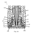
- Fig. 1B is a close up view of a portion of the assembly 100 shown Fig. 1A which better illustrates the coolant flow path 112 through the assembly in this embodiment.
- the coolant flow path 112 is defined by several surfaces of the center core 10, the cooling ring 11, and the thread core 12. Coolant flowing into the illustrated embodiment assembly, shown with a plus sign cross hatch, passes down through the bubbler tube 14 into the center core inlets 22 within the center core 10. Coolant flows out of the center core inlets 22 into the internal channels 23.
- the internal channels 23 are formed in the volume between longitudinal grooves in the inner surface of the cooling ring 11 and the outer surface of the center core 10.
- Coolant flows from the internal channels 23 into the traversing channels 24 that traverse wall of the cooling ring 11 from the inner surface of the cooling ring 11 to the outer surface of the cooling ring 11.
- the coolant may flow around the circumference of the cooling ring 11 in arcuate channels which direct the coolant to a return flow path through longitudinal flow paths formed by longitudinal grooves in the outer surface of the cooling ring 11, with the flow path being defined by the groove structure and an inner surface of the thread core 12.
- Fig. 1B also illustrates features of the thread core 12.
- the thread core 12 may include external threads 106 configured for molding the closure threads of caps.
- the thread core 12 may also include internal assembly threads 110.
- the center core 10 may be assembled through the cooling ring 11 and engage the assembly threads 110 of the thread core 12. Such assembly may hold the three pieces together and form the coolant channels there between. When assembled, a plug seal gap 108 between the cooling ring 11 and the center core 10 is formed into which compressed plastic material flows during pressing operations.
- Figs. 2 and 3 show the cooling ring 11 in isolation.
- the internal flow channels 23 are partially defined by grooves in the inner surface of the cooling ring 11.
- the other surface defining the internal channels 23 is the outer surface of the center core 10 when the center core 10 and cooling ring 11 are assembled together.
- the coolant flows vertically through the internal channels 23 formed between the center core 10 and the cooling ring 11 in the internal channels 23, and then radially outward through a plurality of traversing channels 24 that are holes passing through the wall of the cooling ring 11.
- Fig. 3 shows these arcuate channels 25 formed by grooves in the outside surface of cooling ring 11. The other surface defining the arcuate flow channels is the inside of the thread core 12 when the thread core 12 and cooling ring 11 are assembled together.
- These external longitudinal flow channels 26 are defined on one side by the longitudinal grooves labeled 26 on the outside of the cooling ring 11 and by the interior surfaces of the thread core 12 when the cooling ring 11 and thread core 12 are assembled together.
- Figs. 2 and 3 show an embodiment of the cooling ring 11 in which the ring is formed as a single component.
- the cooling ring may be an assembly comprising a plurality of components.
- a plurality of components may be joined or sealed together, such as with additional O-rings, to form a composite cooling ring.
- One or more of the plurality of components may define the various channels as described with regard to the cooling ring 11.
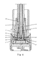
- Fig. 4 illustrates the same exemplary molding assembly 100 as Fig. 1A but at a different angle of rotation about the longitudinal axis in order to reveal the flow path of coolant exiting the mold assembly 100.
- the assembly 100 is shown in a first orientation that shows the coolant flows into the assembly.
- the assembly is rotated thirty degrees to show the coolant exit flow paths which are thirty degrees apart from the inner flow paths 23 about the cooling ring 11.
- coolant exits the traversing channels 24 and flows through the arcuate channels 25 around the cooling ring 11 before reaching external channels 26 where the flow is directed upward along the outer surface of the cooling ring 11.
- Coolant may flow from the external channels 26 into center core outlets 27.
- Multiple center core outlets 27 may be defined by surfaces inside the center core 10, similar to the center core inlets 22.
- the center core outlets 27 lead the coolant flow to the bubbler outlet 28 which directs the coolant flow out of the molding assembly 100.
- the bubbler outlet 28 flow path may pass through the volume defined by an outer surface of the bubbler tube 14 and an inner surface of the mandrel 36.
- coolant contacts the center core 10, cooling ring 11, and thread core 12 while passing through various volumes of the coolant flow path 112. This enables heat to be transferred from these parts to the coolant and removed from the assembly 100 as coolant flows out the bubbler outlet 28.
- stages in the coolant flow path 112 may include multiple channels. Multiple channels per stage may increase surface area contact with the parts and improve heat transfer.
- the multiple channels and flow paths may be designed or arranged to ensure an even heat distribution within the parts of the mold assembly, thereby preventing local hotspots from negatively affecting performance of the molding assembly 100 during high volume molding operations.
- the various channels of the coolant flow path 112 are sized with cross sectional areas designed to impart desirable coolant flow behavior.
- the combined cross sectional area of the plurality of center core inlets is greater than the cross sectional area of the bubbler inlet 21.
- the combined cross sectional area of the internal channels 23 is less than the cross sectional area of the bubbler inlet 21.
- the combined cross sectional area of the external channels 26 is less than the combined area of the internal channels 23.
- the ratios of cross sectional areas between portions of the flow path may be configured to control coolant flow and thereby improve heat transfer.
- Each successive element or stage may have a flow area ratio to the preceding stage configured to improve heat transfer in each stage.
- Each flow area ratio may be relative to the cross sectional area of the bubbler inlet 21 or to another stage in the coolant flow path 112.
- the center core inlets 23 may have a greater combined cross sectional area than other portions of the assembly.
- the subsequent portions of the coolant flow path through the upper assembly 102 may have a smaller combined cross sectional area corresponding with increased flow velocity and lower pressure with constant volumetric flow. Therefore, the coolant may experience a pressure gradient along the coolant flow path 112. This pressure gradient can be used to regulate the coolant flow through the upper assembly 102 and improve heat transfer from the mold elements to the coolant.
- Alternate embodiments may include differently shaped center cores, cooling rings, or thread cores. Embodiments that require more cooling may include a greater number of coolant channels. Alternatively, embodiments that require less cooling may include less coolant channels and thereby reduce the amount of coolant used. In further embodiments, some components illustrated and described herein as separate elements may be combined into single components exhibiting the same or similar features and performing the same or similar functions. Also, components illustrated and described herein as unitary structures may be formed as assemblies of multiple components.
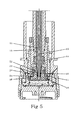
- Fig. 5 illustrates an alternate embodiment molding assembly.
- the embodiment assembly illustrated in Fig. 5 includes many of the same elements as the mold assembly 100 described above with reference Figures 1A , 1B 4 .
- the central core 10 and cooling ring 11 are configured differently so that the bottom of the center core 10 extends all the way to the thread core 12.
- This embodiment may not include the plug seal gaps 108 shown in Fig. 1B , and therefore the caps produced will not have a plug seal.
- a plug seal may be a seal to fit inside the lip of a container coupled with a cap.
- the cooling ring 11 may not directly contact the plastic material being molded. Heat may be transferred from the plastic material to the cooling ring 11 indirectly via the center core 10 or the thread core 12.
- Fig. 6 illustrates the embodiment of Fig. 5 rotated thirty degrees to show the coolant's exit path from the upper assembly 102.
- the assembly may not include plug seal gaps 108 and the cooling ring 11 may not be configured to contact the plastic material being molded.
- FIG. 7 illustrates an embodiment method 200 in which fluid coolant is directed into various elements of the coolant flow path 112.
- fluid coolant may be directed into or through a bubbler input in step 202, through a plurality of center core inlets in step 204, through a longitudinal flow path defined by plurality of internal grooves in the cooling ring in step 206, through a plurality of holes through the cooling ring in step 208, circumferentially through flow paths defined by a plurality of arcuate grooves in the cooling ring in step 210, through a longitudinal flow path defined by a plurality of external grooves in the cooling ring in step 212, through a plurality of center core outlets in step 214, and out of the assembly through a bubbler outlet in step 216.
- FIGS. 1A-6 illustrate flow paths in compression molding assembly embodiments, similar configurations and coolant flow paths may be included in injection molding assemblies in other embodiments.
- various embodiments may include injection molding assemblies through which a coolant fluid, such as water, flows into and out of a cooling ring around the molding assembly's core.
- Embodiment injection molding assemblies may include a coolant flow path such that fluid coolant may be directed into or through a bubbler input, through a plurality of center core inlets, through a longitudinal flow path defined by a plurality of internal grooves in the cooling ring, through a plurality of holes through the cooling ring, circumferentially through flow paths defined by a plurality of arcuate grooves in the cooling ring, through a longitudinal flow path defined by a plurality of external grooves in the cooling ring, through a plurality of center core outlets, and out of the assembly through a bubbler outlet.
- injection mold assemblies may include a plastic injection flow path through which the plastic material for forming the cap can be injected into the mold. The location and configuration of such a plastic injection flow within the mold assembly may vary and is not critical to the scope of the claims.
Landscapes
- Engineering & Computer Science (AREA)
- Mechanical Engineering (AREA)
- Manufacturing & Machinery (AREA)
- Physics & Mathematics (AREA)
- Fluid Mechanics (AREA)
- Moulds For Moulding Plastics Or The Like (AREA)
- Casting Or Compression Moulding Of Plastics Or The Like (AREA)
Description
- Compression molding is a known manufacturing process for producing molded objects from various plastics. Plastic material is placed in an open mold cavity. A plug or other forcing member then closes the mold and compresses the material to expand to the shape of the mold cavity. The mold opens and the part is ejected. The plastic material is generally preheated, sometimes above the melting point, to make the plastic material more flexible for molding. Once the plastic material is compressed into the form of the mold cavity, the molded plastic may be ejected and the cycle repeated. This process may be repeated frequently to make a large number of molded objects quickly. To enable high speed operation, the mold may be actively cooled. Exemplary injection/compression molding apparatuses and processes are described in
DE 10 2006 028 149 wherein the cooling insert shows a zig-zag path on the cooling surface andWO 00/48815 Fig.2 ). - According to a first aspect of the present invention, there is provided a molding device for molding a plastic material as claimed in claim 1. According to a second aspect of the present invention, there is provided a method of cooling a molding device with a fluid coolant as claimed in claim 5.
- Various embodiment assemblies include a compression or injection molding assembly for molding a plastic material featuring a coolant flow path including a plurality of stages, wherein at least one of the plurality of stages has a combined cross sectional area greater than the other stages, and wherein the coolant flow path is configured to cool a center core of the compression or injection molding assembly.
- Further embodiments include a compression or injection molding device for molding a plastic material including a bubbler with a bubbler inlet and a bubbler outlet, a center core located at an end of the bubbler with a plurality of center core inlets and a plurality of center core outlets, a cooling ring disposed around the center core with a plurality of internal grooves, a plurality of traversing channels, a plurality of arcuate grooves, and a plurality of external grooves, and a thread core disposed around the cooling ring, wherein the bubbler, the center core, the cooling ring, and the thread core are configured such that a fluid coolant may flow through the bubbler input, the plurality of center core inlets, a plurality of internal channels bounded by the plurality of internal grooves and the center core, the plurality of traversing channels, a plurality of arcuate channels bounded by the plurality of arcuate grooves and the thread core, a plurality of external channels bounded by the plurality of external grooves and the thread core, the plurality of center core outlets, and the bubbler outlet.
- Further embodiments include a method for cooling a compression or injection molding device with a fluid coolant, the compression or injection molding device including a bubbler, a center core, a cooling ring, and a thread core. The method includes directing the fluid coolant into a bubbler inlet of the bubbler, directing the fluid coolant into a plurality of center core inlets of the center core, directing the fluid coolant into a plurality of internal channels bounded by a plurality of internal channels of the cooling ring and the center core, directing the fluid coolant into a plurality of traversing channels of the cooling ring, directing the fluid coolant into a plurality of arcuate channels bounded by a plurality of arcuate grooves of the cooling ring and the thread core, directing the fluid coolant into a plurality of external grooves of the cooling ring, directing the fluid coolant into a plurality of center core outlets of the center core, and directing the fluid coolant into a bubbler outlet of the bubbler.
- The accompanying drawings, which are incorporated herein and constitute part of this specification, illustrate exemplary embodiments of the invention, and, together with the general description given above and the detailed description given below, serve to explain features of the invention.
-
Fig. 1A is a cross sectional view of a cavity stack showing a coolant flow path into the stack. -
Fig. 1B is a close up view of the coolant flow path in the cavity stack ofFig. 1A . -
Fig. 2 is a perspective view of a cooling ring viewed from the bottom. -
Fig. 3 is a perspective view of a cooling ring viewed from the top. -
Fig. 4 is a cross sectional view of the cavity stack fromFig. 1A but rotated thirty degrees to show a coolant flow path out of the stack. -
Fig. 5 is a cross sectional view of a cavity stack for producing a cap without a plug seal showing a coolant flow path into the stack. -
Fig. 6 is a cross sectional view of the cavity stack fromFig. 5 but rotated thirty degrees to show a coolant flow path out of the stack. -
Fig. 7 is a process flow diagram of an embodiment method for cooling a compression or injection molding device. - The present assemblies, devices, and methods will be described in more detail hereinafter with reference to the accompanying drawings, in which embodiments of the inventions are shown. The present embodiments are provided so that the subject disclosure will be thorough and complete, and will convey the scope of the invention to those skilled in the art. Like numbers refer to like elements throughout.
- The following is a list of numbers and their associated elements that appear in the drawings and the following description of the various embodiments:
- 10
- Center Core
- 11
- Cooling Ring
- 12
- Thread Core
- 13
- Tamper Band Core
- 14
- Bubbler Tube
- 15
- Air Tube
- 16
- Air Plug
- 17
- O-Ring - Center Core
- 18
- O-Ring - Cooling Ring
- 19
- O-Ring - Mandrel
- 20
- O-Ring - Air Plug
- 21
- Coolant Flow Path - Bubbler Inlet
- 22
- Coolant Flow Path - Center Core Inlet
- 23
- Coolant Flow Path - Internal Channels in Cooling Ring
- 24
- Coolant Flow Path - Traversing Channels in Cooling Ring
- 25
- Coolant Flow Path - Arcuate Channels in Cooling Ring
- 26
- Coolant Flow Path - External Channels in Cooling Ring
- 27
- Coolant Flow Path - Center Core Outlet
- 28
- Coolant Flow Path - Bubbler Outlet
- 29
- Stripper
- 30
- Cavity
- 31
- Outer Ring
- 32
- Cavity Bottom
- 33
- Cover Plate
- 34
- Adapter
- 35
- Machine Nut
- 36
- Mandrel
- 100
- Compression Molding Assembly
- 102
- Upper Assembly
- 104
- Base Assembly
- 106
- External Threads of the Thread Core
- 108
- Plug Seal Gaps
- 110
- Internal Assembly Threads of the Thread Core
- 112
- Coolant Flow Path
- In this description, the term "exemplary" is used herein to mean "serving as an example, instance, or illustration." Any implementation described herein as "exemplary" is not necessarily to be construed as preferred or advantageous over other implementations.
- The various embodiments provide methods and devices for cooling a compression or injection molding assembly, thereby enabling increased cycling speed and efficiency. Embodiments provide coolant flow paths through a mold assembly through which a coolant fluid (e.g., water) flows into and out of a cooling ring around the molding assembly's core. The coolant flow path may divide into several channels within and around the cooling ring to enable efficient heat transfer and more uniform thermal profiles within the mold assembly than achieved in conventional designs. The coolant flow path may include a series of stages with varying volumes or cross sectional dimensions configured to regulate the flow of coolant. Embodiment methods and devices may enable greater production rates with lower coolant flow rates.
-
Fig. 1A is a cross sectional view of an embodimentcompression molding assembly 100 that may be used for molding plastic caps.Molding assembly 100 may comprise anupper assembly 102 and abase assembly 104. Theupper assembly 102 may include may include a stripper 29, atamper band core 13, athread core 12, acooling ring 11, acenter core 10, and amandrel 36. - In operation, the
center core 10 may contact and compress a plastic material (not shown). A coolingring 11 is configured around thecenter core 10. A first end of athread core 12 is configured around thecooling ring 11. Thethread core 12, coolingring 11, andcenter core 10 are concentric about a central axis as shown inFig. 1A . - A second end of the
thread core 12 may be assembled about amandrel 36. In the embodiment illustrated inFig. 1A , thethread core 12 is positioned within atamper band core 13 which forms tamper bands of the caps. However, thetamper band core 13 is optional, and an embodiment without this component is described below with reference toFigures 5 and6 . Thetamper band core 13 may be assembled within a stripper 29, which may push a formed cap from themold assembly 100 after the cap is formed. In operation thebase assembly 104 may move relative toupper assembly 102 to compress plastic material within the volume between the two assemblies. - The
base assembly 104 may include acavity 30 with a cavity bottom 32. During operation, plastic material may be loaded within thecavity 30 and compressed by moving the upper or base assemblies relative to one another. Typically, theupper assembly 102 is threaded into a carousel while thebase assembly 104 is attached to a press mechanism (e.g., a hydraulic ram) that raises and lowers the base assembly with respect to theupper assembly 102. The compressed plastic material assumes the shape of the open space within the mold cavity between thebase assembly 104 andupper assembly 102. For example, in theassembly 100 ofFig. 1A the compressed plastic material fills the boundaries of thecavity 30 and cavity bottom 32. - The
base assembly 104 may also include an outer ring 31and a cover plate 33. Thebase assembly 104 may be loaded onto an adapter 34, which may be threaded into a support or press mechanism. A machine nut 35 may include a lip that fits around the outer ring 31 and acts to retain thebase assembly 104 with the support or press mechanism. - The
upper mold assembly 102 shown inFig. 1A includes abubbler tube 14 and an air tube 15 within themandrel 36. The air tube 15 and thebubbler tube 14 may be concentric about the longitudinal axis of themandrel 36 with the air tube 15 disposed within thebubbler tube 14. The air tube 15 may extend to anair plug 16 within thecenter core 10. Air pressure may be applied through the air tube 15 and intoair plug 16. During operation, air directed by theair plug 16 may be used to aid ejection of a molded plastic cap off of thecenter core 10, such as by preventing formation of a vacuum between the molded cap and theupper assembly 102. - Coolant, such as water or other fluids, is supplied through the
bubbler inlet 21. The bubbler inlet may be defined by interior surfaces of thebubbler tube 14 and exterior surfaces of the air tube 15. Thebubbler tube 14 may be configured to keep air and other gases out of the coolant. Coolant flows from thebubbler inlet 21 to a plurality ofcenter core inlets 22. The multiplecenter core inlets 22 one defined by surfaces inside thecenter core 10. During operation, coolant flows from thecenter core inlets 22 intointernal channels 23 adjacent thecooling ring 11, with theinternal channels 23 defined by the outer surface of the center core and a plurality of grooves in the inner surface of thecooling ring 11. Coolant flows then into traversingchannels 24 defined by a plurality of holes extending radially from an inner surface to an outer surface of thecooling ring 11. The orientation of the grooves forming theinternal channels 23 and the traversingchannels 24 in thecooling ring 11 are described in more detail below with reference toFigs. 2 and 3 . - To seal the coolant flow paths through the several parts to prevent leaks and air ingress, the
assembly 100 may also include a number of O-ring seals between the various parts. For example, inFig. 1A , the center core O-ring 17 forms a seal between thecenter core 10 and thecooling ring 11 preventing leakage of coolant flowing ininternal channels 23 or enteringtraverse channels 24. Similarly, the cooling ring O-ring 18 forms a seal between thethread core 12 and thecooling ring 11 preventing leakage of coolant flowing in external channels 25 or exitingtraverse channels 24. A mandrel O-ring 19 may form seal at the top of thethread core 12. An air plug O-ring 20 may prevent coolant in thecenter core inlets 22 from entering the air plug and prevent air from entering the coolant. -
Fig. 1B is a close up view of a portion of theassembly 100 shownFig. 1A which better illustrates thecoolant flow path 112 through the assembly in this embodiment. Thecoolant flow path 112 is defined by several surfaces of thecenter core 10, the coolingring 11, and thethread core 12. Coolant flowing into the illustrated embodiment assembly, shown with a plus sign cross hatch, passes down through thebubbler tube 14 into thecenter core inlets 22 within thecenter core 10. Coolant flows out of thecenter core inlets 22 into theinternal channels 23. Theinternal channels 23 are formed in the volume between longitudinal grooves in the inner surface of thecooling ring 11 and the outer surface of thecenter core 10. Coolant flows from theinternal channels 23 into the traversingchannels 24 that traverse wall of thecooling ring 11 from the inner surface of thecooling ring 11 to the outer surface of thecooling ring 11. Upon exiting the traversingchannels 24, the coolant may flow around the circumference of thecooling ring 11 in arcuate channels which direct the coolant to a return flow path through longitudinal flow paths formed by longitudinal grooves in the outer surface of thecooling ring 11, with the flow path being defined by the groove structure and an inner surface of thethread core 12. -
Fig. 1B also illustrates features of thethread core 12. Thethread core 12 may includeexternal threads 106 configured for molding the closure threads of caps. Thethread core 12 may also includeinternal assembly threads 110. Thecenter core 10 may be assembled through thecooling ring 11 and engage theassembly threads 110 of thethread core 12. Such assembly may hold the three pieces together and form the coolant channels there between. When assembled, aplug seal gap 108 between the coolingring 11 and thecenter core 10 is formed into which compressed plastic material flows during pressing operations. -
Figs. 2 and 3 show thecooling ring 11 in isolation. Referring toFig. 2 , theinternal flow channels 23 are partially defined by grooves in the inner surface of thecooling ring 11. The other surface defining theinternal channels 23 is the outer surface of thecenter core 10 when thecenter core 10 andcooling ring 11 are assembled together. As discussed above, the coolant flows vertically through theinternal channels 23 formed between thecenter core 10 and thecooling ring 11 in theinternal channels 23, and then radially outward through a plurality of traversingchannels 24 that are holes passing through the wall of thecooling ring 11. - Referring to
Fig. 3 , coolant flowing from inside the coolingring 11 through the traversingchannels 24 flows into one or more arcuate channels 25 passing around the outside of thecooling ring 11.Fig. 3 shows these arcuate channels 25 formed by grooves in the outside surface of coolingring 11. The other surface defining the arcuate flow channels is the inside of thethread core 12 when thethread core 12 andcooling ring 11 are assembled together. Coolant flow through the arcuate channels 25 to a plurality oflongitudinal flow channels 26 on the outer surface of thecooling ring 11. These externallongitudinal flow channels 26 are defined on one side by the longitudinal grooves labeled 26 on the outside of thecooling ring 11 and by the interior surfaces of thethread core 12 when thecooling ring 11 andthread core 12 are assembled together. -
Figs. 2 and 3 show an embodiment of thecooling ring 11 in which the ring is formed as a single component. However, in other embodiments the cooling ring may be an assembly comprising a plurality of components. For example, a plurality of components may be joined or sealed together, such as with additional O-rings, to form a composite cooling ring. One or more of the plurality of components may define the various channels as described with regard to thecooling ring 11. -
Fig. 4 illustrates the sameexemplary molding assembly 100 asFig. 1A but at a different angle of rotation about the longitudinal axis in order to reveal the flow path of coolant exiting themold assembly 100. InFigs. 1A and1B , theassembly 100 is shown in a first orientation that shows the coolant flows into the assembly. InFig. 4 , the assembly is rotated thirty degrees to show the coolant exit flow paths which are thirty degrees apart from theinner flow paths 23 about thecooling ring 11. As shown inFig. 4 , in this embodiment coolant exits the traversingchannels 24 and flows through the arcuate channels 25 around thecooling ring 11 before reachingexternal channels 26 where the flow is directed upward along the outer surface of thecooling ring 11. Again, details on the grooves in the cooling ring forming theexternal flow channels 26 are shown inFigures 2 and 3 , including how these flow channels are offset from each other by an angle about the longitudinal axis. In the embodiment illustrated in the figures, this offset angle is approximately thirty degrees, but the angle may vary depending on the number of coolant channels in each stage of the assembly. - Coolant may flow from the
external channels 26 intocenter core outlets 27. Multiplecenter core outlets 27 may be defined by surfaces inside thecenter core 10, similar to thecenter core inlets 22. Thecenter core outlets 27 lead the coolant flow to thebubbler outlet 28 which directs the coolant flow out of themolding assembly 100. Thebubbler outlet 28 flow path may pass through the volume defined by an outer surface of thebubbler tube 14 and an inner surface of themandrel 36. - In the embodiment illustrated in the figures, coolant contacts the
center core 10, coolingring 11, andthread core 12 while passing through various volumes of thecoolant flow path 112. This enables heat to be transferred from these parts to the coolant and removed from theassembly 100 as coolant flows out thebubbler outlet 28. Several stages in thecoolant flow path 112 may include multiple channels. Multiple channels per stage may increase surface area contact with the parts and improve heat transfer. The multiple channels and flow paths may be designed or arranged to ensure an even heat distribution within the parts of the mold assembly, thereby preventing local hotspots from negatively affecting performance of themolding assembly 100 during high volume molding operations. - The various channels of the
coolant flow path 112 are sized with cross sectional areas designed to impart desirable coolant flow behavior. The combined cross sectional area of the plurality of center core inlets is greater than the cross sectional area of thebubbler inlet 21. The combined cross sectional area of theinternal channels 23 is less than the cross sectional area of thebubbler inlet 21. The combined cross sectional area of theexternal channels 26 is less than the combined area of theinternal channels 23. These dimensional parameters can ensure even flow through theupper mold assembly 102 during operation. - The ratios of cross sectional areas between portions of the flow path may be configured to control coolant flow and thereby improve heat transfer. Each successive element or stage may have a flow area ratio to the preceding stage configured to improve heat transfer in each stage. Each flow area ratio may be relative to the cross sectional area of the
bubbler inlet 21 or to another stage in thecoolant flow path 112. For example, in an assembly with the flow area ratios described above, thecenter core inlets 23 may have a greater combined cross sectional area than other portions of the assembly. The subsequent portions of the coolant flow path through theupper assembly 102 may have a smaller combined cross sectional area corresponding with increased flow velocity and lower pressure with constant volumetric flow. Therefore, the coolant may experience a pressure gradient along thecoolant flow path 112. This pressure gradient can be used to regulate the coolant flow through theupper assembly 102 and improve heat transfer from the mold elements to the coolant. - Alternate embodiments may include differently shaped center cores, cooling rings, or thread cores. Embodiments that require more cooling may include a greater number of coolant channels. Alternatively, embodiments that require less cooling may include less coolant channels and thereby reduce the amount of coolant used. In further embodiments, some components illustrated and described herein as separate elements may be combined into single components exhibiting the same or similar features and performing the same or similar functions. Also, components illustrated and described herein as unitary structures may be formed as assemblies of multiple components.
-
Fig. 5 illustrates an alternate embodiment molding assembly. The embodiment assembly illustrated inFig. 5 includes many of the same elements as themold assembly 100 described above with referenceFigures 1A ,1B 4 . However, in the embodiment illustrated inFig. 5 , thecentral core 10 andcooling ring 11 are configured differently so that the bottom of thecenter core 10 extends all the way to thethread core 12. This embodiment may not include theplug seal gaps 108 shown inFig. 1B , and therefore the caps produced will not have a plug seal. A plug seal may be a seal to fit inside the lip of a container coupled with a cap. In this embodiment, the coolingring 11 may not directly contact the plastic material being molded. Heat may be transferred from the plastic material to thecooling ring 11 indirectly via thecenter core 10 or thethread core 12. -
Fig. 6 illustrates the embodiment ofFig. 5 rotated thirty degrees to show the coolant's exit path from theupper assembly 102. As inFig. 5 , the assembly may not includeplug seal gaps 108 and thecooling ring 11 may not be configured to contact the plastic material being molded. - Further embodiments include methods of cooling a molding assembly. These embodiment methods may include directing fluid coolant through one or more of the structures discussed above while forming plastic parts by compression or injection molding.
Fig. 7 illustrates anembodiment method 200 in which fluid coolant is directed into various elements of thecoolant flow path 112. Specifically, fluid coolant may be directed into or through a bubbler input instep 202, through a plurality of center core inlets instep 204, through a longitudinal flow path defined by plurality of internal grooves in the cooling ring instep 206, through a plurality of holes through the cooling ring instep 208, circumferentially through flow paths defined by a plurality of arcuate grooves in the cooling ring instep 210, through a longitudinal flow path defined by a plurality of external grooves in the cooling ring instep 212, through a plurality of center core outlets instep 214, and out of the assembly through a bubbler outlet instep 216. - Further embodiments include injection molding assemblies with coolant flow paths as described herein. Although
FIGS. 1A-6 illustrate flow paths in compression molding assembly embodiments, similar configurations and coolant flow paths may be included in injection molding assemblies in other embodiments. For example, various embodiments may include injection molding assemblies through which a coolant fluid, such as water, flows into and out of a cooling ring around the molding assembly's core. Embodiment injection molding assemblies may include a coolant flow path such that fluid coolant may be directed into or through a bubbler input, through a plurality of center core inlets, through a longitudinal flow path defined by a plurality of internal grooves in the cooling ring, through a plurality of holes through the cooling ring, circumferentially through flow paths defined by a plurality of arcuate grooves in the cooling ring, through a longitudinal flow path defined by a plurality of external grooves in the cooling ring, through a plurality of center core outlets, and out of the assembly through a bubbler outlet. Additionally, injection mold assemblies may include a plastic injection flow path through which the plastic material for forming the cap can be injected into the mold. The location and configuration of such a plastic injection flow within the mold assembly may vary and is not critical to the scope of the claims. - The foregoing description of the various embodiments is provided to enable any person skilled in the art to make or use the present invention. Various modifications to these embodiments will be readily apparent to those skilled in the art, and the generic principles defined herein may be applied to other embodiments without departing from the scope of the invention. Thus, the present invention is not intended to be limited to the embodiments shown herein, but it is defined by the scope of the appended claims.
Claims (5)
- A molding device for molding a plastic material, comprising:a center core (10) comprising a plurality of center core inlets (22) and a plurality of center core outlets (27);a bubbler (14) coupled with the center core (10) and comprising a bubbler inlet (21) and a bubbler outlet (28), wherein the bubbler (14) is configured to further define a fluid coolant flow path (112) so that coolant flows in through the bubbler inlet (21) through to the center core inlets (22), and wherein the bubbler (14) is configured to further define the fluid coolant flow path (112) so that coolant flows from the center core outlets (27) and out through the bubbler outlet (28);a cooling ring (11) disposed around the center core (10), the cooling ring (11) comprising a plurality of internal grooves, a plurality of traversing channels (24), a plurality of arcuate grooves (25), and a plurality of external grooves; anda thread core (12) disposed around the cooling ring (11);wherein the center core (10), the cooling ring (11), and the thread core (12) are configured to define a fluid coolant flow path (112) through which coolant may flow into the plurality of center core inlets (22), through a plurality of internal channels (23) bounded by the plurality of internal grooves and the center core (10), through the plurality of traversing channels (24), through a plurality of arcuate channels (25) bounded by the plurality of arcuate grooves and the thread core (12), through a plurality of external channels (26) bounded by the plurality of external grooves and the thread core (12), and through the plurality of center core outlets (27);wherein the center core (10), the cooling ring (11), and the thread core (12) are configured to define the fluid coolant flow path (112) with cross sectional areas configured to control the coolant flow;wherein the center core (10) is configured to define the plurality of center core inlets (22) with a greater combined cross sectional area than the bubbler inlet (21);wherein the center core (10) and the cooling ring (11) are configured to define the plurality of internal channels (23) with a smaller combined cross sectional area than the bubbler inlet (21); andwherein the thread core (12) and the cooling ring (11) are configured to define the plurality of external channels (26) with a smaller combined cross sectional area than the plurality of internal channels (23).
- The molding device of claim 1, wherein:the center core (10) is configured to mold caps; and/orthe thread core (12) comprises external threads.
- The molding device of claim 2, wherein the cooling ring (11) is configured to directly contact the plastic material during a molding operation.
- The molding device of claim 1, wherein the molding device is an injection molding device or a compression molding device.
- A method of cooling a molding device with a fluid coolant, the molding device comprising a bubbler (14), a center core (10), a cooling ring (11), and a thread core (12), the method comprising:configuring the center core (10), the cooling ring (11), and the thread core (12) to define a fluid coolant flow path (112) with cross sectional areas configured to control the coolant flow by:disposing the cooling ring (11) around the center core (10);configuring the center core (10) to define a plurality of center core inlets (22) with a greater combined cross sectional area than a bubbler inlet (21);configuring the center core (10) and the cooling ring (11) to define a plurality of internal channels (23) with a smaller combined cross sectional area than the bubbler inlet (21); andconfiguring the thread core (12) and the cooling ring (11) to define a plurality of external channels (26) with a smaller combined cross sectional area than the plurality of internal channels (23); the method further comprising:directing the fluid coolant into the bubbler inlet (21) of the bubbler (14);directing the fluid coolant from the bubbler (14) into the plurality of center core inlets (22) of the center core (10);directing the fluid coolant from the center core inlets (22) into the plurality of internal channels (23) bounded by a plurality of internal grooves of the cooling ring (11) and the center core (10);directing the fluid coolant from the plurality of internal channels (23) into a plurality of traversing channels (24) of the cooling ring (11);directing the fluid coolant from the plurality of traversing channels (24) into a plurality of arcuate channels (25) bounded by a plurality of arcuate grooves of the cooling ring (11) and the thread core (12);directing the fluid coolant from the plurality of arcuate channels (25) into the plurality of external channels (26) defined by external grooves of the cooling ring (11) and the thread core (12);directing the fluid coolant from the plurality of external channels (26) into a plurality of center core outlets (27) of the center core (10); anddirecting the fluid coolant from the plurality of center core outlets (27) into a bubbler outlet (28) of the bubbler (14) and out of the molding device.
Applications Claiming Priority (3)
| Application Number | Priority Date | Filing Date | Title |
|---|---|---|---|
| US13/114,327 US20120301570A1 (en) | 2011-05-24 | 2011-05-24 | Compression Molding with Successive Cooling Channels |
| US13/277,022 US8585392B2 (en) | 2011-05-24 | 2011-10-19 | Compression molding with successive stage cooling channels |
| PCT/US2012/037985 WO2012162035A2 (en) | 2011-05-24 | 2012-05-15 | Molding device with successive stage cooling channels |
Publications (3)
| Publication Number | Publication Date |
|---|---|
| EP2714356A2 EP2714356A2 (en) | 2014-04-09 |
| EP2714356A4 EP2714356A4 (en) | 2014-11-05 |
| EP2714356B1 true EP2714356B1 (en) | 2016-01-13 |
Family
ID=47217972
Family Applications (1)
| Application Number | Title | Priority Date | Filing Date |
|---|---|---|---|
| EP12790229.4A Active EP2714356B1 (en) | 2011-05-24 | 2012-05-15 | Molding device with successive stage cooling channels |
Country Status (13)
| Country | Link |
|---|---|
| US (2) | US8585392B2 (en) |
| EP (1) | EP2714356B1 (en) |
| JP (1) | JP6085295B2 (en) |
| KR (1) | KR101946589B1 (en) |
| CN (1) | CN103946001B (en) |
| AU (1) | AU2012259212B2 (en) |
| CA (1) | CA2836572C (en) |
| ES (1) | ES2568066T3 (en) |
| HK (1) | HK1199227A1 (en) |
| HU (1) | HUE028491T2 (en) |
| MX (1) | MX344506B (en) |
| WO (1) | WO2012162035A2 (en) |
| ZA (1) | ZA201309266B (en) |
Cited By (1)
| Publication number | Priority date | Publication date | Assignee | Title |
|---|---|---|---|---|
| US11420378B2 (en) | 2018-12-07 | 2022-08-23 | Nalge Nunc International Corporation | Core rod assembly for blow molding and having multiple temperature zones |
Families Citing this family (11)
| Publication number | Priority date | Publication date | Assignee | Title |
|---|---|---|---|---|
| US8585392B2 (en) * | 2011-05-24 | 2013-11-19 | F&S Tool, Inc. | Compression molding with successive stage cooling channels |
| US9248597B2 (en) * | 2012-04-02 | 2016-02-02 | Progressive Components International Corporation | Bubbler base |
| US10005214B1 (en) * | 2014-07-03 | 2018-06-26 | Plastek Industries, Inc. | Cap manufacture methods and apparatus |
| MX2017008332A (en) | 2014-12-22 | 2017-11-28 | Graham Packaging Co | Deformation-resistant container with panel indentations. |
| IT201600076240A1 (en) | 2016-07-20 | 2018-01-20 | Sacmi | PUNCH FOR COMPRESSION MOLDS |
| CN112601623A (en) * | 2018-08-24 | 2021-04-02 | 格鲁帕铸造有限责任公司 | Molding tool with high performance cooling system |
| US20230210659A1 (en) | 2020-06-03 | 2023-07-06 | Medtronic, Inc. | Delivery device having a control release shaft for improved positioning of a transcatheter heart valve |
| US20230210660A1 (en) | 2020-06-04 | 2023-07-06 | Medtronic, Inc. | Delivery system having a split distal tip for improved positioning of a transcatheter heart valve |
| US11794938B2 (en) | 2021-09-02 | 2023-10-24 | Graham Packaging Company, L.P. | Container finish having improved rim planarity |
| CN114472969B (en) * | 2022-03-25 | 2023-04-18 | 苏州凯雷特精密机械有限公司 | Drilling device for aerospace parts |
| US20230364845A1 (en) * | 2022-05-16 | 2023-11-16 | Engineered Profiles LLC | Clad sizer for an extrusion machine |
Family Cites Families (63)
| Publication number | Priority date | Publication date | Assignee | Title |
|---|---|---|---|---|
| US2828509A (en) * | 1954-11-03 | 1958-04-01 | Crown Machine And Tool Company | Plastic molding machines |
| US3373479A (en) | 1965-03-25 | 1968-03-19 | Aluminum Co Of America | Method for making molded articles |
| US3660001A (en) | 1968-11-06 | 1972-05-02 | George L Roehr | Molding apparatus with positive collapse core |
| DE2255644B2 (en) | 1972-11-14 | 1975-01-09 | Karl Schmidt Gmbh, 7107 Neckarsulm | Method and mold for casting piston blanks |
| US4091069A (en) * | 1977-02-17 | 1978-05-23 | Logic Devices, Inc. | Method and apparatus for venting entrapped air in mold cavities |
| US4130264A (en) | 1977-10-26 | 1978-12-19 | Geyer & Co. | Expandable core for injection molding |
| JPS57156231A (en) | 1981-03-23 | 1982-09-27 | Hitachi Ltd | Split core of mold for injection molding |
| US4533312A (en) | 1982-12-27 | 1985-08-06 | Holdt J W Von | Simplified collapsible mold core |
| JPS59150715A (en) | 1983-02-16 | 1984-08-29 | Daiichi Gaiyaa Kk | Mold material |
| JPS60112413A (en) | 1983-11-25 | 1985-06-18 | Daiichi Gaiyaa Kk | Pop-up core |
| US4622001A (en) | 1985-03-12 | 1986-11-11 | Electra Form, Inc. | Cavity cooling system |
| DE3666178D1 (en) | 1985-08-30 | 1989-11-16 | Clarke & Co Moulds Ltd R | Collapsible mould core |
| US4731014A (en) | 1986-03-12 | 1988-03-15 | Holdt J W Von | Rear opening mold |
| JPS62279914A (en) | 1986-05-28 | 1987-12-04 | Cosmo Seimitsu:Kk | Manufacturing equipment for article having undercut on inside |
| JPH0622838B2 (en) * | 1987-07-22 | 1994-03-30 | 富士写真フイルム株式会社 | Injection mold |
| JP2585601B2 (en) | 1987-06-05 | 1997-02-26 | 東陶機器株式会社 | Core structure for molding equipment |
| EP0311711A1 (en) | 1987-10-16 | 1989-04-19 | KLEVOTEC Gesellschaft für rechnergestützte Systemanwendungen mbH&Co.KG | Method for sintering moulded undercut foam articles |
| US5114655A (en) | 1989-08-17 | 1992-05-19 | Cole Machine & Mfg. Co. | Method and apparatus for injection molding |
| US5096410A (en) | 1991-02-19 | 1992-03-17 | Demetre Loulourgas | Water jacketed sprue bushing |
| JPH07106583B2 (en) | 1991-09-03 | 1995-11-15 | 株式会社コパル | Injection mold with undercut |
| DE4234961C2 (en) * | 1992-10-16 | 1996-07-25 | Innova Zug Ag | Process for producing a mold for the production of plastic molded parts |
| US5383780A (en) | 1993-09-27 | 1995-01-24 | Husky Injection Molding Systems Ltd. | Apparatus for forming threaded molded article |
| US5798074A (en) | 1993-09-27 | 1998-08-25 | Husky Injection Molding Systems Ltd. | Process for forming a threaded molded plastic article |
| US5403179A (en) | 1993-10-29 | 1995-04-04 | Ramsey; William C. | Collapsible mold core assembly |
| US5387389A (en) | 1993-12-23 | 1995-02-07 | Roehr Tool Corporation | Injection molding method and system with expandable cavity element |
| JP2869854B2 (en) | 1994-10-19 | 1999-03-10 | 株式会社トスカ | Synthetic resin molding method and apparatus |
| CA2148966C (en) | 1995-02-09 | 1997-03-04 | Werner Scheliga | Seamless molded skirt and process |
| JPH09262870A (en) * | 1996-01-23 | 1997-10-07 | Sekisui Chem Co Ltd | Injection mold and its production |
| US5935621A (en) | 1997-01-24 | 1999-08-10 | Mold-Masters Limited | Injection molding apparatus having a cooled core |
| USRE38265E1 (en) * | 1997-01-24 | 2003-10-07 | Mold-Masters Limited | Injection molding apparatus having a cooled core |
| CA2494248A1 (en) | 1997-04-16 | 1998-10-22 | Husky Injection Molding Systems Ltd. | Partial crystallization method and apparatus of amorphous plastic articles |
| KR19990018904U (en) | 1997-11-14 | 1999-06-05 | 오상수 | Cooling water circulation structure of mold |
| CA2228458C (en) * | 1998-02-02 | 2008-08-05 | Mold-Masters Limited | Injection molding cooled gate insert |
| CA2228931C (en) | 1998-02-02 | 2007-06-26 | Mold-Masters Limited | Injection molding three portion gate and cavity insert |
| US6099785A (en) | 1998-03-17 | 2000-08-08 | Schweigert; Lothar | Method for injection molding plastic closures |
| US6506330B1 (en) | 1998-03-17 | 2003-01-14 | Lothar Schweigert | Apparatus and method for molding plastic closures |
| CA2255800C (en) * | 1998-12-07 | 2008-06-10 | Jobst Ulrich Gellert | Injection molding cooling core having a ribbed cap |
| CA2255798C (en) * | 1998-12-07 | 2008-06-17 | Jobst Ulrich Gellert | Injection molding cooling core having spiral grooves |
| US6220850B1 (en) | 1999-02-16 | 2001-04-24 | Husky Injection Molding Systems Ltd. | Mold gate insert |
| CA2262176C (en) * | 1999-02-17 | 2008-04-22 | Jobst Ulrich Gellert | Injection molding cooled cavity insert |
| US6276922B1 (en) * | 1999-08-24 | 2001-08-21 | Husky Injection Molding Systems Ltd. | Core fluid velocity inducer |
| US6491175B1 (en) | 2000-06-28 | 2002-12-10 | Saad Taha | Single piece closure for a pressurized container |
| US6903308B2 (en) | 2000-11-01 | 2005-06-07 | Gordon M. Pendergraft | Vacuum cast ceramic fiber insulated band having heating and cooling elements |
| CA2401931A1 (en) * | 2001-09-07 | 2003-03-07 | Dennis S. Byrnes | Mold with contoured cooling channels |
| ITRE20030005A1 (en) | 2003-01-20 | 2004-07-21 | Sacmi | METHOD FOR FORMING OBJECTS BY MOLDING |
| US7232306B2 (en) | 2003-08-22 | 2007-06-19 | Graham Packaging Company, Lp | Modified injection takeout tube |
| US7234930B2 (en) * | 2004-06-14 | 2007-06-26 | Husky Injection Molding Systems Ltd. | Cooling circuit for cooling neck ring of preforms |
| ES2317315T3 (en) | 2004-10-13 | 2009-04-16 | Sacmi Cooperativa Meccanici Imola Societa' Cooperativa | COVER TO CLOSE CONTAINERS AND APPARATUS TO FORM COATINGS. |
| US20060188601A1 (en) | 2005-02-18 | 2006-08-24 | Mr. Garry Zydron | Collapsible core using two sleeves and is spring loaded |
| US7252497B2 (en) | 2005-03-10 | 2007-08-07 | Husky Injection Molding Systems Ltd. | Post-molding molded article conditioning apparatus with a selectively controlled transfer flow structure |
| US7431582B2 (en) | 2005-06-17 | 2008-10-07 | Rexam Closure Systems Inc. | Molding machine |
| ITMO20050224A1 (en) | 2005-09-07 | 2007-03-08 | Sacmi | MOLDS FOR MOLDING OF PLASTIC ITEMS AND METHOD TO PRODUCE A MOLD ELEMENT |
| US7361009B2 (en) | 2005-10-20 | 2008-04-22 | Husky Injection Molding Systems Ltd. | Mold cavity insert for use in an injection mold |
| US7381049B2 (en) | 2006-03-08 | 2008-06-03 | Husky Injection Molding Systems Ltd. | Injection mold |
| DE102006021228A1 (en) | 2006-05-06 | 2007-11-08 | Mht Mold & Hotrunner Technology Ag | Two-piece ground insert |
| DE102006021229A1 (en) | 2006-05-06 | 2007-11-15 | Mht Mold & Hotrunner Technology Ag | Floor insert with heat insulation |
| DE102006028149A1 (en) | 2006-06-16 | 2007-12-20 | Mht Mold & Hotrunner Technology Ag | Formnestkavität with decoupled cooling duct guide |
| US20090152770A1 (en) | 2007-08-07 | 2009-06-18 | Canon Virginia Inc. | Mechanically collapsible core for injection molding |
| US7645132B2 (en) | 2007-09-07 | 2010-01-12 | Husky Injection Molding Systems Ltd. | Mold insert and mold stack for use with molding machine |
| JP2009196138A (en) * | 2008-02-20 | 2009-09-03 | Seiko Epson Corp | Apparatus for injection moulding and cooling method in apparatus for injection moulding |
| EP3072665B1 (en) | 2009-01-22 | 2018-09-05 | Mold-Masters (2007) Limited | Injection molding apparatus |
| US8585392B2 (en) * | 2011-05-24 | 2013-11-19 | F&S Tool, Inc. | Compression molding with successive stage cooling channels |
| ITMO20120072A1 (en) * | 2012-03-21 | 2013-09-22 | Ativa | MALE PIECE ELEMENT. |
-
2011
- 2011-10-19 US US13/277,022 patent/US8585392B2/en active Active
-
2012
- 2012-05-15 EP EP12790229.4A patent/EP2714356B1/en active Active
- 2012-05-15 JP JP2014512878A patent/JP6085295B2/en active Active
- 2012-05-15 AU AU2012259212A patent/AU2012259212B2/en active Active
- 2012-05-15 ES ES12790229.4T patent/ES2568066T3/en active Active
- 2012-05-15 KR KR1020137033950A patent/KR101946589B1/en active IP Right Grant
- 2012-05-15 HU HUE12790229A patent/HUE028491T2/en unknown
- 2012-05-15 CN CN201280030178.XA patent/CN103946001B/en active Active
- 2012-05-15 CA CA2836572A patent/CA2836572C/en active Active
- 2012-05-15 WO PCT/US2012/037985 patent/WO2012162035A2/en active Application Filing
- 2012-05-15 MX MX2013013506A patent/MX344506B/en active IP Right Grant
-
2013
- 2013-10-09 US US14/049,568 patent/US9475246B2/en active Active
- 2013-12-09 ZA ZA2013/09266A patent/ZA201309266B/en unknown
-
2014
- 2014-12-23 HK HK14112814.3A patent/HK1199227A1/en unknown
Cited By (1)
| Publication number | Priority date | Publication date | Assignee | Title |
|---|---|---|---|---|
| US11420378B2 (en) | 2018-12-07 | 2022-08-23 | Nalge Nunc International Corporation | Core rod assembly for blow molding and having multiple temperature zones |
Also Published As
| Publication number | Publication date |
|---|---|
| WO2012162035A3 (en) | 2013-04-18 |
| HUE028491T2 (en) | 2016-12-28 |
| MX2013013506A (en) | 2014-05-12 |
| MX344506B (en) | 2016-12-19 |
| AU2012259212A1 (en) | 2014-01-16 |
| EP2714356A2 (en) | 2014-04-09 |
| CN103946001B (en) | 2017-03-15 |
| US9475246B2 (en) | 2016-10-25 |
| US8585392B2 (en) | 2013-11-19 |
| US20140035194A1 (en) | 2014-02-06 |
| CA2836572C (en) | 2019-03-19 |
| EP2714356A4 (en) | 2014-11-05 |
| HK1199227A1 (en) | 2015-06-26 |
| JP2014517783A (en) | 2014-07-24 |
| CA2836572A1 (en) | 2012-11-29 |
| ES2568066T3 (en) | 2016-04-27 |
| KR101946589B1 (en) | 2019-04-22 |
| KR20140086926A (en) | 2014-07-08 |
| JP6085295B2 (en) | 2017-02-22 |
| AU2012259212B2 (en) | 2016-08-25 |
| US20120301572A1 (en) | 2012-11-29 |
| CN103946001A (en) | 2014-07-23 |
| WO2012162035A2 (en) | 2012-11-29 |
| ZA201309266B (en) | 2014-08-27 |
Similar Documents
| Publication | Publication Date | Title |
|---|---|---|
| EP2714356B1 (en) | Molding device with successive stage cooling channels | |
| CN208615198U (en) | Mold stack, injection mold and molding-system for moulding preforms | |
| CN101296790B (en) | Moulds for moulding objects made of plastics and a method for producing a mould element | |
| US20050140053A1 (en) | Two position double injection molding apparatus and method | |
| US20160039005A1 (en) | Cooling structure of pressing mold | |
| JP2014517783A5 (en) | ||
| US7625199B2 (en) | Plastic filter | |
| MX2014008783A (en) | A male mould element. | |
| KR101036398B1 (en) | Apparatus for molding a plastic closure with air-assisted ejection | |
| JP6802858B2 (en) | Punch for compression dies | |
| EP3175966A1 (en) | Air-cooled sprue bush for mold | |
| US20120301570A1 (en) | Compression Molding with Successive Cooling Channels | |
| EP3000574B1 (en) | Mold core for manufacturing container closure | |
| US2724865A (en) | Multi-cavity moulds | |
| US11045993B2 (en) | One-piece mould bottom with optimised fluid circulation | |
| CN105408083B (en) | Method and apparatus for being pressed on sealing material on the inner side for the lid of container | |
| CN107405799B (en) | Sealing system for molten plastic | |
| KR101883472B1 (en) | Gas vent |
Legal Events
| Date | Code | Title | Description |
|---|---|---|---|
| PUAI | Public reference made under article 153(3) epc to a published international application that has entered the european phase |
Free format text: ORIGINAL CODE: 0009012 |
|
| 17P | Request for examination filed |
Effective date: 20131220 |
|
| AK | Designated contracting states |
Kind code of ref document: A2 Designated state(s): AL AT BE BG CH CY CZ DE DK EE ES FI FR GB GR HR HU IE IS IT LI LT LU LV MC MK MT NL NO PL PT RO RS SE SI SK SM TR |
|
| DAX | Request for extension of the european patent (deleted) | ||
| A4 | Supplementary search report drawn up and despatched |
Effective date: 20141006 |
|
| RIC1 | Information provided on ipc code assigned before grant |
Ipc: B29C 33/02 20060101AFI20140929BHEP Ipc: B29C 43/52 20060101ALI20140929BHEP |
|
| 17Q | First examination report despatched |
Effective date: 20150630 |
|
| GRAP | Despatch of communication of intention to grant a patent |
Free format text: ORIGINAL CODE: EPIDOSNIGR1 |
|
| INTG | Intention to grant announced |
Effective date: 20150930 |
|
| GRAS | Grant fee paid |
Free format text: ORIGINAL CODE: EPIDOSNIGR3 |
|
| GRAA | (expected) grant |
Free format text: ORIGINAL CODE: 0009210 |
|
| AK | Designated contracting states |
Kind code of ref document: B1 Designated state(s): AL AT BE BG CH CY CZ DE DK EE ES FI FR GB GR HR HU IE IS IT LI LT LU LV MC MK MT NL NO PL PT RO RS SE SI SK SM TR |
|
| REG | Reference to a national code |
Ref country code: GB Ref legal event code: FG4D |
|
| REG | Reference to a national code |
Ref country code: CH Ref legal event code: EP |
|
| REG | Reference to a national code |
Ref country code: IE Ref legal event code: FG4D |
|
| REG | Reference to a national code |
Ref country code: AT Ref legal event code: REF Ref document number: 770200 Country of ref document: AT Kind code of ref document: T Effective date: 20160215 |
|
| REG | Reference to a national code |
Ref country code: DE Ref legal event code: R096 Ref document number: 602012013972 Country of ref document: DE |
|
| REG | Reference to a national code |
Ref country code: ES Ref legal event code: FG2A Ref document number: 2568066 Country of ref document: ES Kind code of ref document: T3 Effective date: 20160427 |
|
| REG | Reference to a national code |
Ref country code: SE Ref legal event code: TRGR |
|
| REG | Reference to a national code |
Ref country code: LT Ref legal event code: MG4D |
|
| REG | Reference to a national code |
Ref country code: NL Ref legal event code: MP Effective date: 20160113 |
|
| REG | Reference to a national code |
Ref country code: FR Ref legal event code: PLFP Year of fee payment: 5 |
|
| PG25 | Lapsed in a contracting state [announced via postgrant information from national office to epo] |
Ref country code: NL Free format text: LAPSE BECAUSE OF FAILURE TO SUBMIT A TRANSLATION OF THE DESCRIPTION OR TO PAY THE FEE WITHIN THE PRESCRIBED TIME-LIMIT Effective date: 20160113 |
|
| PG25 | Lapsed in a contracting state [announced via postgrant information from national office to epo] |
Ref country code: HR Free format text: LAPSE BECAUSE OF FAILURE TO SUBMIT A TRANSLATION OF THE DESCRIPTION OR TO PAY THE FEE WITHIN THE PRESCRIBED TIME-LIMIT Effective date: 20160113 Ref country code: GR Free format text: LAPSE BECAUSE OF FAILURE TO SUBMIT A TRANSLATION OF THE DESCRIPTION OR TO PAY THE FEE WITHIN THE PRESCRIBED TIME-LIMIT Effective date: 20160414 Ref country code: NO Free format text: LAPSE BECAUSE OF FAILURE TO SUBMIT A TRANSLATION OF THE DESCRIPTION OR TO PAY THE FEE WITHIN THE PRESCRIBED TIME-LIMIT Effective date: 20160413 |
|
| PG25 | Lapsed in a contracting state [announced via postgrant information from national office to epo] |
Ref country code: LV Free format text: LAPSE BECAUSE OF FAILURE TO SUBMIT A TRANSLATION OF THE DESCRIPTION OR TO PAY THE FEE WITHIN THE PRESCRIBED TIME-LIMIT Effective date: 20160113 Ref country code: IS Free format text: LAPSE BECAUSE OF FAILURE TO SUBMIT A TRANSLATION OF THE DESCRIPTION OR TO PAY THE FEE WITHIN THE PRESCRIBED TIME-LIMIT Effective date: 20160513 Ref country code: RS Free format text: LAPSE BECAUSE OF FAILURE TO SUBMIT A TRANSLATION OF THE DESCRIPTION OR TO PAY THE FEE WITHIN THE PRESCRIBED TIME-LIMIT Effective date: 20160113 Ref country code: LT Free format text: LAPSE BECAUSE OF FAILURE TO SUBMIT A TRANSLATION OF THE DESCRIPTION OR TO PAY THE FEE WITHIN THE PRESCRIBED TIME-LIMIT Effective date: 20160113 Ref country code: PL Free format text: LAPSE BECAUSE OF FAILURE TO SUBMIT A TRANSLATION OF THE DESCRIPTION OR TO PAY THE FEE WITHIN THE PRESCRIBED TIME-LIMIT Effective date: 20160113 Ref country code: PT Free format text: LAPSE BECAUSE OF FAILURE TO SUBMIT A TRANSLATION OF THE DESCRIPTION OR TO PAY THE FEE WITHIN THE PRESCRIBED TIME-LIMIT Effective date: 20160513 |
|
| REG | Reference to a national code |
Ref country code: DE Ref legal event code: R097 Ref document number: 602012013972 Country of ref document: DE |
|
| PG25 | Lapsed in a contracting state [announced via postgrant information from national office to epo] |
Ref country code: EE Free format text: LAPSE BECAUSE OF FAILURE TO SUBMIT A TRANSLATION OF THE DESCRIPTION OR TO PAY THE FEE WITHIN THE PRESCRIBED TIME-LIMIT Effective date: 20160113 Ref country code: DK Free format text: LAPSE BECAUSE OF FAILURE TO SUBMIT A TRANSLATION OF THE DESCRIPTION OR TO PAY THE FEE WITHIN THE PRESCRIBED TIME-LIMIT Effective date: 20160113 |
|
| PLBE | No opposition filed within time limit |
Free format text: ORIGINAL CODE: 0009261 |
|
| STAA | Information on the status of an ep patent application or granted ep patent |
Free format text: STATUS: NO OPPOSITION FILED WITHIN TIME LIMIT |
|
| PG25 | Lapsed in a contracting state [announced via postgrant information from national office to epo] |
Ref country code: SM Free format text: LAPSE BECAUSE OF FAILURE TO SUBMIT A TRANSLATION OF THE DESCRIPTION OR TO PAY THE FEE WITHIN THE PRESCRIBED TIME-LIMIT Effective date: 20160113 Ref country code: SK Free format text: LAPSE BECAUSE OF FAILURE TO SUBMIT A TRANSLATION OF THE DESCRIPTION OR TO PAY THE FEE WITHIN THE PRESCRIBED TIME-LIMIT Effective date: 20160113 Ref country code: RO Free format text: LAPSE BECAUSE OF FAILURE TO SUBMIT A TRANSLATION OF THE DESCRIPTION OR TO PAY THE FEE WITHIN THE PRESCRIBED TIME-LIMIT Effective date: 20160113 |
|
| 26N | No opposition filed |
Effective date: 20161014 |
|
| REG | Reference to a national code |
Ref country code: HU Ref legal event code: AG4A Ref document number: E028491 Country of ref document: HU |
|
| REG | Reference to a national code |
Ref country code: IE Ref legal event code: MM4A |
|
| PG25 | Lapsed in a contracting state [announced via postgrant information from national office to epo] |
Ref country code: SI Free format text: LAPSE BECAUSE OF FAILURE TO SUBMIT A TRANSLATION OF THE DESCRIPTION OR TO PAY THE FEE WITHIN THE PRESCRIBED TIME-LIMIT Effective date: 20160113 Ref country code: BG Free format text: LAPSE BECAUSE OF FAILURE TO SUBMIT A TRANSLATION OF THE DESCRIPTION OR TO PAY THE FEE WITHIN THE PRESCRIBED TIME-LIMIT Effective date: 20160413 |
|
| REG | Reference to a national code |
Ref country code: FR Ref legal event code: PLFP Year of fee payment: 6 |
|
| PG25 | Lapsed in a contracting state [announced via postgrant information from national office to epo] |
Ref country code: IE Free format text: LAPSE BECAUSE OF NON-PAYMENT OF DUE FEES Effective date: 20160515 |
|
| REG | Reference to a national code |
Ref country code: FR Ref legal event code: PLFP Year of fee payment: 7 |
|
| PG25 | Lapsed in a contracting state [announced via postgrant information from national office to epo] |
Ref country code: CY Free format text: LAPSE BECAUSE OF FAILURE TO SUBMIT A TRANSLATION OF THE DESCRIPTION OR TO PAY THE FEE WITHIN THE PRESCRIBED TIME-LIMIT Effective date: 20160113 |
|
| PG25 | Lapsed in a contracting state [announced via postgrant information from national office to epo] |
Ref country code: MT Free format text: LAPSE BECAUSE OF NON-PAYMENT OF DUE FEES Effective date: 20160531 Ref country code: MK Free format text: LAPSE BECAUSE OF FAILURE TO SUBMIT A TRANSLATION OF THE DESCRIPTION OR TO PAY THE FEE WITHIN THE PRESCRIBED TIME-LIMIT Effective date: 20160113 Ref country code: TR Free format text: LAPSE BECAUSE OF FAILURE TO SUBMIT A TRANSLATION OF THE DESCRIPTION OR TO PAY THE FEE WITHIN THE PRESCRIBED TIME-LIMIT Effective date: 20160113 Ref country code: MC Free format text: LAPSE BECAUSE OF FAILURE TO SUBMIT A TRANSLATION OF THE DESCRIPTION OR TO PAY THE FEE WITHIN THE PRESCRIBED TIME-LIMIT Effective date: 20160113 |
|
| REG | Reference to a national code |
Ref country code: AT Ref legal event code: UEP Ref document number: 770200 Country of ref document: AT Kind code of ref document: T Effective date: 20160113 |
|
| PG25 | Lapsed in a contracting state [announced via postgrant information from national office to epo] |
Ref country code: AL Free format text: LAPSE BECAUSE OF FAILURE TO SUBMIT A TRANSLATION OF THE DESCRIPTION OR TO PAY THE FEE WITHIN THE PRESCRIBED TIME-LIMIT Effective date: 20160113 |
|
| PGFP | Annual fee paid to national office [announced via postgrant information from national office to epo] |
Ref country code: LU Payment date: 20240527 Year of fee payment: 13 |
|
| PGFP | Annual fee paid to national office [announced via postgrant information from national office to epo] |
Ref country code: GB Payment date: 20240527 Year of fee payment: 13 |
|
| PGFP | Annual fee paid to national office [announced via postgrant information from national office to epo] |
Ref country code: DE Payment date: 20240530 Year of fee payment: 13 |
|
| PGFP | Annual fee paid to national office [announced via postgrant information from national office to epo] |
Ref country code: CH Payment date: 20240602 Year of fee payment: 13 |
|
| PGFP | Annual fee paid to national office [announced via postgrant information from national office to epo] |
Ref country code: ES Payment date: 20240603 Year of fee payment: 13 |
|
| PGFP | Annual fee paid to national office [announced via postgrant information from national office to epo] |
Ref country code: CZ Payment date: 20240422 Year of fee payment: 13 Ref country code: AT Payment date: 20240419 Year of fee payment: 13 |
|
| PGFP | Annual fee paid to national office [announced via postgrant information from national office to epo] |
Ref country code: FR Payment date: 20240527 Year of fee payment: 13 Ref country code: FI Payment date: 20240527 Year of fee payment: 13 |
|
| PGFP | Annual fee paid to national office [announced via postgrant information from national office to epo] |
Ref country code: SE Payment date: 20240527 Year of fee payment: 13 Ref country code: HU Payment date: 20240424 Year of fee payment: 13 Ref country code: BE Payment date: 20240527 Year of fee payment: 13 |
|
| PGFP | Annual fee paid to national office [announced via postgrant information from national office to epo] |
Ref country code: IT Payment date: 20240521 Year of fee payment: 13 |