EP2713468B1 - Systèmes électriques de transmission de puissance - Google Patents
Systèmes électriques de transmission de puissance Download PDFInfo
- Publication number
- EP2713468B1 EP2713468B1 EP12186514.1A EP12186514A EP2713468B1 EP 2713468 B1 EP2713468 B1 EP 2713468B1 EP 12186514 A EP12186514 A EP 12186514A EP 2713468 B1 EP2713468 B1 EP 2713468B1
- Authority
- EP
- European Patent Office
- Prior art keywords
- converter
- series
- platform
- power transmission
- terminal
- Prior art date
- Legal status (The legal status is an assumption and is not a legal conclusion. Google has not performed a legal analysis and makes no representation as to the accuracy of the status listed.)
- Active
Links
- 230000005540 biological transmission Effects 0.000 title claims description 88
- 238000000034 method Methods 0.000 claims description 3
- 238000004804 winding Methods 0.000 description 8
- 238000010276 construction Methods 0.000 description 6
- 239000003949 liquefied natural gas Substances 0.000 description 4
- 238000004519 manufacturing process Methods 0.000 description 4
- 238000010586 diagram Methods 0.000 description 3
- 238000009434 installation Methods 0.000 description 3
- 239000007789 gas Substances 0.000 description 2
- 230000015556 catabolic process Effects 0.000 description 1
- 239000012141 concentrate Substances 0.000 description 1
- 239000004035 construction material Substances 0.000 description 1
- 238000006731 degradation reaction Methods 0.000 description 1
- 230000007613 environmental effect Effects 0.000 description 1
- 230000005404 monopole Effects 0.000 description 1
- 238000000926 separation method Methods 0.000 description 1
- 238000011144 upstream manufacturing Methods 0.000 description 1
Images


Classifications
-
- H—ELECTRICITY
- H02—GENERATION; CONVERSION OR DISTRIBUTION OF ELECTRIC POWER
- H02J—CIRCUIT ARRANGEMENTS OR SYSTEMS FOR SUPPLYING OR DISTRIBUTING ELECTRIC POWER; SYSTEMS FOR STORING ELECTRIC ENERGY
- H02J3/00—Circuit arrangements for ac mains or ac distribution networks
- H02J3/36—Arrangements for transfer of electric power between ac networks via a high-tension dc link
-
- H—ELECTRICITY
- H02—GENERATION; CONVERSION OR DISTRIBUTION OF ELECTRIC POWER
- H02J—CIRCUIT ARRANGEMENTS OR SYSTEMS FOR SUPPLYING OR DISTRIBUTING ELECTRIC POWER; SYSTEMS FOR STORING ELECTRIC ENERGY
- H02J3/00—Circuit arrangements for ac mains or ac distribution networks
- H02J3/38—Arrangements for parallely feeding a single network by two or more generators, converters or transformers
- H02J3/381—Dispersed generators
-
- H—ELECTRICITY
- H02—GENERATION; CONVERSION OR DISTRIBUTION OF ELECTRIC POWER
- H02J—CIRCUIT ARRANGEMENTS OR SYSTEMS FOR SUPPLYING OR DISTRIBUTING ELECTRIC POWER; SYSTEMS FOR STORING ELECTRIC ENERGY
- H02J3/00—Circuit arrangements for ac mains or ac distribution networks
- H02J3/38—Arrangements for parallely feeding a single network by two or more generators, converters or transformers
- H02J3/46—Controlling of the sharing of output between the generators, converters, or transformers
-
- H—ELECTRICITY
- H02—GENERATION; CONVERSION OR DISTRIBUTION OF ELECTRIC POWER
- H02M—APPARATUS FOR CONVERSION BETWEEN AC AND AC, BETWEEN AC AND DC, OR BETWEEN DC AND DC, AND FOR USE WITH MAINS OR SIMILAR POWER SUPPLY SYSTEMS; CONVERSION OF DC OR AC INPUT POWER INTO SURGE OUTPUT POWER; CONTROL OR REGULATION THEREOF
- H02M7/00—Conversion of ac power input into dc power output; Conversion of dc power input into ac power output
- H02M7/02—Conversion of ac power input into dc power output without possibility of reversal
-
- H—ELECTRICITY
- H02—GENERATION; CONVERSION OR DISTRIBUTION OF ELECTRIC POWER
- H02M—APPARATUS FOR CONVERSION BETWEEN AC AND AC, BETWEEN AC AND DC, OR BETWEEN DC AND DC, AND FOR USE WITH MAINS OR SIMILAR POWER SUPPLY SYSTEMS; CONVERSION OF DC OR AC INPUT POWER INTO SURGE OUTPUT POWER; CONTROL OR REGULATION THEREOF
- H02M7/00—Conversion of ac power input into dc power output; Conversion of dc power input into ac power output
- H02M7/66—Conversion of ac power input into dc power output; Conversion of dc power input into ac power output with possibility of reversal
- H02M7/68—Conversion of ac power input into dc power output; Conversion of dc power input into ac power output with possibility of reversal by static converters
- H02M7/72—Conversion of ac power input into dc power output; Conversion of dc power input into ac power output with possibility of reversal by static converters using discharge tubes with control electrode or semiconductor devices with control electrode
- H02M7/75—Conversion of ac power input into dc power output; Conversion of dc power input into ac power output with possibility of reversal by static converters using discharge tubes with control electrode or semiconductor devices with control electrode using devices of a thyratron or thyristor type requiring extinguishing means
- H02M7/757—Conversion of ac power input into dc power output; Conversion of dc power input into ac power output with possibility of reversal by static converters using discharge tubes with control electrode or semiconductor devices with control electrode using devices of a thyratron or thyristor type requiring extinguishing means using semiconductor devices only
- H02M7/7575—Conversion of ac power input into dc power output; Conversion of dc power input into ac power output with possibility of reversal by static converters using discharge tubes with control electrode or semiconductor devices with control electrode using devices of a thyratron or thyristor type requiring extinguishing means using semiconductor devices only for high voltage direct transmission link
-
- H—ELECTRICITY
- H02—GENERATION; CONVERSION OR DISTRIBUTION OF ELECTRIC POWER
- H02J—CIRCUIT ARRANGEMENTS OR SYSTEMS FOR SUPPLYING OR DISTRIBUTING ELECTRIC POWER; SYSTEMS FOR STORING ELECTRIC ENERGY
- H02J2300/00—Systems for supplying or distributing electric power characterised by decentralized, dispersed, or local generation
- H02J2300/20—The dispersed energy generation being of renewable origin
- H02J2300/28—The renewable source being wind energy
-
- H—ELECTRICITY
- H02—GENERATION; CONVERSION OR DISTRIBUTION OF ELECTRIC POWER
- H02M—APPARATUS FOR CONVERSION BETWEEN AC AND AC, BETWEEN AC AND DC, OR BETWEEN DC AND DC, AND FOR USE WITH MAINS OR SIMILAR POWER SUPPLY SYSTEMS; CONVERSION OF DC OR AC INPUT POWER INTO SURGE OUTPUT POWER; CONTROL OR REGULATION THEREOF
- H02M1/00—Details of apparatus for conversion
- H02M1/0067—Converter structures employing plural converter units, other than for parallel operation of the units on a single load
- H02M1/0077—Plural converter units whose outputs are connected in series
-
- Y—GENERAL TAGGING OF NEW TECHNOLOGICAL DEVELOPMENTS; GENERAL TAGGING OF CROSS-SECTIONAL TECHNOLOGIES SPANNING OVER SEVERAL SECTIONS OF THE IPC; TECHNICAL SUBJECTS COVERED BY FORMER USPC CROSS-REFERENCE ART COLLECTIONS [XRACs] AND DIGESTS
- Y02—TECHNOLOGIES OR APPLICATIONS FOR MITIGATION OR ADAPTATION AGAINST CLIMATE CHANGE
- Y02E—REDUCTION OF GREENHOUSE GAS [GHG] EMISSIONS, RELATED TO ENERGY GENERATION, TRANSMISSION OR DISTRIBUTION
- Y02E10/00—Energy generation through renewable energy sources
- Y02E10/70—Wind energy
- Y02E10/76—Power conversion electric or electronic aspects
-
- Y—GENERAL TAGGING OF NEW TECHNOLOGICAL DEVELOPMENTS; GENERAL TAGGING OF CROSS-SECTIONAL TECHNOLOGIES SPANNING OVER SEVERAL SECTIONS OF THE IPC; TECHNICAL SUBJECTS COVERED BY FORMER USPC CROSS-REFERENCE ART COLLECTIONS [XRACs] AND DIGESTS
- Y02—TECHNOLOGIES OR APPLICATIONS FOR MITIGATION OR ADAPTATION AGAINST CLIMATE CHANGE
- Y02E—REDUCTION OF GREENHOUSE GAS [GHG] EMISSIONS, RELATED TO ENERGY GENERATION, TRANSMISSION OR DISTRIBUTION
- Y02E60/00—Enabling technologies; Technologies with a potential or indirect contribution to GHG emissions mitigation
- Y02E60/60—Arrangements for transfer of electric power between AC networks or generators via a high voltage DC link [HVCD]
Definitions
- the invention relates to power transmission systems, and in particular to a distributed, modular and cost-effective power transmission system which can be used with energy generating devices such as wind turbines, for example.
- wind energy to electrical energy by using a wind turbine to drive the rotor of a generator.
- a plurality of wind turbines can be connected together in clusters to form a wind farm.
- wind turbine clusters 102 are connected to offshore collector platforms 104 and 104'.
- Each collector platform 104, 104' includes a busbar 106, 106' that is connected to the busbar 108 of a separate offshore converter platform 110.
- the connection between the busbars 106, 106' of the collector platforms and the busbar 108 of the converter platform 110 is by means of medium voltage (MV) or high voltage (HV) ac cabling 112 and step-up transformers 114, 114' which are provided on the offshore collector platforms.
- MV medium voltage
- HV high voltage
- the offshore converter platform 110 includes an AC/DC converter 116 having ac terminals that are connected to the busbar 108 by means of a converter transformer 118 and dc terminals that are connected to the upstream ends of first and second dc transmission lines 120a, 120b implemented as HV dc cabling.
- the downstream ends of the first and second dc transmission lines 120a, 120b are connected to the busbar 122 of an onshore converter station 124 by means of a DC/DC converter 126.
- the dc terminals of the DC/DC converter 126 are connected to the first and second dc transmission lines 120a, 120b and the ac terminals of the DC/DC converter are connected to the busbar 122 by means of a converter transformer 128.
- the busbar 122 is then connected to a utility grid.
- WO 2009/110648 discloses a converter for HVDC comprising a co-located main converter and sub-converter.
- the main converter includes two internal converters connected to transformers.
- the sub-converter includes two internal converters connected to transformers.
- the main converter provides a reference voltage and the sub-converter provides a control voltage.
- the output voltage of the converter is the sum of the reference voltage and the control voltage.
- the present invention provides a power transmission system according to claim 1.
- the power transmission system can have n converter platforms, where n ⁇ 2 and is selected with regard to the overall system design and transmission requirements.
- the first converter platform will be the first converter platform in the series and the second converter platform will be the last converter platform in the series.
- Each converter platform can include a single converter transformer connected to the busbar and a single converter module having its ac terminals connected to the converter transformer.
- the single converter module will be the first and last converter module in the series.
- each converter platform can include two or more converter transformers and a series of two or more converter modules. The converter modules are preferably connected together with the second dc terminal of each converter module apart from the last converter module in the series being connected to the first dc terminal of the next converter module in the series.
- the first dc terminal of the first converter module in the series is connected to the first dc transmission line or a dc connection line as appropriate
- the second dc terminal of the first converter module is connected to the first dc terminal of the second converter module
- the second dc terminal of the second converter module is connected to the first dc terminal of the third converter module.
- the second dc terminal of the third converter module is connected to the second dc transmission line or a dc connection line as appropriate. It will be readily appreciated that if the converter platform is the last converter platform in the series then the connection will be to the second dc transmission line. However, if the converter platform is an intermediate converter platform then the connection will be to a dc connection line. Adjacent converter platforms in the series are therefore connected together by a dc connection line.
- the power transmission system will include a first converter platform, a second converter platform, and a third converter platform.
- the first converter platform will be the first converter platform in the series
- the second converter platform will be an intermediate converter platform
- the third converter platform will be the last converter platform in the series.
- the first dc terminal of the first converter module in the series is connected to the first dc transmission line and the second dc terminal of the last converter module in the series is connected to the first dc terminal of the first converter module in the series for the second converter platform by means of a first dc connection line.
- the second dc terminal of the last converter module in the series is connected to the first dc terminal of the first converter module in the series for the third converter platform by means of a second dc connection line.
- the second dc terminal of the last converter module in the series is connected to the second dc transmission line.
- the devices that are connected to the busbars of the converter platforms in use can be energy generating devices such as wind turbines, subsea turbines, and other renewal energy devices that extract energy from waves or tidal flows.
- the direction of power flow is typically from the energy generating devices to the dc transmission lines, but power may be supplied to the energy generating devices in certain circumstances.
- the devices can also be energy consuming devices or loads. In this case, the direction of power flow is from the dc transmission lines to the energy consuming devices or loads.
- a practical example would be a power transmission system that supplies power to converter platforms forming part of an oil and gas production platform or a liquefied natural gas (LNG) production platform where the loads might include different types of plant machinery and equipment.
- the power transmission system can also be used as a reliable auxiliary power source for energy generating devices that are being commissioned or installed.
- a different number and/or type of device can be connected to the busbar of each converter platform.
- the power transmission system can be a monopole or bipole arrangement as required. Any convenient ac voltage levels (as carried by the converter platform busbars) and any convenient dc voltage levels and polarity can be employed throughout the power transmission system. The following values are provided by way of example only and should not be considered to be limiting:
- the flexibility of the power transmission system means that that only one of the converter platforms and part of the converter station needs to be completed before power can be delivered to (or from) the utility grid.
- Using two or more separate converter platforms provides a degree of gradual degradation and redundancy, and allows the power transmission system to be extended during separate phases of development.
- Infrastructure for the power transmission system in the form of cabling etc. could be installed in advance to allow additional converter platforms to be easily installed at a later date.
- the converter platforms may be physically separated by up to several kilometres. At least one of the converter platforms can be located offshore and the converter station (see below) can be located onshore.
- the power transmission system is preferably 'modularised' (i.e. comprises modular or standardised units) to allow for ease of construction and installation. Because the power transmission system is a 'distributed' system (i.e. converter function is distributed across two or more converter platforms depending on power transmission requirements) the converter platforms can be positioned relatively close to the devices or loads. The converter platforms are smaller and lighter than conventional platforms and there is no need to install separate collector platforms typically found in conventional point to point power transmission systems. This is particularly important for power transmission systems for offshore converter platforms where the converter equipment and construction materials for the actual platforms need to be transported on marine vessels. Although the power transmission system preferably utilises modular or standard units, it will be readily appreciated that respective converter platforms can have a different number of converter transformers, converter modules etc.
- Converter modules within a particular converter platform can also have a different number of AC/DC converter units.
- the modularised design permits the use of converter modules and converter transformers of standard design and configuration.
- Each converter module can include one or more standard AC/DC converter units as described in more detail below.
- Standard converter platform installation modules perhaps comprising the AC/DC converter units that together define a single converter module, together with its associated converter transformer, might be packaged together in a suitable housing or container that can be easily transported and connected to a busbar and to each other when installed on a converter platform.
- Each converter module can include a series of one or more AC/DC converter units each AC/DC converter unit having (a) ac terminals connected to the converter transformer, and (b) first and second dc terminals.
- the first dc terminal of the first AC/DC converter unit in the series can define the first dc terminal of the converter module and the second dc terminal of the last AC/DC converter unit in the series can define the second dc terminal of the converter module.
- the AC/DC converter units are preferably connected together such that the second dc terminal of each AC/DC converter unit apart from the last AC/DC converter unit in the series is connected to the first dc terminal of the next AC/DC converter unit in the series.
- all of the individual AC/DC converter units of each converter platform are preferably connected together in series on the dc-side to form a single interconnected array that extends between dc output terminals of the converter platform.
- One or more groups of AC/DC converter units corresponding to each converter module are connected to a respective converter transformer on the ac-side.
- the AC/DC converter units can have any suitable construction and topology.
- the dc terminals of the AC/DC converter units can be connected together by any suitable dc cabling to define each converter module.
- the dc terminals of the converter modules can be connected together by any suitable dc cabling.
- the dc transmission lines and the dc connection line(s) can be implemented using high voltage (HV) dc cabling of any suitable type and construction, including types that are particularly suitable for subsea use in the case where the converter platforms are located offshore.
- HV high voltage
- the dc transmission lines are preferably connected to a converter station which provides an ac output voltage for connection to a utility grid or power network, for example.
- the converter station can have any suitable construction and topology. However, it will generally be preferred that the converter station has a similar overall construction to the converter platforms and benefits from the modularisation described above.
- the converter platforms can be located several kilometres from the converter station.
- the converter platform busbars are connected together to form an electrical 'backbone' for the power transmission system.
- the busbars can be connected together by one or more ac connection lines.
- the ac connection lines can be implemented using medium voltage (MV) or HV ac cabling of any suitable type and construction, including those for subsea use.
- a first ac connection line can be used to connect the busbar of the first converter platform to the busbar of the second converter platform
- a second ac connection line can be used to connect the busbar of the second converter platform to the busbar of the third converter platform.
- an ac connection line can be connected to the busbar of the first converter platform by a first connection transformer, to the busbar of the second converter platform by a second connection transformer, and to the busbar of the third converter platform by a third connection transformer.
- the electrical 'backbone' allows power to be shifted or transferred between the converter platform busbars through the ac connection line(s) and net transmitted power is shared across the active converter modules.
- the interconnection also provides a level of redundancy ensuring that if one converter platform is removed from service then it does not cause a total blackout and the complete disruption of transmission capacity. The supply of auxiliary power to energy consuming devices or loads (or, in certain situations, energy generating devices) is therefore reasonably assured.
- Each converter transformer is preferably connected to the busbar by means of a switch or circuit breaker. This can allow each converter transformer (and its associated converter module) to be isolated from the busbar. For example, in the case of a fault in a particular converter module then it can be isolated until such time as it can be repaired.
- One or more converter modules can also be selectively isolated depending on the overall operating requirements of the power transmission system to reduce switching losses etc.
- connection transformer can also be connected to the busbar and the ac connection line by means of a switch or circuit breaker.
- One or more devices can be connected to the busbar of each converter platform by means of ac in-field cabling and optional switch or circuit breaker.
- a wind farm or wind turbine park comprises a power transmission system as described above and a plurality of wind turbines.
- the converter platforms are distributed within the wind farm and each wind turbine is connected to the busbar of a converter platform, for example where the wind turbines are connected in strings that are connected to the busbar by means of ac in-field cabling and optional switch or circuit breaker.
- the present invention further provides a method of operating a power transmission system according to claim 14.
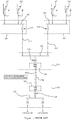
- the first converter platform 2 includes a first busbar 4 carrying a convenient ac voltage.
- the second converter platform 2' includes a second busbar 4' carrying a convenient ac voltage.
- Wind turbines 6 forming part of a wind farm or wind turbine park are connected together in strings by medium voltage (MV) or high voltage (HV) in-field ac cabling.
- a series of strings 8 1 ...8 m are connected to the first busbar 4 by circuit breakers 10.
- a series of strings 8' 1 ...8' m are connected to the second busbar 4' by circuit breakers 10. It will be readily appreciated that in each case m may be any convenient number and that each string may include any convenient number of wind turbines.
- a series of converter transformers 12 1 ...12 p are connected to the first busbar 4 by circuit breakers 14.
- Each converter transformer 12 includes a primary winding that is connected to the first busbar 4 and a series of secondary windings. Each secondary winding is connected to an AC/DC converter unit 16.
- a converter module 18 consists of a group of AC/DC converter units 16. More particularly, the first converter platform 2 includes a series of converter modules 18 1 ...18 p and each converter module includes a series of AC/DC converter units 16 1 ...16 r . It will be readily appreciated that in each case p and r may be any convenient number.
- Each AC/DC converter unit 16 has ac terminals that are connected to a secondary winding of the corresponding converter transformer 12.
- Each AC/DC converter unit 16 also has first and second dc terminals.
- the AC/DC converter units 16 are connected together in series on the dc-side as shown in Figures 2A and 3 to define first and second dc output terminals 20a and 20b for the first converter platform 2. More particularly, it can be seen that within the first converter module 18 1 the first dc terminal of the first AC/DC converter unit 16 1 defines the first dc output terminal 20a for the first converter platform 2, the second dc terminal of the first AC/DC converter unit 16 1 is connected to the first dc terminal of the second AC/DC converter unit 16 2 (i.e.
- the second dc terminal of the second AC/DC converter unit 16 2 is connected to the first dc terminal of the third AC/DC converter unit 16 3
- the second dc terminal of the third AC/DC converter unit 16 3 of the first converter module 18 1 is connected to the first dc terminal of the first AC/DC converter unit 16 1 of the second converter module 18 2 (i.e. the next converter module in the series).
- This interconnection sequence continues until the second dc terminal of the third AC/DC converter unit 16 3 of the fourth converter module 18 4 (i.e. the second dc terminal of the last AC/DC converter unit in the series of the last converter module in the series) which defines the second dc output terminal 20b for the first converter platform 2.
- the second converter platform 2' is configured in the same manner with converter transformer 12' 1 ...12' p , converter modules 18' 1 ...18' p , and AC/DC converter units 16' 1 ...16' r that define first and second dc output terminals 22a and 22b.
- the second dc output terminal 20b of the first converter platform 2 is connected to the first dc output terminal 22a of the second converter platform 2' by a dc connection line 24 implemented as HV dc cabling.
- the first dc output terminal 20a of the first converter platform 2 is connected to a first dc transmission line 26 and the second dc output terminal 22b of the second converter platform 2' is connected to a second dc transmission line 28.
- Both the first and second dc transmission lines can be implemented as HV dc cabling and carry a convenient dc transmission voltage.
- the first busbar 4 is connected to the second busbar 4' to form the electrical 'backbone' described above. More particularly, an ac connection line 30 implemented as MV or HV ac cabling that is adapted to carry a convenient ac interlinking voltage is connected to the first busbar 4 by means of a first connector transformer 32 and circuit breakers 34 and to the second busbar 4' by means of a second connector transformer 32' and circuit breakers 34.
- ac connection line 30 implemented as MV or HV ac cabling that is adapted to carry a convenient ac interlinking voltage is connected to the first busbar 4 by means of a first connector transformer 32 and circuit breakers 34 and to the second busbar 4' by means of a second connector transformer 32' and circuit breakers 34.
- the first and second converter platforms 4 and 4' are located offshore and can be separated by a distance of between 5 and 15 km, for example.
- the first and second dc transmission cables 26 and 28 are connected to an onshore converter station 36 shown in Figure 2B .
- the converter station 36 has first and second converter halls 38 and 38' that are each configured in a similar manner to the first and second converter platforms 4 and 4'. More particularly each converter hall 38 and 38' has a series of converter transformers 40 1 ...40 p or 40' 1 ...40' p connected to a common busbar 42 by circuit breakers 44.
- the common busbar 42 carries a convenient ac voltage.
- Each converter transformer 40 includes a secondary winding that is connected to the common busbar 42 and a series of primary windings. Each primary winding is connected to a DC/AC converter unit 46 or 46'.
- a converter module 48 or 48' consists of a group of DC/AC converter units 46 or 46'. More particularly, each converter hall 38 and 38' includes a series of converter modules 48 1 ...48 p or 48' 1 ...48' p and each converter module includes a series of DC/AC converter units 46 1 ...46 r or 46' 1 ...46' r .
- Each DC/AC converter unit 46 has ac terminals that are connected to a primary winding of the corresponding converter transformer 40.
- Each DC/AC converter unit 46 also has first and second dc terminals.
- the DC/AC converter units 46 are connected together in series on the dc-side as shown in Figure 2B to define first and second dc input terminals 50a and 50b for the first converter hall 38 and first and second dc input terminals 52a and 52b for the second converter hall 38'.
- the second dc input terminal 50b of the first converter hall 38 is connected to the first dc input terminal 52a of the second converter hall 38' by a ground connection 54.
- the first dc input terminal 50a of the first converter hall 38 is connected to the first dc transmission cable 26 and the second dc input terminal 52b of the second converter hall 38' is connected to the second dc transmission cable 28.
- First and second grid transformers 56 and 56' are connected to the common busbar 42 by circuit breakers 58.
- the grid transformers 56 and 56' provide power to a utility grid or power network at a convenient ac voltage.
- An auxiliary grid transformer 60 can also be connected to the common busbar by circuit breakers 62 to provide an auxiliary connection.
- Any particular converter module 18 or 18' can be isolated by means of the circuit breaker 14 that connects the associated converter transformer to the busbar.
- Power can also be transferred between the first and second busbars 4 and 4' through the ac connection line 30 to provide the advantages mentioned above.
- the power transmission system is similar to that shown in Figures 2A and 2B and like parts have been given the same reference numeral.
- the third converter platform 2" includes a third busbar 4" carrying a convenient ac voltage.
- Wind turbines 6 forming part of a wind farm are connected together in strings by medium voltage (MV) or high voltage (HV) in-field ac cabling.
- a series of strings 8" 1 ...8" m are connected to the third busbar 4" by circuit breakers 10.
- the third converter platform 2" is configured in the same manner as the first and second converter platforms 2 and 2' described above with converter transformer 12" 1 ...12" p , converter modules 18" 1 ...18" p , and AC/DC converter units 16" 1 ...16" r that define first and second dc output terminals 64a and 64b.
- the second dc output terminal 20b of the first converter platform 2 is connected to the first dc output terminal 22a of the second converter platform 2' by a first dc connection line 24 implemented as HV dc cabling.
- the second dc terminal 24b of the second converter platform 2' is connected to the first dc output terminal 64a of the third converter platform 2" by a second dc connection line 66 implemented as HV dc cabling.
- the first dc output terminal 20a of the first converter platform 2 is connected to the first dc transmission line 26 and the second dc output terminal 64b of the third converter platform 2" is connected to the second dc transmission line 28.
- Both the first and second dc transmission lines 26, 28 can be implemented as HV dc cabling and carry a convenient dc transmission voltage.
- the first busbar 4 is connected to the second and third busbars 4' and 4" to form the electrical 'backbone' described above. More particularly, an ac connection line 68 implemented as MV or HV ac cabling that is adapted to carry a convenient ac interlinking voltage is connected to the first busbar 4 by means of a first connector transformer 32 and circuit breakers 34, to the second busbar 4' by means of a second connector transformer 32' and circuit breakers 34, and to the third busbar 4" by means of a third connector transformer 32" and circuit breakers 34.
- ac connection line 68 implemented as MV or HV ac cabling that is adapted to carry a convenient ac interlinking voltage is connected to the first busbar 4 by means of a first connector transformer 32 and circuit breakers 34, to the second busbar 4' by means of a second connector transformer 32' and circuit breakers 34, and to the third busbar 4" by means of a third connector transformer 32" and circuit breakers 34.
- the first, second and third converter platforms 4, 4' and 4" are located offshore and adjacent converter platforms in the series can be separated by a distance of between 5 and 15 km, for example.
- the first and second dc transmission cables 26 and 28 are connected to an onshore converter station (not shown) but which can be configured in a similar way to the converter station 36 shown in Figure 2B .
- Other configurations of converter station are also possible for both of the arrangements of the power transmission system.
Landscapes
- Engineering & Computer Science (AREA)
- Power Engineering (AREA)
- Supply And Distribution Of Alternating Current (AREA)
- Inverter Devices (AREA)
- Rectifiers (AREA)
Claims (14)
- Système de transmission de puissance comprenant une série de deux plateformes de conversion en mer ou plus (2, 2') espacées l'une de l'autre et réparties dans une zone, chaque plateforme de conversion en mer (2, 2') comprenant : (i) une barre omnibus (4, 4') portant une tension alternative pour la plateforme de conversion en mer et pouvant être reliée à un ou plusieurs dispositifs (6), (ii) un ou plusieurs transformateurs de convertisseur (121...12p, 12'1...12p) reliés à la barre omnibus (4, 4'), et (iii) un module convertisseur seul ou une série de deux modules convertisseurs ou plus (181...18p, 18'1...18p), chaque module convertisseur ayant (a) des bornes à courant alternatif reliées à un transformateur de convertisseur respectif (121...12p, 12'1...12p), et (b) des première et deuxième bornes à courant continu ;
dans lequel pour la première plateforme de conversion en mer (2) de la série, la première borne à courant continu du module convertisseur seul ou du premier module convertisseur (181) de la série de deux modules convertisseurs ou plus (181...18p, 18'1...18p) est reliée à une première ligne de transmission continue (26) ;
dans lequel pour chaque plateforme de conversion en mer (2) autre que la dernière plateforme de conversion en mer de la série, la deuxième borne à courant continu du module convertisseur seul ou du dernier module convertisseur (18p) de la série de deux modules convertisseurs ou plus (181...18p, 18'1...18p) est reliée à la première borne à courant continu du module convertisseur seul ou du premier module convertisseur (181) de la série de deux modules convertisseurs ou plus (181...18p, 18'1...18p) de la plateforme de conversion en mer suivante de la série au moyen d'une ligne de connexion continue (24) ; et
dans lequel pour la dernière plateforme de conversion en mer (2') de la série, la deuxième borne à courant continu du module convertisseur seul ou du dernier module convertisseur (18p) de la série de deux modules convertisseurs ou plus (181...18p, 18'1...18p) est reliée à une deuxième ligne de transmission continue (28). - Système de transmission de puissance selon la revendication 1, dans lequel chaque plateforme de conversion en mer (2, 2') comprend deux transformateurs de convertisseur ou plus (121...12p, 12'1...12p) et une série de deux modules convertisseurs ou plus (181...18p, 18'1..18p).
- Système de transmission de puissance selon la revendication 2, dans lequel la deuxième borne à courant continu de chaque module convertisseur autre que le dernier module convertisseur (18p) de la série est reliée à la première borne à courant continu du module convertisseur suivant de la série.
- Système de transmission de puissance selon l'une quelconque des revendications précédentes, dans lequel chaque module convertisseur (181...18p, 18'1...18p) comprend un ou plusieurs convertisseurs alternatif-continu (161...16r), chaque convertisseur alternatif-continu ayant (a) des bornes à courant alternatif reliées au transformateur de convertisseur, et (b) des première et deuxième bornes à courant continu.
- Système de transmission de puissance selon la revendication 4, dans lequel chaque module convertisseur (181...18p, 18'1...18p) comprend une série de deux convertisseurs alternatif-continu ou plus (161...16r) et dans lequel pour chaque module convertisseur, la première borne à courant continu du premier convertisseur alternatif-continu (161) de la série définit la première borne à courant continu du module convertisseur, la deuxième borne à courant continu du dernier convertisseur alternatif-continu (16r) de la série définit la deuxième borne à courant continu du module convertisseur, et la deuxième borne à courant continu de chaque convertisseur alternatif-continu autre que le dernier convertisseur alternatif-continu de la série est reliée à la première borne à courant continu du convertisseur alternatif-continu suivant de la série.
- Système de transmission de puissance selon l'une quelconque des revendications précédentes, comprenant en outre une station de conversion (36) et dans lequel les première et deuxième lignes de transmission continue (26, 28) sont reliées à la station de conversion (36).
- Système de transmission de puissance selon la revendication 6, dans lequel la station de conversion est une station de conversion en mer (36).
- Système de transmission de puissance selon l'une quelconque des revendications précédentes, dans lequel les barres omnibus (4, 4' ; 4, 4', 4") sont reliées entre elles par une ligne de connexion à courant alternatif (30 ; 68).
- Système de transmission de puissance selon la revendication 8, comprenant une série de trois plateformes de conversion en mer ou plus (2, 2', 2") et dans lequel la ligne de connexion à courant alternatif (68) relie les barres omnibus (4, 4', 4") entre elles en parallèle.
- Système de transmission de puissance selon la revendication 8 ou 9, dans lequel la ligne de connexion à courant alternatif (30 ; 68) est reliée à chaque barre omnibus (4, 4' ; 4, 4', 4") par un transformateur de connexion (32, 32' ; 32, 32', 32").
- Système de transmission de puissance selon l'une quelconque des revendications précédentes, dans lequel chaque transformateur de convertisseur (32, 32') est relié à la barre omnibus (4, 4') au moyen d'un interrupteur ou d'un disjoncteur (34).
- Système de transmission de puissance selon l'une quelconque des revendications précédentes, dans lequel chaque transformateur de convertisseur (121...12p, 12'1...12p) est relié à la barre omnibus (4, 4') au moyen d'un interrupteur ou d'un disjoncteur (14).
- Parc éolien comprenant un système de transmission de puissance selon l'une quelconque des revendications précédentes et une pluralité d'éoliennes, dans lequel les plateformes de conversion en mer sont réparties dans le parc éolien et chaque éolienne est reliée à la barre omnibus (4, 4') d'une plateforme de conversion en mer (2, 2').
- Procédé de mise en oeuvre d'un système de transmission de puissance selon l'une quelconque des revendications 8 à 10, le procédé étant caractérisé par l'étape consistant à transférer de l'énergie via la ligne de connexion à courant alternatif (30).
Priority Applications (6)
| Application Number | Priority Date | Filing Date | Title |
|---|---|---|---|
| EP12186514.1A EP2713468B1 (fr) | 2012-09-28 | 2012-09-28 | Systèmes électriques de transmission de puissance |
| DK12186514T DK2713468T3 (da) | 2012-09-28 | 2012-09-28 | Elektriske energioverførselssystemer |
| CA2827666A CA2827666A1 (fr) | 2012-09-28 | 2013-09-19 | Mecanismes de transmission d'energie |
| BRBR102013024576-3A BR102013024576A2 (pt) | 2012-09-28 | 2013-09-25 | Sistema de transmissão de potência, parque eólico e método para operar um sistema de transmissão de potência |
| CN201310447717.6A CN103715708A (zh) | 2012-09-28 | 2013-09-27 | 输电系统 |
| US14/038,983 US9197069B2 (en) | 2012-09-28 | 2013-09-27 | Power transmission systems |
Applications Claiming Priority (1)
| Application Number | Priority Date | Filing Date | Title |
|---|---|---|---|
| EP12186514.1A EP2713468B1 (fr) | 2012-09-28 | 2012-09-28 | Systèmes électriques de transmission de puissance |
Publications (2)
| Publication Number | Publication Date |
|---|---|
| EP2713468A1 EP2713468A1 (fr) | 2014-04-02 |
| EP2713468B1 true EP2713468B1 (fr) | 2019-08-07 |
Family
ID=47296911
Family Applications (1)
| Application Number | Title | Priority Date | Filing Date |
|---|---|---|---|
| EP12186514.1A Active EP2713468B1 (fr) | 2012-09-28 | 2012-09-28 | Systèmes électriques de transmission de puissance |
Country Status (6)
| Country | Link |
|---|---|
| US (1) | US9197069B2 (fr) |
| EP (1) | EP2713468B1 (fr) |
| CN (1) | CN103715708A (fr) |
| BR (1) | BR102013024576A2 (fr) |
| CA (1) | CA2827666A1 (fr) |
| DK (1) | DK2713468T3 (fr) |
Families Citing this family (24)
| Publication number | Priority date | Publication date | Assignee | Title |
|---|---|---|---|---|
| EP1908163A1 (fr) * | 2005-07-01 | 2008-04-09 | Vestas Wind Systems A/S | Turbine eolienne a vitesse de rotor variable, centrale eolienne, procede de transmission d energie electrique et procede d entretien ou d inspection d une turbine eolienne a vitesse de rotor variable |
| US10424935B2 (en) | 2009-09-15 | 2019-09-24 | Rajiv Kumar Varma | Multivariable modulator controller for power generation facility |
| EP2911260A1 (fr) * | 2014-02-19 | 2015-08-26 | Siemens Aktiengesellschaft | Dispositif d'injection d'énergie électrique éolienne dans un réseau électrique |
| CN105990846B (zh) * | 2014-09-05 | 2018-10-09 | 台达电子工业股份有限公司 | 风电变流器装置和变流器装置 |
| US9768706B2 (en) | 2014-09-05 | 2017-09-19 | Delta Electronics, Inc. | Wind power converter device and converter device |
| EP3086432B1 (fr) * | 2015-04-23 | 2018-07-18 | GE Energy Power Conversion Technology Ltd | Systèmes de distribution de puissance |
| EP3116089B1 (fr) * | 2015-07-07 | 2020-02-26 | Siemens Gamesa Renewable Energy A/S | Fonctionnement d'une turbine à vent, sur la base d'une fréquence d'un signal de tension de sortie de courant alternatif fourni par un convertisseur de puissance d'une éolienne |
| US9945359B2 (en) * | 2015-08-13 | 2018-04-17 | Abb Schweiz Ag | DC output wind turbine with power dissipation |
| US10615608B2 (en) | 2017-04-07 | 2020-04-07 | General Electric Company | Low-wind operation of clustered doubly fed induction generator wind turbines |
| US10396695B2 (en) * | 2017-04-18 | 2019-08-27 | General Electric Company | Method for protecting an electrical power system |
| WO2018218040A1 (fr) | 2017-05-24 | 2018-11-29 | J. Ray Mcdermott, S.A. | Conception de plateforme modulaire hvdc |
| EP3656033B1 (fr) | 2017-08-30 | 2022-07-27 | Siemens Energy Global GmbH & Co. KG | Ensemble de convertisseurs d'énergie pour raccorder des éoliennes à un réseau d'alimentation électrique |
| CN109698514B (zh) * | 2017-10-24 | 2022-07-22 | 南京南瑞继保电气有限公司 | 一种换流器控制方法及装置 |
| US10819103B2 (en) * | 2017-12-07 | 2020-10-27 | General Electric Company | Systems and methods for isolating faults in electrical power systems connected to a power grid |
| EP3512062A1 (fr) * | 2018-01-11 | 2019-07-17 | Ørsted Wind Power A/S | Parc éolien et sous-station en mer |
| US11031773B2 (en) | 2019-03-27 | 2021-06-08 | Abb Power Grids Switzerland Ag | Transformer isolation response using direct current link |
| EP3751692B1 (fr) * | 2019-06-11 | 2023-09-20 | Siemens Energy Global GmbH & Co. KG | Station de transmission de courant continu à haute tension |
| CN110829479A (zh) * | 2019-10-30 | 2020-02-21 | 浙江大学 | 一种海上风电场高频不控整流直流输电系统 |
| EP3826102A1 (fr) * | 2019-11-20 | 2021-05-26 | Vestas Wind Systems A/S | Surveillance de système de batterie basée sur un modèle |
| EP3913762A1 (fr) * | 2020-05-22 | 2021-11-24 | General Electric Technology GmbH | Système de transmission de puissance bipolaire hvdc configurable pour un fonctionnement monopolaire |
| EP4184739A1 (fr) * | 2021-11-18 | 2023-05-24 | General Electric Technology GmbH | Améliorations apportées ou se rapportant à des schémas de transmission de puissance bipolaire |
| NO347131B1 (en) | 2021-03-17 | 2023-05-30 | Aker Solutions As | A high voltage offshore power plant power distribution assembly, a high voltage subsea transformer, and a appurtenant installation method |
| CN113206515B (zh) * | 2021-04-28 | 2023-08-22 | 中国能源建设集团广东省电力设计研究院有限公司 | 一种海上风电场500kV送出系统 |
| CN113206514B (zh) * | 2021-04-28 | 2023-06-16 | 中国能源建设集团广东省电力设计研究院有限公司 | 一种海上风电66kV集电系统及输电系统 |
Family Cites Families (11)
| Publication number | Priority date | Publication date | Assignee | Title |
|---|---|---|---|---|
| SE504522C2 (sv) * | 1995-07-06 | 1997-02-24 | Asea Brown Boveri | Kraftöverföring med högspänd likström innefattande fler än två strömriktarstationer |
| JPH09312934A (ja) * | 1996-05-21 | 1997-12-02 | Hitachi Ltd | 電力系統システムの電力系統安定化装置 |
| SE518121C2 (sv) * | 1999-12-23 | 2002-08-27 | Abb Ab | Elkraftsystem baserat på förnyelsebara energikällor |
| US8345457B2 (en) * | 2007-09-05 | 2013-01-01 | Abb Technology Ag | Voltage source converter for high voltage direct current power transmission |
| WO2009110648A1 (fr) * | 2008-03-06 | 2009-09-11 | Jun Sung Electronics Co., Ltd | Convertisseur pour ccht |
| DE102008022618A1 (de) * | 2008-05-07 | 2009-12-31 | Siemens Aktiengesellschaft | Stromversorgungseinrichtung |
| US8212408B2 (en) * | 2008-12-24 | 2012-07-03 | Alencon Acquisition Co., Llc. | Collection of electric power from renewable energy sources via high voltage, direct current systems with conversion and supply to an alternating current transmission network |
| US20120175962A1 (en) * | 2011-01-11 | 2012-07-12 | Converteam Technology Ltd. | Power Collection and Transmission Systems |
| CN102427243B (zh) * | 2011-10-28 | 2014-05-07 | 华中科技大学 | 一种将风电场和常规电厂联合并网的多端直流输电系统 |
| US20130193766A1 (en) * | 2012-01-31 | 2013-08-01 | Atlantic Grid Operations A., Llc | Control and protection of a dc power grid |
| US9048694B2 (en) * | 2012-02-01 | 2015-06-02 | Abb Research Ltd | DC connection scheme for windfarm with internal MVDC collection grid |
-
2012
- 2012-09-28 DK DK12186514T patent/DK2713468T3/da active
- 2012-09-28 EP EP12186514.1A patent/EP2713468B1/fr active Active
-
2013
- 2013-09-19 CA CA2827666A patent/CA2827666A1/fr not_active Abandoned
- 2013-09-25 BR BRBR102013024576-3A patent/BR102013024576A2/pt not_active Application Discontinuation
- 2013-09-27 US US14/038,983 patent/US9197069B2/en active Active
- 2013-09-27 CN CN201310447717.6A patent/CN103715708A/zh active Pending
Non-Patent Citations (2)
| Title |
|---|
| DRIVERS ET AL: " ABB Group Slide 1 PowDoc id Developments in Multiterminal HVDC", ABB POWER SYSTEMS - HVDC, 4 October 2011 (2011-10-04), XP055460653, Retrieved from the Internet <URL:http://www.ieee.ca/epec11/admin/04-0800-hvdc_plenary_jacobson.pdf> * |
| MICHAEL P BAHRMAN ET AL: "The ABCs of HVDC transmission technologies", IEEE POWER AND ENERGY MAGAZINE, IEEE., PISCATAWAY, NJ, US, vol. 4, no. 2, 1 March 2007 (2007-03-01), pages 32 - 44, XP011174684, ISSN: 1540-7977 * |
Also Published As
| Publication number | Publication date |
|---|---|
| DK2713468T3 (da) | 2019-11-04 |
| CN103715708A (zh) | 2014-04-09 |
| EP2713468A1 (fr) | 2014-04-02 |
| US20140092650A1 (en) | 2014-04-03 |
| US9197069B2 (en) | 2015-11-24 |
| BR102013024576A2 (pt) | 2014-10-29 |
| CA2827666A1 (fr) | 2014-03-28 |
Similar Documents
| Publication | Publication Date | Title |
|---|---|---|
| EP2713468B1 (fr) | Systèmes électriques de transmission de puissance | |
| Saeedifard et al. | DC power systems: Challenges and opportunities | |
| EP2341594A1 (fr) | Systèmes de transmission et de collecte d'alimentation | |
| US20120175962A1 (en) | Power Collection and Transmission Systems | |
| EP2033292B1 (fr) | Convertisseur ccht modulaire | |
| Kirby et al. | HVDC transmission for large offshore windfarms | |
| EP2810353B1 (fr) | Schéma de connexion en courant continu pour parc éolien avec grille de captage interne à courant continu et moyenne tension | |
| EP2478608B1 (fr) | Système de collecte et de distribution d'énergie | |
| US9800054B2 (en) | DC connection system for renewable power generators | |
| EP2904682B1 (fr) | Système de collecte à courant continu (cc) moyenne tension avec électronique de puissance | |
| US11228178B2 (en) | Photovoltaic power plant system | |
| US20200370537A1 (en) | An offshore wind farm and substation | |
| US10505467B2 (en) | Converter station with diode rectifier | |
| Abeynayake et al. | A review on MVdc collection systems for high-power offshore wind farms | |
| Srikakulapu et al. | Electrical collector topologies for offshore wind power plants: A survey | |
| KR20120095248A (ko) | 집전 및 송전 시스템 | |
| CN102623986A (zh) | 电力采集和传输系统 | |
| US20240052806A1 (en) | A high voltage offshore power plant power distribution assembly | |
| US20230246450A1 (en) | Wind power plant collector system | |
| Völzke et al. | Integration of large-scale windfarms into the German grid | |
| Ghomri et al. | HVDC LIGHT: A Solution for Algerian–Spanish Power System Interconnection | |
| Smith | DC architectures for renewables energy and future grids | |
| BARTHOLD et al. | iMod Inc1, Electranix Corporation2, University of Manitoba3 USA Canada Canada |
Legal Events
| Date | Code | Title | Description |
|---|---|---|---|
| PUAI | Public reference made under article 153(3) epc to a published international application that has entered the european phase |
Free format text: ORIGINAL CODE: 0009012 |
|
| AK | Designated contracting states |
Kind code of ref document: A1 Designated state(s): AL AT BE BG CH CY CZ DE DK EE ES FI FR GB GR HR HU IE IS IT LI LT LU LV MC MK MT NL NO PL PT RO RS SE SI SK SM TR |
|
| AX | Request for extension of the european patent |
Extension state: BA ME |
|
| 17P | Request for examination filed |
Effective date: 20140916 |
|
| RBV | Designated contracting states (corrected) |
Designated state(s): AL AT BE BG CH CY CZ DE DK EE ES FI FR GB GR HR HU IE IS IT LI LT LU LV MC MK MT NL NO PL PT RO RS SE SI SK SM TR |
|
| STAA | Information on the status of an ep patent application or granted ep patent |
Free format text: STATUS: EXAMINATION IS IN PROGRESS |
|
| 17Q | First examination report despatched |
Effective date: 20161220 |
|
| GRAP | Despatch of communication of intention to grant a patent |
Free format text: ORIGINAL CODE: EPIDOSNIGR1 |
|
| STAA | Information on the status of an ep patent application or granted ep patent |
Free format text: STATUS: GRANT OF PATENT IS INTENDED |
|
| RIC1 | Information provided on ipc code assigned before grant |
Ipc: H02M 1/00 20060101ALN20190125BHEP Ipc: H02J 3/38 20060101ALI20190125BHEP Ipc: H02J 3/36 20060101AFI20190125BHEP Ipc: H02M 7/02 20060101ALI20190125BHEP Ipc: H02M 7/757 20060101ALI20190125BHEP |
|
| INTG | Intention to grant announced |
Effective date: 20190301 |
|
| GRAS | Grant fee paid |
Free format text: ORIGINAL CODE: EPIDOSNIGR3 |
|
| GRAA | (expected) grant |
Free format text: ORIGINAL CODE: 0009210 |
|
| STAA | Information on the status of an ep patent application or granted ep patent |
Free format text: STATUS: THE PATENT HAS BEEN GRANTED |
|
| AK | Designated contracting states |
Kind code of ref document: B1 Designated state(s): AL AT BE BG CH CY CZ DE DK EE ES FI FR GB GR HR HU IE IS IT LI LT LU LV MC MK MT NL NO PL PT RO RS SE SI SK SM TR |
|
| REG | Reference to a national code |
Ref country code: GB Ref legal event code: FG4D |
|
| REG | Reference to a national code |
Ref country code: CH Ref legal event code: EP Ref country code: AT Ref legal event code: REF Ref document number: 1165295 Country of ref document: AT Kind code of ref document: T Effective date: 20190815 |
|
| REG | Reference to a national code |
Ref country code: DE Ref legal event code: R096 Ref document number: 602012062631 Country of ref document: DE |
|
| REG | Reference to a national code |
Ref country code: IE Ref legal event code: FG4D |
|
| REG | Reference to a national code |
Ref country code: DK Ref legal event code: T3 Effective date: 20191101 |
|
| REG | Reference to a national code |
Ref country code: NL Ref legal event code: MP Effective date: 20190807 |
|
| REG | Reference to a national code |
Ref country code: LT Ref legal event code: MG4D |
|
| PG25 | Lapsed in a contracting state [announced via postgrant information from national office to epo] |
Ref country code: NL Free format text: LAPSE BECAUSE OF FAILURE TO SUBMIT A TRANSLATION OF THE DESCRIPTION OR TO PAY THE FEE WITHIN THE PRESCRIBED TIME-LIMIT Effective date: 20190807 Ref country code: SE Free format text: LAPSE BECAUSE OF FAILURE TO SUBMIT A TRANSLATION OF THE DESCRIPTION OR TO PAY THE FEE WITHIN THE PRESCRIBED TIME-LIMIT Effective date: 20190807 Ref country code: BG Free format text: LAPSE BECAUSE OF FAILURE TO SUBMIT A TRANSLATION OF THE DESCRIPTION OR TO PAY THE FEE WITHIN THE PRESCRIBED TIME-LIMIT Effective date: 20191107 Ref country code: HR Free format text: LAPSE BECAUSE OF FAILURE TO SUBMIT A TRANSLATION OF THE DESCRIPTION OR TO PAY THE FEE WITHIN THE PRESCRIBED TIME-LIMIT Effective date: 20190807 Ref country code: NO Free format text: LAPSE BECAUSE OF FAILURE TO SUBMIT A TRANSLATION OF THE DESCRIPTION OR TO PAY THE FEE WITHIN THE PRESCRIBED TIME-LIMIT Effective date: 20191107 Ref country code: LT Free format text: LAPSE BECAUSE OF FAILURE TO SUBMIT A TRANSLATION OF THE DESCRIPTION OR TO PAY THE FEE WITHIN THE PRESCRIBED TIME-LIMIT Effective date: 20190807 Ref country code: PT Free format text: LAPSE BECAUSE OF FAILURE TO SUBMIT A TRANSLATION OF THE DESCRIPTION OR TO PAY THE FEE WITHIN THE PRESCRIBED TIME-LIMIT Effective date: 20191209 Ref country code: FI Free format text: LAPSE BECAUSE OF FAILURE TO SUBMIT A TRANSLATION OF THE DESCRIPTION OR TO PAY THE FEE WITHIN THE PRESCRIBED TIME-LIMIT Effective date: 20190807 |
|
| REG | Reference to a national code |
Ref country code: AT Ref legal event code: MK05 Ref document number: 1165295 Country of ref document: AT Kind code of ref document: T Effective date: 20190807 |
|
| PG25 | Lapsed in a contracting state [announced via postgrant information from national office to epo] |
Ref country code: LV Free format text: LAPSE BECAUSE OF FAILURE TO SUBMIT A TRANSLATION OF THE DESCRIPTION OR TO PAY THE FEE WITHIN THE PRESCRIBED TIME-LIMIT Effective date: 20190807 Ref country code: GR Free format text: LAPSE BECAUSE OF FAILURE TO SUBMIT A TRANSLATION OF THE DESCRIPTION OR TO PAY THE FEE WITHIN THE PRESCRIBED TIME-LIMIT Effective date: 20191108 Ref country code: AL Free format text: LAPSE BECAUSE OF FAILURE TO SUBMIT A TRANSLATION OF THE DESCRIPTION OR TO PAY THE FEE WITHIN THE PRESCRIBED TIME-LIMIT Effective date: 20190807 Ref country code: IS Free format text: LAPSE BECAUSE OF FAILURE TO SUBMIT A TRANSLATION OF THE DESCRIPTION OR TO PAY THE FEE WITHIN THE PRESCRIBED TIME-LIMIT Effective date: 20191207 Ref country code: RS Free format text: LAPSE BECAUSE OF FAILURE TO SUBMIT A TRANSLATION OF THE DESCRIPTION OR TO PAY THE FEE WITHIN THE PRESCRIBED TIME-LIMIT Effective date: 20190807 Ref country code: ES Free format text: LAPSE BECAUSE OF FAILURE TO SUBMIT A TRANSLATION OF THE DESCRIPTION OR TO PAY THE FEE WITHIN THE PRESCRIBED TIME-LIMIT Effective date: 20190807 |
|
| PG25 | Lapsed in a contracting state [announced via postgrant information from national office to epo] |
Ref country code: TR Free format text: LAPSE BECAUSE OF FAILURE TO SUBMIT A TRANSLATION OF THE DESCRIPTION OR TO PAY THE FEE WITHIN THE PRESCRIBED TIME-LIMIT Effective date: 20190807 |
|
| PG25 | Lapsed in a contracting state [announced via postgrant information from national office to epo] |
Ref country code: AT Free format text: LAPSE BECAUSE OF FAILURE TO SUBMIT A TRANSLATION OF THE DESCRIPTION OR TO PAY THE FEE WITHIN THE PRESCRIBED TIME-LIMIT Effective date: 20190807 Ref country code: RO Free format text: LAPSE BECAUSE OF FAILURE TO SUBMIT A TRANSLATION OF THE DESCRIPTION OR TO PAY THE FEE WITHIN THE PRESCRIBED TIME-LIMIT Effective date: 20190807 Ref country code: IT Free format text: LAPSE BECAUSE OF FAILURE TO SUBMIT A TRANSLATION OF THE DESCRIPTION OR TO PAY THE FEE WITHIN THE PRESCRIBED TIME-LIMIT Effective date: 20190807 Ref country code: EE Free format text: LAPSE BECAUSE OF FAILURE TO SUBMIT A TRANSLATION OF THE DESCRIPTION OR TO PAY THE FEE WITHIN THE PRESCRIBED TIME-LIMIT Effective date: 20190807 Ref country code: PL Free format text: LAPSE BECAUSE OF FAILURE TO SUBMIT A TRANSLATION OF THE DESCRIPTION OR TO PAY THE FEE WITHIN THE PRESCRIBED TIME-LIMIT Effective date: 20190807 |
|
| PG25 | Lapsed in a contracting state [announced via postgrant information from national office to epo] |
Ref country code: MC Free format text: LAPSE BECAUSE OF FAILURE TO SUBMIT A TRANSLATION OF THE DESCRIPTION OR TO PAY THE FEE WITHIN THE PRESCRIBED TIME-LIMIT Effective date: 20190807 Ref country code: SK Free format text: LAPSE BECAUSE OF FAILURE TO SUBMIT A TRANSLATION OF THE DESCRIPTION OR TO PAY THE FEE WITHIN THE PRESCRIBED TIME-LIMIT Effective date: 20190807 Ref country code: CZ Free format text: LAPSE BECAUSE OF FAILURE TO SUBMIT A TRANSLATION OF THE DESCRIPTION OR TO PAY THE FEE WITHIN THE PRESCRIBED TIME-LIMIT Effective date: 20190807 Ref country code: IS Free format text: LAPSE BECAUSE OF FAILURE TO SUBMIT A TRANSLATION OF THE DESCRIPTION OR TO PAY THE FEE WITHIN THE PRESCRIBED TIME-LIMIT Effective date: 20200224 Ref country code: SM Free format text: LAPSE BECAUSE OF FAILURE TO SUBMIT A TRANSLATION OF THE DESCRIPTION OR TO PAY THE FEE WITHIN THE PRESCRIBED TIME-LIMIT Effective date: 20190807 |
|
| REG | Reference to a national code |
Ref country code: CH Ref legal event code: PL |
|
| REG | Reference to a national code |
Ref country code: DE Ref legal event code: R097 Ref document number: 602012062631 Country of ref document: DE |
|
| PLBE | No opposition filed within time limit |
Free format text: ORIGINAL CODE: 0009261 |
|
| STAA | Information on the status of an ep patent application or granted ep patent |
Free format text: STATUS: NO OPPOSITION FILED WITHIN TIME LIMIT |
|
| PG2D | Information on lapse in contracting state deleted |
Ref country code: IS |
|
| PG25 | Lapsed in a contracting state [announced via postgrant information from national office to epo] |
Ref country code: LI Free format text: LAPSE BECAUSE OF NON-PAYMENT OF DUE FEES Effective date: 20190930 Ref country code: LU Free format text: LAPSE BECAUSE OF NON-PAYMENT OF DUE FEES Effective date: 20190928 Ref country code: IE Free format text: LAPSE BECAUSE OF NON-PAYMENT OF DUE FEES Effective date: 20190928 Ref country code: CH Free format text: LAPSE BECAUSE OF NON-PAYMENT OF DUE FEES Effective date: 20190930 |
|
| 26N | No opposition filed |
Effective date: 20200603 |
|
| REG | Reference to a national code |
Ref country code: BE Ref legal event code: MM Effective date: 20190930 |
|
| PG25 | Lapsed in a contracting state [announced via postgrant information from national office to epo] |
Ref country code: SI Free format text: LAPSE BECAUSE OF FAILURE TO SUBMIT A TRANSLATION OF THE DESCRIPTION OR TO PAY THE FEE WITHIN THE PRESCRIBED TIME-LIMIT Effective date: 20190807 Ref country code: BE Free format text: LAPSE BECAUSE OF NON-PAYMENT OF DUE FEES Effective date: 20190930 |
|
| PG25 | Lapsed in a contracting state [announced via postgrant information from national office to epo] |
Ref country code: CY Free format text: LAPSE BECAUSE OF FAILURE TO SUBMIT A TRANSLATION OF THE DESCRIPTION OR TO PAY THE FEE WITHIN THE PRESCRIBED TIME-LIMIT Effective date: 20190807 |
|
| PG25 | Lapsed in a contracting state [announced via postgrant information from national office to epo] |
Ref country code: HU Free format text: LAPSE BECAUSE OF FAILURE TO SUBMIT A TRANSLATION OF THE DESCRIPTION OR TO PAY THE FEE WITHIN THE PRESCRIBED TIME-LIMIT; INVALID AB INITIO Effective date: 20120928 Ref country code: MT Free format text: LAPSE BECAUSE OF FAILURE TO SUBMIT A TRANSLATION OF THE DESCRIPTION OR TO PAY THE FEE WITHIN THE PRESCRIBED TIME-LIMIT Effective date: 20190807 |
|
| PG25 | Lapsed in a contracting state [announced via postgrant information from national office to epo] |
Ref country code: MK Free format text: LAPSE BECAUSE OF FAILURE TO SUBMIT A TRANSLATION OF THE DESCRIPTION OR TO PAY THE FEE WITHIN THE PRESCRIBED TIME-LIMIT Effective date: 20190807 |
|
| PGFP | Annual fee paid to national office [announced via postgrant information from national office to epo] |
Ref country code: GB Payment date: 20230823 Year of fee payment: 12 |
|
| PGFP | Annual fee paid to national office [announced via postgrant information from national office to epo] |
Ref country code: FR Payment date: 20230822 Year of fee payment: 12 Ref country code: DK Payment date: 20230822 Year of fee payment: 12 Ref country code: DE Payment date: 20230822 Year of fee payment: 12 |