EP2713156B1 - Device and method for ray scanning and imaging - Google Patents
Device and method for ray scanning and imaging Download PDFInfo
- Publication number
- EP2713156B1 EP2713156B1 EP12870875.7A EP12870875A EP2713156B1 EP 2713156 B1 EP2713156 B1 EP 2713156B1 EP 12870875 A EP12870875 A EP 12870875A EP 2713156 B1 EP2713156 B1 EP 2713156B1
- Authority
- EP
- European Patent Office
- Prior art keywords
- ray
- detectors
- linear arrays
- generators
- inspected
- Prior art date
- Legal status (The legal status is an assumption and is not a legal conclusion. Google has not performed a legal analysis and makes no representation as to the accuracy of the status listed.)
- Active
Links
Images



Classifications
-
- G—PHYSICS
- G01—MEASURING; TESTING
- G01V—GEOPHYSICS; GRAVITATIONAL MEASUREMENTS; DETECTING MASSES OR OBJECTS; TAGS
- G01V5/00—Prospecting or detecting by the use of ionising radiation, e.g. of natural or induced radioactivity
- G01V5/20—Detecting prohibited goods, e.g. weapons, explosives, hazardous substances, contraband or smuggled objects
- G01V5/22—Active interrogation, i.e. by irradiating objects or goods using external radiation sources, e.g. using gamma rays or cosmic rays
-
- A—HUMAN NECESSITIES
- A61—MEDICAL OR VETERINARY SCIENCE; HYGIENE
- A61B—DIAGNOSIS; SURGERY; IDENTIFICATION
- A61B6/00—Apparatus or devices for radiation diagnosis; Apparatus or devices for radiation diagnosis combined with radiation therapy equipment
- A61B6/02—Arrangements for diagnosis sequentially in different planes; Stereoscopic radiation diagnosis
- A61B6/03—Computed tomography [CT]
- A61B6/032—Transmission computed tomography [CT]
-
- A—HUMAN NECESSITIES
- A61—MEDICAL OR VETERINARY SCIENCE; HYGIENE
- A61B—DIAGNOSIS; SURGERY; IDENTIFICATION
- A61B6/00—Apparatus or devices for radiation diagnosis; Apparatus or devices for radiation diagnosis combined with radiation therapy equipment
- A61B6/40—Arrangements for generating radiation specially adapted for radiation diagnosis
- A61B6/4007—Arrangements for generating radiation specially adapted for radiation diagnosis characterised by using a plurality of source units
-
- A—HUMAN NECESSITIES
- A61—MEDICAL OR VETERINARY SCIENCE; HYGIENE
- A61B—DIAGNOSIS; SURGERY; IDENTIFICATION
- A61B6/00—Apparatus or devices for radiation diagnosis; Apparatus or devices for radiation diagnosis combined with radiation therapy equipment
- A61B6/40—Arrangements for generating radiation specially adapted for radiation diagnosis
- A61B6/4007—Arrangements for generating radiation specially adapted for radiation diagnosis characterised by using a plurality of source units
- A61B6/4014—Arrangements for generating radiation specially adapted for radiation diagnosis characterised by using a plurality of source units arranged in multiple source-detector units
-
- A—HUMAN NECESSITIES
- A61—MEDICAL OR VETERINARY SCIENCE; HYGIENE
- A61B—DIAGNOSIS; SURGERY; IDENTIFICATION
- A61B6/00—Apparatus or devices for radiation diagnosis; Apparatus or devices for radiation diagnosis combined with radiation therapy equipment
- A61B6/40—Arrangements for generating radiation specially adapted for radiation diagnosis
- A61B6/4064—Arrangements for generating radiation specially adapted for radiation diagnosis specially adapted for producing a particular type of beam
- A61B6/4078—Fan-beams
-
- A—HUMAN NECESSITIES
- A61—MEDICAL OR VETERINARY SCIENCE; HYGIENE
- A61B—DIAGNOSIS; SURGERY; IDENTIFICATION
- A61B6/00—Apparatus or devices for radiation diagnosis; Apparatus or devices for radiation diagnosis combined with radiation therapy equipment
- A61B6/42—Arrangements for detecting radiation specially adapted for radiation diagnosis
- A61B6/4208—Arrangements for detecting radiation specially adapted for radiation diagnosis characterised by using a particular type of detector
- A61B6/4233—Arrangements for detecting radiation specially adapted for radiation diagnosis characterised by using a particular type of detector using matrix detectors
-
- A—HUMAN NECESSITIES
- A61—MEDICAL OR VETERINARY SCIENCE; HYGIENE
- A61B—DIAGNOSIS; SURGERY; IDENTIFICATION
- A61B6/00—Apparatus or devices for radiation diagnosis; Apparatus or devices for radiation diagnosis combined with radiation therapy equipment
- A61B6/42—Arrangements for detecting radiation specially adapted for radiation diagnosis
- A61B6/4275—Arrangements for detecting radiation specially adapted for radiation diagnosis using a detector unit almost surrounding the patient, e.g. more than 180°
-
- G—PHYSICS
- G01—MEASURING; TESTING
- G01N—INVESTIGATING OR ANALYSING MATERIALS BY DETERMINING THEIR CHEMICAL OR PHYSICAL PROPERTIES
- G01N23/00—Investigating or analysing materials by the use of wave or particle radiation, e.g. X-rays or neutrons, not covered by groups G01N3/00 – G01N17/00, G01N21/00 or G01N22/00
- G01N23/02—Investigating or analysing materials by the use of wave or particle radiation, e.g. X-rays or neutrons, not covered by groups G01N3/00 – G01N17/00, G01N21/00 or G01N22/00 by transmitting the radiation through the material
- G01N23/04—Investigating or analysing materials by the use of wave or particle radiation, e.g. X-rays or neutrons, not covered by groups G01N3/00 – G01N17/00, G01N21/00 or G01N22/00 by transmitting the radiation through the material and forming images of the material
- G01N23/046—Investigating or analysing materials by the use of wave or particle radiation, e.g. X-rays or neutrons, not covered by groups G01N3/00 – G01N17/00, G01N21/00 or G01N22/00 by transmitting the radiation through the material and forming images of the material using tomography, e.g. computed tomography [CT]
-
- G—PHYSICS
- G01—MEASURING; TESTING
- G01T—MEASUREMENT OF NUCLEAR OR X-RADIATION
- G01T1/00—Measuring X-radiation, gamma radiation, corpuscular radiation, or cosmic radiation
- G01T1/29—Measurement performed on radiation beams, e.g. position or section of the beam; Measurement of spatial distribution of radiation
- G01T1/2914—Measurement of spatial distribution of radiation
- G01T1/2985—In depth localisation, e.g. using positron emitters; Tomographic imaging (longitudinal and transverse section imaging; apparatus for radiation diagnosis sequentially in different planes, steroscopic radiation diagnosis)
-
- G—PHYSICS
- G01—MEASURING; TESTING
- G01V—GEOPHYSICS; GRAVITATIONAL MEASUREMENTS; DETECTING MASSES OR OBJECTS; TAGS
- G01V5/00—Prospecting or detecting by the use of ionising radiation, e.g. of natural or induced radioactivity
- G01V5/20—Detecting prohibited goods, e.g. weapons, explosives, hazardous substances, contraband or smuggled objects
- G01V5/22—Active interrogation, i.e. by irradiating objects or goods using external radiation sources, e.g. using gamma rays or cosmic rays
- G01V5/226—Active interrogation, i.e. by irradiating objects or goods using external radiation sources, e.g. using gamma rays or cosmic rays using tomography
Definitions
- the present invention relates to a radiation imaging field, and in particular, to apparatus and method for ray scanning imaging.
- Radiation imaging apparatus is generally made in accordance with principles of exponential ray attenuation. That is, scanning of the object to be inspected is carried out by the ray beams emitted from the radiation source. The ray beams pass through the object to be inspected, and are received by the ray collection device. Three-dimensional images are composed or reconstructed and displayed based on ray detection values received by the ray collection device.
- Fig. 1 shows a structural diagram of a prior art radiation imaging apparatus.
- the radiation imaging apparatus comprises a gantry 13, a ray source 11 connected to the gantry 13, a detection arrangement 12 placed, opposite to the ray source 11, on the gantry 13, and a delivery device 14 for delivery of the object to be inspected.
- the gantry 13 brings the ray source 11 and the detection arrangement 12 to rotate so as to achieve ray projection values for different rays under different angles and to obtain tomography images for the object to be inspected by means of reconstruction.
- the prior art radiation imaging apparatus has low detection efficiency because rotations of the ray source 11 and the detection arrangement 12 are brought by the gantry 13 with a limited rotational speed. Accordingly, the prior art radiation imaging apparatus is hard to satisfy the existing requirements, for example, the requirement of a clearance rate of 0.5 m/s, for civil aviation goods.
- WO 97/18462 A1 describes an apparatus and method for detecting concealed objects and features thereof, such as contraband in baggage or defects in articles of manufacture, using multiple energy computed tomography.
- Both a source array and a detector array are L-shaped. Alternatively, both arrays may be configured as concentric rings.
- WO2010/138574 A1 discloses a baggage scanning system comprising a number of x-ray sources spaced around a scanning region in a circular arrangement and a circular detector array. Similar scanning systems are disclosed in US2005/111610 A1 , US7233644 B1 and WO2010/103331 A1 .
- an object of the present invention to provide an apparatus for ray scanning imaging, which effectively shortens inspection time for an object to be inspected.
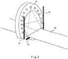
- Fig. 2 shows a structural diagram of an embodiment of an apparatus for ray scanning imaging according to the present invention.
- the apparatus for ray scanning imaging comprises a ray detection device and a plurality of ray generators 21.
- the plurality of ray generators 21 can emit the ray beams in sequence to the object to be inspected, to perform scanning for a single slice of the object to be inspected.
- the ray detection device is arranged in a multi-segmental semi-closed configuration.
- the description is made by taking a ray detection device in the multi-segmental semi-closed adjoining configuration composed of a plurality of linear arrays of ray detectors.
- the plurality of ray generators 21 is distributed along a specific shape such that the object to be inspected passes through the space formed by the specific shape.
- the plurality of ray generators 21 are distributed uniformly along a circular arc.
- the central angle of the circular arc is at least ⁇ +2 ⁇ , where 2 ⁇ is a complete fan angle of a fan ray beam.
- a plurality of linear arrays of ray detectors in a segmented manner are adjoined.
- a linear array 22 of ray detectors, a linear array 23 of ray detectors, and a linear array 24 of ray detectors adjoin end to end in a same plane in sequence except that the linear array 22 of ray detectors and the linear array 24 of ray detectors do not adjoin each other, so as to form an inverted doorframe-shaped semi-closed frame.
- Each of these linear arrays of ray detectors includes a plurality of ray detection units arranged along a straight line.
- a delivery device 25 may be used to carry the object to be inspected to pass through the scanning region.
- the plurality of ray generators 21 emit the ray beams in sequence to the object to be inspected, so as to complete scan for a single slice.
- these ray beams are collected by these linear arrays of ray detectors. By processing these collected ray values, a reconstructed image of the object to be inspected can be obtained.
- a plane where the plurality of linear arrays of ray detectors are placed and a plane where the plurality of ray generators 21 are placed should be two different ones.
- the two planes may be in parallel with each other and both perpendicular to a movement direction of the object to be inspected.
- crosstalk and radiation blind zone among these detection units may be avoided.
- These conditions of data completeness includes, firstly, a condition of angle completeness, that is, a ray radiation angle for the object to be inspected is at least ⁇ +2 ⁇ , where 2 ⁇ is a complete fan angle of the fan ray beam; and, secondly, a condition of ensuring that ray values collected by the ray detectors are not truncated under all scanning angles, i.e., a condition of ensuring that all the ray beams emitted by these ray generators can be detected effectively by these ray detectors under all these scanning angles.
- each of the ray generators 21 can be a fan beam with a fan angle of 2 ⁇ .
- the ray beam can have other form, instead of a fan form.
- each ray generator 21 is provided with one or more ray emission openings each emitting a straight line-shaped ray beam.
- these ray emission openings of each ray generator 21 can emit a unit of parallel ray beams.
- X-ray generator or other types of ray generators, may be used as the ray generator 21.
- carbon nanotube X-ray generator may be used as the ray generation source.
- the carbon nanotube X-ray generator has the advantages, such as ray emission generation without under high temperature, quicker switch on and off, and less volume. Ray imaging speed is efficiently enhanced when multiple angle radiation of the carbon nanotube X-ray generator on the object to be inspected is performed.
- the carbon nanotube X-ray generator refers to these following documents, G.Z.Yue,Q.Qiu,B.Gao,et al.
- the central angle of the circular arc on which the plurality of ray generators 21 are arranged is ⁇ +2 ⁇ in the embodiment. That is, the ray generators 21 perform the scanning on the object to be inspected within an angle range of ⁇ +2 ⁇ . In other words, configuration of these ray generators 21 fulfills the requirement for the angle completeness condition of these conditions of data completeness.
- the plurality of ray generators 21 are disposed in an annular semi-closed configuration and the linear array 22 of ray detectors, the linear array 23 of ray detectors, and the linear array 24 of ray detectors form a corresponding frame-shaped semi-closed configuration, so that all the ray beams generated from each of the ray generators can be detected effectively by these linear arrays of ray detectors.
- such configuration fulfills the second requirement of these conditions of data completeness.
- the dual-layer dual-energy energy detection unit may be used as the ray detection unit.
- any types of detection units may also be used as the ray detection unit, for example, monoenergy detection unit, multiple energy detection unit, or, true-dual energy detection unit.
- the adopted dual-layer dual-energy energy detection unit comprises two layers of crystals and a filter between the two layers of crystals.
- the filter may be a copper filter.
- a first layer of crystals is used to achieve low energy ray values while a second layer of crystals is used to achieve reshaped high energy ray values.
- This type dual-layer dual-energy energy detection unit has advantages such as high quality, lower price, and ease to be widely used.
- the number of the linear arrays of ray detectors is not limited to three, as shown in Fig. 2 .
- four or more linear arrays of ray detectors may be adopted to collect the ray values.
- the angle between every two adjacent linear arrays of ray detectors should be greater than ⁇ /2.
- the number, angles and lengths of the linear arrays of ray detectors can also be adjusted in accordance with factors, such as volume, shape, etc., of the object to be inspected, although the used linear arrays of ray detectors above all should fulfill the conditions of data completeness.
- the plurality of linear arrays of ray detectors not only collects completely ray projection values, but also possesses higher performance-to-price ratio compared with the conventional circular arc array of detectors.
- the plurality of linear arrays of ray detectors according to the present invention may form a greater inner space and allow passage of the object to be inspected with greater volume, and, provided that there is same size of the inner spaces, such structural configuration according to the present invention adopts less detection units and reduces the cost.
- the apparatus for ray scanning imaging may further comprise an imaging unit, which may achieve a tomography image for the object to be inspected by processing ray detection values collected by the linear arrays of ray detectors.
- ray detection values collected by the linear arrays of ray detectors may also be sent to, via a date delivery system, and numerically processed by a main control and data processing terminal.
- Standard fan beam weighted filtered back projection (FBP) reconstruction method is only applicable to two kinds of detection unit arrangements, one is an equiangular configuration, that is, these multiple detection units are arranged in a circular arc manner and the angles between beams corresponding to every detection units are equivalent to each other, and the other is an equidistant configuration, that is, these multiple detection units are arranged in a straight line-shaped and the distances from one detection unit to its adjacent detection unit are equivalent to each other and central axis of ray beam emitted by every ray generator is perpendicular to a straight line where multiple detection units are arranged.
- a method which is similar to the above-mentioned reconstruction method may be adopted and will not be described here.
- arrangement of detection units corresponding to some of these ray generators does not fulfill the equidistant configuration requirement for the above-mentioned reconstruction method, because of adoptions of the annular configuration of these ray generators and the multi-segmental semi-closed configuration of these linear arrays of ray detectors.
- these ray detection units corresponding to some of these ray generators are not arranged in a straight line that is perpendicular to the central axis of ray beam emitted by such ray generators. The followings are explanations and illustrations of such arrangement with reference to Fig. 3 and Fig. 4 .
- Fig. 3 shows the diagram of a positional relationship between ray generators and linear arrays of ray detectors in the embodiment.
- all these ray detection units corresponding to a ray generator A are located on the linear array 24 of ray detectors, and a straight line where these ray detection units are arranged is perpendicular to central axis of the ray beams emitted by the ray generator A, and distances from one detection unit to its adjacent detection unit are equivalent to each other. That is to say, to the ray generator A, these ray detection units are arranged in the equidistant configuration required for standard fan beam FBP reconstruction method.
- the circular arc where the plurality of ray generators is arranged is divided into five regions, in which, the ray beams emitted from these ray generators in a first region are collected only by the linear array 24 of ray detectors at the right side, the ray beams emitted from these ray generators in a second region are collected both by the linear array 24 of ray detectors at the right side and the linear array 23 of ray detectors at the bottom, the ray beams emitted from these ray generators in a third region are collected only by the linear array 23 of ray detectors at the bottom, the ray beams emitted from these ray generators in a fourth region are collected both by the linear array 22 of ray detectors at the left side and the linear array 23 of ray detectors at the bottom, and, the ray beams emitted from these ray generators in a fifth region are collected only by the linear array 22 of ray detectors at the left side.
- Fig. 4A is a diagram of a positional relationship among ray generator, ray detectors and virtual ray detectors in the first region.
- the array 24 of real ray detectors is perpendicular to central axis of the ray beams emitted by the ray generators A but is not perpendicular to central axis of the ray beams emitted by the ray generator D. Accordingly, for the ray generator D, the ray values of the ray beams collected by the array 24 of ray detectors are not the equidistant ray collecting values.
- ⁇ is a sampling angle corresponding to the projection data
- 2 ⁇ is a maximum fan angle for fan ray beam.
- the imaging unit may employ a linear array 24' of equidistant virtual ray detectors corresponding to the ray generator D, for the ray generator D.
- the linear array 24' of equidistant virtual detectors may comprise a plurality of virtual detection units arranged along a straight line and distributed equidistantly.
- the linear array 24' of equidistant virtual detectors is perpendicular to central axis of the ray beams emitted by the ray generator D.
- the imaging unit determines a ray detection unit m1 corresponding to the virtual detection units n1, and achieves ray detection value of the virtual detection unit n1 on the basis of that of the ray detection unit m1.
- Other virtual detection units on the linear array 24' of equidistant virtual ray detectors may be achieved in the above manner.
- Fig. 4B is a diagram of a positional relationship among ray generator E, arrays of ray detectors and virtual ray detectors in the second region.
- the ray beams emitted by the ray generator E in the second region are collected commonly by linear array 24 of ray detectors at the right side and the linear array 23 of ray detectors at the bottom, and, the ray values of the ray beams collected are not the equidistant ray collecting values.
- the imaging unit provides a linear array 23' of virtual ray detectors and a linear array 24' of virtual ray detectors both combined and arranged along a straight line.
- the imaging unit determines a ray detection unit m2 corresponding to the virtual detection units n2 and a ray detection unit m3 corresponding to the virtual detection units n3, and may achieve ray detection values of the virtual detection units n2 and n3 on the basis of those of the ray detection units m2 and m3.
- some virtual ray detection units may be non-equidistant, or, one real ray detection unit corresponds to a plurality of virtual ray detection units.
- a post process may be done after a final image is obtained, or, positions of the plurality of virtual ray detection units may be adjusted in a suitable method so as to fulfill the equidistant requirements among these virtual ray detection units.
- Distances between every ray generator and its corresponding linear array of equidistant virtual detectors are also equal to each other.
- such distance may be set as the one between the ray generator A and the linear array 24 of ray detectors.
- an equidistant fan beam projection value is composed of the ray detection values of all these linear arrays of equidistant virtual detectors and the linear arrays of detectors corresponding to the ray generators A, B, and C.
- the imaging unit can achieve dual-energy decomposition coefficients of different basis materials by dual-energy decomposing the equidistant fan beam projection values. Then, the image for the object to be inspected can be achieved by, with a filtered back projection algorithm, dual-energy reconstructing dual-energy decomposition coefficients of different basis materials.
- the apparatus may further comprise a database which may store atomic numbers and electron densities of suspicious items therein.
- the imaging unit determines whether the object to be inspected is suspicious item or not, by comparing distributions of atomic number and electron density of the object to be inspected that is achieved in the dual-energy reconstruction with those of suspicious items in the database.
- the apparatus can achieve the scanning imaging of the object to be inspected, without a gantry mechanism.
- the plurality of ray generators emit the ray beams in sequence to the object to be inspected, and the linear arrays of ray detectors are used for collection of these ray projection values, so as to complete scan for a single slice.
- this apparatus can obtain rapidly the complete ray projection values without rotations thereof, such that the inspection time is shortened effectively.
- the apparatus according to the present invention without the gantry mechanism, has the advantages such as less volume of the whole apparatus, less cost, and higher quality of the achieved image for the object to be inspected due to avoiding non-distinct imaging issues caused during the rotation.
- the technical solution according to the present invention adopts linear arrays of dual-layer dual-energy detectors together with scanning and reconstruction of short scan CT, which reduces effectively influence of shielding of luggage and goods on the safety inspection operation.
- Fig. 5 shows a structural diagram of an example of an apparatus for ray scanning imaging which is not according to the present invention.
- the apparatus comprises a ray detection device 32 and a plurality of ray generators 31.
- the plurality of ray generators 31 are distributed uniformly along the circular arc.
- the central angle of the circular arc 312 is at least 180°.
- the plurality of ray generators 31 may emit ray beams simultaneously to an object to be inspected within a single scanning period.
- the ray beams are detected by the ray detection device 32 after passing through the object to be inspected.
- Every ray generator 31 can be provided with a plurality of ray emission units.
- each ray generator 31 is provided with five ray emission units 311.
- the five ray emission units 311 may emit parallel straight line-shaped ray beams simultaneously, to form a unit of ray beams.
- overlapping regions among the plurality of units of ray beams serve as the scanning region 313 (Field of View, FOV).
- the detection device 32 comprises a plurality of ray detection units 321.
- the plurality of ray detection units 321 are distributed uniformly along the circular arc 322.
- a radius of the circular arc 322 is equal to that of the circular arc 312 while a central angle of the circular arc 322 is a straight angle.
- the ray emission units 311 on the ray generators 31 corresponds one by one to the ray receipt units 312 on the ray detection device 32.
- the ray beams emitted by all the ray emission units 311 are not overlapped with each other when impinging on the ray detection device.
- a tomography scan is performed on this object to be inspected.
- the parallel ray beam projection value is composed of ray detection values achieved by this device.
- a plane where the ray detection device 32 is placed and a plane where the ray generators 31 are placed should be two different ones.
- the two planes are in parallel with each other and are both perpendicular to a movement direction of the object to be inspected.
- the imaging unit then, processes the ray detection values collected by the ray detection device 32, so as to obtain image for the object to be inspected.
- the dual-energy decomposition coefficients of different basis materials may be achieved by directly dual-energy decomposing the parallel beam projection values, and, an image for the object to be inspected may be achieved by, with a filtered back projection algorithm, dual-energy reconstructing dual-energy decomposition coefficients of different basis materials.
- the imaging unit may also achieve atomic number and electron density of the object to be inspected in the dual-energy reconstruction and determine whether the object to be inspected is suspicious item or not, by comparing the atomic number and electron density of the object to be inspected with those of suspicious items in the database.
- the apparatus may adopt any structures and configurations with which it is ensured that the ray beams emitted by all these ray emission units would not be overlapped with each other when impinging on the ray detection device and is not limited to those structures and configurations shown in the drawings. That is, situations that the ray beams emitted by two or more ray emission units 311 are collected simultaneously by one ray detection unit 321 should be avoided.
- central angle of the circular arc 322 may be larger than that of the circular arc 312 along which the plurality of ray generators are arranged, radius of the circular arc 322 may be larger than that of the circular arc 321, and, the number of the ray detection units 321 may be more than that of the ray emission units.
- the ray detection device 32 may be in any other configuration, instead of the circular arc configuration.
- the ray detection device 32 may be arranged in a three sectional or multi-sectional manner as in the above embodiments so long as the ray beams emitted by all these ray emission units 311 would not be overlapped with each other when impinging on the ray detection device 32.
- virtual detection units corresponding to the real detection units should be achieved, and detection values of these virtual detection units are achieved based on those of the real detection units. Then, the image for the object to be inspected is obtained by performing a reconstruction by the ray detection values of these virtual detection units.
- the plurality of emission units 311 of the apparatus can emit ray beams simultaneously towards the object to be inspected, so that the inspection time for the object to be inspected is shortened effectively, so as to greatly shorten its clearance time.
- Fig. 6 is a flow diagram of an embodiment of a method for ray scanning imaging according to the present invention.
- a ray scanning on the object to be inspected is performed to achieve ray detection values.
- the scanning and detection is performed by using any one of the apparatuses for ray scanning imaging according to the present invention.
- a plurality of ray generators may emit ray beams in sequence to an object to be inspected, to complete scan for a single slice.
- a ray detection device collects these ray beams and achieve ray detection values.
- these ray detection values are rearranged to achieve equidistant fan beam projection values.
- pretreatment and correction of these ray detection values which includes these operations like elimination of air value and local negative logarithm calculation, uniformity correction, determination and removal of detector' bad track, etc., may be performed.
- the followings relates to the description made by taking a ray detection device formed of a plurality of linear arrays of ray detectors, and a fan ray beam as an example. Suitable adjustments may be made to the ray beams of any other form, with reference to this method.
- linear array of equidistant virtual detectors may be provided for each of these ray generators.
- the linear array of equidistant virtual detectors may comprise multiple virtual detection units arranged along a straight line and distributed equidistantly.
- the ray detection units corresponding to the virtual detection units are determined respectively, and, ray detection values of the virtual detection units are achieved on the basis of those of the ray detection units.
- An equidistant fan beam projection value is composed of the ray detection values of all these linear arrays of equidistant virtual detectors and the linear arrays of detectors corresponding to the ray generators A, B, and C.
- the method of ray scanning imaging may further comprises the following steps.
- a step S13 of achieving dual-energy decomposition coefficients of different basis materials by dual-energy decomposing the equidistant fan beam projection values is included.
- the dual-energy decomposition coefficients A1 and A2 of different basis materials can be achieved by dual-energy decomposing the equidistant fan beam projection values, with a basis material decomposition method.
- a step S14 of achieving image for the object to be inspected, by, with a filtered back projection algorithm, dual-energy reconstructing dual-energy decomposition coefficients of different basis materials is included.
- the reconstructed dual-energy reconstruction coefficients a1 and a2 can be achieved respectively by performing a CT reconstruction of the dual-energy decomposition coefficients A1 and A2 in accordance with a short scan and weighted reconstruction method, and, the weighted coefficient can be achieved by the following formula:
- ⁇ is a sampling angle corresponding to the projection data
- 2 ⁇ is a maximum fan angle for fan ray beam.
- the used weighted coefficient can be achieved by utilizing any other suitable methods, instead of the above formula.
- this method may still further comprise the following steps.
- a step S15 of determining whether the object to be inspected is suspicious item or not is included.
- the dual-energy reconstruction coefficients a1 and a2 may be substituted into the following two formulas (1) and (2), in which Z 1 and Z 2 are the atomic number of two basis materials, respectively, and, ⁇ e1 and ⁇ e2 are the electron density values of two basis materials, respectively.
- distribution values of the atomic number and electron density of the object to be inspected are compared with those of suspicious items, so as to determine whether the object to be inspected is suspicious item or not.
- Distributions of atomic numbers and electron densities of suspicious items can be stored in the database or other devices.
- these dangerous suspicious items such as combustible goods, explosive goods, narcotic drugs, etc., can be recognized quickly and accurately.
Landscapes
- Health & Medical Sciences (AREA)
- Life Sciences & Earth Sciences (AREA)
- Engineering & Computer Science (AREA)
- Physics & Mathematics (AREA)
- Medical Informatics (AREA)
- High Energy & Nuclear Physics (AREA)
- Molecular Biology (AREA)
- General Health & Medical Sciences (AREA)
- Nuclear Medicine, Radiotherapy & Molecular Imaging (AREA)
- Radiology & Medical Imaging (AREA)
- Pathology (AREA)
- Optics & Photonics (AREA)
- Biomedical Technology (AREA)
- Surgery (AREA)
- Animal Behavior & Ethology (AREA)
- Biophysics (AREA)
- Public Health (AREA)
- Veterinary Medicine (AREA)
- Heart & Thoracic Surgery (AREA)
- General Physics & Mathematics (AREA)
- Pulmonology (AREA)
- Theoretical Computer Science (AREA)
- General Life Sciences & Earth Sciences (AREA)
- Geophysics (AREA)
- Spectroscopy & Molecular Physics (AREA)
- Mathematical Physics (AREA)
- Chemical & Material Sciences (AREA)
- Analytical Chemistry (AREA)
- Biochemistry (AREA)
- Immunology (AREA)
- Analysing Materials By The Use Of Radiation (AREA)
- Apparatus For Radiation Diagnosis (AREA)
Description
- The present invention relates to a radiation imaging field, and in particular, to apparatus and method for ray scanning imaging.
- Nowadays radiation imaging apparatus has been widely utilized in public places and important departments, such as airports, stations, customs, subways, harbors, etc., for performing security inspection of goods such as luggage or cargo in a high efficient and stable manner as all the countries in the world pay more attention on security inspection.
- Radiation imaging apparatus is generally made in accordance with principles of exponential ray attenuation. That is, scanning of the object to be inspected is carried out by the ray beams emitted from the radiation source. The ray beams pass through the object to be inspected, and are received by the ray collection device. Three-dimensional images are composed or reconstructed and displayed based on ray detection values received by the ray collection device.
-
Fig. 1 shows a structural diagram of a prior art radiation imaging apparatus. - The radiation imaging apparatus comprises a
gantry 13, aray source 11 connected to thegantry 13, adetection arrangement 12 placed, opposite to theray source 11, on thegantry 13, and adelivery device 14 for delivery of the object to be inspected. During the inspection operation, thegantry 13 brings theray source 11 and thedetection arrangement 12 to rotate so as to achieve ray projection values for different rays under different angles and to obtain tomography images for the object to be inspected by means of reconstruction. - The applicant has made in-depth study on the prior art radiation imaging apparatus and found that, the prior art radiation imaging apparatus has low detection efficiency because rotations of the
ray source 11 and thedetection arrangement 12 are brought by thegantry 13 with a limited rotational speed. Accordingly, the prior art radiation imaging apparatus is hard to satisfy the existing requirements, for example, the requirement of a clearance rate of 0.5 m/s, for civil aviation goods. -
WO 97/18462 A1 -
WO2010/138574 A1 discloses a baggage scanning system comprising a number of x-ray sources spaced around a scanning region in a circular arrangement and a circular detector array. Similar scanning systems are disclosed inUS2005/111610 A1 ,US7233644 B1 andWO2010/103331 A1 . - In order to solve the issue of low detection efficiency existing in the prior art radiation imaging apparatus, the inventors of the present invention has proposed a new technical solution.
- Accordingly, it is an object of the present invention to provide an apparatus for ray scanning imaging, which effectively shortens inspection time for an object to be inspected.
- Accordingly, it is another object of the present invention to provide a method for ray scanning imaging, which achieves and processes ray collection values to obtain an image for an object to be inspected, by means of such apparatus for ray scanning imaging.
- Aspects of the present invention are defined by the independent claims and preferred embodiments are defined by the dependent claims.
- The accompanying drawings which constitute a part of the description will illustrate the embodiments of the present invention, and, together with the others of the description, will set forth principles of the present invention.
- These and/or other aspects and advantages of the invention will become more apparent and more readily appreciated from the following description of the embodiments, taken in conjunction with the accompanying drawings of which:
-
FIG. 1 is a structural diagram of a prior art apparatus for ray scanning imaging; -
Fig. 2 is a structural diagram of an embodiment of an apparatus for ray scanning imaging according to the present invention; -
Fig. 3 is a diagram showing a positional relationship between ray generators and linear arrays of ray detectors in the embodiment of the apparatus for ray scanning imaging according to the present invention; -
Figs. 4A and 4B are diagrams respectively showing a positional relationship among ray generators, ray detectors and virtual ray detectors, in different regions; -
Fig. 5 is a structural diagram of an example of an apparatus for ray scanning imaging which is not according to the present invention; and -
Fig. 6 is a flow diagram of an embodiment of a method for processing ray detection values according to the present invention. - Reference will now be made in detail to exemplary embodiments of the present specification, taken in conjunction with the accompanying drawings.
- Meanwhile, it should be understood that, these figures in the accompanying drawings may not be drawn to scale, helping to description of the present invention.
- The following description is presented only by way of illustrations.
- Known technologies, methods and apparatuses for those skilled in the art may be not discussed in detail, excluding, in some suitable situations, those seen as parts of the present specification.
- In these exemplary embodiments described and illustrated below, any specific values are explained only by way of representation and no limitations. Accordingly, different values may be adopted in alternative examples of these exemplary embodiments.
- It should be noted that like reference numbers and characters may have been used throughout these figures to denote like parts. Accordingly, once definition of one reference number/character is made in one figure, no further explanations are required in its succeeding figures.
-
Fig. 2 shows a structural diagram of an embodiment of an apparatus for ray scanning imaging according to the present invention. - The apparatus for ray scanning imaging comprises a ray detection device and a plurality of
ray generators 21. - When an object to be inspected is brought to the scanning region of the apparatus, the plurality of
ray generators 21 can emit the ray beams in sequence to the object to be inspected, to perform scanning for a single slice of the object to be inspected. - After passing through the object to be inspected, all the ray beams are collected by the ray detection device.
- The ray detection device is arranged in a multi-segmental semi-closed configuration. In this embodiment, the description is made by taking a ray detection device in the multi-segmental semi-closed adjoining configuration composed of a plurality of linear arrays of ray detectors.
- The plurality of
ray generators 21 is distributed along a specific shape such that the object to be inspected passes through the space formed by the specific shape. In this embodiment, the plurality ofray generators 21 are distributed uniformly along a circular arc. The central angle of the circular arc is at least π+2γ, where 2γ is a complete fan angle of a fan ray beam. - In this embodiment, a plurality of linear arrays of ray detectors in a segmented manner are adjoined. Specifically, a
linear array 22 of ray detectors, alinear array 23 of ray detectors, and alinear array 24 of ray detectors adjoin end to end in a same plane in sequence except that thelinear array 22 of ray detectors and thelinear array 24 of ray detectors do not adjoin each other, so as to form an inverted doorframe-shaped semi-closed frame. Each of these linear arrays of ray detectors includes a plurality of ray detection units arranged along a straight line. - A
delivery device 25 may be used to carry the object to be inspected to pass through the scanning region. Within a single scanning period, the plurality ofray generators 21 emit the ray beams in sequence to the object to be inspected, so as to complete scan for a single slice. After passing through the objected to be inspected, these ray beams are collected by these linear arrays of ray detectors. By processing these collected ray values, a reconstructed image of the object to be inspected can be obtained. - A plane where the plurality of linear arrays of ray detectors are placed and a plane where the plurality of
ray generators 21 are placed should be two different ones. - Preferably, the two planes may be in parallel with each other and both perpendicular to a movement direction of the object to be inspected. Thus, crosstalk and radiation blind zone among these detection units may be avoided.
- Next, the conditions of data completeness required for accurate reconstruction by use of the fan ray beams will be explained. These conditions of data completeness includes, firstly, a condition of angle completeness, that is, a ray radiation angle for the object to be inspected is at least π+2γ, where 2γ is a complete fan angle of the fan ray beam; and, secondly, a condition of ensuring that ray values collected by the ray detectors are not truncated under all scanning angles, i.e., a condition of ensuring that all the ray beams emitted by these ray generators can be detected effectively by these ray detectors under all these scanning angles.
- In this embodiment, the ray beam emitted by each of the
ray generators 21 can be a fan beam with a fan angle of 2γ. Of course, the ray beam can have other form, instead of a fan form. For example, in accordance with practical requirement, eachray generator 21 is provided with one or more ray emission openings each emitting a straight line-shaped ray beam. Thus, these ray emission openings of eachray generator 21 can emit a unit of parallel ray beams. - X-ray generator, or other types of ray generators, may be used as the
ray generator 21. Preferably, in this embodiment, carbon nanotube X-ray generator may be used as the ray generation source. Compared with those conventional X-ray machines, the carbon nanotube X-ray generator has the advantages, such as ray emission generation without under high temperature, quicker switch on and off, and less volume. Ray imaging speed is efficiently enhanced when multiple angle radiation of the carbon nanotube X-ray generator on the object to be inspected is performed. For details of the carbon nanotube X-ray generator, refers to these following documents, G.Z.Yue,Q.Qiu,B.Gao,et al. Generation of continuous and pulsed diagnostic imaging x-ray radiation using a carbon-nanotube-based field-emission cathode.Appi.Phys.Lett.81,355(2002);doi:10.1063/1.1492305, and the detailed description is omitted herein. - The central angle of the circular arc on which the plurality of
ray generators 21 are arranged is π+2γ in the embodiment. That is, theray generators 21 perform the scanning on the object to be inspected within an angle range of π+2γ. In other words, configuration of theseray generators 21 fulfills the requirement for the angle completeness condition of these conditions of data completeness. - As to the second requirement of these conditions of data completeness, the plurality of
ray generators 21 are disposed in an annular semi-closed configuration and thelinear array 22 of ray detectors, thelinear array 23 of ray detectors, and thelinear array 24 of ray detectors form a corresponding frame-shaped semi-closed configuration, so that all the ray beams generated from each of the ray generators can be detected effectively by these linear arrays of ray detectors. Thus, such configuration fulfills the second requirement of these conditions of data completeness. - The dual-layer dual-energy energy detection unit may be used as the ray detection unit. Of course, any types of detection units may also be used as the ray detection unit, for example, monoenergy detection unit, multiple energy detection unit, or, true-dual energy detection unit.
- The adopted dual-layer dual-energy energy detection unit comprises two layers of crystals and a filter between the two layers of crystals. The filter may be a copper filter. A first layer of crystals is used to achieve low energy ray values while a second layer of crystals is used to achieve reshaped high energy ray values. This type dual-layer dual-energy energy detection unit has advantages such as high quality, lower price, and ease to be widely used.
- It should be noted that the number of the linear arrays of ray detectors is not limited to three, as shown in
Fig. 2 . For example, four or more linear arrays of ray detectors may be adopted to collect the ray values. In such case, the angle between every two adjacent linear arrays of ray detectors should be greater than π/2. - The number, angles and lengths of the linear arrays of ray detectors can also be adjusted in accordance with factors, such as volume, shape, etc., of the object to be inspected, although the used linear arrays of ray detectors above all should fulfill the conditions of data completeness.
- As adopting a multi-segmental semi-closed frame configuration, the plurality of linear arrays of ray detectors not only collects completely ray projection values, but also possesses higher performance-to-price ratio compared with the conventional circular arc array of detectors. Specifically, provided that there is same number of the detection units, the plurality of linear arrays of ray detectors according to the present invention may form a greater inner space and allow passage of the object to be inspected with greater volume, and, provided that there is same size of the inner spaces, such structural configuration according to the present invention adopts less detection units and reduces the cost.
- The apparatus for ray scanning imaging may further comprise an imaging unit, which may achieve a tomography image for the object to be inspected by processing ray detection values collected by the linear arrays of ray detectors.
- Of course, ray detection values collected by the linear arrays of ray detectors may also be sent to, via a date delivery system, and numerically processed by a main control and data processing terminal.
- Before introducing detailed description of the data processing, the structural requirements of the reconstruction method on the ray detection units under fan ray beams will be explained.
- Standard fan beam weighted filtered back projection (FBP) reconstruction method is only applicable to two kinds of detection unit arrangements, one is an equiangular configuration, that is, these multiple detection units are arranged in a circular arc manner and the angles between beams corresponding to every detection units are equivalent to each other, and the other is an equidistant configuration, that is, these multiple detection units are arranged in a straight line-shaped and the distances from one detection unit to its adjacent detection unit are equivalent to each other and central axis of ray beam emitted by every ray generator is perpendicular to a straight line where multiple detection units are arranged. In case that unit of ray beams in a straight line is used, a method which is similar to the above-mentioned reconstruction method may be adopted and will not be described here.
- In this embodiment, arrangement of detection units corresponding to some of these ray generators does not fulfill the equidistant configuration requirement for the above-mentioned reconstruction method, because of adoptions of the annular configuration of these ray generators and the multi-segmental semi-closed configuration of these linear arrays of ray detectors. Specifically, these ray detection units corresponding to some of these ray generators are not arranged in a straight line that is perpendicular to the central axis of ray beam emitted by such ray generators. The followings are explanations and illustrations of such arrangement with reference to
Fig. 3 andFig. 4 . -
Fig. 3 shows the diagram of a positional relationship between ray generators and linear arrays of ray detectors in the embodiment. - As shown in
Fig. 3 , all these ray detection units corresponding to a ray generator A are located on thelinear array 24 of ray detectors, and a straight line where these ray detection units are arranged is perpendicular to central axis of the ray beams emitted by the ray generator A, and distances from one detection unit to its adjacent detection unit are equivalent to each other. That is to say, to the ray generator A, these ray detection units are arranged in the equidistant configuration required for standard fan beam FBP reconstruction method. - Similarly, there are some ray detection units corresponding to the ray generators B and C, respectively. Whatever, all these ray detection units corresponding to the rest of these ray generators are not arranged in the equidistant configuration required for standard fan beam FBP reconstruction method.
- In order to further explain and illustrate such configuration, provided that the circular arc where the plurality of ray generators is arranged is divided into five regions, in which, the ray beams emitted from these ray generators in a first region are collected only by the
linear array 24 of ray detectors at the right side, the ray beams emitted from these ray generators in a second region are collected both by thelinear array 24 of ray detectors at the right side and thelinear array 23 of ray detectors at the bottom, the ray beams emitted from these ray generators in a third region are collected only by thelinear array 23 of ray detectors at the bottom, the ray beams emitted from these ray generators in a fourth region are collected both by thelinear array 22 of ray detectors at the left side and thelinear array 23 of ray detectors at the bottom, and, the ray beams emitted from these ray generators in a fifth region are collected only by thelinear array 22 of ray detectors at the left side. - Taking the ray generator in the first region and its corresponding ray detectors as an example, the situation where the collected ray values are non-equidistant ray collected values is explained hereinafter.
-
Fig. 4A is a diagram of a positional relationship among ray generator, ray detectors and virtual ray detectors in the first region. - As shown in
Fig. 4A , thearray 24 of real ray detectors is perpendicular to central axis of the ray beams emitted by the ray generators A but is not perpendicular to central axis of the ray beams emitted by the ray generator D. Accordingly, for the ray generator D, the ray values of the ray beams collected by thearray 24 of ray detectors are not the equidistant ray collecting values. In this embodiment, β is a sampling angle corresponding to the projection data, and 2γ is a maximum fan angle for fan ray beam. - In order to solve this problem, the imaging unit may employ a linear array 24' of equidistant virtual ray detectors corresponding to the ray generator D, for the ray generator D.
- The linear array 24' of equidistant virtual detectors may comprise a plurality of virtual detection units arranged along a straight line and distributed equidistantly. The linear array 24' of equidistant virtual detectors is perpendicular to central axis of the ray beams emitted by the ray generator D.
- Then the imaging unit, in accordance with connection lines between the ray generator D and the
ray detection unit 24, determines a ray detection unit m1 corresponding to the virtual detection units n1, and achieves ray detection value of the virtual detection unit n1 on the basis of that of the ray detection unit m1. Other virtual detection units on the linear array 24' of equidistant virtual ray detectors may be achieved in the above manner. -
Fig. 4B is a diagram of a positional relationship among ray generator E, arrays of ray detectors and virtual ray detectors in the second region. - In
Fig. 4B , the ray beams emitted by the ray generator E in the second region are collected commonly bylinear array 24 of ray detectors at the right side and thelinear array 23 of ray detectors at the bottom, and, the ray values of the ray beams collected are not the equidistant ray collecting values. - Similar to those in
Fig. 4A , in order to achieve the equidistant ray collecting values, the imaging unit provides a linear array 23' of virtual ray detectors and a linear array 24' of virtual ray detectors both combined and arranged along a straight line. - Then, the imaging unit, in accordance with connection lines between the ray generator E and the
ray detection unit 23 and theray detection unit 24, determines a ray detection unit m2 corresponding to the virtual detection units n2 and a ray detection unit m3 corresponding to the virtual detection units n3, and may achieve ray detection values of the virtual detection units n2 and n3 on the basis of those of the ray detection units m2 and m3. - Other linear arrays of ray detectors corresponding to the ray generators in the third region to the fifth region may be achieved in a similar manner, and their descriptions are omitted for clarity.
- It should be noted that, in the linear array of equidistant virtual detectors achieved by the above-mentioned method, some virtual ray detection units may be non-equidistant, or, one real ray detection unit corresponds to a plurality of virtual ray detection units. In these cases, a post process may be done after a final image is obtained, or, positions of the plurality of virtual ray detection units may be adjusted in a suitable method so as to fulfill the equidistant requirements among these virtual ray detection units.
- Distances between every ray generator and its corresponding linear array of equidistant virtual detectors are also equal to each other. For example, such distance may be set as the one between the ray generator A and the
linear array 24 of ray detectors. - In this way, an equidistant fan beam projection value is composed of the ray detection values of all these linear arrays of equidistant virtual detectors and the linear arrays of detectors corresponding to the ray generators A, B, and C.
- Provided that the ray detection units are dual-layer dual-energy energy detection units, the imaging unit can achieve dual-energy decomposition coefficients of different basis materials by dual-energy decomposing the equidistant fan beam projection values. Then, the image for the object to be inspected can be achieved by, with a filtered back projection algorithm, dual-energy reconstructing dual-energy decomposition coefficients of different basis materials.
- The apparatus may further comprise a database which may store atomic numbers and electron densities of suspicious items therein. The imaging unit determines whether the object to be inspected is suspicious item or not, by comparing distributions of atomic number and electron density of the object to be inspected that is achieved in the dual-energy reconstruction with those of suspicious items in the database.
- Accordingly, the apparatus according to the present invention can achieve the scanning imaging of the object to be inspected, without a gantry mechanism. Within a single scanning period, the plurality of ray generators emit the ray beams in sequence to the object to be inspected, and the linear arrays of ray detectors are used for collection of these ray projection values, so as to complete scan for a single slice. During the whole inspection operation, this apparatus can obtain rapidly the complete ray projection values without rotations thereof, such that the inspection time is shortened effectively.
- Further, the apparatus according to the present invention, without the gantry mechanism, has the advantages such as less volume of the whole apparatus, less cost, and higher quality of the achieved image for the object to be inspected due to avoiding non-distinct imaging issues caused during the rotation.
- Still further, the technical solution according to the present invention adopts linear arrays of dual-layer dual-energy detectors together with scanning and reconstruction of short scan CT, which reduces effectively influence of shielding of luggage and goods on the safety inspection operation.
-
Fig. 5 shows a structural diagram of an example of an apparatus for ray scanning imaging which is not according to the present invention. - The apparatus comprises a
ray detection device 32 and a plurality ofray generators 31. - The plurality of
ray generators 31 are distributed uniformly along the circular arc. The central angle of thecircular arc 312 is at least 180°. The plurality ofray generators 31 may emit ray beams simultaneously to an object to be inspected within a single scanning period. The ray beams are detected by theray detection device 32 after passing through the object to be inspected. - Every
ray generator 31 can be provided with a plurality of ray emission units. In this example, eachray generator 31 is provided with fiveray emission units 311. The fiveray emission units 311 may emit parallel straight line-shaped ray beams simultaneously, to form a unit of ray beams. As shown in the figure, overlapping regions among the plurality of units of ray beams serve as the scanning region 313 (Field of View, FOV). - Correspondingly, the
detection device 32 comprises a plurality ofray detection units 321. The plurality ofray detection units 321 are distributed uniformly along thecircular arc 322. A radius of thecircular arc 322 is equal to that of thecircular arc 312 while a central angle of thecircular arc 322 is a straight angle. Accordingly, theray emission units 311 on theray generators 31 corresponds one by one to theray receipt units 312 on theray detection device 32. In this way, the ray beams emitted by all theray emission units 311 are not overlapped with each other when impinging on the ray detection device. When an object to be inspected passes through thescanning region 313, a tomography scan is performed on this object to be inspected. The parallel ray beam projection value is composed of ray detection values achieved by this device. - A plane where the
ray detection device 32 is placed and a plane where theray generators 31 are placed should be two different ones. Preferably, the two planes are in parallel with each other and are both perpendicular to a movement direction of the object to be inspected. - The imaging unit, then, processes the ray detection values collected by the
ray detection device 32, so as to obtain image for the object to be inspected. - It is not needed, in this example, to rearrange these achieved ray detection values since distances between all the
ray emission units 311 and correspondingray detection units 321 are equal to one another. The dual-energy decomposition coefficients of different basis materials may be achieved by directly dual-energy decomposing the parallel beam projection values, and, an image for the object to be inspected may be achieved by, with a filtered back projection algorithm, dual-energy reconstructing dual-energy decomposition coefficients of different basis materials. - Further, the imaging unit may also achieve atomic number and electron density of the object to be inspected in the dual-energy reconstruction and determine whether the object to be inspected is suspicious item or not, by comparing the atomic number and electron density of the object to be inspected with those of suspicious items in the database.
- Related reconstruction method is omitted as it is similar to that of the former example.
- It should be noted that the apparatus may adopt any structures and configurations with which it is ensured that the ray beams emitted by all these ray emission units would not be overlapped with each other when impinging on the ray detection device and is not limited to those structures and configurations shown in the drawings. That is, situations that the ray beams emitted by two or more
ray emission units 311 are collected simultaneously by oneray detection unit 321 should be avoided. For example, central angle of thecircular arc 322 may be larger than that of thecircular arc 312 along which the plurality of ray generators are arranged, radius of thecircular arc 322 may be larger than that of thecircular arc 321, and, the number of theray detection units 321 may be more than that of the ray emission units. - Still further, the
ray detection device 32 may be in any other configuration, instead of the circular arc configuration. For example, theray detection device 32 may be arranged in a three sectional or multi-sectional manner as in the above embodiments so long as the ray beams emitted by all theseray emission units 311 would not be overlapped with each other when impinging on theray detection device 32. Correspondingly, first of all, virtual detection units corresponding to the real detection units should be achieved, and detection values of these virtual detection units are achieved based on those of the real detection units. Then, the image for the object to be inspected is obtained by performing a reconstruction by the ray detection values of these virtual detection units. - The plurality of
emission units 311 of the apparatus can emit ray beams simultaneously towards the object to be inspected, so that the inspection time for the object to be inspected is shortened effectively, so as to greatly shorten its clearance time. -
Fig. 6 is a flow diagram of an embodiment of a method for ray scanning imaging according to the present invention. - At step S11, a ray scanning on the object to be inspected is performed to achieve ray detection values.
- The scanning and detection is performed by using any one of the apparatuses for ray scanning imaging according to the present invention. Specifically, a plurality of ray generators may emit ray beams in sequence to an object to be inspected, to complete scan for a single slice. And, a ray detection device collects these ray beams and achieve ray detection values.
- At step S12, these ray detection values are rearranged to achieve equidistant fan beam projection values.
- Preferably, before this step S12, pretreatment and correction of these ray detection values, which includes these operations like elimination of air value and local negative logarithm calculation, uniformity correction, determination and removal of detector' bad track, etc., may be performed.
- The followings relates to the description made by taking a ray detection device formed of a plurality of linear arrays of ray detectors, and a fan ray beam as an example. Suitable adjustments may be made to the ray beams of any other form, with reference to this method.
- In this case, linear array of equidistant virtual detectors may be provided for each of these ray generators. The linear array of equidistant virtual detectors may comprise multiple virtual detection units arranged along a straight line and distributed equidistantly.
- Distances between all of these ray generators and the corresponding arrays of equidistant virtual detectors should be equal to one another.
- Then, in accordance with connection lines between the ray generators and the virtual detection units, the ray detection units corresponding to the virtual detection units are determined respectively, and, ray detection values of the virtual detection units are achieved on the basis of those of the ray detection units.
- An equidistant fan beam projection value is composed of the ray detection values of all these linear arrays of equidistant virtual detectors and the linear arrays of detectors corresponding to the ray generators A, B, and C.
- In this embodiment, the method of ray scanning imaging may further comprises the following steps.
- A step S13 of achieving dual-energy decomposition coefficients of different basis materials by dual-energy decomposing the equidistant fan beam projection values is included.
- The dual-energy decomposition coefficients A1 and A2 of different basis materials can be achieved by dual-energy decomposing the equidistant fan beam projection values, with a basis material decomposition method.
- A step S14 of achieving image for the object to be inspected, by, with a filtered back projection algorithm, dual-energy reconstructing dual-energy decomposition coefficients of different basis materials is included.
- In particular, the reconstructed dual-energy reconstruction coefficients a1 and a2 can be achieved respectively by performing a CT reconstruction of the dual-energy decomposition coefficients A1 and A2 in accordance with a short scan and weighted reconstruction method, and, the weighted coefficient can be achieved by the following formula:

- in which, β is a sampling angle corresponding to the projection data, and 2γ is a maximum fan angle for fan ray beam. Of course, the used weighted coefficient can be achieved by utilizing any other suitable methods, instead of the above formula.
- Preferably, this method may still further comprise the following steps.
- A step S15 of determining whether the object to be inspected is suspicious item or not is included.
- In this step, in order to achieve atomic number and electron density of the object to be inspected, the dual-energy reconstruction coefficients a1 and a2 may be substituted into the following two formulas (1) and (2),


- Then, distribution values of the atomic number and electron density of the object to be inspected are compared with those of suspicious items, so as to determine whether the object to be inspected is suspicious item or not. Distributions of atomic numbers and electron densities of suspicious items can be stored in the database or other devices.
- When it is determined that suspicious item(s) is included in the object to be inspected, a step S16 of displaying a category to which the suspicious item(s) belongs and marking a region where the suspicious item(s) is, for human inspection, is performed.
- When it is determined that no suspicious item(s) is included in the object to be inspected, a step S17 of allowing the object to be inspected to pass through the inspection of this slice and performing a scanning on the next slice, and displaying a three-dimensional reconstruction image after the object to be inspected passes through the inspection of all slices, is performed.
- Using this method, these dangerous suspicious items, such as combustible goods, explosive goods, narcotic drugs, etc., can be recognized quickly and accurately.
- The apparatus and method for ray scanning imaging according to the present invention have been described and illustrated in detail, although some details belonging to well-known knowledge in the art have been omitted in order for emphasizing on the inventive concept of the present invention. Those skilled in the art will understand how to implement these technical solutions disclosed herein in accordance with the above description.
- Although certain exemplary embodiments of the present invention have been shown and described, it will be appreciated by those skilled in the art that changes may be made in these exemplary embodiments without departing from the scope of the present invention which is defined in the appended claims.
Claims (15)
- An apparatus for ray scanning imaging, the apparatus comprising:a plurality of ray generators (21) distributed uniformly along a circular arc, said plurality of ray generators (21) configured for emitting ray beams in sequence to an object to be inspected within a single scanning period, to complete a scan for a single slice;a ray detection device (22, 23, 24) adapted for collecting ray detection values of the ray beams emitted by said plurality of ray generators (21),characterized in that:
said ray detection device (22, 23, 24) comprises a plurality of linear arrays (22, 23, 24) of ray detectors, each of said plurality of linear arrays (22, 23, 24) of ray detectors being composed of a plurality of ray detectors arranged along a straight line, wherein said plurality of linear arrays of ray detectors adjoin end to end in a same plane in sequence except that one end of a first of the sequence of linear arrays of ray detectors and one end of a last of the sequence of linear arrays of ray detectors do not adjoin each other, so as to form a semi-closed frame. - The apparatus of claim 1, wherein a central angle of the circular arc on which said plurality of ray generators (21) are arranged is at least π+2γ, where 2γ is a fan angle of a fan ray beam emitted by each of said plurality of ray generators.
- The apparatus of claim 1, wherein each of said plurality of ray generators (21) comprises at least one ray emission unit; and
wherein said ray beams are fan ray beams or are ray beam units composed of a plurality of straight line-shaped ray beams in parallel with each other. - The apparatus of claim 1, wherein provided that the number of the plurality of linear arrays (22, 23, 24) of ray detectors is greater than 3, said plurality of linear arrays (22, 23, 24) of ray detectors are arranged in a manner such that an angle between two adjacent linear arrays of ray detectors is greater than π/2 and said plurality of linear arrays (22, 23, 24) of ray detectors are capable of detecting the ray beams emitted by all said plurality of ray generators (21); or
wherein provided that the number of the plurality of linear arrays (22, 23, 24) of ray detectors is 3, said three linear arrays (22, 23, 24) of ray detectors are arranged in a manner such that the linear arrays (22, 24) of ray detectors on both sides are all perpendicular to the middle linear array (23) of ray detectors and said three linear arrays (22, 23, 24) of ray detectors can detect the ray beams emitted by all said plurality of ray generators (21). - The apparatus of claim 1, wherein a plane where said plurality of linear arrays (22, 23, 24) of ray detectors are placed and a plane where said plurality of ray generators (21) are placed are in parallel with each other.
- The apparatus of claim 1, further comprising an imaging unit configured to achieve an image for the object to be inspected by processing the ray detection values collected by said ray detection device (22, 23, 24);
wherein the ray beams are fan beams emitted by the plurality of ray generators;
wherein for each ray generator (21) of the plurality of ray generators (21), a central axis of the ray beams emitted by the respective ray generator (21) is not perpendicular to any one of the straight lines along which the plurality of linear arrays (22, 23, 24) of ray detectors are arranged;
wherein said imaging unit is configured to determine a linear array (23', 24') of equidistant virtual detectors for the respective one ray generator (21), the linear array (23', 24') of equidistant virtual detectors comprising a plurality of virtual detectors, the plurality of virtual detectors arranged along a straight line perpendicular to the central axis of the ray beams emitted by the respective one ray generator (21) and distributed equidistantly from each other;
wherein distances between each of the ray generators (21) and its corresponding linear array (23', 24') of equidistant virtual detectors are equal to one another;
wherein said imaging unit is further configured to, in accordance with connection lines between said respective one ray generator and said determined virtual detectors, determine respective ray detectors corresponding respectively to the determined virtual detectors, and calculate ray detection values of the determined virtual detectors on the basis of those of the determined ray detectors;
and wherein the apparatus is configured to determine equidistant fan beam projection values composed of the ray detection values of all the linear arrays (23', 24') of equidistant virtual detectors for the plurality of ray generators (21). - The apparatus of claim 6, wherein said ray detectors are dual-layer dual-energy energy detection units;
wherein said imaging unit is configured to achieve an image for the object to be inspected, by, with a filtered back projection algorithm, dual-energy reconstructing dual-energy decomposition coefficients of different basis materials achieved by dual-energy decomposing the equidistant fan beam projection values; and
the apparatus further comprising a database adapted for storing atomic numbers and electron densities of suspicious items therein;
wherein said imaging unit is configured to determine whether the object to be inspected is a suspicious item or not, by comparing distributions of atomic number and electron density of the object to be inspected that is achieved in said dual-energy reconstruction with those of suspicious items in the database. - An apparatus for ray scanning imaging, the apparatus comprising:a plurality of ray generators (21) distributed uniformly along a circular arc, each of said plurality of ray generators (21) configured for emitting ray beams composed of a plurality of straight line-shaped ray beams in parallel with each other, and said plurality of ray generators configured for emitting said ray beams simultaneously to an object to be inspected within a single scanning period, to complete a scan for a single slice;a ray detection device (22, 23, 24) adapted for collecting ray detection values of the ray beams emitted by said plurality of ray generators (21),characterized in that:
said ray detection device (22, 23, 24) comprises a plurality of linear arrays (22, 23, 24) of ray detectors, each of said plurality of linear arrays (22, 23, 24) of ray detectors being composed of a plurality of ray detectors arranged along a straight line, wherein said plurality of linear arrays of ray detectors adjoin end to end in a same plane in sequence except that one end of a first of the sequence of linear arrays of ray detectors and one end of a last of the sequence of linear arrays of ray detectors do not adjoin each other, so as to form a semi-closed frame. - The apparatus of claim 8, wherein said plurality of ray generators (21) each comprise at least one ray emission unit.
- The apparatus of claim 8, wherein provided that the number of the plurality of linear arrays (22, 23, 24) of ray detectors is greater than 3, said plurality of linear arrays (22, 23, 24) of ray detectors are arranged in a manner such that an angle between two adjacent linear arrays of ray detectors is greater than π/2 and said plurality of linear arrays (22, 23, 24) of ray detectors are capable of detecting the ray beams emitted by all said plurality of ray generators (21); or
wherein provided that the number of the plurality of linear arrays (22, 23, 24) of ray detectors is 3, said three linear arrays (22, 23, 24) of ray detectors are arranged in a manner such that the linear arrays (22, 24) of ray detectors on both sides are all perpendicular to the middle linear array (23) of ray detectors and said three linear arrays (22, 23, 24) of ray detectors can detect the ray beams emitted by all said plurality of ray generators (21). - The apparatus of claim 8, wherein a plane where said plurality of linear arrays (22, 23, 24) of ray detectors are placed and a plane where said plurality of ray generators (21) are placed are in parallel with each other.
- The apparatus of claim 8, further comprising an imaging unit configured to achieve an image for the object to be inspected by processing the ray detection values collected by said ray detection device (22, 23, 24).
- A method for ray scanning imaging, the method comprising:
performing, by the apparatus according to claim 1, a ray scanning on the object to be inspected. - The method of claim 13, further comprising the steps of:determining a linear array (23', 24') of equidistant virtual detectors for each ray generator (21) of the plurality of ray generators (21);wherein a central axis of the ray beams emitted by the respective one ray generator (21) is not perpendicular to any one of the straight lines along which the plurality of linear arrays (22, 23, 24) are arranged;wherein the linear array (23', 24') of equidistant virtual detectors comprises a plurality of virtual detectors arranged along a straight line perpendicular to the central axis of the ray beams emitted by the respective one ray generator (21) and distributed equidistantly from each other;and wherein distances between each of the ray generators (21) and its corresponding linear array (23', 24') of equidistant virtual detectors are equal to one another; in accordance with connection lines between said respective one ray generator (21) and said determined virtual detectors;determining respective ray detectors corresponding respectively to the virtual detectors;calculating ray detection values of the determined virtual detectors on the basis of the determined ray detectors; anddetermining equidistant fan beam projection values composed of the ray detection values of all the linear arrays (23', 24') of equidistant virtual detectors for the plurality of ray generators (21).
- A method for ray scanning imaging, the method comprising:
performing, by the apparatus according to claim 8, a ray scanning on the object to be inspected.
Applications Claiming Priority (2)
| Application Number | Priority Date | Filing Date | Title |
|---|---|---|---|
| CN201210059992.6A CN103308535B (en) | 2012-03-09 | 2012-03-09 | For equipment and the method for ray scanning imaging |
| PCT/CN2012/088079 WO2013131402A1 (en) | 2012-03-09 | 2012-12-31 | Device and method for ray scanning and imaging |
Publications (3)
| Publication Number | Publication Date |
|---|---|
| EP2713156A1 EP2713156A1 (en) | 2014-04-02 |
| EP2713156A4 EP2713156A4 (en) | 2015-07-29 |
| EP2713156B1 true EP2713156B1 (en) | 2020-05-06 |
Family
ID=49115924
Family Applications (1)
| Application Number | Title | Priority Date | Filing Date |
|---|---|---|---|
| EP12870875.7A Active EP2713156B1 (en) | 2012-03-09 | 2012-12-31 | Device and method for ray scanning and imaging |
Country Status (7)
| Country | Link |
|---|---|
| US (1) | US9448325B2 (en) |
| EP (1) | EP2713156B1 (en) |
| JP (2) | JP5676049B2 (en) |
| KR (1) | KR101654271B1 (en) |
| CN (1) | CN103308535B (en) |
| RU (1) | RU2571170C1 (en) |
| WO (1) | WO2013131402A1 (en) |
Families Citing this family (28)
| Publication number | Priority date | Publication date | Assignee | Title |
|---|---|---|---|---|
| US10165992B2 (en) * | 2010-10-18 | 2019-01-01 | Carestream Health, Inc. | X-ray imaging systems and devices |
| CN103674979B (en) * | 2012-09-19 | 2016-12-21 | 同方威视技术股份有限公司 | A kind of luggage and articles CT safe examination system and detector assembly thereof |
| CN104749648A (en) | 2013-12-27 | 2015-07-01 | 清华大学 | Multi-energy spectrum static CT apparatus |
| CN104007118B (en) * | 2014-04-29 | 2016-09-07 | 雄华机械(苏州)有限公司 | A kind of cylinder body that limits rotates cylindrical shape appearance detection device freely |
| CN105445291B (en) * | 2014-05-28 | 2018-08-03 | 环境保护部核与辐射安全中心 | Cultural relic diseases detection method and image rebuilding method |
| WO2017011057A2 (en) * | 2015-04-27 | 2017-01-19 | GREEN, Christopher, K. | Four plane x-ray inspection system |
| DE102015226489B4 (en) * | 2015-12-22 | 2024-05-16 | Siemens Healthineers Ag | X-ray system and method for image reconstruction |
| EP3267893B1 (en) * | 2016-01-29 | 2018-08-15 | Koninklijke Philips N.V. | Cone beam computed tomography projection values providing system and method |
| GB2565026B (en) * | 2016-05-03 | 2021-08-18 | Rapiscan Systems Inc | Radiation signal processing system |
| CN105807329B (en) * | 2016-05-30 | 2019-05-17 | 公安部第一研究所 | An X-ray detection device and method for identifying dangerous liquids in packages |
| JP6858259B2 (en) * | 2016-12-21 | 2021-04-14 | コーニンクレッカ フィリップス エヌ ヴェKoninklijke Philips N.V. | Short scan eccentric detector Redundant weighting for X-ray tomography |
| CN108240997B (en) * | 2016-12-26 | 2020-09-04 | 同方威视技术股份有限公司 | Inspection apparatus and method of inspecting container |
| CN107677693B (en) * | 2017-09-26 | 2020-06-09 | 同方威视技术股份有限公司 | Scanning imaging system and imaging method for article security inspection |
| CN107807404B (en) * | 2017-10-25 | 2024-01-26 | 同方威视技术股份有限公司 | Detection devices and scanning imaging equipment |
| US20190346379A1 (en) * | 2018-05-10 | 2019-11-14 | Voti Inc. | X-ray screening system and method |
| WO2020082171A1 (en) | 2018-10-22 | 2020-04-30 | Voti Inc. | Tray insert for screening tray |
| US11039801B2 (en) * | 2019-07-02 | 2021-06-22 | GE Precision Healthcare LLC | Systems and methods for high-resolution spectral computed tomography imaging |
| US12181422B2 (en) | 2019-09-16 | 2024-12-31 | Rapiscan Holdings, Inc. | Probabilistic image analysis |
| JP7542327B2 (en) * | 2020-04-02 | 2024-08-30 | 株式会社サキコーポレーション | Inspection Equipment |
| US11885752B2 (en) | 2021-06-30 | 2024-01-30 | Rapiscan Holdings, Inc. | Calibration method and device therefor |
| CN115113288B (en) * | 2021-07-07 | 2026-01-23 | 同方威视技术股份有限公司 | Ray scanning apparatus |
| CN115598152B (en) * | 2021-07-07 | 2024-04-19 | 同方威视技术股份有限公司 | Radiographic imaging system and radiographic imaging method |
| CN121762593A (en) * | 2021-07-07 | 2026-03-31 | 清华大学 | Ray scanning apparatus |
| US12019035B2 (en) | 2021-07-16 | 2024-06-25 | Rapiscan Holdings, Inc. | Material detection in x-ray security screening |
| JP7727455B2 (en) * | 2021-09-10 | 2025-08-21 | 日本信号株式会社 | Computed tomography system |
| GB2612326A (en) * | 2021-10-27 | 2023-05-03 | Smiths Detection France S A S | Static or quasi-static multi-view or 3D inspection of cargo |
| CN116359975B (en) * | 2023-03-23 | 2025-11-25 | 南京航空航天大学 | A method for imaging closed cavities of aero-engines using a positron emission tomography scanner based on an embedded rotating flat plate detector. |
| CN119395057B (en) * | 2024-12-31 | 2025-04-04 | 陕西省特种设备检验检测研究院 | A cold cathode CT circular scanning walking nondestructive testing intelligent robot |
Citations (2)
| Publication number | Priority date | Publication date | Assignee | Title |
|---|---|---|---|---|
| WO1997018462A1 (en) * | 1995-11-13 | 1997-05-22 | The United States Of America As Represented By The | Apparatus and method for automatic recognition of concealed objects using multiple energy computed tomography |
| CN202562861U (en) * | 2012-03-09 | 2012-11-28 | 同方威视技术股份有限公司 | Device for radial scanning imaging |
Family Cites Families (80)
| Publication number | Priority date | Publication date | Assignee | Title |
|---|---|---|---|---|
| DE2614083B2 (en) | 1976-04-01 | 1979-02-08 | Siemens Ag, 1000 Berlin Und 8000 Muenchen | X-ray film device for the production of transverse slice images |
| SU972346A1 (en) * | 1980-04-21 | 1982-11-07 | Научно-Исследовательский Институт Интроскопии | Computing tomograph |
| US4709382A (en) * | 1984-11-21 | 1987-11-24 | Picker International, Inc. | Imaging with focused curved radiation detectors |
| US4792900A (en) * | 1986-11-26 | 1988-12-20 | Picker International, Inc. | Adaptive filter for dual energy radiographic imaging |
| SU1712915A1 (en) * | 1990-05-07 | 1992-02-15 | Научно-исследовательский институт интроскопии Томского политехнического института им.С.М.Кирова | Computerized tomograph |
| JP3449561B2 (en) * | 1993-04-19 | 2003-09-22 | 東芝医用システムエンジニアリング株式会社 | X-ray CT system |
| US6018562A (en) * | 1995-11-13 | 2000-01-25 | The United States Of America As Represented By The Secretary Of The Army | Apparatus and method for automatic recognition of concealed objects using multiple energy computed tomography |
| US5802134A (en) * | 1997-04-09 | 1998-09-01 | Analogic Corporation | Nutating slice CT image reconstruction apparatus and method |
| US6041132A (en) * | 1997-07-29 | 2000-03-21 | General Electric Company | Computed tomography inspection of composite ply structure |
| US6236709B1 (en) * | 1998-05-04 | 2001-05-22 | Ensco, Inc. | Continuous high speed tomographic imaging system and method |
| US6301326B2 (en) * | 1998-11-02 | 2001-10-09 | Perkinelmer Detection Systems, Inc. | Sheet detection system |
| US6449334B1 (en) * | 2000-09-29 | 2002-09-10 | Lunar Corporation | Industrial inspection method and apparatus using dual energy x-ray attenuation |
| US20040213378A1 (en) * | 2003-04-24 | 2004-10-28 | The University Of North Carolina At Chapel Hill | Computed tomography system for imaging of human and small animal |
| US7082182B2 (en) * | 2000-10-06 | 2006-07-25 | The University Of North Carolina At Chapel Hill | Computed tomography system for imaging of human and small animal |
| DE10062214B4 (en) * | 2000-12-13 | 2013-01-24 | Smiths Heimann Gmbh | Devices for transilluminating objects |
| ATE250761T1 (en) * | 2001-03-14 | 2003-10-15 | Yxlon Int X Ray Gmbh | ARRANGEMENT FOR MEASURING THE PULSE TRANSMISSION SPECTRUM OF X-RAY QUANTUMS ELASTICLY SCATTERED IN AN EXAMINATION AREA FOR CONTAINERS |
| US6580778B2 (en) * | 2001-05-23 | 2003-06-17 | Heimann Systems Gmbh | Inspection device |
| US6597760B2 (en) * | 2001-05-23 | 2003-07-22 | Heimann Systems Gmbh | Inspection device |
| DE10143131B4 (en) * | 2001-09-03 | 2006-03-09 | Siemens Ag | Method for determining density and atomic number distributions in radiographic examination methods |
| DE10149254B4 (en) * | 2001-10-05 | 2006-04-20 | Smiths Heimann Gmbh | Method and device for detecting a specific material in an object by means of electromagnetic radiation |
| JP3911415B2 (en) * | 2001-12-26 | 2007-05-09 | ジーイー・メディカル・システムズ・グローバル・テクノロジー・カンパニー・エルエルシー | X-ray CT system |
| US6904118B2 (en) * | 2002-07-23 | 2005-06-07 | General Electric Company | Method and apparatus for generating a density map using dual-energy CT |
| US7103137B2 (en) * | 2002-07-24 | 2006-09-05 | Varian Medical Systems Technology, Inc. | Radiation scanning of objects for contraband |
| US7106825B2 (en) * | 2002-08-21 | 2006-09-12 | Breakaway Imaging, Llc | Apparatus and method for reconstruction of volumetric images in a divergent scanning computed tomography system |
| CA2500642A1 (en) * | 2002-10-02 | 2004-04-15 | Reveal Imaging Technologies, Inc. | Folded array ct baggage scanner |
| GB0309379D0 (en) * | 2003-04-25 | 2003-06-04 | Cxr Ltd | X-ray scanning |
| GB0309383D0 (en) * | 2003-04-25 | 2003-06-04 | Cxr Ltd | X-ray tube electron sources |
| GB0309385D0 (en) * | 2003-04-25 | 2003-06-04 | Cxr Ltd | X-ray monitoring |
| US7949101B2 (en) * | 2005-12-16 | 2011-05-24 | Rapiscan Systems, Inc. | X-ray scanners and X-ray sources therefor |
| US8243876B2 (en) * | 2003-04-25 | 2012-08-14 | Rapiscan Systems, Inc. | X-ray scanners |
| GB0309387D0 (en) * | 2003-04-25 | 2003-06-04 | Cxr Ltd | X-Ray scanning |
| US8223919B2 (en) * | 2003-04-25 | 2012-07-17 | Rapiscan Systems, Inc. | X-ray tomographic inspection systems for the identification of specific target items |
| FR2859299B1 (en) * | 2003-08-28 | 2006-02-17 | Ge Med Sys Global Tech Co Llc | TOMOGRAPHIC RECONSTRUCTION METHOD BY RECTIFICATION |
| US7039154B1 (en) * | 2003-10-02 | 2006-05-02 | Reveal Imaging Technologies, Inc. | Folded array CT baggage scanner |
| US6987833B2 (en) * | 2003-10-16 | 2006-01-17 | General Electric Company | Methods and apparatus for identification and imaging of specific materials |
| CN100437096C (en) * | 2003-10-16 | 2008-11-26 | 清华大学 | A double radiation source frame structure for container inspection system |
| US7280631B2 (en) * | 2003-11-26 | 2007-10-09 | General Electric Company | Stationary computed tomography system and method |
| US7192031B2 (en) * | 2004-02-05 | 2007-03-20 | General Electric Company | Emitter array configurations for a stationary CT system |
| US7333587B2 (en) * | 2004-02-27 | 2008-02-19 | General Electric Company | Method and system for imaging using multiple offset X-ray emission points |
| JP4599073B2 (en) * | 2004-03-22 | 2010-12-15 | 株式会社東芝 | X-ray tomography equipment |
| JP4689663B2 (en) * | 2004-04-09 | 2011-05-25 | アメリカン サイエンス アンド エンジニアリング,インコーポレイテッド | Eliminate crosstalk in portal backscatter analyzers with multiple sources by ensuring that only one source emits radiation at a time |
| GB2452187B (en) * | 2004-11-26 | 2009-05-20 | Nuctech Co Ltd | Computed Tomography apparatus for detecting unsafe liquids |
| US7233644B1 (en) | 2004-11-30 | 2007-06-19 | Ge Homeland Protection, Inc. | Computed tomographic scanner using rastered x-ray tubes |
| EP1877832B1 (en) * | 2005-04-26 | 2018-02-21 | Koninklijke Philips N.V. | Detector array for spectral ct |
| CN100403987C (en) * | 2005-08-19 | 2008-07-23 | 清华大学 | A X-ray CT multiphase flow detection method based on genetic algorithm |
| WO2007029129A2 (en) * | 2005-09-06 | 2007-03-15 | Koninklijke Philips Electronics, N.V. | Data handling and analysis in computed tomography with multiple energy windows |
| GB0904236D0 (en) * | 2009-03-12 | 2009-04-22 | Cxr Ltd | X-ray scanners and x-ray sources thereof |
| CN100435733C (en) * | 2005-12-31 | 2008-11-26 | 清华大学 | X-CT scanning system |
| EP1982164B1 (en) * | 2006-02-02 | 2014-08-06 | Philips Intellectual Property & Standards GmbH | Imaging apparatus using distributed x-ray sources and method thereof |
| US7831012B2 (en) * | 2006-02-09 | 2010-11-09 | L-3 Communications Security and Detection Systems Inc. | Radiation scanning systems and methods |
| EP1994400B1 (en) * | 2006-02-09 | 2021-04-07 | Leidos Security Detection & Automation, Inc. | Radiation scanning systems and methods |
| US7606348B2 (en) * | 2006-02-09 | 2009-10-20 | L-3 Communications Security and Detection Systems Inc. | Tomographic imaging systems and methods |
| US7319737B2 (en) * | 2006-04-07 | 2008-01-15 | Satpal Singh | Laminographic system for 3D imaging and inspection |
| WO2008063695A2 (en) * | 2006-04-21 | 2008-05-29 | American Science And Engineering, Inc. | X-ray imaging of baggage and personnel using arrays of discrete sources and multiple collimated beams |
| US7499523B2 (en) * | 2006-08-02 | 2009-03-03 | General Electric Company | Systems and methods for identifying a substance |
| EP2919036A1 (en) * | 2006-08-09 | 2015-09-16 | Koninklijke Philips N.V. | Apparatus and method for spectral computed tomography |
| US7616731B2 (en) * | 2006-08-30 | 2009-11-10 | General Electric Company | Acquisition and reconstruction of projection data using a stationary CT geometry |
| US7835486B2 (en) * | 2006-08-30 | 2010-11-16 | General Electric Company | Acquisition and reconstruction of projection data using a stationary CT geometry |
| US7706499B2 (en) * | 2006-08-30 | 2010-04-27 | General Electric Company | Acquisition and reconstruction of projection data using a stationary CT geometry |
| US7428292B2 (en) * | 2006-11-24 | 2008-09-23 | General Electric Company | Method and system for CT imaging using multi-spot emission sources |
| US7869566B2 (en) * | 2007-06-29 | 2011-01-11 | Morpho Detection, Inc. | Integrated multi-sensor systems for and methods of explosives detection |
| US7613274B2 (en) * | 2007-11-16 | 2009-11-03 | General Electric Company | Method and system of energy integrating and photon counting using layered photon counting detector |
| US7885372B2 (en) * | 2007-12-07 | 2011-02-08 | Morpho Detection, Inc. | System and method for energy sensitive computed tomography |
| WO2009104156A1 (en) * | 2008-02-22 | 2009-08-27 | Philips Intellectual Property & Standards Gmbh | High-resolution quasi-static setup for x-ray imaging with distributed sources |
| JP2009236541A (en) * | 2008-03-26 | 2009-10-15 | Ihi Corp | X-ray ct system |
| CN102076263B (en) * | 2008-06-30 | 2013-06-19 | 皇家飞利浦电子股份有限公司 | Spectral ct |
| JP4693884B2 (en) * | 2008-09-18 | 2011-06-01 | キヤノン株式会社 | Multi X-ray imaging apparatus and control method thereof |
| JP5588994B2 (en) * | 2008-11-25 | 2014-09-10 | コーニンクレッカ フィリップス エヌ ヴェ | Spectral imaging |
| JP2010136902A (en) * | 2008-12-12 | 2010-06-24 | Fujifilm Corp | Radiation ct apparatus |
| EP2378974B1 (en) * | 2008-12-17 | 2013-04-03 | Koninklijke Philips Electronics N.V. | X-ray examination apparatus and method |
| US8111803B2 (en) * | 2009-04-29 | 2012-02-07 | General Electric Company | Method for energy sensitive computed tomography using checkerboard filtering |
| GB2501023B (en) * | 2009-05-26 | 2014-02-12 | Rapiscan Systems Inc | X-ray tomographic inspection systems for the identification of specific target items |
| US8363917B2 (en) * | 2009-10-14 | 2013-01-29 | General Electric Company | System and method of image artifact reduction in fast kVp switching CT |
| US8160206B2 (en) * | 2009-12-23 | 2012-04-17 | General Electric Company | Dual-energy imaging at reduced sample rates |
| US8594272B2 (en) * | 2010-03-19 | 2013-11-26 | Triple Ring Technologies, Inc. | Inverse geometry volume computed tomography systems |
| US8472583B2 (en) * | 2010-09-29 | 2013-06-25 | Varian Medical Systems, Inc. | Radiation scanning of objects for contraband |
| WO2012050742A1 (en) * | 2010-10-15 | 2012-04-19 | American Science And Engineering, Inc. | Remotely-aligned arcuate detector array for high energy x-ray imaging |
| KR101773960B1 (en) * | 2011-06-30 | 2017-09-12 | 한국전자통신연구원 | Tomosynthesis system |
| US8971487B2 (en) * | 2011-07-26 | 2015-03-03 | American Science And Engineering, Inc. | Stowable arcuate detector array |
| CN102551783A (en) * | 2012-02-16 | 2012-07-11 | 邓敏 | Bi-modal real-time imaging device for surgery, system and method thereof |
-
2012
- 2012-03-09 CN CN201210059992.6A patent/CN103308535B/en active Active
- 2012-12-31 JP JP2014502986A patent/JP5676049B2/en active Active
- 2012-12-31 EP EP12870875.7A patent/EP2713156B1/en active Active
- 2012-12-31 WO PCT/CN2012/088079 patent/WO2013131402A1/en not_active Ceased
- 2012-12-31 US US14/129,655 patent/US9448325B2/en active Active
- 2012-12-31 KR KR1020147027486A patent/KR101654271B1/en active Active
- 2012-12-31 RU RU2014138823/28A patent/RU2571170C1/en active
-
2014
- 2014-11-04 JP JP2014224589A patent/JP5894243B2/en active Active
Patent Citations (2)
| Publication number | Priority date | Publication date | Assignee | Title |
|---|---|---|---|---|
| WO1997018462A1 (en) * | 1995-11-13 | 1997-05-22 | The United States Of America As Represented By The | Apparatus and method for automatic recognition of concealed objects using multiple energy computed tomography |
| CN202562861U (en) * | 2012-03-09 | 2012-11-28 | 同方威视技术股份有限公司 | Device for radial scanning imaging |
Also Published As
| Publication number | Publication date |
|---|---|
| JP2014510288A (en) | 2014-04-24 |
| JP2015057606A (en) | 2015-03-26 |
| KR20140120382A (en) | 2014-10-13 |
| CN103308535B (en) | 2016-04-13 |
| CN103308535A (en) | 2013-09-18 |
| US9448325B2 (en) | 2016-09-20 |
| HK1188630A1 (en) | 2014-05-09 |
| JP5676049B2 (en) | 2015-02-25 |
| EP2713156A1 (en) | 2014-04-02 |
| JP5894243B2 (en) | 2016-03-23 |
| KR101654271B1 (en) | 2016-09-05 |
| US20140211917A1 (en) | 2014-07-31 |
| EP2713156A4 (en) | 2015-07-29 |
| WO2013131402A1 (en) | 2013-09-12 |
| RU2571170C1 (en) | 2015-12-20 |
Similar Documents
| Publication | Publication Date | Title |
|---|---|---|
| US9448325B2 (en) | Apparatus and method for ray scanning imaging | |
| EP2273257B1 (en) | Imaging system using a straight-line trajectory scan and method thereof | |
| JP5925752B2 (en) | Gantry-less CT device | |
| CN104483711B (en) | Radiation imaging system based on distributed light source | |
| JP6255369B2 (en) | Detector device, dual energy CT system, and detection method using the system | |
| ES2718884T3 (en) | Computerized tomography system for cargo and transported containers | |
| EP2749873B1 (en) | Ct system and detection device for ct system | |
| CN104374783B (en) | CT system and its method | |
| CN110632673A (en) | X-ray tomography inspection system, device and method with high speed and small coverage area | |
| CN101900694B (en) | System and method for dual-energy undersampling substance identification based on linear trajectory scanning | |
| EP3460531B1 (en) | Scanning imaging system for security inspection of an object and imaging method thereof | |
| AU2023204307B2 (en) | Multi-energy static security ct system and imaging method | |
| CN109343135B (en) | A multi-level energy type static security inspection CT system and imaging method | |
| CN105759318A (en) | Safety detection apparatus and detection method thereof | |
| JP2026509046A (en) | Linear scanning CT imaging system and method | |
| EP3553569A1 (en) | Spiral ct device and three-dimensional image reconstruction method | |
| CN202562861U (en) | Device for radial scanning imaging | |
| CN204422777U (en) | Based on the radiation image-forming system of distributed light source | |
| CN211978725U (en) | A safety detection device | |
| HK1188630B (en) | An apparatus and a method for ray scanning imaging | |
| HK1195631A (en) | A ct system and a detecting device used for the same |
Legal Events
| Date | Code | Title | Description |
|---|---|---|---|
| PUAI | Public reference made under article 153(3) epc to a published international application that has entered the european phase |
Free format text: ORIGINAL CODE: 0009012 |
|
| 17P | Request for examination filed |
Effective date: 20131227 |
|
| AK | Designated contracting states |
Kind code of ref document: A1 Designated state(s): AL AT BE BG CH CY CZ DE DK EE ES FI FR GB GR HR HU IE IS IT LI LT LU LV MC MK MT NL NO PL PT RO RS SE SI SK SM TR |
|
| DAX | Request for extension of the european patent (deleted) | ||
| RA4 | Supplementary search report drawn up and despatched (corrected) |
Effective date: 20150629 |
|
| RIC1 | Information provided on ipc code assigned before grant |
Ipc: A61B 6/03 20060101ALI20150623BHEP Ipc: G01N 23/04 20060101AFI20150623BHEP |
|
| 17Q | First examination report despatched |
Effective date: 20160517 |
|
| STAA | Information on the status of an ep patent application or granted ep patent |
Free format text: STATUS: EXAMINATION IS IN PROGRESS |
|
| RIC1 | Information provided on ipc code assigned before grant |
Ipc: A61B 6/03 20060101ALI20190905BHEP Ipc: G01T 1/29 20060101ALI20190905BHEP Ipc: A61B 6/00 20060101ALI20190905BHEP Ipc: G01N 23/04 20180101AFI20190905BHEP Ipc: G01V 5/00 20060101ALI20190905BHEP |
|
| GRAP | Despatch of communication of intention to grant a patent |
Free format text: ORIGINAL CODE: EPIDOSNIGR1 |
|
| STAA | Information on the status of an ep patent application or granted ep patent |
Free format text: STATUS: GRANT OF PATENT IS INTENDED |
|
| INTG | Intention to grant announced |
Effective date: 20191121 |
|
| GRAS | Grant fee paid |
Free format text: ORIGINAL CODE: EPIDOSNIGR3 |
|
| GRAA | (expected) grant |
Free format text: ORIGINAL CODE: 0009210 |
|
| STAA | Information on the status of an ep patent application or granted ep patent |
Free format text: STATUS: THE PATENT HAS BEEN GRANTED |
|
| AK | Designated contracting states |
Kind code of ref document: B1 Designated state(s): AL AT BE BG CH CY CZ DE DK EE ES FI FR GB GR HR HU IE IS IT LI LT LU LV MC MK MT NL NO PL PT RO RS SE SI SK SM TR |
|
| REG | Reference to a national code |
Ref country code: GB Ref legal event code: FG4D |
|
| REG | Reference to a national code |
Ref country code: AT Ref legal event code: REF Ref document number: 1267595 Country of ref document: AT Kind code of ref document: T Effective date: 20200515 Ref country code: CH Ref legal event code: EP |
|
| REG | Reference to a national code |
Ref country code: IE Ref legal event code: FG4D |
|
| REG | Reference to a national code |
Ref country code: DE Ref legal event code: R096 Ref document number: 602012070000 Country of ref document: DE |
|
| REG | Reference to a national code |
Ref country code: LT Ref legal event code: MG4D |
|
| REG | Reference to a national code |
Ref country code: NL Ref legal event code: MP Effective date: 20200506 |
|
| PG25 | Lapsed in a contracting state [announced via postgrant information from national office to epo] |
Ref country code: FI Free format text: LAPSE BECAUSE OF FAILURE TO SUBMIT A TRANSLATION OF THE DESCRIPTION OR TO PAY THE FEE WITHIN THE PRESCRIBED TIME-LIMIT Effective date: 20200506 Ref country code: SE Free format text: LAPSE BECAUSE OF FAILURE TO SUBMIT A TRANSLATION OF THE DESCRIPTION OR TO PAY THE FEE WITHIN THE PRESCRIBED TIME-LIMIT Effective date: 20200506 Ref country code: LT Free format text: LAPSE BECAUSE OF FAILURE TO SUBMIT A TRANSLATION OF THE DESCRIPTION OR TO PAY THE FEE WITHIN THE PRESCRIBED TIME-LIMIT Effective date: 20200506 Ref country code: GR Free format text: LAPSE BECAUSE OF FAILURE TO SUBMIT A TRANSLATION OF THE DESCRIPTION OR TO PAY THE FEE WITHIN THE PRESCRIBED TIME-LIMIT Effective date: 20200807 Ref country code: NO Free format text: LAPSE BECAUSE OF FAILURE TO SUBMIT A TRANSLATION OF THE DESCRIPTION OR TO PAY THE FEE WITHIN THE PRESCRIBED TIME-LIMIT Effective date: 20200806 Ref country code: PT Free format text: LAPSE BECAUSE OF FAILURE TO SUBMIT A TRANSLATION OF THE DESCRIPTION OR TO PAY THE FEE WITHIN THE PRESCRIBED TIME-LIMIT Effective date: 20200907 Ref country code: IS Free format text: LAPSE BECAUSE OF FAILURE TO SUBMIT A TRANSLATION OF THE DESCRIPTION OR TO PAY THE FEE WITHIN THE PRESCRIBED TIME-LIMIT Effective date: 20200906 |
|
| PG25 | Lapsed in a contracting state [announced via postgrant information from national office to epo] |
Ref country code: RS Free format text: LAPSE BECAUSE OF FAILURE TO SUBMIT A TRANSLATION OF THE DESCRIPTION OR TO PAY THE FEE WITHIN THE PRESCRIBED TIME-LIMIT Effective date: 20200506 Ref country code: LV Free format text: LAPSE BECAUSE OF FAILURE TO SUBMIT A TRANSLATION OF THE DESCRIPTION OR TO PAY THE FEE WITHIN THE PRESCRIBED TIME-LIMIT Effective date: 20200506 Ref country code: HR Free format text: LAPSE BECAUSE OF FAILURE TO SUBMIT A TRANSLATION OF THE DESCRIPTION OR TO PAY THE FEE WITHIN THE PRESCRIBED TIME-LIMIT Effective date: 20200506 Ref country code: BG Free format text: LAPSE BECAUSE OF FAILURE TO SUBMIT A TRANSLATION OF THE DESCRIPTION OR TO PAY THE FEE WITHIN THE PRESCRIBED TIME-LIMIT Effective date: 20200806 |
|
| REG | Reference to a national code |
Ref country code: AT Ref legal event code: MK05 Ref document number: 1267595 Country of ref document: AT Kind code of ref document: T Effective date: 20200506 |
|
| PG25 | Lapsed in a contracting state [announced via postgrant information from national office to epo] |
Ref country code: NL Free format text: LAPSE BECAUSE OF FAILURE TO SUBMIT A TRANSLATION OF THE DESCRIPTION OR TO PAY THE FEE WITHIN THE PRESCRIBED TIME-LIMIT Effective date: 20200506 Ref country code: AL Free format text: LAPSE BECAUSE OF FAILURE TO SUBMIT A TRANSLATION OF THE DESCRIPTION OR TO PAY THE FEE WITHIN THE PRESCRIBED TIME-LIMIT Effective date: 20200506 |
|
| PG25 | Lapsed in a contracting state [announced via postgrant information from national office to epo] |
Ref country code: DK Free format text: LAPSE BECAUSE OF FAILURE TO SUBMIT A TRANSLATION OF THE DESCRIPTION OR TO PAY THE FEE WITHIN THE PRESCRIBED TIME-LIMIT Effective date: 20200506 Ref country code: EE Free format text: LAPSE BECAUSE OF FAILURE TO SUBMIT A TRANSLATION OF THE DESCRIPTION OR TO PAY THE FEE WITHIN THE PRESCRIBED TIME-LIMIT Effective date: 20200506 Ref country code: SM Free format text: LAPSE BECAUSE OF FAILURE TO SUBMIT A TRANSLATION OF THE DESCRIPTION OR TO PAY THE FEE WITHIN THE PRESCRIBED TIME-LIMIT Effective date: 20200506 Ref country code: CZ Free format text: LAPSE BECAUSE OF FAILURE TO SUBMIT A TRANSLATION OF THE DESCRIPTION OR TO PAY THE FEE WITHIN THE PRESCRIBED TIME-LIMIT Effective date: 20200506 Ref country code: RO Free format text: LAPSE BECAUSE OF FAILURE TO SUBMIT A TRANSLATION OF THE DESCRIPTION OR TO PAY THE FEE WITHIN THE PRESCRIBED TIME-LIMIT Effective date: 20200506 Ref country code: IT Free format text: LAPSE BECAUSE OF FAILURE TO SUBMIT A TRANSLATION OF THE DESCRIPTION OR TO PAY THE FEE WITHIN THE PRESCRIBED TIME-LIMIT Effective date: 20200506 Ref country code: ES Free format text: LAPSE BECAUSE OF FAILURE TO SUBMIT A TRANSLATION OF THE DESCRIPTION OR TO PAY THE FEE WITHIN THE PRESCRIBED TIME-LIMIT Effective date: 20200506 Ref country code: AT Free format text: LAPSE BECAUSE OF FAILURE TO SUBMIT A TRANSLATION OF THE DESCRIPTION OR TO PAY THE FEE WITHIN THE PRESCRIBED TIME-LIMIT Effective date: 20200506 |
|
| REG | Reference to a national code |
Ref country code: DE Ref legal event code: R097 Ref document number: 602012070000 Country of ref document: DE |
|
| PG25 | Lapsed in a contracting state [announced via postgrant information from national office to epo] |
Ref country code: PL Free format text: LAPSE BECAUSE OF FAILURE TO SUBMIT A TRANSLATION OF THE DESCRIPTION OR TO PAY THE FEE WITHIN THE PRESCRIBED TIME-LIMIT Effective date: 20200506 Ref country code: SK Free format text: LAPSE BECAUSE OF FAILURE TO SUBMIT A TRANSLATION OF THE DESCRIPTION OR TO PAY THE FEE WITHIN THE PRESCRIBED TIME-LIMIT Effective date: 20200506 |
|
| PLBE | No opposition filed within time limit |
Free format text: ORIGINAL CODE: 0009261 |
|
| STAA | Information on the status of an ep patent application or granted ep patent |
Free format text: STATUS: NO OPPOSITION FILED WITHIN TIME LIMIT |
|
| 26N | No opposition filed |
Effective date: 20210209 |
|
| PG25 | Lapsed in a contracting state [announced via postgrant information from national office to epo] |
Ref country code: SI Free format text: LAPSE BECAUSE OF FAILURE TO SUBMIT A TRANSLATION OF THE DESCRIPTION OR TO PAY THE FEE WITHIN THE PRESCRIBED TIME-LIMIT Effective date: 20200506 |
|
| REG | Reference to a national code |
Ref country code: CH Ref legal event code: PL |
|
| PG25 | Lapsed in a contracting state [announced via postgrant information from national office to epo] |
Ref country code: MC Free format text: LAPSE BECAUSE OF FAILURE TO SUBMIT A TRANSLATION OF THE DESCRIPTION OR TO PAY THE FEE WITHIN THE PRESCRIBED TIME-LIMIT Effective date: 20200506 |
|
| REG | Reference to a national code |
Ref country code: BE Ref legal event code: MM Effective date: 20201231 |
|
| PG25 | Lapsed in a contracting state [announced via postgrant information from national office to epo] |
Ref country code: LU Free format text: LAPSE BECAUSE OF NON-PAYMENT OF DUE FEES Effective date: 20201231 Ref country code: IE Free format text: LAPSE BECAUSE OF NON-PAYMENT OF DUE FEES Effective date: 20201231 |
|
| PG25 | Lapsed in a contracting state [announced via postgrant information from national office to epo] |
Ref country code: LI Free format text: LAPSE BECAUSE OF NON-PAYMENT OF DUE FEES Effective date: 20201231 Ref country code: CH Free format text: LAPSE BECAUSE OF NON-PAYMENT OF DUE FEES Effective date: 20201231 |
|
| PG25 | Lapsed in a contracting state [announced via postgrant information from national office to epo] |
Ref country code: TR Free format text: LAPSE BECAUSE OF FAILURE TO SUBMIT A TRANSLATION OF THE DESCRIPTION OR TO PAY THE FEE WITHIN THE PRESCRIBED TIME-LIMIT Effective date: 20200506 Ref country code: MT Free format text: LAPSE BECAUSE OF FAILURE TO SUBMIT A TRANSLATION OF THE DESCRIPTION OR TO PAY THE FEE WITHIN THE PRESCRIBED TIME-LIMIT Effective date: 20200506 Ref country code: CY Free format text: LAPSE BECAUSE OF FAILURE TO SUBMIT A TRANSLATION OF THE DESCRIPTION OR TO PAY THE FEE WITHIN THE PRESCRIBED TIME-LIMIT Effective date: 20200506 |
|
| PG25 | Lapsed in a contracting state [announced via postgrant information from national office to epo] |
Ref country code: MK Free format text: LAPSE BECAUSE OF FAILURE TO SUBMIT A TRANSLATION OF THE DESCRIPTION OR TO PAY THE FEE WITHIN THE PRESCRIBED TIME-LIMIT Effective date: 20200506 |
|
| PG25 | Lapsed in a contracting state [announced via postgrant information from national office to epo] |
Ref country code: BE Free format text: LAPSE BECAUSE OF NON-PAYMENT OF DUE FEES Effective date: 20201231 |
|
| P01 | Opt-out of the competence of the unified patent court (upc) registered |
Effective date: 20230526 |
|
| PGFP | Annual fee paid to national office [announced via postgrant information from national office to epo] |
Ref country code: GB Payment date: 20251104 Year of fee payment: 14 |
|
| PGFP | Annual fee paid to national office [announced via postgrant information from national office to epo] |
Ref country code: FR Payment date: 20251125 Year of fee payment: 14 |
|
| PGFP | Annual fee paid to national office [announced via postgrant information from national office to epo] |
Ref country code: DE Payment date: 20251222 Year of fee payment: 14 |