EP2713114B1 - Air conditioner with ionizer - Google Patents
Air conditioner with ionizer Download PDFInfo
- Publication number
- EP2713114B1 EP2713114B1 EP13186343.3A EP13186343A EP2713114B1 EP 2713114 B1 EP2713114 B1 EP 2713114B1 EP 13186343 A EP13186343 A EP 13186343A EP 2713114 B1 EP2713114 B1 EP 2713114B1
- Authority
- EP
- European Patent Office
- Prior art keywords
- ionizer
- air conditioner
- controller
- vane
- air
- Prior art date
- Legal status (The legal status is an assumption and is not a legal conclusion. Google has not performed a legal analysis and makes no representation as to the accuracy of the status listed.)
- Not-in-force
Links
Images



Classifications
-
- F—MECHANICAL ENGINEERING; LIGHTING; HEATING; WEAPONS; BLASTING
- F24—HEATING; RANGES; VENTILATING
- F24F—AIR-CONDITIONING; AIR-HUMIDIFICATION; VENTILATION; USE OF AIR CURRENTS FOR SCREENING
- F24F11/00—Control or safety arrangements
- F24F11/30—Control or safety arrangements for purposes related to the operation of the system, e.g. for safety or monitoring
-
- F—MECHANICAL ENGINEERING; LIGHTING; HEATING; WEAPONS; BLASTING
- F24—HEATING; RANGES; VENTILATING
- F24F—AIR-CONDITIONING; AIR-HUMIDIFICATION; VENTILATION; USE OF AIR CURRENTS FOR SCREENING
- F24F7/00—Ventilation
- F24F7/007—Ventilation with forced flow
-
- A—HUMAN NECESSITIES
- A61—MEDICAL OR VETERINARY SCIENCE; HYGIENE
- A61L—METHODS OR APPARATUS FOR STERILISING MATERIALS OR OBJECTS IN GENERAL; DISINFECTION, STERILISATION OR DEODORISATION OF AIR; CHEMICAL ASPECTS OF BANDAGES, DRESSINGS, ABSORBENT PADS OR SURGICAL ARTICLES; MATERIALS FOR BANDAGES, DRESSINGS, ABSORBENT PADS OR SURGICAL ARTICLES
- A61L9/00—Disinfection, sterilisation or deodorisation of air
- A61L9/16—Disinfection, sterilisation or deodorisation of air using physical phenomena
- A61L9/22—Ionisation
-
- F—MECHANICAL ENGINEERING; LIGHTING; HEATING; WEAPONS; BLASTING
- F24—HEATING; RANGES; VENTILATING
- F24F—AIR-CONDITIONING; AIR-HUMIDIFICATION; VENTILATION; USE OF AIR CURRENTS FOR SCREENING
- F24F1/00—Room units for air-conditioning, e.g. separate or self-contained units or units receiving primary air from a central station
- F24F1/0007—Indoor units, e.g. fan coil units
- F24F1/0043—Indoor units, e.g. fan coil units characterised by mounting arrangements
- F24F1/0057—Indoor units, e.g. fan coil units characterised by mounting arrangements mounted in or on a wall
-
- F—MECHANICAL ENGINEERING; LIGHTING; HEATING; WEAPONS; BLASTING
- F24—HEATING; RANGES; VENTILATING
- F24F—AIR-CONDITIONING; AIR-HUMIDIFICATION; VENTILATION; USE OF AIR CURRENTS FOR SCREENING
- F24F1/00—Room units for air-conditioning, e.g. separate or self-contained units or units receiving primary air from a central station
- F24F1/0007—Indoor units, e.g. fan coil units
- F24F1/0071—Indoor units, e.g. fan coil units with means for purifying supplied air
- F24F1/0076—Indoor units, e.g. fan coil units with means for purifying supplied air by electric means, e.g. ionisers or electrostatic separators
-
- F—MECHANICAL ENGINEERING; LIGHTING; HEATING; WEAPONS; BLASTING
- F24—HEATING; RANGES; VENTILATING
- F24F—AIR-CONDITIONING; AIR-HUMIDIFICATION; VENTILATION; USE OF AIR CURRENTS FOR SCREENING
- F24F1/00—Room units for air-conditioning, e.g. separate or self-contained units or units receiving primary air from a central station
- F24F1/0007—Indoor units, e.g. fan coil units
- F24F1/0087—Indoor units, e.g. fan coil units with humidification means
-
- F—MECHANICAL ENGINEERING; LIGHTING; HEATING; WEAPONS; BLASTING
- F24—HEATING; RANGES; VENTILATING
- F24F—AIR-CONDITIONING; AIR-HUMIDIFICATION; VENTILATION; USE OF AIR CURRENTS FOR SCREENING
- F24F11/00—Control or safety arrangements
- F24F11/50—Control or safety arrangements characterised by user interfaces or communication
-
- F—MECHANICAL ENGINEERING; LIGHTING; HEATING; WEAPONS; BLASTING
- F24—HEATING; RANGES; VENTILATING
- F24F—AIR-CONDITIONING; AIR-HUMIDIFICATION; VENTILATION; USE OF AIR CURRENTS FOR SCREENING
- F24F11/00—Control or safety arrangements
- F24F11/62—Control or safety arrangements characterised by the type of control or by internal processing, e.g. using fuzzy logic, adaptive control or estimation of values
- F24F11/63—Electronic processing
- F24F11/65—Electronic processing for selecting an operating mode
-
- F—MECHANICAL ENGINEERING; LIGHTING; HEATING; WEAPONS; BLASTING
- F24—HEATING; RANGES; VENTILATING
- F24F—AIR-CONDITIONING; AIR-HUMIDIFICATION; VENTILATION; USE OF AIR CURRENTS FOR SCREENING
- F24F11/00—Control or safety arrangements
- F24F11/70—Control systems characterised by their outputs; Constructional details thereof
- F24F11/72—Control systems characterised by their outputs; Constructional details thereof for controlling the supply of treated air, e.g. its pressure
- F24F11/74—Control systems characterised by their outputs; Constructional details thereof for controlling the supply of treated air, e.g. its pressure for controlling air flow rate or air velocity
-
- F—MECHANICAL ENGINEERING; LIGHTING; HEATING; WEAPONS; BLASTING
- F24—HEATING; RANGES; VENTILATING
- F24F—AIR-CONDITIONING; AIR-HUMIDIFICATION; VENTILATION; USE OF AIR CURRENTS FOR SCREENING
- F24F11/00—Control or safety arrangements
- F24F11/70—Control systems characterised by their outputs; Constructional details thereof
- F24F11/72—Control systems characterised by their outputs; Constructional details thereof for controlling the supply of treated air, e.g. its pressure
- F24F11/79—Control systems characterised by their outputs; Constructional details thereof for controlling the supply of treated air, e.g. its pressure for controlling the direction of the supplied air
-
- F—MECHANICAL ENGINEERING; LIGHTING; HEATING; WEAPONS; BLASTING
- F24—HEATING; RANGES; VENTILATING
- F24F—AIR-CONDITIONING; AIR-HUMIDIFICATION; VENTILATION; USE OF AIR CURRENTS FOR SCREENING
- F24F11/00—Control or safety arrangements
- F24F11/89—Arrangement or mounting of control or safety devices
-
- F—MECHANICAL ENGINEERING; LIGHTING; HEATING; WEAPONS; BLASTING
- F24—HEATING; RANGES; VENTILATING
- F24F—AIR-CONDITIONING; AIR-HUMIDIFICATION; VENTILATION; USE OF AIR CURRENTS FOR SCREENING
- F24F8/00—Treatment, e.g. purification, of air supplied to human living or working spaces otherwise than by heating, cooling, humidifying or drying
- F24F8/30—Treatment, e.g. purification, of air supplied to human living or working spaces otherwise than by heating, cooling, humidifying or drying by ionisation
-
- F—MECHANICAL ENGINEERING; LIGHTING; HEATING; WEAPONS; BLASTING
- F24—HEATING; RANGES; VENTILATING
- F24F—AIR-CONDITIONING; AIR-HUMIDIFICATION; VENTILATION; USE OF AIR CURRENTS FOR SCREENING
- F24F2120/00—Control inputs relating to users or occupants
- F24F2120/10—Occupancy
-
- F—MECHANICAL ENGINEERING; LIGHTING; HEATING; WEAPONS; BLASTING
- F24—HEATING; RANGES; VENTILATING
- F24F—AIR-CONDITIONING; AIR-HUMIDIFICATION; VENTILATION; USE OF AIR CURRENTS FOR SCREENING
- F24F2120/00—Control inputs relating to users or occupants
- F24F2120/10—Occupancy
- F24F2120/12—Position of occupants
Definitions
- the present invention relates to an air conditioner with an ionizer, and more specifically the present invention relates to an air conditioner having a movable ionizer arranged in the vicinity of an air outlet.
- an ionizer module is additionally mounted to, and used in, different types of domestic appliances, such as an air conditioner, or air cleaner.
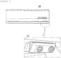
- FIG. 1 mounted in the vicinity of an air outlet of a wall mounting type air conditioner 20 additionally, there may a small sized modular ionizer 10 for generating at least one of anion and cation.
- the ionizer 10 may be mounted to a stand type air conditioner 30 in the vicinity of an air outlet thereof in a small sized modular mode for generating at least one of the anion and the cation.
- JP 2005 114195 A relates to an air conditioner according to the preamble of claim 1 including an ion generating device which is capable of uniformly distributing ions in a room, especially in the corners.
- the present invention has been made in an effort to solve the aforementioned problems, and it is an object of the present invention to provide an air conditioner which makes ions generated by an ionizer to diffuse effectively owing to an air flow.
- the present invention provides an air conditioner according to claim 1 including, among other features, an ionizer to generate ions mounted on a vicinity of an air outlet, a carrier to move the ionizer, and a controller to control the ionizer and the carrier.
- the air conditioner may further comprise a front chassis, and the ionizer is mounted on an inside of the front chassis.
- the carrier includes a step motor and a lead screw, and the ionizer may move interlocked with the lead screw when the motor rotates the lead screw.
- the step motor and the lead screw may be mounted on an inside of the air outlet.
- the controller may control the carrier to move the ionizer to an initial position when power is supplied to the air conditioner or the power is changed from turn off to turn on.
- the controller may control a position of the ionizer with a number of pulses applied to the step motor from the initial position.
- the air conditioner further includes a sensor to sense a position of a person, and the controller may control the position of the ionizer through the carrier in response to a sensing signal of the sensor.
- the senor may be one of an ultrasonic sensor, an infrared sensor, and a heat sensor.
- the senor may be mounted to a front of the air conditioner.
- the controller may determine a range a person presents with respect to the air conditioner with the sensor, and may control the carrier to make the ionizer to reciprocate within the range determined by the controller.
- the controller may control the ionizer to increase an ion generation rate when the ionizer passes the range the person presents with respect to the air conditioner.
- the controller may increase strength of air flow from the air conditioner when the ionizer passes the range the person presents with respect to the air conditioner.
- the air conditioner further comprises an input unit, wherein an operation mode among a plurality of operation modes are set through the input unit.
- the operation mode may be a water fall mode in which the controller controls an operation of the ionizer to set an ion generation rate to a highest, as well as move a position of the ionizer to a center of the air conditioner, to diffuse the ions at the center, and the controller sets an air flow rate of the air conditioner to be higher than other modes among the plurality of modes.
- the operation mode may be a sleeping mode in which the controller controls an operation of the ionizer to set an ion generation rate to a lowest, as well as move a position of the ionizer to a left side and a right side of the air conditioner alternately at predetermined time intervals, to spread the generated ions.
- the air conditioner further includes a vane driver to drive a vane which controls a direction of air being discharged
- the controller may control the carrier to reciprocate the ionizer periodically, controls the vane driver to swing the vane periodically, and synchronizes a reciprocating period of the ionizer and a swing period of the vane at a predetermined ratio to distribute ion concentration uniformly.
- the air conditioner further includes a vane driver to drive the vane which controls a direction of the air being discharged, and the controller may move the position of the ionizer taking a position the person presents with respect to the air conditioner determined by the controller with the sensor and the controller may take into account direction of the vane in a state the vane is set to swing.
- the controller when the vane rotates to direct the air to a right side, the controller may control the carrier to position the ionizer at a left side, and, when the vane rotates to direct the air to the left side, the controller may control the carrier to position the ionizer at the right side.
- the air conditioner in accordance with an embodiment of the present invention may have a movable ionizer mounted in the vicinity of an air outlet.
- the air conditioner of the present invention may include an ionizer for generating ions, and a carrier for moving the ionizer.
- the air conditioner is a machine for controlling a temperature, humidity, and an air quality of a space having an air cleaner, an air heater, an air cooler, a humidifier, a fan, and so on mounted therein.
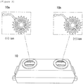
- the ionizer 10 may be in a small sized modular mode having an anion electrode 10a for generating an anion, and a cation electrode 10b for generating a cation.
- the modular ionizer 10 may be mounted in the vicinity of an outlet extended in a horizontal direction of the air conditioner, such that the modular ionizer 10 is movable along the air outlet in response to a signal, applied by a user, or from a human body sensor.
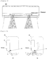
- the ionizer 10 may be mounted to a structure on an inside of a front chassis 21 for making the ionizer 10 invisible from an outside of the air conditioner 20, and making the anions to be discharged following an air flow of the air conditioner being discharged through the outlet.
- the ionizer 10 moves, for an example, along a rail 51 mounted in a horizontal direction, wherein the rail 51 may be a lead screw rotated by driving the motor 52.
- the lead screw has a helical groove (A thread) formed therein, and the ionizer 10 has link ring 10c with a needle or a rack formed therein to be engaged with the groove (Thread) in the lead screw, if the lead screw rotates, the ionizer 10 moves in a length direction of the rail.
- the motor 52 may be, for an example, a step motor for controlling rotation of a rotor in steps to control a position of a component connected to the lead screw accurately, wherein, as shown in FIG. 6 , a driving unit 53 which applies a voltage to the motor 52 is operated under the control of a controller 54, such as a microcomputer.
- the position of the ionizer 10 may be controlled with a number of pulses, i.e., a number of steps, applied to the step motor in a feed forward method, without using an additional position sensor.
- the controller 54 may move the position of the ionizer 10 to any position by controlling operation of the driving unit 53 in response to a signal applied by the user received through an input unit 55, or may move the position of the ionizer 10 to a position in the vicinity of a direction in which a human body is sensed by controlling operation of the driving unit 53 in response to a body sensed signal sensed by a sensor unit 56.
- the input unit 55 may include a remote controller receiver module or a key panel for making the driving unit 53 to perform an operation the user desires selectively
- the sensor unit 56 may include at least one of different types of human body sensors, such as an ultrasonic sensor, an infrared sensor, a heat sensor, and so on for automatic sensing of the position of the user.
- the human body sensor may be mounted to the front chassis 21 of the air conditioner, for an example, to a front of the air outlet for sensing the position of the user.
- the controller 54 controls operation of the driving unit 53 in response to the human body sensed signal, to make a position of the ionizer 10 to direct the user.
- the sensor unit 56 outputs the human body sensed signal corresponding to the movement of the user, and the controller 54 controls the operation of the driving unit 53, to control to vary the voltage to be applied to the motor 53.
- the position of the ionizer 10 is moved from the left side to the right side along the rail 51 which rotates as the motor 53 is driven, making the ions to emit from the ionizer 10 toward the user moved to the right side, an ion effect the user feels can be improved, effectively.
- the controller 54 controls operation of the driving unit 53 to make the position of the ionizer 10 to move in response to the signal applied by the user.
- the controller 54 sets a specific operation mode according to the signal applied by the user received through the input unit 55, wherein the specific operation mode may be any one of a plurality of operation modes set in advance for changing an ion generation rate, an air flow rate, or the like.
- the controller 54 controls the operation of the ionizer 10 to increase the ion generation rate to a highest, as well as move the position of the ionizer 10 to a center, to diffuse the ions at the center intensively.
- the air flow rate of the air conditioner may be increased compared to a prior operation mode.
- the controller 54 controls the operation of the ionizer 10 to reduce the ion generation rate to a lowest as well as make the position of the ionizer 10 to move to the left side and the right side alternately at predetermined time intervals, to spread the ions generated thus to the left side and the right side widely while the user sleeps.
- the controller 54 controls the operation of the driving unit 53 to move the position of the ionizer 10 to an initial point set in advance.
- the controller 54 may make precise control on the step motor by moving the ionizer 10 to the closest one of the initial points and initializing a value of the step count counted up to now.
- the controller 54 may control the driving unit 53 to move the ionizer 10 to one of the initial points when the power is supplied to the air conditioner or the power is changing from turn off to turn on.
- the controller 54 can determine the position of the ionizer 10 with the number of pulses, i.e., the number of steps, applied to the step motor through the driving unit 53 from the initial point.
- the air conditioner may include a vane for controlling a direction of the air being discharged, and a vane driver for driving the vane, and, in order to control a distribution of ion concentration of a room, the controller 54 may control the position of the ionizer 10 interlocked with the direction of the vane, or strength of the air being discharged by the air conditioner or the ion generation rate of the ionizer 10 interlocked with the position of the ionizer 10.
- the controller 54 may control the driving unit 53 to reciprocate the ionizer 10 periodically, and, additionally, to make the vane of the air conditioner to swing, to distribute the ions generated by the ionizer far and uniformly, wherein, by synchronizing a reciprocating period of the ionizer 10 and a swing period of the vane, in an one to one ratio, in an integer ratio, or in a rational number ratio, it may also be possible to make the vane to have angles different from one another every time the ionizer 10 passes respective positions within a reciprocating section.
- the controller 54 can grasp a range the user presents thereto from the human body sensed signal detected by the sensor unit 56 and control the driving unit 53 to make the ionizer 10 to reciprocate within the range grasped thus, or, in a state the ionizer 10 is set to reciprocate, control the ionizer 10 to increase the ion generation rate when the ionizer 10 passes the range, or control a fan (Not shown) which generates an air flow to increase a strength of the air flow or a flow rate of the air.
- the controller 54 can also move the position of the ionizer 10 taking the position of the user and the direction of the vane into account in a state the vane which controls a direction of the air being discharged from the air conditioner is set to swing, wherein it may be possible that the ions generated by the ionizer 10 can be focused on the user according to the air flow of which direction is controlled by the vane by making the ionizer 10 to position at a left side further than the user, if the vane rotates to direct the air being discharged to the right side, and by making the ionizer 10 to position at the right side further than the user, if the vane rotates to direct the air being discharged to the left side.
- the air conditioner with an ionizer of the present invention has the following advantage.
- a range of ion diffusion can be controlled more efficiently, an ion effect the user feels can be improved by making to discharge the ions to a direction the user presents thereto.
Landscapes
- Engineering & Computer Science (AREA)
- Chemical & Material Sciences (AREA)
- Combustion & Propulsion (AREA)
- Mechanical Engineering (AREA)
- General Engineering & Computer Science (AREA)
- Physics & Mathematics (AREA)
- Fluid Mechanics (AREA)
- Signal Processing (AREA)
- Health & Medical Sciences (AREA)
- Human Computer Interaction (AREA)
- Mathematical Physics (AREA)
- Fuzzy Systems (AREA)
- Epidemiology (AREA)
- Life Sciences & Earth Sciences (AREA)
- Animal Behavior & Ethology (AREA)
- General Health & Medical Sciences (AREA)
- Public Health (AREA)
- Veterinary Medicine (AREA)
- Air Conditioning Control Device (AREA)
- Disinfection, Sterilisation Or Deodorisation Of Air (AREA)
Description
- The present invention relates to an air conditioner with an ionizer, and more specifically the present invention relates to an air conditioner having a movable ionizer arranged in the vicinity of an air outlet.
- As environmental pollution becomes the worse, people having different respiratory disease or showing allergy reaction caused by polluted air increases the more. Consequently, various attempts, such as generation of anions, have been made for cleaning the polluted air to improve a quality of the air.
- Since the anion, a molecule of oxygen, nitrogen, or so on having a negative charge, is very beneficial for a human body, and effective for removal of dust and odor, an ionizer module is additionally mounted to, and used in, different types of domestic appliances, such as an air conditioner, or air cleaner.
- Referring to
FIG. 1 , as an example, mounted in the vicinity of an air outlet of a wall mountingtype air conditioner 20 additionally, there may a small sizedmodular ionizer 10 for generating at least one of anion and cation. - Referring to
FIG. 2 , theionizer 10 may be mounted to a standtype air conditioner 30 in the vicinity of an air outlet thereof in a small sized modular mode for generating at least one of the anion and the cation. - However, since the
ionizer 10 is mounted secured to a side, i.e., a left side or a right side, of the air outlet of the domestic appliance, such as the air cleaner or the air conditioner due to limitation of a mounting space, diffusion of the ions carried by air being discharged is limited, and, moreover, since the ions are discharged in a direction, not relevant to a position of a user, theionizer 10 has a problem in that the user fails to feel an effect of the anion, properly.JP 2005 114195 A - Accordingly, the present invention has been made in an effort to solve the aforementioned problems, and it is an object of the present invention to provide an air conditioner which makes ions generated by an ionizer to diffuse effectively owing to an air flow.
- It is another object of the present invention to provide an air conditioner which makes ions to be forwarded to a person in a room, effectively.
- The present invention provides an air conditioner according to claim 1 including, among other features, an ionizer to generate ions mounted on a vicinity of an air outlet, a carrier to move the ionizer, and a controller to control the ionizer and the carrier.
- In accordance with an embodiment of the present invention, the air conditioner may further comprise a front chassis, and the ionizer is mounted on an inside of the front chassis.
- In accordance with an embodiment of the present invention, the carrier includes a step motor and a lead screw, and the ionizer may move interlocked with the lead screw when the motor rotates the lead screw.
- In accordance with an embodiment of the present invention, the step motor and the lead screw may be mounted on an inside of the air outlet.
- In accordance with an embodiment of the present invention, the controller may control the carrier to move the ionizer to an initial position when power is supplied to the air conditioner or the power is changed from turn off to turn on.
- In accordance with an embodiment of the present invention, the controller may control a position of the ionizer with a number of pulses applied to the step motor from the initial position.
- In accordance with an embodiment of the present invention, the air conditioner further includes a sensor to sense a position of a person, and the controller may control the position of the ionizer through the carrier in response to a sensing signal of the sensor.
- In accordance with an embodiment of the present invention, the sensor may be one of an ultrasonic sensor, an infrared sensor, and a heat sensor.
- In accordance with an embodiment of the present invention, the sensor may be mounted to a front of the air conditioner.
- In accordance with an embodiment of the present invention, the controller may determine a range a person presents with respect to the air conditioner with the sensor, and may control the carrier to make the ionizer to reciprocate within the range determined by the controller.
- In accordance with an embodiment of the present invention, if the controller sets the ionizer to reciprocate, the controller may control the ionizer to increase an ion generation rate when the ionizer passes the range the person presents with respect to the air conditioner.
- In accordance with an embodiment of the present invention, if the controller sets the ionizer to reciprocate, the controller may increase strength of air flow from the air conditioner when the ionizer passes the range the person presents with respect to the air conditioner.
- In accordance with an embodiment of the present invention, the air conditioner further comprises an input unit, wherein an operation mode among a plurality of operation modes are set through the input unit.
- In accordance with an embodiment of the present invention, the operation mode may be a water fall mode in which the controller controls an operation of the ionizer to set an ion generation rate to a highest, as well as move a position of the ionizer to a center of the air conditioner, to diffuse the ions at the center, and the controller sets an air flow rate of the air conditioner to be higher than other modes among the plurality of modes.
- In accordance with an embodiment of the present invention, the operation mode may be a sleeping mode in which the controller controls an operation of the ionizer to set an ion generation rate to a lowest, as well as move a position of the ionizer to a left side and a right side of the air conditioner alternately at predetermined time intervals, to spread the generated ions.
- In accordance with an embodiment of the present invention, the air conditioner further includes a vane driver to drive a vane which controls a direction of air being discharged, and the controller may control the carrier to reciprocate the ionizer periodically, controls the vane driver to swing the vane periodically, and synchronizes a reciprocating period of the ionizer and a swing period of the vane at a predetermined ratio to distribute ion concentration uniformly.
- In accordance with an embodiment of the present invention, the air conditioner further includes a vane driver to drive the vane which controls a direction of the air being discharged, and the controller may move the position of the ionizer taking a position the person presents with respect to the air conditioner determined by the controller with the sensor and the controller may take into account direction of the vane in a state the vane is set to swing.
- In accordance with an embodiment of the present invention, when the vane rotates to direct the air to a right side, the controller may control the carrier to position the ionizer at a left side, and, when the vane rotates to direct the air to the left side, the controller may control the carrier to position the ionizer at the right side.
-
-
FIG. 1 is a front view illustrating a general wall mounting type air conditioner having an ionizer module mounted thereto; -
FIG. 2 is a front view illustrating a general stand type air conditioner having an ionizer module mounted thereto; -
FIG. 3 is a perspective view illustrating an ionizer applicable to the present invention; -
FIG. 4 is a front view illustrating an ionizer movable in a horizontal direction in an air conditioner in accordance with an embodiment of the present invention; -
FIGS. 5A and 5B are schematic views illustrating an ionizer mounted to an inside structure in the vicinity of an air outlet in an air conditioner in accordance with an embodiment of the present invention; -
FIG. 6 is a block diagram of an air conditioner in accordance with an embodiment of the present invention; -
FIG. 7 is a schematic view of an ionizer in an air conditioner in accordance with an embodiment of the present invention illustrating the ionizer moving toward a user. - In what follows, an ionizer according to preferred embodiments of the present invention will be described in detail with reference to the appended drawings.
- The air conditioner in accordance with an embodiment of the present invention may have a movable ionizer mounted in the vicinity of an air outlet. For an example, the air conditioner of the present invention may include an ionizer for generating ions, and a carrier for moving the ionizer. In the specification, the air conditioner is a machine for controlling a temperature, humidity, and an air quality of a space having an air cleaner, an air heater, an air cooler, a humidifier, a fan, and so on mounted therein.
- Referring to
FIG. 3 , theionizer 10 may be in a small sized modular mode having ananion electrode 10a for generating an anion, and acation electrode 10b for generating a cation. - And, referring to
FIG. 4 , themodular ionizer 10 may be mounted in the vicinity of an outlet extended in a horizontal direction of the air conditioner, such that themodular ionizer 10 is movable along the air outlet in response to a signal, applied by a user, or from a human body sensor. - And, referring to
FIG. 5 , if theionizer 10 is mounted to, for an example, to a wall mountingtype air conditioner 20, theionizer 10 may be mounted to a structure on an inside of afront chassis 21 for making theionizer 10 invisible from an outside of theair conditioner 20, and making the anions to be discharged following an air flow of the air conditioner being discharged through the outlet. - Referring to
FIG. 6 , theionizer 10 moves, for an example, along arail 51 mounted in a horizontal direction, wherein therail 51 may be a lead screw rotated by driving themotor 52. - And, referring to
FIG. 6 , since the lead screw has a helical groove (A thread) formed therein, and theionizer 10 haslink ring 10c with a needle or a rack formed therein to be engaged with the groove (Thread) in the lead screw, if the lead screw rotates, theionizer 10 moves in a length direction of the rail. - The
motor 52 may be, for an example, a step motor for controlling rotation of a rotor in steps to control a position of a component connected to the lead screw accurately, wherein, as shown inFIG. 6 , adriving unit 53 which applies a voltage to themotor 52 is operated under the control of acontroller 54, such as a microcomputer. The position of theionizer 10 may be controlled with a number of pulses, i.e., a number of steps, applied to the step motor in a feed forward method, without using an additional position sensor. - And, the
controller 54 may move the position of theionizer 10 to any position by controlling operation of thedriving unit 53 in response to a signal applied by the user received through aninput unit 55, or may move the position of theionizer 10 to a position in the vicinity of a direction in which a human body is sensed by controlling operation of thedriving unit 53 in response to a body sensed signal sensed by asensor unit 56. - For an example, the
input unit 55 may include a remote controller receiver module or a key panel for making thedriving unit 53 to perform an operation the user desires selectively, and thesensor unit 56 may include at least one of different types of human body sensors, such as an ultrasonic sensor, an infrared sensor, a heat sensor, and so on for automatic sensing of the position of the user. - And, referring to
FIG. 5 , the human body sensor may be mounted to thefront chassis 21 of the air conditioner, for an example, to a front of the air outlet for sensing the position of the user. - Referring to
FIG. 7 , upon reception of, for an example, the body sensed signal from thesensor unit 56, thecontroller 54 controls operation of thedriving unit 53 in response to the human body sensed signal, to make a position of theionizer 10 to direct the user. - For an example, if the user moves from a left side of the air conditioner to a right side thereof, the
sensor unit 56 outputs the human body sensed signal corresponding to the movement of the user, and thecontroller 54 controls the operation of thedriving unit 53, to control to vary the voltage to be applied to themotor 53. - According to this, the position of the
ionizer 10 is moved from the left side to the right side along therail 51 which rotates as themotor 53 is driven, making the ions to emit from theionizer 10 toward the user moved to the right side, an ion effect the user feels can be improved, effectively. - And, if the signal applied by the user received through the
input unit 55 is the remote controller signal corresponding to the position control on the ionizer, thecontroller 54 controls operation of thedriving unit 53 to make the position of theionizer 10 to move in response to the signal applied by the user. - The
controller 54 sets a specific operation mode according to the signal applied by the user received through theinput unit 55, wherein the specific operation mode may be any one of a plurality of operation modes set in advance for changing an ion generation rate, an air flow rate, or the like. - For example, if the specific mode is a water fall mode in which the ion generation rate is set to a highest, the
controller 54 controls the operation of theionizer 10 to increase the ion generation rate to a highest, as well as move the position of theionizer 10 to a center, to diffuse the ions at the center intensively. In this time, the air flow rate of the air conditioner may be increased compared to a prior operation mode. - Opposite to this, if the specific mode is, for an example, a sleeping mode in which the ion generation rate is set to a lowest, the
controller 54 controls the operation of theionizer 10 to reduce the ion generation rate to a lowest as well as make the position of theionizer 10 to move to the left side and the right side alternately at predetermined time intervals, to spread the ions generated thus to the left side and the right side widely while the user sleeps. - And, if a system power of the air conditioner is turned off, or an initializing operation is performed in response to the signal applied by the user, the
controller 54 controls the operation of thedriving unit 53 to move the position of theionizer 10 to an initial point set in advance. - For an example, the
controller 54 may make precise control on the step motor by moving theionizer 10 to the closest one of the initial points and initializing a value of the step count counted up to now. - In order to make the
controller 54 to be able to determine and control the position of theionizer 10 even after supply of the system power fails suddenly during operation of the air conditioner, thecontroller 54 may control thedriving unit 53 to move theionizer 10 to one of the initial points when the power is supplied to the air conditioner or the power is changing from turn off to turn on. Thecontroller 54 can determine the position of theionizer 10 with the number of pulses, i.e., the number of steps, applied to the step motor through thedriving unit 53 from the initial point. - In the meantime, the air conditioner may include a vane for controlling a direction of the air being discharged, and a vane driver for driving the vane, and, in order to control a distribution of ion concentration of a room, the
controller 54 may control the position of theionizer 10 interlocked with the direction of the vane, or strength of the air being discharged by the air conditioner or the ion generation rate of theionizer 10 interlocked with the position of theionizer 10. - If it is intended to distribute the concentration of the ions in the room uniformly, the
controller 54 may control the drivingunit 53 to reciprocate theionizer 10 periodically, and, additionally, to make the vane of the air conditioner to swing, to distribute the ions generated by the ionizer far and uniformly, wherein, by synchronizing a reciprocating period of theionizer 10 and a swing period of the vane, in an one to one ratio, in an integer ratio, or in a rational number ratio, it may also be possible to make the vane to have angles different from one another every time theionizer 10 passes respective positions within a reciprocating section. - The
controller 54 can grasp a range the user presents thereto from the human body sensed signal detected by thesensor unit 56 and control the drivingunit 53 to make theionizer 10 to reciprocate within the range grasped thus, or, in a state theionizer 10 is set to reciprocate, control theionizer 10 to increase the ion generation rate when theionizer 10 passes the range, or control a fan (Not shown) which generates an air flow to increase a strength of the air flow or a flow rate of the air. - Moreover, the
controller 54 can also move the position of theionizer 10 taking the position of the user and the direction of the vane into account in a state the vane which controls a direction of the air being discharged from the air conditioner is set to swing, wherein it may be possible that the ions generated by theionizer 10 can be focused on the user according to the air flow of which direction is controlled by the vane by making theionizer 10 to position at a left side further than the user, if the vane rotates to direct the air being discharged to the right side, and by making theionizer 10 to position at the right side further than the user, if the vane rotates to direct the air being discharged to the left side. - As has been described, the air conditioner with an ionizer of the present invention has the following advantage.
- A range of ion diffusion can be controlled more efficiently, an ion effect the user feels can be improved by making to discharge the ions to a direction the user presents thereto.
- While this invention has been described in connection with what is presently considered to be practical exemplary embodiments, it is to be understood that technical aspects of the present invention are not limited to the exemplary embodiments suggested in the specification, but, though a person of an ordinary skill in this field of art who understand the technical aspects of the present invention can suggest another exemplary embodiment by modifications, changes, removal, and addtion of constituent elements within a range of technical aspects the same with the present invention, it may also be within the scope of the present invention which is defined by the appended claims.
Claims (15)
- An air conditioner (20) comprising:an ionizer (10) to generate ions mounted on a vicinity of an air outlet;a carrier (51, 52) to move the ionizer;a vane driver (53) to drive a vane which controls a direction of air being discharged;an input unit (55) to set an operation mode among a plurality of operation modes; anda controller (54) to control a position of the ionizer through the carrier,characterized in thatthe air conditioner further comprises a sensor (56) to sense a position of a person; andthe controller is configured to control the position of the ionizer interlocked with a direction of the vane, strength of the air being discharged by the air conditioner, or an ion generation rate of the ionizer, or is configured to control the position of the ionizer according to a mode select signal inputted through the input unit.
- The air conditioner as claimed in claim 1, wherein the air conditioner further comprises a front chassis (21), and the ionizer is mounted on an inside of the front chassis.
- The air conditioner as claimed in claim 1 or 2, wherein the carrier includes a step motor (52) and a lead screw (51), and the ionizer moves interlocked with the lead screw when the motor rotates the lead screw.
- The air conditioner as claimed in claim 3, wherein the step motor and the lead screw are mounted on an inside of the air outlet.
- The air conditioner as claimed in claim 3 or 4, wherein the controller controls the step motor to move the ionizer to an initial position when power is supplied to the air conditioner or the power is changed from turn off to turn on.
- The air conditioner as claimed in claim 5, wherein the controller is configured to control a position of the ionizer with a number of pulses applied to the step motor from the initial position.
- The air conditioner as claimed in one of the preceding claims, wherein the sensor is one of an ultrasonic sensor, an infrared sensor, and a heat sensor.
- The air conditioner as claimed in claim 7, wherein the sensor is mounted to a front of the air conditioner.
- The air conditioner as claimed in any one of claims 7 or 8 wherein the controller is configured to determine a range a person presents with respect to the air conditioner with the sensor, and to control the carrier to make the ionizer to reciprocate within the range determined by the controller.
- The air conditioner as claimed in claim 9, wherein, if the controller sets the ionizer to reciprocate, the controller is configured to control the ionizer to increase an ion generation rate when the ionizer passes the range the person presents with respect to the air conditioner.
- The air conditioner as claimed in claim 9, wherein, if the controller sets the ionizer to reciprocate, the controller is configured to increase strength of air flow from the air conditioner when the ionizer passes the range the person presents with respect to the air conditioner.
- The air conditioner as claimed in any one of claims 7 to 11,
wherein the controller controls the carrier to reciprocate the ionizer periodically, controls the vane driver to swing the vane periodically, and synchronizes a reciprocating period of the ionizer and a swing period of the vane at a predetermined ratio to distribute ion concentration uniformly. - The air conditioner as claimed in any one of claims 7 to 11,
wherein the controller moves the position of the ionizer taking a position the person presents with respect to the air conditioner determined by the controller with the sensor and the controller takes into account direction of the vane in a state the vane is set to swing. - The air conditioner as claimed in claim 13, wherein, when the vane rotates to direct the air to a right side, the controller controls the carrier to position the ionizer at a left side, and, when the vane rotates to direct the air to the left side, the controller controls the carrier to position the ionizer at the right side.
- The air conditioner as claimed in one of the preceding claims, wherein the operation mode includes a water fall mode and a sleeping mode.
Applications Claiming Priority (1)
| Application Number | Priority Date | Filing Date | Title |
|---|---|---|---|
| KR1020120109094A KR101936749B1 (en) | 2012-09-28 | 2012-09-28 | Movable Ionizer |
Publications (3)
| Publication Number | Publication Date |
|---|---|
| EP2713114A2 EP2713114A2 (en) | 2014-04-02 |
| EP2713114A3 EP2713114A3 (en) | 2018-04-04 |
| EP2713114B1 true EP2713114B1 (en) | 2020-11-04 |
Family
ID=49274453
Family Applications (1)
| Application Number | Title | Priority Date | Filing Date |
|---|---|---|---|
| EP13186343.3A Not-in-force EP2713114B1 (en) | 2012-09-28 | 2013-09-27 | Air conditioner with ionizer |
Country Status (4)
| Country | Link |
|---|---|
| US (1) | US9453651B2 (en) |
| EP (1) | EP2713114B1 (en) |
| KR (1) | KR101936749B1 (en) |
| CN (1) | CN103712281B (en) |
Cited By (2)
| Publication number | Priority date | Publication date | Assignee | Title |
|---|---|---|---|---|
| CN111649404A (en) * | 2020-06-10 | 2020-09-11 | 东北大学 | A kind of internal airflow self-adjusting clean room and airflow adjustment method |
| EP4470919A3 (en) * | 2023-06-02 | 2025-01-22 | Goodrich Lighting Systems, Inc. | Next gen passenger service unit |
Families Citing this family (14)
| Publication number | Priority date | Publication date | Assignee | Title |
|---|---|---|---|---|
| JP6463657B2 (en) * | 2015-06-01 | 2019-02-06 | シャープ株式会社 | Air conditioner |
| CN106338105B (en) * | 2015-07-08 | 2020-04-10 | 松下知识产权经营株式会社 | Intake device and intake method |
| US10828646B2 (en) | 2016-07-18 | 2020-11-10 | Agentis Air Llc | Electrostatic air filter |
| CN106225144A (en) * | 2016-07-21 | 2016-12-14 | 广东美的制冷设备有限公司 | Air-conditioner and control method thereof |
| JP7084732B2 (en) * | 2018-01-25 | 2022-06-15 | 株式会社コロナ | Air conditioner |
| CN112312953A (en) * | 2018-06-15 | 2021-02-02 | H标记有限公司 | Multi-sensory and multimedia room |
| US10875034B2 (en) * | 2018-12-13 | 2020-12-29 | Agentis Air Llc | Electrostatic precipitator |
| US10792673B2 (en) | 2018-12-13 | 2020-10-06 | Agentis Air Llc | Electrostatic air cleaner |
| CN112747421B (en) * | 2019-10-31 | 2022-06-03 | 广东美的制冷设备有限公司 | Air conditioner, control method and device thereof, and computer readable storage medium |
| JP2021116947A (en) * | 2020-01-23 | 2021-08-10 | シャープ株式会社 | Indoor unit of air conditioner, server, control method, and control program |
| WO2021185814A1 (en) * | 2020-03-16 | 2021-09-23 | Philip Morris Products S.A. | Moveable ionization unit for cleaning air in a room with a support structure |
| KR102304210B1 (en) * | 2021-01-28 | 2021-09-23 | 황영선 | bed head having air cleaning function |
| KR102611258B1 (en) * | 2022-02-04 | 2023-12-07 | (주)제이엔텍 | Air sterilization system |
| CN119901014B (en) * | 2023-10-20 | 2025-12-09 | 宁波奥克斯电气有限公司 | Ion wind air conditioner assembly capable of evenly discharging wind |
Family Cites Families (12)
| Publication number | Priority date | Publication date | Assignee | Title |
|---|---|---|---|---|
| GB2260830B (en) * | 1991-10-24 | 1994-10-19 | Norm Pacific Automat Corp | Ventilation device adjusted and controlled automatically with movement of human body |
| JP3960812B2 (en) | 2002-02-06 | 2007-08-15 | シャープ株式会社 | Air conditioner |
| JP2003336871A (en) | 2002-05-16 | 2003-11-28 | Sharp Corp | Air cleaner |
| JP2004347264A (en) | 2003-05-23 | 2004-12-09 | Sharp Corp | Blower, louver, and air conditioner provided with the same |
| JP2005114195A (en) * | 2003-10-03 | 2005-04-28 | Sharp Corp | Air conditioner with ion generator |
| JP2005156027A (en) | 2003-11-26 | 2005-06-16 | Sharp Corp | Air conditioner, fan heater, and method of deactivating antigenic substance |
| JP2006125803A (en) | 2004-11-01 | 2006-05-18 | Matsushita Electric Ind Co Ltd | Air conditioner |
| JP4382860B1 (en) | 2008-07-02 | 2009-12-16 | シャープ株式会社 | Air conditioner |
| JP4551953B2 (en) | 2008-08-28 | 2010-09-29 | シャープ株式会社 | Ion diffusion device |
| KR101591890B1 (en) | 2008-12-03 | 2016-02-04 | 엘지전자 주식회사 | Air conditioner |
| CN201488140U (en) | 2009-08-22 | 2010-05-26 | 海尔集团公司 | An IFP air conditioner |
| WO2011045979A1 (en) * | 2009-10-17 | 2011-04-21 | 株式会社千石 | Compact air purifying device equipped with ion generation means capable of changing blowing direction |
-
2012
- 2012-09-28 KR KR1020120109094A patent/KR101936749B1/en not_active Expired - Fee Related
-
2013
- 2013-09-16 US US14/027,497 patent/US9453651B2/en not_active Expired - Fee Related
- 2013-09-27 EP EP13186343.3A patent/EP2713114B1/en not_active Not-in-force
- 2013-09-29 CN CN201310455260.3A patent/CN103712281B/en not_active Expired - Fee Related
Non-Patent Citations (1)
| Title |
|---|
| None * |
Cited By (2)
| Publication number | Priority date | Publication date | Assignee | Title |
|---|---|---|---|---|
| CN111649404A (en) * | 2020-06-10 | 2020-09-11 | 东北大学 | A kind of internal airflow self-adjusting clean room and airflow adjustment method |
| EP4470919A3 (en) * | 2023-06-02 | 2025-01-22 | Goodrich Lighting Systems, Inc. | Next gen passenger service unit |
Also Published As
| Publication number | Publication date |
|---|---|
| KR101936749B1 (en) | 2019-01-10 |
| EP2713114A3 (en) | 2018-04-04 |
| US9453651B2 (en) | 2016-09-27 |
| EP2713114A2 (en) | 2014-04-02 |
| CN103712281A (en) | 2014-04-09 |
| US20140094108A1 (en) | 2014-04-03 |
| KR20140042974A (en) | 2014-04-08 |
| CN103712281B (en) | 2017-04-12 |
Similar Documents
| Publication | Publication Date | Title |
|---|---|---|
| US9453651B2 (en) | Air conditioner with ionizer | |
| CN105020839B (en) | The control method and air conditioner of wind guiding mechanism | |
| US7789951B2 (en) | Method and system for moving air purifier | |
| US20180100667A1 (en) | Air blower and air blowing system | |
| EP2292987A1 (en) | Air conditioner | |
| KR20190052703A (en) | Flavor aspirator | |
| US20170165387A1 (en) | Sanitizer | |
| US20230139744A1 (en) | Electronic vaporizer | |
| JP2018175113A (en) | Air cleaning device | |
| CN106225144A (en) | Air-conditioner and control method thereof | |
| JP2014238230A (en) | Blower | |
| US7434353B2 (en) | Electric blind | |
| KR20230061308A (en) | An apparatus and method for controlling an operation of an air conditioner | |
| CN110075327A (en) | The control method of disinfection cabinet and disinfection cabinet | |
| US20210145690A1 (en) | Sensing control method and apparatus | |
| KR101862204B1 (en) | Ion generator of car air conditioning system and control method using the same | |
| CN107560103B (en) | Air conditioner with purification function and control method thereof | |
| CN107420982A (en) | Air conditioner room unit and its control method with purification function | |
| CN108522487B (en) | Mite removing instrument, control system and control method thereof and mite removing method | |
| CA3125853C (en) | Convection oven | |
| JP2005249243A (en) | Air conditioning system | |
| KR20140054689A (en) | Apparatus for control of air conditioner and method thereof | |
| KR100789711B1 (en) | Control method of air cleaner | |
| KR20070014774A (en) | Aroma generating apparatus of air-conditioner and its operating method | |
| JP2017116255A (en) | Blower |
Legal Events
| Date | Code | Title | Description |
|---|---|---|---|
| PUAI | Public reference made under article 153(3) epc to a published international application that has entered the european phase |
Free format text: ORIGINAL CODE: 0009012 |
|
| 17P | Request for examination filed |
Effective date: 20131023 |
|
| AK | Designated contracting states |
Kind code of ref document: A2 Designated state(s): AL AT BE BG CH CY CZ DE DK EE ES FI FR GB GR HR HU IE IS IT LI LT LU LV MC MK MT NL NO PL PT RO RS SE SI SK SM TR |
|
| AX | Request for extension of the european patent |
Extension state: BA ME |
|
| RAP1 | Party data changed (applicant data changed or rights of an application transferred) |
Owner name: LG ELECTRONICS INC. |
|
| PUAL | Search report despatched |
Free format text: ORIGINAL CODE: 0009013 |
|
| AK | Designated contracting states |
Kind code of ref document: A3 Designated state(s): AL AT BE BG CH CY CZ DE DK EE ES FI FR GB GR HR HU IE IS IT LI LT LU LV MC MK MT NL NO PL PT RO RS SE SI SK SM TR |
|
| AX | Request for extension of the european patent |
Extension state: BA ME |
|
| RIC1 | Information provided on ipc code assigned before grant |
Ipc: F24F 3/16 20060101AFI20180301BHEP Ipc: F24F 1/00 20110101ALI20180301BHEP |
|
| RBV | Designated contracting states (corrected) |
Designated state(s): AL AT BE BG CH CY CZ DE DK EE ES FI FR GB GR HR HU IE IS IT LI LT LU LV MC MK MT NL NO PL PT RO RS SE SI SK SM TR |
|
| GRAP | Despatch of communication of intention to grant a patent |
Free format text: ORIGINAL CODE: EPIDOSNIGR1 |
|
| STAA | Information on the status of an ep patent application or granted ep patent |
Free format text: STATUS: GRANT OF PATENT IS INTENDED |
|
| RIC1 | Information provided on ipc code assigned before grant |
Ipc: F24F 1/00 20190101ALI20200407BHEP Ipc: F24F 3/16 20060101AFI20200407BHEP Ipc: F24F 120/12 20180101ALI20200407BHEP Ipc: F24F 11/89 20180101ALI20200407BHEP Ipc: F24F 11/30 20180101ALI20200407BHEP Ipc: F24F 1/0007 20190101ALI20200407BHEP Ipc: F24F 11/74 20180101ALI20200407BHEP Ipc: F24F 11/79 20180101ALI20200407BHEP |
|
| INTG | Intention to grant announced |
Effective date: 20200423 |
|
| GRAJ | Information related to disapproval of communication of intention to grant by the applicant or resumption of examination proceedings by the epo deleted |
Free format text: ORIGINAL CODE: EPIDOSDIGR1 |
|
| STAA | Information on the status of an ep patent application or granted ep patent |
Free format text: STATUS: REQUEST FOR EXAMINATION WAS MADE |
|
| GRAR | Information related to intention to grant a patent recorded |
Free format text: ORIGINAL CODE: EPIDOSNIGR71 |
|
| GRAS | Grant fee paid |
Free format text: ORIGINAL CODE: EPIDOSNIGR3 |
|
| STAA | Information on the status of an ep patent application or granted ep patent |
Free format text: STATUS: GRANT OF PATENT IS INTENDED |
|
| INTC | Intention to grant announced (deleted) | ||
| GRAA | (expected) grant |
Free format text: ORIGINAL CODE: 0009210 |
|
| STAA | Information on the status of an ep patent application or granted ep patent |
Free format text: STATUS: THE PATENT HAS BEEN GRANTED |
|
| INTG | Intention to grant announced |
Effective date: 20200916 |
|
| AK | Designated contracting states |
Kind code of ref document: B1 Designated state(s): AL AT BE BG CH CY CZ DE DK EE ES FI FR GB GR HR HU IE IS IT LI LT LU LV MC MK MT NL NO PL PT RO RS SE SI SK SM TR |
|
| REG | Reference to a national code |
Ref country code: GB Ref legal event code: FG4D |
|
| REG | Reference to a national code |
Ref country code: CH Ref legal event code: EP |
|
| REG | Reference to a national code |
Ref country code: AT Ref legal event code: REF Ref document number: 1331336 Country of ref document: AT Kind code of ref document: T Effective date: 20201115 |
|
| REG | Reference to a national code |
Ref country code: IE Ref legal event code: FG4D |
|
| REG | Reference to a national code |
Ref country code: DE Ref legal event code: R096 Ref document number: 602013073756 Country of ref document: DE |
|
| REG | Reference to a national code |
Ref country code: DE Ref legal event code: R079 Ref document number: 602013073756 Country of ref document: DE Free format text: PREVIOUS MAIN CLASS: F24F0003160000 Ipc: F24F0008000000 |
|
| REG | Reference to a national code |
Ref country code: NL Ref legal event code: MP Effective date: 20201104 |
|
| REG | Reference to a national code |
Ref country code: AT Ref legal event code: MK05 Ref document number: 1331336 Country of ref document: AT Kind code of ref document: T Effective date: 20201104 |
|
| PG25 | Lapsed in a contracting state [announced via postgrant information from national office to epo] |
Ref country code: GR Free format text: LAPSE BECAUSE OF FAILURE TO SUBMIT A TRANSLATION OF THE DESCRIPTION OR TO PAY THE FEE WITHIN THE PRESCRIBED TIME-LIMIT Effective date: 20210205 Ref country code: NO Free format text: LAPSE BECAUSE OF FAILURE TO SUBMIT A TRANSLATION OF THE DESCRIPTION OR TO PAY THE FEE WITHIN THE PRESCRIBED TIME-LIMIT Effective date: 20210204 Ref country code: PT Free format text: LAPSE BECAUSE OF FAILURE TO SUBMIT A TRANSLATION OF THE DESCRIPTION OR TO PAY THE FEE WITHIN THE PRESCRIBED TIME-LIMIT Effective date: 20210304 Ref country code: RS Free format text: LAPSE BECAUSE OF FAILURE TO SUBMIT A TRANSLATION OF THE DESCRIPTION OR TO PAY THE FEE WITHIN THE PRESCRIBED TIME-LIMIT Effective date: 20201104 Ref country code: FI Free format text: LAPSE BECAUSE OF FAILURE TO SUBMIT A TRANSLATION OF THE DESCRIPTION OR TO PAY THE FEE WITHIN THE PRESCRIBED TIME-LIMIT Effective date: 20201104 |
|
| PG25 | Lapsed in a contracting state [announced via postgrant information from national office to epo] |
Ref country code: ES Free format text: LAPSE BECAUSE OF FAILURE TO SUBMIT A TRANSLATION OF THE DESCRIPTION OR TO PAY THE FEE WITHIN THE PRESCRIBED TIME-LIMIT Effective date: 20201104 Ref country code: AT Free format text: LAPSE BECAUSE OF FAILURE TO SUBMIT A TRANSLATION OF THE DESCRIPTION OR TO PAY THE FEE WITHIN THE PRESCRIBED TIME-LIMIT Effective date: 20201104 Ref country code: BG Free format text: LAPSE BECAUSE OF FAILURE TO SUBMIT A TRANSLATION OF THE DESCRIPTION OR TO PAY THE FEE WITHIN THE PRESCRIBED TIME-LIMIT Effective date: 20210204 Ref country code: IS Free format text: LAPSE BECAUSE OF FAILURE TO SUBMIT A TRANSLATION OF THE DESCRIPTION OR TO PAY THE FEE WITHIN THE PRESCRIBED TIME-LIMIT Effective date: 20210304 Ref country code: PL Free format text: LAPSE BECAUSE OF FAILURE TO SUBMIT A TRANSLATION OF THE DESCRIPTION OR TO PAY THE FEE WITHIN THE PRESCRIBED TIME-LIMIT Effective date: 20201104 Ref country code: SE Free format text: LAPSE BECAUSE OF FAILURE TO SUBMIT A TRANSLATION OF THE DESCRIPTION OR TO PAY THE FEE WITHIN THE PRESCRIBED TIME-LIMIT Effective date: 20201104 Ref country code: LV Free format text: LAPSE BECAUSE OF FAILURE TO SUBMIT A TRANSLATION OF THE DESCRIPTION OR TO PAY THE FEE WITHIN THE PRESCRIBED TIME-LIMIT Effective date: 20201104 |
|
| REG | Reference to a national code |
Ref country code: LT Ref legal event code: MG9D |
|
| PG25 | Lapsed in a contracting state [announced via postgrant information from national office to epo] |
Ref country code: HR Free format text: LAPSE BECAUSE OF FAILURE TO SUBMIT A TRANSLATION OF THE DESCRIPTION OR TO PAY THE FEE WITHIN THE PRESCRIBED TIME-LIMIT Effective date: 20201104 |
|
| PG25 | Lapsed in a contracting state [announced via postgrant information from national office to epo] |
Ref country code: CZ Free format text: LAPSE BECAUSE OF FAILURE TO SUBMIT A TRANSLATION OF THE DESCRIPTION OR TO PAY THE FEE WITHIN THE PRESCRIBED TIME-LIMIT Effective date: 20201104 Ref country code: EE Free format text: LAPSE BECAUSE OF FAILURE TO SUBMIT A TRANSLATION OF THE DESCRIPTION OR TO PAY THE FEE WITHIN THE PRESCRIBED TIME-LIMIT Effective date: 20201104 Ref country code: SM Free format text: LAPSE BECAUSE OF FAILURE TO SUBMIT A TRANSLATION OF THE DESCRIPTION OR TO PAY THE FEE WITHIN THE PRESCRIBED TIME-LIMIT Effective date: 20201104 Ref country code: SK Free format text: LAPSE BECAUSE OF FAILURE TO SUBMIT A TRANSLATION OF THE DESCRIPTION OR TO PAY THE FEE WITHIN THE PRESCRIBED TIME-LIMIT Effective date: 20201104 Ref country code: RO Free format text: LAPSE BECAUSE OF FAILURE TO SUBMIT A TRANSLATION OF THE DESCRIPTION OR TO PAY THE FEE WITHIN THE PRESCRIBED TIME-LIMIT Effective date: 20201104 Ref country code: LT Free format text: LAPSE BECAUSE OF FAILURE TO SUBMIT A TRANSLATION OF THE DESCRIPTION OR TO PAY THE FEE WITHIN THE PRESCRIBED TIME-LIMIT Effective date: 20201104 |
|
| REG | Reference to a national code |
Ref country code: DE Ref legal event code: R097 Ref document number: 602013073756 Country of ref document: DE |
|
| PG25 | Lapsed in a contracting state [announced via postgrant information from national office to epo] |
Ref country code: DK Free format text: LAPSE BECAUSE OF FAILURE TO SUBMIT A TRANSLATION OF THE DESCRIPTION OR TO PAY THE FEE WITHIN THE PRESCRIBED TIME-LIMIT Effective date: 20201104 |
|
| PLBE | No opposition filed within time limit |
Free format text: ORIGINAL CODE: 0009261 |
|
| STAA | Information on the status of an ep patent application or granted ep patent |
Free format text: STATUS: NO OPPOSITION FILED WITHIN TIME LIMIT |
|
| 26N | No opposition filed |
Effective date: 20210805 |
|
| PG25 | Lapsed in a contracting state [announced via postgrant information from national office to epo] |
Ref country code: NL Free format text: LAPSE BECAUSE OF FAILURE TO SUBMIT A TRANSLATION OF THE DESCRIPTION OR TO PAY THE FEE WITHIN THE PRESCRIBED TIME-LIMIT Effective date: 20201104 Ref country code: IT Free format text: LAPSE BECAUSE OF FAILURE TO SUBMIT A TRANSLATION OF THE DESCRIPTION OR TO PAY THE FEE WITHIN THE PRESCRIBED TIME-LIMIT Effective date: 20201104 Ref country code: AL Free format text: LAPSE BECAUSE OF FAILURE TO SUBMIT A TRANSLATION OF THE DESCRIPTION OR TO PAY THE FEE WITHIN THE PRESCRIBED TIME-LIMIT Effective date: 20201104 |
|
| PG25 | Lapsed in a contracting state [announced via postgrant information from national office to epo] |
Ref country code: SI Free format text: LAPSE BECAUSE OF FAILURE TO SUBMIT A TRANSLATION OF THE DESCRIPTION OR TO PAY THE FEE WITHIN THE PRESCRIBED TIME-LIMIT Effective date: 20201104 |
|
| REG | Reference to a national code |
Ref country code: CH Ref legal event code: PL |
|
| REG | Reference to a national code |
Ref country code: BE Ref legal event code: MM Effective date: 20210930 |
|
| GBPC | Gb: european patent ceased through non-payment of renewal fee |
Effective date: 20210927 |
|
| PG25 | Lapsed in a contracting state [announced via postgrant information from national office to epo] |
Ref country code: IS Free format text: LAPSE BECAUSE OF FAILURE TO SUBMIT A TRANSLATION OF THE DESCRIPTION OR TO PAY THE FEE WITHIN THE PRESCRIBED TIME-LIMIT Effective date: 20210304 Ref country code: MC Free format text: LAPSE BECAUSE OF FAILURE TO SUBMIT A TRANSLATION OF THE DESCRIPTION OR TO PAY THE FEE WITHIN THE PRESCRIBED TIME-LIMIT Effective date: 20201104 |
|
| PG25 | Lapsed in a contracting state [announced via postgrant information from national office to epo] |
Ref country code: LU Free format text: LAPSE BECAUSE OF NON-PAYMENT OF DUE FEES Effective date: 20210927 Ref country code: IE Free format text: LAPSE BECAUSE OF NON-PAYMENT OF DUE FEES Effective date: 20210927 Ref country code: GB Free format text: LAPSE BECAUSE OF NON-PAYMENT OF DUE FEES Effective date: 20210927 Ref country code: BE Free format text: LAPSE BECAUSE OF NON-PAYMENT OF DUE FEES Effective date: 20210930 Ref country code: FR Free format text: LAPSE BECAUSE OF NON-PAYMENT OF DUE FEES Effective date: 20210930 |
|
| PG25 | Lapsed in a contracting state [announced via postgrant information from national office to epo] |
Ref country code: LI Free format text: LAPSE BECAUSE OF NON-PAYMENT OF DUE FEES Effective date: 20210930 Ref country code: CH Free format text: LAPSE BECAUSE OF NON-PAYMENT OF DUE FEES Effective date: 20210930 |
|
| PGFP | Annual fee paid to national office [announced via postgrant information from national office to epo] |
Ref country code: DE Payment date: 20220615 Year of fee payment: 10 |
|
| PG25 | Lapsed in a contracting state [announced via postgrant information from national office to epo] |
Ref country code: HU Free format text: LAPSE BECAUSE OF FAILURE TO SUBMIT A TRANSLATION OF THE DESCRIPTION OR TO PAY THE FEE WITHIN THE PRESCRIBED TIME-LIMIT; INVALID AB INITIO Effective date: 20130927 |
|
| PG25 | Lapsed in a contracting state [announced via postgrant information from national office to epo] |
Ref country code: CY Free format text: LAPSE BECAUSE OF FAILURE TO SUBMIT A TRANSLATION OF THE DESCRIPTION OR TO PAY THE FEE WITHIN THE PRESCRIBED TIME-LIMIT Effective date: 20201104 |
|
| REG | Reference to a national code |
Ref country code: DE Ref legal event code: R119 Ref document number: 602013073756 Country of ref document: DE |
|
| PG25 | Lapsed in a contracting state [announced via postgrant information from national office to epo] |
Ref country code: MK Free format text: LAPSE BECAUSE OF FAILURE TO SUBMIT A TRANSLATION OF THE DESCRIPTION OR TO PAY THE FEE WITHIN THE PRESCRIBED TIME-LIMIT Effective date: 20201104 |
|
| PG25 | Lapsed in a contracting state [announced via postgrant information from national office to epo] |
Ref country code: DE Free format text: LAPSE BECAUSE OF NON-PAYMENT OF DUE FEES Effective date: 20240403 |
|
| PG25 | Lapsed in a contracting state [announced via postgrant information from national office to epo] |
Ref country code: MT Free format text: LAPSE BECAUSE OF FAILURE TO SUBMIT A TRANSLATION OF THE DESCRIPTION OR TO PAY THE FEE WITHIN THE PRESCRIBED TIME-LIMIT Effective date: 20201104 |
|
| PG25 | Lapsed in a contracting state [announced via postgrant information from national office to epo] |
Ref country code: TR Free format text: LAPSE BECAUSE OF FAILURE TO SUBMIT A TRANSLATION OF THE DESCRIPTION OR TO PAY THE FEE WITHIN THE PRESCRIBED TIME-LIMIT Effective date: 20201104 |