EP2713016A2 - Exhaust diffuser arrangement for a turbine system and method of redirecting a flow - Google Patents
Exhaust diffuser arrangement for a turbine system and method of redirecting a flow Download PDFInfo
- Publication number
- EP2713016A2 EP2713016A2 EP13186831.7A EP13186831A EP2713016A2 EP 2713016 A2 EP2713016 A2 EP 2713016A2 EP 13186831 A EP13186831 A EP 13186831A EP 2713016 A2 EP2713016 A2 EP 2713016A2
- Authority
- EP
- European Patent Office
- Prior art keywords
- flow
- wall
- exhaust diffuser
- redirecting
- diffuser arrangement
- Prior art date
- Legal status (The legal status is an assumption and is not a legal conclusion. Google has not performed a legal analysis and makes no representation as to the accuracy of the status listed.)
- Granted
Links
- 238000000034 method Methods 0.000 title claims description 13
- 238000000926 separation method Methods 0.000 description 6
- 230000008901 benefit Effects 0.000 description 4
- 238000010586 diagram Methods 0.000 description 2
- 238000011144 upstream manufacturing Methods 0.000 description 2
- 230000004075 alteration Effects 0.000 description 1
- 230000004323 axial length Effects 0.000 description 1
- 238000012512 characterization method Methods 0.000 description 1
- 239000012530 fluid Substances 0.000 description 1
- 238000012423 maintenance Methods 0.000 description 1
- 238000006467 substitution reaction Methods 0.000 description 1
- 230000007704 transition Effects 0.000 description 1
Images

Classifications
-
- F—MECHANICAL ENGINEERING; LIGHTING; HEATING; WEAPONS; BLASTING
- F01—MACHINES OR ENGINES IN GENERAL; ENGINE PLANTS IN GENERAL; STEAM ENGINES
- F01D—NON-POSITIVE DISPLACEMENT MACHINES OR ENGINES, e.g. STEAM TURBINES
- F01D25/00—Component parts, details, or accessories, not provided for in, or of interest apart from, other groups
- F01D25/30—Exhaust heads, chambers, or the like
-
- F—MECHANICAL ENGINEERING; LIGHTING; HEATING; WEAPONS; BLASTING
- F05—INDEXING SCHEMES RELATING TO ENGINES OR PUMPS IN VARIOUS SUBCLASSES OF CLASSES F01-F04
- F05D—INDEXING SCHEME FOR ASPECTS RELATING TO NON-POSITIVE-DISPLACEMENT MACHINES OR ENGINES, GAS-TURBINES OR JET-PROPULSION PLANTS
- F05D2240/00—Components
- F05D2240/10—Stators
- F05D2240/12—Fluid guiding means, e.g. vanes
Definitions
- the subject matter disclosed herein relates to turbine systems, and more particularly to an exhaust diffuser for such turbines systems, as well as a method of redirecting a flow within the exhaust diffuser.
- an exhaust diffuser arrangement for a turbine system includes a diffuser duct having an inlet for receiving a flow in a first flow direction and an outlet configured to expel the flow in a second flow direction. Also included is a flow redirecting component disposed within the diffuser duct.
- the flow redirecting component includes a first end proximate the inlet, the first end comprising an opening for receiving the flow.
- the flow redirecting component also includes a first wall extending from the first end to a second end.
- the flow redirecting component further includes a second wall spaced downstream from the first wall and extending from the first end to the second end, the first wall and the second wall operably coupled at the second end, wherein the second wall includes at least one flow exit.
- a flow redirecting component 30 is disposed within the diffuser duct 20.
- the flow redirecting component 30 includes a first wall 32 having a first side 34 and a second side 36.
- the first side 34 is upstream of the second side 36 and is shaped to facilitate rapid redirecting of the flow 16.
- the shape of the first side 34 may be referred to as having a relatively concave surface geometry.
- the second side 36 of the first wall 32 is of a generally convex surface geometry.
- a second wall 38 is positioned in close proximity to the first wall 32 and is disposed at a downstream location relative to the first wall 32.
- the exhaust diffuser arrangement 10 may include a plurality of flow redirecting components. Irrespective of the number of flow redirecting components, the flow redirecting component 30 may be disposed at numerous locations within the diffuser duct 20, with the first end 40 typically being in close proximity to the inlet 12. Irrespective of the precise location of the flow redirecting component 30 within the diffuser duct 20, at least one strut 56 may be employed to secure the flow redirecting component 30.
- the at least one strut 56 is operably coupled to, or integrally formed with, the flow redirecting component 30 and at least one of the radially inner wall portion 22 and the radially outer wall portion 24. It is contemplated that a plurality of struts may be included to provide added structural integrity, with the precise number depending on the application of use.
- the at least one strut 56 may be of varying cross-sections, including circular.
- the flow redirecting component 30 assists in rapidly transitioning the flow 16 from the first flow direction 18 to the second flow direction 26.
- the first side 34 of the first wall 32 facilitates turning of the flow 16.
- the second wall 38, and the cavity 46 formed between the first wall 32 and the second wall 38 reduces flow separation at regions proximate the second side 36 of the first wall 32 by energizing a boundary layer present along the second side 36.
- reduction of flow separation proximate the second side 36 of the first wall 32 may be achieved by incorporating one or more suction components to energize the boundary layer.
- the effective rapid turning of the flow 16 allows for reduction of the overall exhaust diffuser arrangement 10 axial length.
Landscapes
- Engineering & Computer Science (AREA)
- Mechanical Engineering (AREA)
- General Engineering & Computer Science (AREA)
- Supercharger (AREA)
- Turbine Rotor Nozzle Sealing (AREA)
Abstract
Description
- The subject matter disclosed herein relates to turbine systems, and more particularly to an exhaust diffuser for such turbines systems, as well as a method of redirecting a flow within the exhaust diffuser.
- Turbine systems often include an exhaust diffuser that reduces the speed of a flow within the turbine system prior to expelling the flow into the atmosphere or another turbine system component and to recover pressure therein. In an effort to reduce the axial dimension of the turbine system, aggressive exhaust diffuser designs have been implemented with a high turn angle that the flow is routed through.
- One consequence of a high turn angle for the exhaust diffuser is flow separation proximate at least a portion of a casing wall that defines a duct through which the flow travels, thereby hindering the ability of the exhaust diffuser to reduce the speed of the flow and recover pressure within the duct prior to expulsion. In an effort to overcome the issues related to the high turn angle, while still reducing the axial dimension of the exhaust diffuser, structures such as guide vanes have been introduced into the duct of the exhaust diffuser to more rapidly redirect the flow with an upstream surface, however, flow separation proximate the downstream surface of the structure is typically exhibited, leading to issues similar to those discussed above with respect to flow separation proximate the casing.
- According to one aspect of the invention, an exhaust diffuser arrangement for a turbine system includes an inlet for receiving a flow proximate a last stage bucket of the turbine system, the flow flowing in a first flow direction. Also included is a flow redirecting component. The flow redirecting component includes a first wall having a first side of a concave surface geometry for redirecting the flow and a second side of a convex surface geometry. The flow redirecting component also includes a second wall spaced downstream of the first wall and having at least one flow exit for reducing a boundary layer along the second side of the first wall.
- According to another aspect of the invention, an exhaust diffuser arrangement for a turbine system includes a diffuser duct having an inlet for receiving a flow in a first flow direction and an outlet configured to expel the flow in a second flow direction. Also included is a flow redirecting component disposed within the diffuser duct. The flow redirecting component includes a first end proximate the inlet, the first end comprising an opening for receiving the flow. The flow redirecting component also includes a first wall extending from the first end to a second end. The flow redirecting component further includes a second wall spaced downstream from the first wall and extending from the first end to the second end, the first wall and the second wall operably coupled at the second end, wherein the second wall includes at least one flow exit.
- According to yet another aspect of the invention, a method of redirecting a flow within an exhaust diffuser is provided. The method includes routing a flow in a first flow direction to an inlet of the exhaust diffuser. Also included is redirecting the flow along a first side of a first wall of a flow redirecting component. Further included is injecting a portion of the flow into a cavity defined by the first wall and a second wall spaced downstream of the first wall. Yet further included is expelling the portion of the flow through at least one flow exit formed in the second wall, thereby reducing a boundary layer along a second side of the first wall.
- These and other advantages and features will become more apparent from the following description taken in conjunction with the drawings.
- The subject matter, which is regarded as the invention, is particularly pointed out and distinctly claimed in the claims at the conclusion of the specification. The foregoing and other features and advantages of the invention are apparent from the following detailed description taken in conjunction with the accompanying drawings in which:
-
FIG. 1 is an elevational side view of an exhaust diffuser arrangement having a flow redirecting component for a turbine system; -
FIG. 2 is a perspective view of the flow redirecting component within the exhaust diffuser arrangement; -
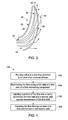
FIG. 3 is a side, cross-sectional view of the flow redirecting component; and -
FIG. 4 is a flow diagram illustrating a method of redirecting a flow within the exhaust diffuser arrangement. - The detailed description explains embodiments of the invention, together with advantages and features, by way of example with reference to the drawings.
- Referring to
FIGS. 1-3 , an exhaust diffuser arrangement is illustrated and generally referred to withnumeral 10. Theexhaust diffuser arrangement 10 may be employed in a variety of applications, such as a variety of turbine systems (not illustrated). Applications contemplated include axial or radial exhaust diffusers for a gas turbine system, as well as a steam turbine application, such as a low pressure split flow steam turbine, but it is to be appreciated that any exhaust system may benefit from implementation of theexhaust diffuser arrangement 10 described herein. - The
exhaust diffuser arrangement 10 includes aninlet 12 that is located proximate alast stage bucket 14 for receiving aflow 16 of fluid traveling at a relatively high velocity in a first flow direction 18, such as a predominantly axial direction, however, it is to be understood that the characterization of an axial direction of flow is merely illustrative and not limiting of the direction of travel of theflow 16. Theexhaust diffuser arrangement 10 includes adiffuser duct 20 that may be formed of various cross-sectional geometries and is defined by at least one casing wall that includes a radiallyinner wall portion 22 and a radiallyouter wall portion 24. Irrespective of the precise cross-sectional geometry of thediffuser duct 20, thediffuser duct 20 is shaped to rapidly transition theflow 16 from the first flow direction 18 to a second flow direction 26 toward anoutlet 28 of theexhaust diffuser arrangement 10. The second flow direction 26 may be aligned at numerous angles relative to the first flow direction 18, and in one exemplary embodiment the second flow direction 26 is relatively radial and approximately perpendicular to the first flow direction 18. - To reduce flow separation between the
flow 16 and the radiallyouter wall portion 24 caused by rapid turning of theflow 16 from the first flow direction 18 to the second flow direction 26, aflow redirecting component 30 is disposed within thediffuser duct 20. Theflow redirecting component 30 includes afirst wall 32 having afirst side 34 and asecond side 36. Thefirst side 34 is upstream of thesecond side 36 and is shaped to facilitate rapid redirecting of theflow 16. The shape of thefirst side 34 may be referred to as having a relatively concave surface geometry. Conversely, thesecond side 36 of thefirst wall 32 is of a generally convex surface geometry. Asecond wall 38 is positioned in close proximity to thefirst wall 32 and is disposed at a downstream location relative to thefirst wall 32. - Both the
first wall 32 and thesecond wall 38 extend from afirst end 40 of theflow redirecting component 30 to asecond end 42 of theflow redirecting component 30, with thefirst end 40 being closer in proximity to theinlet 12 of theexhaust diffuser arrangement 10 than thesecond end 42. Thefirst end 40 includes anopening 44 formed between thefirst wall 32 and thesecond wall 38 and is configured to ingest a portion of theflow 16 into acavity 46 defined by thefirst wall 32 and thesecond wall 38. It is to be appreciated that the spacing between thefirst wall 32 and thesecond wall 38 may vary along the length of thefirst wall 32 and thesecond wall 38, as it is contemplated that thefirst wall 32 and thesecond wall 38 are operably coupled, or integrally formed, proximate thesecond end 42 of theflow redirecting component 30. Maintenance of the spacing between thefirst wall 32 and thesecond wall 38 may be optionally achieved by the disposition of at least onerib 48 disposed within thecavity 46 to apply a force upon thesecond wall 38 and thesecond side 36 of thefirst wall 32. - The
second wall 38 includes at least one, but typically a plurality offlow exits 50 extending completely through thesecond wall 38, thereby providing an exit path for theflow 16 from thecavity 46. The plurality offlow exits 50 may be of various shapes, and in one exemplary embodiment, the plurality offlow exits 50 extend from afirst edge 52 of thesecond wall 38 to asecond edge 54 of thesecond wall 38. In such an embodiment, the plurality offlow exits 50 may be positioned relatively parallel to one another. Alternatively, the plurality offlow exits 50 may comprise smaller apertures arranged in any number of patterns along thesecond wall 38. - It is to be appreciated that the
exhaust diffuser arrangement 10 may include a plurality of flow redirecting components. Irrespective of the number of flow redirecting components, theflow redirecting component 30 may be disposed at numerous locations within thediffuser duct 20, with thefirst end 40 typically being in close proximity to theinlet 12. Irrespective of the precise location of theflow redirecting component 30 within thediffuser duct 20, at least onestrut 56 may be employed to secure theflow redirecting component 30. The at least onestrut 56 is operably coupled to, or integrally formed with, theflow redirecting component 30 and at least one of the radiallyinner wall portion 22 and the radiallyouter wall portion 24. It is contemplated that a plurality of struts may be included to provide added structural integrity, with the precise number depending on the application of use. The at least onestrut 56 may be of varying cross-sections, including circular. - In operation, the
flow redirecting component 30 assists in rapidly transitioning theflow 16 from the first flow direction 18 to the second flow direction 26. Specifically, thefirst side 34 of thefirst wall 32 facilitates turning of theflow 16. Thesecond wall 38, and thecavity 46 formed between thefirst wall 32 and thesecond wall 38, reduces flow separation at regions proximate thesecond side 36 of thefirst wall 32 by energizing a boundary layer present along thesecond side 36. Alternatively, or in combination with energizing the boundary layer with thecavity 46, reduction of flow separation proximate thesecond side 36 of thefirst wall 32 may be achieved by incorporating one or more suction components to energize the boundary layer. Advantageously, the effective rapid turning of theflow 16 allows for reduction of the overallexhaust diffuser arrangement 10 axial length. - As illustrated in the flow diagram of
FIG. 4 , and with reference toFIGS. 1-3 , a method of redirecting a flow within anexhaust diffuser 100 is also provided. Theexhaust diffuser arrangement 10 has been previously described and specific structural components need not be described in further detail. The method of redirecting a flow within anexhaust diffuser 100 includes routing a flow in a first flow direction to an inlet of theexhaust diffuser 102. The flow is redirected along a first side of a first wall of aflow redirecting component 104, with a portion of the flow injected into a cavity defined by the first wall and a second wall spaced downstream of thefirst wall 106. The portion of the flow is expelled through at least one flow exit formed in thesecond wall 108 to reduce the boundary layer along asecond side 36 of thefirst wall 32. - While the invention has been described in detail in connection with only a limited number of embodiments, it should be readily understood that the invention is not limited to such disclosed embodiments. Rather, the invention can be modified to incorporate any number of variations, alterations, substitutions or equivalent arrangements not heretofore described, but which are commensurate with the spirit and scope of the invention. Additionally, while various embodiments of the invention have been described, it is to be understood that aspects of the invention may include only some of the described embodiments. Accordingly, the invention is not to be seen as limited by the foregoing description, but is only limited by the scope of the appended claims.
- Various aspects and embodiments of the present invention are defined by the following numbered clauses:
- 1. An exhaust diffuser arrangement for a turbine system comprising:
- an inlet for receiving a flow proximate a last stage bucket of the turbine system, the flow flowing in a first flow direction; and
- a flow redirecting component comprising:
- a first wall having a first side of a concave surface geometry for redirecting the flow and a second side of a convex surface geometry; and
- a second wall spaced downstream of the first wall and having at least one flow exit for reducing a boundary layer along the second side of the first wall.
- 2. The exhaust diffuser arrangement of clause 1, wherein the flow redirecting component further comprises:
- a cavity defined by the first wall and the second wall; and
- a first end including an opening for receiving the flow into the cavity.
- 3. The exhaust diffuser arrangement of clause 1 or 2, wherein the first wall and the second wall are operably coupled proximate a second end of the flow redirecting component.
- 4. The exhaust diffuser arrangement of any preceding clause, wherein the first wall and the second wall are integrally formed proximate a second end of the flow redirecting component.
- 5. The exhaust diffuser arrangement of any preceding clause, wherein the second wall comprises a plurality of flow exits spaced along the second wall.
- 6. The exhaust diffuser arrangement of any preceding clause, wherein the at least one flow exit extends from a first edge of the second wall to a second edge of the second wall.
- 7. The exhaust diffuser arrangement of any preceding clause, the flow redirecting component further comprising at least one rib disposed between the first wall and the second wall for spacing therebetween.
- 8. The exhaust diffuser arrangement of any preceding clause, further comprising at least one strut extending from at least one of an inner wall and an outer wall of the exhaust diffuser arrangement to the flow redirecting component for supporting the flow redirecting component.
- 9. The exhaust diffuser arrangement of any preceding clause, wherein the first wall redirects the flow toward a second flow direction that is relatively perpendicular to the first flow direction.
- 10. An exhaust diffuser arrangement for a turbine system comprising:
- a diffuser duct having an inlet for receiving a flow in a first flow direction and an outlet configured to expel the flow in a second flow direction; and
- a flow redirecting component disposed within the diffuser duct, the flow redirecting component comprising:
- a first end proximate the inlet, the first end comprising an opening for receiving the flow;
- a first wall extending from the first end to a second end; and
- a second wall spaced downstream from the first wall and extending from the first end to the second end, the first wall and the second wall operably coupled at the second end, wherein the second wall includes at least one flow exit.
- 11. The exhaust diffuser arrangement of any preceding clause, wherein the first wall and the second wall are integrally formed proximate the second end.
- 12. The exhaust diffuser arrangement of any preceding clause, wherein the second wall comprises a plurality of flow exits spaced along the second wall.
- 13. The exhaust diffuser arrangement of any preceding clause, wherein the at least one flow exit extends from a first edge of the second wall to a second edge of the second wall.
- 14. The exhaust diffuser arrangement of any preceding clause, the flow redirecting component further comprising at least one rib disposed between the first wall and the second wall for spacing therebetween.
- 15. The exhaust diffuser arrangement of any preceding clause, further comprising at least one strut extending from at least one of an inner wall and an outer wall of the exhaust diffuser arrangement to the flow redirecting component for supporting the flow redirecting component.
- 16. The exhaust diffuser arrangement of any preceding clause, wherein the first flow direction and the second flow direction are relatively perpendicular to each other.
- 17. A method of redirecting a flow within an exhaust diffuser comprising:
- routing a flow in a first flow direction to an inlet of the exhaust diffuser;
- redirecting the flow along a first side of a first wall of a flow redirecting component;
- injecting a portion of the flow into a cavity defined by the first wall and a second wall spaced downstream of the first wall; and
- expelling the portion of the flow through at least one flow exit formed in the second wall, thereby reducing a boundary layer along a second side of the first wall.
- 18. The method of any preceding clause, wherein redirecting the flow comprises turning the flow from the first flow direction to a second flow direction relatively perpendicular to the first flow direction.
- 19. The method of any preceding clause, wherein the second wall is spaced from the first wall by at least one rib disposed within the cavity between the first wall and the second wall.
- 20. The method of any preceding clause, wherein the second wall comprises a plurality of flow exits aligned relatively parallel to each other for expelling the portion of the flow from the cavity.
Claims (15)
- An exhaust diffuser arrangement for a turbine system comprising:an inlet (12) for receiving a flow proximate a last stage bucket of the turbine system, the flow flowing in a first flow direction; anda flow redirecting component (34) comprising:a first wall (32) having a first side (34) of a concave surface geometry for redirecting the flow and a second side (36) of a convex surface geometry; anda second wall (38) spaced downstream of the first wall and having at least one flow exit (50) for reducing a boundary layer along the second side of the first wall.
- The exhaust diffuser arrangement of claim 1, wherein the flow redirecting component (30) further comprises:a cavity (46) defined by the first wall and the second wall; anda first end (40) including an opening (44) for receiving the flow into the cavity.
- The exhaust diffuser arrangement of claim 1 or 2, wherein the first wall (32) and the second wall (38) are operably coupled proximate a second end (42) of the flow redirecting component.
- The exhaust diffuser arrangement of claim 1 or 2, wherein the first wall (32) and the second wall (38) are integrally formed proximate a second end (42) of the flow redirecting component.
- The exhaust diffuser arrangement of any of claims 1 to 4, wherein the second wall (38) comprises a plurality of flow exits (50) spaced along the second wall.
- The exhaust diffuser arrangement of any of claims 1 to 5, wherein the at least one flow exit (50) extends from a first edge (52) of the second wall to a second edge (54) of the second wall.
- The exhaust diffuser arrangement of any of claims 1 to 6, the flow redirecting component (30) further comprising at least one rib (48) disposed between the first wall and the second wall for spacing therebetween.
- An exhaust diffuser arrangement for a turbine system comprising:a diffuser duct (20) having an inlet (12) for receiving a flow in a first flow direction and an outlet configured to expel the flow in a second flow direction; anda flow redirecting component (30) disposed within the diffuser duct, the flow redirecting component comprising:a first end (40) proximate the inlet, the first end comprising an opening (44) for receiving the flow;a first wall (32) extending from the first end (40) to a second end (42); anda second wall (38) spaced downstream from the first wall and extending from the first end to the second end, the first wall and the second wall operably coupled at the second end, wherein the second wall includes at least one flow exit.
- The exhaust diffuser arrangement of claim 8, wherein the first wall (32) and the second wall (38) are integrally formed proximate the second end.
- The exhaust diffuser arrangement of claim 8 or 9, wherein the second wall (38) comprises a plurality of flow exits (50) spaced along the second wall.
- The exhaust diffuser arrangement of claim 8, 9 or 10, wherein the at least one flow exit (50) extends from a first edge (52) of the second wall to a second edge (54) of the second wall.
- The exhaust diffuser arrangement of any of claims 8 to 11, the flow redirecting component further comprising at least one rib (48) disposed between the first wall and the second wall for spacing therebetween.
- The exhaust diffuser arrangement of any of claims 8 to 12, further comprising at least one strut extending from at least one of an inner wall and an outer wall of the exhaust diffuser arrangement to the flow redirecting component (30) for supporting the flow redirecting component.
- A method of redirecting a flow within an exhaust diffuser comprising:routing a flow in a first flow direction (102) to an inlet of the exhaust diffuser;redirecting the flow (164) along a first side of a first wall of a flow redirecting component;injecting a portion of the flow (106) into a cavity defined by the first wall and a second wall spaced downstream of the first wall; andexpelling the portion of the flow (108) through at least one flow exit formed in the second wall, thereby reducing a boundary layer along a second side of the first wall.
- The method of claim 14, wherein redirecting the flow comprises turning the flow from the first flow direction to a second flow direction relatively perpendicular to the first flow direction.
Applications Claiming Priority (1)
| Application Number | Priority Date | Filing Date | Title |
|---|---|---|---|
| US13/632,752 US9388710B2 (en) | 2012-10-01 | 2012-10-01 | Exhaust diffuser arrangement for a turbine system and method of redirecting a flow |
Publications (3)
| Publication Number | Publication Date |
|---|---|
| EP2713016A2 true EP2713016A2 (en) | 2014-04-02 |
| EP2713016A3 EP2713016A3 (en) | 2018-03-07 |
| EP2713016B1 EP2713016B1 (en) | 2020-04-15 |
Family
ID=49322180
Family Applications (1)
| Application Number | Title | Priority Date | Filing Date |
|---|---|---|---|
| EP13186831.7A Active EP2713016B1 (en) | 2012-10-01 | 2013-10-01 | Exhaust diffuser arrangement for a turbine system and method of redirecting a flow |
Country Status (2)
| Country | Link |
|---|---|
| US (1) | US9388710B2 (en) |
| EP (1) | EP2713016B1 (en) |
Family Cites Families (6)
| Publication number | Priority date | Publication date | Assignee | Title |
|---|---|---|---|---|
| US4007587A (en) * | 1975-11-19 | 1977-02-15 | Avco Corporation | Apparatus for and method of suppressing infrared radiation emitted from gas turbine engine |
| US5813828A (en) * | 1997-03-18 | 1998-09-29 | Norris; Thomas R. | Method and apparatus for enhancing gas turbo machinery flow |
| DE10037684A1 (en) | 2000-07-31 | 2002-02-14 | Alstom Power Nv | Low pressure steam turbine with multi-channel diffuser |
| FR2880391A1 (en) | 2005-01-06 | 2006-07-07 | Snecma Moteurs Sa | DIFFUSER FOR AN ANNULAR COMBUSTION CHAMBER, IN PARTICULAR FOR AN AIRCRAFT TURBOMOTOR |
| US20110052373A1 (en) * | 2009-09-03 | 2011-03-03 | General Electric Company | High-turning diffuser strut with flow cross-over slots |
| JP5331715B2 (en) * | 2010-01-07 | 2013-10-30 | 株式会社日立製作所 | Gas turbine, exhaust diffuser, and gas turbine plant modification method |
-
2012
- 2012-10-01 US US13/632,752 patent/US9388710B2/en not_active Expired - Fee Related
-
2013
- 2013-10-01 EP EP13186831.7A patent/EP2713016B1/en active Active
Non-Patent Citations (1)
| Title |
|---|
| None |
Also Published As
| Publication number | Publication date |
|---|---|
| US9388710B2 (en) | 2016-07-12 |
| EP2713016B1 (en) | 2020-04-15 |
| EP2713016A3 (en) | 2018-03-07 |
| US20140093352A1 (en) | 2014-04-03 |
Similar Documents
| Publication | Publication Date | Title |
|---|---|---|
| EP2905477B1 (en) | Centrifugal compressor diffuser and method for controlling same | |
| US11215196B2 (en) | Diffuser pipe with splitter vane | |
| EP2679772A1 (en) | An airfoil | |
| EP3964716B1 (en) | Impeller exducer cavity with flow recirculation | |
| EP2899407B1 (en) | Centrifugal compressor with recirculation groove in its shroud | |
| US10577936B2 (en) | Mateface surfaces having a geometry on turbomachinery hardware | |
| CN102906429A (en) | Vortex generators for generating vortices upstream of a cascade of compressor blades | |
| CN112334665B (en) | Mixed-flow compressor configuration for refrigeration system | |
| CA2968260C (en) | Vane diffuser and method for controlling a compressor having same | |
| EP3483395B1 (en) | Inter-turbine ducts with flow control mechanisms | |
| CN102373972B (en) | Tip flowpath profile | |
| JP6262944B2 (en) | Turbine engine and aerodynamic element of turbine engine | |
| CN102425571A (en) | Systems and devices relating to diffusers in gas turbine engines | |
| EP2578815A2 (en) | Exhaust gas diffuser | |
| EP2615263A2 (en) | Diffuser for a gas turbine | |
| US20130064638A1 (en) | Boundary Layer Blowing Using Steam Seal Leakage Flow | |
| US9388710B2 (en) | Exhaust diffuser arrangement for a turbine system and method of redirecting a flow | |
| US10794397B2 (en) | Rotor blade and axial flow rotary machine | |
| CN103206274B (en) | There is fluid-operated diffuser | |
| EP2674572A2 (en) | Turbine exhaust diffuser | |
| CN103485839A (en) | Aerodynamic element of turbine engine | |
| JP2005155565A (en) | Centrifugal fluid machine | |
| JP2006328991A (en) | Suction flow passage of axial flow blower and axial flow blower |
Legal Events
| Date | Code | Title | Description |
|---|---|---|---|
| PUAI | Public reference made under article 153(3) epc to a published international application that has entered the european phase |
Free format text: ORIGINAL CODE: 0009012 |
|
| AK | Designated contracting states |
Kind code of ref document: A2 Designated state(s): AL AT BE BG CH CY CZ DE DK EE ES FI FR GB GR HR HU IE IS IT LI LT LU LV MC MK MT NL NO PL PT RO RS SE SI SK SM TR |
|
| AX | Request for extension of the european patent |
Extension state: BA ME |
|
| PUAL | Search report despatched |
Free format text: ORIGINAL CODE: 0009013 |
|
| AK | Designated contracting states |
Kind code of ref document: A3 Designated state(s): AL AT BE BG CH CY CZ DE DK EE ES FI FR GB GR HR HU IE IS IT LI LT LU LV MC MK MT NL NO PL PT RO RS SE SI SK SM TR |
|
| AX | Request for extension of the european patent |
Extension state: BA ME |
|
| RIC1 | Information provided on ipc code assigned before grant |
Ipc: F01N 13/08 20100101ALI20180129BHEP Ipc: F01D 25/30 20060101AFI20180129BHEP |
|
| STAA | Information on the status of an ep patent application or granted ep patent |
Free format text: STATUS: REQUEST FOR EXAMINATION WAS MADE |
|
| 17P | Request for examination filed |
Effective date: 20180907 |
|
| RBV | Designated contracting states (corrected) |
Designated state(s): AL AT BE BG CH CY CZ DE DK EE ES FI FR GB GR HR HU IE IS IT LI LT LU LV MC MK MT NL NO PL PT RO RS SE SI SK SM TR |
|
| GRAP | Despatch of communication of intention to grant a patent |
Free format text: ORIGINAL CODE: EPIDOSNIGR1 |
|
| STAA | Information on the status of an ep patent application or granted ep patent |
Free format text: STATUS: GRANT OF PATENT IS INTENDED |
|
| RIC1 | Information provided on ipc code assigned before grant |
Ipc: F01N 13/08 20100101ALI20191024BHEP Ipc: F01D 25/30 20060101AFI20191024BHEP |
|
| INTG | Intention to grant announced |
Effective date: 20191112 |
|
| GRAS | Grant fee paid |
Free format text: ORIGINAL CODE: EPIDOSNIGR3 |
|
| GRAA | (expected) grant |
Free format text: ORIGINAL CODE: 0009210 |
|
| STAA | Information on the status of an ep patent application or granted ep patent |
Free format text: STATUS: THE PATENT HAS BEEN GRANTED |
|
| AK | Designated contracting states |
Kind code of ref document: B1 Designated state(s): AL AT BE BG CH CY CZ DE DK EE ES FI FR GB GR HR HU IE IS IT LI LT LU LV MC MK MT NL NO PL PT RO RS SE SI SK SM TR |
|
| REG | Reference to a national code |
Ref country code: CH Ref legal event code: EP Ref country code: GB Ref legal event code: FG4D |
|
| REG | Reference to a national code |
Ref country code: DE Ref legal event code: R096 Ref document number: 602013067879 Country of ref document: DE |
|
| REG | Reference to a national code |
Ref country code: IE Ref legal event code: FG4D |
|
| REG | Reference to a national code |
Ref country code: AT Ref legal event code: REF Ref document number: 1257535 Country of ref document: AT Kind code of ref document: T Effective date: 20200515 |
|
| REG | Reference to a national code |
Ref country code: NL Ref legal event code: MP Effective date: 20200415 |
|
| REG | Reference to a national code |
Ref country code: LT Ref legal event code: MG4D |
|
| PG25 | Lapsed in a contracting state [announced via postgrant information from national office to epo] |
Ref country code: FI Free format text: LAPSE BECAUSE OF FAILURE TO SUBMIT A TRANSLATION OF THE DESCRIPTION OR TO PAY THE FEE WITHIN THE PRESCRIBED TIME-LIMIT Effective date: 20200415 Ref country code: GR Free format text: LAPSE BECAUSE OF FAILURE TO SUBMIT A TRANSLATION OF THE DESCRIPTION OR TO PAY THE FEE WITHIN THE PRESCRIBED TIME-LIMIT Effective date: 20200716 Ref country code: NO Free format text: LAPSE BECAUSE OF FAILURE TO SUBMIT A TRANSLATION OF THE DESCRIPTION OR TO PAY THE FEE WITHIN THE PRESCRIBED TIME-LIMIT Effective date: 20200715 Ref country code: IS Free format text: LAPSE BECAUSE OF FAILURE TO SUBMIT A TRANSLATION OF THE DESCRIPTION OR TO PAY THE FEE WITHIN THE PRESCRIBED TIME-LIMIT Effective date: 20200815 Ref country code: PT Free format text: LAPSE BECAUSE OF FAILURE TO SUBMIT A TRANSLATION OF THE DESCRIPTION OR TO PAY THE FEE WITHIN THE PRESCRIBED TIME-LIMIT Effective date: 20200817 Ref country code: NL Free format text: LAPSE BECAUSE OF FAILURE TO SUBMIT A TRANSLATION OF THE DESCRIPTION OR TO PAY THE FEE WITHIN THE PRESCRIBED TIME-LIMIT Effective date: 20200415 Ref country code: SE Free format text: LAPSE BECAUSE OF FAILURE TO SUBMIT A TRANSLATION OF THE DESCRIPTION OR TO PAY THE FEE WITHIN THE PRESCRIBED TIME-LIMIT Effective date: 20200415 Ref country code: LT Free format text: LAPSE BECAUSE OF FAILURE TO SUBMIT A TRANSLATION OF THE DESCRIPTION OR TO PAY THE FEE WITHIN THE PRESCRIBED TIME-LIMIT Effective date: 20200415 |
|
| REG | Reference to a national code |
Ref country code: AT Ref legal event code: MK05 Ref document number: 1257535 Country of ref document: AT Kind code of ref document: T Effective date: 20200415 |
|
| PG25 | Lapsed in a contracting state [announced via postgrant information from national office to epo] |
Ref country code: BG Free format text: LAPSE BECAUSE OF FAILURE TO SUBMIT A TRANSLATION OF THE DESCRIPTION OR TO PAY THE FEE WITHIN THE PRESCRIBED TIME-LIMIT Effective date: 20200715 Ref country code: RS Free format text: LAPSE BECAUSE OF FAILURE TO SUBMIT A TRANSLATION OF THE DESCRIPTION OR TO PAY THE FEE WITHIN THE PRESCRIBED TIME-LIMIT Effective date: 20200415 Ref country code: LV Free format text: LAPSE BECAUSE OF FAILURE TO SUBMIT A TRANSLATION OF THE DESCRIPTION OR TO PAY THE FEE WITHIN THE PRESCRIBED TIME-LIMIT Effective date: 20200415 Ref country code: HR Free format text: LAPSE BECAUSE OF FAILURE TO SUBMIT A TRANSLATION OF THE DESCRIPTION OR TO PAY THE FEE WITHIN THE PRESCRIBED TIME-LIMIT Effective date: 20200415 |
|
| PG25 | Lapsed in a contracting state [announced via postgrant information from national office to epo] |
Ref country code: AL Free format text: LAPSE BECAUSE OF FAILURE TO SUBMIT A TRANSLATION OF THE DESCRIPTION OR TO PAY THE FEE WITHIN THE PRESCRIBED TIME-LIMIT Effective date: 20200415 |
|
| REG | Reference to a national code |
Ref country code: DE Ref legal event code: R097 Ref document number: 602013067879 Country of ref document: DE |
|
| PG25 | Lapsed in a contracting state [announced via postgrant information from national office to epo] |
Ref country code: DK Free format text: LAPSE BECAUSE OF FAILURE TO SUBMIT A TRANSLATION OF THE DESCRIPTION OR TO PAY THE FEE WITHIN THE PRESCRIBED TIME-LIMIT Effective date: 20200415 Ref country code: ES Free format text: LAPSE BECAUSE OF FAILURE TO SUBMIT A TRANSLATION OF THE DESCRIPTION OR TO PAY THE FEE WITHIN THE PRESCRIBED TIME-LIMIT Effective date: 20200415 Ref country code: SM Free format text: LAPSE BECAUSE OF FAILURE TO SUBMIT A TRANSLATION OF THE DESCRIPTION OR TO PAY THE FEE WITHIN THE PRESCRIBED TIME-LIMIT Effective date: 20200415 Ref country code: EE Free format text: LAPSE BECAUSE OF FAILURE TO SUBMIT A TRANSLATION OF THE DESCRIPTION OR TO PAY THE FEE WITHIN THE PRESCRIBED TIME-LIMIT Effective date: 20200415 Ref country code: AT Free format text: LAPSE BECAUSE OF FAILURE TO SUBMIT A TRANSLATION OF THE DESCRIPTION OR TO PAY THE FEE WITHIN THE PRESCRIBED TIME-LIMIT Effective date: 20200415 Ref country code: IT Free format text: LAPSE BECAUSE OF FAILURE TO SUBMIT A TRANSLATION OF THE DESCRIPTION OR TO PAY THE FEE WITHIN THE PRESCRIBED TIME-LIMIT Effective date: 20200415 Ref country code: RO Free format text: LAPSE BECAUSE OF FAILURE TO SUBMIT A TRANSLATION OF THE DESCRIPTION OR TO PAY THE FEE WITHIN THE PRESCRIBED TIME-LIMIT Effective date: 20200415 Ref country code: CZ Free format text: LAPSE BECAUSE OF FAILURE TO SUBMIT A TRANSLATION OF THE DESCRIPTION OR TO PAY THE FEE WITHIN THE PRESCRIBED TIME-LIMIT Effective date: 20200415 |
|
| PLBE | No opposition filed within time limit |
Free format text: ORIGINAL CODE: 0009261 |
|
| STAA | Information on the status of an ep patent application or granted ep patent |
Free format text: STATUS: NO OPPOSITION FILED WITHIN TIME LIMIT |
|
| PG25 | Lapsed in a contracting state [announced via postgrant information from national office to epo] |
Ref country code: PL Free format text: LAPSE BECAUSE OF FAILURE TO SUBMIT A TRANSLATION OF THE DESCRIPTION OR TO PAY THE FEE WITHIN THE PRESCRIBED TIME-LIMIT Effective date: 20200415 Ref country code: SK Free format text: LAPSE BECAUSE OF FAILURE TO SUBMIT A TRANSLATION OF THE DESCRIPTION OR TO PAY THE FEE WITHIN THE PRESCRIBED TIME-LIMIT Effective date: 20200415 |
|
| 26N | No opposition filed |
Effective date: 20210118 |
|
| PG25 | Lapsed in a contracting state [announced via postgrant information from national office to epo] |
Ref country code: SI Free format text: LAPSE BECAUSE OF FAILURE TO SUBMIT A TRANSLATION OF THE DESCRIPTION OR TO PAY THE FEE WITHIN THE PRESCRIBED TIME-LIMIT Effective date: 20200415 |
|
| REG | Reference to a national code |
Ref country code: CH Ref legal event code: PL |
|
| GBPC | Gb: european patent ceased through non-payment of renewal fee |
Effective date: 20201001 |
|
| PG25 | Lapsed in a contracting state [announced via postgrant information from national office to epo] |
Ref country code: LU Free format text: LAPSE BECAUSE OF NON-PAYMENT OF DUE FEES Effective date: 20201001 Ref country code: MC Free format text: LAPSE BECAUSE OF FAILURE TO SUBMIT A TRANSLATION OF THE DESCRIPTION OR TO PAY THE FEE WITHIN THE PRESCRIBED TIME-LIMIT Effective date: 20200415 |
|
| REG | Reference to a national code |
Ref country code: BE Ref legal event code: MM Effective date: 20201031 |
|
| PG25 | Lapsed in a contracting state [announced via postgrant information from national office to epo] |
Ref country code: FR Free format text: LAPSE BECAUSE OF NON-PAYMENT OF DUE FEES Effective date: 20201031 |
|
| PG25 | Lapsed in a contracting state [announced via postgrant information from national office to epo] |
Ref country code: LI Free format text: LAPSE BECAUSE OF NON-PAYMENT OF DUE FEES Effective date: 20201031 Ref country code: GB Free format text: LAPSE BECAUSE OF NON-PAYMENT OF DUE FEES Effective date: 20201001 Ref country code: CH Free format text: LAPSE BECAUSE OF NON-PAYMENT OF DUE FEES Effective date: 20201031 Ref country code: BE Free format text: LAPSE BECAUSE OF NON-PAYMENT OF DUE FEES Effective date: 20201031 |
|
| PG25 | Lapsed in a contracting state [announced via postgrant information from national office to epo] |
Ref country code: IE Free format text: LAPSE BECAUSE OF NON-PAYMENT OF DUE FEES Effective date: 20201001 |
|
| PG25 | Lapsed in a contracting state [announced via postgrant information from national office to epo] |
Ref country code: TR Free format text: LAPSE BECAUSE OF FAILURE TO SUBMIT A TRANSLATION OF THE DESCRIPTION OR TO PAY THE FEE WITHIN THE PRESCRIBED TIME-LIMIT Effective date: 20200415 Ref country code: MT Free format text: LAPSE BECAUSE OF FAILURE TO SUBMIT A TRANSLATION OF THE DESCRIPTION OR TO PAY THE FEE WITHIN THE PRESCRIBED TIME-LIMIT Effective date: 20200415 Ref country code: CY Free format text: LAPSE BECAUSE OF FAILURE TO SUBMIT A TRANSLATION OF THE DESCRIPTION OR TO PAY THE FEE WITHIN THE PRESCRIBED TIME-LIMIT Effective date: 20200415 |
|
| PG25 | Lapsed in a contracting state [announced via postgrant information from national office to epo] |
Ref country code: MK Free format text: LAPSE BECAUSE OF FAILURE TO SUBMIT A TRANSLATION OF THE DESCRIPTION OR TO PAY THE FEE WITHIN THE PRESCRIBED TIME-LIMIT Effective date: 20200415 |
|
| PGFP | Annual fee paid to national office [announced via postgrant information from national office to epo] |
Ref country code: DE Payment date: 20220920 Year of fee payment: 10 |
|
| REG | Reference to a national code |
Ref country code: DE Ref legal event code: R119 Ref document number: 602013067879 Country of ref document: DE |
|
| PG25 | Lapsed in a contracting state [announced via postgrant information from national office to epo] |
Ref country code: DE Free format text: LAPSE BECAUSE OF NON-PAYMENT OF DUE FEES Effective date: 20240501 |