EP2712986A1 - Vehicle panel handle lever - Google Patents
Vehicle panel handle lever Download PDFInfo
- Publication number
- EP2712986A1 EP2712986A1 EP12425149.7A EP12425149A EP2712986A1 EP 2712986 A1 EP2712986 A1 EP 2712986A1 EP 12425149 A EP12425149 A EP 12425149A EP 2712986 A1 EP2712986 A1 EP 2712986A1
- Authority
- EP
- European Patent Office
- Prior art keywords
- lever
- trigger part
- mobile
- handle
- vehicle panel
- Prior art date
- Legal status (The legal status is an assumption and is not a legal conclusion. Google has not performed a legal analysis and makes no representation as to the accuracy of the status listed.)
- Granted
Links
Images
Classifications
-
- E—FIXED CONSTRUCTIONS
- E05—LOCKS; KEYS; WINDOW OR DOOR FITTINGS; SAFES
- E05B—LOCKS; ACCESSORIES THEREFOR; HANDCUFFS
- E05B81/00—Power-actuated vehicle locks
- E05B81/54—Electrical circuits
- E05B81/64—Monitoring or sensing, e.g. by using switches or sensors
- E05B81/76—Detection of handle operation; Detection of a user approaching a handle; Electrical switching actions performed by door handles
-
- E—FIXED CONSTRUCTIONS
- E05—LOCKS; KEYS; WINDOW OR DOOR FITTINGS; SAFES
- E05B—LOCKS; ACCESSORIES THEREFOR; HANDCUFFS
- E05B85/00—Details of vehicle locks not provided for in groups E05B77/00 - E05B83/00
- E05B85/10—Handles
- E05B85/14—Handles pivoted about an axis parallel to the wing
- E05B85/16—Handles pivoted about an axis parallel to the wing a longitudinal grip part being pivoted at one end about an axis perpendicular to the longitudinal axis of the grip part
-
- E—FIXED CONSTRUCTIONS
- E05—LOCKS; KEYS; WINDOW OR DOOR FITTINGS; SAFES
- E05B—LOCKS; ACCESSORIES THEREFOR; HANDCUFFS
- E05B17/00—Accessories in connection with locks
- E05B17/10—Illuminating devices on or for locks or keys; Transparent or translucent lock parts; Indicator lights
-
- E—FIXED CONSTRUCTIONS
- E05—LOCKS; KEYS; WINDOW OR DOOR FITTINGS; SAFES
- E05B—LOCKS; ACCESSORIES THEREFOR; HANDCUFFS
- E05B77/00—Vehicle locks characterised by special functions or purposes
- E05B77/02—Vehicle locks characterised by special functions or purposes for accident situations
- E05B77/04—Preventing unwanted lock actuation, e.g. unlatching, at the moment of collision
- E05B77/06—Preventing unwanted lock actuation, e.g. unlatching, at the moment of collision by means of inertial forces
-
- E—FIXED CONSTRUCTIONS
- E05—LOCKS; KEYS; WINDOW OR DOOR FITTINGS; SAFES
- E05B—LOCKS; ACCESSORIES THEREFOR; HANDCUFFS
- E05B81/00—Power-actuated vehicle locks
- E05B81/54—Electrical circuits
- E05B81/64—Monitoring or sensing, e.g. by using switches or sensors
- E05B81/76—Detection of handle operation; Detection of a user approaching a handle; Electrical switching actions performed by door handles
- E05B81/78—Detection of handle operation; Detection of a user approaching a handle; Electrical switching actions performed by door handles as part of a hands-free locking or unlocking operation
-
- E—FIXED CONSTRUCTIONS
- E05—LOCKS; KEYS; WINDOW OR DOOR FITTINGS; SAFES
- E05B—LOCKS; ACCESSORIES THEREFOR; HANDCUFFS
- E05B85/00—Details of vehicle locks not provided for in groups E05B77/00 - E05B83/00
- E05B85/10—Handles
- E05B85/14—Handles pivoted about an axis parallel to the wing
-
- G—PHYSICS
- G01—MEASURING; TESTING
- G01V—GEOPHYSICS; GRAVITATIONAL MEASUREMENTS; DETECTING MASSES OR OBJECTS; TAGS
- G01V3/00—Electric or magnetic prospecting or detecting; Measuring magnetic field characteristics of the earth, e.g. declination, deviation
-
- Y—GENERAL TAGGING OF NEW TECHNOLOGICAL DEVELOPMENTS; GENERAL TAGGING OF CROSS-SECTIONAL TECHNOLOGIES SPANNING OVER SEVERAL SECTIONS OF THE IPC; TECHNICAL SUBJECTS COVERED BY FORMER USPC CROSS-REFERENCE ART COLLECTIONS [XRACs] AND DIGESTS
- Y10—TECHNICAL SUBJECTS COVERED BY FORMER USPC
- Y10T—TECHNICAL SUBJECTS COVERED BY FORMER US CLASSIFICATION
- Y10T292/00—Closure fasteners
- Y10T292/57—Operators with knobs or handles
Definitions
- the invention relates to a vehicle panel handle lever comprising a lever body, a handle lever cover intended to be received on the lever body, and a mobile trigger part, intended to cooperate with a latch mechanism to actuate the panel handle and which is able to be mobile in rotation between a rest position wherein the said mobile trigger part does not activate the said latch mechanism and an activating position wherein said mobile trigger part activates the said latch mechanism enabling the opening of the vehicle panel.
- the invention also relates to a vehicle panel handle for opening a panel of an automotive vehicle comprising such lever.
- An handle for an automotive vehicle panel usually comprises a lever being fixed in a support but able to rotate when pull by the user.
- the support is mounted in the panel.
- Some handle lever comprises a mobile trigger part which is a part capable of rotating for coming inside the cover of the lever.
- the said lever is intended to receive the hand of the user.
- the mobile trigger part is also intended to cooperate with a latch mechanism to actuate the handle.
- the lever cover is, in such handle, fixed on the vehicle panel, specifically on a bracket, and can thus not be moved by the user.
- the mobile trigger part is mobile in rotation thanks to a rotation axis located into the handle inner volume.
- the trigger part passes through the lever cover in the grip area in order to be actuated by the user.
- the Bowden cable connection enabling the opening of the panel is placed onto the opposite side of the lever rotation axis. Thus by pushing the trigger part, the Bowden cable is moved which leads to the opening of the latch.
- Another handle lever comprises a mobile lever cover for receiving the mobile trigger part.
- the trigger part is pushed in the same time that the user grips the lever cover to generate the rotation of the assembly comprising the lever cover and the trigger part.
- This kind of handle usually needs no inertial system to lock the kinematics during the crash event due to the weak weight of the lever cover and the trigger part.
- the present invention has for object a vehicle panel handle lever comprising:
- the at least one electrical element is integrated inside the lever, more precisely in the mobile trigger part.
- the trigger part becomes a protection for this electrical element since the motion of the mobile trigger part does not interfere with the working of each electrical element.
- the lever and then the handle comprising such lever are efficient, reliable and easy to manufacture.
- the handle lever of the invention and the handle itself keep a slim design.
- the present invention may also comprise the following features taken alone or in combination:
- the present invention has for object a vehicle panel handle for opening a panel of an automotive vehicle comprising:
- the vehicle panel handle comprises a bracket on which is mounted the vehicle panel handle lever.
- the handle lever 1 of the present invention comprises:
- the trigger part 7 comprises an inner volume 8 designed for receiving at least one electrical element.
- One or several electrical element 9 are then received inside the trigger part housing.
- Such configuration enables to save space and therefore keep a slim and compact design of the handle comprising such handle lever 1.
- the said electrical element 9 works efficiency since the motion of the trigger part 7 does not interfere with the working of each electrical element 9 since the said trigger part 7 forms a protective shell around the said at least one electrical element 9.
- the lever 1 and then the handle comprising such lever are efficient, reliable and easy to manufacture.
- the at least one electrical element 9 is placed in the inner volume 8 of the trigger part 7 and then the trigger part is mounted in the lever body 3.
- the said lever body 3 is then covered by the lever cover 5.
- the lever body 3 and the lever cover 5 may be made into one piece configured for receiving the trigger part 7 and enabling the motion of the latter through the said one piece.
- the assembly comprising the lever body 3, the lever cover 5 and the trigger part 7 is mounted on the vehicle panel and maybe on a specific bracket.
- the vehicle panel may be for example a door, specifically a side door.
- the lever body 3 may be of different material, for example plastics. In such case, the lever body 3 may be made by molding injection.
- the said lever body 3 may have an end 12 capable of cooperating with an hinge of the support (not shown).
- the other end 1" may be configured for receiving the body of a lock (not shown) capable of receiving the key of the user.
- the lever body 3 may comprise means for cooperating with an opening latch mechanism, which is represented as a main lever 14 in figure 2 .
- the said opening latch mechanism is able to activate a Bowden cable for activating a latch (not shown).
- the said main lever 14 is associated with elastic means 15 enabling to go back to the resting position after being in the activating position.
- the elastic means 15 are torsion spring.
- the said main lever 15 is also connected to a Bowden arm 16 linked to the Bowden cable.
- the lever cover 5 may be made of any material suitable for resisting to atmospheric condition and also compatible with aesthetic aspects.
- the said lever cover 5 is typically hollow for receiving the lever body 3 and the trigger part 7.
- lever cover 5 and the lever body 3 may be made into one unique piece, for example in plastic. If the lever body 3 and the lever cover 5 are two distinct elements, these two elements may be fixed by fixing means, such as screws, clips, glue or any combination of them.
- the trigger part 7 comprises an inner volume 8 for receiving one or several electrical elements 9.
- the inner volume 8 may be divided into several recesses for receiving each one or several electrical elements 9.
- Each recess may be formed by a wall sensibly transversal relative to the main axis of the trigger part 7.
- the handle lever has an elongated shape, such as the lever body 3, lever cover 5 and the trigger part 7, along a main axis 10.
- the mobile trigger part 7 and at least one electrical element 9 may be sealed together, for example with resins, in order to reach important waterproof quality.
- the presence of a plurality of recesses inside the trigger part 7 facilitates the sealing step.
- one electrical element 9 may be an electrical detector intended to detect the presence of at least a part of the body of an use.
- a hand may be cited.
- the said electrical detector may be an antenna, a capacitive sensor, a Hall effect sensor or a relay reed.
- the antenna 9a used may be associated with a connector 9b and linked together by one or several wires 9c.
- the trigger part 7 may have at least one opening for enabling elements, such as wire or cable, to go through the said trigger part 7.
- One electrical element 9 may be a micro-switch intended to operate an element, such as door latch.
- the handle lever 1 of the invention may thus receive several detectors wherein each has a specific function. There is thus no need to create space in the lever body 3 for receiving these detectors. Therefore, it is possible to save a lot of space and reaching high compactness.
- the trigger part 7 may receive one or more inertial mass 30 (see figures 2 and 3 ).
- the presence of one or more electrical elements 9 tends to increase the mass of the trigger part. Therefore, in case of a crash event of the automotive vehicle, it may be required to add an inertial mass for preventing the opening of the panel by the unwilling activation of the latch mechanism.
- the inertial mass may be formed by one or several electrical elements 9, such as the electrical detector and/or the microswitch (see figure 4 ). In this perspective such electrical element 9 may be made heavier by antenna ferrite, encapsulating resin, electronic components, printed circuit board.
- the inertial mass may be a supplementary mass made in zamak®, steel or plastic material (see figures 2 and 3 ). It is also possible to use heavier electrical element and also a supplementary inertial mass.
- the said supplementary mass 30 may be placed in a recess 80 distinct from the one of the electrical elements 9. If several inertial masses are used, the said masses may be placed in one or in several recesses.
- the handle lever 1 of the present invention may comprise further fixing means (not shown) for maintaining the at least one electrical elements 9 inside the mobile trigger part.
- fixing means may be screws, clips, glue or any combination of them.
- the handle lever 1 of the present invention may also comprise locking means for preventing the activation of the latch mechanism when the mobile trigger part 7 is in the resting position.
- locking means may be one or several pin 40 around which the trigger part 7 is mobile in rotation. The said pin 40 may be blocked inside the lever body.
- the mobile trigger part 7 may also be associated with elastic means 50 enabling the said mobile trigger part 7 to come back to the resting position after having passing through the activating position.
- the said elastic means may be one or several compression spring.
- the present invention also comprise a vehicle panel handle comprising an opening latch mechanism (not shown) configured to allow opening of the panel when actuated and a vehicle panel handle lever 1 according to the invention and configured to actuate the opening mechanism when set in motion.
- the handle may also comprise a bracket on which is mounted the vehicle panel handle lever.
Landscapes
- Life Sciences & Earth Sciences (AREA)
- Engineering & Computer Science (AREA)
- Environmental & Geological Engineering (AREA)
- Geology (AREA)
- Remote Sensing (AREA)
- Physics & Mathematics (AREA)
- General Life Sciences & Earth Sciences (AREA)
- General Physics & Mathematics (AREA)
- Geophysics (AREA)
- Lock And Its Accessories (AREA)
- Mechanical Control Devices (AREA)
Abstract
- a lever body (3),
- a handle lever cover (5) intended to be received on the lever body (3),
- a mobile trigger part (7), intended to cooperate with a latch mechanism to actuate the handle and which is able to be mobile in rotation between a resting position wherein the said mobile trigger part (7) does not activate the said latch mechanism and an activating position wherein said mobile trigger part (7) activates the said latch mechanism enabling the opening of the vehicle panel,
wherein the trigger part (7) comprises an inner volume (8) designed for receiving at least one electrical element (9).
Description
- The invention relates to a vehicle panel handle lever comprising a lever body, a handle lever cover intended to be received on the lever body, and a mobile trigger part, intended to cooperate with a latch mechanism to actuate the panel handle and which is able to be mobile in rotation between a rest position wherein the said mobile trigger part does not activate the said latch mechanism and an activating position wherein said mobile trigger part activates the said latch mechanism enabling the opening of the vehicle panel. The invention also relates to a vehicle panel handle for opening a panel of an automotive vehicle comprising such lever.
- An handle for an automotive vehicle panel, specifically a side door, usually comprises a lever being fixed in a support but able to rotate when pull by the user. The support is mounted in the panel.
- Some handle lever comprises a mobile trigger part which is a part capable of rotating for coming inside the cover of the lever. The said lever is intended to receive the hand of the user.
- The mobile trigger part is also intended to cooperate with a latch mechanism to actuate the handle. The lever cover is, in such handle, fixed on the vehicle panel, specifically on a bracket, and can thus not be moved by the user. The mobile trigger part is mobile in rotation thanks to a rotation axis located into the handle inner volume. The trigger part passes through the lever cover in the grip area in order to be actuated by the user. The Bowden cable connection enabling the opening of the panel is placed onto the opposite side of the lever rotation axis. Thus by pushing the trigger part, the Bowden cable is moved which leads to the opening of the latch.
- Another handle lever comprises a mobile lever cover for receiving the mobile trigger part. The trigger part is pushed in the same time that the user grips the lever cover to generate the rotation of the assembly comprising the lever cover and the trigger part.
- This kind of handle usually needs no inertial system to lock the kinematics during the crash event due to the weak weight of the lever cover and the trigger part.
- Nowadays a lot of automotive vehicles are equipped with one or several electrical elements, such as Hall effect sensor, reed relay, microswitch, antenna or capacitive sensor for detecting the presence of at least a part of an authorized user, for example the hand.
- Therefore, there is a need for providing a vehicle panel handle with a handle lever comprising at least one electrical element which is efficient and easy to manufacture.
- According to one aspect, the present invention has for object a vehicle panel handle lever comprising:
- a lever body,
- a handle lever cover intended to be received on the lever body,
- a mobile trigger part, intended to cooperate with a latch mechanism to actuate the handle and which is able to be mobile in rotation between a resting position wherein the said mobile trigger part does not activate the said latch mechanism and an activating position wherein said mobile trigger part activates the said latch mechanism enabling the opening of the vehicle panel,
wherein the trigger part comprises an inner volume designed for receiving at least one electrical element. - Thanks to the configuration of the vehicle panel lever of the invention, the at least one electrical element is integrated inside the lever, more precisely in the mobile trigger part. The trigger part becomes a protection for this electrical element since the motion of the mobile trigger part does not interfere with the working of each electrical element.
- The lever and then the handle comprising such lever are efficient, reliable and easy to manufacture.
- Furthermore, the handle lever of the invention and the handle itself keep a slim design.
- The present invention may also comprise the following features taken alone or in combination:
- the inner volume is divided into several recesses for receiving each one or several electrical elements;
- one electrical element is an electrical detector intended to detect the presence of at least a part of the body of an user;
- the electrical detector is selected in the list consisting of an antenna, a capacitive sensor, a Hall effect sensor and a relay reed;
- one electrical element is a microswitch intended to operate an element;
- the trigger part receives one or more inertial mass;
- the inertial mass is made in zamak®, steel or plastic material;
- the inertial mass is formed by the electrical element, such as the electrical detector or the microswitch;
- the lever of the invention comprises further fixing means for maintaining the at least one electrical element inside the mobile trigger part;
- the lever of the invention comprises locking means for preventing the activation of the latch mechanism when the mobile part lever is in rest position;
- the mobile trigger part is associated with elastic means enabling the said mobile trigger part to come back to the resting position after having passing through the activating position;
- the mobile trigger part and at least one electrical element is sealed together with resins in order to reach important water proofness.
- According to another aspect, the present invention has for object a vehicle panel handle for opening a panel of an automotive vehicle comprising:
- an opening latch mechanism configured to allow opening of the panel when actuated,
- a vehicle panel handle lever according to any one of the preceding claims and configured to actuate the opening mechanism when set in motion.
- According to an embodiment, the vehicle panel handle according to the invention comprises a bracket on which is mounted the vehicle panel handle lever.
- The present invention will be better understood at the light of the following description given as an example and illustrated by the following drawings:
-
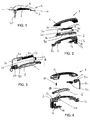
Figure 1 is a perspective side view of a handle lever according to one embodiment of the invention, -
Figure 2 is an exploded perspective side view of the handle lever offigure 1 , -
Figure 3 is an exploded perspective side view of the mobile trigger part offigure 2 , -
Figure 4 is an exploded perspective side view of the handle lever of another embodiment. - On all figures, the same references relate to the same elements.
- As shown on the
figure 2 , thehandle lever 1 of the present invention comprises: - a
lever body 3, - a
handle lever cover 5 intended be received on thelever body 3,
and - a
mobile trigger part 7, intended to cooperate with a latch mechanism (not shown) to actuate the handle (not shown) and which is able to be mobile in rotation between a resting position wherein the saidmobile trigger part 7 does not activate the said latch mechanism and an activating position wherein saidmobile trigger part 7 activates the said latch mechanism enabling the opening of the vehicle panel. - According to the invention, the
trigger part 7 comprises an inner volume 8 designed for receiving at least one electrical element. - One or several
electrical element 9 are then received inside the trigger part housing. - Such configuration enables to save space and therefore keep a slim and compact design of the handle comprising
such handle lever 1. - The said
electrical element 9 works efficiency since the motion of thetrigger part 7 does not interfere with the working of eachelectrical element 9 since the said triggerpart 7 forms a protective shell around the said at least oneelectrical element 9. - The
lever 1 and then the handle comprising such lever are efficient, reliable and easy to manufacture. The at least oneelectrical element 9 is placed in the inner volume 8 of thetrigger part 7 and then the trigger part is mounted in thelever body 3. The saidlever body 3 is then covered by thelever cover 5. - According to a variant, the
lever body 3 and thelever cover 5 may be made into one piece configured for receiving thetrigger part 7 and enabling the motion of the latter through the said one piece. - The assembly comprising the
lever body 3, thelever cover 5 and thetrigger part 7 is mounted on the vehicle panel and maybe on a specific bracket. - The vehicle panel may be for example a door, specifically a side door.
- The
lever body 3 may be of different material, for example plastics. In such case, thelever body 3 may be made by molding injection. - If the handle is configured for having both the
trigger part 7 and the handle lever mobile in rotation, the saidlever body 3 may have anend 12 capable of cooperating with an hinge of the support (not shown).Theother end 1" may be configured for receiving the body of a lock (not shown) capable of receiving the key of the user. - At this
end 13, thelever body 3 may comprise means for cooperating with an opening latch mechanism, which is represented as a main lever 14 infigure 2 . The said opening latch mechanism is able to activate a Bowden cable for activating a latch (not shown). More specifically, the said main lever 14 is associated withelastic means 15 enabling to go back to the resting position after being in the activating position. In the illustrated embodiment, the elastic means 15 are torsion spring. - The said
main lever 15 is also connected to aBowden arm 16 linked to the Bowden cable. - The
lever cover 5 may be made of any material suitable for resisting to atmospheric condition and also compatible with aesthetic aspects. The saidlever cover 5 is typically hollow for receiving thelever body 3 and thetrigger part 7. - As mentioned above, the
lever cover 5 and thelever body 3 may be made into one unique piece, for example in plastic. If thelever body 3 and thelever cover 5 are two distinct elements, these two elements may be fixed by fixing means, such as screws, clips, glue or any combination of them. - The
trigger part 7 comprises an inner volume 8 for receiving one or severalelectrical elements 9. - Advantageously, the inner volume 8 may be divided into several recesses for receiving each one or several
electrical elements 9. Each recess may be formed by a wall sensibly transversal relative to the main axis of thetrigger part 7. - In the embodiment illustrated on all figures, the handle lever has an elongated shape, such as the
lever body 3,lever cover 5 and thetrigger part 7, along a main axis 10. - Therefore, it is possible to separate at least two
electrical elements 9 in several inner volumes 8 which improves the protection of suchelectrical elements 9 and also facilitates the assembly of thehandle lever 1 of the invention. - The
mobile trigger part 7 and at least oneelectrical element 9 may be sealed together, for example with resins, in order to reach important waterproof quality. The presence of a plurality of recesses inside thetrigger part 7 facilitates the sealing step. - According to one aspect of the invention, one
electrical element 9 may be an electrical detector intended to detect the presence of at least a part of the body of an use. As an example, a hand may be cited. - The said electrical detector may be an antenna, a capacitive sensor, a Hall effect sensor or a relay reed.
- As shown in
figures 2 to 4 , the antenna 9a used may be associated with a connector 9b and linked together by one or several wires 9c. - The
trigger part 7 may have at least one opening for enabling elements, such as wire or cable, to go through the saidtrigger part 7. - One
electrical element 9 may be a micro-switch intended to operate an element, such as door latch. - The
handle lever 1 of the invention may thus receive several detectors wherein each has a specific function. There is thus no need to create space in thelever body 3 for receiving these detectors. Therefore, it is possible to save a lot of space and reaching high compactness. - According to an embodiment, the
trigger part 7 may receive one or more inertial mass 30 (seefigures 2 and 3 ). The presence of one or moreelectrical elements 9 tends to increase the mass of the trigger part. Therefore, in case of a crash event of the automotive vehicle, it may be required to add an inertial mass for preventing the opening of the panel by the unwilling activation of the latch mechanism. The inertial mass may be formed by one or severalelectrical elements 9, such as the electrical detector and/or the microswitch (seefigure 4 ). In this perspective suchelectrical element 9 may be made heavier by antenna ferrite, encapsulating resin, electronic components, printed circuit board. - The inertial mass may be a supplementary mass made in zamak®, steel or plastic material (see
figures 2 and 3 ). It is also possible to use heavier electrical element and also a supplementary inertial mass. - As shown in
figures 2 and 3 , the saidsupplementary mass 30 may be placed in arecess 80 distinct from the one of theelectrical elements 9. If several inertial masses are used, the said masses may be placed in one or in several recesses. - The
handle lever 1 of the present invention may comprise further fixing means (not shown) for maintaining the at least oneelectrical elements 9 inside the mobile trigger part. For example, such fixing means may be screws, clips, glue or any combination of them. - The
handle lever 1 of the present invention may also comprise locking means for preventing the activation of the latch mechanism when themobile trigger part 7 is in the resting position. For example, such locking means may be one orseveral pin 40 around which thetrigger part 7 is mobile in rotation. The saidpin 40 may be blocked inside the lever body. - The
mobile trigger part 7 may also be associated with elastic means 50 enabling the saidmobile trigger part 7 to come back to the resting position after having passing through the activating position. The said elastic means may be one or several compression spring. - The present invention also comprise a vehicle panel handle comprising an opening latch mechanism (not shown) configured to allow opening of the panel when actuated and a vehicle panel handle
lever 1 according to the invention and configured to actuate the opening mechanism when set in motion. The handle may also comprise a bracket on which is mounted the vehicle panel handle lever.
Claims (14)
- Vehicle panel handle lever (1) comprising :- a lever body (3),- a handle lever cover (5) intended to be received on the lever body (3),- a mobile trigger part (7), intended to cooperate with a latch mechanism to actuate the handle and which is able to be mobile in rotation between a resting position wherein the said mobile trigger part (7) does not activate the said latch mechanism and an activating position wherein said mobile trigger part (7) activates the said latch mechanism enabling the opening of the vehicle panel,
wherein the trigger part (7) comprises an inner volume (8) designed for receiving at least one electrical element (9). - Lever (1) according to any claims 1, wherein the inner volume (8) is divided into several recesses for receiving each one or several electrical elements (9).
- Lever (1) according to claim 1 or 2, wherein one electrical element is an electrical detector intended to detect the presence of at least a part of the body of an user.
- Lever (1) according to the previous claim, wherein the electrical detector is selected in the list consisting of an antenna (9a), a capacitive sensor, a Hall effect sensor and a relay reed.
- Lever (1) according to claim 1, wherein one electrical element is a microswitch intended to operate an element.
- Lever (1) according to any one of the preceding claims wherein the trigger part (7) receives one or more inertial mass (30).
- Lever (1) according to the preceding claim wherein the inertial mass (30) is made in zamak®, steel or plastic material.
- Lever (1) according to any one of the claims 3 or 4 or 5 and claim 6 or 7 wherein the inertial mass (30) is formed by the electrical element (9), such as the electrical detector or the microswitch.
- Lever (1) according to any one of preceding claims, wherein it comprises further fixing means for maintaining the at least one electrical element (9) inside the mobile trigger part (7).
- Lever (1) according to any one of the preceding claims wherein it comprises locking means (40) for preventing the activation of the latch mechanism when the mobile part lever (7) is in rest position.
- Lever (1) according to any one of the preceding claims wherein the mobile trigger part (7) is associated with elastic means (50) enabling the said mobile trigger part (7) to come back to the resting position after having passing through the activating position.
- Lever (1) according to any one of the preceding claims wherein the mobile trigger part (7) and at least one electrical element (9) is sealed together with resins.
- Vehicle panel handle for opening a panel of an automotive vehicle comprising :- an opening latch mechanism configured to allow opening of the panel when actuated,- a vehicle panel handle lever (1) according to any one of the preceding claims and configured to actuate the opening mechanism when set in motion.
- Vehicle panel handle according to the previous claim wherein it comprises a bracket on which is mounted the vehicle panel handle lever (1).
Priority Applications (11)
| Application Number | Priority Date | Filing Date | Title |
|---|---|---|---|
| EP12425149.7A EP2712986B1 (en) | 2012-09-07 | 2012-09-07 | Vehicle panel handle lever |
| EP20153645.5A EP3667001B1 (en) | 2012-09-07 | 2012-09-07 | Vehicle panel handle lever |
| MX2015003004A MX2015003004A (en) | 2012-09-07 | 2013-09-06 | Vehicle panel handle lever. |
| PCT/EP2013/068425 WO2014037478A1 (en) | 2012-09-07 | 2013-09-06 | Vehicle panel handle lever |
| KR1020157005875A KR20150052070A (en) | 2012-09-07 | 2013-09-06 | Vehicle panel handle lever |
| BR112015004612-6A BR112015004612B1 (en) | 2012-09-07 | 2013-09-06 | VEHICLE PANEL HANDLE LEVER AND VEHICLE PANEL HANDLE TO OPEN AN AUTOMOTIVE VEHICLE PANEL |
| RU2015112612A RU2673326C2 (en) | 2012-09-07 | 2013-09-06 | Vehicle panel handle lever |
| US14/425,920 US10982469B2 (en) | 2012-09-07 | 2013-09-06 | Vehicle panel handle lever |
| CN201380046794.9A CN104769200B (en) | 2012-09-07 | 2013-09-06 | Vehicle panel handlebar |
| JP2015530404A JP6317350B2 (en) | 2012-09-07 | 2013-09-06 | Handle lever for vehicle panel handle |
| IN1563DEN2015 IN2015DN01563A (en) | 2012-09-07 | 2013-09-06 |
Applications Claiming Priority (1)
| Application Number | Priority Date | Filing Date | Title |
|---|---|---|---|
| EP12425149.7A EP2712986B1 (en) | 2012-09-07 | 2012-09-07 | Vehicle panel handle lever |
Related Child Applications (2)
| Application Number | Title | Priority Date | Filing Date |
|---|---|---|---|
| EP20153645.5A Division EP3667001B1 (en) | 2012-09-07 | 2012-09-07 | Vehicle panel handle lever |
| EP20153645.5A Division-Into EP3667001B1 (en) | 2012-09-07 | 2012-09-07 | Vehicle panel handle lever |
Publications (2)
| Publication Number | Publication Date |
|---|---|
| EP2712986A1 true EP2712986A1 (en) | 2014-04-02 |
| EP2712986B1 EP2712986B1 (en) | 2020-03-11 |
Family
ID=47080400
Family Applications (2)
| Application Number | Title | Priority Date | Filing Date |
|---|---|---|---|
| EP12425149.7A Active EP2712986B1 (en) | 2012-09-07 | 2012-09-07 | Vehicle panel handle lever |
| EP20153645.5A Active EP3667001B1 (en) | 2012-09-07 | 2012-09-07 | Vehicle panel handle lever |
Family Applications After (1)
| Application Number | Title | Priority Date | Filing Date |
|---|---|---|---|
| EP20153645.5A Active EP3667001B1 (en) | 2012-09-07 | 2012-09-07 | Vehicle panel handle lever |
Country Status (10)
| Country | Link |
|---|---|
| US (1) | US10982469B2 (en) |
| EP (2) | EP2712986B1 (en) |
| JP (1) | JP6317350B2 (en) |
| KR (1) | KR20150052070A (en) |
| CN (1) | CN104769200B (en) |
| BR (1) | BR112015004612B1 (en) |
| IN (1) | IN2015DN01563A (en) |
| MX (1) | MX2015003004A (en) |
| RU (1) | RU2673326C2 (en) |
| WO (1) | WO2014037478A1 (en) |
Cited By (1)
| Publication number | Priority date | Publication date | Assignee | Title |
|---|---|---|---|---|
| WO2020120398A1 (en) * | 2018-12-13 | 2020-06-18 | Renault S.A.S | Door handle with double opening system |
Families Citing this family (20)
| Publication number | Priority date | Publication date | Assignee | Title |
|---|---|---|---|---|
| KR101628499B1 (en) * | 2014-10-17 | 2016-06-21 | 현대자동차주식회사 | Structure for preventing door opening at side impact and method for preventing door opening at side impact |
| JP6504867B2 (en) * | 2015-03-16 | 2019-04-24 | 株式会社アルファ | Vehicle door handle device |
| EP3141680B1 (en) * | 2015-09-09 | 2018-01-31 | U-Shin Italia S.p.A. | Electronic handle for a vehicle door |
| JP6499060B2 (en) * | 2015-11-13 | 2019-04-10 | 株式会社ホンダロック | Vehicle out-handle device |
| JP6660781B2 (en) * | 2016-03-17 | 2020-03-11 | 株式会社アルファ | Vehicle steering device |
| JP1576171S (en) * | 2016-09-30 | 2017-10-30 | ||
| WO2019113056A1 (en) * | 2017-12-05 | 2019-06-13 | Adac Plastics, Inc. | Door handle assembly for a motor vehicle |
| CN108049735A (en) * | 2018-01-10 | 2018-05-18 | 宁波华德汽车零部件有限公司 | A kind of outer handle of automotive electronics formula |
| US12692734B2 (en) | 2018-04-12 | 2026-07-28 | Bauer Products, Inc. | Squeeze trigger latch |
| US11692379B2 (en) * | 2018-04-12 | 2023-07-04 | Bauer Products, Inc. | Squeeze trigger latch |
| FR3081489B1 (en) * | 2018-05-25 | 2022-09-09 | U Shin Italia Spa | OPENING HANDLE DEVICE, IN PARTICULAR FOR VEHICLES |
| DE102018117954A1 (en) * | 2018-07-25 | 2020-01-30 | Huf Hülsbeck & Fürst Gmbh & Co. Kg | Automobile handle |
| JP6916764B2 (en) * | 2018-08-10 | 2021-08-11 | 株式会社ホンダロック | Vehicle door out-handle device |
| JP7067449B2 (en) * | 2018-12-12 | 2022-05-16 | トヨタ自動車株式会社 | Vehicle door structure |
| US11306519B2 (en) | 2019-04-19 | 2022-04-19 | Inteva Products, Llc | Metal traces for hall-effect sensor activation in a vehicle latch |
| DE102019113130A1 (en) * | 2019-05-17 | 2020-11-19 | Witte Automotive Gmbh | Door handle assembly |
| DE102020121603A1 (en) * | 2019-09-05 | 2021-03-11 | Huf Hülsbeck & Fürst Gmbh & Co. Kg | Actuating device with movable switching element, vehicle and actuation method |
| CN115288535B (en) * | 2022-07-05 | 2023-09-26 | 浙江极氪智能科技有限公司 | An emergency handle structure for a car door inner guard panel and a car |
| USD1061204S1 (en) * | 2023-09-01 | 2025-02-11 | Volvo Truck Corporation | Door handle |
| US12698653B2 (en) | 2024-08-08 | 2026-08-04 | Bauer Products, Inc. | Compartment door latch |
Citations (4)
| Publication number | Priority date | Publication date | Assignee | Title |
|---|---|---|---|---|
| EP1338731A2 (en) * | 2002-02-19 | 2003-08-27 | Aisin Seiki Kabushiki Kaisha | Door handle device for vehicle and door opening and closing system for vehicle applied therewith |
| DE102006029774A1 (en) * | 2006-06-27 | 2008-01-03 | Huf Hülsbeck & Fürst Gmbh & Co. Kg | Gripping device for actuating lock for opening and/or closing of e.g. door, has electronic unit for comfortable handling of gripping device, and arranged in hollow space or U-shaped projection that is present in movable gripping unit |
| WO2011061281A2 (en) * | 2009-11-20 | 2011-05-26 | Valeo Spa | Vehicle unlocking control device provided with an outer control member having an over-molded mounting |
| WO2011077222A2 (en) * | 2009-12-21 | 2011-06-30 | Illinois Tool Works Inc. | Vehicle door safety lock handle assembly |
Family Cites Families (20)
| Publication number | Priority date | Publication date | Assignee | Title |
|---|---|---|---|---|
| AU9143698A (en) * | 1997-12-03 | 1999-06-24 | Robert Bosch Gmbh | A door handle assembly |
| EP1658411B1 (en) * | 2003-08-27 | 2007-11-21 | Key Plastics LLC | Handle assembly with dual latch feature |
| JP3639292B1 (en) * | 2003-10-30 | 2005-04-20 | 株式会社アルファ | Door opener |
| JP2007510078A (en) * | 2003-11-03 | 2007-04-19 | キー プラスティクス リミテッド ライアビリティー カンパニー | External door handle with minimal surface penetration |
| US7036857B2 (en) * | 2003-12-22 | 2006-05-02 | Nissan Technical Center North America, Inc. | Vehicle inside door handle assembly |
| US7284776B2 (en) * | 2004-08-04 | 2007-10-23 | Adac Plastics, Inc. | Vehicular door handle included secondary latch |
| US7407203B2 (en) * | 2004-08-18 | 2008-08-05 | Donnelly Corporation | Vehicle door handle |
| US7527307B2 (en) * | 2005-05-13 | 2009-05-05 | Illinois Tool Works Inc. | Door handle assembly |
| DE102007011080A1 (en) * | 2007-03-07 | 2008-09-11 | Huf Hülsbeck & Fürst Gmbh & Co. Kg | External handle on doors or flaps of vehicles |
| US7866860B2 (en) * | 2008-07-22 | 2011-01-11 | Tyco Electronics Canada Ulc | Handle assembly with controlled light distribution |
| DE102009053785A1 (en) | 2009-11-19 | 2011-05-26 | BSH Bosch und Siemens Hausgeräte GmbH | A process for producing a porous pore size SiO2 xerogel by a top-down process via a precursor having organic solid skeletal supports |
| US8985645B2 (en) * | 2010-03-29 | 2015-03-24 | Janet McConnell | Systems and methods of providing foot operated latching |
| IT1400163B1 (en) * | 2010-05-19 | 2013-05-17 | Illinois Tool Works | HANDLE ASSEMBLY WITH INERTIAL SECURITY LOCKING FOR A VEHICLE DOOR |
| CN201712750U (en) * | 2010-05-20 | 2011-01-19 | 周俊龙 | Toggle Brake Locking Device |
| IT1404660B1 (en) * | 2010-06-22 | 2013-11-29 | Valeo Spa | HANDLE FOR VEHICLE DOOR INCLUDING A DECORATIVE PIECE |
| CN201771266U (en) * | 2010-08-24 | 2011-03-23 | 浙江吉利汽车研究院有限公司 | Novel automobile door handle structure for automobile |
| DE102010056436A1 (en) * | 2010-12-28 | 2012-06-28 | Magna Mirrors Holding Gmbh | Lever for an assembly for actuating a door lock |
| DE102011055289A1 (en) * | 2011-11-11 | 2013-05-16 | Huf Hülsbeck & Fürst Gmbh & Co. Kg | handle |
| ITMI20112367A1 (en) * | 2011-12-22 | 2013-06-23 | Valeo Spa | SAFETY DEVICE FOR A VEHICLE DOOR HANDLE. |
| ES2625533T3 (en) * | 2012-07-18 | 2017-07-19 | U-Shin Italia S.P.A. | Safety device for vehicle door handle |
-
2012
- 2012-09-07 EP EP12425149.7A patent/EP2712986B1/en active Active
- 2012-09-07 EP EP20153645.5A patent/EP3667001B1/en active Active
-
2013
- 2013-09-06 MX MX2015003004A patent/MX2015003004A/en unknown
- 2013-09-06 WO PCT/EP2013/068425 patent/WO2014037478A1/en not_active Ceased
- 2013-09-06 JP JP2015530404A patent/JP6317350B2/en active Active
- 2013-09-06 KR KR1020157005875A patent/KR20150052070A/en not_active Abandoned
- 2013-09-06 IN IN1563DEN2015 patent/IN2015DN01563A/en unknown
- 2013-09-06 CN CN201380046794.9A patent/CN104769200B/en active Active
- 2013-09-06 BR BR112015004612-6A patent/BR112015004612B1/en active IP Right Grant
- 2013-09-06 US US14/425,920 patent/US10982469B2/en active Active
- 2013-09-06 RU RU2015112612A patent/RU2673326C2/en not_active Application Discontinuation
Patent Citations (4)
| Publication number | Priority date | Publication date | Assignee | Title |
|---|---|---|---|---|
| EP1338731A2 (en) * | 2002-02-19 | 2003-08-27 | Aisin Seiki Kabushiki Kaisha | Door handle device for vehicle and door opening and closing system for vehicle applied therewith |
| DE102006029774A1 (en) * | 2006-06-27 | 2008-01-03 | Huf Hülsbeck & Fürst Gmbh & Co. Kg | Gripping device for actuating lock for opening and/or closing of e.g. door, has electronic unit for comfortable handling of gripping device, and arranged in hollow space or U-shaped projection that is present in movable gripping unit |
| WO2011061281A2 (en) * | 2009-11-20 | 2011-05-26 | Valeo Spa | Vehicle unlocking control device provided with an outer control member having an over-molded mounting |
| WO2011077222A2 (en) * | 2009-12-21 | 2011-06-30 | Illinois Tool Works Inc. | Vehicle door safety lock handle assembly |
Cited By (2)
| Publication number | Priority date | Publication date | Assignee | Title |
|---|---|---|---|---|
| WO2020120398A1 (en) * | 2018-12-13 | 2020-06-18 | Renault S.A.S | Door handle with double opening system |
| FR3090025A1 (en) * | 2018-12-13 | 2020-06-19 | Renault S.A.S | DOOR HANDLE WITH DOUBLE OPENING SYSTEM |
Also Published As
| Publication number | Publication date |
|---|---|
| EP3667001B1 (en) | 2023-05-10 |
| CN104769200A (en) | 2015-07-08 |
| JP2015532953A (en) | 2015-11-16 |
| KR20150052070A (en) | 2015-05-13 |
| MX2015003004A (en) | 2015-06-23 |
| CN104769200B (en) | 2018-01-05 |
| US20150225987A1 (en) | 2015-08-13 |
| RU2673326C2 (en) | 2018-11-23 |
| EP3667001A1 (en) | 2020-06-17 |
| JP6317350B2 (en) | 2018-04-25 |
| WO2014037478A1 (en) | 2014-03-13 |
| RU2015112612A (en) | 2016-10-27 |
| US10982469B2 (en) | 2021-04-20 |
| EP2712986B1 (en) | 2020-03-11 |
| BR112015004612B1 (en) | 2021-03-30 |
| BR112015004612A2 (en) | 2017-07-04 |
| IN2015DN01563A (en) | 2015-07-03 |
Similar Documents
| Publication | Publication Date | Title |
|---|---|---|
| EP2712986B1 (en) | Vehicle panel handle lever | |
| JP7419624B2 (en) | Handle device for vehicle door panel | |
| JP5480112B2 (en) | ANTENNA UNIT AND DOOR HANDLE DEVICE HAVING THE SAME | |
| US7210715B2 (en) | Door handle device | |
| JP5932708B2 (en) | Outdoor handle device for vehicle door | |
| KR101774540B1 (en) | Door handle assembly | |
| JP4052277B2 (en) | Vehicle door handle device | |
| JP5330629B2 (en) | Vehicle opening spring security system with switch without mechanical actuation | |
| CN105683464B (en) | Portable mobile wireless key | |
| US20030122556A1 (en) | Vehicle door handle system | |
| US10253530B2 (en) | Vehicle unlocking control device provided with an outer control member having an over-molded mounting | |
| CN102074399B (en) | Mobile device | |
| CN102597400B (en) | Handle device | |
| US20170346173A1 (en) | Door handle and antenna unit | |
| JP3696866B2 (en) | Door opener | |
| JP4211471B2 (en) | Waterproof switch structure | |
| JP4084640B2 (en) | Outdoor handle device for vehicle door | |
| US20210079696A1 (en) | Motor vehicle door handle arrangment with an operating module | |
| JP6438243B2 (en) | Vehicle door handle | |
| JP6099426B2 (en) | Door handle device | |
| JP3897728B2 (en) | Vehicle door handle device | |
| JP5379639B2 (en) | Door handle device | |
| US20210156174A1 (en) | Motor vehicle door handle arrangment with an emergency actuating lever | |
| JP2008240492A (en) | Vehicular out handle device |
Legal Events
| Date | Code | Title | Description |
|---|---|---|---|
| PUAI | Public reference made under article 153(3) epc to a published international application that has entered the european phase |
Free format text: ORIGINAL CODE: 0009012 |
|
| AK | Designated contracting states |
Kind code of ref document: A1 Designated state(s): AL AT BE BG CH CY CZ DE DK EE ES FI FR GB GR HR HU IE IS IT LI LT LU LV MC MK MT NL NO PL PT RO RS SE SI SK SM TR |
|
| AX | Request for extension of the european patent |
Extension state: BA ME |
|
| RAP1 | Party data changed (applicant data changed or rights of an application transferred) |
Owner name: U-SHIN ITALIA S.P.A. |
|
| 17P | Request for examination filed |
Effective date: 20141002 |
|
| RBV | Designated contracting states (corrected) |
Designated state(s): AL AT BE BG CH CY CZ DE DK EE ES FI FR GB GR HR HU IE IS IT LI LT LU LV MC MK MT NL NO PL PT RO RS SE SI SK SM TR |
|
| STAA | Information on the status of an ep patent application or granted ep patent |
Free format text: STATUS: EXAMINATION IS IN PROGRESS |
|
| 17Q | First examination report despatched |
Effective date: 20180322 |
|
| GRAP | Despatch of communication of intention to grant a patent |
Free format text: ORIGINAL CODE: EPIDOSNIGR1 |
|
| STAA | Information on the status of an ep patent application or granted ep patent |
Free format text: STATUS: GRANT OF PATENT IS INTENDED |
|
| INTG | Intention to grant announced |
Effective date: 20191111 |
|
| INTG | Intention to grant announced |
Effective date: 20191112 |
|
| GRAS | Grant fee paid |
Free format text: ORIGINAL CODE: EPIDOSNIGR3 |
|
| GRAA | (expected) grant |
Free format text: ORIGINAL CODE: 0009210 |
|
| STAA | Information on the status of an ep patent application or granted ep patent |
Free format text: STATUS: THE PATENT HAS BEEN GRANTED |
|
| AK | Designated contracting states |
Kind code of ref document: B1 Designated state(s): AL AT BE BG CH CY CZ DE DK EE ES FI FR GB GR HR HU IE IS IT LI LT LU LV MC MK MT NL NO PL PT RO RS SE SI SK SM TR |
|
| REG | Reference to a national code |
Ref country code: GB Ref legal event code: FG4D |
|
| REG | Reference to a national code |
Ref country code: CH Ref legal event code: EP |
|
| REG | Reference to a national code |
Ref country code: AT Ref legal event code: REF Ref document number: 1243323 Country of ref document: AT Kind code of ref document: T Effective date: 20200315 |
|
| REG | Reference to a national code |
Ref country code: IE Ref legal event code: FG4D |
|
| REG | Reference to a national code |
Ref country code: DE Ref legal event code: R096 Ref document number: 602012068370 Country of ref document: DE |
|
| PG25 | Lapsed in a contracting state [announced via postgrant information from national office to epo] |
Ref country code: NO Free format text: LAPSE BECAUSE OF FAILURE TO SUBMIT A TRANSLATION OF THE DESCRIPTION OR TO PAY THE FEE WITHIN THE PRESCRIBED TIME-LIMIT Effective date: 20200611 Ref country code: RS Free format text: LAPSE BECAUSE OF FAILURE TO SUBMIT A TRANSLATION OF THE DESCRIPTION OR TO PAY THE FEE WITHIN THE PRESCRIBED TIME-LIMIT Effective date: 20200311 Ref country code: FI Free format text: LAPSE BECAUSE OF FAILURE TO SUBMIT A TRANSLATION OF THE DESCRIPTION OR TO PAY THE FEE WITHIN THE PRESCRIBED TIME-LIMIT Effective date: 20200311 |
|
| REG | Reference to a national code |
Ref country code: NL Ref legal event code: MP Effective date: 20200311 |
|
| PG25 | Lapsed in a contracting state [announced via postgrant information from national office to epo] |
Ref country code: BG Free format text: LAPSE BECAUSE OF FAILURE TO SUBMIT A TRANSLATION OF THE DESCRIPTION OR TO PAY THE FEE WITHIN THE PRESCRIBED TIME-LIMIT Effective date: 20200611 Ref country code: GR Free format text: LAPSE BECAUSE OF FAILURE TO SUBMIT A TRANSLATION OF THE DESCRIPTION OR TO PAY THE FEE WITHIN THE PRESCRIBED TIME-LIMIT Effective date: 20200612 Ref country code: HR Free format text: LAPSE BECAUSE OF FAILURE TO SUBMIT A TRANSLATION OF THE DESCRIPTION OR TO PAY THE FEE WITHIN THE PRESCRIBED TIME-LIMIT Effective date: 20200311 Ref country code: LV Free format text: LAPSE BECAUSE OF FAILURE TO SUBMIT A TRANSLATION OF THE DESCRIPTION OR TO PAY THE FEE WITHIN THE PRESCRIBED TIME-LIMIT Effective date: 20200311 Ref country code: SE Free format text: LAPSE BECAUSE OF FAILURE TO SUBMIT A TRANSLATION OF THE DESCRIPTION OR TO PAY THE FEE WITHIN THE PRESCRIBED TIME-LIMIT Effective date: 20200311 |
|
| REG | Reference to a national code |
Ref country code: LT Ref legal event code: MG4D |
|
| PG25 | Lapsed in a contracting state [announced via postgrant information from national office to epo] |
Ref country code: NL Free format text: LAPSE BECAUSE OF FAILURE TO SUBMIT A TRANSLATION OF THE DESCRIPTION OR TO PAY THE FEE WITHIN THE PRESCRIBED TIME-LIMIT Effective date: 20200311 |
|
| PG25 | Lapsed in a contracting state [announced via postgrant information from national office to epo] |
Ref country code: LT Free format text: LAPSE BECAUSE OF FAILURE TO SUBMIT A TRANSLATION OF THE DESCRIPTION OR TO PAY THE FEE WITHIN THE PRESCRIBED TIME-LIMIT Effective date: 20200311 Ref country code: CZ Free format text: LAPSE BECAUSE OF FAILURE TO SUBMIT A TRANSLATION OF THE DESCRIPTION OR TO PAY THE FEE WITHIN THE PRESCRIBED TIME-LIMIT Effective date: 20200311 Ref country code: SK Free format text: LAPSE BECAUSE OF FAILURE TO SUBMIT A TRANSLATION OF THE DESCRIPTION OR TO PAY THE FEE WITHIN THE PRESCRIBED TIME-LIMIT Effective date: 20200311 Ref country code: RO Free format text: LAPSE BECAUSE OF FAILURE TO SUBMIT A TRANSLATION OF THE DESCRIPTION OR TO PAY THE FEE WITHIN THE PRESCRIBED TIME-LIMIT Effective date: 20200311 Ref country code: IS Free format text: LAPSE BECAUSE OF FAILURE TO SUBMIT A TRANSLATION OF THE DESCRIPTION OR TO PAY THE FEE WITHIN THE PRESCRIBED TIME-LIMIT Effective date: 20200711 Ref country code: SM Free format text: LAPSE BECAUSE OF FAILURE TO SUBMIT A TRANSLATION OF THE DESCRIPTION OR TO PAY THE FEE WITHIN THE PRESCRIBED TIME-LIMIT Effective date: 20200311 Ref country code: PT Free format text: LAPSE BECAUSE OF FAILURE TO SUBMIT A TRANSLATION OF THE DESCRIPTION OR TO PAY THE FEE WITHIN THE PRESCRIBED TIME-LIMIT Effective date: 20200805 Ref country code: EE Free format text: LAPSE BECAUSE OF FAILURE TO SUBMIT A TRANSLATION OF THE DESCRIPTION OR TO PAY THE FEE WITHIN THE PRESCRIBED TIME-LIMIT Effective date: 20200311 |
|
| REG | Reference to a national code |
Ref country code: AT Ref legal event code: MK05 Ref document number: 1243323 Country of ref document: AT Kind code of ref document: T Effective date: 20200311 |
|
| REG | Reference to a national code |
Ref country code: DE Ref legal event code: R097 Ref document number: 602012068370 Country of ref document: DE |
|
| PLBE | No opposition filed within time limit |
Free format text: ORIGINAL CODE: 0009261 |
|
| STAA | Information on the status of an ep patent application or granted ep patent |
Free format text: STATUS: NO OPPOSITION FILED WITHIN TIME LIMIT |
|
| PG25 | Lapsed in a contracting state [announced via postgrant information from national office to epo] |
Ref country code: ES Free format text: LAPSE BECAUSE OF FAILURE TO SUBMIT A TRANSLATION OF THE DESCRIPTION OR TO PAY THE FEE WITHIN THE PRESCRIBED TIME-LIMIT Effective date: 20200311 Ref country code: AT Free format text: LAPSE BECAUSE OF FAILURE TO SUBMIT A TRANSLATION OF THE DESCRIPTION OR TO PAY THE FEE WITHIN THE PRESCRIBED TIME-LIMIT Effective date: 20200311 Ref country code: DK Free format text: LAPSE BECAUSE OF FAILURE TO SUBMIT A TRANSLATION OF THE DESCRIPTION OR TO PAY THE FEE WITHIN THE PRESCRIBED TIME-LIMIT Effective date: 20200311 |
|
| 26N | No opposition filed |
Effective date: 20201214 |
|
| PG25 | Lapsed in a contracting state [announced via postgrant information from national office to epo] |
Ref country code: SI Free format text: LAPSE BECAUSE OF FAILURE TO SUBMIT A TRANSLATION OF THE DESCRIPTION OR TO PAY THE FEE WITHIN THE PRESCRIBED TIME-LIMIT Effective date: 20200311 Ref country code: PL Free format text: LAPSE BECAUSE OF FAILURE TO SUBMIT A TRANSLATION OF THE DESCRIPTION OR TO PAY THE FEE WITHIN THE PRESCRIBED TIME-LIMIT Effective date: 20200311 |
|
| PG25 | Lapsed in a contracting state [announced via postgrant information from national office to epo] |
Ref country code: MC Free format text: LAPSE BECAUSE OF FAILURE TO SUBMIT A TRANSLATION OF THE DESCRIPTION OR TO PAY THE FEE WITHIN THE PRESCRIBED TIME-LIMIT Effective date: 20200311 |
|
| REG | Reference to a national code |
Ref country code: CH Ref legal event code: PL |
|
| REG | Reference to a national code |
Ref country code: BE Ref legal event code: MM Effective date: 20200930 |
|
| PG25 | Lapsed in a contracting state [announced via postgrant information from national office to epo] |
Ref country code: LU Free format text: LAPSE BECAUSE OF NON-PAYMENT OF DUE FEES Effective date: 20200907 |
|
| PG25 | Lapsed in a contracting state [announced via postgrant information from national office to epo] |
Ref country code: BE Free format text: LAPSE BECAUSE OF NON-PAYMENT OF DUE FEES Effective date: 20200930 Ref country code: CH Free format text: LAPSE BECAUSE OF NON-PAYMENT OF DUE FEES Effective date: 20200930 Ref country code: IE Free format text: LAPSE BECAUSE OF NON-PAYMENT OF DUE FEES Effective date: 20200907 Ref country code: LI Free format text: LAPSE BECAUSE OF NON-PAYMENT OF DUE FEES Effective date: 20200930 |
|
| PG25 | Lapsed in a contracting state [announced via postgrant information from national office to epo] |
Ref country code: TR Free format text: LAPSE BECAUSE OF FAILURE TO SUBMIT A TRANSLATION OF THE DESCRIPTION OR TO PAY THE FEE WITHIN THE PRESCRIBED TIME-LIMIT Effective date: 20200311 Ref country code: MT Free format text: LAPSE BECAUSE OF FAILURE TO SUBMIT A TRANSLATION OF THE DESCRIPTION OR TO PAY THE FEE WITHIN THE PRESCRIBED TIME-LIMIT Effective date: 20200311 Ref country code: CY Free format text: LAPSE BECAUSE OF FAILURE TO SUBMIT A TRANSLATION OF THE DESCRIPTION OR TO PAY THE FEE WITHIN THE PRESCRIBED TIME-LIMIT Effective date: 20200311 |
|
| PG25 | Lapsed in a contracting state [announced via postgrant information from national office to epo] |
Ref country code: MK Free format text: LAPSE BECAUSE OF FAILURE TO SUBMIT A TRANSLATION OF THE DESCRIPTION OR TO PAY THE FEE WITHIN THE PRESCRIBED TIME-LIMIT Effective date: 20200311 Ref country code: AL Free format text: LAPSE BECAUSE OF FAILURE TO SUBMIT A TRANSLATION OF THE DESCRIPTION OR TO PAY THE FEE WITHIN THE PRESCRIBED TIME-LIMIT Effective date: 20200311 |
|
| PGFP | Annual fee paid to national office [announced via postgrant information from national office to epo] |
Ref country code: DE Payment date: 20250916 Year of fee payment: 14 |
|
| PGFP | Annual fee paid to national office [announced via postgrant information from national office to epo] |
Ref country code: IT Payment date: 20250909 Year of fee payment: 14 |
|
| PGFP | Annual fee paid to national office [announced via postgrant information from national office to epo] |
Ref country code: GB Payment date: 20250919 Year of fee payment: 14 |
|
| PGFP | Annual fee paid to national office [announced via postgrant information from national office to epo] |
Ref country code: FR Payment date: 20250929 Year of fee payment: 14 |