EP2712838A1 - Telescopic boom - Google Patents
Telescopic boom Download PDFInfo
- Publication number
- EP2712838A1 EP2712838A1 EP13186212.0A EP13186212A EP2712838A1 EP 2712838 A1 EP2712838 A1 EP 2712838A1 EP 13186212 A EP13186212 A EP 13186212A EP 2712838 A1 EP2712838 A1 EP 2712838A1
- Authority
- EP
- European Patent Office
- Prior art keywords
- telescopic boom
- frame
- boom
- protrusion
- protrusion portions
- Prior art date
- Legal status (The legal status is an assumption and is not a legal conclusion. Google has not performed a legal analysis and makes no representation as to the accuracy of the status listed.)
- Granted
Links
Images




Classifications
-
- B—PERFORMING OPERATIONS; TRANSPORTING
- B66—HOISTING; LIFTING; HAULING
- B66C—CRANES; LOAD-ENGAGING ELEMENTS OR DEVICES FOR CRANES, CAPSTANS, WINCHES, OR TACKLES
- B66C23/00—Cranes comprising essentially a beam, boom, or triangular structure acting as a cantilever and mounted for translatory of swinging movements in vertical or horizontal planes or a combination of such movements, e.g. jib-cranes, derricks, tower cranes
- B66C23/62—Constructional features or details
- B66C23/64—Jibs
- B66C23/70—Jibs constructed of sections adapted to be assembled to form jibs or various lengths
- B66C23/701—Jibs constructed of sections adapted to be assembled to form jibs or various lengths telescopic
Definitions
- the present invention relates to a boom used in an industrial machine or the like, or more specifically to a structure of a telescopic boom provided to, for example, a mobile crane or the like.
- a telescopic boom assembly including telescopic booms each having a closed section formed by a first frame whose section is substantially U-shaped and a second frame (see Japanese Patent Application Publication No. 2006-21877 ).
- a telescopic boom of this type has a first frame 1 whose section is substantially U-shaped and a second frame 2 attached on top of the first frame 1, and forms a closed section with the first frame 1 and the second frame 2.
- a small compartment portion 3 is formed at a center portion of the first frame 1, the small compartment portion 3 having an arc section and protruding downward.
- Small compartment portions 4 and 5 are formed on both sides of the small compartment portion 3, respectively, at positions away from the small compartment portion 3 each by a predetermined distance, the small compartment portions 4 and 5 each having an arc section and protruding outward.
- the small compartment portions 3 to 5 have the same radius.
- Improvement in the buckling strength of the first frame 1 of the telescopic boom is aimed with these three small compartment portions 3 to 5.
- the above-described telescopic boom aims to improve the buckling strength of the first frame 1 with the three small compartment portions 3 to 5, it is difficult to achieve further improvement in the buckling strength with the structure having the three small compartment portions 3 to 5.
- the present invention has an objective of providing a telescopic boom having high buckling strength.
- a telescopic boom includes: a first frame having a curved portion whose section is substantially U-shaped; and a second frame connected to the first frame so that a closed section is formed.
- a U-shaped curved portion of the first frame includes a plurality of protrusion portions formed at intervals in a circumferential direction of the telescopic boom, each protrusion portion extending in a longitudinal direction of the telescopic boom, and each of the plurality of protrusion portions is formed such that the protrusion portion has an arc-shaped section and protrudes to an outside of the first frame.
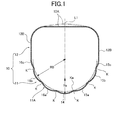
- FIG. 1 shows a section of a telescopic boom 10 of a telescopic boom assembly (not shown) of a mobile crane according to a first embodiment of the present invention.
- This telescopic boom 10 has a long first frame 11 having a section of a substantially U-shaped cup and a long second frame 12 having a cup-shaped section and being attached to an upper portion of the first frame 11.
- the telescopic boom 10 is formed by joining the first frame 11 and the second frame 12 by, for example, welding them together so that the first frame 11 and the second frame 12 form a closed section.
- the first frame 11 has a curved portion 11A formed into a U-shape, and the radius of curvature of the curved portion 11A is set to R0 (see FIG. 1 ).
- a plurality of protrusion portions 14 are formed in the curved portion 11A. These protrusion portions are provided at intervals in a circumferential direction of the telescopic boom 10 and each extend in a longitudinal direction of the telescopic boom 10. Each of the plurality of protrusion portions has an arc section and protrudes to the outside of the first frame 11.
- the radius of curvature of each protrusion portion 14 is set to Rs, and the radius of curvature R0 is set to be larger than the radius of curvature Rs so that a relational expression Rs ⁇ R0 holds true.
- one protrusion portion 14 is formed at the center portion of the curved portion 11A, and protrusion portions 15a to 15c and protrusion portions 16a to 16c are continuously formed on both sides of the protrusion portion 14 located at the center portion, respectively.
- the radius of curvature of each of the protrusion portions 15a to 15c and 16a to 16c is set equal to the radius of curvature Rs of the protrusion portion 14.
- the protrusion portions 14, 15a to 15c, and 16a to 16c are formed constantly from a lower end to an upper end of the first frame 11 of the telescopic boom 10, or in other words, as they are farther away from the peak (lower end) of the curved portion 11A, as shown in FIG. 1A , so that the amount (height) of each protrusion portion may be constant in the longitudinal direction of the telescopic boom 10 (a direction orthogonal to the paper plane in FIG. 1 ).
- a joint or node is formed at a border between the protrusion portion 14 and the protrusion portion 15a, and this joint is, for example, a recess portion K recessed when seen from the outside of the telescopic boom 10.
- This recess portion K is formed along the longitudinal direction, as shown in FIG. 1A .
- this recess portion K is configured to form a ridge portion Ka protruding to the inside of the telescopic boom 10 and extending along the longitudinal direction of the telescopic boom 10.
- the recess portion K has an R-shaped section in the embodiment shown, but may have a V-shaped section instead. Every border between adjacent ones of the protrusion portions 15a to 15c, 14, and 16a to 16c has the recess portion K similarly.
- the second frame 12 has a flat upper wall portion 12A and side wall portions 12B, 12B formed continuously on respective sides of the upper wall portion 12A.
- the upper portion of each of the side wall portions 12B, 12B is formed into an R-shape.
- the shape of the first frame 11 and the second frame 12 is symmetrical with respect to a center line L1 of the telescopic boom 10 shown in FIG. 1 .
- the plurality of protrusion portions 14, 15a to 15c, and 16a to 16c are continuously formed at the curved portion 11A of the first frame 11, and the joint (recess portion K), i.e., the ridge portion Ka is formed between every adjacent ones of the protrusion portions 14, 15a to 15c, and 16a to 16c.
- the joint (recess portion K), i.e., the ridge portion Ka is formed between every adjacent ones of the protrusion portions 14, 15a to 15c, and 16a to 16c.
- the telescopic boom 10 having the above-described configuration allows enhancement in the buckling strength more than the conventional telescopic boom does.
- FIG. 3 is a sectional view of a telescopic boom 110 of a second embodiment.
- the telescopic boom 110 has a first frame 111 having a substantially U-shaped section and a second frame 12 attached to an upper portion of the first frame 111.
- the first frame 111 has a curved portion 111A formed into a curved shape, and the radius of curvature of the curved portion 111A is set to R1.
- An arc-shaped protrusion portion 114 is formed at a center portion of the curved portion 111A, the protrusion portion 114 protruding outward (downward in FIG. 3 ).
- the radius of curvature of the protrusion portion 114 is set to Ra so that Ra ⁇ R1 may hold true.
- protrusion portions 115b, 115c and protrusion portions 116b, 116c are formed continuously on both sides of the protrusion portion 114, respectively.
- the radius of curvature of each of the protrusion portions 115b, 116b is set to Rb, and that of each of the protrusion portions 115c, 116c is set to Rc.
- the radiuses of curvature Ra to Rc of the protrusion portions 114, 115b, 115c, 116b, and 116c are set such that the farther away they are from the curved portion 111A, the larger their radiuses of curvature are. In other words, Ra ⁇ Rb ⁇ Rc ⁇ R1 holds true.
- the first frame 111 has a shape symmetrical with respect to a center line L2 of the telescopic boom 110.
- the recess portion K between each adjacent ones of the protrusion portions 114, 115b, 115c, 116b, and 116c is formed along the longitudinal direction of the telescopic boom 110, similarly with the first embodiment.
- the radius of curvature Ra of the protrusion portion 114 at the center portion of the first frame 111 on which the largest compression force acts is set to be small.
- the radiuses of curvature Rb and Rc of the protrusion portions 115b, 115c, 116b, and 116c located at the sides where a smaller compression force acts are set to be large.
- the number of the protrusion portions 114, 115b, 115c, 116b, and 116c can be reduced to thereby reduce man-hours for the work of processing them.
- the upper wall portion 12A of the second frame 12 may be formed to have an arc section protruding upward, as shown with chain lines in FIG. 1 . This way, the buckling strength of the first frame 11 or 111 of the telescopic boom 10 or 110 can be increased even more.
- the protrusion portions may be provided such that the joint between one protrusion and another protrusion is located at the center portion.
- the radiuses of curvature of the protrusion portions located on both sides of the joint are set to be the same so that the first frame 111 may be symmetrical with respect to the center line L2.
- the telescopic boom 10 or 110 in the above embodiments may be applied to any telescopic boom of the telescopic boom assembly, but is designed to be applied to one required to have high strength.
- the telescopic boom 10 or 110 is preferably applied to an intermediate telescopic boom or a top telescopic boom.
- FIG. 4 shows a rough terrain crane 210, a mobile crane, which uses the telescopic boom 10 or 110 of the above embodiments.
- the rough terrain crane 210 includes: a carrier 211 which is the main body of a vehicle having a travelling function; a left-and-right pair of front outriggers 212 provided to a front side of the carrier 211; a left-and-right pair of rear outriggers 213 provided to a rear side of the carrier 211; a slewing platform 214 attached to an upper portion of the carrier 211 such that it can slew horizontally; a cabin 220 provided to the slewing platform 214; a telescopic boom assembly 216 attached to a bracket 215 fixed to the slewing platform 214; and the like.
- the telescopic boom assembly 216 is attached at its base end portion to the bracket 215 via a support shaft 217, and can be hoisted up or down about the support shaft 217.
- a hoisting cylinder 218 is interposed between the bracket 215 and the telescopic boom assembly 216, and telescopic motion of this hoisting cylinder 218 enables the telescopic boom assembly 216 to be hoisted up and down.
- the telescopic boom assembly 216 has a base boom 216A, an intermediate boom 216B, and a top boom 216C, and is configured such that the top boom 216C is nested inside the intermediate boom 216B, which is then nested inside the base boom 216A.
- the telescopic boom assembly 216 is configured to be extended and retracted by a telescopic cylinder (not shown).
- the intermediate boom 216B and the top boom 216C have the same structure as the telescopic boom 10 or the telescopic boom 110.
- the top boom 216C is provided, at its tip end portion, with a sheave (not shown) around which a wire W is hung.
- the wire W suspends a hook block 219 to which a hook 221 is attached.
- the wire W is reeled in or out by a winch (not shown).
- the protrusion portions 14, 15a to 15c, and 16a to 16c, or 114, 115b, 115c, 116b, and 116c are formed along an arc of the radius of curvature R0 or R1, and the recess portions K are in contact with the arc of the radius of curvature R0 or R1.
- the recess portions K may be away from the arc.
- the arc may be elliptical, and the protrusion portions 14, 15a to 15c, and 16a to 16c, or 114, 115b, 115c, 116b, and 116c may be formed along the ellipse.
Landscapes
- Engineering & Computer Science (AREA)
- Mechanical Engineering (AREA)
- Jib Cranes (AREA)
Description
- The present invention relates to a boom used in an industrial machine or the like, or more specifically to a structure of a telescopic boom provided to, for example, a mobile crane or the like.
- There is conventionally known a telescopic boom assembly including telescopic booms each having a closed section formed by a first frame whose section is substantially U-shaped and a second frame (see Japanese Patent Application Publication No.
2006-21877 - As shown in
FIG. 5 , a telescopic boom of this type has afirst frame 1 whose section is substantially U-shaped and asecond frame 2 attached on top of thefirst frame 1, and forms a closed section with thefirst frame 1 and thesecond frame 2. - A
small compartment portion 3 is formed at a center portion of thefirst frame 1, thesmall compartment portion 3 having an arc section and protruding downward.Small compartment portions small compartment portion 3, respectively, at positions away from thesmall compartment portion 3 each by a predetermined distance, thesmall compartment portions small compartment portions 3 to 5 have the same radius. - Improvement in the buckling strength of the
first frame 1 of the telescopic boom is aimed with these threesmall compartment portions 3 to 5. - Although the above-described telescopic boom aims to improve the buckling strength of the
first frame 1 with the threesmall compartment portions 3 to 5, it is difficult to achieve further improvement in the buckling strength with the structure having the threesmall compartment portions 3 to 5. - The present invention has an objective of providing a telescopic boom having high buckling strength.
- To achieve the above objective, a telescopic boom according to one embodiment of the present invention includes: a first frame having a curved portion whose section is substantially U-shaped; and a second frame connected to the first frame so that a closed section is formed. In the telescopic boom, a U-shaped curved portion of the first frame includes a plurality of protrusion portions formed at intervals in a circumferential direction of the telescopic boom, each protrusion portion extending in a longitudinal direction of the telescopic boom, and each of the plurality of protrusion portions is formed such that the protrusion portion has an arc-shaped section and protrudes to an outside of the first frame.
-
-
FIG. 1 is a sectional view showing the structure of a telescopic boom according to a first embodiment of the present invention. -
FIG. 1A is a perspective view showing part of the telescopic boom. -
FIG. 2 is a partially-enlarged sectional view ofFIG. 1 . -
FIG. 3 is a sectional view of a telescopic boom of a second embodiment. -
FIG. 4 is a side view of a mobile crane equipped with the telescopic boom of the present invention. -
FIG. 5 is a sectional view showing a conventional telescopic boom. - Embodiments of a telescopic boom according to the present invention are described below with reference to the drawings.
-
FIG. 1 shows a section of atelescopic boom 10 of a telescopic boom assembly (not shown) of a mobile crane according to a first embodiment of the present invention. Thistelescopic boom 10 has a longfirst frame 11 having a section of a substantially U-shaped cup and a longsecond frame 12 having a cup-shaped section and being attached to an upper portion of thefirst frame 11. Thetelescopic boom 10 is formed by joining thefirst frame 11 and thesecond frame 12 by, for example, welding them together so that thefirst frame 11 and thesecond frame 12 form a closed section. - The
first frame 11 has acurved portion 11A formed into a U-shape, and the radius of curvature of thecurved portion 11A is set to R0 (seeFIG. 1 ). - A plurality of
protrusion portions 14 are formed in thecurved portion 11A. These protrusion portions are provided at intervals in a circumferential direction of thetelescopic boom 10 and each extend in a longitudinal direction of thetelescopic boom 10. Each of the plurality of protrusion portions has an arc section and protrudes to the outside of thefirst frame 11. The radius of curvature of eachprotrusion portion 14 is set to Rs, and the radius of curvature R0 is set to be larger than the radius of curvature Rs so that a relational expression Rs < R0 holds true. - In the first embodiment, one
protrusion portion 14 is formed at the center portion of thecurved portion 11A, andprotrusion portions 15a to 15c andprotrusion portions 16a to 16c are continuously formed on both sides of theprotrusion portion 14 located at the center portion, respectively. In this embodiment, the radius of curvature of each of theprotrusion portions 15a to 15c and 16a to 16c is set equal to the radius of curvature Rs of theprotrusion portion 14. - The
protrusion portions first frame 11 of thetelescopic boom 10, or in other words, as they are farther away from the peak (lower end) of thecurved portion 11A, as shown inFIG. 1A , so that the amount (height) of each protrusion portion may be constant in the longitudinal direction of the telescopic boom 10 (a direction orthogonal to the paper plane inFIG. 1 ). - As shown in
FIG. 2 , a joint or node is formed at a border between theprotrusion portion 14 and theprotrusion portion 15a, and this joint is, for example, a recess portion K recessed when seen from the outside of thetelescopic boom 10. This recess portion K is formed along the longitudinal direction, as shown inFIG. 1A . On the other side of thetelescopic boom 10, this recess portion K is configured to form a ridge portion Ka protruding to the inside of thetelescopic boom 10 and extending along the longitudinal direction of thetelescopic boom 10. - The recess portion K has an R-shaped section in the embodiment shown, but may have a V-shaped section instead. Every border between adjacent ones of the
protrusion portions 15a to 15c, 14, and 16a to 16c has the recess portion K similarly. - The
second frame 12 has a flatupper wall portion 12A andside wall portions upper wall portion 12A. The upper portion of each of theside wall portions - The shape of the
first frame 11 and thesecond frame 12 is symmetrical with respect to a center line L1 of thetelescopic boom 10 shown inFIG. 1 . - In the
telescopic boom 10 configured as above, the plurality ofprotrusion portions curved portion 11A of thefirst frame 11, and the joint (recess portion K), i.e., the ridge portion Ka is formed between every adjacent ones of theprotrusion portions first frame 11 in the longitudinal direction thereof is increased, whereby thefirst frame 11 can be provided with sufficient buckling strength. - In other words, the
telescopic boom 10 having the above-described configuration allows enhancement in the buckling strength more than the conventional telescopic boom does. -
FIG. 3 is a sectional view of atelescopic boom 110 of a second embodiment. Thetelescopic boom 110 has afirst frame 111 having a substantially U-shaped section and asecond frame 12 attached to an upper portion of thefirst frame 111. - The
first frame 111 has acurved portion 111A formed into a curved shape, and the radius of curvature of thecurved portion 111A is set to R1. - An arc-shaped
protrusion portion 114 is formed at a center portion of thecurved portion 111A, theprotrusion portion 114 protruding outward (downward inFIG. 3 ). The radius of curvature of theprotrusion portion 114 is set to Ra so that Ra < R1 may hold true. - In addition, in the
curved portion 111A,protrusion portions protrusion portions protrusion portion 114, respectively. The radius of curvature of each of theprotrusion portions protrusion portions - The radiuses of curvature Ra to Rc of the
protrusion portions curved portion 111A, the larger their radiuses of curvature are. In other words, Ra < Rb < Rc < R1 holds true. - The
first frame 111 has a shape symmetrical with respect to a center line L2 of thetelescopic boom 110. The recess portion K between each adjacent ones of theprotrusion portions telescopic boom 110, similarly with the first embodiment. - According to the second embodiment, the radius of curvature Ra of the
protrusion portion 114 at the center portion of thefirst frame 111 on which the largest compression force acts is set to be small. Thus, an effect similar to that offered by the first embodiment can be offered. Moreover, the radiuses of curvature Rb and Rc of theprotrusion portions protrusion portions - Although being flat in both of the embodiments above, the
upper wall portion 12A of thesecond frame 12 may be formed to have an arc section protruding upward, as shown with chain lines inFIG. 1 . This way, the buckling strength of thefirst frame telescopic boom - In addition, although the peak of the
protrusion portion first frame first frame 111 may be symmetrical with respect to the center line L2. - The
telescopic boom telescopic boom -
FIG. 4 shows arough terrain crane 210, a mobile crane, which uses thetelescopic boom - The
rough terrain crane 210 includes: acarrier 211 which is the main body of a vehicle having a travelling function; a left-and-right pair offront outriggers 212 provided to a front side of thecarrier 211; a left-and-right pair ofrear outriggers 213 provided to a rear side of thecarrier 211; aslewing platform 214 attached to an upper portion of thecarrier 211 such that it can slew horizontally; acabin 220 provided to theslewing platform 214; atelescopic boom assembly 216 attached to abracket 215 fixed to theslewing platform 214; and the like. - The
telescopic boom assembly 216 is attached at its base end portion to thebracket 215 via asupport shaft 217, and can be hoisted up or down about thesupport shaft 217. Ahoisting cylinder 218 is interposed between thebracket 215 and thetelescopic boom assembly 216, and telescopic motion of thishoisting cylinder 218 enables thetelescopic boom assembly 216 to be hoisted up and down. - The
telescopic boom assembly 216 has abase boom 216A, anintermediate boom 216B, and atop boom 216C, and is configured such that thetop boom 216C is nested inside theintermediate boom 216B, which is then nested inside thebase boom 216A. Thetelescopic boom assembly 216 is configured to be extended and retracted by a telescopic cylinder (not shown). - The
intermediate boom 216B and thetop boom 216C have the same structure as thetelescopic boom 10 or thetelescopic boom 110. - The
top boom 216C is provided, at its tip end portion, with a sheave (not shown) around which a wire W is hung. The wire W suspends ahook block 219 to which ahook 221 is attached. - The wire W is reeled in or out by a winch (not shown).
- In both of the embodiments above, the
protrusion portions protrusion portions - It should be understood that the prevent invention is not limited to the embodiments described above and can be changed or modified variously by those skilled in the art without departing from the spirit of the invention according to the claims.
Claims (9)
- A telescopic boom (10) comprising:a first frame (11) having a curved portion whose section is substantially U-shaped; anda second frame (12) connected to the first frame so that a closed section is formed,whereinthe U-shaped curved portion of the first frame includes a plurality of protrusion portions (14, 15a-15c, 16a-16c) formed at intervals in a circumferential direction of the telescopic boom, each protrusion portion extending in a longitudinal direction of the telescopic boom, andeach of the plurality of protrusion portions is formed to have an arc-shaped section and to protrude to an outside of the first frame.
- The telescopic boom according to claim 1, wherein a radius of curvature of each of the protrusion portions (14, 15a-15c, 16a-16c) is set such that the farther away the protrusion portion is from a protrusion portion located closest to a center portion of the curved portion of the first frame (11), the larger the radius of curvature of the protrusion portion is.
- The telescopic boom according to claim 1, wherein one of the plurality of protrusion portions (14, 15a-15c, 16a-16c) is positioned at a center portion of the U-shaped curved portion of the first frame (11), and the other protrusion portions are symmetrically arranged on both sides of the protrusion portion positioned at the center portion.
- The telescopic boom according to claim 2, wherein one of the plurality of protrusion portions (14, 15a-15c, 16a-16c) is positioned at the center portion of the U-shaped curved portion of the first frame, and the other protrusion portions are symmetrically arranged on both sides of the protrusion portion positioned at the center portion.
- The telescopic boom according to any one of claims 1 to 4, wherein a joint (k) is formed between each adjacent ones of the plurality of protrusion portions, the joint being recessed to an inside of the first frame.
- The telescopic boom according to any one of claims 1 to 4, wherein the telescopic boom (10) is at least one of an intermediate boom (216B) and a top boom (216C) of a base boom (216A), the intermediate boom and the top boom.
- The telescopic boom according to claim 5, wherein the telescopic boom is at least one of an intermediate boom (216B) and a top boom (216C) of a base boom (216A), the intermediate boom and the top boom.
- A mobile crane comprising the telescopic boom according to claim 6.
- A mobile crane comprising the telescopic boom according to claim 7.
Applications Claiming Priority (1)
| Application Number | Priority Date | Filing Date | Title |
|---|---|---|---|
| JP2012214055A JP6080454B2 (en) | 2012-09-27 | 2012-09-27 | Telescopic boom |
Publications (2)
| Publication Number | Publication Date |
|---|---|
| EP2712838A1 true EP2712838A1 (en) | 2014-04-02 |
| EP2712838B1 EP2712838B1 (en) | 2015-04-08 |
Family
ID=49274440
Family Applications (1)
| Application Number | Title | Priority Date | Filing Date |
|---|---|---|---|
| EP20130186212 Active EP2712838B1 (en) | 2012-09-27 | 2013-09-26 | Telescopic boom |
Country Status (4)
| Country | Link |
|---|---|
| US (1) | US9718654B2 (en) |
| EP (1) | EP2712838B1 (en) |
| JP (1) | JP6080454B2 (en) |
| CN (1) | CN103693569B (en) |
Families Citing this family (3)
| Publication number | Priority date | Publication date | Assignee | Title |
|---|---|---|---|---|
| CN105332439A (en) * | 2014-08-12 | 2016-02-17 | 中岛正爱 | Combined energy dissipation bracing component |
| DE202016003525U1 (en) * | 2016-06-03 | 2016-06-23 | Liebherr-Werk Ehingen Gmbh | Telescopic profile with variable impact |
| DE102017127973A1 (en) * | 2017-11-27 | 2019-05-29 | Liebherr-Werk Ehingen Gmbh | Telescopic boom for a crane and crane with a corresponding telescopic boom |
Citations (5)
| Publication number | Priority date | Publication date | Assignee | Title |
|---|---|---|---|---|
| BE733510A (en) * | 1969-05-23 | 1969-11-03 | ||
| EP0814050A1 (en) * | 1996-06-18 | 1997-12-29 | Kidde Industries, Inc. | Telescopic jib for vehicular cranes |
| DE19711975A1 (en) * | 1997-03-12 | 1998-09-17 | Mannesmann Ag | Telescopic jib for vehicle crane |
| JP2006021877A (en) | 2004-07-08 | 2006-01-26 | Tadano Ltd | Telescopic boom |
| WO2009029967A1 (en) * | 2007-09-05 | 2009-03-12 | Palfinger Ag | Profile shape for a crane jib |
Family Cites Families (6)
| Publication number | Priority date | Publication date | Assignee | Title |
|---|---|---|---|---|
| JPS5049868U (en) * | 1973-09-07 | 1975-05-15 | ||
| JPH0275489U (en) * | 1988-11-29 | 1990-06-08 | ||
| US20030071005A1 (en) * | 2000-03-28 | 2003-04-17 | Higgins David J. | Structural boom and pendant support |
| WO2002064485A2 (en) * | 2001-02-12 | 2002-08-22 | Vm Kraner Aps | A system for handling preferably elongated objects |
| JP2005112514A (en) * | 2003-10-06 | 2005-04-28 | Tadano Ltd | Expansion boom |
| DE102006014573B3 (en) * | 2006-03-29 | 2007-07-19 | Manitowoc Crane Group France SAS, | Telescopic crane jib part, has upper and lower profile parts with segments that are bent outwardly, and end segments adjoining each other at obtuse angle, where radius of segments is less than half width of cross-section |
-
2012
- 2012-09-27 JP JP2012214055A patent/JP6080454B2/en active Active
-
2013
- 2013-09-18 CN CN201310428622.XA patent/CN103693569B/en active Active
- 2013-09-26 EP EP20130186212 patent/EP2712838B1/en active Active
- 2013-09-27 US US14/040,276 patent/US9718654B2/en active Active
Patent Citations (5)
| Publication number | Priority date | Publication date | Assignee | Title |
|---|---|---|---|---|
| BE733510A (en) * | 1969-05-23 | 1969-11-03 | ||
| EP0814050A1 (en) * | 1996-06-18 | 1997-12-29 | Kidde Industries, Inc. | Telescopic jib for vehicular cranes |
| DE19711975A1 (en) * | 1997-03-12 | 1998-09-17 | Mannesmann Ag | Telescopic jib for vehicle crane |
| JP2006021877A (en) | 2004-07-08 | 2006-01-26 | Tadano Ltd | Telescopic boom |
| WO2009029967A1 (en) * | 2007-09-05 | 2009-03-12 | Palfinger Ag | Profile shape for a crane jib |
Also Published As
| Publication number | Publication date |
|---|---|
| JP2014065599A (en) | 2014-04-17 |
| CN103693569B (en) | 2016-01-06 |
| CN103693569A (en) | 2014-04-02 |
| US20140083968A1 (en) | 2014-03-27 |
| JP6080454B2 (en) | 2017-02-15 |
| EP2712838B1 (en) | 2015-04-08 |
| US9718654B2 (en) | 2017-08-01 |
Similar Documents
| Publication | Publication Date | Title |
|---|---|---|
| EP2712838B1 (en) | Telescopic boom | |
| US10472213B2 (en) | Lattice boom | |
| US20200031632A1 (en) | Hook device and crane | |
| JP2016108118A (en) | Counterweight device and work machine | |
| EP3112310B1 (en) | Upper turning body for crane | |
| EP2078693A1 (en) | Telescopic boom | |
| JP2019031340A (en) | Assembled state confirmation device of luffing jib | |
| US9327948B2 (en) | Telescopic boom | |
| EP3363764A1 (en) | Work machine boom | |
| CN106103333A (en) | Jib system and traveling hoist for traveling hoist | |
| US10246314B2 (en) | Wire locking structure for boom extension | |
| US8678210B1 (en) | Telescoping boom assembly with base section having primary shell and secondary formed shell | |
| KR101942213B1 (en) | Mounting structure of new boom | |
| JP2017013960A (en) | Elastic member | |
| JP6286618B2 (en) | Telescopic boom mounting structure | |
| JP6778415B2 (en) | Mobile crane | |
| JP2012041135A (en) | Mobile crane and mobile compound crane | |
| JP2017081659A (en) | Boom for work machine | |
| KR20140005517U (en) | Connection jig for crane | |
| JP6757679B2 (en) | Swing frame | |
| JP2006347722A (en) | Telescopic boom of walking crane | |
| WO2017170226A1 (en) | Revolving frame, and construction machine provided with same | |
| JP2018127181A (en) | Crawler type traveling device | |
| JP2017109804A (en) | Quay crane and quay crane manufacturing method |
Legal Events
| Date | Code | Title | Description |
|---|---|---|---|
| PUAI | Public reference made under article 153(3) epc to a published international application that has entered the european phase |
Free format text: ORIGINAL CODE: 0009012 |
|
| AK | Designated contracting states |
Kind code of ref document: A1 Designated state(s): AL AT BE BG CH CY CZ DE DK EE ES FI FR GB GR HR HU IE IS IT LI LT LU LV MC MK MT NL NO PL PT RO RS SE SI SK SM TR |
|
| AX | Request for extension of the european patent |
Extension state: BA ME |
|
| 17P | Request for examination filed |
Effective date: 20140918 |
|
| RIC1 | Information provided on ipc code assigned before grant |
Ipc: B66C 23/70 20060101AFI20141002BHEP |
|
| GRAP | Despatch of communication of intention to grant a patent |
Free format text: ORIGINAL CODE: EPIDOSNIGR1 |
|
| INTG | Intention to grant announced |
Effective date: 20141107 |
|
| GRAS | Grant fee paid |
Free format text: ORIGINAL CODE: EPIDOSNIGR3 |
|
| GRAA | (expected) grant |
Free format text: ORIGINAL CODE: 0009210 |
|
| AK | Designated contracting states |
Kind code of ref document: B1 Designated state(s): AL AT BE BG CH CY CZ DE DK EE ES FI FR GB GR HR HU IE IS IT LI LT LU LV MC MK MT NL NO PL PT RO RS SE SI SK SM TR |
|
| REG | Reference to a national code |
Ref country code: GB Ref legal event code: FG4D |
|
| REG | Reference to a national code |
Ref country code: CH Ref legal event code: EP |
|
| REG | Reference to a national code |
Ref country code: IE Ref legal event code: FG4D |
|
| REG | Reference to a national code |
Ref country code: AT Ref legal event code: REF Ref document number: 720405 Country of ref document: AT Kind code of ref document: T Effective date: 20150515 |
|
| REG | Reference to a national code |
Ref country code: DE Ref legal event code: R096 Ref document number: 602013001464 Country of ref document: DE Effective date: 20150528 |
|
| REG | Reference to a national code |
Ref country code: AT Ref legal event code: MK05 Ref document number: 720405 Country of ref document: AT Kind code of ref document: T Effective date: 20150408 |
|
| REG | Reference to a national code |
Ref country code: NL Ref legal event code: VDEP Effective date: 20150408 |
|
| REG | Reference to a national code |
Ref country code: LT Ref legal event code: MG4D |
|
| PG25 | Lapsed in a contracting state [announced via postgrant information from national office to epo] |
Ref country code: NL Free format text: LAPSE BECAUSE OF FAILURE TO SUBMIT A TRANSLATION OF THE DESCRIPTION OR TO PAY THE FEE WITHIN THE PRESCRIBED TIME-LIMIT Effective date: 20150408 |
|
| PG25 | Lapsed in a contracting state [announced via postgrant information from national office to epo] |
Ref country code: NO Free format text: LAPSE BECAUSE OF FAILURE TO SUBMIT A TRANSLATION OF THE DESCRIPTION OR TO PAY THE FEE WITHIN THE PRESCRIBED TIME-LIMIT Effective date: 20150708 Ref country code: ES Free format text: LAPSE BECAUSE OF FAILURE TO SUBMIT A TRANSLATION OF THE DESCRIPTION OR TO PAY THE FEE WITHIN THE PRESCRIBED TIME-LIMIT Effective date: 20150408 Ref country code: LT Free format text: LAPSE BECAUSE OF FAILURE TO SUBMIT A TRANSLATION OF THE DESCRIPTION OR TO PAY THE FEE WITHIN THE PRESCRIBED TIME-LIMIT Effective date: 20150408 Ref country code: FI Free format text: LAPSE BECAUSE OF FAILURE TO SUBMIT A TRANSLATION OF THE DESCRIPTION OR TO PAY THE FEE WITHIN THE PRESCRIBED TIME-LIMIT Effective date: 20150408 Ref country code: PT Free format text: LAPSE BECAUSE OF FAILURE TO SUBMIT A TRANSLATION OF THE DESCRIPTION OR TO PAY THE FEE WITHIN THE PRESCRIBED TIME-LIMIT Effective date: 20150810 Ref country code: HR Free format text: LAPSE BECAUSE OF FAILURE TO SUBMIT A TRANSLATION OF THE DESCRIPTION OR TO PAY THE FEE WITHIN THE PRESCRIBED TIME-LIMIT Effective date: 20150408 |
|
| PG25 | Lapsed in a contracting state [announced via postgrant information from national office to epo] |
Ref country code: LV Free format text: LAPSE BECAUSE OF FAILURE TO SUBMIT A TRANSLATION OF THE DESCRIPTION OR TO PAY THE FEE WITHIN THE PRESCRIBED TIME-LIMIT Effective date: 20150408 Ref country code: IS Free format text: LAPSE BECAUSE OF FAILURE TO SUBMIT A TRANSLATION OF THE DESCRIPTION OR TO PAY THE FEE WITHIN THE PRESCRIBED TIME-LIMIT Effective date: 20150808 Ref country code: AT Free format text: LAPSE BECAUSE OF FAILURE TO SUBMIT A TRANSLATION OF THE DESCRIPTION OR TO PAY THE FEE WITHIN THE PRESCRIBED TIME-LIMIT Effective date: 20150408 Ref country code: GR Free format text: LAPSE BECAUSE OF FAILURE TO SUBMIT A TRANSLATION OF THE DESCRIPTION OR TO PAY THE FEE WITHIN THE PRESCRIBED TIME-LIMIT Effective date: 20150709 Ref country code: RS Free format text: LAPSE BECAUSE OF FAILURE TO SUBMIT A TRANSLATION OF THE DESCRIPTION OR TO PAY THE FEE WITHIN THE PRESCRIBED TIME-LIMIT Effective date: 20150408 |
|
| REG | Reference to a national code |
Ref country code: DE Ref legal event code: R097 Ref document number: 602013001464 Country of ref document: DE |
|
| PG25 | Lapsed in a contracting state [announced via postgrant information from national office to epo] |
Ref country code: DK Free format text: LAPSE BECAUSE OF FAILURE TO SUBMIT A TRANSLATION OF THE DESCRIPTION OR TO PAY THE FEE WITHIN THE PRESCRIBED TIME-LIMIT Effective date: 20150408 Ref country code: EE Free format text: LAPSE BECAUSE OF FAILURE TO SUBMIT A TRANSLATION OF THE DESCRIPTION OR TO PAY THE FEE WITHIN THE PRESCRIBED TIME-LIMIT Effective date: 20150408 |
|
| PLBE | No opposition filed within time limit |
Free format text: ORIGINAL CODE: 0009261 |
|
| STAA | Information on the status of an ep patent application or granted ep patent |
Free format text: STATUS: NO OPPOSITION FILED WITHIN TIME LIMIT |
|
| PG25 | Lapsed in a contracting state [announced via postgrant information from national office to epo] |
Ref country code: SK Free format text: LAPSE BECAUSE OF FAILURE TO SUBMIT A TRANSLATION OF THE DESCRIPTION OR TO PAY THE FEE WITHIN THE PRESCRIBED TIME-LIMIT Effective date: 20150408 Ref country code: PL Free format text: LAPSE BECAUSE OF FAILURE TO SUBMIT A TRANSLATION OF THE DESCRIPTION OR TO PAY THE FEE WITHIN THE PRESCRIBED TIME-LIMIT Effective date: 20150408 Ref country code: CZ Free format text: LAPSE BECAUSE OF FAILURE TO SUBMIT A TRANSLATION OF THE DESCRIPTION OR TO PAY THE FEE WITHIN THE PRESCRIBED TIME-LIMIT Effective date: 20150408 Ref country code: RO Free format text: LAPSE BECAUSE OF NON-PAYMENT OF DUE FEES Effective date: 20150408 |
|
| 26N | No opposition filed |
Effective date: 20160111 |
|
| PG25 | Lapsed in a contracting state [announced via postgrant information from national office to epo] |
Ref country code: LU Free format text: LAPSE BECAUSE OF FAILURE TO SUBMIT A TRANSLATION OF THE DESCRIPTION OR TO PAY THE FEE WITHIN THE PRESCRIBED TIME-LIMIT Effective date: 20150926 Ref country code: MC Free format text: LAPSE BECAUSE OF FAILURE TO SUBMIT A TRANSLATION OF THE DESCRIPTION OR TO PAY THE FEE WITHIN THE PRESCRIBED TIME-LIMIT Effective date: 20150408 Ref country code: IT Free format text: LAPSE BECAUSE OF FAILURE TO SUBMIT A TRANSLATION OF THE DESCRIPTION OR TO PAY THE FEE WITHIN THE PRESCRIBED TIME-LIMIT Effective date: 20150408 |
|
| PG25 | Lapsed in a contracting state [announced via postgrant information from national office to epo] |
Ref country code: SI Free format text: LAPSE BECAUSE OF FAILURE TO SUBMIT A TRANSLATION OF THE DESCRIPTION OR TO PAY THE FEE WITHIN THE PRESCRIBED TIME-LIMIT Effective date: 20150408 |
|
| REG | Reference to a national code |
Ref country code: IE Ref legal event code: MM4A |
|
| REG | Reference to a national code |
Ref country code: FR Ref legal event code: ST Effective date: 20160531 |
|
| PG25 | Lapsed in a contracting state [announced via postgrant information from national office to epo] |
Ref country code: IE Free format text: LAPSE BECAUSE OF NON-PAYMENT OF DUE FEES Effective date: 20150926 |
|
| PG25 | Lapsed in a contracting state [announced via postgrant information from national office to epo] |
Ref country code: BE Free format text: LAPSE BECAUSE OF FAILURE TO SUBMIT A TRANSLATION OF THE DESCRIPTION OR TO PAY THE FEE WITHIN THE PRESCRIBED TIME-LIMIT Effective date: 20150408 Ref country code: FR Free format text: LAPSE BECAUSE OF NON-PAYMENT OF DUE FEES Effective date: 20150930 |
|
| PG25 | Lapsed in a contracting state [announced via postgrant information from national office to epo] |
Ref country code: MT Free format text: LAPSE BECAUSE OF FAILURE TO SUBMIT A TRANSLATION OF THE DESCRIPTION OR TO PAY THE FEE WITHIN THE PRESCRIBED TIME-LIMIT Effective date: 20150408 |
|
| REG | Reference to a national code |
Ref country code: CH Ref legal event code: PL |
|
| PG25 | Lapsed in a contracting state [announced via postgrant information from national office to epo] |
Ref country code: BG Free format text: LAPSE BECAUSE OF FAILURE TO SUBMIT A TRANSLATION OF THE DESCRIPTION OR TO PAY THE FEE WITHIN THE PRESCRIBED TIME-LIMIT Effective date: 20150408 Ref country code: HU Free format text: LAPSE BECAUSE OF FAILURE TO SUBMIT A TRANSLATION OF THE DESCRIPTION OR TO PAY THE FEE WITHIN THE PRESCRIBED TIME-LIMIT; INVALID AB INITIO Effective date: 20130926 |
|
| PG25 | Lapsed in a contracting state [announced via postgrant information from national office to epo] |
Ref country code: SE Free format text: LAPSE BECAUSE OF FAILURE TO SUBMIT A TRANSLATION OF THE DESCRIPTION OR TO PAY THE FEE WITHIN THE PRESCRIBED TIME-LIMIT Effective date: 20150408 Ref country code: CY Free format text: LAPSE BECAUSE OF FAILURE TO SUBMIT A TRANSLATION OF THE DESCRIPTION OR TO PAY THE FEE WITHIN THE PRESCRIBED TIME-LIMIT Effective date: 20150408 |
|
| PG25 | Lapsed in a contracting state [announced via postgrant information from national office to epo] |
Ref country code: CH Free format text: LAPSE BECAUSE OF NON-PAYMENT OF DUE FEES Effective date: 20160930 Ref country code: LI Free format text: LAPSE BECAUSE OF NON-PAYMENT OF DUE FEES Effective date: 20160930 |
|
| GBPC | Gb: european patent ceased through non-payment of renewal fee |
Effective date: 20170926 |
|
| PG25 | Lapsed in a contracting state [announced via postgrant information from national office to epo] |
Ref country code: SM Free format text: LAPSE BECAUSE OF FAILURE TO SUBMIT A TRANSLATION OF THE DESCRIPTION OR TO PAY THE FEE WITHIN THE PRESCRIBED TIME-LIMIT Effective date: 20150408 |
|
| PG25 | Lapsed in a contracting state [announced via postgrant information from national office to epo] |
Ref country code: MK Free format text: LAPSE BECAUSE OF FAILURE TO SUBMIT A TRANSLATION OF THE DESCRIPTION OR TO PAY THE FEE WITHIN THE PRESCRIBED TIME-LIMIT Effective date: 20150408 Ref country code: TR Free format text: LAPSE BECAUSE OF FAILURE TO SUBMIT A TRANSLATION OF THE DESCRIPTION OR TO PAY THE FEE WITHIN THE PRESCRIBED TIME-LIMIT Effective date: 20150408 |
|
| PG25 | Lapsed in a contracting state [announced via postgrant information from national office to epo] |
Ref country code: GB Free format text: LAPSE BECAUSE OF NON-PAYMENT OF DUE FEES Effective date: 20170926 |
|
| PG25 | Lapsed in a contracting state [announced via postgrant information from national office to epo] |
Ref country code: AL Free format text: LAPSE BECAUSE OF FAILURE TO SUBMIT A TRANSLATION OF THE DESCRIPTION OR TO PAY THE FEE WITHIN THE PRESCRIBED TIME-LIMIT Effective date: 20150408 |
|
| PGFP | Annual fee paid to national office [announced via postgrant information from national office to epo] |
Ref country code: DE Payment date: 20250821 Year of fee payment: 13 |