EP2712811A1 - Tool For Installing Panels - Google Patents
Tool For Installing Panels Download PDFInfo
- Publication number
- EP2712811A1 EP2712811A1 EP20120186770 EP12186770A EP2712811A1 EP 2712811 A1 EP2712811 A1 EP 2712811A1 EP 20120186770 EP20120186770 EP 20120186770 EP 12186770 A EP12186770 A EP 12186770A EP 2712811 A1 EP2712811 A1 EP 2712811A1
- Authority
- EP
- European Patent Office
- Prior art keywords
- tool
- body portion
- panel
- body members
- members
- Prior art date
- Legal status (The legal status is an assumption and is not a legal conclusion. Google has not performed a legal analysis and makes no representation as to the accuracy of the status listed.)
- Withdrawn
Links
- 238000007789 sealing Methods 0.000 claims abstract description 18
- 230000002452 interceptive effect Effects 0.000 claims abstract description 4
- 238000003780 insertion Methods 0.000 claims description 5
- 230000037431 insertion Effects 0.000 claims description 5
- 230000001419 dependent effect Effects 0.000 claims description 3
- 230000003993 interaction Effects 0.000 claims description 2
- 239000011324 bead Substances 0.000 description 13
- 238000009434 installation Methods 0.000 description 5
- 238000000034 method Methods 0.000 description 5
- 230000014509 gene expression Effects 0.000 description 2
- 230000007246 mechanism Effects 0.000 description 2
- 230000008569 process Effects 0.000 description 2
- IZMVGEWQSBMVIU-UHFFFAOYSA-N 2-(2-azaniumyl-1-hydroxycyclobutyl)acetate Chemical compound NC1CCC1(O)CC(O)=O IZMVGEWQSBMVIU-UHFFFAOYSA-N 0.000 description 1
- 229910000831 Steel Inorganic materials 0.000 description 1
- 230000006978 adaptation Effects 0.000 description 1
- 239000004411 aluminium Substances 0.000 description 1
- 229910052782 aluminium Inorganic materials 0.000 description 1
- XAGFODPZIPBFFR-UHFFFAOYSA-N aluminium Chemical compound [Al] XAGFODPZIPBFFR-UHFFFAOYSA-N 0.000 description 1
- 238000010276 construction Methods 0.000 description 1
- 230000000694 effects Effects 0.000 description 1
- 229920005570 flexible polymer Polymers 0.000 description 1
- 239000000499 gel Substances 0.000 description 1
- 239000000463 material Substances 0.000 description 1
- 229910052751 metal Inorganic materials 0.000 description 1
- 239000002184 metal Substances 0.000 description 1
- 239000002861 polymer material Substances 0.000 description 1
- 229920001296 polysiloxane Polymers 0.000 description 1
- 230000000717 retained effect Effects 0.000 description 1
- 239000000565 sealant Substances 0.000 description 1
- 238000000926 separation method Methods 0.000 description 1
- 239000010959 steel Substances 0.000 description 1
Images


Classifications
-
- E—FIXED CONSTRUCTIONS
- E04—BUILDING
- E04F—FINISHING WORK ON BUILDINGS, e.g. STAIRS, FLOORS
- E04F21/00—Implements for finishing work on buildings
- E04F21/20—Implements for finishing work on buildings for laying flooring
-
- E—FIXED CONSTRUCTIONS
- E04—BUILDING
- E04F—FINISHING WORK ON BUILDINGS, e.g. STAIRS, FLOORS
- E04F21/00—Implements for finishing work on buildings
- E04F21/20—Implements for finishing work on buildings for laying flooring
- E04F21/22—Implements for finishing work on buildings for laying flooring of single elements, e.g. flooring cramps ; flexible webs
-
- B—PERFORMING OPERATIONS; TRANSPORTING
- B64—AIRCRAFT; AVIATION; COSMONAUTICS
- B64F—GROUND OR AIRCRAFT-CARRIER-DECK INSTALLATIONS SPECIALLY ADAPTED FOR USE IN CONNECTION WITH AIRCRAFT; DESIGNING, MANUFACTURING, ASSEMBLING, CLEANING, MAINTAINING OR REPAIRING AIRCRAFT, NOT OTHERWISE PROVIDED FOR; HANDLING, TRANSPORTING, TESTING OR INSPECTING AIRCRAFT COMPONENTS, NOT OTHERWISE PROVIDED FOR
- B64F5/00—Designing, manufacturing, assembling, cleaning, maintaining or repairing aircraft, not otherwise provided for; Handling, transporting, testing or inspecting aircraft components, not otherwise provided for
- B64F5/10—Manufacturing or assembling aircraft, e.g. jigs therefor
-
- Y—GENERAL TAGGING OF NEW TECHNOLOGICAL DEVELOPMENTS; GENERAL TAGGING OF CROSS-SECTIONAL TECHNOLOGIES SPANNING OVER SEVERAL SECTIONS OF THE IPC; TECHNICAL SUBJECTS COVERED BY FORMER USPC CROSS-REFERENCE ART COLLECTIONS [XRACs] AND DIGESTS
- Y10—TECHNICAL SUBJECTS COVERED BY FORMER USPC
- Y10T—TECHNICAL SUBJECTS COVERED BY FORMER US CLASSIFICATION
- Y10T29/00—Metal working
- Y10T29/49—Method of mechanical manufacture
- Y10T29/49616—Structural member making
- Y10T29/49623—Static structure, e.g., a building component
- Y10T29/49629—Panel
Definitions
- the invention relates to a tool for use in the installation of panels, especially panels having a seal or sealing bead on or around at least part of their periphery or circumference.
- the tool of the invention is particularly suitable for use in laying floor panels, e.g. during aircraft construction, and it will be convenient to now describe the invention in this exemplary context.
- the invention is not limited to this particular application, but may also be used with other types of panels, e.g. wall or ceiling panels, in other fields.
- the elongate seals or sealing beads on or around the periphery of the panels are typically of a flexible polymer material and are designed to provide a water- or air-tight seal between the panels without the application of wet sealants, like silicone gels.
- the adjacent seals or sealing beads of adjacent panels are typically intended to bear against one another in a plane of the respective panels to achieve a desired sealing effect.
- seals or sealing beads are typically biased in the radially or peripherally outward direction, they are free to assume a maximum outward extent when there is no adjacent panel currently in place. As such, the seals or sealing beads then encroach somewhat on the neighbouring space into which an adjacent panel is to be inserted, leading to difficulties inserting the next adjacent panel.
- a tool for use in the installation of panels, especially for laying of floor panels, having the features recited in claim 1.
- Preferred features of the present invention are recited in the dependent claims.
- the invention provides a tool for installing panels, and particularly for laying floor panels, the tool comprising: an elongate body portion having a projecting edge portion configured to be inserted along a side of a panel to restrain a sealing member along the side of the panel from interference with placement or laying of an adjacent panel; wherein a length of the projecting edge portion is selectively adjustable to suit a variety of panel dimensions.
- the tool of the present invention a user is thus able to retract or to restrain the sealing member provided along a side of a panel so that it does not impede or interfere with placement or installation of an adjacent panel.
- the projecting edge portion preferably presents a smooth surface to facilitate placement or insertion of the adjacent panel along that side. Further, because the projecting edge portion is selectively adjustable, the tool of the invention can be adapted for use with different sized panels.
- the length of the projecting edge portion corresponds to, or is dependent upon, a length of the elongate body portion, and said length of the elongate body portion is selectively adjustable to suit a variety of panel dimensions.
- the elongate body portion may preferably include a plurality of body members which are serially arranged along a longitudinal axis of the elongate body portion, the plurality of body members being selectively connectable or combinable with one another to provide or form the elongate body portion in different lengths. That is, one or more of the body members may be selectively removable or separable from other body members arranged in series along the axis to provide or form the body portion in said different lengths.
- Each of the plurality of body members may therefore include a respective edge member which projects therefrom, with the body members designed to be selectively connectable or combinable with one another such that the respective edge members thereof combine to form the projecting edge portion of the tool.
- the elongate body portion of the tool is provided or supported on a frame, and one or more of the plurality of body members is selectively movable on the frame to a position separate from the other body member(s) forming the elongate body portion to provide said different lengths.
- Each of the plurality of body members which is arranged in or moved to a position separate from the elongate body portion desirably remains attached to the frame.
- each of the body members may be pivotally and/or slidably movable on the frame.
- the frame may include one or more rail member, upon which the various body members are mounted for pivoting and/or sliding movement.
- each of the body members of the tool are configured for interlocking engagement with one another along the longitudinal axis of the body portion.
- each of the body members may include one or more connection elements for interaction and/or engagement with a corresponding connection element of an adjacent body member.
- the connection elements may, for example, comprise male and female elements, such as tongue-and-groove elements or pin-and-socket elements.
- the connection elements may provide an interference fit and/or interlocking engagement of adjacent body members.
- the tool may optionally include a locking device for holding the selectively connected or combined body members fixed with respect to one another.
- the locking device may, for example, comprise a releasable clamping mechanism.
- the plurality of body members may all be of substantially the same size and shape.
- the tool includes a variety of different sized or shaped body members to obtain specific different lengths of the body portion desired.
- the individual body members of the tool may therefore be coded for various possible combinations for obtaining the specific different lengths of the elongate body portion desired.
- the tool may comprise a handle for manual insertion of the projecting edge portion along a side of a panel.
- the handle may be provided on an upper part of the body portion and/or on the frame of the tool.
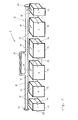
- a tool 1 for use in the installation of floor panels (not shown) is illustrated schematically and comprises an elongate body portion 2 having a projecting edge portion 3 which projects downwardly from a bottom or base part of the body portion 2.
- This projecting edge portion 3 is formed of a relatively thin, yet robust and rigid material (e.g. sheet metal, like steel or aluminium) and is configured to be inserted along a side of an installed floor panel to retract, restrain and/or retain a sealing bead (not shown) extending along that side of the floor panel from interfering with placement or installation of an adjacent floor panel.
- a rear face or surface 4 of the projecting edge portion 3 is designed to engage the elongate seal or sealing bead provided along the side of the installed floor panel while a bottom or base surface 5 of the body portion 2 seats on or against an upper surface of the installed floor panel.
- a front face or surface 6 of the elongate body portion 2 is provided substantially flat and smooth to extend continuously and uninterruptedly into the projecting edge portion 3. In this way, the front face 6 facilitates the placement or insertion of the next panel along this edge.
- the front face 6 of body portion 2 may be formed by sheet elements which project downwards from the body portion 2 to form the projecting edge portion 3, as explained further below.
- the elongate body portion 2 of the tool 1 comprises a plurality of body members 7 which are arranged in series along a longitudinal axis X of the body portion 2.
- These body members 7 have a standard or uniform cross-section in a plane perpendicular to the longitudinal axis X, but have different sizes or dimensions in the axial direction.
- the tool 1 has three different sized body members 7, which are respectively labelled A, B and C.
- These body members 7 are mounted or supported in series on a frame 8 of the tool 1, the frame 8 in this case comprising at least one rail member 9 that terminates at its opposite ends with a respective stop member 10, here in the form of a plate or disc.
- Each of the body members 7 is attached to the rail member 9 via a respective bracket 11.
- the body members 7 are movable on the frame 8 in the axial direction (e.g. via sliding movement) as well as about the axis X (e.g. rotationally or pivotally) but are nevertheless retained on the frame 8 by the stop plates 10 and the respective pivot brackets 11.
- each of the individual body members 7 has a respective edge member 12 projecting therefrom, and the plurality of body members 7 are selectively combinable such that the respective edge members 12 thereof combine to form the projecting edge portion 3 of the tool 1.
- each of the body members 7 is configured for inter-engagement with another of the plurality of body members 7 along the longitudinal axis X of the tool.
- each body member 7 in this embodiment includes at least one male and/or female connection element 13, 14 - in this case, provided in the form of a tongue element 13 and a groove element 14 for interconnection or inter-engagement with a corresponding groove or tongue element 14, 13 of an adjacent one of the body members 7.
- the tongue and groove elements 13, 14 of the respective body members 7 of the tool 1 may be configured to engage one another in a friction fit or an interference fit to provide a robust interconnection of the body members 7 such that the elongate body portion 2 remains rigidly integral in use.
- the tool 1 may further comprise a locking device 15 for holding all of the selectively connected or combined body members 7 fixed against separation from one another in the axial or longitudinal direction X.
- the locking device 15 is attached to the frame 8 and comprises a clamping mechanism with screw rods 16 that extend from the ends of the rail member 9 and act to apply a force to the body members 7 at opposite ends of the elongate body portion 2 to press the body members 7 together in the longitudinal direction X. Because a width of each edge member 12 in the axial direction corresponds to a width of the respective body member 7, a length L1 of the projecting edge portion 3 of the tool 1 along the axis X essentially corresponds to a length L2 of the elongate body portion 2 in this embodiment.
- Fig. 3 of the drawings an example of the selective adjustability of a length L1 of the projecting edge portion 3 is illustrated.
- one of the body members 7 (size C) at an end of the series of body members 7 mounted on the frame 8 is separated and spaced from the other body members 7 by sliding and pivotal movement on the rail member 9.
- the other body members 7 are interconnected with one another via the tongue-and-groove connecting elements 13, 14 and the clamping device 15 such that the elongate body portion 2 of the tool now comprises the selectively combined and interconnected series "CBAAA" of body members 7.
- CBAAA series interconnected series
- each body member which is separated from the body portion 2 of the tool 1 to reduce the length L2 thereof and thereby the length L1 of the projecting edge portion 3 may preferably be releasably held or fixed in a separated position (e.g. as shown in Fig. 3 ) so that it does not interfere with the projecting edge portion 3 of the tool during use.
- the size labels A, B, C for each of the body members 7 may be used to form codes corresponding to specific panel sizes, with the codes also telling a user of the tool 1 which body members 7 are to be combined for a particular panel size.
- these codes may include: “AA”, “BAA”, “AAA”, “BAAA”, “CBAA”, “CBAAA”, and “CBAAAC”. It will be noted that other combinations, such as “CA” and “CAAAC”, are also contemplated by the present invention, however.
- the tool 1 in the embodiment of Figs. 1 to 3 is designed for manual operation via a handle 17 attached to the frame 8.
- the user holds the tool 1 via the handle 17 and places the projecting edge portion 3 against a sealing bead (not shown) along the side of a floor panel to retract or restrain that sealing bead from interfering with placement of the next panel.
- the length L1 of the projecting edge portion 3 can be adjusted by the user to match the length of the sealing bead at the side of a variety of different panels.
- the frame 8 of the tool 1 may optionally include two or more rail members 9 that may be arranged adjacent and parallel to one another.
- the body members 7 of the tool 1 need not be connected to the same rail member 9. That is, some body members 7 may be connected to one of the rail members 9 while other body members 7 may be connected to another of the rail members 9.
- This enables greater flexibility in the combinations of the different body members 7 along the longitudinal axis X when forming the body portion 2 of the tool in different lengths L1 because, for example, centrally located body members 7 may be more easily separated or pivoted away on their respective one of the rail members 9 from the outer ones of the serially arranged body members 7.
- brackets 11 may take any of a variety of different forms, though preferably allowing both pivoting and sliding movement of the individual body members 7 on their respective rail member 9.
- the brackets 11 may include a double-ring or double-eyelet and provide more stable mounting of the body members 7 to the frame 8 for application of force to the elongate body portion 2 and projecting edge portion 3 during use of the tool 1.
- the terms “comprise”, “comprising”, “include”, “including”, “contain”, “containing”, “have”, “having”, and any variations thereof, are intended to be understood in an inclusive (i.e. non-exclusive) sense, such that the process, method, device, apparatus or system described herein is not limited to those features or parts or elements or steps recited but may include other elements, features, parts or steps not expressly listed or inherent to such process, method, article, or apparatus.
- the terms “a” and “an” used herein are intended to be understood as meaning one or more unless explicitly stated otherwise.
- the terms “first”, “second”, “third”, etc. are used merely as labels, and are not intended to impose numerical requirements on or to establish a certain ranking of importance of their objects.
Landscapes
- Engineering & Computer Science (AREA)
- Architecture (AREA)
- Manufacturing & Machinery (AREA)
- Civil Engineering (AREA)
- Structural Engineering (AREA)
- Transportation (AREA)
- Aviation & Aerospace Engineering (AREA)
- Floor Finish (AREA)
- Instrument Panels (AREA)
- Conveying And Assembling Of Building Elements In Situ (AREA)
Abstract
Description
- The invention relates to a tool for use in the installation of panels, especially panels having a seal or sealing bead on or around at least part of their periphery or circumference.
- In this regard, the tool of the invention is particularly suitable for use in laying floor panels, e.g. during aircraft construction, and it will be convenient to now describe the invention in this exemplary context. As will be appreciated by persons skilled in the art, however, the invention is not limited to this particular application, but may also be used with other types of panels, e.g. wall or ceiling panels, in other fields.
- When laying floor panels having an elongate seal or sealing bead on or around their periphery, these sealing beads can often interfere with one another when a new panel is placed or inserted adjacent an existing panel, particularly when the insertion is in the vertical direction. The elongate seals or sealing beads on or around the periphery of the panels are typically of a flexible polymer material and are designed to provide a water- or air-tight seal between the panels without the application of wet sealants, like silicone gels. To this end, the adjacent seals or sealing beads of adjacent panels are typically intended to bear against one another in a plane of the respective panels to achieve a desired sealing effect.
- Because these seals or sealing beads are typically biased in the radially or peripherally outward direction, they are free to assume a maximum outward extent when there is no adjacent panel currently in place. As such, the seals or sealing beads then encroach somewhat on the neighbouring space into which an adjacent panel is to be inserted, leading to difficulties inserting the next adjacent panel.
- It is therefore an object of the present invention to provide a new and improved tool for use in placing or laying panels, especially floor panels having a seal or sealing bead on or around at least a part of their periphery or circumference.
- In accordance with the present invention, a tool is provided for use in the installation of panels, especially for laying of floor panels, having the features recited in
claim 1. Preferred features of the present invention are recited in the dependent claims. - According to one aspect, therefore, the invention provides a tool for installing panels, and particularly for laying floor panels, the tool comprising: an elongate body portion having a projecting edge portion configured to be inserted along a side of a panel to restrain a sealing member along the side of the panel from interference with placement or laying of an adjacent panel; wherein a length of the projecting edge portion is selectively adjustable to suit a variety of panel dimensions.
- With the tool of the present invention, a user is thus able to retract or to restrain the sealing member provided along a side of a panel so that it does not impede or interfere with placement or installation of an adjacent panel. To this end, the projecting edge portion preferably presents a smooth surface to facilitate placement or insertion of the adjacent panel along that side. Further, because the projecting edge portion is selectively adjustable, the tool of the invention can be adapted for use with different sized panels.
- In a preferred embodiment, the length of the projecting edge portion corresponds to, or is dependent upon, a length of the elongate body portion, and said length of the elongate body portion is selectively adjustable to suit a variety of panel dimensions. In this regard, the elongate body portion may preferably include a plurality of body members which are serially arranged along a longitudinal axis of the elongate body portion, the plurality of body members being selectively connectable or combinable with one another to provide or form the elongate body portion in different lengths. That is, one or more of the body members may be selectively removable or separable from other body members arranged in series along the axis to provide or form the body portion in said different lengths. Each of the plurality of body members may therefore include a respective edge member which projects therefrom, with the body members designed to be selectively connectable or combinable with one another such that the respective edge members thereof combine to form the projecting edge portion of the tool.
- In a particularly preferred embodiment of the invention, the elongate body portion of the tool is provided or supported on a frame, and one or more of the plurality of body members is selectively movable on the frame to a position separate from the other body member(s) forming the elongate body portion to provide said different lengths. Each of the plurality of body members which is arranged in or moved to a position separate from the elongate body portion desirably remains attached to the frame. In this regard, each of the body members may be pivotally and/or slidably movable on the frame. For example, the frame may include one or more rail member, upon which the various body members are mounted for pivoting and/or sliding movement.
- In a particularly preferred embodiment, the body members of the tool are configured for interlocking engagement with one another along the longitudinal axis of the body portion. To this end, each of the body members may include one or more connection elements for interaction and/or engagement with a corresponding connection element of an adjacent body member. The connection elements may, for example, comprise male and female elements, such as tongue-and-groove elements or pin-and-socket elements. The connection elements may provide an interference fit and/or interlocking engagement of adjacent body members. Furthermore, the tool may optionally include a locking device for holding the selectively connected or combined body members fixed with respect to one another. The locking device may, for example, comprise a releasable clamping mechanism.
- In a preferred embodiment, the plurality of body members may all be of substantially the same size and shape. In a more preferred alternative embodiment, however, the tool includes a variety of different sized or shaped body members to obtain specific different lengths of the body portion desired. The individual body members of the tool may therefore be coded for various possible combinations for obtaining the specific different lengths of the elongate body portion desired.
- In a preferred embodiment, the tool may comprise a handle for manual insertion of the projecting edge portion along a side of a panel. The handle may be provided on an upper part of the body portion and/or on the frame of the tool.
- For a more complete understanding of the invention and the advantages thereof, exemplary embodiments of the invention are explained in more detail in the following description with reference to the accompanying drawing figures, in which like reference characters designate like parts and in which:
- Fig. 1
- is a schematic perspective view of a tool for floor panels according to an embodiment of the invention, with the body members of the tool in one particular selectively combined or interconnected state;
- Fig. 2
- is a schematic perspective view of the tool shown in
Fig. 1 , with the body members of the tool in a non-combined or loose state; and - Fig. 3
- is a schematic perspective view of the tool shown in
Fig. 1 , with the body members of the tool in an alternative selectively combined or interconnected state. - The accompanying drawings are included to provide a further understanding of the present invention and are incorporated in and constitute a part of this specification. The drawings illustrate particular embodiments of the invention and together with the description serve to explain the principles of the invention. Other embodiments of the invention and many of the attendant advantages of the invention will be readily appreciated as they become better understood with reference to the following detailed description.
- It will be appreciated that common and well understood elements that may be useful or necessary in a commercially feasible embodiment are not necessarily depicted in order to facilitate a less abstracted view of the embodiments. The elements of the drawings are not necessarily illustrated to scale relative to each other. It will further be appreciated that certain actions and/or steps in an embodiment of a method may be described or depicted in a particular order of occurrences while those skilled in the art will understand that such specificity with respect to sequence is not necessarily required. It will also be understood that the terms and expressions used in the present specification have the ordinary meaning as is accorded to such terms and expressions with respect to their corresponding respective areas of inquiry and study, except where specific meanings have otherwise been set forth herein.
- With reference to
Fig. 1 of the drawings, atool 1 according to an embodiment of the invention for use in the installation of floor panels (not shown) is illustrated schematically and comprises anelongate body portion 2 having aprojecting edge portion 3 which projects downwardly from a bottom or base part of thebody portion 2. This projectingedge portion 3 is formed of a relatively thin, yet robust and rigid material (e.g. sheet metal, like steel or aluminium) and is configured to be inserted along a side of an installed floor panel to retract, restrain and/or retain a sealing bead (not shown) extending along that side of the floor panel from interfering with placement or installation of an adjacent floor panel. In particular, a rear face or surface 4 of the projectingedge portion 3 is designed to engage the elongate seal or sealing bead provided along the side of the installed floor panel while a bottom orbase surface 5 of thebody portion 2 seats on or against an upper surface of the installed floor panel. On the other hand, a front face or surface 6 of theelongate body portion 2 is provided substantially flat and smooth to extend continuously and uninterruptedly into the projectingedge portion 3. In this way, the front face 6 facilitates the placement or insertion of the next panel along this edge. To this end, the front face 6 ofbody portion 2 may be formed by sheet elements which project downwards from thebody portion 2 to form the projectingedge portion 3, as explained further below. - With reference now also to
Fig. 2 of the drawings, it will be appreciated that theelongate body portion 2 of thetool 1 comprises a plurality ofbody members 7 which are arranged in series along a longitudinal axis X of thebody portion 2. Thesebody members 7 have a standard or uniform cross-section in a plane perpendicular to the longitudinal axis X, but have different sizes or dimensions in the axial direction. In this particular embodiment, thetool 1 has three different sizedbody members 7, which are respectively labelled A, B and C. Thesebody members 7 are mounted or supported in series on a frame 8 of thetool 1, the frame 8 in this case comprising at least one rail member 9 that terminates at its opposite ends with arespective stop member 10, here in the form of a plate or disc. Each of thebody members 7 is attached to the rail member 9 via arespective bracket 11. As a result, thebody members 7 are movable on the frame 8 in the axial direction (e.g. via sliding movement) as well as about the axis X (e.g. rotationally or pivotally) but are nevertheless retained on the frame 8 by thestop plates 10 and therespective pivot brackets 11. - As is apparent from
Figs. 1 and2 of the drawings, each of theindividual body members 7 has arespective edge member 12 projecting therefrom, and the plurality ofbody members 7 are selectively combinable such that therespective edge members 12 thereof combine to form the projectingedge portion 3 of thetool 1. In this regard, each of thebody members 7 is configured for inter-engagement with another of the plurality ofbody members 7 along the longitudinal axis X of the tool. In particular, eachbody member 7 in this embodiment includes at least one male and/orfemale connection element 13, 14 - in this case, provided in the form of atongue element 13 and agroove element 14 for interconnection or inter-engagement with a corresponding groove ortongue element body members 7. - The tongue and
groove elements respective body members 7 of thetool 1 may be configured to engage one another in a friction fit or an interference fit to provide a robust interconnection of thebody members 7 such that theelongate body portion 2 remains rigidly integral in use. To ensure that thebody members 7 of theelongate body portion 2 are not able to loosen or separate from one another in use, however, thetool 1 may further comprise alocking device 15 for holding all of the selectively connected or combinedbody members 7 fixed against separation from one another in the axial or longitudinal direction X. In this case, thelocking device 15 is attached to the frame 8 and comprises a clamping mechanism withscrew rods 16 that extend from the ends of the rail member 9 and act to apply a force to thebody members 7 at opposite ends of theelongate body portion 2 to press thebody members 7 together in the longitudinal direction X. Because a width of eachedge member 12 in the axial direction corresponds to a width of therespective body member 7, a length L1 of the projectingedge portion 3 of thetool 1 along the axis X essentially corresponds to a length L2 of theelongate body portion 2 in this embodiment. - With reference now to
Fig. 3 of the drawings, an example of the selective adjustability of a length L1 of the projectingedge portion 3 is illustrated. In this case, one of the body members 7 (size C) at an end of the series ofbody members 7 mounted on the frame 8 is separated and spaced from theother body members 7 by sliding and pivotal movement on the rail member 9. Theother body members 7 are interconnected with one another via the tongue-and-groove connecting elements clamping device 15 such that theelongate body portion 2 of the tool now comprises the selectively combined and interconnected series "CBAAA" ofbody members 7. Compared toFig. 1 , the length L1 of the projectingedge portion 3 of thetool 1 has thus been shortened to suit a different panel size or dimension with a minimum of effort. Each body member which is separated from thebody portion 2 of thetool 1 to reduce the length L2 thereof and thereby the length L1 of the projecting edge portion 3 (in this example, thebody member 7 labelled C) may preferably be releasably held or fixed in a separated position (e.g. as shown inFig. 3 ) so that it does not interfere with the projectingedge portion 3 of the tool during use. - The size labels A, B, C for each of the
body members 7 may be used to form codes corresponding to specific panel sizes, with the codes also telling a user of thetool 1 whichbody members 7 are to be combined for a particular panel size. For example, these codes may include: "AA", "BAA", "AAA", "BAAA", "CBAA", "CBAAA", and "CBAAAC". It will be noted that other combinations, such as "CA" and "CAAAC", are also contemplated by the present invention, however. - As will be understood by skilled persons, the
tool 1 in the embodiment ofFigs. 1 to 3 is designed for manual operation via ahandle 17 attached to the frame 8. In particular, the user holds thetool 1 via thehandle 17 and places the projectingedge portion 3 against a sealing bead (not shown) along the side of a floor panel to retract or restrain that sealing bead from interfering with placement of the next panel. The length L1 of the projectingedge portion 3 can be adjusted by the user to match the length of the sealing bead at the side of a variety of different panels. - Although specific embodiments of the invention have been illustrated and described herein, it will be appreciated by those of ordinary skill in the art that a variety of alternate and/or equivalent implementations exist. It should be appreciated that the exemplary embodiment or exemplary embodiments are only examples, and are not intended to limit the scope, applicability, or configuration in any way. Rather, the foregoing summary and detailed description will provide those skilled in the art with a convenient road map for implementing at least one exemplary embodiment, it being understood that various changes may be made in the function and arrangement of elements described in an exemplary embodiment without departing from the scope as set forth in the appended claims and their legal equivalents. Generally, this application is intended to cover any adaptations or variations of the specific embodiments discussed herein.
- For example, it will be appreciated that the frame 8 of the
tool 1 may optionally include two or more rail members 9 that may be arranged adjacent and parallel to one another. In this way, thebody members 7 of thetool 1 need not be connected to the same rail member 9. That is, somebody members 7 may be connected to one of the rail members 9 whileother body members 7 may be connected to another of the rail members 9. This enables greater flexibility in the combinations of thedifferent body members 7 along the longitudinal axis X when forming thebody portion 2 of the tool in different lengths L1 because, for example, centrally locatedbody members 7 may be more easily separated or pivoted away on their respective one of the rail members 9 from the outer ones of the serially arrangedbody members 7. It will also be appreciated that thebrackets 11 shown inFigs. 1 to 3 are illustrative only, such that thebrackets 11 may take any of a variety of different forms, though preferably allowing both pivoting and sliding movement of theindividual body members 7 on their respective rail member 9. In this regard, thebrackets 11 may include a double-ring or double-eyelet and provide more stable mounting of thebody members 7 to the frame 8 for application of force to theelongate body portion 2 and projectingedge portion 3 during use of thetool 1. - In this document, the terms "comprise", "comprising", "include", "including", "contain", "containing", "have", "having", and any variations thereof, are intended to be understood in an inclusive (i.e. non-exclusive) sense, such that the process, method, device, apparatus or system described herein is not limited to those features or parts or elements or steps recited but may include other elements, features, parts or steps not expressly listed or inherent to such process, method, article, or apparatus. Furthermore, the terms "a" and "an" used herein are intended to be understood as meaning one or more unless explicitly stated otherwise. Moreover, the terms "first", "second", "third", etc. are used merely as labels, and are not intended to impose numerical requirements on or to establish a certain ranking of importance of their objects.
-
- 1
- tool
- 2
- elongate body portion
- 3
- projecting edge portion
- 4
- rear face or surface of the edge portion
- 5
- bottom or base face or surface of the body portion
- 6
- front face or surface of the body and/or edge portion
- 7
- body member
- 8
- frame
- 9
- rail member
- 10
- stop member or stop plate
- 11
- bracket
- 12
- edge member
- 13
- male connection element or tongue element
- 14
- female connection element or groove element
- 15
- locking or clamping device
- 16
- screw rods
- 17
- handle
- X
- longitudinal axis
- L1
- length of the projecting edge portion
- L2
- length of the elongate body portion
Claims (14)
- A tool (1) for installing panels, especially for laying floor panels, comprising: an elongate body portion (2) having a projecting edge portion (3) configured to be inserted along a side of a panel to retain a sealing member along the side of the panel from interfering with laying of an adjacent panel;
wherein a length (L1) of the projecting edge portion (3) is selectively adjustable to suit a variety of panel dimensions. - A tool (1) according to claim 1, wherein the length (L1) of the projecting edge portion (3) corresponds to, or is dependent on, a length (L2) of the elongate body portion (2), and wherein the length (L2) of the body portion (2) is selectively adjustable to suit a variety of panel dimensions.
- A tool (1) according to claim 2, wherein the elongate body portion (2) includes a plurality of body members (7) serially arranged along a longitudinal axis (X) of the body portion (2), wherein the plurality of body members (7) are selectively combinable to form the elongate body portion (2) in different lengths.
- A tool (1) according to claim 3, wherein each of the body members (7) includes a respective edge member (12) projecting there-from, wherein the plurality of body members (7) are selectively combinable such that the respective edge members (12) thereof combine to form the projecting edge portion (3) of the tool (1).
- A tool (1) according to claim 3 or claim 4, wherein one or more of the plurality of body members (7) is/are selectively removable from the elongate body portion (2) to form said different lengths.
- A tool (1) according to any of claims 3 to 5, wherein the elongate body portion (2) is supported on a frame (8) and one or more of the plurality of body members (7) is selectively movable on the frame (8) to a position separate from the elongate body portion (2) to provide said different lengths.
- A tool (1) according to claim 6, wherein each of the plurality of body members (7) is mounted for pivoting and/or sliding movement on the frame (8).
- A tool (1) according to claim 7, wherein the frame (8) includes one or more rail member (9), on which the body members (7) are mounted for said pivoting and/or sliding movement.
- A tool (1) according to any of claims 1 to 8, wherein the body members (7) are configured for inter-engagement with one another along the longitudinal axis (X) of the body portion (3), each body member (7) including at least one connection element (13, 14) for interaction and/or engagement with a corresponding connection element (14, 13) of an adjacent body member (7).
- A tool (1) according to any of claims 1 to 9, wherein the body members (7) are coded for specific combinations for obtaining the different lengths of the elongate body portion (2) desired.
- A tool (1) according to any of claims 1 to 10, further having a locking device (15) for holding the selectively connected or combined body members (7) fixed in an axial or longitudinal direction with respect to one another.
- A tool (1) according to any of claims 1 to 11, including a handle (17) for manual insertion of the edge portion (3) along a side of a panel, wherein the handle (17) is provided on the frame (8) or an upper part of the body portion (2).
- Use of a tool (1) according to any of claims 1 to 12 for installing panels, especially for laying floor panels in an aircraft or spacecraft.
- Use of a tool (1) as claimed in claim 13, wherein each panel is placed or positioned on a supporting structure using the tool (1), and is preferably fastened to the supporting structure, for example with screws or other fasteners, after the panel is in place or in position on the supporting structure.
Priority Applications (3)
| Application Number | Priority Date | Filing Date | Title |
|---|---|---|---|
| EP20120186770 EP2712811A1 (en) | 2012-10-01 | 2012-10-01 | Tool For Installing Panels |
| US14/039,200 US20140090253A1 (en) | 2012-10-01 | 2013-09-27 | Tool for installing panels |
| CN201310460898.6A CN103711296B (en) | 2012-10-01 | 2013-10-08 | For installing the instrument of panelling |
Applications Claiming Priority (1)
| Application Number | Priority Date | Filing Date | Title |
|---|---|---|---|
| EP20120186770 EP2712811A1 (en) | 2012-10-01 | 2012-10-01 | Tool For Installing Panels |
Publications (1)
| Publication Number | Publication Date |
|---|---|
| EP2712811A1 true EP2712811A1 (en) | 2014-04-02 |
Family
ID=46970112
Family Applications (1)
| Application Number | Title | Priority Date | Filing Date |
|---|---|---|---|
| EP20120186770 Withdrawn EP2712811A1 (en) | 2012-10-01 | 2012-10-01 | Tool For Installing Panels |
Country Status (3)
| Country | Link |
|---|---|
| US (1) | US20140090253A1 (en) |
| EP (1) | EP2712811A1 (en) |
| CN (1) | CN103711296B (en) |
Families Citing this family (1)
| Publication number | Priority date | Publication date | Assignee | Title |
|---|---|---|---|---|
| CN113794173A (en) * | 2021-09-17 | 2021-12-14 | 广东电网有限责任公司广州供电局 | A kind of high-efficiency power cable protection device and installation method thereof |
Citations (5)
| Publication number | Priority date | Publication date | Assignee | Title |
|---|---|---|---|---|
| US2827086A (en) * | 1956-03-23 | 1958-03-18 | J C Minor | Implement for utilizing broken hack-saw blades |
| FR1164463A (en) * | 1957-01-15 | 1958-10-09 | Installation process for covering tiles and tools for carrying out this process | |
| DE3227356A1 (en) * | 1982-07-22 | 1984-01-26 | Denso-Chemie Wedekind Kg, 5090 Leverkusen | DEVICE FOR INSERTING A SEALING STRING OF ELASTIC MATERIAL INTO A BUILDING JOINT |
| US4586308A (en) * | 1985-06-03 | 1986-05-06 | U.S. Plywood Corporation | Wall panel |
| US20050050734A1 (en) * | 2003-09-08 | 2005-03-10 | Kesinger Donald A. | Snap knife with improved safety and usability |
Family Cites Families (8)
| Publication number | Priority date | Publication date | Assignee | Title |
|---|---|---|---|---|
| US5033178A (en) * | 1988-07-06 | 1991-07-23 | The Boeing Company | Assembly jig and method for making wing panels |
| US5134907A (en) * | 1991-08-28 | 1992-08-04 | Daniel Branson | Device for use in the installation of flooring |
| US5435610A (en) * | 1994-03-18 | 1995-07-25 | Charles Taylor | Subfloor panel driving device and method |
| US5527014A (en) * | 1994-11-10 | 1996-06-18 | Bracewell; Michael | Deck board pushing and clamping device |
| DE29507795U1 (en) * | 1995-05-11 | 1995-10-12 | Bessey & Sohn GmbH & Co, 74321 Bietigheim-Bissingen | Parquet laying aid |
| US7398628B2 (en) * | 2004-05-13 | 2008-07-15 | Van Horne Jr Jefferson | Method and apparatus for laying floors |
| EP1786994A4 (en) * | 2004-08-05 | 2011-04-27 | Paul Maxwell Travis Gaunt | Floor tool |
| US20100313714A1 (en) * | 2009-06-11 | 2010-12-16 | Smith Ronnie D | Flooring installation tool and method |
-
2012
- 2012-10-01 EP EP20120186770 patent/EP2712811A1/en not_active Withdrawn
-
2013
- 2013-09-27 US US14/039,200 patent/US20140090253A1/en not_active Abandoned
- 2013-10-08 CN CN201310460898.6A patent/CN103711296B/en not_active Expired - Fee Related
Patent Citations (5)
| Publication number | Priority date | Publication date | Assignee | Title |
|---|---|---|---|---|
| US2827086A (en) * | 1956-03-23 | 1958-03-18 | J C Minor | Implement for utilizing broken hack-saw blades |
| FR1164463A (en) * | 1957-01-15 | 1958-10-09 | Installation process for covering tiles and tools for carrying out this process | |
| DE3227356A1 (en) * | 1982-07-22 | 1984-01-26 | Denso-Chemie Wedekind Kg, 5090 Leverkusen | DEVICE FOR INSERTING A SEALING STRING OF ELASTIC MATERIAL INTO A BUILDING JOINT |
| US4586308A (en) * | 1985-06-03 | 1986-05-06 | U.S. Plywood Corporation | Wall panel |
| US20050050734A1 (en) * | 2003-09-08 | 2005-03-10 | Kesinger Donald A. | Snap knife with improved safety and usability |
Also Published As
| Publication number | Publication date |
|---|---|
| CN103711296B (en) | 2016-11-23 |
| CN103711296A (en) | 2014-04-09 |
| US20140090253A1 (en) | 2014-04-03 |
Similar Documents
| Publication | Publication Date | Title |
|---|---|---|
| DE60141015D1 (en) | FLOORING, FLOOR PLATES, METHOD FOR THE PRODUCTION THEREOF | |
| EP2708339A3 (en) | Pallet nail clinching apparatus and methods | |
| EP2075889A3 (en) | Electric installation device | |
| EP2292858A3 (en) | Fastening device for curtain wall units | |
| EP2077093A3 (en) | Surgical stapler | |
| CN103758324A (en) | Floor bottom mat for keel | |
| ITTO20090229A1 (en) | MODULAR SHEET COVER FOR BUILDING ROOFS AND FIXING BRACKET FOR THIS ROOF | |
| CN102741488A (en) | Strips with snapback hooks for vertical securing of wall panels to which they are attached | |
| EP1199188A3 (en) | Filing device. | |
| EP2980494A3 (en) | Outdoor unit for an air-conditioning apparatus | |
| US10247329B2 (en) | Cable fastener with hook structure for supporting a cable | |
| US20140090253A1 (en) | Tool for installing panels | |
| US20140123584A1 (en) | Panel mounting apparatus and related method of manufacture | |
| US9715842B2 (en) | Self tensioning mounting frame for sheet media | |
| CN207332201U (en) | Light composite stone mounting structure | |
| TR201802731T4 (en) | Rivet jointing system with rivet holder and rivet holder forming method. | |
| EP0806528A1 (en) | Fixing device for panels | |
| AU2003225607A8 (en) | System for handling folded sheet material | |
| US9692214B2 (en) | Dispenser for cable support and method | |
| CN210412903U (en) | Automatic clamping tool seat structure for gear machining | |
| JPS6033949B2 (en) | Accessible and removable support assembly for wall panels | |
| US20200102755A1 (en) | T-bar clamp for suspended ceiling grid and method of use | |
| KR101211785B1 (en) | Binder for bookbinding | |
| SE536847C2 (en) | Sign and sign suspension device | |
| GB2170748A (en) | A member for securing a partitioning panel to a frame |
Legal Events
| Date | Code | Title | Description |
|---|---|---|---|
| PUAI | Public reference made under article 153(3) epc to a published international application that has entered the european phase |
Free format text: ORIGINAL CODE: 0009012 |
|
| AK | Designated contracting states |
Kind code of ref document: A1 Designated state(s): AL AT BE BG CH CY CZ DE DK EE ES FI FR GB GR HR HU IE IS IT LI LT LU LV MC MK MT NL NO PL PT RO RS SE SI SK SM TR |
|
| AX | Request for extension of the european patent |
Extension state: BA ME |
|
| 17P | Request for examination filed |
Effective date: 20140626 |
|
| RBV | Designated contracting states (corrected) |
Designated state(s): AL AT BE BG CH CY CZ DE DK EE ES FI FR GB GR HR HU IE IS IT LI LT LU LV MC MK MT NL NO PL PT RO RS SE SI SK SM TR |
|
| 17Q | First examination report despatched |
Effective date: 20141103 |
|
| APBK | Appeal reference recorded |
Free format text: ORIGINAL CODE: EPIDOSNREFNE |
|
| APBN | Date of receipt of notice of appeal recorded |
Free format text: ORIGINAL CODE: EPIDOSNNOA2E |
|
| APBR | Date of receipt of statement of grounds of appeal recorded |
Free format text: ORIGINAL CODE: EPIDOSNNOA3E |
|
| APAF | Appeal reference modified |
Free format text: ORIGINAL CODE: EPIDOSCREFNE |
|
| APBX | Invitation to file observations in appeal sent |
Free format text: ORIGINAL CODE: EPIDOSNOBA2E |
|
| STAA | Information on the status of an ep patent application or granted ep patent |
Free format text: STATUS: EXAMINATION IS IN PROGRESS |
|
| APBT | Appeal procedure closed |
Free format text: ORIGINAL CODE: EPIDOSNNOA9E |
|
| STAA | Information on the status of an ep patent application or granted ep patent |
Free format text: STATUS: THE APPLICATION IS DEEMED TO BE WITHDRAWN |
|
| 18D | Application deemed to be withdrawn |
Effective date: 20180501 |