EP2712771A1 - Steering apparatus for motor vehicle - Google Patents
Steering apparatus for motor vehicle Download PDFInfo
- Publication number
- EP2712771A1 EP2712771A1 EP12733397.9A EP12733397A EP2712771A1 EP 2712771 A1 EP2712771 A1 EP 2712771A1 EP 12733397 A EP12733397 A EP 12733397A EP 2712771 A1 EP2712771 A1 EP 2712771A1
- Authority
- EP
- European Patent Office
- Prior art keywords
- column
- section
- plate sections
- end section
- steering
- Prior art date
- Legal status (The legal status is an assumption and is not a legal conclusion. Google has not performed a legal analysis and makes no representation as to the accuracy of the status listed.)
- Granted
Links
Images




Classifications
-
- B—PERFORMING OPERATIONS; TRANSPORTING
- B62—LAND VEHICLES FOR TRAVELLING OTHERWISE THAN ON RAILS
- B62D—MOTOR VEHICLES; TRAILERS
- B62D5/00—Power-assisted or power-driven steering
- B62D5/04—Power-assisted or power-driven steering electrical, e.g. using an electric servo-motor connected to, or forming part of, the steering gear
- B62D5/0403—Power-assisted or power-driven steering electrical, e.g. using an electric servo-motor connected to, or forming part of, the steering gear characterised by constructional features, e.g. common housing for motor and gear box
-
- B—PERFORMING OPERATIONS; TRANSPORTING
- B62—LAND VEHICLES FOR TRAVELLING OTHERWISE THAN ON RAILS
- B62D—MOTOR VEHICLES; TRAILERS
- B62D1/00—Steering controls, i.e. means for initiating a change of direction of the vehicle
- B62D1/02—Steering controls, i.e. means for initiating a change of direction of the vehicle vehicle-mounted
- B62D1/16—Steering columns
-
- B—PERFORMING OPERATIONS; TRANSPORTING
- B62—LAND VEHICLES FOR TRAVELLING OTHERWISE THAN ON RAILS
- B62D—MOTOR VEHICLES; TRAILERS
- B62D1/00—Steering controls, i.e. means for initiating a change of direction of the vehicle
- B62D1/02—Steering controls, i.e. means for initiating a change of direction of the vehicle vehicle-mounted
- B62D1/16—Steering columns
- B62D1/18—Steering columns yieldable or adjustable, e.g. tiltable
- B62D1/184—Mechanisms for locking columns at selected positions
-
- B—PERFORMING OPERATIONS; TRANSPORTING
- B62—LAND VEHICLES FOR TRAVELLING OTHERWISE THAN ON RAILS
- B62D—MOTOR VEHICLES; TRAILERS
- B62D5/00—Power-assisted or power-driven steering
- B62D5/04—Power-assisted or power-driven steering electrical, e.g. using an electric servo-motor connected to, or forming part of, the steering gear
-
- B—PERFORMING OPERATIONS; TRANSPORTING
- B62—LAND VEHICLES FOR TRAVELLING OTHERWISE THAN ON RAILS
- B62D—MOTOR VEHICLES; TRAILERS
- B62D1/00—Steering controls, i.e. means for initiating a change of direction of the vehicle
- B62D1/02—Steering controls, i.e. means for initiating a change of direction of the vehicle vehicle-mounted
- B62D1/16—Steering columns
- B62D1/18—Steering columns yieldable or adjustable, e.g. tiltable
- B62D1/187—Steering columns yieldable or adjustable, e.g. tiltable with tilt adjustment; with tilt and axial adjustment
Definitions
- the present invention relates to a steering apparatus for an automobile that is used for applying a steering angle to the steered wheels, and particularly, relates to construction of a connecting section between the front end section of the steering column and the housing of an electric power steering apparatus in a steering apparatus for an automobile provided with an electric power steering apparatus.
- a steering apparatus for an automobile is constructed, for example, so that rotation of a steering wheel 1 is transmitted to an input shaft 3 of a steering-gear unit 2, and as the input shaft 3 rotates, a pair of left and right tie rods 4 are pushed and pulled so as to apply a steering angle to the front wheels (steered wheels).
- the steering wheel 1 is supported by and fastened to the rear-end section of a steering shaft 5, and with this steering shaft 5 inserted into a cylindrical shaped steering column 6, the steering shaft 5 is supported by the steering column 6 so as to be able to rotate freely.
- the front-end section of the steering shaft 5 is connected to the rear-end section of an intermediate shaft 8 by way of a universal joint 7, and the front-end section of this intermediate shaft 8 is connected to the input shaft 3 by way of a separate universal joint 9.
- the steering apparatus for an automobile that is illustrated in the figures, together with comprising an electric power steering apparatus 10 that assists the operator steer by way of rotation of a motor, also comprises a tilt mechanism for adjusting the up-down position of the steering wheel, and a telescopic mechanism for adjusting the forward-backward position of the steering wheel 1. Therefore, the front-end section of the steering column 6 fits with and fastens to the rear-end section of a housing 11 that houses the component parts of the electric power steering apparatus 10, and this housing 11 is supported by the vehicle body 12 so as to be able to pivot around a horizontal shaft 13 that is arranged in the left-right direction.
- the steering shaft 5 comprises a combination of an inner shaft 15 and an outer shaft 16 that are capable of transmitting rotation force and are capable of relative displacement in the axial direction.
- the steering column 6 comprises a combination of an inner column 17 and an outer column 18 that are capable of relative displacement in the axial direction.
- the portion near the rear end of the outer column 18 is supported by a vehicle-side bracket 19 that is supported by the vehicle body 19 so that the fastened state to the vehicle side bracket 19 can be switched between a fastened state and unfastened state.
- a pair of holding plate sections 20 of the vehicle-side bracket 19 are arranged at a position on both sides in the left-right direction of the portion near the rear end of the outer column 18 and a column-side bracket 21 that is attached and fastened to the bottom surface of this portion near the rear end.
- Arc-shaped long holes 22 in the up-down direction that center around the horizontal shaft 13 are formed at positions in these holding plate sections 20 so as to be aligned with each other.
- long holes 23 that are long in the forward-backward direction in the axial direction of the outer column 18 are formed at positions in the side plate sections of the column-side bracket 21 so as to be aligned with each other.
- the adjustment rod 24, the adjustment nut 26 and the adjustment lever 27 form an expanding-contracting mechanism for switching between the fastened state and unfastened state between the vehicle-side bracket 19 and the steering column 6.
- the adjustment lever 27 When adjusting the up-down position and the forward-backward direction of the steering wheel 1, the adjustment lever 27 is operated, and by loosening the adjustment nut 26 the distance between the inside surfaces of the holding plate sections 20 is expanded. As a result, the friction force that acts between the holding plate sections 20 and the side plate sections of the column-side bracket 21 is sufficiently decreased, and the fastened state of the outer column 18 to the vehicle-side bracket 19 is released. In this state, when the up-down position of the steering wheel 1 is adjusted, the steering column 6 and steering wheel 1 are pivoted around the horizontal shaft 13 within a range that the adjustment rod 24 can displace inside long hole 22 in the up-down direction.
- the adjustment rod 24 can displace inside the long hole 23 in the forward-backward direction.
- the adjustment lever 27 is operated, and the adjustment nut 26 is tightened. By doing so, the friction force is sufficiently increased, and the outer column 18 is fastened to the vehicle-side bracket 19. As a result, the steering wheel 1 is held in the adjusted position.
- JP2011-46309(A ) discloses construction in which the cylindrical shaped front-end section of the steering column is pressed onto and fits around a cylindrical shaped section that is formed on the rear end section of the housing with an interference fit.
- JP2000-85596(A ) discloses a method in which the front end section of a steering column having a notched cylindrical shape fits around a cylindrical section that is formed on the rear-end section of the housing, then a fastener fits around this front end section and by elastically constricting the diameter of the front-end section with this fastener, the inner surface of the front-end section forms a strong friction fit with the outer circumferential surface of the cylindrical section.
- JP2008-87583(A ) discloses construction in which the cylindrical shaped front-end section of the steering column fits inside a circular hold that is formed on the rear-end section of the housing, and a flange section that is formed around the outer circumferential surface of the portion near the front end of the steering column is connected and fastened to the rear-end surface of the housing with a plurality of bolts.
- the assembled direction of the steering column 6 with respect to the housing 11 when assembling this connection is in the axial direction of the steering column 6.
- this portion near the rear end of the steering column 6 is inserted between the holding plate sections 20 of the vehicle-side bracket 19 from the bottom edge side of these holding plate sections 20.
- the assembly direction of the steering column 6 in the vehicle-side bracket 19 is in the radial direction of the steering column 6. In this way, in the case of the conventional construction, the assembly direction of the steering column 6 in the housing 11 and the assembly direction of the steering column 6 in the vehicle-side bracket 19 are different.
- the object of the present invention to provide construction of a steering apparatus for an automobile wherein the assembly direction of the steering column in the housing of the electric steering apparatus and the assembly direction of the steering column in the vehicle-side support bracket coincide with each other.
- the steering apparatus for an automobile of the present invention has a steering column, a housing that is supported by the vehicle body and that houses an electric power steering apparatus, a vehicle-side bracket that is supported by the vehicle body, and an expansion and contraction mechanism.
- the steering column has a front-end section that is formed in a U-shape that is open at the top and comprises a pair of left and right side plate sections that face each other and a bottom plate section that connects to the edges on the bottom ends of these side plate sections.
- the housing for an electric power steering apparatus has a connection and fastening section on the rear that is capable of being inserted inside the front-end section of the steering column through an opening in the top end of the front-end section, and when inserted inside the front-end section is capable of a non-circular fit in the front-end section.
- the vehicle-side bracket has a pair of holding plate sections that are located at positions on both the left and right sides of the middle section of the steering column, with the portion between the edges on bottom edges being open.
- the expansion and contraction mechanism comprises a rod shaped member that is inserted in the left-right direction through through holes that are formed in positions of the holding plate sections that are aligned with each other, and a pair of pressing sections that are provided on both end sections of the rod shaped member.
- the expansion and contraction mechanism is constructed such that by moving these pressing sections away from each other or close to each other in the axial direction of the rod shape member, the distance between the holding plate sections is changed, and when this space is contracted, the expansion and contraction mechanism fastens the steering column to these holding plate sections
- connection and fastening section With the connection and fastening section being fitted with a non-circular fit inside the front-end section, the connection and fastening section and the front-end section of the steering column are connected and fastened together by a bolt.
- through holes in the left-right direction are formed at positions in side plate sections of the front-end section of the steering column and in the connection and fastening section of the housing that are aligned with each other; and together with inserting a bolt through these through holes that are formed in the side plate sections and the connection and fastening section, a nut is screwed on the tip end section of the bolt.
- more than one set of the through holes is formed in the side plate sections and the connection and fastening section, and together with inserting a bolt through each of the through holes, a nut is screwed on the tip end section of the bolt.
- the present invention can be applied to a steering apparatus that comprises a tilt mechanism for making it possible to adjust the up-down position of the steering wheel that is fastened to the rear-end section of the steering shaft.
- the housing is supported by the vehicle body so as to be able to pivotally displace around a horizontal shaft that is arranged in the left-right direction.
- the through holes in the holding plate sections are long holes in the up-down direction that are arc shaped around the center of the horizontal shaft, a through hole is formed in the middle section of the steering column at a position that is aligned with the long holes in the up-down direction, and the rod member is inserted through the long holes in the up-down direction of the housing and the through hole of the steering column.
- the up-down position of the steering column can be adjusted within the range that the rod shaped member can displace in the long holes in the up-down direction.
- the present invention can be applied to construction that comprises a telescopic mechanism for making it possible to adjust the forward-backward position of the steering wheel.
- the steering column comprises a front column that is located on the front side, and a rear column that is located on the rear side and assembled so as to be able to displace relative to the front column.
- a front-end section is formed on the front column.
- a through hole is formed in the rear section of the front column at a position that is aligned with through holes in the holding plate sections.
- a long hole in the forward-backward direction that is long in the axial direction of the rear column is formed in the rear column at a position that is aligned with through holes in the holding plate sections and the through holes in the front column.
- the rod shaped member is inserted through the through holes in the holding plate sections, the through holes in the front column and the long holes in the forward-backward direction of the rear column.
- the front column is an outer column, and this entire outer column is formed in a U-shape that is open at the top with the side plate sections and the bottom plate section.
- the rear column is an inner column and is such that the front section of this inner column fits inside the rear section of the outer column.
- the expansion and contraction mechanism expands or contracts the inner dimension of the rear section of the outer column by changing the distancee between the holding plate sections, such that when the inner dimension is contracted, displacement in the axial direction of the inner column with respect to the outer column is suppressed, and when the inner dimension is expanded, displacement in the axial direction of the inner column with respect to the outer column is possible.
- through holes are formed in the left-right direction at positions in the side plate sections of the outer column and in the connection and fastening section of the housing that are aligned with each other, and together with inserting a bolt through these through holes that are formed in the side plate sections and the connection and fastening section, a nut is screwed on the tip end section of the bolt.
- the through holes that are formed in the side plate section through which the bolt is inserted, and the through holes that are formed in the rear section of the side plate sections through which the rod shaped member is inserted are respectively formed in portions near the openings on the top end of the side plate sections.
- the steering apparatus for an automobile of the present invention it is possible to make the assembly direction of the steering column in the vehicle-side bracket and the assembly direction of the steering column in the housing for the electric power steering apparatus coincide with each other. Therefore, the work for this assembly can be performed in one process, and thus it is possible to improve the ease of assembly of the steering apparatus.
- the middle section of the steering column is inserted between the pair of holding plate sections from the bottom edge side of the holding plate sections. That is, the assembly direction of the steering column in the vehicle-side bracket is in the radial direction of the steering column (direction from the bottom surface toward the top surface).
- the connection and fastening section that is provided on the rear section of the housing is inserted into the front-end section of the steering column through an opening in the top end of the front-end section. That is, the assembly direction of the steering column in the housing is also in the radial direction of the steering column (direction from the bottom surface toward the top surface).
- the steering apparatus for an automobile of this example comprises a steering column 6a, a steering shaft 5a, a housing 11a for an electric power steering apparatus 10a, a vehicle-side bracket 19a, an energy-absorbing member 28 as an attached member and an expansion and contraction mechanism 29.
- the steering column 6a comprises an outer column 18a that is front column, and an inner column 17a that is a rear column, that are combined so as to be capable of relative displacement in the axial direction.
- the outer column 18a is formed by using a press to perform punching or bending of a metal plate material such as carbon steel plate having sufficient strength and rigidity, and is formed into a U shape that is open at the top comprising a pair of left and right side plate sections 30, the inside surface of which face each other, and a bottom plate section 31 that is connected to the edges on the bottom ends of these side plate sections 30.
- both end sections in the width direction of the bottom plate section 31 are inclined at 45 degrees with respect to both the center section in the width direction of the bottom plate section and the side plate sections 30.
- the dimension in the up-down direction of the side plate sections 30 is comparatively large on the rear-end section and comparatively small on the front-end section, and in the portion between the rear-end section and the front-end section, the dimension changes so as to become smaller going toward the front-end side.
- the bending rigidity of the side plate sections 30 is maintained by forming a plurality of stiffening beads in both the rear-end section and the middle section of the side plate sections 30, and by forming flange sections by bending the top ends of the middle sections 90 degrees toward the outside in the horizontal direction. Furthermore, restraining blocks 32 are fastened to the portion near the top end of the rear-end section of the inside surfaces of the side plate sections 30 by bolts, welding or the like. The bottom surfaces of these restraining blocks 32 are also inclined 45 degrees with respect to the side plate sections 30 and the center section in the width direction of the bottom plate section 31.
- the portion that is surrounded by the inside surfaces of the side plate sections 30, the top surface of the bottom plate section 31 and the bottom surface of the restraining blocks 32 is such that the center section in the width direction is open toward the top, and forms nearly an octagonal shaped holding space.
- the inner column 17a is formed by performing desired plastic working or milling on the end section of an intermediate material that is integrally formed by extrusion or drawing of a metal material containing a light alloy such as an aluminum alloy, magnesium alloy or the like.
- the outer perimeter surface of the inner column is an octagonal shape.
- the front section of this inner column 17a fits inside the rear section of the outer column 18a such that the forward-backward position is adjustable according to displacement in the axial direction.
- the entire steering column can be formed into an arbitrary column shape, and only the front end section is formed into a U shape that is open at the top end by a pair of left and right side plate sections that face each other and a bottom plate section that connects the edges on the bottom ends of the side plate sections.
- the steering shaft 5a is such that by combining the rear section of the inner shaft 15a on the front side and the front section of the outer shaft 16 on the rear side by a spline fit, the inner shaft 15a and the outer shaft 16a are capable of transmitting rotation force, and are capable of relative displacement in the axial direction. With this construction, the entire length of the steering shaft 5a is able to expand and contract.
- the steering shaft 5a passes through the inside of the steering column 6a, and the portion near the rear end of the outer shaft 16a is supported by the rear-end section of the inner column 17a by a bearing such as a single-row deep-groove ball bearing that is capable of supporting both radial loads and thrust loads so that steering shaft 5a can rotate freely.
- a bearing such as a single-row deep-groove ball bearing that is capable of supporting both radial loads and thrust loads so that steering shaft 5a can rotate freely.
- An electric motor 14a which is an auxiliary driving source, is supported on one side of the upper portion of the housing 11a for the electric power steering apparatus 10a.
- the housing 11a houses a plurality of component parts including a reduction gear 34 for transmitting the rotation driving force of the electric motor 14a to the steering shaft 5a.
- a support tube 35 is provided in the left-right direction at the top end section at the front of the housing 11a. The housing 11a is supported by the vehicle body such that it can pivotally displace around a horizontal shaft such as a bolt that is inserted through the support tube 35.
- the steering shaft 5a to which the steering wheel is fastened to the rear-end section, and the steering column 6a that supports the steering shaft 5a are able to displace in the up-down direction. Therefore, in construction that does not comprise a tilting mechanism the housing 11a can be supported by and fastened to the vehicle body by rigid construction.
- connection and fasting section 36 is provided in the center section of the rear-end surface of the housing 11a, and protrudes toward the outer column 18a side.
- the outer perimeter surface of this connection and fastening section 36 has a rectangular shaped cross section, and together with being able to be inserted into the front-end section of the outer column 18a through an opening on the top end of the front-end section, as illustrated in FIG. 5 , when inserted inside the front-end section, makes a non-circular fit with the front-end section.
- the shape of the connection and fastening section 36 can be any arbitrary shape other than a rectangular shape as long as it can be inserted into the front-end section of the outer column 18a and can make a non-circular fit with the front-end section.
- connection and fastening section 36 is such that when inserted inside the front-end section of the outer column 18a, the surfaces on the left and right sides of the connection and fastening section 36 come in contact with the inside surfaces of the pair of side plate sections 30 of the outer column 18a, and the center section in the width direction on the bottom surface of the connection and fastening section 36 comes in contact with the center section in the width direction of the bottom plate section 31 of the outer column 18a.
- through holes 37, 38 in the left-right direction are formed in two locations in the forward-backward direction of portions near the top ends of the connection and fastening section 36 and the side plate sections 30 that are aligned with each other.
- Fastening bolts 39 are inserted through each of the through holes 37, 38 that are formed at these two locations in the forward-backward direction, and fastening nuts 40 are screwed onto the tip end sections of these fastening bolts 39 and tightened. Then, by firmly holding the connection and fastening section 36 and the side plate sections 30 by the head sections 41 on the base end sections of the fastening bolts 39 and the fastening nuts 40, the connection and fastening section 36 and front-end section of the outer column 18a are connected and fastened together. Furthermore, in this state, the front-end section of the inner shaft 15a is inserted inside the housing 11a through a center hole in the connection and fastening section 36 and connected to component parts of the electric power steering apparatus 10a that are housed inside the housing 11a.
- the vehicle-side bracket 19a comprises a top plate section 42 and a pair of holding plate sections 20a, 20b.
- the top plate section 42 and holding plate sections 20a, 20b are formed by using a press to perform punching and bending of metal plate such as steel plate having sufficient strength and rigidity, and connected and fastened together to form a single piece by welding or the like. Installation holes, through which bolts or studs are passed in order to support the top plate section 42 and fasten the top plate section 42 to the vehicle body, are formed in the top plate section 42.
- holding plate sections 20a, 20b are placed at positions on both sides in the left-right direction of the rear-end section of the outer column 18a.
- Long holes 22a, 22b that are long in the up-down direction are formed at positions in the top portions of the holding plate sections 20a, 20b that are aligned with each other.
- the long holes 22a, 22b in the up-down direction are arc shaped around the center axis of the support tube 35.
- an energy-absorbing member 28 which is a component of the inner column 17a, is attached and fastened to the top surface of the front-end section of the inner column 17a.
- This energy-absorbing member is formed by bending metal plate, such as mild steel plate that is capable of plastic deformation, into a long rectangular frame shape that is long in the forward-backward direction, and an installation plate section 43 protrudes forward from the bottom-end section of the front-end surface thereof.
- An installation member 44 such as a rivet or screw that is inserted a through hole that is formed in this installation plate section 43 attaches and fastens the energy-absorbing member 28 to the inner column 17a.
- This energy-absorbing member 28 expands due to plastic deformation that occurs during a secondary collision that accompanies a collision accident, and allows the inner column 17a to displace in the forward direction together with the steering wheel. By this means, it is possible to protect the operator by absorbing energy that is transmitted from the body of the operator to the inner column 17a by way of the steering wheel during a secondary collision.
- the expansion and contraction mechanism 29 is to expand and contract the distance between the inside surfaces of the holding plate sections 20a, 20b, and comprises an adjustment rod 24a, which is a rod shaped member, an adjustment lever 27a, and a cam device 45.
- the adjustment rod 24a is inserted in the left-right direction through the long holes 22a, 22b in the up-down direction, through holes 46 that are formed in the side plate sections 30 and restraining blocs 32 of the outer column 18a, and long hole 23a in the forward-backward direction that is long in the axial direction of the inner column 17a and formed in the inside of the energy-absorbing member that is attached to the inner column 17a.
- the adjustment rod 24a is such that a head section 25a is formed on the base end section (right end section in FIG. 4 and FIG. 7 ), and a convex section that is formed on the inside surface of this head section 25a fits inside one of the long holes 22a in the up-down direction that is formed on one holding plate section 20a of the two holding plate sections 20a, 20b (right holding plate section in FIG. 4 and FIG. 7 ) so as to be able to displace (move up or down) only along this long hole 22a in the up-down direction.
- the adjustment lever 27a is such that the base end section is supported by the tip end section (left end section of FIG. 4 and FIG.
- the long hole 23a in the forward-backward direction can also be formed in the inner column 17a itself, or can be formed in a separate member that is attached to the inner column 17a.
- the cam device 45 is provided between the inside surface on the base end section of the adjustment lever 27a and the outside surface of the other holding plate section 20b of the two holding plate sections 20a, 20b (left holding plate section in FIG. 4 and FIG. 7 ).
- the cam device 45 comprises a driving cam 49 that is supported by the inside surface of the base end section of the adjustment lever 27a and that rotates together with the adjustment lever 27a, and a driven cam 50 that fits in the other long hole 22b in the up-down direction that is formed in the other holding plate section 20b so as to be able to move only up or down.
- Cam surfaces are formed on the surfaces of the driven cam 50 and the driving cam 49 that face each other, and due to relative rotation between the driven cam 50 and driving cam 49, the dimension in the axial direction of the cam device 45 expands or contracts.
- the head section 25a and the driven cam 50 form a pair of pressing sections.
- Spacers 51a, 51b which are formed using a material such as synthetic resin that slides easily, are placed over positions in the middle section of the adjustment rod 24a that are located on the inside of the long holes 22a, 22b in the up-down direction, making it possible for the adjustment rod 24a to smoothly displace along the long holes 22a, 22b in the up-down direction.
- a cylindrical radial sliding bearing 52 that is made using a material that slides easily is located between the inner circumferential surface of the driving cam 49 and the outer circumferential surface of the adjustment rod 24a.
- the dimension in the axial direction of the cam device 45 is shortened by rotating the adjustment lever 27a in the downward direction.
- the distance between the inside surfaces of the holding plate sections 20a, 20b is expanded and the surface pressure at the area of contact between the inside surfaces of these holding plate sections 20a, 20b and the outside surfaces of the side plate sections 30 of the outer column 18a is sufficiently reduced.
- the distance between the side plate sections 30 and the restraining blocks 32 is expanded, and the surface pressure at the area of contact between the outer circumferential surface of the inner column 17 and inner circumferential surface of the outer column 18a is sufficiently reduced.
- the state of the outer column 18a and inner column 17a being fastened to the vehicle-side bracket 19a is released.
- the steering column 6a and the steering shaft 5a are pivoted around the support tube 35 within the range that the adjustment rod 24a can displace inside the long holes 22a, 22b in the up-down direction.
- construction is provided for increasing the support strength for supporting the steering wheel in the adjusted up-down position.
- the base section of a pivot arm 53 is fitted over the portion of the adjustment rod 24a near the tip end of the middle section so as to be able to pivot and displace.
- a male gear 54 is provided on the tip end section of the pivot arm 53 and a female gear 55 is provided on part of the outside surface of the holding plate section 20b, and as the pivot arm 53 pivots, the male gear 54 and female gear 55 can be placed in either the engaged state or released state.
- the adjustment lever 27a is rotated in a direction for adjusting the position of the steering wheel, the pivot arm 53 is pivoted in a direction that releases the engagement between the male gear 54 and the female gear 55.
- the adjustment rod 24a is connected with the holding plate section 20b by way of the pivot arm 53, so regardless of whether there is a large impact load during a secondary collision, the up-down position of the steering wheel does not move a large amount.
- the driven cam 50 is assembled to the base section of the pivot arm 53 so as to be able to rotate relative to the pivot arm 53 as well as to be able to displace a little in the up-down direction with respect to the pivot arm 53.
- the driven cam 50 as described above, is such that relative rotation with respect to the holding plate section 20b is prevented.
- a restoring spring 56 is provided between the driven cam 50 and the pivot arm 53 such that the driven cam 50 is supported on the pivot arm 53 so as to be able move up or down a little about a neutral position.
- the assembly direction of the steering column 6a in the vehicle-side bracket 19a coincide with the assembly direction of the steering column 6a in the housing 11a.
- the middle portion of the steering column 6a (rear-end section of the outer column 18a) is inserted between the pair of holding plate sections 20a, 20b of the vehicle-side bracket 19a from the bottom end edge side of these holding plate sections 20a, 20b. That is, the assembly direction of the steering column 6a with respect to the vehicle-side bracket 19a is in the radial direction of the steering column 6a (direction from the bottom surface toward the top surface).
- connection and fastening section 36 that is provided on the rear-end section of the housing 11a is inserted into the front-end section of the steering column 6a (front-end section of the outer column 18a) from an opening on the top end of this front-end section. That is, the assembly direction of the steering column 6a with respect to the housing 11a can also be in the radial direction of the steering column 6a (direction from the bottom surface toward the top surface).
- the housing 11a and the vehicle-side bracket 19a are set in a holding tool with the positional relationship illustrated in FIG. 6 , and in this state, the front-end section and the middle section of the steering column 6a can be assembled into the connection and fastening section 36 of the housing 11a and the pair of holding plate sections 20a, 20b of the vehicle-side bracket 19a in the radial direction of the steering column 6a from the bottom in FIG. 6 . Therefore, assembling the steering column 6a in the vehicle-side support bracket 19a and assembling the steering column 6a in the housing 11a can be performed in one process, and thus it is possible to improve the ease of assembly of the steering apparatus by that amount. The actual work is performed in the positional relationship of up-and-down is opposite from the positional relationship illustrated in FIG. 6 .
- connection and fastening section 36 inside the front-end section of the steering column 6a and the work of inserting the middle section of the steering column 6a into the portion between the holding plate sections 20a, 20b can be performed in order as described below.
- the housing 11a and the vehicle-side support bracket 19a are set in a holding tool with the positional relationship illustrated in FIG. 6 , and then only the housing 11a is pivoted and displaced around the support tube 35 toward the bottom in FIG. 6 .
- the connection and fastening section 36 is inserted inside the front-end section of the steering column 6a through opening in the top ends of the front-end section.
- the housing 11a and the steering column 6a are pivoted and displaced around the support tube 35 toward the top in FIG. 6 , and the middle section of the steering column 6a is inserted into the portion between the holding plate sections 20a, 20b.
- the phase in the rotational direction of the steering column 6a is in the proper phase, and this proper phase is maintained, so it becomes easy to perform the following insertion work.
- the two insertions described above can be performed in one process on an assembly line for the steering apparatus.
- the work of inserting the connection and fastening section 36 inside the front-end section of the steering column 6a through an opening on the top ends of the front-end section is performed in a state wherein the steering shaft 5a is not placed inside the steering column 6a, or is performed in a state wherein the front-end section of the steering shaft that has been placed inside the steering column 6a is moved sufficiently out of the way toward the rear. In this way, the front-end section of the steering shaft 5a is prevented from hindering the insertion work.
- connection and fastening section 36 and the side plate sections 30 are fastened together at the portion near an opening on the top end of the side plate sections 30 (opposite side from the bottom plate section 31) by fastening bolts 39, so the side plate sections 30 bend or bow and are firmly tightened to the connection and fastening section 36.
- the expansion and contraction mechanism 29 is also constructed so as to be inserted into through holes 46 that are formed in portions near the top end of the side plate sections 30, so in the fastened state, the side plate sections 30 bend or bow, so the tightening force by this expansion and contraction mechanism 29 is tight with respect to the steering column 6a.
- the insertion direction of the adjustment rod 24a through the through holes 46, and the insertion direction of the fastening bolts 39 through the through holes 37, 38 are in the left-right direction, and coincide with each other, so it is possible to further improve the ease of assembly of the steering apparatus.
- a combination of through holes 37, 38, fastening bolts 39 and fastening nuts 40 that is used for connecting and fastening the connection and fastening section 36 and the front-end section of the steering column 6a is provided at two locations that are separated in the forward-backward direction. Therefore, it is possible to sufficiently maintain the bending rigidity of the connecting section between the connection and fastening section 36 and the front-end section of the steering column 6a.
- the present invention is applied to construction that comprises both a tilt mechanism for making it possible to adjust the up-down position of the steering wheel, and a telescopic mechanism for making it possible to adjust the forward-backward position of the steering wheel.
- the present invention can also be applied to construction that comprises only one of these mechanisms.
Landscapes
- Engineering & Computer Science (AREA)
- Chemical & Material Sciences (AREA)
- Combustion & Propulsion (AREA)
- Transportation (AREA)
- Mechanical Engineering (AREA)
- Steering Controls (AREA)
- Power Steering Mechanism (AREA)
Abstract
Description
- The present invention relates to a steering apparatus for an automobile that is used for applying a steering angle to the steered wheels, and particularly, relates to construction of a connecting section between the front end section of the steering column and the housing of an electric power steering apparatus in a steering apparatus for an automobile provided with an electric power steering apparatus.
- As illustrated in
FIG. 8 andFIG. 9 , a steering apparatus for an automobile is constructed, for example, so that rotation of asteering wheel 1 is transmitted to aninput shaft 3 of a steering-gear unit 2, and as theinput shaft 3 rotates, a pair of left andright tie rods 4 are pushed and pulled so as to apply a steering angle to the front wheels (steered wheels). Thesteering wheel 1 is supported by and fastened to the rear-end section of asteering shaft 5, and with thissteering shaft 5 inserted into a cylindricalshaped steering column 6, thesteering shaft 5 is supported by thesteering column 6 so as to be able to rotate freely. Moreover, the front-end section of thesteering shaft 5 is connected to the rear-end section of anintermediate shaft 8 by way of a universal joint 7, and the front-end section of thisintermediate shaft 8 is connected to theinput shaft 3 by way of a separateuniversal joint 9. - The steering apparatus for an automobile that is illustrated in the figures, together with comprising an electric
power steering apparatus 10 that assists the operator steer by way of rotation of a motor, also comprises a tilt mechanism for adjusting the up-down position of the steering wheel, and a telescopic mechanism for adjusting the forward-backward position of thesteering wheel 1. Therefore, the front-end section of thesteering column 6 fits with and fastens to the rear-end section of ahousing 11 that houses the component parts of the electricpower steering apparatus 10, and thishousing 11 is supported by thevehicle body 12 so as to be able to pivot around ahorizontal shaft 13 that is arranged in the left-right direction. Thesteering shaft 5 comprises a combination of aninner shaft 15 and anouter shaft 16 that are capable of transmitting rotation force and are capable of relative displacement in the axial direction. On the other hand, thesteering column 6 comprises a combination of aninner column 17 and anouter column 18 that are capable of relative displacement in the axial direction. Furthermore, the portion near the rear end of theouter column 18 is supported by a vehicle-side bracket 19 that is supported by thevehicle body 19 so that the fastened state to thevehicle side bracket 19 can be switched between a fastened state and unfastened state. - In order to achieve this kind of support construction, a pair of
holding plate sections 20 of the vehicle-side bracket 19 are arranged at a position on both sides in the left-right direction of the portion near the rear end of theouter column 18 and a column-side bracket 21 that is attached and fastened to the bottom surface of this portion near the rear end. Arc-shapedlong holes 22 in the up-down direction that center around thehorizontal shaft 13 are formed at positions in theseholding plate sections 20 so as to be aligned with each other. Moreover,long holes 23 that are long in the forward-backward direction in the axial direction of theouter column 18 are formed at positions in the side plate sections of the column-side bracket 21 so as to be aligned with each other. Anadjustment rod 24, which is a rod shaped member, is inserted in the forward-backwardlong holes 23 and the up-downlong holes 22. Ahead section 25, which is a pressing section, is formed on the base-end section of thisadjustment rod 24. Anadjustment nut 26, which is a pressing section, is screwed onto the portion of the tip end section of thisadjustment rod 24 that protrudes from the up-down hole 22, and the base-end section of anadjustment lever 27 is connected and fastened to thisadjustment nut 26. In the construction illustrated in the figure, theadjustment rod 24, theadjustment nut 26 and the adjustment lever 27 form an expanding-contracting mechanism for switching between the fastened state and unfastened state between the vehicle-side bracket 19 and thesteering column 6. - When adjusting the up-down position and the forward-backward direction of the
steering wheel 1, theadjustment lever 27 is operated, and by loosening theadjustment nut 26 the distance between the inside surfaces of theholding plate sections 20 is expanded. As a result, the friction force that acts between theholding plate sections 20 and the side plate sections of the column-side bracket 21 is sufficiently decreased, and the fastened state of theouter column 18 to the vehicle-side bracket 19 is released. In this state, when the up-down position of thesteering wheel 1 is adjusted, thesteering column 6 andsteering wheel 1 are pivoted around thehorizontal shaft 13 within a range that theadjustment rod 24 can displace insidelong hole 22 in the up-down direction. On the other hand, when the forward-backward position of thesteering wheel 1 is adjusted, the entire length of thesteering column 6 andsteering shaft 5 is extended or contracted within the range theadjustment rod 24 can displace inside thelong hole 23 in the forward-backward direction. After adjustment, theadjustment lever 27 is operated, and theadjustment nut 26 is tightened. By doing so, the friction force is sufficiently increased, and theouter column 18 is fastened to the vehicle-side bracket 19. As a result, thesteering wheel 1 is held in the adjusted position. - Incidentally, as construction for connecting the front-end section of the
steering column 6 and the rear-end section of thehousing 11 of this kind of steering apparatus, construction in which the front-end section and the rear-end section fit together in the axial direction is widely used. As an example of this kind of connecting construction,JP2011-46309(A JP2000-85596(A JP2008-87583(A - When using any of the conventional construction as construction for connecting the front-end section of the
steering column 6 and the rear-end section of thehousing 11, the assembled direction of thesteering column 6 with respect to thehousing 11 when assembling this connection is in the axial direction of thesteering column 6. On the other hand, when assembling the portion near the rear end of thesteering column 6 in the vehicle-side bracket 19, this portion near the rear end of thesteering column 6 is inserted between theholding plate sections 20 of the vehicle-side bracket 19 from the bottom edge side of theseholding plate sections 20. In other words, the assembly direction of thesteering column 6 in the vehicle-side bracket 19 is in the radial direction of thesteering column 6. In this way, in the case of the conventional construction, the assembly direction of thesteering column 6 in thehousing 11 and the assembly direction of thesteering column 6 in the vehicle-side bracket 19 are different. -
- [Patent Literature 1]
-
JP2011-46309(A - [Patent Literature 2]
-
JP2000-85596(A - [Patent Literature 3]
-
JP2008-87583(A - Taking the situation above into consideration, it is the object of the present invention to provide construction of a steering apparatus for an automobile wherein the assembly direction of the steering column in the housing of the electric steering apparatus and the assembly direction of the steering column in the vehicle-side support bracket coincide with each other.
- The steering apparatus for an automobile of the present invention has a steering column, a housing that is supported by the vehicle body and that houses an electric power steering apparatus, a vehicle-side bracket that is supported by the vehicle body, and an expansion and contraction mechanism.
- The steering column has a front-end section that is formed in a U-shape that is open at the top and comprises a pair of left and right side plate sections that face each other and a bottom plate section that connects to the edges on the bottom ends of these side plate sections.
- The housing for an electric power steering apparatus has a connection and fastening section on the rear that is capable of being inserted inside the front-end section of the steering column through an opening in the top end of the front-end section, and when inserted inside the front-end section is capable of a non-circular fit in the front-end section.
- The vehicle-side bracket has a pair of holding plate sections that are located at positions on both the left and right sides of the middle section of the steering column, with the portion between the edges on bottom edges being open.
- The expansion and contraction mechanism comprises a rod shaped member that is inserted in the left-right direction through through holes that are formed in positions of the holding plate sections that are aligned with each other, and a pair of pressing sections that are provided on both end sections of the rod shaped member. The expansion and contraction mechanism is constructed such that by moving these pressing sections away from each other or close to each other in the axial direction of the rod shape member, the distance between the holding plate sections is changed, and when this space is contracted, the expansion and contraction mechanism fastens the steering column to these holding plate sections
- With the connection and fastening section being fitted with a non-circular fit inside the front-end section, the connection and fastening section and the front-end section of the steering column are connected and fastened together by a bolt.
- Preferably, when embodying the present invention, through holes in the left-right direction are formed at positions in side plate sections of the front-end section of the steering column and in the connection and fastening section of the housing that are aligned with each other; and together with inserting a bolt through these through holes that are formed in the side plate sections and the connection and fastening section, a nut is screwed on the tip end section of the bolt.
- Furthermore, preferably, more than one set of the through holes is formed in the side plate sections and the connection and fastening section, and together with inserting a bolt through each of the through holes, a nut is screwed on the tip end section of the bolt.
- The present invention can be applied to a steering apparatus that comprises a tilt mechanism for making it possible to adjust the up-down position of the steering wheel that is fastened to the rear-end section of the steering shaft. In this case, the housing is supported by the vehicle body so as to be able to pivotally displace around a horizontal shaft that is arranged in the left-right direction. The through holes in the holding plate sections are long holes in the up-down direction that are arc shaped around the center of the horizontal shaft, a through hole is formed in the middle section of the steering column at a position that is aligned with the long holes in the up-down direction, and the rod member is inserted through the long holes in the up-down direction of the housing and the through hole of the steering column. With this construction, when the fastened state of the steering column being fastened to the holding plate sections is released by enlarging the distance between the holding plate sections by the expansion and contraction mechanism, the up-down position of the steering column can be adjusted within the range that the rod shaped member can displace in the long holes in the up-down direction.
- Furthermore, the present invention can be applied to construction that comprises a telescopic mechanism for making it possible to adjust the forward-backward position of the steering wheel. In this case, the steering column comprises a front column that is located on the front side, and a rear column that is located on the rear side and assembled so as to be able to displace relative to the front column. A front-end section is formed on the front column. A through hole is formed in the rear section of the front column at a position that is aligned with through holes in the holding plate sections. On the other hand, a long hole in the forward-backward direction that is long in the axial direction of the rear column is formed in the rear column at a position that is aligned with through holes in the holding plate sections and the through holes in the front column. The rod shaped member is inserted through the through holes in the holding plate sections, the through holes in the front column and the long holes in the forward-backward direction of the rear column. In this construction, when the fastened state of the rear column being fastened to the holding plate sections and front column is released by enlarging the distance between the holding plate sections by the expansion and contraction mechanism, it is possible to adjust the forward-backward position of the rear column within a range that the rod shaped member can displace inside the long hole in the forward-backward direction.
- Preferably, the front column is an outer column, and this entire outer column is formed in a U-shape that is open at the top with the side plate sections and the bottom plate section. Moreover, the rear column is an inner column and is such that the front section of this inner column fits inside the rear section of the outer column. The expansion and contraction mechanism expands or contracts the inner dimension of the rear section of the outer column by changing the distancee between the holding plate sections, such that when the inner dimension is contracted, displacement in the axial direction of the inner column with respect to the outer column is suppressed, and when the inner dimension is expanded, displacement in the axial direction of the inner column with respect to the outer column is possible.
- In this construction as well, preferably through holes are formed in the left-right direction at positions in the side plate sections of the outer column and in the connection and fastening section of the housing that are aligned with each other, and together with inserting a bolt through these through holes that are formed in the side plate sections and the connection and fastening section, a nut is screwed on the tip end section of the bolt. In this case the through holes that are formed in the side plate section through which the bolt is inserted, and the through holes that are formed in the rear section of the side plate sections through which the rod shaped member is inserted are respectively formed in portions near the openings on the top end of the side plate sections.
- With the steering apparatus for an automobile of the present invention, it is possible to make the assembly direction of the steering column in the vehicle-side bracket and the assembly direction of the steering column in the housing for the electric power steering apparatus coincide with each other. Therefore, the work for this assembly can be performed in one process, and thus it is possible to improve the ease of assembly of the steering apparatus.
- In other words, when assembling the steering column in the vehicle-side bracket, the middle section of the steering column is inserted between the pair of holding plate sections from the bottom edge side of the holding plate sections. That is, the assembly direction of the steering column in the vehicle-side bracket is in the radial direction of the steering column (direction from the bottom surface toward the top surface). On the other hand, when assembling the steering column in the housing, the connection and fastening section that is provided on the rear section of the housing is inserted into the front-end section of the steering column through an opening in the top end of the front-end section. That is, the assembly direction of the steering column in the housing is also in the radial direction of the steering column (direction from the bottom surface toward the top surface).
-
-
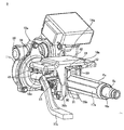
FIG. 1 is a perspective view illustrating a first example of an embodiment of the present invention as seen from the upper front. -
FIG. 2 is a perspective view illustrating the first example as seen from the upper rear. -
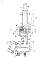
FIG. 3 is a side view of the first example. -
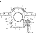
FIG. 4 is a cross-sectional view of section A-A inFIG. 3 . -
FIG. 5 is a cross-sectional view of section B-B inFIG. 3 . -
FIG. 6 is a cross-sectional view of section C-C inFIG. 4 . -
FIG. 7 is an exploded perspective view illustrating the mechanism for adjusting the forward-backward position and the up-down position of the inner column as seen from the upper rear. -
FIG. 8 is a partial cross-sectional view illustrating an example of a conventionally known steering apparatus. -
FIG. 9 is a cross-sectional view of section D-D inFIG. 8 , with part removed. - A first example of an embodiment of the present invention will be explained using
FIG. 1 to FIG. 7 . The steering apparatus for an automobile of this example comprises asteering column 6a, asteering shaft 5a, ahousing 11a for an electricpower steering apparatus 10a, a vehicle-side bracket 19a, an energy-absorbingmember 28 as an attached member and an expansion andcontraction mechanism 29. - In this example, in order to achieve the telescopic mechanism, the
steering column 6a comprises anouter column 18a that is front column, and aninner column 17a that is a rear column, that are combined so as to be capable of relative displacement in the axial direction. Theouter column 18a is formed by using a press to perform punching or bending of a metal plate material such as carbon steel plate having sufficient strength and rigidity, and is formed into a U shape that is open at the top comprising a pair of left and rightside plate sections 30, the inside surface of which face each other, and abottom plate section 31 that is connected to the edges on the bottom ends of theseside plate sections 30. Moreover, both end sections in the width direction of thebottom plate section 31 are inclined at 45 degrees with respect to both the center section in the width direction of the bottom plate section and theside plate sections 30. The dimension in the up-down direction of the side plate sections 30 (height dimension from the edge sections on both ends of the bottom plate section 31) is comparatively large on the rear-end section and comparatively small on the front-end section, and in the portion between the rear-end section and the front-end section, the dimension changes so as to become smaller going toward the front-end side. The bending rigidity of theside plate sections 30 is maintained by forming a plurality of stiffening beads in both the rear-end section and the middle section of theside plate sections 30, and by forming flange sections by bending the top ends of the middle sections 90 degrees toward the outside in the horizontal direction. Furthermore, restraining blocks 32 are fastened to the portion near the top end of the rear-end section of the inside surfaces of theside plate sections 30 by bolts, welding or the like. The bottom surfaces of these restraining blocks 32 are also inclined 45 degrees with respect to theside plate sections 30 and the center section in the width direction of thebottom plate section 31. The portion that is surrounded by the inside surfaces of theside plate sections 30, the top surface of thebottom plate section 31 and the bottom surface of the restraining blocks 32 is such that the center section in the width direction is open toward the top, and forms nearly an octagonal shaped holding space. - The
inner column 17a is formed by performing desired plastic working or milling on the end section of an intermediate material that is integrally formed by extrusion or drawing of a metal material containing a light alloy such as an aluminum alloy, magnesium alloy or the like. The outer perimeter surface of the inner column is an octagonal shape. The front section of thisinner column 17a fits inside the rear section of theouter column 18a such that the forward-backward position is adjustable according to displacement in the axial direction. In other words, of the eight flat surfaces of the outer perimeter surface of theinner column 17a, a pair of left and right surfaces that are parallel with each other come in contact with or closely face the inside surfaces of theside plate sections 30, the three flat surfaces in the center and on both the left and right of the bottom side come in contact with or closely face the top surface of thebottom plate section 31, and the two flat surfaces on the left and right of the top side come in contact with or closely face the bottom surfaces of the retaining blocks 32. In construction that does not comprise a telescopic mechanism, the entire steering column can be formed into an arbitrary column shape, and only the front end section is formed into a U shape that is open at the top end by a pair of left and right side plate sections that face each other and a bottom plate section that connects the edges on the bottom ends of the side plate sections. - Moreover, in construction comprising a telescopic mechanism, the steering
shaft 5a is such that by combining the rear section of theinner shaft 15a on the front side and the front section of theouter shaft 16 on the rear side by a spline fit, theinner shaft 15a and theouter shaft 16a are capable of transmitting rotation force, and are capable of relative displacement in the axial direction. With this construction, the entire length of thesteering shaft 5a is able to expand and contract. The steeringshaft 5a passes through the inside of thesteering column 6a, and the portion near the rear end of theouter shaft 16a is supported by the rear-end section of theinner column 17a by a bearing such as a single-row deep-groove ball bearing that is capable of supporting both radial loads and thrust loads so that steeringshaft 5a can rotate freely. - An
electric motor 14a, which is an auxiliary driving source, is supported on one side of the upper portion of thehousing 11a for the electricpower steering apparatus 10a. Moreover, thehousing 11a houses a plurality of component parts including areduction gear 34 for transmitting the rotation driving force of theelectric motor 14a to thesteering shaft 5a. Furthermore, asupport tube 35 is provided in the left-right direction at the top end section at the front of thehousing 11a. Thehousing 11a is supported by the vehicle body such that it can pivotally displace around a horizontal shaft such as a bolt that is inserted through thesupport tube 35. With this construction, the steeringshaft 5a to which the steering wheel is fastened to the rear-end section, and thesteering column 6a that supports thesteering shaft 5a are able to displace in the up-down direction. Therefore, in construction that does not comprise a tilting mechanism thehousing 11a can be supported by and fastened to the vehicle body by rigid construction. - Moreover, the rear-end section of the
housing 11a is connected and fastened to the front-end section of theouter column 18a. In this example, a connection andfasting section 36 is provided in the center section of the rear-end surface of thehousing 11a, and protrudes toward theouter column 18a side. The outer perimeter surface of this connection andfastening section 36 has a rectangular shaped cross section, and together with being able to be inserted into the front-end section of theouter column 18a through an opening on the top end of the front-end section, as illustrated inFIG. 5 , when inserted inside the front-end section, makes a non-circular fit with the front-end section. The shape of the connection andfastening section 36 can be any arbitrary shape other than a rectangular shape as long as it can be inserted into the front-end section of theouter column 18a and can make a non-circular fit with the front-end section. - In this example, the connection and
fastening section 36 is such that when inserted inside the front-end section of theouter column 18a, the surfaces on the left and right sides of the connection andfastening section 36 come in contact with the inside surfaces of the pair ofside plate sections 30 of theouter column 18a, and the center section in the width direction on the bottom surface of the connection andfastening section 36 comes in contact with the center section in the width direction of thebottom plate section 31 of theouter column 18a. Moreover, throughholes fastening section 36 and theside plate sections 30 that are aligned with each other. Fasteningbolts 39 are inserted through each of the throughholes fastening nuts 40 are screwed onto the tip end sections of thesefastening bolts 39 and tightened. Then, by firmly holding the connection andfastening section 36 and theside plate sections 30 by thehead sections 41 on the base end sections of thefastening bolts 39 and thefastening nuts 40, the connection andfastening section 36 and front-end section of theouter column 18a are connected and fastened together. Furthermore, in this state, the front-end section of theinner shaft 15a is inserted inside thehousing 11a through a center hole in the connection andfastening section 36 and connected to component parts of the electricpower steering apparatus 10a that are housed inside thehousing 11a. - The vehicle-
side bracket 19a comprises atop plate section 42 and a pair of holdingplate sections top plate section 42 and holdingplate sections top plate section 42 and fasten thetop plate section 42 to the vehicle body, are formed in thetop plate section 42. Moreover, holdingplate sections outer column 18a.Long holes plate sections long holes support tube 35. - In this example, an energy-absorbing
member 28, which is a component of theinner column 17a, is attached and fastened to the top surface of the front-end section of theinner column 17a. This energy-absorbing member is formed by bending metal plate, such as mild steel plate that is capable of plastic deformation, into a long rectangular frame shape that is long in the forward-backward direction, and aninstallation plate section 43 protrudes forward from the bottom-end section of the front-end surface thereof. Aninstallation member 44 such as a rivet or screw that is inserted a through hole that is formed in thisinstallation plate section 43 attaches and fastens the energy-absorbingmember 28 to theinner column 17a. This energy-absorbingmember 28 expands due to plastic deformation that occurs during a secondary collision that accompanies a collision accident, and allows theinner column 17a to displace in the forward direction together with the steering wheel. By this means, it is possible to protect the operator by absorbing energy that is transmitted from the body of the operator to theinner column 17a by way of the steering wheel during a secondary collision. - Moreover, the expansion and
contraction mechanism 29 is to expand and contract the distance between the inside surfaces of the holdingplate sections adjustment rod 24a, which is a rod shaped member, anadjustment lever 27a, and a cam device 45. Theadjustment rod 24a is inserted in the left-right direction through thelong holes holes 46 that are formed in theside plate sections 30 andrestraining blocs 32 of theouter column 18a, andlong hole 23a in the forward-backward direction that is long in the axial direction of theinner column 17a and formed in the inside of the energy-absorbing member that is attached to theinner column 17a. Moreover, theadjustment rod 24a is such that ahead section 25a is formed on the base end section (right end section inFIG. 4 andFIG. 7 ), and a convex section that is formed on the inside surface of thishead section 25a fits inside one of thelong holes 22a in the up-down direction that is formed on oneholding plate section 20a of the two holdingplate sections FIG. 4 andFIG. 7 ) so as to be able to displace (move up or down) only along thislong hole 22a in the up-down direction. Furthermore, theadjustment lever 27a is such that the base end section is supported by the tip end section (left end section ofFIG. 4 andFIG. 7 ) of theadjustment rod 24a by way of athrust sliding bearing 47 andnut 48 so that thatadjustment lever 27a can rotate with respect to theadjustment rod 24a, and is prevented from displacement in the removal direction from the tip end section of theadjustment rod 24a. Thelong hole 23a in the forward-backward direction, instead of the energy-absorbing member, can also be formed in theinner column 17a itself, or can be formed in a separate member that is attached to theinner column 17a. - The cam device 45 is provided between the inside surface on the base end section of the
adjustment lever 27a and the outside surface of the other holdingplate section 20b of the two holdingplate sections FIG. 4 andFIG. 7 ). The cam device 45 comprises a drivingcam 49 that is supported by the inside surface of the base end section of theadjustment lever 27a and that rotates together with theadjustment lever 27a, and a drivencam 50 that fits in the otherlong hole 22b in the up-down direction that is formed in the other holdingplate section 20b so as to be able to move only up or down. Cam surfaces are formed on the surfaces of the drivencam 50 and the drivingcam 49 that face each other, and due to relative rotation between the drivencam 50 and drivingcam 49, the dimension in the axial direction of the cam device 45 expands or contracts. In this example, thehead section 25a and the drivencam 50 form a pair of pressing sections. Spacers 51a, 51b, which are formed using a material such as synthetic resin that slides easily, are placed over positions in the middle section of theadjustment rod 24a that are located on the inside of thelong holes adjustment rod 24a to smoothly displace along thelong holes spacer 51b that fits in the otherlong hole 22b in the up-down direction, by engaging with the drivencam 50, prevents rotation of the drivencam 50. Furthermore, a cylindricalradial sliding bearing 52 that is made using a material that slides easily is located between the inner circumferential surface of the drivingcam 49 and the outer circumferential surface of theadjustment rod 24a. - In the case of the steering apparatus of this example, when adjusting the up-down position or the forward-backward position of the steering wheel (not illustrated in the figure) that is fastened to the rear-end section of the
steering shaft 5a, the dimension in the axial direction of the cam device 45 is shortened by rotating theadjustment lever 27a in the downward direction. As a result, the distance between the inside surfaces of the holdingplate sections plate sections side plate sections 30 of theouter column 18a is sufficiently reduced. At the same time, the distance between theside plate sections 30 and the restraining blocks 32 is expanded, and the surface pressure at the area of contact between the outer circumferential surface of theinner column 17 and inner circumferential surface of theouter column 18a is sufficiently reduced. As a result, the state of theouter column 18a andinner column 17a being fastened to the vehicle-side bracket 19a is released. When the up-down position of the steering wheel is adjusted in this state, thesteering column 6a and thesteering shaft 5a are pivoted around thesupport tube 35 within the range that theadjustment rod 24a can displace inside thelong holes steering column 6a and thesteering shaft 5a is extended or contracted within the range that theadjustment rod 24a can displace in thelong hole 23a in the forward-backward direction. After adjustment, by rotating theadjustment lever 27a in the upward direction, the dimension in the axial direction of the cam device 45 is expanded. As a result, due to an operation that is opposite that when releasing the fastened state above, the surface pressure at the areas of contact is sufficiently increased. Consequently, the steering wheel is maintained at the adjusted position. - Moreover, in this example, construction is provided for increasing the support strength for supporting the steering wheel in the adjusted up-down position. In other words, the base section of a
pivot arm 53 is fitted over the portion of theadjustment rod 24a near the tip end of the middle section so as to be able to pivot and displace. Moreover, amale gear 54 is provided on the tip end section of thepivot arm 53 and afemale gear 55 is provided on part of the outside surface of the holdingplate section 20b, and as thepivot arm 53 pivots, themale gear 54 andfemale gear 55 can be placed in either the engaged state or released state. As theadjustment lever 27a is rotated in a direction for adjusting the position of the steering wheel, thepivot arm 53 is pivoted in a direction that releases the engagement between themale gear 54 and thefemale gear 55. When themale gear 54 and thefemale gear 55 are in the engaged state, theadjustment rod 24a is connected with the holdingplate section 20b by way of thepivot arm 53, so regardless of whether there is a large impact load during a secondary collision, the up-down position of the steering wheel does not move a large amount. - The driven
cam 50 is assembled to the base section of thepivot arm 53 so as to be able to rotate relative to thepivot arm 53 as well as to be able to displace a little in the up-down direction with respect to thepivot arm 53. The drivencam 50, as described above, is such that relative rotation with respect to the holdingplate section 20b is prevented. Moreover, a restoringspring 56 is provided between the drivencam 50 and thepivot arm 53 such that the drivencam 50 is supported on thepivot arm 53 so as to be able move up or down a little about a neutral position. The reason for allowing this small amount of up or down movement is that, even though the up-down position of the steering wheel can be adjusted in a smooth non-step manner, the engagement position between themale gear 54 andfemale gear 55 is in steps, so this small amount of up or down movement absorbs that difference. - With the steering apparatus of this example, it is possible to make the assembly direction of the
steering column 6a in the vehicle-side bracket 19a coincide with the assembly direction of thesteering column 6a in thehousing 11a. In other words, when assembling thesteering column 6a into the vehicle-side bracket 19a, the middle portion of thesteering column 6a (rear-end section of theouter column 18a) is inserted between the pair of holdingplate sections side bracket 19a from the bottom end edge side of these holdingplate sections steering column 6a with respect to the vehicle-side bracket 19a is in the radial direction of thesteering column 6a (direction from the bottom surface toward the top surface). On the other hand, when assembling thesteering column 6a in thehousing 11a, the connection andfastening section 36 that is provided on the rear-end section of thehousing 11a is inserted into the front-end section of thesteering column 6a (front-end section of theouter column 18a) from an opening on the top end of this front-end section. That is, the assembly direction of thesteering column 6a with respect to thehousing 11a can also be in the radial direction of thesteering column 6a (direction from the bottom surface toward the top surface). - Therefore, when assembling the steering apparatus of this example, the
housing 11a and the vehicle-side bracket 19a are set in a holding tool with the positional relationship illustrated inFIG. 6 , and in this state, the front-end section and the middle section of thesteering column 6a can be assembled into the connection andfastening section 36 of thehousing 11a and the pair of holdingplate sections side bracket 19a in the radial direction of thesteering column 6a from the bottom inFIG. 6 . Therefore, assembling thesteering column 6a in the vehicle-side support bracket 19a and assembling thesteering column 6a in thehousing 11a can be performed in one process, and thus it is possible to improve the ease of assembly of the steering apparatus by that amount. The actual work is performed in the positional relationship of up-and-down is opposite from the positional relationship illustrated inFIG. 6 . - The work of inserting the connection and
fastening section 36 inside the front-end section of thesteering column 6a, and the work of inserting the middle section of thesteering column 6a into the portion between the holdingplate sections housing 11a and the vehicle-side support bracket 19a are set in a holding tool with the positional relationship illustrated inFIG. 6 , and then only thehousing 11a is pivoted and displaced around thesupport tube 35 toward the bottom inFIG. 6 . Then, in this state, the connection andfastening section 36 is inserted inside the front-end section of thesteering column 6a through opening in the top ends of the front-end section. After that, thehousing 11a and thesteering column 6a are pivoted and displaced around thesupport tube 35 toward the top inFIG. 6 , and the middle section of thesteering column 6a is inserted into the portion between the holdingplate sections steering column 6a is in the proper phase, and this proper phase is maintained, so it becomes easy to perform the following insertion work. In this case as well, the two insertions described above can be performed in one process on an assembly line for the steering apparatus. - In either case, in this example, the work of inserting the connection and
fastening section 36 inside the front-end section of thesteering column 6a through an opening on the top ends of the front-end section is performed in a state wherein thesteering shaft 5a is not placed inside thesteering column 6a, or is performed in a state wherein the front-end section of the steering shaft that has been placed inside thesteering column 6a is moved sufficiently out of the way toward the rear. In this way, the front-end section of thesteering shaft 5a is prevented from hindering the insertion work. - In the case of the steering apparatus of this example, the connection and
fastening section 36 and theside plate sections 30 are fastened together at the portion near an opening on the top end of the side plate sections 30 (opposite side from the bottom plate section 31) by fasteningbolts 39, so theside plate sections 30 bend or bow and are firmly tightened to the connection andfastening section 36. Similarly, the expansion andcontraction mechanism 29 is also constructed so as to be inserted into throughholes 46 that are formed in portions near the top end of theside plate sections 30, so in the fastened state, theside plate sections 30 bend or bow, so the tightening force by this expansion andcontraction mechanism 29 is tight with respect to thesteering column 6a. Furthermore, the insertion direction of theadjustment rod 24a through the throughholes 46, and the insertion direction of thefastening bolts 39 through the throughholes holes fastening bolts 39 andfastening nuts 40 that is used for connecting and fastening the connection andfastening section 36 and the front-end section of thesteering column 6a is provided at two locations that are separated in the forward-backward direction. Therefore, it is possible to sufficiently maintain the bending rigidity of the connecting section between the connection andfastening section 36 and the front-end section of thesteering column 6a. - In the embodiment of the present invention described above, the present invention is applied to construction that comprises both a tilt mechanism for making it possible to adjust the up-down position of the steering wheel, and a telescopic mechanism for making it possible to adjust the forward-backward position of the steering wheel. However, the present invention can also be applied to construction that comprises only one of these mechanisms.
-
- 1
- Steering wheel
- 2
- Steering gear unit
- 3
- Input shaft
- 4
- Tie rod
- 5, 5a
- Steering shaft
- 6, 6a
- Steering column
- 7
- Universal joint
- 8
- Intermediate shaft
- 9
- Universal joint
- 10, 10a
- Electric power steering apparatus
- 11, 11a
- Housing
- 12
- Vehicle body
- 13
- Horizontal shaft
- 14, 14a
- Electric motor
- 15, 15a
- Inner shaft
- 16, 16a
- Outer shaft
- 17, 17a
- Inner column
- 18, 18a
- Outer column
- 19, 19a
- Vehicle-side bracket
- 20, 20a, 20b
- Holding plate section
- 21, 21a
- Column-side bracket
- 22, 22a, 22b
- Long hole in the up-down direction
- 23, 23a
- Long hole in the forward-backward direction
- 24, 24a
- Adjustment rod
- 25, 25a
- Head section
- 26
- Adjustment nut
- 27, 27a
- Adjustment lever
- 28
- Energy absorbing member
- 29
- Expansion and contraction mechanism
- 30
- Side plate section
- 31
- Bottom plate section
- 32
- Retaining block
- 33
- Bearing
- 34
- Reduction gear
- 35
- Support tube
- 36
- Connection and fastening section
- 37
- Through hole
- 38
- Through hole
- 39
- Fastening bolt
- 40
- Fastening nut
- 41
- Head section
- 42
- Top plate section
- 43
- Installation plate section
- 44
- Installation member
- 45
- Cam device
- 46
- Through hole
- 47
- Thrust sliding bearing
- 48
- Nut
- 49
- Driving cam
- 50
- Driven cam
- 51a, 51b
- Spacer
- 52
- Radial sliding bearing
- 53
- Pivot arm
- 54
- Male gear
- 55
- Female gear
- 56
- Restoring spring
Claims (7)
- A steering apparatus for an automobile comprising:a steering column having a front-end section that is formed in a U shape that is open at the top and comprises a pair of left and right side plate sections that face each other and a bottom plate section that connects to the edges on the bottom ends of these side plate sections;a housing for an electric power steering apparatus that is supported by the vehicle body and that has a connection and fastening section on the rear that is capable of being inserted inside the front-end section of the steering column through an opening in the top end of the front-end section, and when inserted inside the front-end section is capable of a non-circular fit in the front-end section;a vehicle-side bracket that is supported by the vehicle body and that has a pair of holding plate sections that are located at positions on both the left and right sides of the middle section of the steering column, with the portion between the edges on bottom edges being open; andan expansion and contraction mechanism that comprises a rod shaped member that is inserted in the left-right direction through through holes that are formed in positions of the holding plate sections that are aligned with each other, and a pair of pressing sections that are provided on both end sections of the rod shaped member, and by moving these pressing sections away from each other or close to each other in the axial direction of the rod shape member, the distance between the holding plate sections is changed, and when this space is contracted, the expansion and contraction mechanism fastens the steering column to these holding plate sections, andwith the connection and fastening section being fitted with a non-circular fit inside the front-end section, the connection and fastening section and the front-end section of the steering column being connected and fastened together by a bolt.
- The steering apparatus according to claim 1, wherein through holes in the left-right direction are formed at positions in the side plate sections of the front-end section of the steering column and in the connection and fastening section of the housing that are aligned with each other; and together with inserting a bolt through these through holes that are formed in the side plate sections and the connection and fastening section, a nut is screwed on the tip end section of the bolt.
- The steering apparatus according to claim 2, wherein more than one set of the through holes is formed in the side plate sections and the connection and fastening section, and together with inserting a bolt through each of the through holes, a nut is screwed on the tip end section of the bolt.
- The steering apparatus for an automobile according to claim 1, wherein
the housing is supported by the vehicle body so as to be able to pivotally displace around a horizontal shaft that is arranged in the left-right direction;
the through holes in the holding plate sections are long holes in the up-down direction that are arc shaped around the center of the horizontal shaft;
a through hole is formed in the middle section of the steering column at a position that is aligned with the long holes in the up-down direction;
the rod member is inserted through the long holes in the up-down direction of the housing and the through hole of the steering column; and
when the fastened state of the steering column being fastened to the holding plate sections is released by enlarging the distance between the holding plate sections by the expansion and contraction mechanism, the up-down position of the steering column can be adjusted within the range that the rod shaped member can displace in the long holes in the up-down direction. - The steering apparatus for an automobile according to claim 1 wherein
the steering column comprises a front column that is located the front side, and a rear column that is located on the rear side and assembled so as to be able to displace relative to the front column;
the front-end section is formed on the front column;
a through hole is formed in the rear section of the front column at a position that is aligned with the through holes in the holding plate sections;
a long hole in the forward-backward direction that is long in the axial direction of the rear column is formed in the rear column at a position that is aligned with the through holes in the holding plate sections and the through hole in the front column;
the rod shaped member is inserted through the through holes in the holding plate sections, the through hole in the front column and the long hole in the forward-backward direction of the rear column; and
when the fastened state of the rear column being fastened to the holding plate sections and the front column is released by enlarging the distance between the holding plate sections by the expansion and contraction mechanism, it is possible to adjust the forward-backward position of the rear column within a range that the rod shaped member can displace inside the long hole in the forward-backward direction. - The steering apparatus for an automobile according to claim 5, wherein
the front column is an outer column, and the entire outer column has side plate sections and a bottom plate section, forming a U shape that is open at the top;
the rear column is an inner column and is such that the front section of the inner column fits inside the rear section of the outer column;
the expansion and contraction mechanism expands or contracts the inner dimension of the rear section of the outer column by changing the distance between the holding plate sections, such that when the inner dimension is contracted, displacement in the axial direction of the inner column with respect to the outer column is suppressed, and when the inner dimension is expanded, displacement in the axial direction of the inner column with respect to the outer column is possible. - The steering apparatus for an automobile according to claim 6, wherein
through holes in the left-right direction are formed at positions in the side plate sections of the outer column and in the connection and fastening section of the housing that are aligned with each other; and together with inserting a bolt through these through holes that are formed in the side plate sections and the connection and fastening section, a nut is screwed on the tip end section of the bolt, and
the through holes that are formed in the side plate section through which the bolt is inserted, and the through holes that are formed in the rear section of the side plate sections through which the rod shaped member is inserted are formed in portions near the openings on the top end of the side plate sections.
Applications Claiming Priority (2)
| Application Number | Priority Date | Filing Date | Title |
|---|---|---|---|
| JP2011111582 | 2011-05-18 | ||
| PCT/JP2012/062651 WO2012157703A1 (en) | 2011-05-18 | 2012-05-17 | Steering apparatus for motor vehicle |
Publications (3)
| Publication Number | Publication Date |
|---|---|
| EP2712771A1 true EP2712771A1 (en) | 2014-04-02 |
| EP2712771A4 EP2712771A4 (en) | 2014-12-03 |
| EP2712771B1 EP2712771B1 (en) | 2018-03-28 |
Family
ID=47177020
Family Applications (1)
| Application Number | Title | Priority Date | Filing Date |
|---|---|---|---|
| EP12733397.9A Not-in-force EP2712771B1 (en) | 2011-05-18 | 2012-05-17 | Steering apparatus for motor vehicle |
Country Status (5)
| Country | Link |
|---|---|
| US (1) | US9073567B2 (en) |
| EP (1) | EP2712771B1 (en) |
| JP (2) | JP5614449B2 (en) |
| CN (1) | CN102933448B (en) |
| WO (1) | WO2012157703A1 (en) |
Families Citing this family (26)
| Publication number | Priority date | Publication date | Assignee | Title |
|---|---|---|---|---|
| GB201110277D0 (en) * | 2011-06-17 | 2011-08-03 | Trw Ltd | A clamp assembly for a steering column assembly |
| EP2899096B1 (en) * | 2013-01-15 | 2017-07-26 | NSK Ltd. | Tilt-type steering device |
| DE102014102661B3 (en) * | 2014-02-28 | 2015-04-02 | Thyssenkrupp Presta Ag | Steering column for a motor vehicle |
| FR3029489B1 (en) * | 2014-12-09 | 2018-06-15 | Zf Systemes De Direction Nacam S.A.S. | ADJUSTABLE STEERING COLUMN MECHANISM IN DEPTH WITH RETRACTABLE ROD |
| USD772125S1 (en) * | 2015-01-21 | 2016-11-22 | Rotatech International Corp. | Electric power steering |
| US10351159B2 (en) | 2015-05-01 | 2019-07-16 | Steering Solutions Ip Holding Corporation | Retractable steering column with a radially projecting attachment |
| US11560169B2 (en) | 2015-06-11 | 2023-01-24 | Steering Solutions Ip Holding Corporation | Retractable steering column system and method |
| US10343706B2 (en) | 2015-06-11 | 2019-07-09 | Steering Solutions Ip Holding Corporation | Retractable steering column system, vehicle having the same, and method |
| CN106256651B (en) | 2015-06-16 | 2019-06-04 | 操纵技术Ip控股公司 | Retractable steering column assembly and method |
| US9828016B2 (en) | 2015-06-24 | 2017-11-28 | Steering Solutions Ip Holding Corporation | Retractable steering column system, vehicle having the same, and method |
| DE102016111473A1 (en) | 2015-06-25 | 2016-12-29 | Steering Solutions Ip Holding Corporation | STATIONARY STEERING WHEEL ASSEMBLY AND METHOD |
| US9840271B2 (en) * | 2015-06-29 | 2017-12-12 | Steering Solutions Ip Holding Corporation | Retractable steering column with rake limiter |
| US9849904B2 (en) | 2015-07-31 | 2017-12-26 | Steering Solutions Ip Holding Corporation | Retractable steering column with dual actuators |
| US9809155B2 (en) | 2015-10-27 | 2017-11-07 | Steering Solutions Ip Holding Corporation | Retractable steering column assembly having lever, vehicle having retractable steering column assembly, and method |
| CN107521547B (en) | 2016-06-21 | 2020-03-10 | 操纵技术Ip控股公司 | Self-locking telescopic actuator for steering column assembly |
| US10457313B2 (en) | 2016-06-28 | 2019-10-29 | Steering Solutions Ip Holding Corporation | ADAS wheel locking device |
| US10363958B2 (en) | 2016-07-26 | 2019-07-30 | Steering Solutions Ip Holding Corporation | Electric power steering mode determination and transitioning |
| DE102016114678A1 (en) * | 2016-08-08 | 2018-02-08 | Thyssenkrupp Ag | Rotary bearing arrangement for a steering column of a motor vehicle |
| US10189496B2 (en) | 2016-08-22 | 2019-01-29 | Steering Solutions Ip Holding Corporation | Steering assembly having a telescope drive lock assembly |
| US10351160B2 (en) | 2016-11-30 | 2019-07-16 | Steering Solutions Ip Holding Corporation | Steering column assembly having a sensor assembly |
| US10370022B2 (en) | 2017-02-13 | 2019-08-06 | Steering Solutions Ip Holding Corporation | Steering column assembly for autonomous vehicle |
| US10385930B2 (en) | 2017-02-21 | 2019-08-20 | Steering Solutions Ip Holding Corporation | Ball coupling assembly for steering column assembly |
| CN109131530B (en) * | 2018-07-31 | 2020-10-27 | 浙江镭众科技有限公司 | Dual-mode directional control device and new energy vehicle |
| US10974756B2 (en) | 2018-07-31 | 2021-04-13 | Steering Solutions Ip Holding Corporation | Clutch device latching system and method |
| JP2019142500A (en) * | 2019-04-24 | 2019-08-29 | 日本精工株式会社 | Steering apparatus |
| WO2025239004A1 (en) * | 2024-05-14 | 2025-11-20 | 株式会社山田製作所 | Steering device |
Family Cites Families (19)
| Publication number | Priority date | Publication date | Assignee | Title |
|---|---|---|---|---|
| JP3763337B2 (en) | 1998-09-16 | 2006-04-05 | 株式会社ジェイテクト | Electric steering device |
| JP3725762B2 (en) | 2000-05-25 | 2005-12-14 | 光洋精工株式会社 | Shock absorbing electric power steering system |
| JP2002302046A (en) * | 2001-04-09 | 2002-10-15 | Koyo Seiko Co Ltd | Steering device |
| EP1438223B1 (en) * | 2001-10-23 | 2006-06-07 | TRW Lucas Varity Electric Steering Limited | A vehicle steering assembly |
| JP4069362B2 (en) * | 2002-07-05 | 2008-04-02 | 日本精工株式会社 | Steering column device |
| EP1547901B1 (en) * | 2002-07-08 | 2011-03-23 | Nsk Ltd. | Electric power steering device |
| JP4716679B2 (en) * | 2003-06-25 | 2011-07-06 | 日本精工株式会社 | Worm speed reducer and electric power steering device |
| US7055647B2 (en) | 2004-07-02 | 2006-06-06 | Nacam France Sa | Electrically-assisted steering mechanism for vehicles |
| JP2006111064A (en) * | 2004-10-13 | 2006-04-27 | Nsk Ltd | Steering device |
| US7384068B2 (en) * | 2004-12-03 | 2008-06-10 | Delphi Technologies, Inc. | Snap in tilt bumper |
| US20060230863A1 (en) * | 2005-04-19 | 2006-10-19 | Delphi Technologies, Inc. | Steering column with rake and telescope adjustment |
| DE102005034952B3 (en) * | 2005-07-22 | 2007-02-22 | Thyssenkrupp Automotive Ag | Adjustable steering column for a motor vehicle |
| US7699344B2 (en) * | 2006-02-21 | 2010-04-20 | Nsk Ltd. | Steering device |
| JP2008087583A (en) * | 2006-09-29 | 2008-04-17 | Nsk Ltd | Steering device and method for assembling steering device |
| JP5092880B2 (en) * | 2007-05-17 | 2012-12-05 | 日本精工株式会社 | Steering device |
| JP4640435B2 (en) * | 2008-04-11 | 2011-03-02 | 日本精工株式会社 | Steering device |
| JP2011046309A (en) * | 2009-08-27 | 2011-03-10 | Jtekt Corp | Steering device for vehicle |
| JP5528868B2 (en) * | 2010-03-19 | 2014-06-25 | 株式会社ジェイテクト | Steering device |
| JP5293824B2 (en) * | 2010-08-05 | 2013-09-18 | 日本精工株式会社 | Shock absorbing steering device |
-
2012
- 2012-05-17 US US13/522,816 patent/US9073567B2/en active Active
- 2012-05-17 JP JP2012523763A patent/JP5614449B2/en active Active
- 2012-05-17 CN CN201280000343.7A patent/CN102933448B/en active Active
- 2012-05-17 EP EP12733397.9A patent/EP2712771B1/en not_active Not-in-force
- 2012-05-17 WO PCT/JP2012/062651 patent/WO2012157703A1/en not_active Ceased
-
2014
- 2014-09-09 JP JP2014183515A patent/JP5850115B2/en active Active
Also Published As
| Publication number | Publication date |
|---|---|
| JPWO2012157703A1 (en) | 2014-07-31 |
| EP2712771B1 (en) | 2018-03-28 |
| WO2012157703A1 (en) | 2012-11-22 |
| EP2712771A4 (en) | 2014-12-03 |
| CN102933448A (en) | 2013-02-13 |
| CN102933448B (en) | 2015-12-09 |
| US20130199866A1 (en) | 2013-08-08 |
| US9073567B2 (en) | 2015-07-07 |
| JP5614449B2 (en) | 2014-10-29 |
| JP5850115B2 (en) | 2016-02-03 |
| JP2014223917A (en) | 2014-12-04 |
Similar Documents
| Publication | Publication Date | Title |
|---|---|---|
| EP2712771B1 (en) | Steering apparatus for motor vehicle | |
| EP2711264B1 (en) | Steering apparatus for motor vehicle | |
| US20070068311A1 (en) | Steering apparatus | |
| EP2982567B1 (en) | Telescopic steering device and outer column | |
| EP2692610B1 (en) | Steering column device | |
| EP2602170B1 (en) | Steering apparatus | |
| EP2749474B1 (en) | Support bracket, method for manufacturing support bracket, and electric power steering device using support bracket | |
| JP5076673B2 (en) | Steering device | |
| JP5229280B2 (en) | Shock absorbing steering device | |
| EP1640241B1 (en) | Steering apparatus | |
| WO2014030713A1 (en) | Telescopic steering device | |
| EP2765058A1 (en) | Steering column device | |
| JP2011168244A (en) | Steering column device and assembling method thereof | |
| JP5082871B2 (en) | Vehicle steering device | |
| JP5146407B2 (en) | Steering device | |
| JP5034490B2 (en) | Shock absorbing steering column device | |
| JP2014104782A (en) | Support device for steering column |
Legal Events
| Date | Code | Title | Description |
|---|---|---|---|
| PUAI | Public reference made under article 153(3) epc to a published international application that has entered the european phase |
Free format text: ORIGINAL CODE: 0009012 |
|
| 17P | Request for examination filed |
Effective date: 20120718 |
|
| AK | Designated contracting states |
Kind code of ref document: A1 Designated state(s): AL AT BE BG CH CY CZ DE DK EE ES FI FR GB GR HR HU IE IS IT LI LT LU LV MC MK MT NL NO PL PT RO RS SE SI SK SM TR |
|
| DAX | Request for extension of the european patent (deleted) | ||
| A4 | Supplementary search report drawn up and despatched |
Effective date: 20141104 |
|
| RIC1 | Information provided on ipc code assigned before grant |
Ipc: B62D 5/04 20060101ALI20141029BHEP Ipc: B62D 1/184 20060101ALI20141029BHEP Ipc: B60R 25/00 20130101AFI20141029BHEP Ipc: B60R 25/10 20130101ALI20141029BHEP Ipc: B62D 1/16 20060101ALI20141029BHEP Ipc: E05B 49/00 20060101ALI20141029BHEP |
|
| STAA | Information on the status of an ep patent application or granted ep patent |
Free format text: STATUS: EXAMINATION IS IN PROGRESS |
|
| 17Q | First examination report despatched |
Effective date: 20161129 |
|
| RIC1 | Information provided on ipc code assigned before grant |
Ipc: B62D 1/16 20060101ALI20170831BHEP Ipc: B62D 1/187 20060101ALI20170831BHEP Ipc: B60R 25/00 20130101AFI20170831BHEP Ipc: E05B 49/00 20060101ALI20170831BHEP Ipc: B62D 5/04 20060101ALI20170831BHEP Ipc: B62D 1/184 20060101ALI20170831BHEP Ipc: B60R 25/10 20130101ALI20170831BHEP |
|
| GRAP | Despatch of communication of intention to grant a patent |
Free format text: ORIGINAL CODE: EPIDOSNIGR1 |
|
| STAA | Information on the status of an ep patent application or granted ep patent |
Free format text: STATUS: GRANT OF PATENT IS INTENDED |
|
| INTG | Intention to grant announced |
Effective date: 20171013 |
|
| GRAS | Grant fee paid |
Free format text: ORIGINAL CODE: EPIDOSNIGR3 |
|
| GRAA | (expected) grant |
Free format text: ORIGINAL CODE: 0009210 |
|
| STAA | Information on the status of an ep patent application or granted ep patent |
Free format text: STATUS: THE PATENT HAS BEEN GRANTED |
|
| AK | Designated contracting states |
Kind code of ref document: B1 Designated state(s): AL AT BE BG CH CY CZ DE DK EE ES FI FR GB GR HR HU IE IS IT LI LT LU LV MC MK MT NL NO PL PT RO RS SE SI SK SM TR |
|
| REG | Reference to a national code |
Ref country code: GB Ref legal event code: FG4D |
|
| REG | Reference to a national code |
Ref country code: CH Ref legal event code: EP |
|
| REG | Reference to a national code |
Ref country code: AT Ref legal event code: REF Ref document number: 983117 Country of ref document: AT Kind code of ref document: T Effective date: 20180415 |
|
| REG | Reference to a national code |
Ref country code: IE Ref legal event code: FG4D |
|
| REG | Reference to a national code |
Ref country code: DE Ref legal event code: R096 Ref document number: 602012044477 Country of ref document: DE |
|
| REG | Reference to a national code |
Ref country code: FR Ref legal event code: PLFP Year of fee payment: 7 |
|
| PG25 | Lapsed in a contracting state [announced via postgrant information from national office to epo] |
Ref country code: LT Free format text: LAPSE BECAUSE OF FAILURE TO SUBMIT A TRANSLATION OF THE DESCRIPTION OR TO PAY THE FEE WITHIN THE PRESCRIBED TIME-LIMIT Effective date: 20180328 Ref country code: HR Free format text: LAPSE BECAUSE OF FAILURE TO SUBMIT A TRANSLATION OF THE DESCRIPTION OR TO PAY THE FEE WITHIN THE PRESCRIBED TIME-LIMIT Effective date: 20180328 Ref country code: NO Free format text: LAPSE BECAUSE OF FAILURE TO SUBMIT A TRANSLATION OF THE DESCRIPTION OR TO PAY THE FEE WITHIN THE PRESCRIBED TIME-LIMIT Effective date: 20180628 Ref country code: FI Free format text: LAPSE BECAUSE OF FAILURE TO SUBMIT A TRANSLATION OF THE DESCRIPTION OR TO PAY THE FEE WITHIN THE PRESCRIBED TIME-LIMIT Effective date: 20180328 |
|
| REG | Reference to a national code |
Ref country code: NL Ref legal event code: MP Effective date: 20180328 |
|
| REG | Reference to a national code |
Ref country code: LT Ref legal event code: MG4D |
|
| PG25 | Lapsed in a contracting state [announced via postgrant information from national office to epo] |
Ref country code: LV Free format text: LAPSE BECAUSE OF FAILURE TO SUBMIT A TRANSLATION OF THE DESCRIPTION OR TO PAY THE FEE WITHIN THE PRESCRIBED TIME-LIMIT Effective date: 20180328 Ref country code: SE Free format text: LAPSE BECAUSE OF FAILURE TO SUBMIT A TRANSLATION OF THE DESCRIPTION OR TO PAY THE FEE WITHIN THE PRESCRIBED TIME-LIMIT Effective date: 20180328 Ref country code: GR Free format text: LAPSE BECAUSE OF FAILURE TO SUBMIT A TRANSLATION OF THE DESCRIPTION OR TO PAY THE FEE WITHIN THE PRESCRIBED TIME-LIMIT Effective date: 20180629 Ref country code: BG Free format text: LAPSE BECAUSE OF FAILURE TO SUBMIT A TRANSLATION OF THE DESCRIPTION OR TO PAY THE FEE WITHIN THE PRESCRIBED TIME-LIMIT Effective date: 20180628 Ref country code: RS Free format text: LAPSE BECAUSE OF FAILURE TO SUBMIT A TRANSLATION OF THE DESCRIPTION OR TO PAY THE FEE WITHIN THE PRESCRIBED TIME-LIMIT Effective date: 20180328 |
|
| PG25 | Lapsed in a contracting state [announced via postgrant information from national office to epo] |
Ref country code: IT Free format text: LAPSE BECAUSE OF FAILURE TO SUBMIT A TRANSLATION OF THE DESCRIPTION OR TO PAY THE FEE WITHIN THE PRESCRIBED TIME-LIMIT Effective date: 20180328 Ref country code: AL Free format text: LAPSE BECAUSE OF FAILURE TO SUBMIT A TRANSLATION OF THE DESCRIPTION OR TO PAY THE FEE WITHIN THE PRESCRIBED TIME-LIMIT Effective date: 20180328 Ref country code: PL Free format text: LAPSE BECAUSE OF FAILURE TO SUBMIT A TRANSLATION OF THE DESCRIPTION OR TO PAY THE FEE WITHIN THE PRESCRIBED TIME-LIMIT Effective date: 20180328 Ref country code: EE Free format text: LAPSE BECAUSE OF FAILURE TO SUBMIT A TRANSLATION OF THE DESCRIPTION OR TO PAY THE FEE WITHIN THE PRESCRIBED TIME-LIMIT Effective date: 20180328 Ref country code: ES Free format text: LAPSE BECAUSE OF FAILURE TO SUBMIT A TRANSLATION OF THE DESCRIPTION OR TO PAY THE FEE WITHIN THE PRESCRIBED TIME-LIMIT Effective date: 20180328 Ref country code: RO Free format text: LAPSE BECAUSE OF FAILURE TO SUBMIT A TRANSLATION OF THE DESCRIPTION OR TO PAY THE FEE WITHIN THE PRESCRIBED TIME-LIMIT Effective date: 20180328 Ref country code: NL Free format text: LAPSE BECAUSE OF FAILURE TO SUBMIT A TRANSLATION OF THE DESCRIPTION OR TO PAY THE FEE WITHIN THE PRESCRIBED TIME-LIMIT Effective date: 20180328 |
|
| PG25 | Lapsed in a contracting state [announced via postgrant information from national office to epo] |
Ref country code: SM Free format text: LAPSE BECAUSE OF FAILURE TO SUBMIT A TRANSLATION OF THE DESCRIPTION OR TO PAY THE FEE WITHIN THE PRESCRIBED TIME-LIMIT Effective date: 20180328 Ref country code: CZ Free format text: LAPSE BECAUSE OF FAILURE TO SUBMIT A TRANSLATION OF THE DESCRIPTION OR TO PAY THE FEE WITHIN THE PRESCRIBED TIME-LIMIT Effective date: 20180328 Ref country code: SK Free format text: LAPSE BECAUSE OF FAILURE TO SUBMIT A TRANSLATION OF THE DESCRIPTION OR TO PAY THE FEE WITHIN THE PRESCRIBED TIME-LIMIT Effective date: 20180328 |
|
| REG | Reference to a national code |
Ref country code: CH Ref legal event code: PL |
|
| REG | Reference to a national code |
Ref country code: AT Ref legal event code: MK05 Ref document number: 983117 Country of ref document: AT Kind code of ref document: T Effective date: 20180328 |
|
| PG25 | Lapsed in a contracting state [announced via postgrant information from national office to epo] |
Ref country code: PT Free format text: LAPSE BECAUSE OF FAILURE TO SUBMIT A TRANSLATION OF THE DESCRIPTION OR TO PAY THE FEE WITHIN THE PRESCRIBED TIME-LIMIT Effective date: 20180730 |
|
| REG | Reference to a national code |
Ref country code: DE Ref legal event code: R097 Ref document number: 602012044477 Country of ref document: DE |
|
| REG | Reference to a national code |
Ref country code: BE Ref legal event code: MM Effective date: 20180531 |
|
| PG25 | Lapsed in a contracting state [announced via postgrant information from national office to epo] |
Ref country code: AT Free format text: LAPSE BECAUSE OF FAILURE TO SUBMIT A TRANSLATION OF THE DESCRIPTION OR TO PAY THE FEE WITHIN THE PRESCRIBED TIME-LIMIT Effective date: 20180328 Ref country code: DK Free format text: LAPSE BECAUSE OF FAILURE TO SUBMIT A TRANSLATION OF THE DESCRIPTION OR TO PAY THE FEE WITHIN THE PRESCRIBED TIME-LIMIT Effective date: 20180328 Ref country code: MC Free format text: LAPSE BECAUSE OF FAILURE TO SUBMIT A TRANSLATION OF THE DESCRIPTION OR TO PAY THE FEE WITHIN THE PRESCRIBED TIME-LIMIT Effective date: 20180328 |
|
| PLBE | No opposition filed within time limit |
Free format text: ORIGINAL CODE: 0009261 |
|
| STAA | Information on the status of an ep patent application or granted ep patent |
Free format text: STATUS: NO OPPOSITION FILED WITHIN TIME LIMIT |
|
| REG | Reference to a national code |
Ref country code: IE Ref legal event code: MM4A |
|
| PG25 | Lapsed in a contracting state [announced via postgrant information from national office to epo] |
Ref country code: CH Free format text: LAPSE BECAUSE OF NON-PAYMENT OF DUE FEES Effective date: 20180531 Ref country code: LI Free format text: LAPSE BECAUSE OF NON-PAYMENT OF DUE FEES Effective date: 20180531 |
|
| 26N | No opposition filed |
Effective date: 20190103 |
|
| PG25 | Lapsed in a contracting state [announced via postgrant information from national office to epo] |
Ref country code: LU Free format text: LAPSE BECAUSE OF NON-PAYMENT OF DUE FEES Effective date: 20180517 |
|
| PG25 | Lapsed in a contracting state [announced via postgrant information from national office to epo] |
Ref country code: IE Free format text: LAPSE BECAUSE OF NON-PAYMENT OF DUE FEES Effective date: 20180517 |
|
| PG25 | Lapsed in a contracting state [announced via postgrant information from national office to epo] |
Ref country code: BE Free format text: LAPSE BECAUSE OF NON-PAYMENT OF DUE FEES Effective date: 20180531 Ref country code: SI Free format text: LAPSE BECAUSE OF FAILURE TO SUBMIT A TRANSLATION OF THE DESCRIPTION OR TO PAY THE FEE WITHIN THE PRESCRIBED TIME-LIMIT Effective date: 20180328 |
|
| PG25 | Lapsed in a contracting state [announced via postgrant information from national office to epo] |
Ref country code: MT Free format text: LAPSE BECAUSE OF NON-PAYMENT OF DUE FEES Effective date: 20180517 |
|
| PG25 | Lapsed in a contracting state [announced via postgrant information from national office to epo] |
Ref country code: TR Free format text: LAPSE BECAUSE OF FAILURE TO SUBMIT A TRANSLATION OF THE DESCRIPTION OR TO PAY THE FEE WITHIN THE PRESCRIBED TIME-LIMIT Effective date: 20180328 |
|
| PG25 | Lapsed in a contracting state [announced via postgrant information from national office to epo] |
Ref country code: HU Free format text: LAPSE BECAUSE OF FAILURE TO SUBMIT A TRANSLATION OF THE DESCRIPTION OR TO PAY THE FEE WITHIN THE PRESCRIBED TIME-LIMIT; INVALID AB INITIO Effective date: 20120517 |
|
| PG25 | Lapsed in a contracting state [announced via postgrant information from national office to epo] |
Ref country code: MK Free format text: LAPSE BECAUSE OF NON-PAYMENT OF DUE FEES Effective date: 20180328 Ref country code: CY Free format text: LAPSE BECAUSE OF FAILURE TO SUBMIT A TRANSLATION OF THE DESCRIPTION OR TO PAY THE FEE WITHIN THE PRESCRIBED TIME-LIMIT Effective date: 20180328 |
|
| PG25 | Lapsed in a contracting state [announced via postgrant information from national office to epo] |
Ref country code: IS Free format text: LAPSE BECAUSE OF FAILURE TO SUBMIT A TRANSLATION OF THE DESCRIPTION OR TO PAY THE FEE WITHIN THE PRESCRIBED TIME-LIMIT Effective date: 20180728 |
|
| PGFP | Annual fee paid to national office [announced via postgrant information from national office to epo] |
Ref country code: FR Payment date: 20200414 Year of fee payment: 9 |
|
| PGFP | Annual fee paid to national office [announced via postgrant information from national office to epo] |
Ref country code: GB Payment date: 20200506 Year of fee payment: 9 |
|
| GBPC | Gb: european patent ceased through non-payment of renewal fee |
Effective date: 20210517 |
|
| PG25 | Lapsed in a contracting state [announced via postgrant information from national office to epo] |
Ref country code: GB Free format text: LAPSE BECAUSE OF NON-PAYMENT OF DUE FEES Effective date: 20210517 |
|
| PG25 | Lapsed in a contracting state [announced via postgrant information from national office to epo] |
Ref country code: FR Free format text: LAPSE BECAUSE OF NON-PAYMENT OF DUE FEES Effective date: 20210531 |
|
| PGFP | Annual fee paid to national office [announced via postgrant information from national office to epo] |
Ref country code: DE Payment date: 20240328 Year of fee payment: 13 |
|
| REG | Reference to a national code |
Ref country code: DE Ref legal event code: R119 Ref document number: 602012044477 Country of ref document: DE |
|
| PG25 | Lapsed in a contracting state [announced via postgrant information from national office to epo] |
Ref country code: DE Free format text: LAPSE BECAUSE OF NON-PAYMENT OF DUE FEES Effective date: 20251202 |