EP2712753A1 - Fluid storage vessel - Google Patents
Fluid storage vessel Download PDFInfo
- Publication number
- EP2712753A1 EP2712753A1 EP13182662.0A EP13182662A EP2712753A1 EP 2712753 A1 EP2712753 A1 EP 2712753A1 EP 13182662 A EP13182662 A EP 13182662A EP 2712753 A1 EP2712753 A1 EP 2712753A1
- Authority
- EP
- European Patent Office
- Prior art keywords
- fluid storage
- storage vessel
- fluid
- suction line
- struts
- Prior art date
- Legal status (The legal status is an assumption and is not a legal conclusion. Google has not performed a legal analysis and makes no representation as to the accuracy of the status listed.)
- Granted
Links
- 239000012530 fluid Substances 0.000 title claims abstract description 105
- 238000003860 storage Methods 0.000 title claims abstract description 73
- 238000005728 strengthening Methods 0.000 claims description 14
- 238000000034 method Methods 0.000 claims description 5
- 238000009877 rendering Methods 0.000 claims 1
- 239000003570 air Substances 0.000 description 6
- 239000000463 material Substances 0.000 description 3
- 239000004033 plastic Substances 0.000 description 3
- 229920003023 plastic Polymers 0.000 description 3
- 230000002787 reinforcement Effects 0.000 description 3
- 239000000446 fuel Substances 0.000 description 2
- 239000000853 adhesive Substances 0.000 description 1
- 230000001070 adhesive effect Effects 0.000 description 1
- 239000012080 ambient air Substances 0.000 description 1
- 238000005266 casting Methods 0.000 description 1
- 238000004891 communication Methods 0.000 description 1
- 239000002826 coolant Substances 0.000 description 1
- 230000005489 elastic deformation Effects 0.000 description 1
- 230000002349 favourable effect Effects 0.000 description 1
- 239000002828 fuel tank Substances 0.000 description 1
- 230000002401 inhibitory effect Effects 0.000 description 1
- 238000009434 installation Methods 0.000 description 1
- 239000007788 liquid Substances 0.000 description 1
- 239000000314 lubricant Substances 0.000 description 1
- 238000004519 manufacturing process Methods 0.000 description 1
- 239000002184 metal Substances 0.000 description 1
- 229910052751 metal Inorganic materials 0.000 description 1
- 150000002739 metals Chemical class 0.000 description 1
- 239000000203 mixture Substances 0.000 description 1
- 238000000465 moulding Methods 0.000 description 1
- 239000011148 porous material Substances 0.000 description 1
- 238000007789 sealing Methods 0.000 description 1
- 239000002356 single layer Substances 0.000 description 1
- 239000007787 solid Substances 0.000 description 1
Images


Classifications
-
- F—MECHANICAL ENGINEERING; LIGHTING; HEATING; WEAPONS; BLASTING
- F17—STORING OR DISTRIBUTING GASES OR LIQUIDS
- F17C—VESSELS FOR CONTAINING OR STORING COMPRESSED, LIQUEFIED OR SOLIDIFIED GASES; FIXED-CAPACITY GAS-HOLDERS; FILLING VESSELS WITH, OR DISCHARGING FROM VESSELS, COMPRESSED, LIQUEFIED, OR SOLIDIFIED GASES
- F17C1/00—Pressure vessels, e.g. gas cylinder, gas tank, replaceable cartridge
- F17C1/02—Pressure vessels, e.g. gas cylinder, gas tank, replaceable cartridge involving reinforcing arrangements
- F17C1/08—Integral reinforcements, e.g. ribs
-
- B—PERFORMING OPERATIONS; TRANSPORTING
- B60—VEHICLES IN GENERAL
- B60K—ARRANGEMENT OR MOUNTING OF PROPULSION UNITS OR OF TRANSMISSIONS IN VEHICLES; ARRANGEMENT OR MOUNTING OF PLURAL DIVERSE PRIME-MOVERS IN VEHICLES; AUXILIARY DRIVES FOR VEHICLES; INSTRUMENTATION OR DASHBOARDS FOR VEHICLES; ARRANGEMENTS IN CONNECTION WITH COOLING, AIR INTAKE, GAS EXHAUST OR FUEL SUPPLY OF PROPULSION UNITS IN VEHICLES
- B60K15/00—Arrangement in connection with fuel supply of combustion engines or other fuel consuming energy converters, e.g. fuel cells; Mounting or construction of fuel tanks
- B60K15/03—Fuel tanks
-
- E—FIXED CONSTRUCTIONS
- E02—HYDRAULIC ENGINEERING; FOUNDATIONS; SOIL SHIFTING
- E02F—DREDGING; SOIL-SHIFTING
- E02F9/00—Component parts of dredgers or soil-shifting machines, not restricted to one of the kinds covered by groups E02F3/00 - E02F7/00
- E02F9/08—Superstructures; Supports for superstructures
- E02F9/0858—Arrangement of component parts installed on superstructures not otherwise provided for, e.g. electric components, fenders, air-conditioning units
- E02F9/0883—Tanks, e.g. oil tank, urea tank, fuel tank
-
- B—PERFORMING OPERATIONS; TRANSPORTING
- B60—VEHICLES IN GENERAL
- B60K—ARRANGEMENT OR MOUNTING OF PROPULSION UNITS OR OF TRANSMISSIONS IN VEHICLES; ARRANGEMENT OR MOUNTING OF PLURAL DIVERSE PRIME-MOVERS IN VEHICLES; AUXILIARY DRIVES FOR VEHICLES; INSTRUMENTATION OR DASHBOARDS FOR VEHICLES; ARRANGEMENTS IN CONNECTION WITH COOLING, AIR INTAKE, GAS EXHAUST OR FUEL SUPPLY OF PROPULSION UNITS IN VEHICLES
- B60K15/00—Arrangement in connection with fuel supply of combustion engines or other fuel consuming energy converters, e.g. fuel cells; Mounting or construction of fuel tanks
- B60K15/03—Fuel tanks
- B60K2015/03111—Swirl pots
-
- B—PERFORMING OPERATIONS; TRANSPORTING
- B60—VEHICLES IN GENERAL
- B60K—ARRANGEMENT OR MOUNTING OF PROPULSION UNITS OR OF TRANSMISSIONS IN VEHICLES; ARRANGEMENT OR MOUNTING OF PLURAL DIVERSE PRIME-MOVERS IN VEHICLES; AUXILIARY DRIVES FOR VEHICLES; INSTRUMENTATION OR DASHBOARDS FOR VEHICLES; ARRANGEMENTS IN CONNECTION WITH COOLING, AIR INTAKE, GAS EXHAUST OR FUEL SUPPLY OF PROPULSION UNITS IN VEHICLES
- B60K15/00—Arrangement in connection with fuel supply of combustion engines or other fuel consuming energy converters, e.g. fuel cells; Mounting or construction of fuel tanks
- B60K15/03—Fuel tanks
- B60K2015/03328—Arrangements or special measures related to fuel tanks or fuel handling
- B60K2015/03473—Arrangements or special measures related to fuel tanks or fuel handling for draining or emptying a fuel tank
Definitions
- the present disclosure relates to a fluid storage vessel and in particular a fluid storage vessel having a suction line through which fluid may be drawn from the vessel.
- Fluid storage vessels are provided in many machines for storing fluid used during the operation of those machines.
- Such machines may include, for example, an engine, a pump, a vehicle, and so on.
- the fluid may take the form of a liquid or a gas and may be of a consumable nature such as fuel or a reusable nature such as lubricant, coolant or hydraulic fluid.
- Fluid storage vessels of this nature may be made of metals or plastics materials. Plastics materials are particularly favorable since they can be easily moulded to form a vessel with a more complex shape in order to make use of all available space within the structure in which they are to be mounted, such as a vehicle frame.
- Fluid storage vessels may include a suction line extending into the interior of the vessel and through which fluid may be drawn.
- the suction line may include a rigid conduit having a first end disposed within the interior of the vessel proximal to a lower portion and a second end disposed on the exterior of the vessel proximal to an upper portion.
- the suction line is commonly made of a rigid material to ensure the first end remains proximal to the lowermost portion (usually the base) so as to be submersed in the fluid regardless of the fluid level.
- Fluid storage vessels also include a filling port through which the fluid in the vessel may be replenished.
- the filling port may be opened and closed by a conventional cap.
- Breather systems are provided on most fluid storage vessels to ensure the pressure within the vessels remains at an acceptable level.
- the breather system provides a flow path for air to exit the vessel when fluid is being replenished and for air to enter the vessel when fluid is being drawn. In the absence of a fully working breather to facilitate the flow of air into the vessel while fluid is being drawn, a vacuum would be created thus inhibiting further fluid being drawn or leading to deformation of the vessel.
- the breather system may be provided in the wall of the fluid storage vessel or in association with the filling port, such as in the cap.
- the ability of the breather system to allow air to pass in and out of the vessel may reduce with age, particularly when used in dirty conditions as the debris in the ambient air may collect in its pores, which is known as plugging.
- the breather system should be cleaned or replaced when plugging occurs so as to restore the fluid storage vessel to its normal operating efficiency.
- plugging may go unnoticed for sometime and the size of the vacuum created inside the vessel may lead to deformation. Small vacuums may cause elastic deformation while large vacuums may lead to plastic deformation and thus irreparable damage to the vessel.
- even small amounts of deformation can damage the suction line as the inward deflection of the upper and lower portions of the vessel can bend the suction line and thus restrict the flow of fluid out of the vessel.
- a fluid storage vessel comprising: upper and lower walls at least partially defining an interior space for carrying fluid; at least one strengthening member extending between the upper and lower walls; and a suction line extending into the interior space and having a lower section defining an inlet configured to draw fluid, the lower section being arranged at an angle relative to a portion of the lower wall proximal to the lower section.
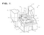
- Figure 1 is a first perspective view of a fluid storage vessel according to the present disclosure
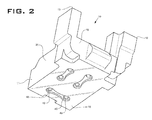
- Figure 2 is a second perspective view of the fluid storage vessel shown in Figure 1 ;
- Figure 3 a cross-sectional view through the fluid storage vessel of the previous figures, along the lines A-A shown in Figure 1 ;
- Figure 4 is a cross-sectional view through the fluid storage vessel shown in the previous figures, along the line B-B shown in Figure 1 ; the fluid storage vessel here being shown in a normal state; and
- Figure 5 is a cross-sectional view through the fluid storage vessel shown in the previous figures and along the line B-B of Figure 1 , the fluid storage vessel here being shown in a deformed state.
- the fluid storage vessel 10 may include a base portion 11 and first and second extension portions 12,13 upstanding from two corners of the base portion 11.
- the base portion 11 and the first and second extension portions 12,13 may together define an interior space 14 for carrying fluid.
- the shape of the fluid storage vessel 10 may be selected according to its intended purpose.
- the vessel 10 may comprise a fuel tank arranged for fluid communication with an engine (not shown) for installation on a vehicle (not shown).
- the fluid storage vessel 10 may be arranged for disposal within the chassis of the vehicle and may thus be shaped according to the space available within the chassis.
- the first and second extension portions 12,13 may be included to make use of the available space on the assembled vehicle.
- the first and second extension portions 12,13 may be furnished with a fluid fill port (not shown) and a breather system (not shown), which may be easily accessible on the assembled vehicle due to the height of the first and second extension portions.
- the fluid storage vessel 10 may be used to carry other fluids and may be configured to connect to other machines (not shown) and adapted to fit within differently shaped spaces within the chassis.
- the base portion 11 may be generally rectangular and may include a front wall 15, a rear wall 16, an upper wall 17, a lower wall 18, and first and second side walls 19,20.
- the first and second extension portions 12,13 may be located alongside the first and second side walls 19,20, respectively and adjacent the rear wall 16. It will be apparent to the skilled addressee that the number and location of the first and second extension portions 12,13 may vary according to the space available within the chassis or other machine constraints.
- the upper and lower walls 17,18 may be substantially planar and may have interior surfaces 17a,18a and exterior surfaces 17b,18b which may be arranged substantially parallel to one another.
- the walls of the fluid storage vessel are generally formed of a single layer and each may for the most part have a substantially uniform thickness.
- the upper wall 17 may be provided with a channel 22 arranged to extend between the first and second side walls 19,20.
- the channel 22 may have a front face 23 arranged at an angle to the upper and or lower walls 17,18 and may also have a rear face 24 arranged at an angle to the front face 23.
- the front and rear faces 23,24 may be arranged such that the channel 22 is substantially V-shaped.
- the fluid storage vessel 10 may also be furnished with a suction line 30 for drawing fluid from the interior space 14.
- the suction line 30 may comprise a rigid conduit arranged to extend through an opening (not shown) formed in a wall 17 of the fluid storage vessel 10. In the present embodiment, the opening is formed in the front face 23 of the channel 22.
- the fluid storage vessel 10 may also include a connector 31 to hold the suction line 30 in position and to provide a seal between the suction line 30 and the fluid storage vessel 10 to restrict leakage.
- the connector 31 may comprise an abutment portion 32 for engagement with the exterior surface 17b of the fluid storage vessel 10, a hole (not shown) through the abutment portion 32 and an annular wall 33 projecting from the abutment portion 32 so as to encircle the hole.
- the hole is sized and shaped to receive the suction line 30 in a secure and sealed manner so as to prevent relative movement between the suction line 30 and the upper wall 17 and to prevent the escape of fluid.
- Adhesive may be applied to aid with the securing and sealing of the suction line 30 within the hole.
- the annular wall 33 may be provided with an external thread (not shown) for engagement with an internal thread (not shown) formed in the opening. The inter-engagement of the threads draw the abutment portion onto the exterior surface of the upper wall and thus provide a good seal between the connector and the fluid storage vessel 10.
- the suction line 30 may have an internal end 35 disposed inside the fluid storage vessel 10 and may have an external end 36 disposed outside the fluid storage vessel, the internal end 35 defining a fluid inlet 35a and the external end defining a fluid outlet 36a.
- the internal end 35 may be spaced slightly above and may extend at an angle to the interior surface 18a of the lower wall 18.
- the fluid storage vessel 10 may also include one or more strengthening members, such as struts 40, extending between the upper and lower walls 17,18.
- the struts 40 are located inside the fluid storage vessel 10 and are arranged to resist deformation of the upper and lower walls 17,18 in the vicinity thereof. Their primary function is to resist inward deflection of the upper and lower walls 17,18 which might result from a vacuum in the fluid storage vessel, caused possibly by a plugged breather. However, the struts 40 may also serve to resist outward deflection and subsequent splitting caused by a pressure rise in the fluid storage vessel 10, which might also result from a plugged breather.
- the struts 40 are forward of the suction line 30 so as to define a reinforced region and a non-reinforced region. The quantity, size, shape and spatial relationship of the struts 40 may vary according to the size and shape of the fluid storage vessel 10 and its method of manufacture.
- the fluid storage vessel 10 may include multiple sets of struts 40 and each of those sets may have discreet means by which its struts 40 attach to the upper and lower walls 17,18.
- those discreet means may comprise upper and lower platforms 43,44 projecting into the interior space 14 from the interior faces 17a,18a of the upper and lower walls 17,18, the number of platforms 43,44 on each of the upper and lower walls 17,18 may correspond to the number of sets of struts.
- the fluid storage vessel 10 includes three sets of struts 40 so the upper wall 17 includes three platforms 43 and the lower wall 18 includes three lower platforms 44.
- the struts 40 in each group may be substantially parallel to each other and normal to the upper and lower walls 17,18 so the upper and lower platforms 43,44 for each group may therefore be arranged opposite one another.
- the fluid storage vessel 10 of the present embodiment may be molded or cast and may be provided with multiple recesses 45 in the exterior faces 17b,18b of the upper and lower walls 17,18. Each recess 45 in the exterior faces 17b,18b may result in a projection on the interior face 17a,18a so as to define the platform 43,44.
- the front set of struts 40a includes two struts spaced laterally apart on a front notional line (not shown) extending between the first and second side walls 19,20.
- the upper and lower walls 17,18 include upper and lower front platforms 43a,44a arranged to face one another and to extend partway between the first and second side walls 19,20.
- the first and second rear sets of struts 40b,40c may each include two struts which may be spaced laterally apart on rear notional lines (not shown) extending between the front and rear walls 15,16.
- the rear notional lines may be substantially parallel to one another such that the first set of struts 40b is proximal to the first side wall 19 and the second set of struts 40c is proximal to the second side wall 20. More specifically, the first and second rear sets of struts 40b,40c may be spaced the same distance from the first and second side walls 19,20, respectively.
- a lower portion of the internal end 35 of the suction line 30 may extend partway between the first and second rear sets of struts 40b,40c.
- the struts 40 may be substantially solid or tubular or a mixture of the two.
- the struts 40 are cylindrical and tubular, and each has opposed upper and lower ends attached to upper and lower platforms 43,44.
- Each strut 40 has a hollow interior which, in combination with upper and lower openings 47,48 formed in its respective upper and lower platforms 43,44, defines a through hole 49 extending through the fluid storage vessel 10.
- the fluid storage vessel 10 as described above is very likely produced from a moulding, or possibly a casting, process.
- the apparatus (not shown) for the chosen process would possibly include outer moulds to create the fluid storage vessel 10 and inner cores to create the interior spaces 14 and the through holes 49.
- the moulds would be sized and shaped according to the desired size and shape of the resulting fluid storage vessel, which would probably be determined by the space available in the machine in which it is to be mounted.
- fluid is drawn from the tank via the suction line 30 which may be associated with a lift pump (not shown) or the like.
- the breather will be operating effectively, which will allow air to pass into interior space 14 of the fluid storage vessel 10 as the fluid level drops and the pressure in said fluid storage vessel 10 is equalized.
- a vacuum will be created within the fluid storage vessel 10 due to the internal and external pressure difference.
- the fluid storage vessel 10 will eventually start to deform.
- the compressive strength of the struts 40 will resist deformation of the upper and lower walls 17,18 in the reinforcement area of the fluid storage vessel 10.
Landscapes
- Engineering & Computer Science (AREA)
- Mechanical Engineering (AREA)
- Chemical & Material Sciences (AREA)
- Life Sciences & Earth Sciences (AREA)
- Sustainable Development (AREA)
- Sustainable Energy (AREA)
- Combustion & Propulsion (AREA)
- Transportation (AREA)
- General Engineering & Computer Science (AREA)
- Mining & Mineral Resources (AREA)
- Civil Engineering (AREA)
- Structural Engineering (AREA)
- Filling Or Discharging Of Gas Storage Vessels (AREA)
- Cooling, Air Intake And Gas Exhaust, And Fuel Tank Arrangements In Propulsion Units (AREA)
Abstract
Description
- The present disclosure relates to a fluid storage vessel and in particular a fluid storage vessel having a suction line through which fluid may be drawn from the vessel.
- Fluid storage vessels are provided in many machines for storing fluid used during the operation of those machines. Such machines may include, for example, an engine, a pump, a vehicle, and so on. The fluid may take the form of a liquid or a gas and may be of a consumable nature such as fuel or a reusable nature such as lubricant, coolant or hydraulic fluid.
- Fluid storage vessels of this nature may be made of metals or plastics materials. Plastics materials are particularly favorable since they can be easily moulded to form a vessel with a more complex shape in order to make use of all available space within the structure in which they are to be mounted, such as a vehicle frame. Fluid storage vessels may include a suction line extending into the interior of the vessel and through which fluid may be drawn. The suction line may include a rigid conduit having a first end disposed within the interior of the vessel proximal to a lower portion and a second end disposed on the exterior of the vessel proximal to an upper portion. The suction line is commonly made of a rigid material to ensure the first end remains proximal to the lowermost portion (usually the base) so as to be submersed in the fluid regardless of the fluid level.
- Fluid storage vessels also include a filling port through which the fluid in the vessel may be replenished. The filling port may be opened and closed by a conventional cap.
- Breather systems are provided on most fluid storage vessels to ensure the pressure within the vessels remains at an acceptable level. The breather system provides a flow path for air to exit the vessel when fluid is being replenished and for air to enter the vessel when fluid is being drawn. In the absence of a fully working breather to facilitate the flow of air into the vessel while fluid is being drawn, a vacuum would be created thus inhibiting further fluid being drawn or leading to deformation of the vessel. The breather system may be provided in the wall of the fluid storage vessel or in association with the filling port, such as in the cap.
- The ability of the breather system to allow air to pass in and out of the vessel may reduce with age, particularly when used in dirty conditions as the debris in the ambient air may collect in its pores, which is known as plugging. The breather system should be cleaned or replaced when plugging occurs so as to restore the fluid storage vessel to its normal operating efficiency. However, sometimes plugging may go unnoticed for sometime and the size of the vacuum created inside the vessel may lead to deformation. Small vacuums may cause elastic deformation while large vacuums may lead to plastic deformation and thus irreparable damage to the vessel. However, even small amounts of deformation can damage the suction line as the inward deflection of the upper and lower portions of the vessel can bend the suction line and thus restrict the flow of fluid out of the vessel.
- It is an object of the present disclosure at least partially to address the shortcomings noted above in connection with existing fluid storage vessels.
- According to the present disclosure, there is provided a fluid storage vessel comprising: upper and lower walls at least partially defining an interior space for carrying fluid; at least one strengthening member extending between the upper and lower walls; and a suction line extending into the interior space and having a lower section defining an inlet configured to draw fluid, the lower section being arranged at an angle relative to a portion of the lower wall proximal to the lower section.
- By way of example only, one embodiment of the present disclosure will now be described in detail, with reference being made to the accompanying drawings, in which:
-
Figure 1 is a first perspective view of a fluid storage vessel according to the present disclosure; -
Figure 2 is a second perspective view of the fluid storage vessel shown inFigure 1 ; -
Figure 3 a cross-sectional view through the fluid storage vessel of the previous figures, along the lines A-A shown inFigure 1 ; -
Figure 4 is a cross-sectional view through the fluid storage vessel shown in the previous figures, along the line B-B shown inFigure 1 ; the fluid storage vessel here being shown in a normal state; and -
Figure 5 is a cross-sectional view through the fluid storage vessel shown in the previous figures and along the line B-B ofFigure 1 , the fluid storage vessel here being shown in a deformed state. - The following is a detailed description of an exemplary embodiment of the present disclosure. The exemplary embodiment described therein and illustrated in the drawings is intended to teach the principles of the present disclosure, enabling those of ordinary skill in the art to implement and use the present disclosure in many different environments and for many different applications. Therefore, the exemplary embodiment is not intended to be, and should not be considered as, a limiting description of the scope of patent protection. Rather, the scope of patent protection shall be defined by the appended claims.
- Referring initially to
Figures 1 and2 , there is shown a fluid storage vessel generally indicated 10. Thefluid storage vessel 10 may include abase portion 11 and first andsecond extension portions base portion 11. Thebase portion 11 and the first andsecond extension portions interior space 14 for carrying fluid. - The shape of the
fluid storage vessel 10 may be selected according to its intended purpose. For example, thevessel 10 may comprise a fuel tank arranged for fluid communication with an engine (not shown) for installation on a vehicle (not shown). Thefluid storage vessel 10 may be arranged for disposal within the chassis of the vehicle and may thus be shaped according to the space available within the chassis. The first andsecond extension portions second extension portions fluid storage vessel 10 may be used to carry other fluids and may be configured to connect to other machines (not shown) and adapted to fit within differently shaped spaces within the chassis. - The
base portion 11 may be generally rectangular and may include afront wall 15, arear wall 16, anupper wall 17, alower wall 18, and first andsecond side walls second extension portions second side walls rear wall 16. It will be apparent to the skilled addressee that the number and location of the first andsecond extension portions - The upper and
lower walls interior surfaces exterior surfaces upper wall 17 may be provided with achannel 22 arranged to extend between the first andsecond side walls channel 22 may have afront face 23 arranged at an angle to the upper and orlower walls rear face 24 arranged at an angle to thefront face 23. The front andrear faces channel 22 is substantially V-shaped. - The
fluid storage vessel 10 may also be furnished with asuction line 30 for drawing fluid from theinterior space 14. Thesuction line 30 may comprise a rigid conduit arranged to extend through an opening (not shown) formed in awall 17 of thefluid storage vessel 10. In the present embodiment, the opening is formed in thefront face 23 of thechannel 22. Thefluid storage vessel 10 may also include aconnector 31 to hold thesuction line 30 in position and to provide a seal between thesuction line 30 and thefluid storage vessel 10 to restrict leakage. Theconnector 31 may comprise anabutment portion 32 for engagement with theexterior surface 17b of thefluid storage vessel 10, a hole (not shown) through theabutment portion 32 and anannular wall 33 projecting from theabutment portion 32 so as to encircle the hole. The hole is sized and shaped to receive thesuction line 30 in a secure and sealed manner so as to prevent relative movement between thesuction line 30 and theupper wall 17 and to prevent the escape of fluid. Adhesive may be applied to aid with the securing and sealing of thesuction line 30 within the hole. Theannular wall 33 may be provided with an external thread (not shown) for engagement with an internal thread (not shown) formed in the opening. The inter-engagement of the threads draw the abutment portion onto the exterior surface of the upper wall and thus provide a good seal between the connector and thefluid storage vessel 10. - The
suction line 30 may have aninternal end 35 disposed inside thefluid storage vessel 10 and may have anexternal end 36 disposed outside the fluid storage vessel, theinternal end 35 defining afluid inlet 35a and the external end defining afluid outlet 36a. Theinternal end 35 may be spaced slightly above and may extend at an angle to theinterior surface 18a of thelower wall 18. - The
fluid storage vessel 10 may also include one or more strengthening members, such as struts 40, extending between the upper andlower walls fluid storage vessel 10 and are arranged to resist deformation of the upper andlower walls lower walls fluid storage vessel 10, which might also result from a plugged breather. In the present embodiment the struts 40 are forward of thesuction line 30 so as to define a reinforced region and a non-reinforced region. The quantity, size, shape and spatial relationship of the struts 40 may vary according to the size and shape of thefluid storage vessel 10 and its method of manufacture. - The
fluid storage vessel 10 may include multiple sets of struts 40 and each of those sets may have discreet means by which its struts 40 attach to the upper andlower walls interior space 14 from the interior faces 17a,18a of the upper andlower walls lower walls fluid storage vessel 10 includes three sets of struts 40 so theupper wall 17 includes three platforms 43 and thelower wall 18 includes three lower platforms 44. The struts 40 in each group may be substantially parallel to each other and normal to the upper andlower walls - The
fluid storage vessel 10 of the present embodiment may be molded or cast and may be provided with multiple recesses 45 in the exterior faces 17b,18b of the upper andlower walls interior face - In the present arrangement, there is provided one front set of
struts 40a and two rear sets ofstruts 40b,40c. The front set ofstruts 40a includes two struts spaced laterally apart on a front notional line (not shown) extending between the first andsecond side walls lower walls front platforms second side walls - The first and second rear sets of
struts 40b,40c may each include two struts which may be spaced laterally apart on rear notional lines (not shown) extending between the front andrear walls struts 40b is proximal to thefirst side wall 19 and the second set of struts 40c is proximal to thesecond side wall 20. More specifically, the first and second rear sets ofstruts 40b,40c may be spaced the same distance from the first andsecond side walls internal end 35 of thesuction line 30 may extend partway between the first and second rear sets ofstruts 40b,40c. - The struts 40 may be substantially solid or tubular or a mixture of the two. In the present embodiment the struts 40 are cylindrical and tubular, and each has opposed upper and lower ends attached to upper and lower platforms 43,44. Each strut 40 has a hollow interior which, in combination with upper and
lower openings hole 49 extending through thefluid storage vessel 10. - The
fluid storage vessel 10 as described above is very likely produced from a moulding, or possibly a casting, process. The apparatus (not shown) for the chosen process would possibly include outer moulds to create thefluid storage vessel 10 and inner cores to create theinterior spaces 14 and the through holes 49. The moulds would be sized and shaped according to the desired size and shape of the resulting fluid storage vessel, which would probably be determined by the space available in the machine in which it is to be mounted. - In use, fluid is drawn from the tank via the
suction line 30 which may be associated with a lift pump (not shown) or the like. Generally, the breather will be operating effectively, which will allow air to pass intointerior space 14 of thefluid storage vessel 10 as the fluid level drops and the pressure in saidfluid storage vessel 10 is equalized. However, in the event that the breather is plugged and no air is able to enter theinterior space 14, a vacuum will be created within thefluid storage vessel 10 due to the internal and external pressure difference. As the pressure difference increases due to the lift pump's ability to continue to draw fuel, thefluid storage vessel 10 will eventually start to deform. The compressive strength of the struts 40 will resist deformation of the upper andlower walls fluid storage vessel 10. However, deformation will likely occur in the non-reinforcement area as there is nothing or little to resist the inward deflection of the upper andlower walls lower walls channel 22.Figures 4 and5 show the vessel before and after deformation and from which it is clear that the upper andlower walls channel 22 is drawn inward and forward which causes the angle of thefront face 23 to reduce relative to theupper wall 17. As the angle of thefront face 23 changes, thesuction line 30 pivots approximately about theconnector 31 such that its lower portion moves forward and away from theinner face 18a of thelower wall 18.
Claims (16)
- A fluid storage vessel comprising:upper and lower walls at least partially defining an interior space for carrying fluid;at least one strengthening member extending between the upper and lower walls; anda suction line extending into the interior space and having a lower section defining an inlet configured to draw fluid, the lower section being arranged at an angle relative to a portion of the lower wall proximal to the lower section.
- A fluid storage vessel as claimed in claim 1, where the suction line extends through an opening in the upper wall.
- A fluid storage vessel as claimed in claim 1 or claim 2, wherein the lower section is generally rectilinear.
- A fluid storage vessel as claimed in any preceding claim, wherein the upper wall includes a mounting portion arranged at an angle to the lower wall and the suction line extends from the mounting portion.
- A fluid storage vessel as claimed in claim 4, wherein the suction line extends generally perpendicular to the mounting portion.
- A fluid storage vessel as claimed in claim 4 or claim 5, wherein a channel portion is formed in the upper wall and the mounting portion is defined by the channel portion.
- A fluid storage vessel as claimed in any preceding claim, wherein the suction line is a substantially rigid conduit through which fluid may be transmitted.
- A fluid storage vessel as claimed in any preceding claim, wherein the at least one strengthening member is integral to the upper and lower walls of the fluid storage vessel.
- A fluid storage vessel as claimed in claim 8, wherein the at least one strengthening member is generally tubular so as to define a hollow interior and the upper and lower walls each include at least one hole arranged coaxially with the hollow interior.
- A fluid storage vessel as claimed in any preceding claim, and further comprising front and rear opposed end walls extending between the upper and lower walls, the at least one strengthening member being located towards the front end wall and the suction line being located towards the rear end wall.
- A fluid storage vessel as claimed in any preceding claim, and further comprising first and second side walls and first and second strengthening members disposed proximal to the first and second side walls respectively, the lower portion of the suction line being disposed at least partway between those first and second strengthening members.
- A fluid storage vessel as claimed in claim 11, wherein:the first strengthening member comprises first upper and lower platforms projecting into the interior space from the upper and lower walls and a plurality of first struts extending between the first upper and lower platforms; andthe second strengthening member comprises second upper and lower platforms projecting into the interior space from the upper and lower walls and a plurality of second struts extending between the second upper and lower platforms.
- A fluid storage vessel as claimed in claim 12, wherein the struts in each of the first and second strengthening members are arranged substantially in a line so as to form two substantially parallel rows of first and second struts.
- A fluid storage vessel as claimed in claims 10 and 11, wherein a third strengthening member is disposed between the front end wall and the first and second strengthening members.
- A fluid storage vessel as claimed in claims 13 and 14, wherein the third strengthening member comprises a plurality of struts arranged substantially in a row running normal to the rows of first and second struts.
- A method of using a fluid storage vessel comprising a base at least partially defining an interior space, a suction line extending into the interior space, and a breather for permitting gas to enter and leave the interior space, the method comprising the steps of:rendering the breather at least partially ineffective;drawing fluid from the interior space so as to cause a partial vacuum within the fluid storage vessel;causing deformation of the fluid storage vessel; andcausing the suction line to deflect upwardly away from the base of the fluid storage vessel.
Applications Claiming Priority (1)
| Application Number | Priority Date | Filing Date | Title |
|---|---|---|---|
| GB1217195.5A GB2506366B (en) | 2012-09-26 | 2012-09-26 | Fluid storage vessel |
Publications (2)
| Publication Number | Publication Date |
|---|---|
| EP2712753A1 true EP2712753A1 (en) | 2014-04-02 |
| EP2712753B1 EP2712753B1 (en) | 2017-03-22 |
Family
ID=47190655
Family Applications (1)
| Application Number | Title | Priority Date | Filing Date |
|---|---|---|---|
| EP13182662.0A Not-in-force EP2712753B1 (en) | 2012-09-26 | 2013-09-02 | Fluid storage vessel |
Country Status (2)
| Country | Link |
|---|---|
| EP (1) | EP2712753B1 (en) |
| GB (1) | GB2506366B (en) |
Citations (4)
| Publication number | Priority date | Publication date | Assignee | Title |
|---|---|---|---|---|
| US4453564A (en) * | 1981-04-16 | 1984-06-12 | Fiat Auto S.P.A. | Fuel tank for motor vehicles |
| DE4413846A1 (en) * | 1993-04-30 | 1994-11-03 | Volkswagen Ag | Retainer |
| US20080302805A1 (en) * | 2007-06-05 | 2008-12-11 | Kubota Corporation | Fuel Tank for Work Vehicle |
| JP2010285064A (en) * | 2009-06-11 | 2010-12-24 | Honda Motor Co Ltd | Resin fuel tank |
Family Cites Families (1)
| Publication number | Priority date | Publication date | Assignee | Title |
|---|---|---|---|---|
| KR100308140B1 (en) * | 1998-05-26 | 2001-12-12 | 성재갑 | Method for manufacturing plastic fuel tank of vehicle with improving impact resistance by preventing notch of reinforcing connection part |
-
2012
- 2012-09-26 GB GB1217195.5A patent/GB2506366B/en not_active Expired - Fee Related
-
2013
- 2013-09-02 EP EP13182662.0A patent/EP2712753B1/en not_active Not-in-force
Patent Citations (4)
| Publication number | Priority date | Publication date | Assignee | Title |
|---|---|---|---|---|
| US4453564A (en) * | 1981-04-16 | 1984-06-12 | Fiat Auto S.P.A. | Fuel tank for motor vehicles |
| DE4413846A1 (en) * | 1993-04-30 | 1994-11-03 | Volkswagen Ag | Retainer |
| US20080302805A1 (en) * | 2007-06-05 | 2008-12-11 | Kubota Corporation | Fuel Tank for Work Vehicle |
| JP2010285064A (en) * | 2009-06-11 | 2010-12-24 | Honda Motor Co Ltd | Resin fuel tank |
Also Published As
| Publication number | Publication date |
|---|---|
| GB2506366A (en) | 2014-04-02 |
| GB2506366B (en) | 2015-01-28 |
| GB201217195D0 (en) | 2012-11-07 |
| EP2712753B1 (en) | 2017-03-22 |
Similar Documents
| Publication | Publication Date | Title |
|---|---|---|
| US6508271B2 (en) | Rotomolded hydraulic reservoir with integral extended length return line | |
| DE102009042275A1 (en) | Siphon tube for a multi-chamber fluid reservoir | |
| KR102053628B1 (en) | Ink tank | |
| US11560049B2 (en) | Fill limit venting valve with high shut-off height | |
| EP3201479B1 (en) | A hydraulic fluid tank arrangement | |
| EP2748454B1 (en) | Liquid fuel trap device | |
| CN106488855B (en) | Storage containers for aqueous urea solutions in motor vehicles | |
| US20170355196A1 (en) | Ink replenish adjunctive device and ink replenish device | |
| US10220701B2 (en) | Utility vehicle tank | |
| EP2712753A1 (en) | Fluid storage vessel | |
| EP3476642B1 (en) | Fuel tank | |
| CN108602428A (en) | Saddle type container with spilling barrier | |
| KR101159234B1 (en) | Drain oil tank for ship | |
| US7726791B2 (en) | Conduit construction using films | |
| CN110513338A (en) | Hydraulic system semi-closed oil tank | |
| JP5074909B2 (en) | Fuel tank structure | |
| CN210235823U (en) | a liquid storage tank | |
| JP5490427B2 (en) | Fuel tank system | |
| JP4986920B2 (en) | Piping blocker for hydraulic oil tank | |
| EP2685108B1 (en) | Oil tank | |
| CN204126988U (en) | Self-unloading vehicle hydraulic system Fuel Tanking Unit | |
| CN222408228U (en) | Liquid storage tank | |
| JP5775713B2 (en) | Oil pump and oil pump lid | |
| JPH0534324Y2 (en) | ||
| CN115867720A (en) | Flange covers, delivery module assemblies, operating medium containers and modular operating medium container systems |
Legal Events
| Date | Code | Title | Description |
|---|---|---|---|
| PUAI | Public reference made under article 153(3) epc to a published international application that has entered the european phase |
Free format text: ORIGINAL CODE: 0009012 |
|
| AK | Designated contracting states |
Kind code of ref document: A1 Designated state(s): AL AT BE BG CH CY CZ DE DK EE ES FI FR GB GR HR HU IE IS IT LI LT LU LV MC MK MT NL NO PL PT RO RS SE SI SK SM TR |
|
| AX | Request for extension of the european patent |
Extension state: BA ME |
|
| 17P | Request for examination filed |
Effective date: 20141002 |
|
| RBV | Designated contracting states (corrected) |
Designated state(s): AL AT BE BG CH CY CZ DE DK EE ES FI FR GB GR HR HU IE IS IT LI LT LU LV MC MK MT NL NO PL PT RO RS SE SI SK SM TR |
|
| 17Q | First examination report despatched |
Effective date: 20160308 |
|
| GRAP | Despatch of communication of intention to grant a patent |
Free format text: ORIGINAL CODE: EPIDOSNIGR1 |
|
| INTG | Intention to grant announced |
Effective date: 20161021 |
|
| GRAS | Grant fee paid |
Free format text: ORIGINAL CODE: EPIDOSNIGR3 |
|
| GRAA | (expected) grant |
Free format text: ORIGINAL CODE: 0009210 |
|
| AK | Designated contracting states |
Kind code of ref document: B1 Designated state(s): AL AT BE BG CH CY CZ DE DK EE ES FI FR GB GR HR HU IE IS IT LI LT LU LV MC MK MT NL NO PL PT RO RS SE SI SK SM TR |
|
| REG | Reference to a national code |
Ref country code: GB Ref legal event code: FG4D |
|
| REG | Reference to a national code |
Ref country code: CH Ref legal event code: EP |
|
| REG | Reference to a national code |
Ref country code: AT Ref legal event code: REF Ref document number: 877361 Country of ref document: AT Kind code of ref document: T Effective date: 20170415 |
|
| REG | Reference to a national code |
Ref country code: IE Ref legal event code: FG4D |
|
| REG | Reference to a national code |
Ref country code: DE Ref legal event code: R096 Ref document number: 602013018804 Country of ref document: DE |
|
| REG | Reference to a national code |
Ref country code: NL Ref legal event code: MP Effective date: 20170322 |
|
| PG25 | Lapsed in a contracting state [announced via postgrant information from national office to epo] |
Ref country code: LT Free format text: LAPSE BECAUSE OF FAILURE TO SUBMIT A TRANSLATION OF THE DESCRIPTION OR TO PAY THE FEE WITHIN THE PRESCRIBED TIME-LIMIT Effective date: 20170322 Ref country code: GR Free format text: LAPSE BECAUSE OF FAILURE TO SUBMIT A TRANSLATION OF THE DESCRIPTION OR TO PAY THE FEE WITHIN THE PRESCRIBED TIME-LIMIT Effective date: 20170623 Ref country code: FI Free format text: LAPSE BECAUSE OF FAILURE TO SUBMIT A TRANSLATION OF THE DESCRIPTION OR TO PAY THE FEE WITHIN THE PRESCRIBED TIME-LIMIT Effective date: 20170322 Ref country code: HR Free format text: LAPSE BECAUSE OF FAILURE TO SUBMIT A TRANSLATION OF THE DESCRIPTION OR TO PAY THE FEE WITHIN THE PRESCRIBED TIME-LIMIT Effective date: 20170322 Ref country code: NO Free format text: LAPSE BECAUSE OF FAILURE TO SUBMIT A TRANSLATION OF THE DESCRIPTION OR TO PAY THE FEE WITHIN THE PRESCRIBED TIME-LIMIT Effective date: 20170622 |
|
| REG | Reference to a national code |
Ref country code: LT Ref legal event code: MG4D |
|
| REG | Reference to a national code |
Ref country code: AT Ref legal event code: MK05 Ref document number: 877361 Country of ref document: AT Kind code of ref document: T Effective date: 20170322 |
|
| PG25 | Lapsed in a contracting state [announced via postgrant information from national office to epo] |
Ref country code: LV Free format text: LAPSE BECAUSE OF FAILURE TO SUBMIT A TRANSLATION OF THE DESCRIPTION OR TO PAY THE FEE WITHIN THE PRESCRIBED TIME-LIMIT Effective date: 20170322 Ref country code: SE Free format text: LAPSE BECAUSE OF FAILURE TO SUBMIT A TRANSLATION OF THE DESCRIPTION OR TO PAY THE FEE WITHIN THE PRESCRIBED TIME-LIMIT Effective date: 20170322 Ref country code: BG Free format text: LAPSE BECAUSE OF FAILURE TO SUBMIT A TRANSLATION OF THE DESCRIPTION OR TO PAY THE FEE WITHIN THE PRESCRIBED TIME-LIMIT Effective date: 20170622 Ref country code: RS Free format text: LAPSE BECAUSE OF FAILURE TO SUBMIT A TRANSLATION OF THE DESCRIPTION OR TO PAY THE FEE WITHIN THE PRESCRIBED TIME-LIMIT Effective date: 20170322 |
|
| PG25 | Lapsed in a contracting state [announced via postgrant information from national office to epo] |
Ref country code: NL Free format text: LAPSE BECAUSE OF FAILURE TO SUBMIT A TRANSLATION OF THE DESCRIPTION OR TO PAY THE FEE WITHIN THE PRESCRIBED TIME-LIMIT Effective date: 20170322 |
|
| PG25 | Lapsed in a contracting state [announced via postgrant information from national office to epo] |
Ref country code: RO Free format text: LAPSE BECAUSE OF FAILURE TO SUBMIT A TRANSLATION OF THE DESCRIPTION OR TO PAY THE FEE WITHIN THE PRESCRIBED TIME-LIMIT Effective date: 20170322 Ref country code: IT Free format text: LAPSE BECAUSE OF FAILURE TO SUBMIT A TRANSLATION OF THE DESCRIPTION OR TO PAY THE FEE WITHIN THE PRESCRIBED TIME-LIMIT Effective date: 20170322 Ref country code: ES Free format text: LAPSE BECAUSE OF FAILURE TO SUBMIT A TRANSLATION OF THE DESCRIPTION OR TO PAY THE FEE WITHIN THE PRESCRIBED TIME-LIMIT Effective date: 20170322 Ref country code: AT Free format text: LAPSE BECAUSE OF FAILURE TO SUBMIT A TRANSLATION OF THE DESCRIPTION OR TO PAY THE FEE WITHIN THE PRESCRIBED TIME-LIMIT Effective date: 20170322 Ref country code: CZ Free format text: LAPSE BECAUSE OF FAILURE TO SUBMIT A TRANSLATION OF THE DESCRIPTION OR TO PAY THE FEE WITHIN THE PRESCRIBED TIME-LIMIT Effective date: 20170322 Ref country code: SK Free format text: LAPSE BECAUSE OF FAILURE TO SUBMIT A TRANSLATION OF THE DESCRIPTION OR TO PAY THE FEE WITHIN THE PRESCRIBED TIME-LIMIT Effective date: 20170322 Ref country code: EE Free format text: LAPSE BECAUSE OF FAILURE TO SUBMIT A TRANSLATION OF THE DESCRIPTION OR TO PAY THE FEE WITHIN THE PRESCRIBED TIME-LIMIT Effective date: 20170322 |
|
| PG25 | Lapsed in a contracting state [announced via postgrant information from national office to epo] |
Ref country code: IS Free format text: LAPSE BECAUSE OF FAILURE TO SUBMIT A TRANSLATION OF THE DESCRIPTION OR TO PAY THE FEE WITHIN THE PRESCRIBED TIME-LIMIT Effective date: 20170722 Ref country code: SM Free format text: LAPSE BECAUSE OF FAILURE TO SUBMIT A TRANSLATION OF THE DESCRIPTION OR TO PAY THE FEE WITHIN THE PRESCRIBED TIME-LIMIT Effective date: 20170322 Ref country code: PL Free format text: LAPSE BECAUSE OF FAILURE TO SUBMIT A TRANSLATION OF THE DESCRIPTION OR TO PAY THE FEE WITHIN THE PRESCRIBED TIME-LIMIT Effective date: 20170322 Ref country code: PT Free format text: LAPSE BECAUSE OF FAILURE TO SUBMIT A TRANSLATION OF THE DESCRIPTION OR TO PAY THE FEE WITHIN THE PRESCRIBED TIME-LIMIT Effective date: 20170724 |
|
| REG | Reference to a national code |
Ref country code: DE Ref legal event code: R097 Ref document number: 602013018804 Country of ref document: DE |
|
| PLBE | No opposition filed within time limit |
Free format text: ORIGINAL CODE: 0009261 |
|
| STAA | Information on the status of an ep patent application or granted ep patent |
Free format text: STATUS: NO OPPOSITION FILED WITHIN TIME LIMIT |
|
| PG25 | Lapsed in a contracting state [announced via postgrant information from national office to epo] |
Ref country code: DK Free format text: LAPSE BECAUSE OF FAILURE TO SUBMIT A TRANSLATION OF THE DESCRIPTION OR TO PAY THE FEE WITHIN THE PRESCRIBED TIME-LIMIT Effective date: 20170322 |
|
| 26N | No opposition filed |
Effective date: 20180102 |
|
| PG25 | Lapsed in a contracting state [announced via postgrant information from national office to epo] |
Ref country code: SI Free format text: LAPSE BECAUSE OF FAILURE TO SUBMIT A TRANSLATION OF THE DESCRIPTION OR TO PAY THE FEE WITHIN THE PRESCRIBED TIME-LIMIT Effective date: 20170322 |
|
| REG | Reference to a national code |
Ref country code: CH Ref legal event code: PL |
|
| GBPC | Gb: european patent ceased through non-payment of renewal fee |
Effective date: 20170902 |
|
| PG25 | Lapsed in a contracting state [announced via postgrant information from national office to epo] |
Ref country code: MC Free format text: LAPSE BECAUSE OF FAILURE TO SUBMIT A TRANSLATION OF THE DESCRIPTION OR TO PAY THE FEE WITHIN THE PRESCRIBED TIME-LIMIT Effective date: 20170322 |
|
| REG | Reference to a national code |
Ref country code: IE Ref legal event code: MM4A |
|
| REG | Reference to a national code |
Ref country code: BE Ref legal event code: MM Effective date: 20170930 |
|
| PG25 | Lapsed in a contracting state [announced via postgrant information from national office to epo] |
Ref country code: LU Free format text: LAPSE BECAUSE OF NON-PAYMENT OF DUE FEES Effective date: 20170902 |
|
| REG | Reference to a national code |
Ref country code: FR Ref legal event code: ST Effective date: 20180531 |
|
| PG25 | Lapsed in a contracting state [announced via postgrant information from national office to epo] |
Ref country code: GB Free format text: LAPSE BECAUSE OF NON-PAYMENT OF DUE FEES Effective date: 20170902 Ref country code: CH Free format text: LAPSE BECAUSE OF NON-PAYMENT OF DUE FEES Effective date: 20170930 Ref country code: LI Free format text: LAPSE BECAUSE OF NON-PAYMENT OF DUE FEES Effective date: 20170930 Ref country code: IE Free format text: LAPSE BECAUSE OF NON-PAYMENT OF DUE FEES Effective date: 20170902 |
|
| PG25 | Lapsed in a contracting state [announced via postgrant information from national office to epo] |
Ref country code: FR Free format text: LAPSE BECAUSE OF NON-PAYMENT OF DUE FEES Effective date: 20171002 Ref country code: BE Free format text: LAPSE BECAUSE OF NON-PAYMENT OF DUE FEES Effective date: 20170930 |
|
| PG25 | Lapsed in a contracting state [announced via postgrant information from national office to epo] |
Ref country code: MT Free format text: LAPSE BECAUSE OF NON-PAYMENT OF DUE FEES Effective date: 20170902 |
|
| PG25 | Lapsed in a contracting state [announced via postgrant information from national office to epo] |
Ref country code: HU Free format text: LAPSE BECAUSE OF FAILURE TO SUBMIT A TRANSLATION OF THE DESCRIPTION OR TO PAY THE FEE WITHIN THE PRESCRIBED TIME-LIMIT; INVALID AB INITIO Effective date: 20130902 |
|
| PG25 | Lapsed in a contracting state [announced via postgrant information from national office to epo] |
Ref country code: CY Free format text: LAPSE BECAUSE OF NON-PAYMENT OF DUE FEES Effective date: 20170322 |
|
| PGFP | Annual fee paid to national office [announced via postgrant information from national office to epo] |
Ref country code: DE Payment date: 20190813 Year of fee payment: 7 |
|
| PG25 | Lapsed in a contracting state [announced via postgrant information from national office to epo] |
Ref country code: MK Free format text: LAPSE BECAUSE OF FAILURE TO SUBMIT A TRANSLATION OF THE DESCRIPTION OR TO PAY THE FEE WITHIN THE PRESCRIBED TIME-LIMIT Effective date: 20170322 |
|
| PG25 | Lapsed in a contracting state [announced via postgrant information from national office to epo] |
Ref country code: TR Free format text: LAPSE BECAUSE OF FAILURE TO SUBMIT A TRANSLATION OF THE DESCRIPTION OR TO PAY THE FEE WITHIN THE PRESCRIBED TIME-LIMIT Effective date: 20170322 |
|
| PG25 | Lapsed in a contracting state [announced via postgrant information from national office to epo] |
Ref country code: AL Free format text: LAPSE BECAUSE OF FAILURE TO SUBMIT A TRANSLATION OF THE DESCRIPTION OR TO PAY THE FEE WITHIN THE PRESCRIBED TIME-LIMIT Effective date: 20170322 |
|
| REG | Reference to a national code |
Ref country code: DE Ref legal event code: R119 Ref document number: 602013018804 Country of ref document: DE |
|
| PG25 | Lapsed in a contracting state [announced via postgrant information from national office to epo] |
Ref country code: DE Free format text: LAPSE BECAUSE OF NON-PAYMENT OF DUE FEES Effective date: 20210401 |