EP2712751A1 - Working vehicle - Google Patents
Working vehicle Download PDFInfo
- Publication number
- EP2712751A1 EP2712751A1 EP12805504.3A EP12805504A EP2712751A1 EP 2712751 A1 EP2712751 A1 EP 2712751A1 EP 12805504 A EP12805504 A EP 12805504A EP 2712751 A1 EP2712751 A1 EP 2712751A1
- Authority
- EP
- European Patent Office
- Prior art keywords
- flange
- hose
- flanges
- cooling device
- engine
- Prior art date
- Legal status (The legal status is an assumption and is not a legal conclusion. Google has not performed a legal analysis and makes no representation as to the accuracy of the status listed.)
- Granted
Links
- 238000001816 cooling Methods 0.000 claims abstract description 45
- 238000005192 partition Methods 0.000 claims description 35
- XLYOFNOQVPJJNP-UHFFFAOYSA-N water Substances O XLYOFNOQVPJJNP-UHFFFAOYSA-N 0.000 abstract description 19
- 239000010720 hydraulic oil Substances 0.000 description 6
- 239000003921 oil Substances 0.000 description 4
- 238000009825 accumulation Methods 0.000 description 2
- 239000002826 coolant Substances 0.000 description 2
- 230000008878 coupling Effects 0.000 description 2
- 238000010168 coupling process Methods 0.000 description 2
- 238000005859 coupling reaction Methods 0.000 description 2
- 230000008602 contraction Effects 0.000 description 1
- 230000000694 effects Effects 0.000 description 1
- 230000004048 modification Effects 0.000 description 1
- 238000012986 modification Methods 0.000 description 1
- 239000011347 resin Substances 0.000 description 1
- 229920005989 resin Polymers 0.000 description 1
Images


Classifications
-
- F—MECHANICAL ENGINEERING; LIGHTING; HEATING; WEAPONS; BLASTING
- F16—ENGINEERING ELEMENTS AND UNITS; GENERAL MEASURES FOR PRODUCING AND MAINTAINING EFFECTIVE FUNCTIONING OF MACHINES OR INSTALLATIONS; THERMAL INSULATION IN GENERAL
- F16L—PIPES; JOINTS OR FITTINGS FOR PIPES; SUPPORTS FOR PIPES, CABLES OR PROTECTIVE TUBING; MEANS FOR THERMAL INSULATION IN GENERAL
- F16L3/00—Supports for pipes, cables or protective tubing, e.g. hangers, holders, clamps, cleats, clips, brackets
- F16L3/22—Supports for pipes, cables or protective tubing, e.g. hangers, holders, clamps, cleats, clips, brackets specially adapted for supporting a number of parallel pipes at intervals
- F16L3/23—Supports for pipes, cables or protective tubing, e.g. hangers, holders, clamps, cleats, clips, brackets specially adapted for supporting a number of parallel pipes at intervals for a bundle of pipes or a plurality of pipes placed side by side in contact with each other
-
- B—PERFORMING OPERATIONS; TRANSPORTING
- B60—VEHICLES IN GENERAL
- B60K—ARRANGEMENT OR MOUNTING OF PROPULSION UNITS OR OF TRANSMISSIONS IN VEHICLES; ARRANGEMENT OR MOUNTING OF PLURAL DIVERSE PRIME-MOVERS IN VEHICLES; AUXILIARY DRIVES FOR VEHICLES; INSTRUMENTATION OR DASHBOARDS FOR VEHICLES; ARRANGEMENTS IN CONNECTION WITH COOLING, AIR INTAKE, GAS EXHAUST OR FUEL SUPPLY OF PROPULSION UNITS IN VEHICLES
- B60K11/00—Arrangement in connection with cooling of propulsion units
- B60K11/02—Arrangement in connection with cooling of propulsion units with liquid cooling
- B60K11/04—Arrangement or mounting of radiators, radiator shutters, or radiator blinds
-
- E—FIXED CONSTRUCTIONS
- E02—HYDRAULIC ENGINEERING; FOUNDATIONS; SOIL SHIFTING
- E02F—DREDGING; SOIL-SHIFTING
- E02F9/00—Component parts of dredgers or soil-shifting machines, not restricted to one of the kinds covered by groups E02F3/00 - E02F7/00
- E02F9/08—Superstructures; Supports for superstructures
- E02F9/0858—Arrangement of component parts installed on superstructures not otherwise provided for, e.g. electric components, fenders, air-conditioning units
- E02F9/0866—Engine compartment, e.g. heat exchangers, exhaust filters, cooling devices, silencers, mufflers, position of hydraulic pumps in the engine compartment
-
- F—MECHANICAL ENGINEERING; LIGHTING; HEATING; WEAPONS; BLASTING
- F01—MACHINES OR ENGINES IN GENERAL; ENGINE PLANTS IN GENERAL; STEAM ENGINES
- F01P—COOLING OF MACHINES OR ENGINES IN GENERAL; COOLING OF INTERNAL-COMBUSTION ENGINES
- F01P11/00—Component parts, details, or accessories not provided for in, or of interest apart from, groups F01P1/00 - F01P9/00
- F01P11/04—Arrangements of liquid pipes or hoses
-
- B—PERFORMING OPERATIONS; TRANSPORTING
- B60—VEHICLES IN GENERAL
- B60Y—INDEXING SCHEME RELATING TO ASPECTS CROSS-CUTTING VEHICLE TECHNOLOGY
- B60Y2200/00—Type of vehicle
- B60Y2200/40—Special vehicles
- B60Y2200/41—Construction vehicles, e.g. graders, excavators
-
- B—PERFORMING OPERATIONS; TRANSPORTING
- B60—VEHICLES IN GENERAL
- B60Y—INDEXING SCHEME RELATING TO ASPECTS CROSS-CUTTING VEHICLE TECHNOLOGY
- B60Y2200/00—Type of vehicle
- B60Y2200/40—Special vehicles
- B60Y2200/41—Construction vehicles, e.g. graders, excavators
- B60Y2200/415—Wheel loaders
-
- Y—GENERAL TAGGING OF NEW TECHNOLOGICAL DEVELOPMENTS; GENERAL TAGGING OF CROSS-SECTIONAL TECHNOLOGIES SPANNING OVER SEVERAL SECTIONS OF THE IPC; TECHNICAL SUBJECTS COVERED BY FORMER USPC CROSS-REFERENCE ART COLLECTIONS [XRACs] AND DIGESTS
- Y10—TECHNICAL SUBJECTS COVERED BY FORMER USPC
- Y10T—TECHNICAL SUBJECTS COVERED BY FORMER US CLASSIFICATION
- Y10T137/00—Fluid handling
- Y10T137/6851—With casing, support, protector or static constructional installations
- Y10T137/6855—Vehicle
- Y10T137/6881—Automotive
Definitions
- the present invention relates to work vehicles, particularly a work vehicle including a partition arranged between an engine and a cooling device.
- Some work vehicles have an engine and a cooling device connected by a plurality of hoses.
- Japanese Patent Laying-Open No. 2003-182380 discloses a configuration in which a CAC (Charged Air Cooling) hose and a radiator hose are connected to the engine.
- CAC Charge Air Cooling
- an object of the present invention is to provide a work vehicle that can prevent rain water intruding inside from entering the engine side along a hose.
- a work vehicle of the present invention includes an engine, a cooling device, first and second hoses, first and second flanges, and a third flange.
- the first and second hoses are arranged between the engine and the cooling device for connection therebetween.
- the first and second flanges are formed at an outer circumferential face of the first hose to protrude outward of the first hose, and arranged spaced apart from each other.
- the third flange is formed at an outer circumferential face of the second hose to protrude outward of the second hose.
- the third flange is arranged to overlap with the first and second flanges by extending in a region sandwiched between the first flange and second flange.
- the third flange is arranged to overlap with the first and second flanges by extending in a region sandwiched between the first flange and the second flange. Therefore, the first to third flanges can prevent the rain water intruding inside from entering the engine side along the first and second hoses. Further, the provision of the first and second flanges at the first hose and the provision of the third flange at the second hose allows the first hose and the second hose to be connected to the engine individually. Accordingly, connection of the first hose and second hose to the engine can be facilitated.
- a partition having a first through hole is arranged between the engine and the cooling device.
- the first hose and the second hose pass through the first through hole in the partition. Therefore, the engine and cooling device can be connected at the shortest distance without the first and second hoses having to avoid the partition.
- each of the first to third flanges tilts downwards from the partition side towards the cooling device side. Any rain water adhering to the first to third flanges will flow towards the cooling device. Accordingly, the rain water adhering to the first to third flanges can be prevented from running to the engine side.
- the partition further includes a bracket at the cooling device side.
- the bracket includes a second through hole at the upper portion. Therefore, the first to third flanges can be arranged facing upwards.
- the first to third flanges are provided such that a projection shape of the first to third flanges from a mutually overlapping direction covers the second through hole entirely. Accordingly, the intrusion of the rain water passing through the second through hole from between the rims of the first to third flanges and the second through hole to enter the engine can be prevented.
- each of the first to third flanges has a circular outer shape.
- each of the first and second flanges overlaps with the third flange by a length greater than or equal to half a width of each relevant flange. Therefore, the overlapping area between the first flange and the third flange and the overlapping area between the second flange and the third flange can be ensured sufficiently. Thus, intrusion of rain water from between the first flange and the third flange and from between the second flange and the third flange into the engine side can be prevented reliably.
- the first flange and the second flange are arranged spaced apart from each other in the longitudinal direction of the first hose.
- the third flange arranged between the first and second flanges is spaced apart from the first flange in the longitudinal direction of the second hose, and spaced apart from the second flange in the longitudinal direction of the second hose.
- the first and second flanges are spaced apart from the second hose in a radial direction.
- the third flange is spaced apart from the first hose in a radial direction. Therefore, accumulation of rain water at the first to third flanges can be prevented.
- the work vehicle set forth above further includes a top panel arranged above the engine, the cooling device, and the partition.
- the top panel has a vent provided above the first and second hoses at the cooling device side relative to the partition. Accordingly, the first to third flanges prevent the rain water running in from the vent located above the first and second hoses from entering the engine side along the first and second hoses.
- each of the first to third flanges are formed integrally as each of first to third protruding members. Accordingly, the assembly is facilitated.
- a work vehicle that can prevent rain water intruding inside from entering the engine side along a hose.
- a wheel loader 1 of the present embodiment mainly includes a rear body 2, a front body 3, and work machinery 4.
- Each of the sides of front body 3 has a front wheel 5a attached.
- Each of the sides of rear body 2 has a rear wheel 5b attached.
- Rear body 2 and front body 3 are attached horizontally swingable by a center pin (not shown) to constitute an articulate structure. Specifically, rear body 2 and front body 3 are coupled by left and right steering cylinders (not shown) constituting a pair. The left and right steering cylinders are configured to elongate and contract such that rear body 2 and front body 3 sway left and right about the center pin for steering. Rear body 2 and front body 3 constitute the body part of wheel loader 1.
- Work machinery 4 is attached in front of front body 3.
- Work machinery 4 includes a boom 4a attached to front body 3 with its proximal end swingable, and a bucket 4b attached to the leading end of boom 4a in a swingable manner.
- Front body 3 is attached to boom 4a by a pair of boom cylinders 4c, 4c, and configured such that boom 4a sways by boom cylinders 4c, 4c elongating and contracting.
- Work machinery 4 includes a bell crank 4d supported swingably by boom 4a at substantially the central region, a bucket cylinder 4e coupling the proximal end of bell crank 4d with front body 3, and a link 4f coupling the leading end of bell crank 4d with bucket 4b.
- the elongation and contraction of bucket cylinder 4e causes bucket 4b to sway.
- An engine room 6a is arranged at the back of rear body 2.
- a hydraulic oil tank 7 is arranged in front of engine room 6a.
- a cab 8 where the operator enters to operate wheel loader 1 is located in front of hydraulic oil tank 7. The front and back as well as the left and right of wheel loader 1 are based on the operator sitting in cab 8 as the reference.
- a top panel 2a is arranged at the top face of rear body 2. Top panel 2a is located above engine room 6a in the state where wheel loader 1 is situated on a horizontal ground G.
- Cooling device 12 includes a CAC device 12a, a radiator (engine coolant cooling device) 12b, and an oil cooler (hydraulic oil cooling device) 12c.
- CAC device 12a, radiator 12b and oil cooler 12c are arranged in line at the back of engine room 6a.
- Engine room 6a is divided by a partition 13.
- Partition 13 is arranged between engine 11 and cooling device 12.
- Partition 13 includes a first through hole 13a.
- CAC hose (first hose) 14 and a radiator hose (second hose) 15 pass through first through hole 13a to connect engine 11 with cooling device 12.
- CAC hose 14 passes through first through hole 13a to connect engine 11 with CAC device 12a.
- Radiator hose 15 passes through first through hole 13a to connect engine 11 with radiator 12b.
- a hydraulic oil hose not shown is connected to oil cooler 12c.
- Top panel 2a is arranged above engine 11, cooling device 12 and partition 13.
- Top panel 2a includes a vent H provided above CAC hose 14 and radiator hose 15 at the side of cooling device 12 relative to partition 13.
- a plurality of vents H are formed.
- first protruding member 16 including a flange and a second protruding member 17 including a flange at CAC hose 14.
- a third protruding member 18 having a flange is attached at radiator hose 15.
- a plurality of vents H are arranged above first to third protruding members 16-18.
- an exhaust system filter (DPF: diesel particulate filter) 21 and an intake system filter 22 are arranged. Each of exhaust system filter 21 and intake system filter 22 is connected to engine 11. Exhaust system filter 21 is connected to an exhaust pipe 23 arranged above top panel 2a. Intake system filter 22 is connected to an air cleaner 24 arranged above top panel 2a. Furthermore, a cooling fan 19 is arranged behind cooling device 12.
- DPF diesel particulate filter
- first to third protruding members 16-18 will be described in detail.
- first protruding member 16 and second protruding member 17 will be described. Since first and second protruding members 16 and 17 have a similar configuration, the configuration of first protruding member 16 will be described representative thereof. The configuration of second protruding member 17 will not be described repeatedly, unless noted otherwise.
- First protruding member 15 includes a flat section 161, a taper section 162, and a cylindrical section 163.
- Flat section 161 is arranged at the outer circumferential end of first protruding member 16.
- Flat section 161 has a disk shape.
- Taper section 162 is located between flat section 161 and cylindrical section 163.
- Taper section 162 is inclined such that the diameter becomes smaller towards cylindrical section 163.
- Cylindrical section 163 protrudes in a direction where the diameter of taper section 162 becomes smaller than flat section 161.
- Cylindrical section 163 takes a cylindrical shape.
- Flat section 161 and the portion of taper section 162 in the radial direction constitute first flange 16a.
- First protruding member 16 has an insert hole 16b at the central area.
- each of first to third flanges 16a-18a may be formed integrally as each of protruding members 16-18.
- Third protruding member 18 has a similar configuration except that its cylindrical section is longer than the cylindrical section of first and second protruding members 16 and 17.
- First to third protruding members 16-18 may be formed of rubber, resin, or the like.
- first and second protruding members 16 and 17 are attached to CAC hose 14 and third protruding member 18 is attached to radiator hose 15 will be described hereinafter with reference to Figs. 5-8 .
- Bracket 131 protrudes from partition 13 towards the side of cooling device 12.
- a first through hole 13a is formed at partition 13 and a second through hole 13b is formed at bracket 131 at an upper portion.
- Protection members 131a and 131b are attached at the perimeter of second through hole 13b at bracket 131.
- CAC hose 14 having first and second protruding members 16 and 17 attached and radiator hose 15 having third protruding member 18 attached run along the inner side of bracket 131 from second through hole 13b to be connected to engine 11.
- First flange 16a and second flange 17a are arranged spaced apart from partition 13 at the side of cooling device 12 (refer to Fig. 2 ).
- First flange 16a and second flange 17a are formed at the outer circumferential face of CAC hose 14 so as to protrude outward of CAC hose 14.
- First flange 16a and second flange 17a are arranged spaced apart from each other in the longitudinal direction of CAC hose 14.
- Third flange 18a is arranged spaced apart from partition 13 at the side of cooling device 12. Third flange 18a is formed at the outer circumferential face of radiator hose 15 so as to protrude outward of radiator hose 15.
- Each of first to third flanges 16a-18a tilts downwards from the partition 13 side towards the cooling device 12 side.
- a cover 133 is provided above third flange 18a at the partition 13 side.
- Cover 133 has a curved section arranged at the outer side of CAC hose 14 and radiator hose 15.
- a protection member 133a is attached to this curved section.
- CAC hose 14 is inserted into through hole 16b of first protruding member 16 and through hole 17b of second protruding member 17 to be press-bonded. There is no gap between first and second protruding members 16 and 17 and CAC hose 14. Furthermore, radiator hose 15 is inserted into through hole 18b of third protruding member 18 to be press-bonded. There is no gap between third protruding member 18 and radiator hose 15. Accordingly, the running of rain water from through hole 16b of first protruding member 16, through hole 17b of second protruding member 17, and through hole 18b of third protruding member 18 towards the inner side of second through hole 13b of partition 13 can be prevented.
- Third flange 18a is arranged to overlap with first flange 16a and second flange 17a by extending in a region R sandwiched between first flange 16a and second flange 17a.
- first flange 16a and second flange 17a are arranged in parallel.
- Third flange 18a is arranged parallel to first flange 16a and second flange 17a.
- First to third flanges 16a - 18a are arranged parallel to the opening of second through hole 13b.
- Fig. 7 is a view from the direction of arrow D1 in Fig. 5 .
- Fig. 8 is a view from the direction of arrow D2 in Fig. 5 .
- first to third flanges 16a-18a are provided such that a projection shape E of first to third flanges 16a-18a from a mutually overlapping direction (hereinafter, referred to as "projection shape") covers second through hole 13b entirely.
- Projection shape E corresponding to the projection of first to third flanges 16a-18a from a direction where they overlap each other covers the opening of second through hole 13b entirely.
- Projection shape E in Fig. 8 is indicated more slightly at the outer side than the actual projection shape for the sake of facilitating observation.
- First to third flanges 16a-18a each have a circular outer shape. Viewing from the direction where the flanges overlap with each other, each of first and second flanges 16a and 17a overlap with third flange 18a by a length greater than or equal to half a dimension corresponding to the dimension in the radial direction minus the radius of the hose (the dimension of the flange alone). Further, first flange 16a and second flange 17a are arranged spaced apart from each other in the longitudinal direction of CAC hose 14. Third flange 18a arranged between first and second flanges 16a and 17a has a predetermined distance in the longitudinal direction of the hose from each of first and second flanges 16a and 17a.
- First and second flanges 16a and 17a are spaced apart from radiator hose 15, i.e. do not form contact with radiator hose 15.
- Third flange 18a is spaced apart from CAC hose 14, i.e. does not form contact with CAC hose 14.
- First protruding member 16 and second flange 17a may be formed unitary.
- third flange 18a is arranged to overlap with first flange 16a and second flange 17a by extending in a region R sandwiched between first flange 16a and second flange 17a. Therefore, first to third flanges 16a-18a serve to prevent rain water running inside from entering the engine 11 side (refer to Fig. 2 ) along the first and second hoses.
- First flange 16a and second flange 17a are attached to CAC hose 14, whereas third flange 18a is attached to radiator hose 15.
- first to third flanges 16a-18a are attached individually to CAC hose 14 and radiator hose 15. Therefore, CAC hose 14 and radiator hose 15 can be connected individually with engine 11. Accordingly, the connection of CAC hose 14 and radiator hose 15 with engine 11 can be facilitated.
- CAC hose 14 and radiator hose 15 passed through first through hole 13a in partition 13. Therefore, CAC hose 14 and radiator hose 15 can connect engine 11 with cooling device 12 at the shortest distance without the need to avoid partition 13.
- each of first to third flanges 16a-18a of first to third protruding members 16-18 tilts downwards from the side of partition 13 to the side of cooling device 12 (refer to Fig. 2 ). Therefore, rain water adhering to first to third flanges 16a-18a run to the side of cooling device 12. Accordingly, rain water adhering to first to third flanges 16a-18a can be prevented from running towards the side of engine 11.
- bracket 131 includes a second through hole 13b at the upper portion. Therefore, first to third flanges 16a-18a can be arranged facing upwards.
- first to third flanges 16a-18a are provided such that a projection shape E of first to third flanges 16a-18a from a mutually overlapping direction covers second through hole 13b entirely. Accordingly, the intrusion of the rain water passing through second through hole 13b from between the rims of first to third flanges 16a-18a and the second through hole 13b to enter the engine 11 side (refer to Fig. 5 ) can be prevented.
- each of first and second flanges 16a and 17a overlaps with third flange 18a by a length greater than or equal to half the width of each flange, when viewed from the mutually overlapping direction. Therefore, the overlapping area between first flange 16a and third flange 18a and the overlapping area between second flange 17a and third flange 18a can be ensured reliably. Accordingly, the intrusion of rain water from between first flange 16a and third flange 18a and from between second flange 17a and third flange 18a into the engine 11 side (refer to Fig. 2 ) can be prevented more reliably.
- third flange 18a is spaced apart from first flange 16a in the longitudinal direction of the second hose, and spaced apart from second flange 17a in the longitudinal direction of radiator hose 15.
- First and second flanges 16a and 17a are spaced apart from radiator hose 15 in the radial direction, and third flange 18a is spaced apart from CAC hose 14 in the radial direction. Accordingly, accumulation of rain water at the first to third flanges can be prevented.
- top panel 2a includes a vent H provided above CAC hose 14 and radiator hose 15 at the side of cooling device 12 relative to partition 13. Therefore, first to third flanges 16a-18a serve to prevent the rain water running in through vent H provided above CAC hose 14 and radiator hose 15 from entering the engine 11 side (refer to Fig. 2 ) along CAC hose 14 and radiator hose 15.
- Wheel loader 1 of the present embodiment is formed integrally with protruding members 16-18, respectively. Therefore, the assembly is facilitated.
- the present invention may be applied particularly advantageously to a work vehicle including a partition arranged between an engine and a cooling device.
Landscapes
- Engineering & Computer Science (AREA)
- General Engineering & Computer Science (AREA)
- Mechanical Engineering (AREA)
- Chemical & Material Sciences (AREA)
- Combustion & Propulsion (AREA)
- Mining & Mineral Resources (AREA)
- Civil Engineering (AREA)
- Structural Engineering (AREA)
- Transportation (AREA)
- Component Parts Of Construction Machinery (AREA)
- Cooling, Air Intake And Gas Exhaust, And Fuel Tank Arrangements In Propulsion Units (AREA)
Abstract
Description
- The present invention relates to work vehicles, particularly a work vehicle including a partition arranged between an engine and a cooling device.
- Some work vehicles have an engine and a cooling device connected by a plurality of hoses. Japanese Patent Laying-Open No.
2003-182380 - PTL 1: Japanese Patent Laying-Open No.
2003-182380 - The configuration disclosed in the aforementioned publication had the problem that rain water intruding inside enters the engine side by running along the CAC hose and radiator hose.
- In view of this problem, an object of the present invention is to provide a work vehicle that can prevent rain water intruding inside from entering the engine side along a hose.
- A work vehicle of the present invention includes an engine, a cooling device, first and second hoses, first and second flanges, and a third flange. The first and second hoses are arranged between the engine and the cooling device for connection therebetween. The first and second flanges are formed at an outer circumferential face of the first hose to protrude outward of the first hose, and arranged spaced apart from each other. The third flange is formed at an outer circumferential face of the second hose to protrude outward of the second hose. The third flange is arranged to overlap with the first and second flanges by extending in a region sandwiched between the first flange and second flange.
- According to the work vehicle of the present invention, the third flange is arranged to overlap with the first and second flanges by extending in a region sandwiched between the first flange and the second flange. Therefore, the first to third flanges can prevent the rain water intruding inside from entering the engine side along the first and second hoses. Further, the provision of the first and second flanges at the first hose and the provision of the third flange at the second hose allows the first hose and the second hose to be connected to the engine individually. Accordingly, connection of the first hose and second hose to the engine can be facilitated.
- In the work vehicle set forth above, a partition having a first through hole is arranged between the engine and the cooling device. The first hose and the second hose pass through the first through hole in the partition. Therefore, the engine and cooling device can be connected at the shortest distance without the first and second hoses having to avoid the partition.
- In the work vehicle set forth above, each of the first to third flanges tilts downwards from the partition side towards the cooling device side. Any rain water adhering to the first to third flanges will flow towards the cooling device. Accordingly, the rain water adhering to the first to third flanges can be prevented from running to the engine side.
- In the work vehicle set forth above, the partition further includes a bracket at the cooling device side. The bracket includes a second through hole at the upper portion. Therefore, the first to third flanges can be arranged facing upwards.
- In the work vehicle set forth above, the first to third flanges are provided such that a projection shape of the first to third flanges from a mutually overlapping direction covers the second through hole entirely. Accordingly, the intrusion of the rain water passing through the second through hole from between the rims of the first to third flanges and the second through hole to enter the engine can be prevented.
- In the work vehicle set forth above, each of the first to third flanges has a circular outer shape. When viewed from a mutually overlapping direction, each of the first and second flanges overlaps with the third flange by a length greater than or equal to half a width of each relevant flange. Therefore, the overlapping area between the first flange and the third flange and the overlapping area between the second flange and the third flange can be ensured sufficiently. Thus, intrusion of rain water from between the first flange and the third flange and from between the second flange and the third flange into the engine side can be prevented reliably.
- In the work vehicle set forth above, the first flange and the second flange are arranged spaced apart from each other in the longitudinal direction of the first hose. The third flange arranged between the first and second flanges is spaced apart from the first flange in the longitudinal direction of the second hose, and spaced apart from the second flange in the longitudinal direction of the second hose. The first and second flanges are spaced apart from the second hose in a radial direction. The third flange is spaced apart from the first hose in a radial direction. Therefore, accumulation of rain water at the first to third flanges can be prevented.
- The work vehicle set forth above further includes a top panel arranged above the engine, the cooling device, and the partition. The top panel has a vent provided above the first and second hoses at the cooling device side relative to the partition. Accordingly, the first to third flanges prevent the rain water running in from the vent located above the first and second hoses from entering the engine side along the first and second hoses.
- In the work vehicle set forth above, the elements in each of the first to third flanges are formed integrally as each of first to third protruding members. Accordingly, the assembly is facilitated.
- According the present invention set forth above, there can be provided a work vehicle that can prevent rain water intruding inside from entering the engine side along a hose.
-
-
Fig. 1 is a side view schematically representing a configuration of a wheel loader according to an embodiment of the present invention. -
Fig. 2 is a partial broken away side view schematically representing a configuration in the neighborhood of an engine and cooling device according to an embodiment of the present invention. -
Fig. 3 is a top view schematically representing a configuration in the neighborhood of a vent in a top panel according to an embodiment of the present invention. -
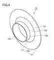
Fig. 4 is a perspective view schematically representing a configuration of a first protruding member according to an embodiment of the present invention. -
Fig. 5 is a partial broken away side view showing in enlargement a configuration in the neighborhood of a partition ofFig. 2 . -
Fig. 6 is a sectional view taken along line VI-VI ofFig. 5 . -
Fig. 7 schematically represents a configuration in the neighborhood of first to third flanges viewed from the first end side of the first to third flanges according to an embodiment of the present invention. -
Fig. 8 schematically represents a configuration in the neighborhood of first to third flanges viewed from the surface side of the first to third flanges according to an embodiment of the present invention. - Embodiments of the present invention will be described hereinafter with reference to the drawings.
- First, a configuration of a work vehicle according to an embodiment of the present invention will be described. Description based on a wheel loader that is an example of a work vehicle to which the concept of the present invention can be applied will be provided.
- Referring to
Fig. 1 , awheel loader 1 of the present embodiment mainly includes arear body 2, afront body 3, andwork machinery 4. Each of the sides offront body 3 has afront wheel 5a attached. Each of the sides ofrear body 2 has arear wheel 5b attached. -
Rear body 2 andfront body 3 are attached horizontally swingable by a center pin (not shown) to constitute an articulate structure. Specifically,rear body 2 andfront body 3 are coupled by left and right steering cylinders (not shown) constituting a pair. The left and right steering cylinders are configured to elongate and contract such thatrear body 2 andfront body 3 sway left and right about the center pin for steering.Rear body 2 andfront body 3 constitute the body part ofwheel loader 1. -
Work machinery 4 is attached in front offront body 3.Work machinery 4 includes aboom 4a attached tofront body 3 with its proximal end swingable, and abucket 4b attached to the leading end ofboom 4a in a swingable manner.Front body 3 is attached toboom 4a by a pair ofboom cylinders boom 4a sways byboom cylinders -
Work machinery 4 includes abell crank 4d supported swingably byboom 4a at substantially the central region, abucket cylinder 4e coupling the proximal end ofbell crank 4d withfront body 3, and alink 4f coupling the leading end ofbell crank 4d withbucket 4b. The elongation and contraction ofbucket cylinder 4e causesbucket 4b to sway. - An
engine room 6a is arranged at the back ofrear body 2. Ahydraulic oil tank 7 is arranged in front ofengine room 6a. Acab 8 where the operator enters to operatewheel loader 1 is located in front ofhydraulic oil tank 7. The front and back as well as the left and right ofwheel loader 1 are based on the operator sitting incab 8 as the reference. Atop panel 2a is arranged at the top face ofrear body 2.Top panel 2a is located aboveengine room 6a in the state wherewheel loader 1 is situated on a horizontal ground G. - Referring to
Figs. 2 and3 , anengine 11 and acooling device 12 are arranged inengine room 6a.Cooling device 12 includes aCAC device 12a, a radiator (engine coolant cooling device) 12b, and an oil cooler (hydraulic oil cooling device) 12c.CAC device 12a,radiator 12b and oil cooler 12c are arranged in line at the back ofengine room 6a. -
Engine room 6a is divided by apartition 13.Partition 13 is arranged betweenengine 11 andcooling device 12.Partition 13 includes a first throughhole 13a. CAC hose (first hose) 14 and a radiator hose (second hose) 15 pass through first throughhole 13a to connectengine 11 withcooling device 12. Specifically,CAC hose 14 passes through first throughhole 13a to connectengine 11 withCAC device 12a.Radiator hose 15 passes through first throughhole 13a to connectengine 11 withradiator 12b. A hydraulic oil hose not shown is connected to oil cooler 12c. -
Top panel 2a is arranged aboveengine 11,cooling device 12 andpartition 13.Top panel 2a includes a vent H provided aboveCAC hose 14 andradiator hose 15 at the side of coolingdevice 12 relative to partition 13. A plurality of vents H are formed. - In the proximity of
partition 13 are attached a first protrudingmember 16 including a flange and a second protrudingmember 17 including a flange atCAC hose 14. A third protrudingmember 18 having a flange is attached atradiator hose 15. A plurality of vents H are arranged above first to third protruding members 16-18. - In
engine room 6a, an exhaust system filter (DPF: diesel particulate filter) 21 and anintake system filter 22 are arranged. Each ofexhaust system filter 21 andintake system filter 22 is connected toengine 11.Exhaust system filter 21 is connected to anexhaust pipe 23 arranged abovetop panel 2a.Intake system filter 22 is connected to anair cleaner 24 arranged abovetop panel 2a. Furthermore, a coolingfan 19 is arranged behind coolingdevice 12. - Referring mainly to
Fig. 4 , a configuration of first to third protruding members 16-18 will be described in detail. - Referring to
Fig. 4 , a configuration of first protrudingmember 16 and second protrudingmember 17 will be described. Since first and second protrudingmembers member 16 will be described representative thereof. The configuration of second protrudingmember 17 will not be described repeatedly, unless noted otherwise. - First protruding
member 15 includes aflat section 161, ataper section 162, and acylindrical section 163.Flat section 161 is arranged at the outer circumferential end of first protrudingmember 16.Flat section 161 has a disk shape.Taper section 162 is located betweenflat section 161 andcylindrical section 163.Taper section 162 is inclined such that the diameter becomes smaller towardscylindrical section 163.Cylindrical section 163 protrudes in a direction where the diameter oftaper section 162 becomes smaller thanflat section 161.Cylindrical section 163 takes a cylindrical shape.Flat section 161 and the portion oftaper section 162 in the radial direction constitutefirst flange 16a. First protrudingmember 16 has aninsert hole 16b at the central area. - The elements in each of first to
third flanges 16a-18a may be formed integrally as each of protruding members 16-18. - Third protruding
member 18 has a similar configuration except that its cylindrical section is longer than the cylindrical section of first and second protrudingmembers - The state where first and second protruding
members CAC hose 14 and third protrudingmember 18 is attached toradiator hose 15 will be described hereinafter with reference toFigs. 5-8 . - Referring to
Figs. 5 and6 , abracket 131 and acover 133 are attached to partition 13.Bracket 131 protrudes frompartition 13 towards the side of coolingdevice 12. For the purpose ofCAC hose 14 andradiator hose 15 to communicate withengine 11, a first throughhole 13a is formed atpartition 13 and a second throughhole 13b is formed atbracket 131 at an upper portion.Protection members hole 13b atbracket 131. -
CAC hose 14 having first and second protrudingmembers radiator hose 15 having third protrudingmember 18 attached run along the inner side ofbracket 131 from second throughhole 13b to be connected toengine 11. - Above second through
hole 13b are located first tothird flanges 16a - 18b of first to third protruding members 16-18.First flange 16a andsecond flange 17a are arranged spaced apart frompartition 13 at the side of cooling device 12 (refer toFig. 2 ).First flange 16a andsecond flange 17a are formed at the outer circumferential face ofCAC hose 14 so as to protrude outward ofCAC hose 14.First flange 16a andsecond flange 17a are arranged spaced apart from each other in the longitudinal direction ofCAC hose 14. -
Third flange 18a is arranged spaced apart frompartition 13 at the side of coolingdevice 12.Third flange 18a is formed at the outer circumferential face ofradiator hose 15 so as to protrude outward ofradiator hose 15. - Each of first to
third flanges 16a-18a tilts downwards from thepartition 13 side towards the coolingdevice 12 side. - A
cover 133 is provided abovethird flange 18a at thepartition 13 side. Cover 133 has a curved section arranged at the outer side ofCAC hose 14 andradiator hose 15. Aprotection member 133a is attached to this curved section. - Referring to
Fig. 7 ,CAC hose 14 is inserted into throughhole 16b of first protrudingmember 16 and throughhole 17b of second protrudingmember 17 to be press-bonded. There is no gap between first and second protrudingmembers CAC hose 14. Furthermore,radiator hose 15 is inserted into throughhole 18b of third protrudingmember 18 to be press-bonded. There is no gap between third protrudingmember 18 andradiator hose 15. Accordingly, the running of rain water from throughhole 16b of first protrudingmember 16, throughhole 17b of second protrudingmember 17, and throughhole 18b of third protrudingmember 18 towards the inner side of second throughhole 13b ofpartition 13 can be prevented. -
Third flange 18a is arranged to overlap withfirst flange 16a andsecond flange 17a by extending in a region R sandwiched betweenfirst flange 16a andsecond flange 17a. In the present embodiment,first flange 16a andsecond flange 17a are arranged in parallel.Third flange 18a is arranged parallel tofirst flange 16a andsecond flange 17a. First tothird flanges 16a - 18a are arranged parallel to the opening of second throughhole 13b. -
Fig. 7 is a view from the direction of arrow D1 inFig. 5 .Fig. 8 is a view from the direction of arrow D2 inFig. 5 . Referring toFigs. 7 and8 , first tothird flanges 16a-18a are provided such that a projection shape E of first tothird flanges 16a-18a from a mutually overlapping direction (hereinafter, referred to as "projection shape") covers second throughhole 13b entirely. Shape E corresponding to the projection of first tothird flanges 16a-18a from a direction where they overlap each other covers the opening of second throughhole 13b entirely. Projection shape E inFig. 8 is indicated more slightly at the outer side than the actual projection shape for the sake of facilitating observation. - First to
third flanges 16a-18a each have a circular outer shape. Viewing from the direction where the flanges overlap with each other, each of first andsecond flanges third flange 18a by a length greater than or equal to half a dimension corresponding to the dimension in the radial direction minus the radius of the hose (the dimension of the flange alone). Further,first flange 16a andsecond flange 17a are arranged spaced apart from each other in the longitudinal direction ofCAC hose 14.Third flange 18a arranged between first andsecond flanges second flanges second flanges radiator hose 15, i.e. do not form contact withradiator hose 15.Third flange 18a is spaced apart fromCAC hose 14, i.e. does not form contact withCAC hose 14. First protrudingmember 16 andsecond flange 17a may be formed unitary. - A functional advantage of the present embodiment will be described hereinafter.
- At
wheel loader 1 of the present embodiment as shown inFig. 7 ,third flange 18a is arranged to overlap withfirst flange 16a andsecond flange 17a by extending in a region R sandwiched betweenfirst flange 16a andsecond flange 17a. Therefore, first tothird flanges 16a-18a serve to prevent rain water running inside from entering theengine 11 side (refer toFig. 2 ) along the first and second hoses.First flange 16a andsecond flange 17a are attached toCAC hose 14, whereasthird flange 18a is attached toradiator hose 15. In other words, first tothird flanges 16a-18a are attached individually toCAC hose 14 andradiator hose 15. Therefore,CAC hose 14 andradiator hose 15 can be connected individually withengine 11. Accordingly, the connection ofCAC hose 14 andradiator hose 15 withengine 11 can be facilitated. - At
wheel loader 1 of the present embodiment as shown inFig. 5 ,CAC hose 14 andradiator hose 15 passed through first throughhole 13a inpartition 13. Therefore,CAC hose 14 andradiator hose 15 can connectengine 11 withcooling device 12 at the shortest distance without the need to avoidpartition 13. - At
wheel loader 1 of the present embodiment as shown inFig. 5 , each of first tothird flanges 16a-18a of first to third protruding members 16-18 tilts downwards from the side ofpartition 13 to the side of cooling device 12 (refer toFig. 2 ). Therefore, rain water adhering to first tothird flanges 16a-18a run to the side of coolingdevice 12. Accordingly, rain water adhering to first tothird flanges 16a-18a can be prevented from running towards the side ofengine 11. - At
wheel loader 1 of the present embodiment,bracket 131 includes a second throughhole 13b at the upper portion. Therefore, first tothird flanges 16a-18a can be arranged facing upwards. - At
wheel loader 1 of the present embodiment as shown inFig. 8 , first tothird flanges 16a-18a are provided such that a projection shape E of first tothird flanges 16a-18a from a mutually overlapping direction covers second throughhole 13b entirely. Accordingly, the intrusion of the rain water passing through second throughhole 13b from between the rims of first tothird flanges 16a-18a and the second throughhole 13b to enter theengine 11 side (refer toFig. 5 ) can be prevented. - At
wheel loader 1 of the present embodiment as shown inFig. 8 , each of first andsecond flanges third flange 18a by a length greater than or equal to half the width of each flange, when viewed from the mutually overlapping direction. Therefore, the overlapping area betweenfirst flange 16a andthird flange 18a and the overlapping area betweensecond flange 17a andthird flange 18a can be ensured reliably. Accordingly, the intrusion of rain water from betweenfirst flange 16a andthird flange 18a and from betweensecond flange 17a andthird flange 18a into theengine 11 side (refer toFig. 2 ) can be prevented more reliably. - At
wheel loader 1 of the present embodiment,third flange 18a is spaced apart fromfirst flange 16a in the longitudinal direction of the second hose, and spaced apart fromsecond flange 17a in the longitudinal direction ofradiator hose 15. First andsecond flanges radiator hose 15 in the radial direction, andthird flange 18a is spaced apart fromCAC hose 14 in the radial direction. Accordingly, accumulation of rain water at the first to third flanges can be prevented. - At
wheel loader 1 of the present embodiment as shown inFig. 3 ,top panel 2a includes a vent H provided aboveCAC hose 14 andradiator hose 15 at the side of coolingdevice 12 relative to partition 13. Therefore, first tothird flanges 16a-18a serve to prevent the rain water running in through vent H provided aboveCAC hose 14 andradiator hose 15 from entering theengine 11 side (refer toFig. 2 ) alongCAC hose 14 andradiator hose 15. -
Wheel loader 1 of the present embodiment is formed integrally with protruding members 16-18, respectively. Therefore, the assembly is facilitated. - It is to be understood that the embodiments disclosed herein are only by way of example, and not to be taken by way of limitation. The scope of the present invention is not limited by the description above, but rather by the terms of the appended claims, and is intended to include any modifications within the scope and meaning equivalent to the terms of the claims.
- The present invention may be applied particularly advantageously to a work vehicle including a partition arranged between an engine and a cooling device.
- 1 wheel loader; 2 rear body; 2a top panel; 3 front body; 4 work machinery; 5a front wheel; 5b rear wheel; 6a engine room; 7 hydraulic oil tank; 8 cab; 11 engine; 12 cooling device; 12a CAC device; 12b radiator (engine coolant cooling device); 12c oil cooler (hydraulic oil cooling device); 13 partition; 13a first through hole; 13b second through hole; 14 CAC hose; 15 radiator hose; 16-18 first-third protruding member; 16a-18a first-third flange; 19 cooling fan; 21 exhaust system filter; 22 intake system filter; 23 exhaust pipe; 24 air cleaner; 131 bracket; 133 cover; 161, 171, 181 flat section; 162, 172, 182 taper section; 163, 173, 183 cylindrical section; E projection shape; E1 first end; E2 second end; G ground; H vent
Claims (9)
- A work vehicle comprising:an engine;a cooling device;first and second hoses arranged between said engine and said cooling device for connecting said engine and said cooling device;first and second flanges formed at an outer circumferential face of said first hose to protrude outward of said first hose, and arranged spaced apart from each other; anda third flange formed at an outer circumferential face of said second hose to protrude outward of said second hose,said third flange arranged to overlap with said first and second flanges by extending in a region sandwiched between said first flange and said second flange.
- The work vehicle according to claim 1, wherein
a partition having a first through hole is arranged between said engine and said cooling device, and
said first hose and said second hose pass through said first through hole in the partition. - The work vehicle according to claim 2, wherein each of said first to third flanges tilts downwards from said partition side towards said cooling device side.
- The work vehicle according to claim 2 or 3, wherein
said partition further includes a bracket at said cooling device side, and
said bracket includes a second through hole at an upper portion. - The work vehicle according to claim 4, wherein said first to third flanges are provided such that a projection shape of said first to third flanges from a mutually overlapping direction covers said second through hole entirely.
- The work vehicle according to any one of claims 1-5 wherein
each of said first to third flanges has a circular outer shape, and
each of said first and second flanges overlaps with said third flange by a length greater than or equal to half a width of each relevant flange, when viewed from a mutually overlapping direction. - The work vehicle according to any one of claims 1-6, wherein
said first flange and said second flange are arranged spaced apart from each other in a longitudinal direction of said first hose,
said third flange arranged between said first and second flanges is spaced apart from said first flange in a longitudinal direction of said second hose, and spaced apart from said second flange in a longitudinal direction of said second hose,
said first and second flanges are spaced apart from said second hose in a radial direction, and
said third flange is spaced apart from said first hose in a radial direction. - The work vehicle according to any one of claims 2-4, further comprising a top panel arranged above said engine, said cooling device, and said partition,
wherein said top panel has a vent provided above said first and second hoses at said cooling device side relative to said partition. - The work vehicle according to any one of claims 1-8, wherein elements in each of said first to third flanges are formed integrally as each of first to third protruding members.
Applications Claiming Priority (2)
| Application Number | Priority Date | Filing Date | Title |
|---|---|---|---|
| JP2012165757A JP5130410B1 (en) | 2012-07-26 | 2012-07-26 | Work vehicle |
| PCT/JP2012/070453 WO2014016973A1 (en) | 2012-07-26 | 2012-08-10 | Working vehicle |
Publications (3)
| Publication Number | Publication Date |
|---|---|
| EP2712751A1 true EP2712751A1 (en) | 2014-04-02 |
| EP2712751A4 EP2712751A4 (en) | 2014-08-13 |
| EP2712751B1 EP2712751B1 (en) | 2015-06-10 |
Family
ID=47693007
Family Applications (1)
| Application Number | Title | Priority Date | Filing Date |
|---|---|---|---|
| EP12805504.3A Active EP2712751B1 (en) | 2012-07-26 | 2012-08-10 | Working vehicle |
Country Status (5)
| Country | Link |
|---|---|
| US (1) | US8857548B2 (en) |
| EP (1) | EP2712751B1 (en) |
| JP (1) | JP5130410B1 (en) |
| CN (1) | CN103702853B (en) |
| WO (1) | WO2014016973A1 (en) |
Families Citing this family (11)
| Publication number | Priority date | Publication date | Assignee | Title |
|---|---|---|---|---|
| JP5449517B1 (en) * | 2012-12-20 | 2014-03-19 | 株式会社小松製作所 | Work vehicle |
| US9989252B2 (en) * | 2013-08-22 | 2018-06-05 | Noritz Corporation | Exhaust adapter, exhaust structure for water heater, and method for installing exhaust adapter |
| DE112013000149B4 (en) * | 2013-09-25 | 2018-02-15 | Komatsu Ltd. | working vehicle |
| US9033081B1 (en) | 2014-03-31 | 2015-05-19 | Komatsu Ltd. | Work vehicle |
| EP2891570B1 (en) | 2014-03-31 | 2017-12-06 | Komatsu Ltd. | Work vehicle with an engine compartment cooling unit |
| JP5607279B1 (en) | 2014-03-31 | 2014-10-15 | 株式会社小松製作所 | Work vehicle |
| CN104302500B (en) | 2014-03-31 | 2018-02-02 | 株式会社小松制作所 | Working truck |
| CN104220288B (en) * | 2014-06-30 | 2017-05-24 | 株式会社小松制作所 | Utility vehicle |
| WO2016027307A1 (en) | 2014-08-19 | 2016-02-25 | 株式会社小松製作所 | Work vehicle |
| JP6009063B2 (en) | 2014-08-19 | 2016-10-19 | 株式会社小松製作所 | Work vehicle |
| US9683527B2 (en) * | 2015-11-09 | 2017-06-20 | Kyle Tallman | Snorkel apparatus with auxiliary air tube supports |
Citations (3)
| Publication number | Priority date | Publication date | Assignee | Title |
|---|---|---|---|---|
| US20100283278A1 (en) * | 2008-07-31 | 2010-11-11 | Hitachi Construction Machinery Co., Ltd. | Construction machine |
| EP2311681A1 (en) * | 2009-10-16 | 2011-04-20 | Hitachi Construction Machinery Co., Ltd. | Construction machine |
| US20120138379A1 (en) * | 2010-08-02 | 2012-06-07 | Komatsu Ltd. | Work vehicle |
Family Cites Families (22)
| Publication number | Priority date | Publication date | Assignee | Title |
|---|---|---|---|---|
| US3765629A (en) * | 1971-04-16 | 1973-10-16 | Standard Oil Co | Conduit support and spacer means |
| US3860978A (en) * | 1973-05-18 | 1975-01-21 | Paul H Wirth | Time saving drain assembly for sinks, bathtubs, etc. |
| US3899005A (en) * | 1973-08-06 | 1975-08-12 | Fiberglass Resources Corp | Modular duct system for elongated flexible members such as telephone cable or the like |
| JPH0628227A (en) | 1992-06-09 | 1994-02-04 | Nec Corp | Automatic confirmation system for file area securing result |
| JP2593642Y2 (en) * | 1992-09-09 | 1999-04-12 | 油谷重工株式会社 | Piping structure of oil cooler for construction machinery |
| US5398977A (en) * | 1993-05-06 | 1995-03-21 | Dayco Products, Inc. | Concentric hose coupling with cuff assembly surrounding an end of the outer hose |
| JPH0814243A (en) | 1994-06-28 | 1996-01-16 | Piolax Inc | Connection structure of grommet |
| JPH0828266A (en) | 1994-07-13 | 1996-01-30 | Komatsu Ltd | Cooling device for engine |
| JPH1122572A (en) * | 1997-06-30 | 1999-01-26 | Suzuki Motor Corp | Resonator structure for internal combustion engine |
| JP4061063B2 (en) | 2001-12-14 | 2008-03-12 | 新キャタピラー三菱株式会社 | Construction machinery |
| JP4140424B2 (en) | 2003-04-09 | 2008-08-27 | 株式会社デンソー | Piping seal material |
| US7845338B2 (en) * | 2003-10-17 | 2010-12-07 | Honeywell International, Inc. | Internal bypass exhaust gas cooler |
| JP4455924B2 (en) * | 2004-04-21 | 2010-04-21 | 株式会社パイオラックス | Pipe fitting |
| JP4523401B2 (en) * | 2004-12-28 | 2010-08-11 | 日立建機株式会社 | Work machine |
| JP2006207247A (en) | 2005-01-27 | 2006-08-10 | Shin Caterpillar Mitsubishi Ltd | Protective wall insertion structure of hose |
| JP4467552B2 (en) | 2006-10-16 | 2010-05-26 | 株式会社小松製作所 | Construction machine cooling system |
| US7699356B2 (en) * | 2007-05-10 | 2010-04-20 | Craig Assgembly, Inc. | Quick connector for fluid conduit |
| JP5286736B2 (en) | 2007-10-09 | 2013-09-11 | 日産自動車株式会社 | Grommet |
| US8245733B2 (en) * | 2009-11-12 | 2012-08-21 | E I Du Pont De Nemours And Company | Clip for a pipe or duct |
| JP2011137378A (en) * | 2009-12-25 | 2011-07-14 | Mitsubishi Agricultural Machinery Co Ltd | Working vehicle equipped with engine room |
| US8047328B1 (en) * | 2010-06-09 | 2011-11-01 | Mark Milewicz | Plastic muffler and method for making same |
| US8875743B2 (en) * | 2012-08-24 | 2014-11-04 | Nordson Corporation | Hanger and method for routing a hot melt hose |
-
2012
- 2012-07-26 JP JP2012165757A patent/JP5130410B1/en not_active Expired - Fee Related
- 2012-08-10 WO PCT/JP2012/070453 patent/WO2014016973A1/en active Application Filing
- 2012-08-10 CN CN201280001927.6A patent/CN103702853B/en active Active
- 2012-08-10 EP EP12805504.3A patent/EP2712751B1/en active Active
- 2012-08-10 US US13/807,795 patent/US8857548B2/en active Active
Patent Citations (3)
| Publication number | Priority date | Publication date | Assignee | Title |
|---|---|---|---|---|
| US20100283278A1 (en) * | 2008-07-31 | 2010-11-11 | Hitachi Construction Machinery Co., Ltd. | Construction machine |
| EP2311681A1 (en) * | 2009-10-16 | 2011-04-20 | Hitachi Construction Machinery Co., Ltd. | Construction machine |
| US20120138379A1 (en) * | 2010-08-02 | 2012-06-07 | Komatsu Ltd. | Work vehicle |
Non-Patent Citations (1)
| Title |
|---|
| See also references of WO2014016973A1 * |
Also Published As
| Publication number | Publication date |
|---|---|
| JP5130410B1 (en) | 2013-01-30 |
| CN103702853B (en) | 2015-06-10 |
| JP2014025254A (en) | 2014-02-06 |
| EP2712751A4 (en) | 2014-08-13 |
| US8857548B2 (en) | 2014-10-14 |
| WO2014016973A1 (en) | 2014-01-30 |
| CN103702853A (en) | 2014-04-02 |
| EP2712751B1 (en) | 2015-06-10 |
| US20140190577A1 (en) | 2014-07-10 |
Similar Documents
| Publication | Publication Date | Title |
|---|---|---|
| EP2712751B1 (en) | Working vehicle | |
| US8919486B2 (en) | Hydraulic excavator | |
| JP5033226B2 (en) | Work vehicle | |
| US20160082831A1 (en) | Industrial vehicle | |
| EP2821613B1 (en) | Ventilation structure for engine compartment | |
| EP2842783B1 (en) | Work vehicle | |
| EP2918436B1 (en) | Vehicle body cover and work vehicle | |
| US20160168821A1 (en) | Work vehicle | |
| US8931266B2 (en) | Work vehicle and method for manufacturing the same | |
| US8827021B1 (en) | Bulldozer | |
| US9347350B2 (en) | Engine unit | |
| US9556586B2 (en) | Working vehicle | |
| US9528244B2 (en) | Work vehicle | |
| EP3210858B1 (en) | Tractor bonnet | |
| US10029731B2 (en) | Work vehicle | |
| JP5645130B2 (en) | Piping structure of a turbocharger for vehicles | |
| CN106184089A (en) | Bumper | |
| JP7105686B2 (en) | work vehicle | |
| US8919817B2 (en) | Bulldozer | |
| JP2016188558A (en) | Working machine | |
| JP2020159231A (en) | Exhaust diffusion structure | |
| JP2013167097A (en) | Construction machine | |
| US20160265191A1 (en) | Bulldozer | |
| GB2557879A (en) | Hitch assembly for machine |
Legal Events
| Date | Code | Title | Description |
|---|---|---|---|
| PUAI | Public reference made under article 153(3) epc to a published international application that has entered the european phase |
Free format text: ORIGINAL CODE: 0009012 |
|
| 17P | Request for examination filed |
Effective date: 20130107 |
|
| AK | Designated contracting states |
Kind code of ref document: A1 Designated state(s): AL AT BE BG CH CY CZ DE DK EE ES FI FR GB GR HR HU IE IS IT LI LT LU LV MC MK MT NL NO PL PT RO RS SE SI SK SM TR |
|
| A4 | Supplementary search report drawn up and despatched |
Effective date: 20140716 |
|
| RIC1 | Information provided on ipc code assigned before grant |
Ipc: E02F 9/00 20060101ALI20140710BHEP Ipc: F01P 11/04 20060101ALI20140710BHEP Ipc: B60K 11/04 20060101AFI20140710BHEP Ipc: E02F 9/08 20060101ALI20140710BHEP |
|
| RIC1 | Information provided on ipc code assigned before grant |
Ipc: F01P 11/04 20060101ALI20141201BHEP Ipc: E02F 9/00 20060101ALI20141201BHEP Ipc: B60K 11/04 20060101AFI20141201BHEP Ipc: E02F 9/08 20060101ALI20141201BHEP Ipc: F16L 3/23 20060101ALI20141201BHEP |
|
| GRAP | Despatch of communication of intention to grant a patent |
Free format text: ORIGINAL CODE: EPIDOSNIGR1 |
|
| DAX | Request for extension of the european patent (deleted) | ||
| INTG | Intention to grant announced |
Effective date: 20150205 |
|
| GRAS | Grant fee paid |
Free format text: ORIGINAL CODE: EPIDOSNIGR3 |
|
| GRAA | (expected) grant |
Free format text: ORIGINAL CODE: 0009210 |
|
| AK | Designated contracting states |
Kind code of ref document: B1 Designated state(s): AL AT BE BG CH CY CZ DE DK EE ES FI FR GB GR HR HU IE IS IT LI LT LU LV MC MK MT NL NO PL PT RO RS SE SI SK SM TR |
|
| REG | Reference to a national code |
Ref country code: GB Ref legal event code: FG4D |
|
| REG | Reference to a national code |
Ref country code: CH Ref legal event code: EP |
|
| REG | Reference to a national code |
Ref country code: AT Ref legal event code: REF Ref document number: 730742 Country of ref document: AT Kind code of ref document: T Effective date: 20150715 |
|
| REG | Reference to a national code |
Ref country code: DE Ref legal event code: R096 Ref document number: 602012007959 Country of ref document: DE |
|
| REG | Reference to a national code |
Ref country code: IE Ref legal event code: FG4D |
|
| REG | Reference to a national code |
Ref country code: SE Ref legal event code: TRGR |
|
| PG25 | Lapsed in a contracting state [announced via postgrant information from national office to epo] |
Ref country code: LT Free format text: LAPSE BECAUSE OF FAILURE TO SUBMIT A TRANSLATION OF THE DESCRIPTION OR TO PAY THE FEE WITHIN THE PRESCRIBED TIME-LIMIT Effective date: 20150610 Ref country code: NO Free format text: LAPSE BECAUSE OF FAILURE TO SUBMIT A TRANSLATION OF THE DESCRIPTION OR TO PAY THE FEE WITHIN THE PRESCRIBED TIME-LIMIT Effective date: 20150910 Ref country code: FI Free format text: LAPSE BECAUSE OF FAILURE TO SUBMIT A TRANSLATION OF THE DESCRIPTION OR TO PAY THE FEE WITHIN THE PRESCRIBED TIME-LIMIT Effective date: 20150610 Ref country code: ES Free format text: LAPSE BECAUSE OF FAILURE TO SUBMIT A TRANSLATION OF THE DESCRIPTION OR TO PAY THE FEE WITHIN THE PRESCRIBED TIME-LIMIT Effective date: 20150610 |
|
| REG | Reference to a national code |
Ref country code: AT Ref legal event code: MK05 Ref document number: 730742 Country of ref document: AT Kind code of ref document: T Effective date: 20150610 |
|
| REG | Reference to a national code |
Ref country code: NL Ref legal event code: MP Effective date: 20150610 |
|
| PG25 | Lapsed in a contracting state [announced via postgrant information from national office to epo] |
Ref country code: LV Free format text: LAPSE BECAUSE OF FAILURE TO SUBMIT A TRANSLATION OF THE DESCRIPTION OR TO PAY THE FEE WITHIN THE PRESCRIBED TIME-LIMIT Effective date: 20150610 Ref country code: GR Free format text: LAPSE BECAUSE OF FAILURE TO SUBMIT A TRANSLATION OF THE DESCRIPTION OR TO PAY THE FEE WITHIN THE PRESCRIBED TIME-LIMIT Effective date: 20150911 Ref country code: RS Free format text: LAPSE BECAUSE OF FAILURE TO SUBMIT A TRANSLATION OF THE DESCRIPTION OR TO PAY THE FEE WITHIN THE PRESCRIBED TIME-LIMIT Effective date: 20150610 Ref country code: BG Free format text: LAPSE BECAUSE OF FAILURE TO SUBMIT A TRANSLATION OF THE DESCRIPTION OR TO PAY THE FEE WITHIN THE PRESCRIBED TIME-LIMIT Effective date: 20150910 |
|
| PG25 | Lapsed in a contracting state [announced via postgrant information from national office to epo] |
Ref country code: EE Free format text: LAPSE BECAUSE OF FAILURE TO SUBMIT A TRANSLATION OF THE DESCRIPTION OR TO PAY THE FEE WITHIN THE PRESCRIBED TIME-LIMIT Effective date: 20150610 |
|
| PG25 | Lapsed in a contracting state [announced via postgrant information from national office to epo] |
Ref country code: IS Free format text: LAPSE BECAUSE OF FAILURE TO SUBMIT A TRANSLATION OF THE DESCRIPTION OR TO PAY THE FEE WITHIN THE PRESCRIBED TIME-LIMIT Effective date: 20151010 Ref country code: RO Free format text: LAPSE BECAUSE OF NON-PAYMENT OF DUE FEES Effective date: 20150610 Ref country code: CZ Free format text: LAPSE BECAUSE OF FAILURE TO SUBMIT A TRANSLATION OF THE DESCRIPTION OR TO PAY THE FEE WITHIN THE PRESCRIBED TIME-LIMIT Effective date: 20150610 Ref country code: PL Free format text: LAPSE BECAUSE OF FAILURE TO SUBMIT A TRANSLATION OF THE DESCRIPTION OR TO PAY THE FEE WITHIN THE PRESCRIBED TIME-LIMIT Effective date: 20150610 Ref country code: AT Free format text: LAPSE BECAUSE OF FAILURE TO SUBMIT A TRANSLATION OF THE DESCRIPTION OR TO PAY THE FEE WITHIN THE PRESCRIBED TIME-LIMIT Effective date: 20150610 Ref country code: PT Free format text: LAPSE BECAUSE OF FAILURE TO SUBMIT A TRANSLATION OF THE DESCRIPTION OR TO PAY THE FEE WITHIN THE PRESCRIBED TIME-LIMIT Effective date: 20151012 Ref country code: SK Free format text: LAPSE BECAUSE OF FAILURE TO SUBMIT A TRANSLATION OF THE DESCRIPTION OR TO PAY THE FEE WITHIN THE PRESCRIBED TIME-LIMIT Effective date: 20150610 |
|
| REG | Reference to a national code |
Ref country code: DE Ref legal event code: R097 Ref document number: 602012007959 Country of ref document: DE |
|
| PG25 | Lapsed in a contracting state [announced via postgrant information from national office to epo] |
Ref country code: MC Free format text: LAPSE BECAUSE OF FAILURE TO SUBMIT A TRANSLATION OF THE DESCRIPTION OR TO PAY THE FEE WITHIN THE PRESCRIBED TIME-LIMIT Effective date: 20150610 Ref country code: LU Free format text: LAPSE BECAUSE OF FAILURE TO SUBMIT A TRANSLATION OF THE DESCRIPTION OR TO PAY THE FEE WITHIN THE PRESCRIBED TIME-LIMIT Effective date: 20150810 |
|
| REG | Reference to a national code |
Ref country code: CH Ref legal event code: PL |
|
| PLBE | No opposition filed within time limit |
Free format text: ORIGINAL CODE: 0009261 |
|
| STAA | Information on the status of an ep patent application or granted ep patent |
Free format text: STATUS: NO OPPOSITION FILED WITHIN TIME LIMIT |
|
| PG25 | Lapsed in a contracting state [announced via postgrant information from national office to epo] |
Ref country code: CH Free format text: LAPSE BECAUSE OF NON-PAYMENT OF DUE FEES Effective date: 20150831 Ref country code: LI Free format text: LAPSE BECAUSE OF NON-PAYMENT OF DUE FEES Effective date: 20150831 Ref country code: DK Free format text: LAPSE BECAUSE OF FAILURE TO SUBMIT A TRANSLATION OF THE DESCRIPTION OR TO PAY THE FEE WITHIN THE PRESCRIBED TIME-LIMIT Effective date: 20150610 Ref country code: IT Free format text: LAPSE BECAUSE OF FAILURE TO SUBMIT A TRANSLATION OF THE DESCRIPTION OR TO PAY THE FEE WITHIN THE PRESCRIBED TIME-LIMIT Effective date: 20150610 |
|
| 26N | No opposition filed |
Effective date: 20160311 |
|
| PG25 | Lapsed in a contracting state [announced via postgrant information from national office to epo] |
Ref country code: SI Free format text: LAPSE BECAUSE OF FAILURE TO SUBMIT A TRANSLATION OF THE DESCRIPTION OR TO PAY THE FEE WITHIN THE PRESCRIBED TIME-LIMIT Effective date: 20150610 |
|
| REG | Reference to a national code |
Ref country code: IE Ref legal event code: MM4A |
|
| REG | Reference to a national code |
Ref country code: FR Ref legal event code: ST Effective date: 20160429 |
|
| PG25 | Lapsed in a contracting state [announced via postgrant information from national office to epo] |
Ref country code: IE Free format text: LAPSE BECAUSE OF NON-PAYMENT OF DUE FEES Effective date: 20150810 |
|
| PG25 | Lapsed in a contracting state [announced via postgrant information from national office to epo] |
Ref country code: FR Free format text: LAPSE BECAUSE OF NON-PAYMENT OF DUE FEES Effective date: 20150831 |
|
| PG25 | Lapsed in a contracting state [announced via postgrant information from national office to epo] |
Ref country code: BE Free format text: LAPSE BECAUSE OF FAILURE TO SUBMIT A TRANSLATION OF THE DESCRIPTION OR TO PAY THE FEE WITHIN THE PRESCRIBED TIME-LIMIT Effective date: 20150610 |
|
| PG25 | Lapsed in a contracting state [announced via postgrant information from national office to epo] |
Ref country code: MT Free format text: LAPSE BECAUSE OF FAILURE TO SUBMIT A TRANSLATION OF THE DESCRIPTION OR TO PAY THE FEE WITHIN THE PRESCRIBED TIME-LIMIT Effective date: 20150610 |
|
| GBPC | Gb: european patent ceased through non-payment of renewal fee |
Effective date: 20160810 |
|
| PG25 | Lapsed in a contracting state [announced via postgrant information from national office to epo] |
Ref country code: SM Free format text: LAPSE BECAUSE OF FAILURE TO SUBMIT A TRANSLATION OF THE DESCRIPTION OR TO PAY THE FEE WITHIN THE PRESCRIBED TIME-LIMIT Effective date: 20150610 Ref country code: HU Free format text: LAPSE BECAUSE OF FAILURE TO SUBMIT A TRANSLATION OF THE DESCRIPTION OR TO PAY THE FEE WITHIN THE PRESCRIBED TIME-LIMIT; INVALID AB INITIO Effective date: 20120810 |
|
| PG25 | Lapsed in a contracting state [announced via postgrant information from national office to epo] |
Ref country code: CY Free format text: LAPSE BECAUSE OF FAILURE TO SUBMIT A TRANSLATION OF THE DESCRIPTION OR TO PAY THE FEE WITHIN THE PRESCRIBED TIME-LIMIT Effective date: 20150610 Ref country code: NL Free format text: LAPSE BECAUSE OF FAILURE TO SUBMIT A TRANSLATION OF THE DESCRIPTION OR TO PAY THE FEE WITHIN THE PRESCRIBED TIME-LIMIT Effective date: 20150610 |
|
| PG25 | Lapsed in a contracting state [announced via postgrant information from national office to epo] |
Ref country code: GB Free format text: LAPSE BECAUSE OF NON-PAYMENT OF DUE FEES Effective date: 20160810 Ref country code: HR Free format text: LAPSE BECAUSE OF FAILURE TO SUBMIT A TRANSLATION OF THE DESCRIPTION OR TO PAY THE FEE WITHIN THE PRESCRIBED TIME-LIMIT Effective date: 20150610 |
|
| PG25 | Lapsed in a contracting state [announced via postgrant information from national office to epo] |
Ref country code: MK Free format text: LAPSE BECAUSE OF FAILURE TO SUBMIT A TRANSLATION OF THE DESCRIPTION OR TO PAY THE FEE WITHIN THE PRESCRIBED TIME-LIMIT Effective date: 20150610 Ref country code: TR Free format text: LAPSE BECAUSE OF FAILURE TO SUBMIT A TRANSLATION OF THE DESCRIPTION OR TO PAY THE FEE WITHIN THE PRESCRIBED TIME-LIMIT Effective date: 20150610 |
|
| PG25 | Lapsed in a contracting state [announced via postgrant information from national office to epo] |
Ref country code: AL Free format text: LAPSE BECAUSE OF FAILURE TO SUBMIT A TRANSLATION OF THE DESCRIPTION OR TO PAY THE FEE WITHIN THE PRESCRIBED TIME-LIMIT Effective date: 20150610 |
|
| PGFP | Annual fee paid to national office [announced via postgrant information from national office to epo] |
Ref country code: SE Payment date: 20230630 Year of fee payment: 12 Ref country code: DE Payment date: 20230627 Year of fee payment: 12 |