EP2712502A1 - Trailed agricultural implement pump with hydraulic flow rate control - Google Patents
Trailed agricultural implement pump with hydraulic flow rate control Download PDFInfo
- Publication number
- EP2712502A1 EP2712502A1 EP13185261.8A EP13185261A EP2712502A1 EP 2712502 A1 EP2712502 A1 EP 2712502A1 EP 13185261 A EP13185261 A EP 13185261A EP 2712502 A1 EP2712502 A1 EP 2712502A1
- Authority
- EP
- European Patent Office
- Prior art keywords
- vehicle
- hydraulically
- implement
- hydraulic pressure
- pump
- Prior art date
- Legal status (The legal status is an assumption and is not a legal conclusion. Google has not performed a legal analysis and makes no representation as to the accuracy of the status listed.)
- Granted
Links
Images

Classifications
-
- A—HUMAN NECESSITIES
- A01—AGRICULTURE; FORESTRY; ANIMAL HUSBANDRY; HUNTING; TRAPPING; FISHING
- A01M—CATCHING, TRAPPING OR SCARING OF ANIMALS; APPARATUS FOR THE DESTRUCTION OF NOXIOUS ANIMALS OR NOXIOUS PLANTS
- A01M7/00—Special adaptations or arrangements of liquid-spraying apparatus for purposes covered by this subclass
- A01M7/0089—Regulating or controlling systems
Definitions
- the present disclosure generally relates to trailed agricultural implements, and more particularly to a pump with hydraulic flow rate control for trailed agricultural implements.
- agricultural sprayers In order to spray a fluid (e.g., fertilizer, pesticide, fungicide, insecticide) onto agricultural crops, agricultural sprayers commonly include a PTO-driven diaphragm pump. A fluid regulation valve is commonly used to control fluid flow.
- a fluid e.g., fertilizer, pesticide, fungicide, insecticide
- a trailed agricultural sprayer in one embodiment, includes a hydraulically-driven pump for moving a fluid at an actual fluid rate.
- the hydraulically-driven pump regulates the actual fluid rate.
- An electro-hydraulic valve is configured to regulate an implement hydraulic pressure to the hydraulically-driven pump.
- the electro-hydraulic valve is configured to receive a vehicle hydraulic pressure.
- the electro-hydraulic valve communicates with a vehicle load sense system.
- the load sense system senses the implement hydraulic pressure and communicates with a vehicle hydraulic pump.
- the vehicle hydraulic pump adjusts the vehicle hydraulic pressure to correspond to the implement hydraulic pressure. Additional details for the load sense system are defined in ISO 17567, which is hereby incorporated by reference.
- a trailed agricultural implement in another embodiment, includes a hydraulically-driven pump for moving a fluid at an actual fluid rate.
- the hydraulically-driven pump regulates the actual fluid rate.
- An electro-hydraulic valve is configured to regulate an implement hydraulic pressure to the hydraulically-driven pump.
- the electro-hydraulic valve is configured to receive a vehicle hydraulic pressure.
- the electro-hydraulic valve communicates with a vehicle load sense system.
- the load sense system senses the implement hydraulic pressure and communicates with a vehicle hydraulic pump.
- the vehicle hydraulic pump adjusts the vehicle hydraulic pressure to correspond to the implement hydraulic pressure.
- a method for operating a hydraulically-driven pump to move a fluid on a trailed agricultural implement includes receiving a desired fluid rate.
- the method includes determining an actual fluid rate.
- the method includes receiving a vehicle hydraulic pressure.
- the method includes regulating the vehicle hydraulic pressure to an implement hydraulic pressure provided to the hydraulically-driven pump to adjust the actual fluid rate to correspond to the desired fluid rate.
- the method includes communicating the implement hydraulic pressure to a vehicle load sense system.
- the vehicle load sense system communicates with a vehicle hydraulic pump.
- the vehicle hydraulic pump adjusts the vehicle hydraulic pressure to correspond to the implement hydraulic pressure.
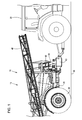
- FIG. 1 illustrates a trailed agricultural implement 10.
- the illustrated trailed agricultural implement 10 is a trailed agricultural sprayer 15.
- Other types of trailed agricultural implements 10 are contemplated by this disclosure.
- the trailed agricultural sprayer 15 is pulled by a vehicle 20.
- the trailed agricultural sprayer 15 includes a frame 25.
- a plurality of wheel assemblies 30 are coupleable to the frame 25 to support the frame 25 above a surface 35.
- a coupling mechanism 40 is coupleable to the frame 25 for coupling the trailed agricultural sprayer 15 to the vehicle 20.
- the trailed agricultural sprayer 15 includes a fluid dispensing apparatus 45.
- the fluid dispensing apparatus 45 is in communication with a hydraulically-driven pump 50.
- the fluid dispensing apparatus 45 is configured to receive a fluid from the hydraulically-driven pump 50 and dispense the fluid.
- the hydraulically-driven pump 50 moves the fluid at an actual fluid rate.
- the illustrated hydraulically-driven pump 50 is a centrifugal pump 55 that may be self-priming.
- Other types of pumps with hydraulic flow rate control are contemplated by this disclosure.
- the hydraulically-driven pump 50 includes a pump pressure input 60.
- the pump pressure input 60 receives a hydraulic fluid 65 from an electro-hydraulic valve 70.
- the hydraulically-driven pump 50 includes a pump return output 75.
- the pump return output 75 returns hydraulic fluid 65 to a vehicle return input 80 of the vehicle 20.
- the hydraulically-driven pump 50 may include a pump case drain 85.
- the pump case drain 85 returns hydraulic fluid 65 to a vehicle drain input 90 of the vehicle 20 at little to no pressure.
- a controller 95 is configured to determine the actual fluid rate.
- the controller 95 communicates with the electro-hydraulic valve 70 to adjust the actual fluid rate to correspond to a desired flow rate.
- the controller 95 may communicate through a wired connection 100 or a wireless connection.
- the electro-hydraulic valve 70 is configured to receive a vehicle hydraulic pressure.
- the electro-hydraulic valve 70 includes a valve pressure input 105 that receives the vehicle hydraulic pressure from a vehicle pressure output 110 of the vehicle 20.
- the electro-hydraulic valve 70 communicates with a vehicle load sense system 115 via a valve sense output 120.
- the electro-hydraulic valve 70 provides hydraulic fluid 65 to the hydraulically-driven pump 50 via a valve motor output 125.
- the electro-hydraulic valve 70 may include a diagnostic receptacle 130.
- the diagnostic receptacle 130 provides a test port for service work.
- the vehicle load sense system 115 includes a vehicle sense input 135.
- the vehicle load sense system 115 senses an implement hydraulic pressure and communicates with a vehicle hydraulic pump.
- the vehicle hydraulic pump adjusts the vehicle hydraulic pressure to correspond to the implement hydraulic pressure. This reduces the possibility that the vehicle will overheat.
- the coupling mechanism 45 of the agricultural implement 10 is coupled to the vehicle 20.
- the agricultural implement 10 is pulled by the vehicle 20 over the surface 35.
- the controller 95 receives the desired fluid rate and determines the actual fluid rate.
- the controller 95 communicates with the electro-hydraulic valve 70 to correspond the actual fluid rate with the desired fluid rate.
- the electro-hydraulic valve 70 receives the vehicle hydraulic pressure.
- the electro-hydraulic valve 70 regulates the vehicle hydraulic pressure to the implement hydraulic pressure that is provided to the hydraulically-driven pump 50. This adjusts the actual fluid rate to correspond to the desired fluid rate.
- the actual fluid rate may change from a minimum flow rate to a maximum flow rate in less than or equal to three seconds.
- the electro-hydraulic valve 70 communicates the implement hydraulic pressure to the vehicle load sense system 115.
- the vehicle load sense system 115 communicates with the vehicle hydraulic pump that adjusts the vehicle hydraulic pressure to correspond to the implement hydraulic pressure. This prevents the vehicle hydraulic pump from pumping more hydraulic fluid than what is needed. This also helps to reduce overheating of the vehicle and to conserve energy.
Landscapes
- Life Sciences & Earth Sciences (AREA)
- Engineering & Computer Science (AREA)
- Insects & Arthropods (AREA)
- Pest Control & Pesticides (AREA)
- Wood Science & Technology (AREA)
- Zoology (AREA)
- Environmental Sciences (AREA)
- Catching Or Destruction (AREA)
- Lifting Devices For Agricultural Implements (AREA)
- Agricultural Machines (AREA)
Abstract
Description
- The present disclosure generally relates to trailed agricultural implements, and more particularly to a pump with hydraulic flow rate control for trailed agricultural implements.
- In order to spray a fluid (e.g., fertilizer, pesticide, fungicide, insecticide) onto agricultural crops, agricultural sprayers commonly include a PTO-driven diaphragm pump. A fluid regulation valve is commonly used to control fluid flow.
- In one embodiment, a trailed agricultural sprayer is disclosed. The trailed agricultural sprayer includes a hydraulically-driven pump for moving a fluid at an actual fluid rate. The hydraulically-driven pump regulates the actual fluid rate. An electro-hydraulic valve is configured to regulate an implement hydraulic pressure to the hydraulically-driven pump. The electro-hydraulic valve is configured to receive a vehicle hydraulic pressure. The electro-hydraulic valve communicates with a vehicle load sense system. The load sense system senses the implement hydraulic pressure and communicates with a vehicle hydraulic pump. The vehicle hydraulic pump adjusts the vehicle hydraulic pressure to correspond to the implement hydraulic pressure. Additional details for the load sense system are defined in ISO 17567, which is hereby incorporated by reference.
- In another embodiment, a trailed agricultural implement is disclosed. The trailed agricultural implement includes a hydraulically-driven pump for moving a fluid at an actual fluid rate. The hydraulically-driven pump regulates the actual fluid rate. An electro-hydraulic valve is configured to regulate an implement hydraulic pressure to the hydraulically-driven pump. The electro-hydraulic valve is configured to receive a vehicle hydraulic pressure. The electro-hydraulic valve communicates with a vehicle load sense system. The load sense system senses the implement hydraulic pressure and communicates with a vehicle hydraulic pump. The vehicle hydraulic pump adjusts the vehicle hydraulic pressure to correspond to the implement hydraulic pressure.
- In yet another embodiment, a method for operating a hydraulically-driven pump to move a fluid on a trailed agricultural implement is disclosed. The method includes receiving a desired fluid rate. The method includes determining an actual fluid rate. The method includes receiving a vehicle hydraulic pressure. The method includes regulating the vehicle hydraulic pressure to an implement hydraulic pressure provided to the hydraulically-driven pump to adjust the actual fluid rate to correspond to the desired fluid rate. The method includes communicating the implement hydraulic pressure to a vehicle load sense system. The vehicle load sense system communicates with a vehicle hydraulic pump. The vehicle hydraulic pump adjusts the vehicle hydraulic pressure to correspond to the implement hydraulic pressure. Other features and aspects will become apparent by consideration of the detailed description and accompanying drawings.
-
-
FIG. 1 is a perspective view of a trailed agricultural implement according to one embodiment. -
FIG. 2 is a schematic of a portion of the trailed agricultural implement shown inFIG. 1 . - Before any embodiments are explained in detail, it is to be understood that the disclosure is not limited in its application to the details of construction and the arrangement of components set forth in the following description or illustrated in the following drawings. The disclosure is capable of other embodiments and of being practiced or of being carried out in various ways. Further embodiments of the invention may include any combination of features from one or more dependent claims, and such features may be incorporated, collectively or separately, into any independent claim.
-
FIG. 1 illustrates a trailedagricultural implement 10. The illustrated trailedagricultural implement 10 is a trailedagricultural sprayer 15. Other types of trailedagricultural implements 10 are contemplated by this disclosure. The trailedagricultural sprayer 15 is pulled by avehicle 20. - With continued reference to
FIG. 1 , the trailedagricultural sprayer 15 includes aframe 25. A plurality ofwheel assemblies 30 are coupleable to theframe 25 to support theframe 25 above asurface 35. Acoupling mechanism 40 is coupleable to theframe 25 for coupling the trailedagricultural sprayer 15 to thevehicle 20. Exemplarily, the trailedagricultural sprayer 15 includes afluid dispensing apparatus 45. Thefluid dispensing apparatus 45 is in communication with a hydraulically-drivenpump 50. Thefluid dispensing apparatus 45 is configured to receive a fluid from the hydraulically-drivenpump 50 and dispense the fluid. - The hydraulically-driven
pump 50 moves the fluid at an actual fluid rate. The illustrated hydraulically-drivenpump 50 is acentrifugal pump 55 that may be self-priming. Other types of pumps with hydraulic flow rate control are contemplated by this disclosure. - With reference to
FIG. 2 , the hydraulically-drivenpump 50 includes apump pressure input 60. Thepump pressure input 60 receives ahydraulic fluid 65 from an electro-hydraulic valve 70. The hydraulically-drivenpump 50 includes apump return output 75. Thepump return output 75 returnshydraulic fluid 65 to avehicle return input 80 of thevehicle 20. The hydraulically-drivenpump 50 may include apump case drain 85. Thepump case drain 85 returnshydraulic fluid 65 to avehicle drain input 90 of thevehicle 20 at little to no pressure. - A
controller 95 is configured to determine the actual fluid rate. Thecontroller 95 communicates with the electro-hydraulic valve 70 to adjust the actual fluid rate to correspond to a desired flow rate. Thecontroller 95 may communicate through awired connection 100 or a wireless connection. - The electro-
hydraulic valve 70 is configured to receive a vehicle hydraulic pressure. The electro-hydraulic valve 70 includes avalve pressure input 105 that receives the vehicle hydraulic pressure from avehicle pressure output 110 of thevehicle 20. The electro-hydraulic valve 70 communicates with a vehicleload sense system 115 via avalve sense output 120. The electro-hydraulic valve 70 provideshydraulic fluid 65 to the hydraulically-drivenpump 50 via avalve motor output 125. Exemplarily, the electro-hydraulic valve 70 may include adiagnostic receptacle 130. Thediagnostic receptacle 130 provides a test port for service work. - The vehicle
load sense system 115 includes avehicle sense input 135. The vehicleload sense system 115 senses an implement hydraulic pressure and communicates with a vehicle hydraulic pump. The vehicle hydraulic pump adjusts the vehicle hydraulic pressure to correspond to the implement hydraulic pressure. This reduces the possibility that the vehicle will overheat. - In operation, the
coupling mechanism 45 of the agricultural implement 10 is coupled to thevehicle 20. The agricultural implement 10 is pulled by thevehicle 20 over thesurface 35. Thecontroller 95 receives the desired fluid rate and determines the actual fluid rate. Thecontroller 95 communicates with the electro-hydraulic valve 70 to correspond the actual fluid rate with the desired fluid rate. The electro-hydraulic valve 70 receives the vehicle hydraulic pressure. The electro-hydraulic valve 70 regulates the vehicle hydraulic pressure to the implement hydraulic pressure that is provided to the hydraulically-drivenpump 50. This adjusts the actual fluid rate to correspond to the desired fluid rate. In the illustrated embodiment, the actual fluid rate may change from a minimum flow rate to a maximum flow rate in less than or equal to three seconds. The electro-hydraulic valve 70 communicates the implement hydraulic pressure to the vehicleload sense system 115. The vehicleload sense system 115 communicates with the vehicle hydraulic pump that adjusts the vehicle hydraulic pressure to correspond to the implement hydraulic pressure. This prevents the vehicle hydraulic pump from pumping more hydraulic fluid than what is needed. This also helps to reduce overheating of the vehicle and to conserve energy. Various features are set forth in the following claims.
Claims (15)
- A trailed agricultural sprayer comprising:a hydraulically-driven pump for moving a fluid at an actual fluid rate; andan electro-hydraulic valve configured to regulate an implement hydraulic pressure to the hydraulically-driven pump that regulates the actual fluid rate;wherein the electro-hydraulic valve is configured to receive a vehicle hydraulic pressure and communicate with a vehicle load sense system that senses the implement hydraulic pressure and communicates with a vehicle hydraulic pump that adjusts the vehicle hydraulic pressure to correspond to the implement hydraulic pressure.
- The trailed agricultural sprayer of claim 1, further comprising a controller configured to determine the actual fluid rate and communicate with the electro-hydraulic valve to adjust the actual fluid rate to correspond to a desired flow rate.
- The trailed agricultural sprayer of claim 1, further comprising a frame configured to support the hydraulically-driven pump.
- The trailed agricultural sprayer of claim 3, further comprising a coupling mechanism coupleable to the frame, the coupling mechanism for coupling to a vehicle.
- The trailed agricultural sprayer of claim 3, further comprising a plurality of wheel assemblies coupleable to the frame, the wheel assemblies supporting the frame above a surface.
- The trailed agricultural sprayer of claim 1, further comprising a fluid dispensing apparatus in communication with the hydraulically-driven pump and configured to dispense the fluid.
- The trailed agricultural sprayer of claim 1, wherein the hydraulically-driven pump is a centrifugal pump.
- The trailed agricultural sprayer of claim 1, wherein the hydraulically-driven pump is a self-priming pump.
- A trailed agricultural implement comprising:a hydraulically-driven pump for moving a fluid at an actual fluid rate; andan electro-hydraulic valve configured to regulate an implement hydraulic pressure to the hydraulically-driven pump that regulates the actual fluid rate;wherein the electro-hydraulic valve is configured to receive a vehicle hydraulic pressure and communicate with a vehicle load sense system that senses the implement hydraulic pressure and communicates with a vehicle hydraulic pump that adjusts the vehicle hydraulic pressure to correspond to the implement hydraulic pressure.
- The trailed agricultural implement of claim 9, further comprising a controller configured to determine the actual fluid rate and communicate with the electro-hydraulic valve to adjust the actual fluid rate to correspond to a desired flow rate.
- The trailed agricultural implement of claim 9, further comprising a frame configured to support the hydraulically-driven pump.
- The trailed agricultural implement of claim 11, further comprising a coupling mechanism coupleable to the frame, the coupling mechanism for coupling to a vehicle.
- The trailed agricultural implement of claim 11, further comprising a plurality of wheel assemblies coupleable to the frame, the wheel assemblies supporting the frame above a surface.
- The trailed agricultural implement of claim 9, wherein the hydraulically-driven pump is a centrifugal pump.
- The trailed agricultural implement of claim 9, wherein the hydraulically-driven pump is a self-priming pump.
Applications Claiming Priority (1)
| Application Number | Priority Date | Filing Date | Title |
|---|---|---|---|
| US13/630,478 US9131674B2 (en) | 2012-09-28 | 2012-09-28 | Trailed agricultural implement pump with hydraulic flow rate control |
Publications (2)
| Publication Number | Publication Date |
|---|---|
| EP2712502A1 true EP2712502A1 (en) | 2014-04-02 |
| EP2712502B1 EP2712502B1 (en) | 2019-05-01 |
Family
ID=49274405
Family Applications (1)
| Application Number | Title | Priority Date | Filing Date |
|---|---|---|---|
| EP13185261.8A Active EP2712502B1 (en) | 2012-09-28 | 2013-09-20 | Trailed agricultural implement pump with hydraulic flow rate control |
Country Status (8)
| Country | Link |
|---|---|
| US (1) | US9131674B2 (en) |
| EP (1) | EP2712502B1 (en) |
| CN (1) | CN103711738A (en) |
| AU (1) | AU2013231086B2 (en) |
| BR (1) | BR102013024755A2 (en) |
| CA (1) | CA2827197C (en) |
| IN (1) | IN2013MU03048A (en) |
| RU (1) | RU2013142082A (en) |
Cited By (1)
| Publication number | Priority date | Publication date | Assignee | Title |
|---|---|---|---|---|
| EP3311035B1 (en) | 2015-06-18 | 2020-07-22 | Väderstad Holding AB | Agricultural implement and method of supplying hydraulic power to an agricultural implement |
Families Citing this family (7)
| Publication number | Priority date | Publication date | Assignee | Title |
|---|---|---|---|---|
| US9781915B2 (en) | 2013-03-14 | 2017-10-10 | Agjunction Llc | Implement and boom height control system and method |
| US9945957B2 (en) * | 2013-03-14 | 2018-04-17 | Agjunction Llc | Machine control system and method |
| EP4219457A1 (en) | 2015-01-26 | 2023-08-02 | Ottawa Hospital Research Institute | 3-(2h)-pyridazinone derivatives, their compositions and methods for viral sensitization |
| US9829014B2 (en) | 2015-04-27 | 2017-11-28 | Caterpillar Inc. | Hydraulic system including independent metering valve with flowsharing |
| BR102018004570B1 (en) * | 2018-03-07 | 2023-01-31 | Nivaldo Mundin Junior | HYDRAULIC ASSEMBLY APPLIED IN AGRICULTURAL SPRAYERS |
| US10601188B2 (en) * | 2018-08-01 | 2020-03-24 | Cnh Industrial America Llc | Jumper harness with LED |
| US20250151710A1 (en) * | 2023-11-09 | 2025-05-15 | Cnh Industrial America Llc | Systems and methods for an agricultural applicator |
Citations (4)
| Publication number | Priority date | Publication date | Assignee | Title |
|---|---|---|---|---|
| US2933897A (en) * | 1957-05-21 | 1960-04-26 | Dravo Corp | Rotary hydraulic booster |
| US4373669A (en) * | 1980-11-28 | 1983-02-15 | International Harvester Co. | Hydraulic drive for an agricultural sprayer |
| US4712376A (en) * | 1986-10-22 | 1987-12-15 | Caterpillar Inc. | Proportional valve control apparatus for fluid systems |
| EP2153710A2 (en) * | 2008-08-11 | 2010-02-17 | Deere & Company | Agricultural sprayer and method for operating the same |
Family Cites Families (7)
| Publication number | Priority date | Publication date | Assignee | Title |
|---|---|---|---|---|
| GB605407A (en) | 1945-12-21 | 1948-07-22 | Leonard Charles Pearch | Improvements in machines for spraying insecticides and the like |
| GB723729A (en) | 1952-11-28 | 1955-02-09 | Weekes & Son Ltd W | Improvements in machines for spraying insecticides and the like |
| GB821564A (en) | 1956-10-23 | 1959-10-07 | Carmichael And Sons Worcester | Improvements relating to apparatus for bi-fluid or multi-fluid spraying |
| US3845777A (en) | 1973-05-25 | 1974-11-05 | P Gilson | Bistable flow control valve |
| CA2088221C (en) | 1993-01-27 | 1996-12-03 | Dennis Tofin | Irrigation apparatus |
| US7415822B1 (en) | 2005-07-21 | 2008-08-26 | Deere & Company | Load sense boost device |
| US7954513B2 (en) * | 2008-03-18 | 2011-06-07 | Deere & Company | Spray application rate regulating valve |
-
2012
- 2012-09-28 US US13/630,478 patent/US9131674B2/en active Active
-
2013
- 2013-09-13 CA CA2827197A patent/CA2827197C/en active Active
- 2013-09-13 RU RU2013142082/13A patent/RU2013142082A/en not_active Application Discontinuation
- 2013-09-19 AU AU2013231086A patent/AU2013231086B2/en active Active
- 2013-09-20 EP EP13185261.8A patent/EP2712502B1/en active Active
- 2013-09-23 IN IN3048MU2013 patent/IN2013MU03048A/en unknown
- 2013-09-26 BR BRBR102013024755-3A patent/BR102013024755A2/en not_active Application Discontinuation
- 2013-09-27 CN CN201310451230.5A patent/CN103711738A/en active Pending
Patent Citations (4)
| Publication number | Priority date | Publication date | Assignee | Title |
|---|---|---|---|---|
| US2933897A (en) * | 1957-05-21 | 1960-04-26 | Dravo Corp | Rotary hydraulic booster |
| US4373669A (en) * | 1980-11-28 | 1983-02-15 | International Harvester Co. | Hydraulic drive for an agricultural sprayer |
| US4712376A (en) * | 1986-10-22 | 1987-12-15 | Caterpillar Inc. | Proportional valve control apparatus for fluid systems |
| EP2153710A2 (en) * | 2008-08-11 | 2010-02-17 | Deere & Company | Agricultural sprayer and method for operating the same |
Non-Patent Citations (1)
| Title |
|---|
| "AGRICULTURAL AND FORESTRY TRACTORS AND IMPLEMENTS- HYDRAULIC POWER BEYOND", INTERNATIONAL STANDARD ISO17567, 1 May 2005 (2005-05-01), pages 1PP, II-IV, 1 - 9, 3PP, XP003035370 |
Cited By (1)
| Publication number | Priority date | Publication date | Assignee | Title |
|---|---|---|---|---|
| EP3311035B1 (en) | 2015-06-18 | 2020-07-22 | Väderstad Holding AB | Agricultural implement and method of supplying hydraulic power to an agricultural implement |
Also Published As
| Publication number | Publication date |
|---|---|
| RU2013142082A (en) | 2015-03-20 |
| CA2827197A1 (en) | 2014-03-28 |
| US9131674B2 (en) | 2015-09-15 |
| CN103711738A (en) | 2014-04-09 |
| BR102013024755A2 (en) | 2015-08-11 |
| AU2013231086A1 (en) | 2014-04-17 |
| AU2013231086B2 (en) | 2017-03-23 |
| EP2712502B1 (en) | 2019-05-01 |
| US20140093397A1 (en) | 2014-04-03 |
| IN2013MU03048A (en) | 2015-07-31 |
| CA2827197C (en) | 2021-05-18 |
Similar Documents
| Publication | Publication Date | Title |
|---|---|---|
| US9131674B2 (en) | Trailed agricultural implement pump with hydraulic flow rate control | |
| US11932231B2 (en) | System and method for purging agricultural sprayer nozzles based on air pressure | |
| US11439139B2 (en) | Agricultural sprayer control system and method | |
| RU2610751C2 (en) | Hydraulic system for self-propelled working agricultural machine and method of radiator fan operating with hydrostatic drive mounted in such machine | |
| EP3763209B1 (en) | Agricultural vehicle | |
| US20110146258A1 (en) | Hydraulic Circuit | |
| EP2886877B1 (en) | Power beyond valve assembly for an agricultural implement | |
| WO2011069494A3 (en) | Continuously conveying infusion pump | |
| US20220202002A1 (en) | Agricultural sprayer control system | |
| US6883726B2 (en) | Fluid sprayer system using modulated control valve and a positive displacement pump | |
| KR200485967Y1 (en) | Double type sprayer sprayed to left and right | |
| KR20200078273A (en) | Pesticide spraying device installed on tractor | |
| KR200304127Y1 (en) | Agricultural Medicines spade for Irrigation Apparatus | |
| US20250212865A1 (en) | Method for Distributing Spray onto an Agricultural Area, and Agricultural Spray Device | |
| AU2022200217A1 (en) | System and method for dispensing agricultural fluids onto plants present within a field based on plant size | |
| US4373669A (en) | Hydraulic drive for an agricultural sprayer | |
| EP3975715B1 (en) | Agricultural sprayer control system | |
| RU2489836C2 (en) | Agricultural machine and device, and method for supplying liquid to dispenser | |
| KR20170081545A (en) | Double type sprayer sprayed to left and right | |
| KR20240012696A (en) | pest control | |
| KR101406007B1 (en) | Individual pressure regulating apparatus of spray | |
| US20240301899A1 (en) | System and Method for Controlling a Mobile Agricultural Machine Having a Hydraulic Supply System | |
| RU2024108488A (en) | SYSTEMS, METHODS AND DEVICE FOR CONTROL OF LIQUID FERTILIZER FOR AGRICULTURAL IMPLEMENTS | |
| WO2012030889A1 (en) | Hydraulic system for agricultural tractors, and agricultural tractor | |
| JP3180583U (en) | Power sprayer |
Legal Events
| Date | Code | Title | Description |
|---|---|---|---|
| PUAI | Public reference made under article 153(3) epc to a published international application that has entered the european phase |
Free format text: ORIGINAL CODE: 0009012 |
|
| AK | Designated contracting states |
Kind code of ref document: A1 Designated state(s): AL AT BE BG CH CY CZ DE DK EE ES FI FR GB GR HR HU IE IS IT LI LT LU LV MC MK MT NL NO PL PT RO RS SE SI SK SM TR |
|
| AX | Request for extension of the european patent |
Extension state: BA ME |
|
| 17P | Request for examination filed |
Effective date: 20141002 |
|
| RBV | Designated contracting states (corrected) |
Designated state(s): AL AT BE BG CH CY CZ DE DK EE ES FI FR GB GR HR HU IE IS IT LI LT LU LV MC MK MT NL NO PL PT RO RS SE SI SK SM TR |
|
| TPAC | Observations filed by third parties |
Free format text: ORIGINAL CODE: EPIDOSNTIPA |
|
| STAA | Information on the status of an ep patent application or granted ep patent |
Free format text: STATUS: EXAMINATION IS IN PROGRESS |
|
| 17Q | First examination report despatched |
Effective date: 20170803 |
|
| GRAP | Despatch of communication of intention to grant a patent |
Free format text: ORIGINAL CODE: EPIDOSNIGR1 |
|
| STAA | Information on the status of an ep patent application or granted ep patent |
Free format text: STATUS: GRANT OF PATENT IS INTENDED |
|
| INTG | Intention to grant announced |
Effective date: 20181127 |
|
| GRAS | Grant fee paid |
Free format text: ORIGINAL CODE: EPIDOSNIGR3 |
|
| GRAA | (expected) grant |
Free format text: ORIGINAL CODE: 0009210 |
|
| STAA | Information on the status of an ep patent application or granted ep patent |
Free format text: STATUS: THE PATENT HAS BEEN GRANTED |
|
| AK | Designated contracting states |
Kind code of ref document: B1 Designated state(s): AL AT BE BG CH CY CZ DE DK EE ES FI FR GB GR HR HU IE IS IT LI LT LU LV MC MK MT NL NO PL PT RO RS SE SI SK SM TR |
|
| REG | Reference to a national code |
Ref country code: GB Ref legal event code: FG4D |
|
| REG | Reference to a national code |
Ref country code: CH Ref legal event code: EP Ref country code: AT Ref legal event code: REF Ref document number: 1125690 Country of ref document: AT Kind code of ref document: T Effective date: 20190515 |
|
| REG | Reference to a national code |
Ref country code: DE Ref legal event code: R096 Ref document number: 602013054553 Country of ref document: DE |
|
| REG | Reference to a national code |
Ref country code: IE Ref legal event code: FG4D |
|
| REG | Reference to a national code |
Ref country code: NL Ref legal event code: FP |
|
| REG | Reference to a national code |
Ref country code: LT Ref legal event code: MG4D |
|
| PG25 | Lapsed in a contracting state [announced via postgrant information from national office to epo] |
Ref country code: FI Free format text: LAPSE BECAUSE OF FAILURE TO SUBMIT A TRANSLATION OF THE DESCRIPTION OR TO PAY THE FEE WITHIN THE PRESCRIBED TIME-LIMIT Effective date: 20190501 Ref country code: SE Free format text: LAPSE BECAUSE OF FAILURE TO SUBMIT A TRANSLATION OF THE DESCRIPTION OR TO PAY THE FEE WITHIN THE PRESCRIBED TIME-LIMIT Effective date: 20190501 Ref country code: LT Free format text: LAPSE BECAUSE OF FAILURE TO SUBMIT A TRANSLATION OF THE DESCRIPTION OR TO PAY THE FEE WITHIN THE PRESCRIBED TIME-LIMIT Effective date: 20190501 Ref country code: ES Free format text: LAPSE BECAUSE OF FAILURE TO SUBMIT A TRANSLATION OF THE DESCRIPTION OR TO PAY THE FEE WITHIN THE PRESCRIBED TIME-LIMIT Effective date: 20190501 Ref country code: AL Free format text: LAPSE BECAUSE OF FAILURE TO SUBMIT A TRANSLATION OF THE DESCRIPTION OR TO PAY THE FEE WITHIN THE PRESCRIBED TIME-LIMIT Effective date: 20190501 Ref country code: PT Free format text: LAPSE BECAUSE OF FAILURE TO SUBMIT A TRANSLATION OF THE DESCRIPTION OR TO PAY THE FEE WITHIN THE PRESCRIBED TIME-LIMIT Effective date: 20190901 Ref country code: NO Free format text: LAPSE BECAUSE OF FAILURE TO SUBMIT A TRANSLATION OF THE DESCRIPTION OR TO PAY THE FEE WITHIN THE PRESCRIBED TIME-LIMIT Effective date: 20190801 Ref country code: HR Free format text: LAPSE BECAUSE OF FAILURE TO SUBMIT A TRANSLATION OF THE DESCRIPTION OR TO PAY THE FEE WITHIN THE PRESCRIBED TIME-LIMIT Effective date: 20190501 |
|
| PG25 | Lapsed in a contracting state [announced via postgrant information from national office to epo] |
Ref country code: LV Free format text: LAPSE BECAUSE OF FAILURE TO SUBMIT A TRANSLATION OF THE DESCRIPTION OR TO PAY THE FEE WITHIN THE PRESCRIBED TIME-LIMIT Effective date: 20190501 Ref country code: BG Free format text: LAPSE BECAUSE OF FAILURE TO SUBMIT A TRANSLATION OF THE DESCRIPTION OR TO PAY THE FEE WITHIN THE PRESCRIBED TIME-LIMIT Effective date: 20190801 Ref country code: GR Free format text: LAPSE BECAUSE OF FAILURE TO SUBMIT A TRANSLATION OF THE DESCRIPTION OR TO PAY THE FEE WITHIN THE PRESCRIBED TIME-LIMIT Effective date: 20190802 Ref country code: RS Free format text: LAPSE BECAUSE OF FAILURE TO SUBMIT A TRANSLATION OF THE DESCRIPTION OR TO PAY THE FEE WITHIN THE PRESCRIBED TIME-LIMIT Effective date: 20190501 |
|
| REG | Reference to a national code |
Ref country code: AT Ref legal event code: MK05 Ref document number: 1125690 Country of ref document: AT Kind code of ref document: T Effective date: 20190501 |
|
| PG25 | Lapsed in a contracting state [announced via postgrant information from national office to epo] |
Ref country code: IS Free format text: LAPSE BECAUSE OF FAILURE TO SUBMIT A TRANSLATION OF THE DESCRIPTION OR TO PAY THE FEE WITHIN THE PRESCRIBED TIME-LIMIT Effective date: 20190901 |
|
| PG25 | Lapsed in a contracting state [announced via postgrant information from national office to epo] |
Ref country code: CZ Free format text: LAPSE BECAUSE OF FAILURE TO SUBMIT A TRANSLATION OF THE DESCRIPTION OR TO PAY THE FEE WITHIN THE PRESCRIBED TIME-LIMIT Effective date: 20190501 Ref country code: RO Free format text: LAPSE BECAUSE OF FAILURE TO SUBMIT A TRANSLATION OF THE DESCRIPTION OR TO PAY THE FEE WITHIN THE PRESCRIBED TIME-LIMIT Effective date: 20190501 Ref country code: DK Free format text: LAPSE BECAUSE OF FAILURE TO SUBMIT A TRANSLATION OF THE DESCRIPTION OR TO PAY THE FEE WITHIN THE PRESCRIBED TIME-LIMIT Effective date: 20190501 Ref country code: EE Free format text: LAPSE BECAUSE OF FAILURE TO SUBMIT A TRANSLATION OF THE DESCRIPTION OR TO PAY THE FEE WITHIN THE PRESCRIBED TIME-LIMIT Effective date: 20190501 Ref country code: AT Free format text: LAPSE BECAUSE OF FAILURE TO SUBMIT A TRANSLATION OF THE DESCRIPTION OR TO PAY THE FEE WITHIN THE PRESCRIBED TIME-LIMIT Effective date: 20190501 Ref country code: SK Free format text: LAPSE BECAUSE OF FAILURE TO SUBMIT A TRANSLATION OF THE DESCRIPTION OR TO PAY THE FEE WITHIN THE PRESCRIBED TIME-LIMIT Effective date: 20190501 |
|
| REG | Reference to a national code |
Ref country code: DE Ref legal event code: R097 Ref document number: 602013054553 Country of ref document: DE |
|
| PG25 | Lapsed in a contracting state [announced via postgrant information from national office to epo] |
Ref country code: SM Free format text: LAPSE BECAUSE OF FAILURE TO SUBMIT A TRANSLATION OF THE DESCRIPTION OR TO PAY THE FEE WITHIN THE PRESCRIBED TIME-LIMIT Effective date: 20190501 Ref country code: IT Free format text: LAPSE BECAUSE OF FAILURE TO SUBMIT A TRANSLATION OF THE DESCRIPTION OR TO PAY THE FEE WITHIN THE PRESCRIBED TIME-LIMIT Effective date: 20190501 |
|
| PLBE | No opposition filed within time limit |
Free format text: ORIGINAL CODE: 0009261 |
|
| STAA | Information on the status of an ep patent application or granted ep patent |
Free format text: STATUS: NO OPPOSITION FILED WITHIN TIME LIMIT |
|
| PG25 | Lapsed in a contracting state [announced via postgrant information from national office to epo] |
Ref country code: TR Free format text: LAPSE BECAUSE OF FAILURE TO SUBMIT A TRANSLATION OF THE DESCRIPTION OR TO PAY THE FEE WITHIN THE PRESCRIBED TIME-LIMIT Effective date: 20190501 |
|
| 26N | No opposition filed |
Effective date: 20200204 |
|
| PG25 | Lapsed in a contracting state [announced via postgrant information from national office to epo] |
Ref country code: PL Free format text: LAPSE BECAUSE OF FAILURE TO SUBMIT A TRANSLATION OF THE DESCRIPTION OR TO PAY THE FEE WITHIN THE PRESCRIBED TIME-LIMIT Effective date: 20190501 |
|
| PG25 | Lapsed in a contracting state [announced via postgrant information from national office to epo] |
Ref country code: SI Free format text: LAPSE BECAUSE OF FAILURE TO SUBMIT A TRANSLATION OF THE DESCRIPTION OR TO PAY THE FEE WITHIN THE PRESCRIBED TIME-LIMIT Effective date: 20190501 Ref country code: MC Free format text: LAPSE BECAUSE OF FAILURE TO SUBMIT A TRANSLATION OF THE DESCRIPTION OR TO PAY THE FEE WITHIN THE PRESCRIBED TIME-LIMIT Effective date: 20190501 |
|
| REG | Reference to a national code |
Ref country code: CH Ref legal event code: PL |
|
| PG25 | Lapsed in a contracting state [announced via postgrant information from national office to epo] |
Ref country code: CH Free format text: LAPSE BECAUSE OF NON-PAYMENT OF DUE FEES Effective date: 20190930 Ref country code: LI Free format text: LAPSE BECAUSE OF NON-PAYMENT OF DUE FEES Effective date: 20190930 Ref country code: LU Free format text: LAPSE BECAUSE OF NON-PAYMENT OF DUE FEES Effective date: 20190920 Ref country code: IE Free format text: LAPSE BECAUSE OF NON-PAYMENT OF DUE FEES Effective date: 20190920 |
|
| REG | Reference to a national code |
Ref country code: BE Ref legal event code: MM Effective date: 20190930 |
|
| PG25 | Lapsed in a contracting state [announced via postgrant information from national office to epo] |
Ref country code: BE Free format text: LAPSE BECAUSE OF NON-PAYMENT OF DUE FEES Effective date: 20190930 |
|
| PG25 | Lapsed in a contracting state [announced via postgrant information from national office to epo] |
Ref country code: CY Free format text: LAPSE BECAUSE OF FAILURE TO SUBMIT A TRANSLATION OF THE DESCRIPTION OR TO PAY THE FEE WITHIN THE PRESCRIBED TIME-LIMIT Effective date: 20190501 |
|
| PG25 | Lapsed in a contracting state [announced via postgrant information from national office to epo] |
Ref country code: HU Free format text: LAPSE BECAUSE OF FAILURE TO SUBMIT A TRANSLATION OF THE DESCRIPTION OR TO PAY THE FEE WITHIN THE PRESCRIBED TIME-LIMIT; INVALID AB INITIO Effective date: 20130920 Ref country code: MT Free format text: LAPSE BECAUSE OF FAILURE TO SUBMIT A TRANSLATION OF THE DESCRIPTION OR TO PAY THE FEE WITHIN THE PRESCRIBED TIME-LIMIT Effective date: 20190501 |
|
| PG25 | Lapsed in a contracting state [announced via postgrant information from national office to epo] |
Ref country code: MK Free format text: LAPSE BECAUSE OF FAILURE TO SUBMIT A TRANSLATION OF THE DESCRIPTION OR TO PAY THE FEE WITHIN THE PRESCRIBED TIME-LIMIT Effective date: 20190501 |
|
| PGFP | Annual fee paid to national office [announced via postgrant information from national office to epo] |
Ref country code: DE Payment date: 20250820 Year of fee payment: 13 |
|
| PGFP | Annual fee paid to national office [announced via postgrant information from national office to epo] |
Ref country code: NL Payment date: 20250926 Year of fee payment: 13 |
|
| PGFP | Annual fee paid to national office [announced via postgrant information from national office to epo] |
Ref country code: GB Payment date: 20250929 Year of fee payment: 13 |
|
| PGFP | Annual fee paid to national office [announced via postgrant information from national office to epo] |
Ref country code: FR Payment date: 20250925 Year of fee payment: 13 |