EP2712067A1 - Small power generating device and mobile electronic device - Google Patents
Small power generating device and mobile electronic device Download PDFInfo
- Publication number
- EP2712067A1 EP2712067A1 EP12785758.9A EP12785758A EP2712067A1 EP 2712067 A1 EP2712067 A1 EP 2712067A1 EP 12785758 A EP12785758 A EP 12785758A EP 2712067 A1 EP2712067 A1 EP 2712067A1
- Authority
- EP
- European Patent Office
- Prior art keywords
- power generator
- disposed
- small power
- shaft
- rotary dial
- Prior art date
- Legal status (The legal status is an assumption and is not a legal conclusion. Google has not performed a legal analysis and makes no representation as to the accuracy of the status listed.)
- Granted
Links
Images





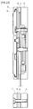
Classifications
-
- H—ELECTRICITY
- H02—GENERATION; CONVERSION OR DISTRIBUTION OF ELECTRIC POWER
- H02K—DYNAMO-ELECTRIC MACHINES
- H02K7/00—Arrangements for handling mechanical energy structurally associated with dynamo-electric machines, e.g. structural association with mechanical driving motors or auxiliary dynamo-electric machines
- H02K7/10—Structural association with clutches, brakes, gears, pulleys or mechanical starters
- H02K7/116—Structural association with clutches, brakes, gears, pulleys or mechanical starters with gears
-
- H—ELECTRICITY
- H02—GENERATION; CONVERSION OR DISTRIBUTION OF ELECTRIC POWER
- H02K—DYNAMO-ELECTRIC MACHINES
- H02K7/00—Arrangements for handling mechanical energy structurally associated with dynamo-electric machines, e.g. structural association with mechanical driving motors or auxiliary dynamo-electric machines
- H02K7/18—Structural association of electric generators with mechanical driving motors, e.g. with turbines
-
- H—ELECTRICITY
- H02—GENERATION; CONVERSION OR DISTRIBUTION OF ELECTRIC POWER
- H02J—ELECTRIC POWER NETWORKS; CIRCUIT ARRANGEMENTS OR SYSTEMS FOR SUPPLYING OR DISTRIBUTING ELECTRIC POWER; SYSTEMS FOR STORING ELECTRIC ENERGY
- H02J7/00—Circuit arrangements for charging or discharging batteries or for supplying loads from batteries
-
- H—ELECTRICITY
- H02—GENERATION; CONVERSION OR DISTRIBUTION OF ELECTRIC POWER
- H02K—DYNAMO-ELECTRIC MACHINES
- H02K7/00—Arrangements for handling mechanical energy structurally associated with dynamo-electric machines, e.g. structural association with mechanical driving motors or auxiliary dynamo-electric machines
- H02K7/18—Structural association of electric generators with mechanical driving motors, e.g. with turbines
- H02K7/1807—Rotary generators
- H02K7/1861—Rotary generators driven by animals or vehicles
-
- H—ELECTRICITY
- H01—ELECTRIC ELEMENTS
- H01M—PROCESSES OR MEANS, e.g. BATTERIES, FOR THE DIRECT CONVERSION OF CHEMICAL ENERGY INTO ELECTRICAL ENERGY
- H01M10/00—Secondary cells; Manufacture thereof
- H01M10/42—Methods or arrangements for servicing or maintenance of secondary cells or secondary half-cells
- H01M10/44—Methods for charging or discharging
-
- H—ELECTRICITY
- H01—ELECTRIC ELEMENTS
- H01M—PROCESSES OR MEANS, e.g. BATTERIES, FOR THE DIRECT CONVERSION OF CHEMICAL ENERGY INTO ELECTRICAL ENERGY
- H01M10/00—Secondary cells; Manufacture thereof
- H01M10/42—Methods or arrangements for servicing or maintenance of secondary cells or secondary half-cells
- H01M10/46—Accumulators structurally combined with charging apparatus
-
- H—ELECTRICITY
- H02—GENERATION; CONVERSION OR DISTRIBUTION OF ELECTRIC POWER
- H02J—ELECTRIC POWER NETWORKS; CIRCUIT ARRANGEMENTS OR SYSTEMS FOR SUPPLYING OR DISTRIBUTING ELECTRIC POWER; SYSTEMS FOR STORING ELECTRIC ENERGY
- H02J7/00—Circuit arrangements for charging or discharging batteries or for supplying loads from batteries
- H02J7/32—Circuit arrangements for charging or discharging batteries or for supplying loads from batteries for charging batteries from a charging set comprising a non-electric prime mover rotating at constant speed
-
- H—ELECTRICITY
- H04—ELECTRIC COMMUNICATION TECHNIQUE
- H04M—TELEPHONIC COMMUNICATION
- H04M19/00—Current supply arrangements for telephone systems
- H04M19/08—Current supply arrangements for telephone systems with current supply sources at the substations
-
- Y—GENERAL TAGGING OF NEW TECHNOLOGICAL DEVELOPMENTS; GENERAL TAGGING OF CROSS-SECTIONAL TECHNOLOGIES SPANNING OVER SEVERAL SECTIONS OF THE IPC; TECHNICAL SUBJECTS COVERED BY FORMER USPC CROSS-REFERENCE ART COLLECTIONS [XRACs] AND DIGESTS
- Y02—TECHNOLOGIES OR APPLICATIONS FOR MITIGATION OR ADAPTATION AGAINST CLIMATE CHANGE
- Y02B—CLIMATE CHANGE MITIGATION TECHNOLOGIES RELATED TO BUILDINGS, e.g. HOUSING, HOUSE APPLIANCES OR RELATED END-USER APPLICATIONS
- Y02B40/00—Technologies aiming at improving the efficiency of home appliances, e.g. induction cooking or efficient technologies for refrigerators, freezers or dish washers
-
- Y—GENERAL TAGGING OF NEW TECHNOLOGICAL DEVELOPMENTS; GENERAL TAGGING OF CROSS-SECTIONAL TECHNOLOGIES SPANNING OVER SEVERAL SECTIONS OF THE IPC; TECHNICAL SUBJECTS COVERED BY FORMER USPC CROSS-REFERENCE ART COLLECTIONS [XRACs] AND DIGESTS
- Y02—TECHNOLOGIES OR APPLICATIONS FOR MITIGATION OR ADAPTATION AGAINST CLIMATE CHANGE
- Y02E—REDUCTION OF GREENHOUSE GAS [GHG] EMISSIONS, RELATED TO ENERGY GENERATION, TRANSMISSION OR DISTRIBUTION
- Y02E60/00—Enabling technologies; Technologies with a potential or indirect contribution to GHG emissions mitigation
- Y02E60/10—Energy storage using batteries
Definitions
- the present invention relates to a small power generator and a portable electronic apparatus, for example, relates to a small power generator that generates electric power by manual rotation.
- Various portable electronic apparatuses such as wireless communication apparatuses including a mobile phone to make calls or e-mails using a wireless communication function or reproduction apparatuses that reproduce the stored music data or display the character information, are widely used. All of these portable electronic apparatuses include a battery, and wireless communication or reproduction processing is performed by the electric power from the battery.
- the portable electronic apparatus is used in a state where the battery is charged by being connected to the household power supply or used in a state where a small battery as a spare external power supply is connected thereto. In any case, however, there is a problem in that communication is not possible when power consumption at the outside increases and the electric power of a predetermined level or more has been used.
- a mobile phone including a small power generator (PTL 1) or a portable hand generator connectable to a mobile phone and the like (PTL 2) has been proposed.
- At least one rotary shaft of the intermediate gear for transmitting the rotation of the driving gear to the driven gear is disposed outside the rotor within the stator. Therefore, it is possible to provide a small power generator having a sufficient power generation capacity to use a predetermined function.
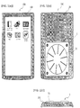
- Fig. 1 is a diagram showing the configuration of the appearance of a mobile phone (portable electronic apparatus) 100 in which a small power generator 1 is mounted.
- the small power generator 1 is mainly disposed on the back surface of a housing 101.
- a rotary dial 31 is disposed in the middle of the surface, and the rotary dial 31 can be turned by hands or fingers put on a plurality of rotary dial protrusions 33 radially formed on the surface.
- a rotor of an inner rotor type power generation unit 6, which is disposed inside the small power generator 1, is rotated by the rotational force through at least one intermediate gear.
- electric power is generated to charge the power supply for the portable electronic apparatus 100 or charge the spare power supply (for example, a secondary battery or a large-capacity capacitor).
- the small power generator 1 can generate electric power to the extent that the standby state (monitoring of incoming calls or e-mails and incoming call processing when there is an incoming call) can be maintained for 10 minutes in the case of a mobile phone although this depends on the ratio of the gear for transmitting rotational power or the size of the small power generator 1. That is, by the rotation of the rotary dial 31, a permanent magnet 65 of the rotor portion is rotated at 3000 rpm to 7000 rpm. By this rotational speed, it is possible to supply a voltage of 3 V to 5 V and a sufficient current for charging.
- the small power generator 1 of the present embodiment is formed in the size of 3 square centimeters to 5 square centimeters and 6 mm to 10 mm in thickness, and accordingly miniaturization and small thickness are realized.
- the small power generator 1 includes an intermediate gear in order to transmit the rotational force of the rotary dial 31 to a rotating unit 3, and at least one of the shafts of the intermediate gear is provided between a plurality of core windings 67 circularly disposed in a stator core 66 of the power generation unit 6.
- the planar size is reduced by providing the shaft of the intermediate gear inside the stator core of the inner rotor type power generator.
- both the shafts can be supported by a common receiving plate 42. Therefore, it is possible to reduce the overall thickness.
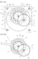
- Fig. 2 is a cross-sectional view taken along each axis of the small power generator 1 in a first embodiment.
- a corresponding location in Fig. 2 is painted in black.
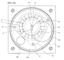
- Fig. 4 shows a state (a) when a small power generator is viewed from the front and a state (b) where a rotating unit is removed.
- the small power generator 1 is configured to include a housing unit 2, the rotating unit 3, the receiving unit 4, the transmission unit 5, and the power generation unit 6.
- the small power generator 1 is formed in a rectangular shape of 3 cm to 5 cm, and four corners are fixed by screws 24.
- FIG. 2 a cross-section along the broken line passing through each axis is shown (diagram on the right side), and a state screwed by the screw 24 is shown in a diagram on the left side.
- the housing unit 2 is a housing in which each of the rotating unit 3 to the power generation unit 6 of the small power generator 1 is housed.
- the housing unit 2 is configured to include a base 21, an intermediate plate 22, a cover 23, and the screw 24 for fixing these.
- the base 21, the intermediate plate 22, and the cover 23 have the same rectangular shape.
- screw holes for fixing with the screw 24 are formed at positions where the central axes are the same.
- a bearing hole for pivotally supporting the rotor shaft 61 passes through a position shifted from the center (intersection of diagonals).
- the dial shaft 32 of the rotary dial 31 is disposed at the center of the base 21, the dial shaft 32 and the rotor shaft 61 are disposed at positions shifted from each other. Therefore, since both the shafts 32 and 61 can be pivotally supported on the same plane using the common receiving plate 42, it is possible to reduce the thickness.
- a first recess 21a which has a circular shape having a radius r1 with a bearing hole for the rotor shaft 61 as the center, is formed in the base 21, and a second recess 21b, which has a radius r2 ( ⁇ r1) with the same bearing hole as the center, is further formed below the first recess 21a.
- a housing portion of the power generation unit 6 is formed by the first and second recesses 21a and 21b.
- a circular base step portion 21c is formed by the bottom surface of the first recess 21a and the peripheral surface of the second recess 21b, and the stator core 66 is placed on the base step portion 21c.
- a bearing hole for pivotally supporting a transmission shaft 51 which is a shaft of the intermediate gear, passes through a position at a predetermined distance in a central direction from the inner peripheral surface.
- a cutout portion 66c by cutting a part of the inside of a circular portion 66a away and dispose the transmission shaft 51 such that a part of the transmission shaft 51 fits into the cutout portion 66c.
- the transmission shaft 51 when the diameter of the transmission shaft 51 is smaller than the width of the circular portion 66a, it is also possible to provide a through hole of the transmission shaft 51 in the circular portion 66a and dispose the transmission shaft 51, which passes through the through hole, in the base 21.
- the transmission shaft 51 is pivotally supported by an oil-retaining bearing 52 disposed in the base step portion 21c of the base 21.
- the transmission shaft 51 may be disposed on the circular portion 66a by providing the oil-retaining bearing 52, which pivotally supports the transmission shaft 51, in the circular portion 66a.
- Three strut holes for a strut 41 are formed in portions of the base 21 excluding the first recess 21a.
- the intermediate plate 22 is disposed on the upper side where the first recess 21a of the base 21 is formed.
- the intermediate plate 22 has a rectangular shape. At the center of the intermediate plate 22, a circular hole having a diameter slightly smaller than the maximum outer diameter of the rotary dial 31 is provided.
- a through recess 22a penetrating to the outside from the inside of the circle diameter hole is provided on a surface of the intermediate plate 22 that is in contact with the base 21, a through recess 22a penetrating to the outside from the inside of the circle diameter hole is provided.
- a through hole penetrating from the inside to the outside is formed on the side surface of the housing unit 2.
- a substrate 69 for extracting the electric power generated by the power generation unit 6 is disposed in the through recess 22a. Therefore, the depth of the through recess 22a is approximately the thickness of the substrate 69.
- the intermediate plate 22 and the base 21 may be integrally formed, and the substrate 69 for extracting the generated electric power to the outside or a through hole, through which wiring lines pass, may be provided on the side surface or the bottom surface.
- a circular recess for the rotary dial 31 is further formed above the first recess 21a. The center of this circular recess is matched with the center of the rotary dial 31.
- the cover 23 is disposed above the base 21.
- the cover 23 has the same rectangular shape as the base 21 and the intermediate plate 22 when the small power generator 1 is produced as an independent product.
- a portable electronic apparatus such as a mobile phone, a smart phone, or a sound data reproduction apparatus
- the cover 23 is formed in a circular shape such that the cross-section has an inverted L shape, and is configured to include a circular portion that forms a pressing portion 23c and a peripheral wall portion erected in the outer periphery.
- a circular recess 23a having a diameter slightly larger than the maximum outer diameter of the rotary dial 31 is formed at the center of the cover 23.
- a circular dial hole 23b having a diameter slightly smaller than the maximum outer diameter of the rotary dial 31 is formed in the middle of the bottom surface of the circular recess 23a.
- the pressing portion 23c for pressing the rotary dial 31 is formed by the remaining bottom portion of the recess 23a.
- the rotating unit 3 is a member that is disposed in the middle of the upper portion of the small power generator 1 and is used when a user performs a rotation operation to generate the electric power.
- the rotary dial protrusion 33 is formed on the upper surface of the rotating unit 3 so that a finger is put on the rotary dial protrusion 33 when the user performs a rotation operation. As shown in Fig. 4(a) , a plurality of (in the present embodiment, 10) rotary dial protrusions 33 are radially provided.
- the strength of the rotary dial 31 can be increased by forming a plurality of rotary dial protrusions 33 radially, it is possible to form the rotary dial 31 to be thin.
- a shaft hole for a sliding bearing is formed at the inside center of the rotating unit 3, and is pivotally supported by the dial shaft 32.
- a circular recess 34 is formed concentrically with the shaft center of the dial shaft 32.
- a driving gear 35 is formed on the inner peripheral wall of the circular recess 34.
- the driving gear 35 is integrally formed on the inner peripheral wall of the circular recess 34 by molding, sintering, and the like. However, the driving gear 35 that is separately formed in a ring shape may be fixed to the inner peripheral wall of the circular recess 34.
- the rotational driving force of the rotary dial 31 is transmitted through the driving gear 35.
- a thin circular engaging portion 36 is formed over the entire periphery.
- the circular engaging portion 36 is covered by the pressing portion 23c of the cover 23 with a predetermined gap interposed therebetween so that the rotary dial 31 does not come off.
- a circular sliding protrusion 37 is formed over the entire periphery, and the sliding protrusion 37 is in contact with the intermediate plate 22.
- a contact portion of the sliding protrusion 37 and the intermediate plate 22 slide when the rotary dial 31 is rotated.
- the center is supported by the receiving plate 42 on the dial shaft 32, and the outer peripheral side of the bottom surface facing the receiving plate 42 is supported by the intermediate plate 22. Therefore, since the strength of the rotary dial 31 can be increased, it is possible to form the rotary dial 31 to be thin.
- the receiving unit 4 is a member that is disposed between the housing unit 2 and the rotating unit 3 and is for pivotally supporting each shaft (the dial shaft 32, the transmission shaft 51, and the rotor shaft 61) of the small power generator 1.
- the receiving unit 4 is configured to include three struts 41, the receiving plate 42, and a screw 43.
- the struts 41 are fixed to three strut holes formed in the base 21 by driving.
- Fig. 4(b) shows a state where the rotary dial 31 is detached from a state shown in Fig. 4(a) when the small power generator 1 is viewed from the top.
- Three struts 41 are provided at positions, which do not overlap the receiving unit 4 and the transmission unit 5, in the base 21 on the inner side of the intermediate plate 22 (refer to the screw 43 attached to the strut 41 in Fig. 4(b) ).
- Three struts 41 are disposed such that the shaft center of the dial shaft 32 is positioned at the approximately central portion of the three points. Accordingly, the three struts 41 can stably receive the force generated during the rotation of the rotary dial 31.
- the strut 41 may be screwed to the base 21 by forming a screw on the outer peripheral surface of the strut 41.
- the receiving plate 42 having an approximately triangular shape whose three sides are curved outward is disposed, and is fixed to the strut 41 by the screw 43.
- a fixing hole 42a for the dial shaft 32, a shaft hole for the rotor shaft 61, and a shaft hole for the transmission shaft 51 are formed at corresponding positions in the receiving plate 42.
- both the shafts can be fixed and pivotally supported on the same receiving plate 42.
- the small power generator 1 can be made thin.
- the dial shaft 32 In the dial shaft 32, the lower side of the bearing portion of the dial shaft 32 is fixed to the fixing hole portion by driving.
- the dial shaft 32 may be fixed by other methods, such as welding and screw fixing.
- the transmission unit 5 is a member for transmitting the rotation of the rotary dial 31 to the rotor shaft 61 of the power generation unit 6.
- the transmission unit 5 is configured to include the transmission shaft 51, the oil-retaining bearing 52, an oil-retaining bearing 53, a second intermediate gear 54, and a first intermediate gear 55.
- One end of the transmission shaft 51 is pivotally supported on the base 21 by the oil-retaining bearing 52, and the other end side is pivotally supported on the receiving plate 42 by the oil-retaining bearing 53.
- the oil-retaining bearing 53 side of the transmission shaft 51 penetrates the receiving plate 42, and the first intermediate gear 55 is fixed to the end by spline or using a key and a groove.
- the first intermediate gear 55 is located in the circular recess 34 of the rotary dial 31, and meshes with the driving gear 35 (refer to Figs. 2 and 4(a) ).
- the second intermediate gear 54 is integrally formed between both the pivotally supported portions of the transmission shaft 51, and the second intermediate gear 54 meshes with a driven gear 62 formed on the rotor shaft 61 (refer to Figs. 2 and 5(a) ).
- the second intermediate gear 54 may be formed separately from the transmission shaft 51 and be attached to the transmission shaft 51 using a key and a groove or by spline.
- the power generation unit 6 is a member that is housed in the housing unit 2 and generates electric power by receiving the rotational force of the rotary dial 31 through the transmission unit 5 and rotating a permanent magnet.
- the power generation unit 6 is configured to include a rotor portion, a stator portion, and the substrate 69.
- the power generation unit 6 is a stator core and inner rotor type power generator, and the number of magnetic poles of the permanent magnet and the number of protruding poles of the stator core are the same 10.
- the rotor portion is configured to include the rotor shaft 61, the driven gear 62, oil-retaining bearings 63a and 63b, a magnetic holding member 64, and the permanent magnet 65.
- the stator portion is configured to include the stator core 66 and the core winding 67.
- the driven gear 62 meshing with the second intermediate gear 54 is integrally formed on the outer peripheral surface of the rotor shaft 61 on the side of the receiving plate 42.
- the driven gear 62 may also be separately formed and be fixed to the rotor shaft 61 by spline or using a key and a groove.
- the disc-shaped magnetic holding member 64 is attached to the base 21 side of the rotor shaft 61.
- a plurality (in Fig. 6(a) , 5 ) of through holes are provided for weight reduction.
- a step is formed on the outer peripheral edge of the magnetic holding member 64, and the ring-shaped permanent magnet 65 is fixed to the step portion.
- the permanent magnet 65 may be integrally molded and sintered in a ring shape, or an individual magnet may be arranged in a ring shape for each magnetic pole.
- a magnetic material in a powder form is put into a mold and heat-treated for sintering.
- a magnetic material may also be heat-treated together with resin (bond) for resin formation or compression formation.
- the magnetic material formed in the ring shape is attached to the magnetic holding member 64 fixed to the rotor shaft 61 and is magnetized from the outer peripheral surface side in this state, thereby forming the permanent magnet 65.
- the permanent magnet 65 that has been magnetized becomes a segment magnet whose magnetic field is oriented from the inside toward the outside in a radial direction and which is divided according to the number of poles.
- rare earth magnets are often used.
- an Nd-Fe-B based bond magnet or an Sm-Fe-N based bond magnet that is an isotropic magnetic material may be used.
- an anisotropic magnet is used so that the sufficient magnetic force is obtained even if the rotor portion is reduced in size.
- an Sm-Co (samarium cobalt) based magnetic material that can generate a large amount of magnetic flux even if the thickness in a radial direction is small and that has large coercive force is used.
- Sm-Co sinarium cobalt
- the permanent magnet 65 is formed so that the number of magnetic poles is 10 as shown in Fig. 6(a) .
- the display of S and N shown in Fig. 6(a) is for displaying the pole facing the core winding 67, and the opposite side (on the center side) of each is an opposite pole.
- the permanent magnet 65 is magnetized as follows using a magnetizing yoke 68a.
- Fig. 6(b) is a perspective view showing a state in which a rotor portion is magnetized by the magnetizing yoke 68a.
- protruding portions of the same number as the number of poles (in the present embodiment, 10 poles) of the permanent magnets 65 are formed toward the center from the circular portion, and a magnetizing coil 68b is wound around the protruding portion in a thickness to withstand a large current.
- the magnetizing yoke 68a is formed in a thickness of about four times the thickness of a magnetic material 65b in order to strongly magnetize (fully magnetize) the magnetic material 65b (permanent magnet 65).
- a rotor portion in which the magnetic holding member 64 and a circular magnetic material (member that becomes the permanent magnet 65 after magnetization) 65a are fixed to the rotor shaft 61 is disposed inside the magnetizing yoke 68a. Accordingly, the magnetizing coils 68b are disposed opposite each other on the outer peripheral surface of the magnetic material 65a.
- the magnetic material 65a is fully magnetized.
- the permanent magnet 65 having 10 poles whose magnetic field is oriented from the inside toward the outside in a radial direction is formed.
- the stator core 66 that forms the stator portion is configured to include the circular portion 66a and protruding portions 66b.
- a plurality of protruding portions 66b are disposed toward the center from the inner peripheral surface of the circular portion 66a.
- the protruding portions 66b are provided so as to match the predetermined number of poles. In the present embodiment, since the same number as the number of poles of the permanent magnet 65 is adopted as the predetermined number of poles, 10 protruding portions 66b are provided to set the number of poles to 10.
- the protruding portion 66b has a shape that extends toward the center from the circular portion 66a and also extends to both sides in the peripheral direction at its end.
- the distal end of the protruding portion 66b faces the outer peripheral surface of the permanent magnet 65 with a gap of a predetermined distance interposed therebetween.
- the core winding 67 is wound around the portion of the protruding portion 66b extending toward the center.
- the diameter of the inner periphery (hereinafter, referred to as an inner diameter) of the stator core 66 formed at the tips of the 10 protruding portions 66b is selected in a range equal to or greater than 10 mm and equal to or less than 20 mm as a preferable size for miniaturizing the small power generator 1, and more preferably, selected in a range equal to or greater than 10 mm and equal to or less than 15 mm.
- the thickness of the stator core 66 is selected in a range equal to or greater than 0.8 mm and equal to or less than 1.4 mm.
- the number of poles n (the number of protruding portions 66b and the number of core windings 67) of the stator core 66
- 8 to 12 poles are preferably selected, and more preferably, 10 poles are selected.
- 10 to 14 poles are preferably selected, and more preferably, 12 poles are selected.
- stator core 66 with 10 poles which has an inner diameter of 13 mm, an outer diameter of 22 mm, and a thickness of 1 mm is used.
- Fig. 7 shows the shape of the stator core 66 when the number (the number of poles) of protruding portions 66b is changed.
- stator cores 66 having 4 poles, 6 poles, 8 poles, 10 poles, 12 poles, 14 poles, and 16 poles are expressed by providing 4 to 16 slots in the respective stator cores 66.
- the inner diameter, the outer diameter, and the thickness (product thickness) are set to 13 mm, 22 mm, and 1 mm, respectively, in order to unify the conditions of power generation.
- the slot width (width between the distal ends of the adjacent protruding portions 66b) of each stator core 66 is set to be the same for all of the stator cores 66 since a predetermined width required for winding processing is needed.
- Fig. 8 shows the electric power generated when each stator core 66 shown in Fig. 7 is used.
- Fig. 8 shows the electric power when winding is performed for the stator core 66 having each shape shown in Fig. 7 and a rotor having the same size is disposed inside each stator core 66 and is rotated at 5000 rpm.
- the generated electric power is not necessarily increased in proportion to a simple increase in the number of poles, and the reason can be considered as follows.
- stator core 66 when the permanent magnet is rotated at the same speed, the speed of the magnetic flux interlinking the core winding 67 increases and accordingly the generated electric power increases as the number of magnetic poles of the magnet increases.
- the cross-sectional area (cross-sectional area of the core) of the core winding 67 decreases as the number of protruding portions 66b (the number of core poles) increases, and the magnetic flux is saturated. For this reason, the magnetic flux of the core winding 67 per cross-section decreases as the number of poles increases.
- the small stator core 66 having an inner diameter of 10 mm to 20 mm is used, the number of poles that can be adopted according to the range of the inner diameter size and the optimal number of poles n are present.
- the optimal number of poles n is determined by the inner diameter of the stator core 66.
- n 10.
- power generation that can withstand practical use is obtained in the range of the number of poles of 8 to 12.
- n 12. In this case, power generation that can withstand practical use is obtained in the range of the number of poles of 10 to 14.
- the stator core 66 is manufactured by laminating and fixing a plurality of thin plates each of which has a shape in which the circular portion 66a and the protruding portion 66b are integrally formed and is insulated by an insulation coating or the like. Specifically, the stator core 66 is formed of a laminated silicon steel plate.
- stator core 66 various materials and shapes in the inner rotor type power generator can be adopted for the stator core 66.
- the protruding portion 66b manufactured separately may be fixed to the circular portion 66a.
- the core winding 67 is wound in series around each protruding portion 66b.
- stator core 66 is disposed on the outer periphery of the inner rotor. Therefore, since a plurality of core windings 67 can be radially disposed inside the circular portion 66a, it is possible to increase the coil winding length (the length of the winding) while reducing the size of each core winding 67. As a result, it is possible to generate a large amount of electric power.
- the substrate 69 that forms a stator portion passes through the through recess 22a from the outside of the housing unit 2, and is disposed on the two core windings 67.
- Two wiring lines are provided by printing or the like on the substrate 69, and both ends of the core winding 67 wound in series are connected to two wiring lines so that the electric power generated by the power generation unit 6 is extracted to the outside.
- a side (not shown) of the substrate 69 is connected to a secondary battery or a spare power supply (a secondary battery, a large-capacity capacitor, or the like) of the portable electronic apparatus.
- wiring lines including a terminal connected to various apparatuses may also be used instead of the substrate 69.
- the rotational speed is increased by the gear ratio of the gears and the permanent magnet 65 of the rotor portion is rotated (range of 3000 rpm to 7000 rpm). Therefore, it is possible to supply a voltage of 3 V to 5 V and a sufficient current for charging.
- the electric power generated by the power generation unit 6 charges the power supply through wiring lines of the substrate 69.
- the transmission path of the rotational power of the rotary dial 31 is different from that in the first embodiment. That is, all of the driving gear 35, the first intermediate gear 55, the second intermediate gear 54, and the driven gear 62 that form a two-stage gear mechanism are formed using spur gears in the first embodiment described above, but an internal gear is provided in the rotary dial 31 in the second embodiment.
- a circular recess around the dial shaft 32 is provided inside a rotary dial 31b so that a peripheral wall portion 38 is formed on the entire surface of the outer periphery, and a drive internal gear 35b is formed on the inner peripheral surface of the peripheral wall portion 38.
- the peripheral wall portion 38 is disposed in a circular hole of the intermediate plate 22.
- a circular engaging portion 36b is formed over the entire outer periphery of the peripheral wall portion 38, and the bottom surface of the circular engaging portion 36b slides on the intermediate plate 22.
- the outer peripheral portion of the rotary dial 31b is supported.
- An intermediate gear 54b to directly transmit the rotation from the drive internal gear 35b of the rotary dial 31b to the driven gear 62 of the rotor shaft 61 is formed on the transmission shaft 51 of the second embodiment.
- the intermediate gear 54b formed on the transmission shaft 51 meshes with the drive internal gear 35b formed inside the peripheral wall portion 38 of the rotary dial 31b and meshes with the driven gear 62 formed on the rotor shaft 61, thereby functioning as an idle gear.
- the transmission shaft 51 of the intermediate gear 54b is provided inside the stator core 66 (outside the rotor portion), specifically, between the core windings 67 of the stator core 66 in order to reduce the planar size of the small power generator 1.
- an end of the transmission shaft 51 of the second embodiment is pivotally supported on the receiving plate 42 by the oil-retaining bearing 53.
- the second embodiment it is possible to make the rotary dial 31b thin since the first intermediate gear 55 is not necessary, unlike the first embodiment in which the end of the transmission shaft 51 penetrates from the receiving plate 42 and the first intermediate gear 55 is fixed to the end. As a result, it is possible to reduce the overall thickness of the small power generator 1.
- a plurality of rotary dial protrusions 33 arranged radially with the dial shaft 32 as the center are provided as a structure to assist the rotation operation when rotating the rotary dial 31.
- a rotary dial recess 33b is adopted.
- a circular recess is provided in one rotary dial 31b, and the user puts his or her finger on the recess to rotate the rotary dial 31b.
- the rotary dial 31 in the first embodiment it is possible to adopt the rotary dial 31 instead of the rotary dial protrusion 33.
- the rotary dial protrusion 33 of the first embodiment may be adopted in the rotary dial 31b of the second embodiment.
- At least one strut 41 of the plurality of struts 41 is disposed inside the stator core 66 (outside the rotor portion) and is fixed to the base 21.
- the dial shaft 32, the rotor shaft 61, and the transmission shaft 51 in each modification is the same as in the first and second embodiments, the dial shaft 32, the rotor shaft 61, and the transmission shaft 51 may be disposed at different positions.
- the transmission shaft 51 is disposed in the stator core 66 for the miniaturization of the small power generator 1.
- one of three struts 41a is disposed between the core windings 67.
- a strut 41c is disposed at the same position as in the first embodiment.
- a strut 41b is disposed outside the stator core 66 but disposed closer to the stator core 66 than in the first embodiment.
- the receiving plate 42 can be made small. Accordingly, it is possible to reduce the weight. In addition, it is also possible to reduce the planar size of the small power generator 1.
- a total of four of the three struts 41a to 41c and the transmission shaft 51 are disposed in the stator core 66.
- the receiving plate 42 can be placed within the outer peripheral surface of the stator core 66 by disposing all of the three struts 41a to 41c in the stator core 66.
- all of the three struts 41a to 41c are disposed between the core windings 67.
- the strut 41 is disposed between the core windings 67 by increasing the diameter of the stator core 66.
- the stator core 66 it is possible to further increase the number of windings and to obtain a high voltage.
- stator core 66 protrudes to the outside of the rotary dial 31
- At least one strut 41 may be disposed on the circular portion 66a.
- the strut 41 may be fixed to the circular portion 66a itself, or the strut 41 may pass through the circular portion 66a and the base 21 to be fixed.
- the strut 41 is fixed to the base 21 and the receiving plate 42 is fixed to the strut 41 on the inside of the intermediate plate 22.
- the strut 41 is eliminated, and the receiving plate 42 is supported and fixed by the housing unit 2.
- the support positions of the dial shaft 32, the rotor shaft 61, and the transmission shaft 51 are the same as in the first embodiment.
- the outer shape of a receiving plate 45 is the same as the outer shape of the housing unit 2, and the receiving plate 45 is disposed between the intermediate plate 22 and the cover 23. Screw holes are formed at four corners of the receiving plate 45 in the same manner as in the housing unit 2, and the receiving plate 45 is fixed together with the housing unit 2 by the screws 24.
- the sliding protrusion 37 of the rotary dial 31 slides on the surface of the receiving plate 45.
- a through hole may be provided in the receiving plate 45 (inside is cut) within the range not causing problems to the strength to support the dial shaft 32, the strut 41, and the rotor shaft 61.
- the receiving plate 45 configured to include a central support plate portion of the area including the dial shaft 32, the strut 41, and the rotor shaft 61, a circular portion whose shape in plan view is approximately the same as the intermediate plate 22, and a connecting portion that connects the central support plate portion and the circular portion at three or more locations.
- the shape of the central support plate portion of the receiving plate 45 is the same as the shape of the receiving plate 42 shown in Fig. 4(b) and the central support plate portion is connected to the circular portion by three connecting portions extending from the central support plate portion in a direction of the line segment connecting the screw 43 from the axis of the rotary dial 31.
- the small power generator 1 having the same thickness as in the first embodiment or the modifications described above is formed by reducing the thickness of the intermediate plate 22 by the thickness of the receiving plate 45.
- the intermediate plate 22 and the receiving plate 45 may be integrally formed.
- the through recess 22a for the substrate 69 is provided in the intermediate plate 22 in the embodiments described above, it is also possible to form the intermediate plate 22 as a circular flat plate and provide a through recess on the upper surface of the base 21. In this case, since the stator core 66 in which the substrate 69 is disposed is attached to the base 21, the positioning of the substrate 69 becomes easy.
- the rotary dial protrusion 33 is provided in the rotary dial 31 has been described in the first embodiment and the case where the rotary dial recess 33b is provided in the rotary dial 31 has been described in the second embodiment, it is also possible to provide a polygonal hole on the surface of the rotary dial 31 and insert a lever into the polygonal hole and turn it. In this case, the rotary dial 31 can be rotated with a small force by providing the polygonal hole on the outer peripheral side as possible of the rotary dial 31.
- a plurality of polygonal holes may be provided at different positions in a radial direction (positions where the distances from the center of rotation are different), so that it can be selected according to the preferences of the user whether to turn the rotary dial 31 on a large circle with a small force by inserting the lever into a polygonal hole on the outer side or to turn the rotary dial 31 on a small circle with a large force by inserting the lever into a polygonal hole on the central side.
- a shaft hole is formed in the rotary dial 31 and the dial shaft 32 fits into the shaft hole
- a shaft may be made to protrude from the rotary dial 31 and the shaft may be inserted into shaft holes provided in the receiving plates 42 and 45.
- an oil-retaining bearing may be provided in the shaft holes.
Landscapes
- Engineering & Computer Science (AREA)
- Power Engineering (AREA)
- Connection Of Motors, Electrical Generators, Mechanical Devices, And The Like (AREA)
- Telephone Set Structure (AREA)
- Charge And Discharge Circuits For Batteries Or The Like (AREA)
- Secondary Cells (AREA)
Abstract

Description
- The present invention relates to a small power generator and a portable electronic apparatus, for example, relates to a small power generator that generates electric power by manual rotation.
- Various portable electronic apparatuses, such as wireless communication apparatuses including a mobile phone to make calls or e-mails using a wireless communication function or reproduction apparatuses that reproduce the stored music data or display the character information, are widely used. All of these portable electronic apparatuses include a battery, and wireless communication or reproduction processing is performed by the electric power from the battery.
- Therefore, in general, the portable electronic apparatus is used in a state where the battery is charged by being connected to the household power supply or used in a state where a small battery as a spare external power supply is connected thereto. In any case, however, there is a problem in that communication is not possible when power consumption at the outside increases and the electric power of a predetermined level or more has been used.
- In order to solve this problem, a mobile phone including a small power generator (PTL 1) or a portable hand generator connectable to a mobile phone and the like (PTL 2) has been proposed.
- However, a sufficient amount of power generation for use in portable electronic apparatuses cannot be obtained from the power generators that have been proposed. In addition, the power generators that have been proposed are not sufficiently small and thin.
-
- [PTL 1]
JP-A-10-190793 - [PTL 2]
JP-A-2001-136707 - It is an object of the present invention to provide a small power generator, which has a sufficient power generation capacity to use a predetermined function, and a portable electronic apparatus.
-
- (1) In the invention according to
claim 1, there is provided an inner rotor type small power generator including: a circular stator including a plurality of core windings; a rotor that includes a rotor shaft, in which a driven gear is disposed, and a circular permanent magnet and that is disposed inside the stator; a rotating unit that includes a driving gear and that is rotated by a user at the time of power generation; and a transmission unit that transmits rotation of the driving gear, which is caused by the rotation of the rotating unit, to the driven gear of the rotor shaft through an intermediate gear. At least one rotary shaft of the intermediate gear is disposed outside the rotor within the stator. - (2) In the invention according to
claim 2, there is provided the small power generator according toclaim 1 in which at least one rotary shaft of the intermediate gear is disposed between the core windings of the rotor. - (3) In the invention according to
claim 3, there is provided the small power generator according toclaim - (4) In the invention according to
claim 4, there is provided the small power generator according toclaim 3 in which the rotating unit includes a rotary dial which is disposed in parallel with the stator and in which a circular recess, which is formed concentrically with the driving gear, is formed, and the driving gear is an external gear formed on an inner peripheral surface of an inner side of the circular recess. - (5) In the invention according to
claim 5, there is provided the small power generator according toclaim 3 in which the rotating unit includes a rotary dial which is disposed in parallel with the stator and in which a circular recess, which is formed concentrically with the driving gear, is formed, and the driving gear is an internal gear formed on the circular recess. - (6) In the invention according to
claim 6, there is provided the small power generator according toclaim - (7) In the invention according to claim 7, there is provided a portable electronic apparatus including: the small power generator according to any one of
claims 1 to 6; and storage means for storing electric power generated by the small power generator. Advantageous Effects of Invention - According to the present invention, in the inner rotor type small power generator, at least one rotary shaft of the intermediate gear for transmitting the rotation of the driving gear to the driven gear is disposed outside the rotor within the stator. Therefore, it is possible to provide a small power generator having a sufficient power generation capacity to use a predetermined function.
-
-
Fig. 1 is a diagram showing the configuration of the appearance of a mobile phone in which a small power generator is mounted. -
Fig. 2 is a cross-sectional view of a small power generator. -
Fig. 3 is an explanatory diagram for the corresponding location of each unit in the cross-sectional view of a small power generator. -
Fig. 4 is an explanatory diagram of a state (a) when a small power generator is viewed from the front and a state (b) where a rotating unit is removed. -
Fig. 5 is an explanatory diagram of a state where a rotating unit and a receiving unit are removed when a small power generator is viewed from the front. -
Fig. 6 is a perspective view of a power generation unit in a small power generator and a perspective view showing a magnetization state. -
Fig. 7 is an explanatory diagram showing the shape of a stator core when the number of poles is changed. -
Fig. 8 is an explanatory diagram of the generated electric power when a stator core having each number of poles is used. -
Fig. 9 is a cross-sectional view of a small power generator in a second embodiment. -
Fig. 10 is an explanatory diagram of a state when the small power generator in the second embodiment is viewed from the front. -
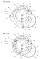
Fig. 11 is an explanatory diagram of first and second modifications regarding a receiving plate of the small power generator. -
Fig. 12 is an explanatory diagram of a third modification regarding the receiving plate of the small power generator. -
Fig. 13 is an explanatory diagram of a fourth modification regarding the receiving plate of the small power generator. - Hereinafter, preferred embodiments of a small power generator and a portable electronic apparatus of the present invention will be described in detail with reference to
Figs. 1 to 13 . -
Fig. 1 is a diagram showing the configuration of the appearance of a mobile phone (portable electronic apparatus) 100 in which asmall power generator 1 is mounted. As shown inFig. 1 , in the case of the portableelectronic apparatus 100 in which a display unit or an operation unit is disposed on the entire surface as smart phones, thesmall power generator 1 is mainly disposed on the back surface of ahousing 101. - In the
small power generator 1, arotary dial 31 is disposed in the middle of the surface, and therotary dial 31 can be turned by hands or fingers put on a plurality ofrotary dial protrusions 33 radially formed on the surface. - By turning the
rotary dial 31, a rotor of an inner rotor typepower generation unit 6, which is disposed inside thesmall power generator 1, is rotated by the rotational force through at least one intermediate gear. As a result, electric power is generated to charge the power supply for the portableelectronic apparatus 100 or charge the spare power supply (for example, a secondary battery or a large-capacity capacitor). - By rotating the
rotary dial 31 about 1 minute, thesmall power generator 1 can generate electric power to the extent that the standby state (monitoring of incoming calls or e-mails and incoming call processing when there is an incoming call) can be maintained for 10 minutes in the case of a mobile phone although this depends on the ratio of the gear for transmitting rotational power or the size of thesmall power generator 1. That is, by the rotation of therotary dial 31, apermanent magnet 65 of the rotor portion is rotated at 3000 rpm to 7000 rpm. By this rotational speed, it is possible to supply a voltage of 3 V to 5 V and a sufficient current for charging. - The
small power generator 1 of the present embodiment is formed in the size of 3 square centimeters to 5 square centimeters and 6 mm to 10 mm in thickness, and accordingly miniaturization and small thickness are realized. - In addition, as a configuration for miniaturization and small thickness, the
small power generator 1 includes an intermediate gear in order to transmit the rotational force of therotary dial 31 to a rotatingunit 3, and at least one of the shafts of the intermediate gear is provided between a plurality ofcore windings 67 circularly disposed in astator core 66 of thepower generation unit 6. Thus, in the present embodiment, the planar size is reduced by providing the shaft of the intermediate gear inside the stator core of the inner rotor type power generator. - In addition, since all components (receiving
unit 4 for supporting the rotary shaft, atransmission unit 5 for transmission of rotation, and the power generation unit 6) required for power generation are disposed on a more inner side than the outer diameter (outer periphery) of therotary dial 31, the planar size can be reduced. - In addition, since a
dial shaft 32 of therotary dial 31 and arotor shaft 61 of thepower generation unit 6 are not disposed on the same axis but disposed so as to be shifted from each other in a plane (disposed so as to be spaced apart from each other), both the shafts can be supported by acommon receiving plate 42. Therefore, it is possible to reduce the overall thickness. -
Fig. 2 is a cross-sectional view taken along each axis of thesmall power generator 1 in a first embodiment. - In
Fig. 3 , in order to clarify the location of each unit that forms the small power generator, a corresponding location inFig. 2 is painted in black. -
Fig. 4 shows a state (a) when a small power generator is viewed from the front and a state (b) where a rotating unit is removed. - As shown in
Figs. 2 and3 , thesmall power generator 1 is configured to include ahousing unit 2, the rotatingunit 3, thereceiving unit 4, thetransmission unit 5, and thepower generation unit 6. - As shown in
Fig. 4 , thesmall power generator 1 is formed in a rectangular shape of 3 cm to 5 cm, and four corners are fixed byscrews 24. - In addition, in the cross-sectional view shown in
Fig. 2 , a cross-section along the broken line passing through each axis is shown (diagram on the right side), and a state screwed by thescrew 24 is shown in a diagram on the left side. - As shown in
Fig. 3(a) , thehousing unit 2 is a housing in which each of therotating unit 3 to thepower generation unit 6 of thesmall power generator 1 is housed. - The
housing unit 2 is configured to include abase 21, anintermediate plate 22, acover 23, and thescrew 24 for fixing these. Thebase 21, theintermediate plate 22, and thecover 23 have the same rectangular shape. In four corners of each of thebase 21, theintermediate plate 22, and thecover 23, screw holes for fixing with thescrew 24 are formed at positions where the central axes are the same. - In the
base 21, a bearing hole for pivotally supporting therotor shaft 61 passes through a position shifted from the center (intersection of diagonals). - In addition, since the
dial shaft 32 of therotary dial 31 is disposed at the center of thebase 21, thedial shaft 32 and therotor shaft 61 are disposed at positions shifted from each other. Therefore, since both theshafts common receiving plate 42, it is possible to reduce the thickness. - A
first recess 21a, which has a circular shape having a radius r1 with a bearing hole for therotor shaft 61 as the center, is formed in thebase 21, and asecond recess 21b, which has a radius r2 (< r1) with the same bearing hole as the center, is further formed below thefirst recess 21a. - A housing portion of the
power generation unit 6 is formed by the first andsecond recesses - In addition, a circular
base step portion 21c is formed by the bottom surface of thefirst recess 21a and the peripheral surface of thesecond recess 21b, and thestator core 66 is placed on thebase step portion 21c. - In addition, on the circular bottom surface formed in the
second recess 21b, a bearing hole for pivotally supporting atransmission shaft 51, which is a shaft of the intermediate gear, passes through a position at a predetermined distance in a central direction from the inner peripheral surface. - Then, since the
transmission shaft 51 is disposed between thecore windings 67 of the stator core 66 (inside the stator core 66), it is possible to reduce the planar size of the small power generator 1 (refer toFig. 5(a) ). - In addition, as shown in
Fig. 5(b) , it is possible to provide acutout portion 66c by cutting a part of the inside of acircular portion 66a away and dispose thetransmission shaft 51 such that a part of thetransmission shaft 51 fits into thecutout portion 66c. - In addition, although not shown in the diagrams, when the diameter of the
transmission shaft 51 is smaller than the width of thecircular portion 66a, it is also possible to provide a through hole of thetransmission shaft 51 in thecircular portion 66a and dispose thetransmission shaft 51, which passes through the through hole, in thebase 21. In this case, thetransmission shaft 51 is pivotally supported by an oil-retainingbearing 52 disposed in thebase step portion 21c of thebase 21. - In addition, the
transmission shaft 51 may be disposed on thecircular portion 66a by providing the oil-retainingbearing 52, which pivotally supports thetransmission shaft 51, in thecircular portion 66a. - Three strut holes for a
strut 41 are formed in portions of the base 21 excluding thefirst recess 21a. - The
intermediate plate 22 is disposed on the upper side where thefirst recess 21a of thebase 21 is formed. - The
intermediate plate 22 has a rectangular shape. At the center of theintermediate plate 22, a circular hole having a diameter slightly smaller than the maximum outer diameter of therotary dial 31 is provided. - On a surface of the
intermediate plate 22 that is in contact with thebase 21, a throughrecess 22a penetrating to the outside from the inside of the circle diameter hole is provided. By the upper surface of thebase 21 and the throughrecess 22a, a through hole penetrating from the inside to the outside is formed on the side surface of thehousing unit 2. - A
substrate 69 for extracting the electric power generated by thepower generation unit 6 is disposed in the throughrecess 22a. Therefore, the depth of the throughrecess 22a is approximately the thickness of thesubstrate 69. - In addition, the
intermediate plate 22 and the base 21 may be integrally formed, and thesubstrate 69 for extracting the generated electric power to the outside or a through hole, through which wiring lines pass, may be provided on the side surface or the bottom surface. In this case, a circular recess for therotary dial 31 is further formed above thefirst recess 21a. The center of this circular recess is matched with the center of therotary dial 31. - The
cover 23 is disposed above thebase 21. - The
cover 23 has the same rectangular shape as thebase 21 and theintermediate plate 22 when thesmall power generator 1 is produced as an independent product. However, for example, when thesmall power generator 1 is built in a portable electronic apparatus, such as a mobile phone, a smart phone, or a sound data reproduction apparatus, it is also possible to use a cover that forms a housing of the portable electronic apparatus. - The
cover 23 is formed in a circular shape such that the cross-section has an inverted L shape, and is configured to include a circular portion that forms apressing portion 23c and a peripheral wall portion erected in the outer periphery. - That is, a
circular recess 23a having a diameter slightly larger than the maximum outer diameter of therotary dial 31 is formed at the center of thecover 23. In addition, acircular dial hole 23b having a diameter slightly smaller than the maximum outer diameter of therotary dial 31 is formed in the middle of the bottom surface of thecircular recess 23a. In addition, thepressing portion 23c for pressing therotary dial 31 is formed by the remaining bottom portion of therecess 23a. - As shown in
Fig. 3(b) , therotating unit 3 is a member that is disposed in the middle of the upper portion of thesmall power generator 1 and is used when a user performs a rotation operation to generate the electric power. - The
rotary dial protrusion 33 is formed on the upper surface of therotating unit 3 so that a finger is put on therotary dial protrusion 33 when the user performs a rotation operation. As shown inFig. 4(a) , a plurality of (in the present embodiment, 10)rotary dial protrusions 33 are radially provided. - In the present embodiment, since the strength of the
rotary dial 31 can be increased by forming a plurality ofrotary dial protrusions 33 radially, it is possible to form therotary dial 31 to be thin. - A shaft hole for a sliding bearing is formed at the inside center of the
rotating unit 3, and is pivotally supported by thedial shaft 32. - On the inner surface of the
rotating unit 3, acircular recess 34 is formed concentrically with the shaft center of thedial shaft 32. Adriving gear 35 is formed on the inner peripheral wall of thecircular recess 34. - The
driving gear 35 is integrally formed on the inner peripheral wall of thecircular recess 34 by molding, sintering, and the like. However, thedriving gear 35 that is separately formed in a ring shape may be fixed to the inner peripheral wall of thecircular recess 34. - The rotational driving force of the
rotary dial 31 is transmitted through thedriving gear 35. - In a peripheral end portion of the
rotating unit 3, a thincircular engaging portion 36 is formed over the entire periphery. The circular engagingportion 36 is covered by thepressing portion 23c of thecover 23 with a predetermined gap interposed therebetween so that therotary dial 31 does not come off. - On the inner surface of the circular engaging
portion 36, that is, on the outer peripheral side of the surface of therotary dial 31 facing thebase 21, a circular slidingprotrusion 37 is formed over the entire periphery, and the slidingprotrusion 37 is in contact with theintermediate plate 22. In addition, a contact portion of the slidingprotrusion 37 and theintermediate plate 22 slide when therotary dial 31 is rotated. - Thus, in the
rotary dial 31, the center is supported by the receivingplate 42 on thedial shaft 32, and the outer peripheral side of the bottom surface facing the receivingplate 42 is supported by theintermediate plate 22. Therefore, since the strength of therotary dial 31 can be increased, it is possible to form therotary dial 31 to be thin. - As shown in
Fig. 3(c) , the receivingunit 4 is a member that is disposed between thehousing unit 2 and therotating unit 3 and is for pivotally supporting each shaft (thedial shaft 32, thetransmission shaft 51, and the rotor shaft 61) of thesmall power generator 1. - The receiving
unit 4 is configured to include threestruts 41, the receivingplate 42, and ascrew 43. - As shown in
Fig. 2 , thestruts 41 are fixed to three strut holes formed in thebase 21 by driving. -
Fig. 4(b) shows a state where therotary dial 31 is detached from a state shown inFig. 4(a) when thesmall power generator 1 is viewed from the top. Three struts 41 are provided at positions, which do not overlap the receivingunit 4 and thetransmission unit 5, in thebase 21 on the inner side of the intermediate plate 22 (refer to thescrew 43 attached to thestrut 41 inFig. 4(b) ). Three struts 41 are disposed such that the shaft center of thedial shaft 32 is positioned at the approximately central portion of the three points. Accordingly, the threestruts 41 can stably receive the force generated during the rotation of therotary dial 31. - In addition, the
strut 41 may be screwed to thebase 21 by forming a screw on the outer peripheral surface of thestrut 41. - At the other ends of the three
struts 41 fixed to thebase 21, the receivingplate 42 having an approximately triangular shape whose three sides are curved outward is disposed, and is fixed to thestrut 41 by thescrew 43. - A fixing
hole 42a for thedial shaft 32, a shaft hole for therotor shaft 61, and a shaft hole for thetransmission shaft 51 are formed at corresponding positions in the receivingplate 42. - In addition, as shown in
Fig. 2 , since thedial shaft 32 is disposed upward from the receivingplate 42, and therotor shaft 61 is disposed downward from the receivingplate 42, both the shafts can be fixed and pivotally supported on the same receivingplate 42. As a result, thesmall power generator 1 can be made thin. - In the
dial shaft 32, the lower side of the bearing portion of thedial shaft 32 is fixed to the fixing hole portion by driving. However, thedial shaft 32 may be fixed by other methods, such as welding and screw fixing. - As shown in
Fig. 3(d) , thetransmission unit 5 is a member for transmitting the rotation of therotary dial 31 to therotor shaft 61 of thepower generation unit 6. - The
transmission unit 5 is configured to include thetransmission shaft 51, the oil-retainingbearing 52, an oil-retainingbearing 53, a secondintermediate gear 54, and a firstintermediate gear 55. - One end of the
transmission shaft 51 is pivotally supported on thebase 21 by the oil-retainingbearing 52, and the other end side is pivotally supported on the receivingplate 42 by the oil-retainingbearing 53. - As shown in
Figs. 2 and4(b) , the oil-retainingbearing 53 side of thetransmission shaft 51 penetrates the receivingplate 42, and the firstintermediate gear 55 is fixed to the end by spline or using a key and a groove. - The first
intermediate gear 55 is located in thecircular recess 34 of therotary dial 31, and meshes with the driving gear 35 (refer toFigs. 2 and4(a) ). - In addition, the second
intermediate gear 54 is integrally formed between both the pivotally supported portions of thetransmission shaft 51, and the secondintermediate gear 54 meshes with a drivengear 62 formed on the rotor shaft 61 (refer toFigs. 2 and5(a) ). In addition, the secondintermediate gear 54 may be formed separately from thetransmission shaft 51 and be attached to thetransmission shaft 51 using a key and a groove or by spline. - As shown in
Fig. 3(e) , thepower generation unit 6 is a member that is housed in thehousing unit 2 and generates electric power by receiving the rotational force of therotary dial 31 through thetransmission unit 5 and rotating a permanent magnet. - The
power generation unit 6 is configured to include a rotor portion, a stator portion, and thesubstrate 69. Thepower generation unit 6 is a stator core and inner rotor type power generator, and the number of magnetic poles of the permanent magnet and the number of protruding poles of the stator core are the same 10. - As shown in
Figs. 2 and6(a) , the rotor portion is configured to include therotor shaft 61, the drivengear 62, oil-retainingbearings member 64, and thepermanent magnet 65. In addition, the stator portion is configured to include thestator core 66 and the core winding 67. - One end of the
rotor shaft 61 is pivotally supported on thebase 21 by the oil-retainingbearing 63a, and the other end is pivotally supported on the receivingplate 42 by the oil-retainingbearing 63b. The drivengear 62 meshing with the secondintermediate gear 54 is integrally formed on the outer peripheral surface of therotor shaft 61 on the side of the receivingplate 42. The drivengear 62 may also be separately formed and be fixed to therotor shaft 61 by spline or using a key and a groove. - The disc-shaped magnetic holding
member 64 is attached to the base 21 side of therotor shaft 61. In the magnetic holdingmember 64, a plurality (inFig. 6(a) ,5 ) of through holes are provided for weight reduction. - A step is formed on the outer peripheral edge of the magnetic holding
member 64, and the ring-shapedpermanent magnet 65 is fixed to the step portion. - The
permanent magnet 65 may be integrally molded and sintered in a ring shape, or an individual magnet may be arranged in a ring shape for each magnetic pole. For thepermanent magnet 65 of the present embodiment, a magnetic material in a powder form is put into a mold and heat-treated for sintering. However, a magnetic material may also be heat-treated together with resin (bond) for resin formation or compression formation. - The magnetic material formed in the ring shape is attached to the magnetic holding
member 64 fixed to therotor shaft 61 and is magnetized from the outer peripheral surface side in this state, thereby forming thepermanent magnet 65. Thepermanent magnet 65 that has been magnetized becomes a segment magnet whose magnetic field is oriented from the inside toward the outside in a radial direction and which is divided according to the number of poles. - As a magnetic material of the
permanent magnet 65, rare earth magnets are often used. Among the rare earth magnets, an Nd-Fe-B based bond magnet or an Sm-Fe-N based bond magnet that is an isotropic magnetic material may be used. In the present embodiment, however, an anisotropic magnet is used so that the sufficient magnetic force is obtained even if the rotor portion is reduced in size. - That is, as a magnetic material, an Sm-Co (samarium cobalt) based magnetic material that can generate a large amount of magnetic flux even if the thickness in a radial direction is small and that has large coercive force is used. In this case, when realizing the anisotropy using the Sm-Co based magnetic material, it is possible to generate a large amount of magnetic flux even if the thickness is small by performing magnetization after aligning the magnetic axis of the entire magnetic material by magnetic field orientation.
- The
permanent magnet 65 is formed so that the number of magnetic poles is 10 as shown inFig. 6(a) . In addition, the display of S and N shown inFig. 6(a) is for displaying the pole facing the core winding 67, and the opposite side (on the center side) of each is an opposite pole. - The
permanent magnet 65 is magnetized as follows using a magnetizingyoke 68a. -
Fig. 6(b) is a perspective view showing a state in which a rotor portion is magnetized by the magnetizingyoke 68a. - As shown in
Fig. 6(b) , in the magnetizingyoke 68a, protruding portions of the same number as the number of poles (in the present embodiment, 10 poles) of thepermanent magnets 65 are formed toward the center from the circular portion, and a magnetizingcoil 68b is wound around the protruding portion in a thickness to withstand a large current. - The magnetizing
yoke 68a is formed in a thickness of about four times the thickness of a magnetic material 65b in order to strongly magnetize (fully magnetize) the magnetic material 65b (permanent magnet 65). - A rotor portion in which the magnetic holding
member 64 and a circular magnetic material (member that becomes thepermanent magnet 65 after magnetization) 65a are fixed to therotor shaft 61 is disposed inside the magnetizingyoke 68a. Accordingly, the magnetizingcoils 68b are disposed opposite each other on the outer peripheral surface of themagnetic material 65a. - By making a large current flow through the magnetizing
coil 68b in this state, themagnetic material 65a is fully magnetized. As a result, thepermanent magnet 65 having 10 poles whose magnetic field is oriented from the inside toward the outside in a radial direction is formed. - On the other hand, as shown in
Figs. 2 and6(a) , thestator core 66 that forms the stator portion is configured to include thecircular portion 66a and protrudingportions 66b. - As shown in
Fig. 6(a) , a plurality of protrudingportions 66b are disposed toward the center from the inner peripheral surface of thecircular portion 66a. - The protruding
portions 66b are provided so as to match the predetermined number of poles. In the present embodiment, since the same number as the number of poles of thepermanent magnet 65 is adopted as the predetermined number of poles, 10 protrudingportions 66b are provided to set the number of poles to 10. - The protruding
portion 66b has a shape that extends toward the center from thecircular portion 66a and also extends to both sides in the peripheral direction at its end. The distal end of the protrudingportion 66b faces the outer peripheral surface of thepermanent magnet 65 with a gap of a predetermined distance interposed therebetween. In addition, the core winding 67 is wound around the portion of the protrudingportion 66b extending toward the center. - The diameter of the inner periphery (hereinafter, referred to as an inner diameter) of the
stator core 66 formed at the tips of the 10 protrudingportions 66b is selected in a range equal to or greater than 10 mm and equal to or less than 20 mm as a preferable size for miniaturizing thesmall power generator 1, and more preferably, selected in a range equal to or greater than 10 mm and equal to or less than 15 mm. - On the other hand, the thickness of the
stator core 66 is selected in a range equal to or greater than 0.8 mm and equal to or less than 1.4 mm. - In addition, as the number of poles n (the number of protruding
portions 66b and the number of core windings 67) of thestator core 66, when the inner diameter of thestator core 66 is equal to or greater than 10 mm and equal to or less than 15 mm, 8 to 12 poles are preferably selected, and more preferably, 10 poles are selected. When the inner diameter is equal to or greater than 15 mm and equal to or less than 20 mm, 10 to 14 poles are preferably selected, and more preferably, 12 poles are selected. - In the present embodiment, the
stator core 66 with 10 poles which has an inner diameter of 13 mm, an outer diameter of 22 mm, and a thickness of 1 mm is used. - Here, the reason for selecting the number of poles in the
stator core 66 will be described with reference toFigs. 7 and8 . -
Fig. 7 shows the shape of thestator core 66 when the number (the number of poles) of protrudingportions 66b is changed. - In
Fig. 7 , the shapes of thestator cores 66 having 4 poles, 6 poles, 8 poles, 10 poles, 12 poles, 14 poles, and 16 poles are expressed by providing 4 to 16 slots in therespective stator cores 66. - In all of the
stator cores 66, the inner diameter, the outer diameter, and the thickness (product thickness) are set to 13 mm, 22 mm, and 1 mm, respectively, in order to unify the conditions of power generation. In addition, the slot width (width between the distal ends of the adjacent protrudingportions 66b) of eachstator core 66 is set to be the same for all of thestator cores 66 since a predetermined width required for winding processing is needed. -
Fig. 8 shows the electric power generated when eachstator core 66 shown inFig. 7 is used. -
Fig. 8 shows the electric power when winding is performed for thestator core 66 having each shape shown inFig. 7 and a rotor having the same size is disposed inside eachstator core 66 and is rotated at 5000 rpm. - Generally, it is possible to obtain high electric power as the number of poles increases. However, when the inner diameter of the
stator core 66 is set to 13 mm by miniaturization, as shown inFig. 8 , electric power generated when the number of poles is 10 is the highest, electric power generated when the number of poles is 8 that is the very next lower number of 10 poles is the second highest, and electric power generated when the number of poles is 12 that is the very next higher number of 10 poles is the third highest. - Thus, the generated electric power is not necessarily increased in proportion to a simple increase in the number of poles, and the reason can be considered as follows.
- That is, if the size of the
stator core 66 is not taken into consideration, when the permanent magnet is rotated at the same speed, the speed of the magnetic flux interlinking the core winding 67 increases and accordingly the generated electric power increases as the number of magnetic poles of the magnet increases. - However, with the miniaturization of the
stator core 66, the cross-sectional area (cross-sectional area of the core) of the core winding 67 decreases as the number of protrudingportions 66b (the number of core poles) increases, and the magnetic flux is saturated. For this reason, the magnetic flux of the core winding 67 per cross-section decreases as the number of poles increases. - Therefore, when the
small stator core 66 having an inner diameter of 10 mm to 20 mm is used, the number of poles that can be adopted according to the range of the inner diameter size and the optimal number of poles n are present. - Thus, in the inner rotor type power generator in which the inner diameter of the
stator core 66 is equal to or greater than 10 mm and equal to or less than 20 mm, it can be seen that the electric power generated in the case of the optimal number of poles n is the highest, the generated electric power decreases as the number of poles decreases from n, and the generated electric power decreases as the number of poles increases even if the number of poles is larger than n. - The optimal number of poles n is determined by the inner diameter of the
stator core 66. When the inner diameter is equal to or greater than 10 mm and equal to or less than 15 mm, n = 10. In this case, power generation that can withstand practical use is obtained in the range of the number of poles of 8 to 12. - On the other hand, when the inner diameter is equal to or greater than 15 mm and equal to or less than 20 mm, n = 12. In this case, power generation that can withstand practical use is obtained in the range of the number of poles of 10 to 14.
- The
stator core 66 is manufactured by laminating and fixing a plurality of thin plates each of which has a shape in which thecircular portion 66a and the protrudingportion 66b are integrally formed and is insulated by an insulation coating or the like. Specifically, thestator core 66 is formed of a laminated silicon steel plate. - In addition, various materials and shapes in the inner rotor type power generator can be adopted for the
stator core 66. For example, the protrudingportion 66b manufactured separately may be fixed to thecircular portion 66a. - The core winding 67 is wound in series around each protruding
portion 66b. - In the present embodiment, a structure is adopted in which the
stator core 66 is disposed on the outer periphery of the inner rotor. Therefore, since a plurality ofcore windings 67 can be radially disposed inside thecircular portion 66a, it is possible to increase the coil winding length (the length of the winding) while reducing the size of each core winding 67. As a result, it is possible to generate a large amount of electric power. - As shown in
Fig. 5(a) , thesubstrate 69 that forms a stator portion passes through the throughrecess 22a from the outside of thehousing unit 2, and is disposed on the twocore windings 67. - Two wiring lines are provided by printing or the like on the
substrate 69, and both ends of the core winding 67 wound in series are connected to two wiring lines so that the electric power generated by thepower generation unit 6 is extracted to the outside. - When the
small power generator 1 is built into a portable electronic apparatus, such as a mobile phone, a side (not shown) of thesubstrate 69 is connected to a secondary battery or a spare power supply (a secondary battery, a large-capacity capacitor, or the like) of the portable electronic apparatus. - In addition, when the
small power generator 1 is used as a spare external power supply, wiring lines including a terminal connected to various apparatuses may also be used instead of thesubstrate 69. - The assembly procedure of the
small power generator 1 configured as described above will be described below. - (1) First, fix the three
struts 41 to thebase 21. - (2) Then, dispose the
stator core 66 of thepower generation unit 6 in thebase step portion 21c of thebase 21. In this case, perform positioning such that thesubstrate 69 attached to thestator core 66 matches the throughrecess 22a of theintermediate plate 22. - (3) In addition, pivotally support the lower end of the
rotor shaft 61, to which thepermanent magnet 65 and the magnetic holdingmember 64 are fixed, on thebase 21 by the oil-retainingbearing 63a. - (4) Then, pivotally support the
transmission shaft 51 on thebase 21 by the oil-retainingbearing 52, and make the drivengear 62 of therotor shaft 61 mesh with the secondintermediate gear 54. - (5) Then, pivotally support the upper end of the
rotor shaft 61 on the receivingplate 42, to which thedial shaft 32 is fixed, by the oil-retainingbearing 63b, pivotally support the upper portion of thetransmission shaft 51 by the oil-retainingbearing 53, and fix the receivingplate 42 to thestrut 41 using thescrew 43. - (6) Then, attach the first
intermediate gear 55 to thetransmission shaft 51 from the upper side of the receivingplate 42. - (7) Then, place the
intermediate plate 22 on thebase 21. In this state, thesubstrate 69 comes to the outside from the throughrecess 22a. - (8) Then, place the
rotary dial 31 on theintermediate plate 22, and pivotally support therotary dial 31 on thedial shaft 32. - (9) Finally, place the
cover 23 on theintermediate plate 22, and screw the four corners of thebase 21, theintermediate plate 22, and thecover 23 using thescrew 24. - The operation of power generation by the
small power generator 1 configured as described above will be described below. - When generating the electric power, the user puts his or her finger on the
rotary dial protrusion 33 to rotate therotary dial 31. - When the
rotary dial 31 is rotated, the rotation is transmitted to thetransmission shaft 51 through the firstintermediate gear 55 meshing with thedriving gear 35. The rotation of thetransmission shaft 51 is further transmitted to therotor shaft 61 through the drivengear 62 meshing with the secondintermediate gear 54, thereby rotating thepermanent magnet 65. - Thus, by the rotation of the
rotary dial 31, the rotational speed is increased by the gear ratio of the gears and thepermanent magnet 65 of the rotor portion is rotated (range of 3000 rpm to 7000 rpm). Therefore, it is possible to supply a voltage of 3 V to 5 V and a sufficient current for charging. - The electric power generated by the
power generation unit 6 charges the power supply through wiring lines of thesubstrate 69. - Next, a second embodiment in the
small power generator 1 will be described. - In the
small power generator 1 of the second embodiment, the transmission path of the rotational power of therotary dial 31 is different from that in the first embodiment. That is, all of thedriving gear 35, the firstintermediate gear 55, the secondintermediate gear 54, and the drivengear 62 that form a two-stage gear mechanism are formed using spur gears in the first embodiment described above, but an internal gear is provided in therotary dial 31 in the second embodiment. - Hereinafter, details of the second embodiment will be described focusing on the differences from the first embodiment with reference to
Figs. 9 and10 . - In the
small power generator 1, a circular recess around thedial shaft 32 is provided inside arotary dial 31b so that aperipheral wall portion 38 is formed on the entire surface of the outer periphery, and a driveinternal gear 35b is formed on the inner peripheral surface of theperipheral wall portion 38. Theperipheral wall portion 38 is disposed in a circular hole of theintermediate plate 22. - In addition, a circular
engaging portion 36b is formed over the entire outer periphery of theperipheral wall portion 38, and the bottom surface of the circularengaging portion 36b slides on theintermediate plate 22. Thus, the outer peripheral portion of therotary dial 31b is supported. - An
intermediate gear 54b to directly transmit the rotation from the driveinternal gear 35b of therotary dial 31b to the drivengear 62 of therotor shaft 61 is formed on thetransmission shaft 51 of the second embodiment. - That is, the
intermediate gear 54b formed on thetransmission shaft 51 meshes with the driveinternal gear 35b formed inside theperipheral wall portion 38 of therotary dial 31b and meshes with the drivengear 62 formed on therotor shaft 61, thereby functioning as an idle gear. - As shown in
Figs. 9 and10 , also in the second embodiment, thetransmission shaft 51 of theintermediate gear 54b is provided inside the stator core 66 (outside the rotor portion), specifically, between thecore windings 67 of thestator core 66 in order to reduce the planar size of thesmall power generator 1. - In addition, also in the second embodiment, as shown in
Fig. 10 , all of the receivingunit 4, thetransmission unit 5, and thepower generation unit 6 except for a part of thesubstrate 69 are formed within the maximum diameter of therotary dial 31b. - In addition, an end of the
transmission shaft 51 of the second embodiment is pivotally supported on the receivingplate 42 by the oil-retainingbearing 53. - Thus, in the second embodiment, it is possible to make the
rotary dial 31b thin since the firstintermediate gear 55 is not necessary, unlike the first embodiment in which the end of thetransmission shaft 51 penetrates from the receivingplate 42 and the firstintermediate gear 55 is fixed to the end. As a result, it is possible to reduce the overall thickness of thesmall power generator 1. - In addition, in the first embodiment, a plurality of
rotary dial protrusions 33 arranged radially with thedial shaft 32 as the center are provided as a structure to assist the rotation operation when rotating therotary dial 31. In the second embodiment, however, arotary dial recess 33b is adopted. - In the
rotary dial recess 33b, a circular recess is provided in onerotary dial 31b, and the user puts his or her finger on the recess to rotate therotary dial 31b. - In addition, in the
rotary dial 31 in the first embodiment, it is possible to adopt therotary dial 31 instead of therotary dial protrusion 33. In addition, conversely, therotary dial protrusion 33 of the first embodiment may be adopted in therotary dial 31b of the second embodiment. - Next, modifications of the first and second embodiments will be described with reference to
Figs. 11 to 13 . - In these modifications, the shape of the receiving
unit 4 of thesmall power generator 1 is changed. Although the following explanation will be given with the first embodiment as an example, this can also be similarly applied to the second embodiment described above. - In the
small power generator 1 of both the embodiments described above, as shown inFig. 4(b) , three shafts of thedial shaft 32, therotor shaft 61, and thetransmission shaft 51 are pivotally supported on the receivingplate 42, and allstruts 41 for fixing the receivingplate 42 to the base 21 are disposed outside thestator core 66. - In first to third modifications of these modifications, at least one
strut 41 of the plurality ofstruts 41 is disposed inside the stator core 66 (outside the rotor portion) and is fixed to thebase 21. - In addition, although the arrangement of the
dial shaft 32, therotor shaft 61, and thetransmission shaft 51 in each modification is the same as in the first and second embodiments, thedial shaft 32, therotor shaft 61, and thetransmission shaft 51 may be disposed at different positions. However, thetransmission shaft 51 is disposed in thestator core 66 for the miniaturization of thesmall power generator 1. - In the first modification, as shown in
Fig. 11(a) , one of threestruts 41a is disposed between thecore windings 67. In the example shown inFig. 11(a) , astrut 41c is disposed at the same position as in the first embodiment. However, astrut 41b is disposed outside thestator core 66 but disposed closer to thestator core 66 than in the first embodiment. - Thus, by disposing the
strut 41a of the plurality ofstruts 41a to 41c in thestator core 66, the receivingplate 42 can be made small. Accordingly, it is possible to reduce the weight. In addition, it is also possible to reduce the planar size of thesmall power generator 1. - In the second modification, as shown in
Fig. 11(b) , all struts 41a to 41c are disposed inside thestator core 66. - Accordingly, a total of four of the three
struts 41a to 41c and thetransmission shaft 51 are disposed in thestator core 66. - In addition, in the second modification, among a total of 10
core windings 67, threecore windings 67 are disposed between thestruts core windings 67 are disposed between thestruts core windings 67 are disposed between thestruts plate 42 with good balance. In addition, in order to improve the balance of thetransmission shaft 51 with respect to thestruts core windings 67 are placed between thestruts transmission shaft 51 is disposed therebetween. - In addition, in the second modification, the receiving
plate 42 can be placed within the outer peripheral surface of thestator core 66 by disposing all of the threestruts 41a to 41c in thestator core 66. - Next, a third modification will be described with reference to
Fig. 12 . - Also in the third modification, all of the three
struts 41a to 41c are disposed between thecore windings 67. - In the third modification, the
strut 41 is disposed between thecore windings 67 by increasing the diameter of thestator core 66. Thus, by enlarging thestator core 66, it is possible to further increase the number of windings and to obtain a high voltage. - In addition, for the winding method of the core winding 67, the case of series winding has been described. In the third modification, however, since the protruding
portion 66b can be made long, it is also possible to adopt a configuration of overlap winding. - In the first and second embodiments and the first and second modifications, the case has been described in which the
rotating unit 3, the receivingunit 4, and thetransmission unit 5 are disposed within the outer peripheral surface of therotary dial 31 except for a part of thesubstrate 69. However, as shown in the third modification, it is possible to adopt a structure in which a part of thestator core 66 protrudes from the outer peripheral surface of therotary dial 31. - Thus, when a structure is adopted in which the
stator core 66 protrudes to the outside of therotary dial 31, it is possible to realize the same size as thesmall power generator 1 in the first embodiment by matching a virtual line segment connecting the axes of both with the diagonal line of thehousing unit 2. That is, it is possible to avoid an increase in the overall size by enlarging thestator core 66 such that thestator core 66 does not protrude in the apex direction of thehousing unit 2. - In addition, although the case where all struts 41a to 41c are disposed between the core windings 67 has been described in the modification shown in
Fig. 12 , it is possible to adopt a configuration in which one of thestruts 41a to 41c is disposed between thecore windings 67. - Although the case where at least one
strut 41 is disposed between the core windings 67 has been described in the first to third modifications described above, at least onestrut 41 may be disposed on thecircular portion 66a. - In this case, the
strut 41 may be fixed to thecircular portion 66a itself, or thestrut 41 may pass through thecircular portion 66a and the base 21 to be fixed. - Next, a fourth modification will be described with reference to
Fig. 13 . - In the first embodiment and the modifications described above, a configuration is adopted in which the
strut 41 is fixed to thebase 21 and the receivingplate 42 is fixed to thestrut 41 on the inside of theintermediate plate 22. On the other hand, in the fourth modification, thestrut 41 is eliminated, and the receivingplate 42 is supported and fixed by thehousing unit 2. - Also in the fourth modification, the support positions of the
dial shaft 32, therotor shaft 61, and thetransmission shaft 51 are the same as in the first embodiment. - In the fourth modification, as shown in
Fig. 13 , the outer shape of a receivingplate 45 is the same as the outer shape of thehousing unit 2, and the receivingplate 45 is disposed between theintermediate plate 22 and thecover 23. Screw holes are formed at four corners of the receivingplate 45 in the same manner as in thehousing unit 2, and the receivingplate 45 is fixed together with thehousing unit 2 by thescrews 24. - Thus, in the fourth modification, since there is no
strut 41, it is possible to reduce the number of manufacturing components. Therefore, it is possible to simplify the manufacturing process. - In the fourth modification, the sliding
protrusion 37 of therotary dial 31 slides on the surface of the receivingplate 45. - In addition, although the area of the outer shape of the receiving
plate 45 becomes large compared with the receivingplate 42 described in the first embodiment or the modifications, a through hole may be provided in the receiving plate 45 (inside is cut) within the range not causing problems to the strength to support thedial shaft 32, thestrut 41, and therotor shaft 61. - In addition, it is also possible to use the receiving
plate 45 configured to include a central support plate portion of the area including thedial shaft 32, thestrut 41, and therotor shaft 61, a circular portion whose shape in plan view is approximately the same as theintermediate plate 22, and a connecting portion that connects the central support plate portion and the circular portion at three or more locations. - For example, it is possible to adopt a structure in which the shape of the central support plate portion of the receiving
plate 45 is the same as the shape of the receivingplate 42 shown inFig. 4(b) and the central support plate portion is connected to the circular portion by three connecting portions extending from the central support plate portion in a direction of the line segment connecting thescrew 43 from the axis of therotary dial 31. - In addition, in the fourth modification shown in
Fig. 13 , thesmall power generator 1 having the same thickness as in the first embodiment or the modifications described above is formed by reducing the thickness of theintermediate plate 22 by the thickness of the receivingplate 45. - On the other hand, the
intermediate plate 22 and the receivingplate 45 may be integrally formed. - In addition, it is also possible to eliminate the
intermediate plate 22, form the base 21 in a thickness including theintermediate plate 22, and form thefirst recess 21a so as to be deep by the thickness. - According to the embodiments and the modifications described above, the following effects can be obtained.
- (1) The plurality of
core windings 67 disposed in a circular shape, thepermanent magnet 65 disposed on the inner periphery of the core windings 67, and a gear train for rotating thepermanent magnet 65 are provided, and the rotary shaft (transmission shaft 51) of at least one gear of the gear train is disposed between the plurality ofcore windings 67 disposed as described above. Thus, it is possible to reduce the planar size by disposing the rotary shaft of the gear between thecore windings 67. - (2) In addition, by disposing the plurality of
core windings 67 radially in the circular ring, it is possible to increase the overall coil winding length while reducing the size of each core winding 67. As a result, it is possible to generate a large amount of electric power. - (3) Since the axis of the
rotary dial 31 and the axis of the rotor portion in thepower generation unit 6 are not the same, holding members (thedial shaft 32 and the oil-retainingbearing 63a) used in rotation support portions of therotary dial 31 and the rotor portion are shifted from each other in a plane. Therefore, since it is possible to avoid any interference in the thickness direction, it is possible to reduce the thickness. - (4) In addition, in the case of an outer rotor type power generation unit, the apparatus becomes thick since a magnetic holding member (rotor bottom) that holds a permanent magnet is disposed above/below the stator. In the present embodiment, however, since the
permanent magnet 65 and the magnetic holdingmember 64 can be disposed inside thestator core 66 by adopting the inner rotor type, it is possible to reduce the thickness of the apparatus. - (5) In addition, in the embodiments and the modifications described above except for the fourth modification, the
dial shaft 32 of thedriving gear 35 and therotor shaft 61 of the drivengear 62 are disposed within the triangle connecting the three struts 41. Therefore, both shafts can be stably supported by the receivingplate 42. - (6) In the case of the outer rotor type power generator, it is necessary to perform magnetization from the inside of the radially anisotropic magnet molded in a ring shape. However, in the case of a small diameter, it is difficult to dispose a magnetization yoke inside the magnet. For this reason, it is difficult to use an anisotropic magnet with strong magnetic force.
- However, in the inner rotor structure of the present embodiment, since a magnetically oriented split magnet is attached and fixed to the rotor and then the magnetizing
yoke 68a is disposed on the outer periphery, magnetization is easily performed. Therefore, since full magnetization is possible, it is possible to obtain a large amount of electric power by using an anisotropic magnet with strong magnetic force. - While the embodiments and the modifications in the small power generator of the present invention have been described, the present invention is not limited to those described above, and various modifications can be made within the scope as set forth in the claims.
- For example, although the through
recess 22a for thesubstrate 69 is provided in theintermediate plate 22 in the embodiments described above, it is also possible to form theintermediate plate 22 as a circular flat plate and provide a through recess on the upper surface of thebase 21. In this case, since thestator core 66 in which thesubstrate 69 is disposed is attached to thebase 21, the positioning of thesubstrate 69 becomes easy. - In addition, although the configuration in which three struts 41 are provided has been adopted in the embodiments described above, four or
more struts 41 may be provided. - In addition, although the case where the
rotary dial protrusion 33 is provided in therotary dial 31 has been described in the first embodiment and the case where therotary dial recess 33b is provided in therotary dial 31 has been described in the second embodiment, it is also possible to provide a polygonal hole on the surface of therotary dial 31 and insert a lever into the polygonal hole and turn it. In this case, therotary dial 31 can be rotated with a small force by providing the polygonal hole on the outer peripheral side as possible of therotary dial 31. In addition, a plurality of polygonal holes may be provided at different positions in a radial direction (positions where the distances from the center of rotation are different), so that it can be selected according to the preferences of the user whether to turn therotary dial 31 on a large circle with a small force by inserting the lever into a polygonal hole on the outer side or to turn therotary dial 31 on a small circle with a large force by inserting the lever into a polygonal hole on the central side. - In addition, although the case where a shaft hole is formed in the
rotary dial 31 and thedial shaft 32 fits into the shaft hole has been described in the embodiments in which therotary dial 31 is described as a rotation support portion, a shaft may be made to protrude from therotary dial 31 and the shaft may be inserted into shaft holes provided in the receivingplates -
- 1:
- small power generator
- 2:
- housing unit
- 21:
- base
- 21a:
- first recess
- 21b:
- second recess
- 21c:
- base step portion
- 22:
- intermediate plate
- 22a:
- through recess
- 23:
- cover
- 23a:
- recess
- 23b:
- dial hole
- 23c:
- pressing portion
- 24:
- screw
- 3:
- rotating unit
- 31, 31b:
- rotary dial
- 32:
- dial shaft
- 33:
- rotary dial protrusion
- 33b:
- rotary dial recess
- 34:
- circular recess
- 35:
- driving gear
- 35b:
- drive internal gear
- 36, 36b:
- circular engaging portion
- 37:
- sliding protrusion
- 38:
- peripheral wall portion
- 4:
- receiving unit
- 41:
- strut
- 42:
- receiving plate
- 43:
- screw
- 45:
- receiving plate
- 5:
- transmission unit
- 51:
- transmission shaft
- 52, 53:
- oil-retaining bearing
- 54:
- second intermediate gear
- 54b:
- intermediate gear
- 55:
- first intermediate gear
- 6:
- power-generation unit
- 61:
- rotor shaft
- 62:
- driven gear
- 63a, 63b:
- oil-retaining bearing
- 64:
- magnetic holding member
- 65:
- permanent magnet
- 66:
- stator core
- 66a:
- circular portion
- 66b:
- protruding portion
- 66c:
- cutout portion
- 67:
- core winding
- 68a:
- magnetizing yoke
- 68b:
- magnetizing coil
- 69:
- substrate
- 100:
- portable electronic apparatus
- 101:
- housing
Claims (7)
- An inner rotor type small power generator, comprising:a circular stator including a plurality of core windings;a rotor that includes a rotor shaft, in which a driven gear is disposed, and a circular permanent magnet and that is disposed inside the stator;a rotating unit that includes a driving gear and that is rotated by a user at the time of power generation; anda transmission unit that transmits rotation of the driving gear, which is caused by the rotation of the rotating unit, to the driven gear of the rotor shaft through an intermediate gear,wherein at least one rotary shaft of the intermediate gear is disposed outside the rotor within the stator.
- The small power generator according to claim 1,
wherein at least one rotary shaft of the intermediate gear is disposed between the core windings of the rotor. - The small power generator according to claim 1 or 2, further comprising:a receiving plate disposed between the rotating unit and the stator,wherein a rotary shaft of the driving gear, at least one rotary shaft of the intermediate gear, and the rotor shaft are supported on the receiving plate.
- The small power generator according to claim 3,
wherein the rotating unit includes a rotary dial which is disposed in parallel with the stator and in which a circular recess, which is formed concentrically with the driving gear, is formed, and
the driving gear is an external gear formed on an inner peripheral surface of an inner side of the circular recess. - The small power generator according to claim 3,
wherein the rotating unit includes a rotary dial which is disposed in parallel with the stator and in which a circular recess, which is formed concentrically with the driving gear, is formed, and
the driving gear is an internal gear formed on the circular recess. - The small power generator according to claim 4 or 5,
wherein the stator, the rotor, and the transmission unit are disposed on a more inner side than an outer diameter of the rotary dial. - A portable electronic apparatus, comprising:the small power generator according to any one of claims 1 to 6; andstorage means for storing electric power generated by the small power generator.
Applications Claiming Priority (2)
| Application Number | Priority Date | Filing Date | Title |
|---|---|---|---|
| JP2011111443A JP5751623B2 (en) | 2011-05-18 | 2011-05-18 | Small power generator and portable electronic device |
| PCT/JP2012/053873 WO2012157305A1 (en) | 2011-05-18 | 2012-02-17 | Small power generating device and mobile electronic device |
Publications (3)
| Publication Number | Publication Date |
|---|---|
| EP2712067A1 true EP2712067A1 (en) | 2014-03-26 |
| EP2712067A4 EP2712067A4 (en) | 2016-04-27 |
| EP2712067B1 EP2712067B1 (en) | 2017-08-16 |
Family
ID=47176647
Family Applications (1)
| Application Number | Title | Priority Date | Filing Date |
|---|---|---|---|
| EP12785758.9A Not-in-force EP2712067B1 (en) | 2011-05-18 | 2012-02-17 | Small power generating device and mobile electronic device |
Country Status (6)
| Country | Link |
|---|---|
| US (1) | US9621008B2 (en) |
| EP (1) | EP2712067B1 (en) |
| JP (1) | JP5751623B2 (en) |
| KR (1) | KR20140038964A (en) |
| CN (1) | CN103534909B (en) |
| WO (1) | WO2012157305A1 (en) |
Cited By (1)
| Publication number | Priority date | Publication date | Assignee | Title |
|---|---|---|---|---|
| CN105024487A (en) * | 2014-04-21 | 2015-11-04 | 郑雅轩 | Manual power generation type power supply |
Families Citing this family (21)
| Publication number | Priority date | Publication date | Assignee | Title |
|---|---|---|---|---|
| US20160118861A1 (en) * | 2014-10-24 | 2016-04-28 | Mark Joseph Gabriel | Power generation using a protective case for a mobile device |
| CN104505901A (en) * | 2014-12-31 | 2015-04-08 | 南安市高捷电子科技有限公司 | Charger for wireless charging of mobile phone |
| CN104967253B (en) * | 2015-07-16 | 2018-03-30 | 莱克电气股份有限公司 | At a high speed without Hall three-phase motor of dust collector |
| KR20170028017A (en) * | 2015-09-03 | 2017-03-13 | 엘지전자 주식회사 | Portable electronic device |
| KR101966357B1 (en) * | 2017-12-01 | 2019-04-05 | 남지현 | Portable fidget self generator |
| US11853030B2 (en) | 2019-07-23 | 2023-12-26 | BlueOwl, LLC | Soft smart ring and method of manufacture |
| US11984742B2 (en) | 2019-07-23 | 2024-05-14 | BlueOwl, LLC | Smart ring power and charging |
| US11949673B1 (en) | 2019-07-23 | 2024-04-02 | BlueOwl, LLC | Gesture authentication using a smart ring |
| US11551644B1 (en) | 2019-07-23 | 2023-01-10 | BlueOwl, LLC | Electronic ink display for smart ring |
| US12126181B2 (en) * | 2019-07-23 | 2024-10-22 | Quanata, Llc | Energy harvesting circuits for a smart ring |
| US11462107B1 (en) | 2019-07-23 | 2022-10-04 | BlueOwl, LLC | Light emitting diodes and diode arrays for smart ring visual output |
| US11594128B2 (en) | 2019-07-23 | 2023-02-28 | BlueOwl, LLC | Non-visual outputs for a smart ring |
| US11537203B2 (en) | 2019-07-23 | 2022-12-27 | BlueOwl, LLC | Projection system for smart ring visual output |
| US11909238B1 (en) | 2019-07-23 | 2024-02-20 | BlueOwl, LLC | Environment-integrated smart ring charger |
| US12703400B2 (en) | 2019-07-23 | 2026-08-11 | Quanata, Llc | Smart ring system for measuring stress levels and using machine learning techniques to predict high risk driving behavior |
| US11537917B1 (en) | 2019-07-23 | 2022-12-27 | BlueOwl, LLC | Smart ring system for measuring driver impairment levels and using machine learning techniques to predict high risk driving behavior |
| US11861722B2 (en) | 2020-02-18 | 2024-01-02 | BlueOwl, LLC | Systems and methods for generating and updating an inventory of personal possessions of a user for insurance purposes |
| JP7855066B2 (en) * | 2022-06-01 | 2026-05-07 | 株式会社ソニー・インタラクティブエンタテインメント | Electronic equipment and information processing systems |
| EP4603956A1 (en) | 2024-02-16 | 2025-08-20 | Kinergizer IP BV | Computer pointing device comprising an electric generator |
| EP4604092A1 (en) | 2024-02-16 | 2025-08-20 | Kinergizer IP BV | Remote control comprising an electric generator |
| EP4604369A1 (en) | 2024-02-16 | 2025-08-20 | Kinergizer IP BV | Electronic or electric device, such as a remote control, a watch or a sensor, comprising an electric generator |
Family Cites Families (15)
| Publication number | Priority date | Publication date | Assignee | Title |
|---|---|---|---|---|
| JPS62159167U (en) * | 1986-03-26 | 1987-10-09 | ||
| JP2581467B2 (en) * | 1994-09-29 | 1997-02-12 | セイコーエプソン株式会社 | Power generator |
| JPH10164771A (en) * | 1996-12-03 | 1998-06-19 | Sony Corp | Electric equipment with built-in generator |
| JP3761271B2 (en) | 1996-12-24 | 2006-03-29 | ボーダフォン株式会社 | Mobile phone with power generator |
| JPH10322428A (en) * | 1997-05-19 | 1998-12-04 | Scala Kk | Mobile phone and power supply unit |
| JP2001136707A (en) | 1999-11-01 | 2001-05-18 | Nissho Engineering:Kk | Portable manual generator |
| CN2530379Y (en) * | 2001-08-07 | 2003-01-08 | 张志嵩 | Commercial power or manually operated generating d.c power source |
| CN2496176Y (en) * | 2001-09-07 | 2002-06-19 | 游秋明 | Handheld Manual Generator |
| US20060250043A1 (en) * | 2005-05-06 | 2006-11-09 | Chung Wai T | Portable handheld power generator |
| TWM318070U (en) * | 2007-01-26 | 2007-09-01 | Ren-Hau Dai | An electricity-generating manual apparatus |
| US7956504B2 (en) * | 2007-09-13 | 2011-06-07 | Eric Stephane Quere | Composite electromechanical machines with gear mechanism |
| US7902708B2 (en) * | 2009-01-07 | 2011-03-08 | Shimon Elmaleh | Electro-magnetic motor generator system |
| US20100230976A1 (en) | 2009-03-10 | 2010-09-16 | Ku-Ming Chou | Self-Generating Device for Exercising Equipment |
| US8409042B2 (en) * | 2009-09-25 | 2013-04-02 | Tai-Her Yang | Externally rotating mechanism through offset outer rotating electrical machine drive |
| TWM490168U (en) * | 2014-06-20 | 2014-11-11 | Tricore Corp | Server with motor spindle support bearing |
-
2011
- 2011-05-18 JP JP2011111443A patent/JP5751623B2/en not_active Expired - Fee Related
-
2012
- 2012-02-17 WO PCT/JP2012/053873 patent/WO2012157305A1/en not_active Ceased
- 2012-02-17 EP EP12785758.9A patent/EP2712067B1/en not_active Not-in-force
- 2012-02-17 CN CN201280023882.2A patent/CN103534909B/en not_active Expired - Fee Related
- 2012-02-17 KR KR1020137030523A patent/KR20140038964A/en not_active Ceased
- 2012-02-17 US US14/117,906 patent/US9621008B2/en not_active Expired - Fee Related
Cited By (1)
| Publication number | Priority date | Publication date | Assignee | Title |
|---|---|---|---|---|
| CN105024487A (en) * | 2014-04-21 | 2015-11-04 | 郑雅轩 | Manual power generation type power supply |
Also Published As
| Publication number | Publication date |
|---|---|
| US9621008B2 (en) | 2017-04-11 |
| EP2712067B1 (en) | 2017-08-16 |
| CN103534909B (en) | 2017-05-24 |
| KR20140038964A (en) | 2014-03-31 |
| US20140091659A1 (en) | 2014-04-03 |
| JP5751623B2 (en) | 2015-07-22 |
| JP2012244733A (en) | 2012-12-10 |
| WO2012157305A1 (en) | 2012-11-22 |
| EP2712067A4 (en) | 2016-04-27 |
| CN103534909A (en) | 2014-01-22 |
Similar Documents
| Publication | Publication Date | Title |
|---|---|---|
| EP2712067B1 (en) | Small power generating device and mobile electronic device | |
| EP2586114B1 (en) | Handheld rotationally rechargeable electronic apparatus | |
| CN103166293A (en) | Wirelessly charging type portable electronic device and wireless charging system | |
| US6208055B1 (en) | Electromagnetic transducer and electronic device including the transducer | |
| US20060250043A1 (en) | Portable handheld power generator | |
| EP1833141A1 (en) | Automatic motor-generator charger | |
| JP2001045126A (en) | Mobile phone | |
| JP5964096B2 (en) | Small generators and electronic watches | |
| CN101378203B (en) | Self-charging type portable electronic device | |
| KR101399579B1 (en) | Portable generator | |
| CN202340171U (en) | Power generation device | |
| JP2008043124A (en) | Magnet generator | |
| JP2001095214A (en) | Diskette incorporating permanent magnet generator | |
| JP2003032986A (en) | Electronics | |
| CN213817538U (en) | Self-generating device and mobile phone thereof | |
| JP2012244734A (en) | Small power generator and portable electronic apparatus | |
| JP2002291228A (en) | Power system | |
| CN223141721U (en) | A generator and electronic equipment | |
| CN221597507U (en) | Wireless charging device is inhaled to hand electricity generation's magnetism | |
| EP1601087A2 (en) | Electric motor drive unit and actuating device | |
| JPH1042532A (en) | Power generating device and electronic device equipped with the same | |
| KR100576880B1 (en) | Electric motors with stacked cores | |
| JP2006303613A (en) | Mobile phone | |
| KR20120025318A (en) | A generator for mobile phone | |
| JPH11248867A (en) | Power generators, electronic equipment and electronic watches |
Legal Events
| Date | Code | Title | Description |
|---|---|---|---|
| PUAI | Public reference made under article 153(3) epc to a published international application that has entered the european phase |
Free format text: ORIGINAL CODE: 0009012 |
|
| 17P | Request for examination filed |
Effective date: 20131218 |
|
| AK | Designated contracting states |
Kind code of ref document: A1 Designated state(s): AL AT BE BG CH CY CZ DE DK EE ES FI FR GB GR HR HU IE IS IT LI LT LU LV MC MK MT NL NO PL PT RO RS SE SI SK SM TR |
|
| DAX | Request for extension of the european patent (deleted) | ||
| RA4 | Supplementary search report drawn up and despatched (corrected) |
Effective date: 20160401 |
|
| RIC1 | Information provided on ipc code assigned before grant |
Ipc: H04M 1/02 20060101ALI20160324BHEP Ipc: H02J 7/00 20060101ALI20160324BHEP Ipc: H02K 7/116 20060101ALI20160324BHEP Ipc: H01M 10/46 20060101ALI20160324BHEP Ipc: H04M 19/08 20060101ALI20160324BHEP Ipc: H02J 7/32 20060101ALI20160324BHEP Ipc: H01M 10/44 20060101ALI20160324BHEP Ipc: H02K 7/18 20060101AFI20160324BHEP |
|
| GRAP | Despatch of communication of intention to grant a patent |
Free format text: ORIGINAL CODE: EPIDOSNIGR1 |
|
| INTG | Intention to grant announced |
Effective date: 20170228 |
|
| GRAS | Grant fee paid |
Free format text: ORIGINAL CODE: EPIDOSNIGR3 |
|
| GRAA | (expected) grant |
Free format text: ORIGINAL CODE: 0009210 |
|
| AK | Designated contracting states |
Kind code of ref document: B1 Designated state(s): AL AT BE BG CH CY CZ DE DK EE ES FI FR GB GR HR HU IE IS IT LI LT LU LV MC MK MT NL NO PL PT RO RS SE SI SK SM TR |
|
| REG | Reference to a national code |
Ref country code: GB Ref legal event code: FG4D |
|
| REG | Reference to a national code |
Ref country code: CH Ref legal event code: EP |
|
| REG | Reference to a national code |
Ref country code: IE Ref legal event code: FG4D |
|
| REG | Reference to a national code |
Ref country code: AT Ref legal event code: REF Ref document number: 919972 Country of ref document: AT Kind code of ref document: T Effective date: 20170915 |
|
| REG | Reference to a national code |
Ref country code: DE Ref legal event code: R096 Ref document number: 602012036046 Country of ref document: DE |
|
| REG | Reference to a national code |
Ref country code: NL Ref legal event code: MP Effective date: 20170816 |
|
| REG | Reference to a national code |
Ref country code: LT Ref legal event code: MG4D |
|
| REG | Reference to a national code |
Ref country code: AT Ref legal event code: MK05 Ref document number: 919972 Country of ref document: AT Kind code of ref document: T Effective date: 20170816 |
|
| PG25 | Lapsed in a contracting state [announced via postgrant information from national office to epo] |
Ref country code: FI Free format text: LAPSE BECAUSE OF FAILURE TO SUBMIT A TRANSLATION OF THE DESCRIPTION OR TO PAY THE FEE WITHIN THE PRESCRIBED TIME-LIMIT Effective date: 20170816 Ref country code: LT Free format text: LAPSE BECAUSE OF FAILURE TO SUBMIT A TRANSLATION OF THE DESCRIPTION OR TO PAY THE FEE WITHIN THE PRESCRIBED TIME-LIMIT Effective date: 20170816 Ref country code: NO Free format text: LAPSE BECAUSE OF FAILURE TO SUBMIT A TRANSLATION OF THE DESCRIPTION OR TO PAY THE FEE WITHIN THE PRESCRIBED TIME-LIMIT Effective date: 20171116 Ref country code: SE Free format text: LAPSE BECAUSE OF FAILURE TO SUBMIT A TRANSLATION OF THE DESCRIPTION OR TO PAY THE FEE WITHIN THE PRESCRIBED TIME-LIMIT Effective date: 20170816 Ref country code: AT Free format text: LAPSE BECAUSE OF FAILURE TO SUBMIT A TRANSLATION OF THE DESCRIPTION OR TO PAY THE FEE WITHIN THE PRESCRIBED TIME-LIMIT Effective date: 20170816 Ref country code: NL Free format text: LAPSE BECAUSE OF FAILURE TO SUBMIT A TRANSLATION OF THE DESCRIPTION OR TO PAY THE FEE WITHIN THE PRESCRIBED TIME-LIMIT Effective date: 20170816 |
|
| PG25 | Lapsed in a contracting state [announced via postgrant information from national office to epo] |
Ref country code: IS Free format text: LAPSE BECAUSE OF FAILURE TO SUBMIT A TRANSLATION OF THE DESCRIPTION OR TO PAY THE FEE WITHIN THE PRESCRIBED TIME-LIMIT Effective date: 20171216 Ref country code: ES Free format text: LAPSE BECAUSE OF FAILURE TO SUBMIT A TRANSLATION OF THE DESCRIPTION OR TO PAY THE FEE WITHIN THE PRESCRIBED TIME-LIMIT Effective date: 20170816 Ref country code: PL Free format text: LAPSE BECAUSE OF FAILURE TO SUBMIT A TRANSLATION OF THE DESCRIPTION OR TO PAY THE FEE WITHIN THE PRESCRIBED TIME-LIMIT Effective date: 20170816 Ref country code: BG Free format text: LAPSE BECAUSE OF FAILURE TO SUBMIT A TRANSLATION OF THE DESCRIPTION OR TO PAY THE FEE WITHIN THE PRESCRIBED TIME-LIMIT Effective date: 20171116 Ref country code: LV Free format text: LAPSE BECAUSE OF FAILURE TO SUBMIT A TRANSLATION OF THE DESCRIPTION OR TO PAY THE FEE WITHIN THE PRESCRIBED TIME-LIMIT Effective date: 20170816 Ref country code: GR Free format text: LAPSE BECAUSE OF FAILURE TO SUBMIT A TRANSLATION OF THE DESCRIPTION OR TO PAY THE FEE WITHIN THE PRESCRIBED TIME-LIMIT Effective date: 20171117 Ref country code: RS Free format text: LAPSE BECAUSE OF FAILURE TO SUBMIT A TRANSLATION OF THE DESCRIPTION OR TO PAY THE FEE WITHIN THE PRESCRIBED TIME-LIMIT Effective date: 20170816 |
|
| PG25 | Lapsed in a contracting state [announced via postgrant information from national office to epo] |
Ref country code: RO Free format text: LAPSE BECAUSE OF FAILURE TO SUBMIT A TRANSLATION OF THE DESCRIPTION OR TO PAY THE FEE WITHIN THE PRESCRIBED TIME-LIMIT Effective date: 20170816 Ref country code: CZ Free format text: LAPSE BECAUSE OF FAILURE TO SUBMIT A TRANSLATION OF THE DESCRIPTION OR TO PAY THE FEE WITHIN THE PRESCRIBED TIME-LIMIT Effective date: 20170816 Ref country code: DK Free format text: LAPSE BECAUSE OF FAILURE TO SUBMIT A TRANSLATION OF THE DESCRIPTION OR TO PAY THE FEE WITHIN THE PRESCRIBED TIME-LIMIT Effective date: 20170816 |
|
| PGFP | Annual fee paid to national office [announced via postgrant information from national office to epo] |
Ref country code: DE Payment date: 20180206 Year of fee payment: 7 |
|
| REG | Reference to a national code |
Ref country code: DE Ref legal event code: R097 Ref document number: 602012036046 Country of ref document: DE |
|
| PG25 | Lapsed in a contracting state [announced via postgrant information from national office to epo] |
Ref country code: IT Free format text: LAPSE BECAUSE OF FAILURE TO SUBMIT A TRANSLATION OF THE DESCRIPTION OR TO PAY THE FEE WITHIN THE PRESCRIBED TIME-LIMIT Effective date: 20170816 Ref country code: EE Free format text: LAPSE BECAUSE OF FAILURE TO SUBMIT A TRANSLATION OF THE DESCRIPTION OR TO PAY THE FEE WITHIN THE PRESCRIBED TIME-LIMIT Effective date: 20170816 Ref country code: SM Free format text: LAPSE BECAUSE OF FAILURE TO SUBMIT A TRANSLATION OF THE DESCRIPTION OR TO PAY THE FEE WITHIN THE PRESCRIBED TIME-LIMIT Effective date: 20170816 Ref country code: SK Free format text: LAPSE BECAUSE OF FAILURE TO SUBMIT A TRANSLATION OF THE DESCRIPTION OR TO PAY THE FEE WITHIN THE PRESCRIBED TIME-LIMIT Effective date: 20170816 |
|
| PLBE | No opposition filed within time limit |
Free format text: ORIGINAL CODE: 0009261 |
|
| STAA | Information on the status of an ep patent application or granted ep patent |
Free format text: STATUS: NO OPPOSITION FILED WITHIN TIME LIMIT |
|
| 26N | No opposition filed |
Effective date: 20180517 |
|
| PG25 | Lapsed in a contracting state [announced via postgrant information from national office to epo] |
Ref country code: SI Free format text: LAPSE BECAUSE OF FAILURE TO SUBMIT A TRANSLATION OF THE DESCRIPTION OR TO PAY THE FEE WITHIN THE PRESCRIBED TIME-LIMIT Effective date: 20170816 |
|
| REG | Reference to a national code |
Ref country code: CH Ref legal event code: PL |
|
| PG25 | Lapsed in a contracting state [announced via postgrant information from national office to epo] |
Ref country code: MC Free format text: LAPSE BECAUSE OF FAILURE TO SUBMIT A TRANSLATION OF THE DESCRIPTION OR TO PAY THE FEE WITHIN THE PRESCRIBED TIME-LIMIT Effective date: 20170816 |
|
| GBPC | Gb: european patent ceased through non-payment of renewal fee |
Effective date: 20180217 |
|
| REG | Reference to a national code |
Ref country code: IE Ref legal event code: MM4A |
|
| REG | Reference to a national code |
Ref country code: BE Ref legal event code: MM Effective date: 20180228 |
|
| PG25 | Lapsed in a contracting state [announced via postgrant information from national office to epo] |
Ref country code: CH Free format text: LAPSE BECAUSE OF NON-PAYMENT OF DUE FEES Effective date: 20180228 Ref country code: LU Free format text: LAPSE BECAUSE OF NON-PAYMENT OF DUE FEES Effective date: 20180217 Ref country code: LI Free format text: LAPSE BECAUSE OF NON-PAYMENT OF DUE FEES Effective date: 20180228 |
|
| REG | Reference to a national code |
Ref country code: FR Ref legal event code: ST Effective date: 20181031 |
|
| PG25 | Lapsed in a contracting state [announced via postgrant information from national office to epo] |
Ref country code: IE Free format text: LAPSE BECAUSE OF NON-PAYMENT OF DUE FEES Effective date: 20180217 |
|
| PG25 | Lapsed in a contracting state [announced via postgrant information from national office to epo] |
Ref country code: FR Free format text: LAPSE BECAUSE OF NON-PAYMENT OF DUE FEES Effective date: 20180228 Ref country code: GB Free format text: LAPSE BECAUSE OF NON-PAYMENT OF DUE FEES Effective date: 20180217 Ref country code: BE Free format text: LAPSE BECAUSE OF NON-PAYMENT OF DUE FEES Effective date: 20180228 |
|
| REG | Reference to a national code |
Ref country code: DE Ref legal event code: R119 Ref document number: 602012036046 Country of ref document: DE |
|
| PG25 | Lapsed in a contracting state [announced via postgrant information from national office to epo] |
Ref country code: MT Free format text: LAPSE BECAUSE OF NON-PAYMENT OF DUE FEES Effective date: 20180217 Ref country code: DE Free format text: LAPSE BECAUSE OF NON-PAYMENT OF DUE FEES Effective date: 20190903 |
|
| PG25 | Lapsed in a contracting state [announced via postgrant information from national office to epo] |
Ref country code: TR Free format text: LAPSE BECAUSE OF FAILURE TO SUBMIT A TRANSLATION OF THE DESCRIPTION OR TO PAY THE FEE WITHIN THE PRESCRIBED TIME-LIMIT Effective date: 20170816 |
|
| PG25 | Lapsed in a contracting state [announced via postgrant information from national office to epo] |
Ref country code: HU Free format text: LAPSE BECAUSE OF FAILURE TO SUBMIT A TRANSLATION OF THE DESCRIPTION OR TO PAY THE FEE WITHIN THE PRESCRIBED TIME-LIMIT; INVALID AB INITIO Effective date: 20120217 Ref country code: PT Free format text: LAPSE BECAUSE OF FAILURE TO SUBMIT A TRANSLATION OF THE DESCRIPTION OR TO PAY THE FEE WITHIN THE PRESCRIBED TIME-LIMIT Effective date: 20170816 |
|
| PG25 | Lapsed in a contracting state [announced via postgrant information from national office to epo] |
Ref country code: MK Free format text: LAPSE BECAUSE OF NON-PAYMENT OF DUE FEES Effective date: 20170816 Ref country code: HR Free format text: LAPSE BECAUSE OF FAILURE TO SUBMIT A TRANSLATION OF THE DESCRIPTION OR TO PAY THE FEE WITHIN THE PRESCRIBED TIME-LIMIT Effective date: 20170816 Ref country code: CY Free format text: LAPSE BECAUSE OF FAILURE TO SUBMIT A TRANSLATION OF THE DESCRIPTION OR TO PAY THE FEE WITHIN THE PRESCRIBED TIME-LIMIT Effective date: 20170816 |
|
| PG25 | Lapsed in a contracting state [announced via postgrant information from national office to epo] |
Ref country code: AL Free format text: LAPSE BECAUSE OF FAILURE TO SUBMIT A TRANSLATION OF THE DESCRIPTION OR TO PAY THE FEE WITHIN THE PRESCRIBED TIME-LIMIT Effective date: 20170816 |