EP2712018B1 - Protection apparatus for secondary battery - Google Patents
Protection apparatus for secondary battery Download PDFInfo
- Publication number
- EP2712018B1 EP2712018B1 EP13179455.4A EP13179455A EP2712018B1 EP 2712018 B1 EP2712018 B1 EP 2712018B1 EP 13179455 A EP13179455 A EP 13179455A EP 2712018 B1 EP2712018 B1 EP 2712018B1
- Authority
- EP
- European Patent Office
- Prior art keywords
- temperature
- secondary battery
- voltage
- charging
- swelling
- Prior art date
- Legal status (The legal status is an assumption and is not a legal conclusion. Google has not performed a legal analysis and makes no representation as to the accuracy of the status listed.)
- Active
Links
Images


Classifications
-
- H—ELECTRICITY
- H02—GENERATION; CONVERSION OR DISTRIBUTION OF ELECTRIC POWER
- H02J—ELECTRIC POWER NETWORKS; CIRCUIT ARRANGEMENTS OR SYSTEMS FOR SUPPLYING OR DISTRIBUTING ELECTRIC POWER; SYSTEMS FOR STORING ELECTRIC ENERGY
- H02J7/00—Circuit arrangements for charging or discharging batteries or for supplying loads from batteries
- H02J7/02—Circuit arrangements for charging or discharging batteries or for supplying loads from batteries for charging batteries from AC mains by converters
- H02J7/04—Regulation of charging current or voltage
-
- H—ELECTRICITY
- H01—ELECTRIC ELEMENTS
- H01M—PROCESSES OR MEANS, e.g. BATTERIES, FOR THE DIRECT CONVERSION OF CHEMICAL ENERGY INTO ELECTRICAL ENERGY
- H01M10/00—Secondary cells; Manufacture thereof
- H01M10/42—Methods or arrangements for servicing or maintenance of secondary cells or secondary half-cells
- H01M10/44—Methods for charging or discharging
-
- G—PHYSICS
- G01—MEASURING; TESTING
- G01R—MEASURING ELECTRIC VARIABLES; MEASURING MAGNETIC VARIABLES
- G01R31/00—Arrangements for testing electric properties; Arrangements for locating electric faults; Arrangements for electrical testing characterised by what is being tested not provided for elsewhere
- G01R31/36—Arrangements for testing, measuring or monitoring the electrical condition of accumulators or electric batteries, e.g. capacity or state of charge [SoC]
-
- H—ELECTRICITY
- H01—ELECTRIC ELEMENTS
- H01M—PROCESSES OR MEANS, e.g. BATTERIES, FOR THE DIRECT CONVERSION OF CHEMICAL ENERGY INTO ELECTRICAL ENERGY
- H01M10/00—Secondary cells; Manufacture thereof
- H01M10/42—Methods or arrangements for servicing or maintenance of secondary cells or secondary half-cells
- H01M10/44—Methods for charging or discharging
- H01M10/443—Methods for charging or discharging in response to temperature
-
- H—ELECTRICITY
- H01—ELECTRIC ELEMENTS
- H01M—PROCESSES OR MEANS, e.g. BATTERIES, FOR THE DIRECT CONVERSION OF CHEMICAL ENERGY INTO ELECTRICAL ENERGY
- H01M10/00—Secondary cells; Manufacture thereof
- H01M10/42—Methods or arrangements for servicing or maintenance of secondary cells or secondary half-cells
- H01M10/48—Accumulators combined with arrangements for measuring, testing or indicating the condition of cells, e.g. the level or density of the electrolyte
-
- H—ELECTRICITY
- H01—ELECTRIC ELEMENTS
- H01M—PROCESSES OR MEANS, e.g. BATTERIES, FOR THE DIRECT CONVERSION OF CHEMICAL ENERGY INTO ELECTRICAL ENERGY
- H01M10/00—Secondary cells; Manufacture thereof
- H01M10/42—Methods or arrangements for servicing or maintenance of secondary cells or secondary half-cells
- H01M10/48—Accumulators combined with arrangements for measuring, testing or indicating the condition of cells, e.g. the level or density of the electrolyte
- H01M10/486—Accumulators combined with arrangements for measuring, testing or indicating the condition of cells, e.g. the level or density of the electrolyte for measuring temperature
-
- H—ELECTRICITY
- H02—GENERATION; CONVERSION OR DISTRIBUTION OF ELECTRIC POWER
- H02H—EMERGENCY PROTECTIVE CIRCUIT ARRANGEMENTS
- H02H7/00—Emergency protective circuit arrangements specially adapted for specific types of electric machines or apparatus or for sectionalised protection of cable or line systems, and effecting automatic switching in the event of an undesired change from normal working conditions
- H02H7/18—Emergency protective circuit arrangements specially adapted for specific types of electric machines or apparatus or for sectionalised protection of cable or line systems, and effecting automatic switching in the event of an undesired change from normal working conditions for batteries; for accumulators
-
- H—ELECTRICITY
- H02—GENERATION; CONVERSION OR DISTRIBUTION OF ELECTRIC POWER
- H02J—ELECTRIC POWER NETWORKS; CIRCUIT ARRANGEMENTS OR SYSTEMS FOR SUPPLYING OR DISTRIBUTING ELECTRIC POWER; SYSTEMS FOR STORING ELECTRIC ENERGY
- H02J7/00—Circuit arrangements for charging or discharging batteries or for supplying loads from batteries
-
- H—ELECTRICITY
- H02—GENERATION; CONVERSION OR DISTRIBUTION OF ELECTRIC POWER
- H02J—ELECTRIC POWER NETWORKS; CIRCUIT ARRANGEMENTS OR SYSTEMS FOR SUPPLYING OR DISTRIBUTING ELECTRIC POWER; SYSTEMS FOR STORING ELECTRIC ENERGY
- H02J7/00—Circuit arrangements for charging or discharging batteries or for supplying loads from batteries
- H02J7/90—Regulation of charging or discharging current or voltage
- H02J7/971—Regulation of charging or discharging current or voltage the charge cycle being controlled or terminated in response to non-electric parameters
- H02J7/975—Regulation of charging or discharging current or voltage the charge cycle being controlled or terminated in response to non-electric parameters in response to temperature
- H02J7/977—Regulation of charging or discharging current or voltage the charge cycle being controlled or terminated in response to non-electric parameters in response to temperature of the battery
-
- H—ELECTRICITY
- H01—ELECTRIC ELEMENTS
- H01M—PROCESSES OR MEANS, e.g. BATTERIES, FOR THE DIRECT CONVERSION OF CHEMICAL ENERGY INTO ELECTRICAL ENERGY
- H01M2200/00—Safety devices for primary or secondary batteries
-
- Y—GENERAL TAGGING OF NEW TECHNOLOGICAL DEVELOPMENTS; GENERAL TAGGING OF CROSS-SECTIONAL TECHNOLOGIES SPANNING OVER SEVERAL SECTIONS OF THE IPC; TECHNICAL SUBJECTS COVERED BY FORMER USPC CROSS-REFERENCE ART COLLECTIONS [XRACs] AND DIGESTS
- Y02—TECHNOLOGIES OR APPLICATIONS FOR MITIGATION OR ADAPTATION AGAINST CLIMATE CHANGE
- Y02E—REDUCTION OF GREENHOUSE GAS [GHG] EMISSIONS, RELATED TO ENERGY GENERATION, TRANSMISSION OR DISTRIBUTION
- Y02E60/00—Enabling technologies; Technologies with a potential or indirect contribution to GHG emissions mitigation
- Y02E60/10—Energy storage using batteries
Definitions
- the present invention relates to a protection apparatus for a secondary battery, and more particularly, to a protection circuit for a secondary battery, which can prevent a swelling phenomenon from occurring in the secondary battery.
- secondary batteries have been used as power sources of portable electronic devices in many fields, and accordingly, demands on secondary batteries rapidly increase.
- the secondary batteries can be charged and discharged several times and thus are economically and environmentally effective. Accordingly, the use of the secondary batteries is promoted.
- a swelling phenomenon in which a secondary battery swells at a high temperature/high voltage due to gas or the like may occur in the secondary battery.
- the swelling phenomenon may cause an electrical short circuit. If an external impact is applied to the secondary battery in the state in which the secondary battery swells, a spark or the like occurs, and therefore, the secondary battery may explode.
- the swelling phenomenon was overcome in such a manner that an extra space was provided in a battery pack having a secondary battery mounted therein so that a user could not perceive the occurrence of a swelling phenomenon of the secondary battery.
- this manner does not meet the tendency of mobile products that gradually get slimmer, and there is a limitation that this manner does not provide a fundamental solution to the swelling phenomenon.
- EP0593770 discloses a method and apparatus for charging a nickel-cadmium battery.
- the temperature and voltage of the battery are monitored.
- the operation of charging the battery is interrupted.
- Embodiments provide a protection apparatus for a secondary battery, in which the charging/discharging of the secondary battery is controlled by estimating in advance a risk that a swelling phenomenon may occur in the secondary battery, so that it is possible to take appropriate action before swelling occurs and to prevent the swelling phenomenon from occurring in the secondary battery.
- protection apparatus for a secondary battery as set out in claim 1.
- the charging/discharging control means may be arranged to discharge the secondary battery.
- the apparatus may be arranged to determine if the measured voltage and estimated temperature satisfy the first swelling condition or if the temperature is decreasing, and in either case to stop discharge.
- the charging/discharging control means may be arranged to adjust the current and/or voltage applied to the secondary battery.
- the charging/discharging control means may be arranged to stop charging the secondary battery if the estimated temperature and measured voltage continue to satisfy the second swelling condition after adjusting the current and/or voltage applied to the secondary battery.
- the charging/discharging control means may be arranged to discharge the secondary battery if after stopping charging the secondary battery the temperature increases.
- the means for estimating the battery temperature may be arranged to estimate the battery temperature by using a rate of temperature change based on previously measured temperatures.
- the means for estimating the battery temperature may be arranged to weight rates of temperature change so that higher rates of temperature increase have a greater weight.
- the temperatures and voltages may comprise temperature and voltage averages measured over predetermined periods.
- the swelling condition may comprise a plurality of sets of temperature and allowable voltage values, the allowable voltage values decreasing with increasing temperature.
- the measuring means may be arranged to measure temperature and voltage of the secondary battery less frequently when the secondary battery is in a non-charging mode than when the secondary battery is in a charging mode.
- a secondary battery may comprise a battery cell and protection apparatus as described above connected to the battery cell.
- the present invention it is possible to prevent, in advance, a swelling phenomenon from occurring in a secondary battery by estimating in advance a risk that the swelling phenomenon will occur in the secondary battery and controlling charging/discharging of the secondary battery when the risk exists.
- the protection apparatus 120 is coupled to a secondary battery 110 so as to control charging/discharging of the secondary battery 110.
- an external power source 100 refers to a power source that charges the secondary battery 110 by applying current to the secondary battery 110.
- the external power source 100 may be an AC adapter coupled to a charging device of the secondary battery 110 so as to apply current to the secondary battery 110, but the present invention is not limited thereto. That is, the external power source 100 may include all power sources that can apply current to the secondary battery 110.
- the secondary battery 110 refers to a rechargeable battery.
- the secondary battery 110 may include a lead-acid battery, a nickel cadmium (NiCd) battery, a nickel metal hydride (NiMH) battery, a lithium ion battery (LiB), a lithium polymer battery (LiPB), and the like.
- the swelling phenomenon that occurs in the secondary battery 110 is an irreversible phenomenon. Therefore, to maintain stable performance of the secondary battery 110, it is important to prevent the swelling phenomenon from occurring in the secondary battery 110.
- the protection apparatus 120 estimates a risk that the swelling phenomenon will occur in the secondary battery 110 by monitoring the temperature and voltage of the secondary battery 110, and controls the charging/discharging of the secondary battery 110, so that it is possible to prevent, in advance, the swelling phenomenon of the secondary battery 110.
- the protection apparatus 120 may be coupled to the secondary battery 110 so as to form a battery pack, or may be provided to an electronic device or charging device to which the secondary battery 110 is coupled so as to protect the secondary battery 110.
- the protection apparatus 120 may include a memory unit 121, a measurement unit 123, a temperature estimation unit 125, a charging/discharging control unit 127 and a control unit 129.
- the memory unit 121 stores first and second swelling conditions of temperatures and voltages.
- the first swelling condition refers to conditions in which there is a high risk that the swelling phenomenon will occur
- the second swelling condition refers to conditions in which the swelling phenomenon will almost inevitably occur.
- the first and second swelling conditions may be stored in the memory unit 121 as shown in the following Tables 1 and 2.
- Table 1 • First swelling condition Temperature (T) 40 ⁇ T ⁇ 45 45 ⁇ T ⁇ 50 50 ⁇ T ⁇ 55 55 ⁇ T ⁇ 60 60 ⁇ T Voltage (V) 4.1 ⁇ V ⁇ 4.2 4.0 ⁇ V ⁇ 4.1 3.9 ⁇ V ⁇ 4.0 3.8 ⁇ V ⁇ 3.9 3.7 ⁇ V ⁇ 3.8 Table 2 • Second swelling condition Temperature (T) 40 ⁇ T ⁇ 45 45 ⁇ T ⁇ 50 50 ⁇ T ⁇ 55 55 ⁇ T ⁇ 60 60 ⁇ T Voltage (V) 4.2 ⁇ V 4.1 ⁇ V 4.0 ⁇ V 3.9 ⁇ V 3.8 ⁇ V
- the allowable voltage of the secondary battery 110 decreases. Therefore, as the temperature of the secondary battery 110 increases under the first and second swelling conditions, the allowable voltage of the secondary battery 110 decreases.
- first and second swelling conditions are merely examples for illustrating the present invention, and may be variously set by a user according to the kind of the secondary battery 110, the charging capacity of the secondary battery 110, the charging environment of the secondary battery 110, and the like.
- the swelling conditions are not limited to particular voltage and temperature combinations, but may include other parameters that indicate a risk of swelling occurring.
- specific values given in the tables above are illustrative only. The first and second swelling conditions will be described in detail with reference to the accompanying drawings.
- the measurement unit 123 measures temperatures and voltages of the secondary battery 110 according to predetermined measurement periods and measurement frequency. For example, in the case where the protection apparatus 120 operates in a non-charging mode, the measurement unit 123 may measure temperatures and voltages of the secondary battery 110 less frequently than in the case where the protection apparatus 120 operates in a charging mode, since the risk of swelling is greater in the charging mode than in the non-charging mode.
- the measurement unit 123 may measure the temperatures and voltages of the secondary battery 110 by increasing the measurement frequency.
- the swelling phenomenon tends to rapidly occur in the secondary battery 110 according to the temperature and charging state of the secondary battery 110.
- the measurement unit 123 measures temperatures and voltages of the secondary battery 110 more frequently, so that it is possible to rapidly prevent the swelling phenomenon from occurring in the secondary battery 110. For example, if each measurement is made during a measurement time, the interval between measurement times is decreased so that more measurements are made in any given time period.
- the measurement unit 123 may compute a temperature average and a voltage average using temperatures and voltages measured during predetermined times and store the temperature and voltage averages in the memory unit 121.
- the measurement unit 123 may compute a temperature average of temperatures measured for 1 minute and a voltage average of voltages measured for 2 seconds, and store the temperature and voltage averages in the memory unit 121.
- the temperature average means an average of temperatures measured 240 times
- the voltage average means an average of voltages measured eight times. That is, the voltage and temperature averages computed in the measurement unit 123 may be renewed every two seconds and every one minute, respectively. Then, the renewed voltage and temperature averages may be stored in the memory unit 121.
- a predetermined number of past temperature averages may be stored together with the renewed temperature average in the memory unit 121. Since temperature changes relatively slowly while voltage changes more rapidly, the temperature average may be measured over a longer period for reliability, while the voltage average is measured over a relatively short period to capture rapid changes in voltage.
- the temperature and voltage averages are used in the temperature estimation and control of the charging/discharging of the secondary battery 110. Exceptionally measured temperatures and voltages, i.e. outlying data, are removed. Accordingly, more exact temperature estimation can be performed.
- the temperature and voltage measured in the measurement unit 123 are a temperature average of temperatures, renewed every predetermined period, and a voltage average of voltages, renewed every predetermined period, respectively.
- the present invention is not limited thereto.
- the temperature estimation unit 125 estimates a temperature after a predetermined time, in other words at a future time, using temperatures measured in the measurement unit 123.
- the temperature estimation unit 125 may estimate the temperature after the predetermined time by using the temperature increasing rate computed using a temperature average before the predetermined time and a recently renewed temperature average.
- the temperature increasing rate and the estimated temperature after the predetermined time may be represented by the following Formula 1.
- Temperature increasing rate Currently measured temperature average ⁇ Temperature average before predetermined time / measurement time interval
- Estimated temperature Current temperature + Temperature increasing rate ⁇ time interval
- the temperature estimation unit 125 may estimate a temperature after a predetermined time using a weight according to the temperature increasing rate. That is, since the swelling phenomenon rapidly occurs in the secondary battery 110, the probability that the swelling phenomenon will occur in the secondary battery 110 increases as the temperature increasing rate increases. Therefore, to reflect this fact, the estimated temperature may be increased by increasing the weight as the temperature increasing rate increases.
- the weight is 1.1 when the temperature increasing rate is 1 degree per unit time
- the weight is 1.5 when the temperature increasing rate is 4 degrees per unit time
- the current temperature is 40 degrees
- the charging/discharging control unit 127 prevents the swelling phenomenon from occurring in the secondary battery 110 by controlling the charging/discharging of the secondary battery 110.
- FIG. 3 is a graph illustrating a swelling condition and an operation of the charging/discharging control unit according to the swelling condition.
- regions A, B and C refer to a normal region where the battery is operating within normal parameters and swelling is not expected, a swelling preliminary region where swelling becomes a risk and a swelling region in which swelling will almost inevitably occur, respectively. That is, the region that satisfies the first swelling condition is shown as the region B, and the region that satisfies the second swelling condition is shown as the region C.
- the protection apparatus 120 decides that there is a risk that the swelling phenomenon may occur in the secondary battery 110, and estimates a temperature after a predetermined time through the temperature estimation unit 125.
- the charging/discharging control unit 127 controls the charging/discharging of the secondary battery 110 so as to prevent the swelling phenomenon from occurring in the secondary battery 110, in other words to prevent the conditions within the battery actually falling within region C.
- the charging/discharging control unit 127 may control the temperature and voltage of the secondary battery 110 to maintain the first swelling condition or move the battery out of the first swelling condition into the normal operating condition by forcibly discharging the secondary battery 110 and thus decreasing the voltage of the secondary battery 110.
- the charging/discharging control unit 127 may stop the discharging of the secondary battery 110.
- the charging/discharging control unit 127 may control the temperature and voltage of the secondary battery 110 to maintain the first swelling condition or move the battery out of the first swelling condition into the normal operating condition by adjusting the current or voltage applied to the secondary battery 110. In the case where the temperature and voltage of the secondary battery 110 satisfy the second swelling condition even though the current or voltage applied to the secondary battery 110 is adjusted, the charging/discharging control unit 127 may stop the charging of the secondary battery 110 by cutting off the current or voltage applied to the secondary battery 110.
- the charging/discharging control unit 127 may forcibly discharge the secondary battery 110. Subsequently, in the case where the temperature and voltage of the secondary battery 110 satisfy the first swelling condition or the temperature increasing rate is less than zero, after the discharging of the secondary battery 110, the charging/discharging control unit 127 may stop the discharging of the secondary battery 110.
- the charging/discharging control unit 127 may immediately stop the charging of the secondary battery 110 and control the secondary battery 110 to be forcibly discharged.
- the control unit 129 may generally control the memory unit 121, the measurement unit 123, the temperature estimation unit 125 and the charging/discharging control unit 127.
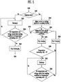
- FIG. 4 is a flowchart illustrating a control method of the protection apparatus according to an embodiment of the present invention.
- the measurement unit 123 measures voltages and temperatures of the secondary battery 110 according to predetermined periods (S100).
- the measurement unit 123 decides whether or not the measured voltages and temperatures satisfy a first swelling condition (S200). In the case where the measured voltages and temperatures satisfy the first swelling condition, the temperature estimation unit 125 estimates a temperature after a predetermined time (at a future time) using the temperatures measured in the measurement unit 123 (S300).
- the measurement unit 123 may measure temperatures and voltages of the secondary battery 110 by increasing the measurement frequency. To perform exact temperature estimation, the measurement unit 123 may compute temperature and voltage averages that are averages of temperatures and voltage measured for times set differently from each other.
- the charging/discharging control unit 127 decides whether or not the estimated temperature and the voltage average satisfy a second swelling condition (S400). In the case where the estimated temperature and the voltage average satisfy the second swelling condition, the charging/discharging control unit 127 controls charging/discharging of the secondary battery 110 (S500).
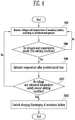
- FIG. 5 is a flowchart illustrating an operation of the charging/discharging control unit according to an embodiment of the present invention.
- the charging/discharging control unit 127 decides whether the secondary battery 110 is in a charging mode or in a non-charging mode (S510).
- the charging/discharging control unit 127 forcibly discharges the secondary battery 110, so that it is possible to prevent, in advance, the swelling phenomenon from occurring in the secondary battery 110 (S520).
- the charging/discharging control unit 127 may stop the forcible discharging of the secondary battery 110 (S540). If not, the forcible discharge continues (step S520).
- the charging/discharging control unit 127 control the temperatures and voltages of the secondary battery 110 to maintain the first swelling condition by adjusting current and voltage applied to the secondary battery 110 (S550).
- the charging/discharging control unit 127 decides whether or not the temperatures and voltages of the secondary battery 110 satisfy the second swelling condition (S560). In the case where the temperatures and voltages of the secondary battery 110 satisfy the second swelling condition even though the current or voltage applied to the secondary battery 110 is adjusted, the charging/discharging control unit 127 stops the charging of the secondary battery 110 (S570). Otherwise, the charging/discharging control unit 127 returns to the monitoring state, carrying out voltage and temperature measurements (S100).
- the charging/discharging control unit 127 forcibly discharges the secondary battery 110 (S593), so that it is possible to prevent the swelling phenomenon from occurring in the secondary battery 110. Forcible discharge continues until the temperature and voltage satisfy the first swelling condition or the rate of temperature increase falls below zero, ie. temperature starts to decrease (S595). At that point, forcible discharge is stopped and the battery can return to the charging condition (S590).
- the protection apparatus 120 estimates in advance a risk that the swelling phenomenon may occur in the secondary battery 110, and controls the charging/discharging of the secondary battery 110 when the risk exists, so that it is possible to prevent, in advance, the swelling phenomenon from occurring in the secondary battery 110.
- a preliminary swelling condition (first swelling condition) may be implemented in which measurement frequency is increased as compared to when the battery is operating normally and no swelling is expected, so as to more closely monitor the state of the battery as the risk of swelling increases.
Landscapes
- Engineering & Computer Science (AREA)
- Manufacturing & Machinery (AREA)
- Chemical & Material Sciences (AREA)
- Chemical Kinetics & Catalysis (AREA)
- Electrochemistry (AREA)
- General Chemical & Material Sciences (AREA)
- Power Engineering (AREA)
- Physics & Mathematics (AREA)
- General Physics & Mathematics (AREA)
- Secondary Cells (AREA)
- Charge And Discharge Circuits For Batteries Or The Like (AREA)
Description
- The present invention relates to a protection apparatus for a secondary battery, and more particularly, to a protection circuit for a secondary battery, which can prevent a swelling phenomenon from occurring in the secondary battery.
- Recently, secondary batteries have been used as power sources of portable electronic devices in many fields, and accordingly, demands on secondary batteries rapidly increase. The secondary batteries can be charged and discharged several times and thus are economically and environmentally effective. Accordingly, the use of the secondary batteries is promoted.
- A swelling phenomenon in which a secondary battery swells at a high temperature/high voltage due to gas or the like may occur in the secondary battery. The swelling phenomenon may cause an electrical short circuit. If an external impact is applied to the secondary battery in the state in which the secondary battery swells, a spark or the like occurs, and therefore, the secondary battery may explode.
- Conventionally, the swelling phenomenon was overcome in such a manner that an extra space was provided in a battery pack having a secondary battery mounted therein so that a user could not perceive the occurrence of a swelling phenomenon of the secondary battery. However, this manner does not meet the tendency of mobile products that gradually get slimmer, and there is a limitation that this manner does not provide a fundamental solution to the swelling phenomenon.
-
EP0593770 discloses a method and apparatus for charging a nickel-cadmium battery. The temperature and voltage of the battery are monitored. At the time when the temperature-rise rate of the battery is at least twice the increase of the one measured just before, or when the time of such a phenomenon being observed coincides with the time when the sensed voltage-rise rate of the battery lowers firstly after it increases continuously for a predetermined term, the operation of charging the battery is interrupted. - Embodiments provide a protection apparatus for a secondary battery, in which the charging/discharging of the secondary battery is controlled by estimating in advance a risk that a swelling phenomenon may occur in the secondary battery, so that it is possible to take appropriate action before swelling occurs and to prevent the swelling phenomenon from occurring in the secondary battery.
- According to an aspect of the present invention, there is provided protection apparatus for a secondary battery as set out in claim 1.
- When the measured voltage and estimated temperature satisfy the second swelling condition and the secondary battery is in a non-charging mode, the charging/discharging control means may be arranged to discharge the secondary battery.
- During the discharge of the secondary battery the apparatus may be arranged to determine if the measured voltage and estimated temperature satisfy the first swelling condition or if the temperature is decreasing, and in either case to stop discharge.
- When the measured voltage and estimated temperature satisfy the second swelling condition and the secondary battery is in a charging mode, the charging/discharging control means may be arranged to adjust the current and/or voltage applied to the secondary battery.
- The charging/discharging control means may be arranged to stop charging the secondary battery if the estimated temperature and measured voltage continue to satisfy the second swelling condition after adjusting the current and/or voltage applied to the secondary battery.
- The charging/discharging control means may be arranged to discharge the secondary battery if after stopping charging the secondary battery the temperature increases. The means for estimating the battery temperature may be arranged to estimate the battery temperature by using a rate of temperature change based on previously measured temperatures.
- The means for estimating the battery temperature may be arranged to weight rates of temperature change so that higher rates of temperature increase have a greater weight.
- The temperatures and voltages may comprise temperature and voltage averages measured over predetermined periods.
- The swelling condition may comprise a plurality of sets of temperature and allowable voltage values, the allowable voltage values decreasing with increasing temperature.
- The measuring means may be arranged to measure temperature and voltage of the secondary battery less frequently when the secondary battery is in a non-charging mode than when the secondary battery is in a charging mode.
- A secondary battery may comprise a battery cell and protection apparatus as described above connected to the battery cell.
- According to the present invention, it is possible to prevent, in advance, a swelling phenomenon from occurring in a secondary battery by estimating in advance a risk that the swelling phenomenon will occur in the secondary battery and controlling charging/discharging of the secondary battery when the risk exists.
- The accompanying drawings illustrate exemplary embodiments of the present invention, and, together with the description, serve to explain the principles of the present invention.
-
FIG. 1 is a block diagram schematically showing a protection apparatus for a secondary battery according to an embodiment of the present invention; -
FIG. 2 is a block diagram showing a detailed configuration of the protection apparatus according to the embodiment of the present invention; -
FIG. 3 is a graph illustrating a swelling condition and an operation of a charging/discharging control unit according to the swelling condition; -
FIG. 4 is a flowchart illustrating a control method of the protection apparatus according to an embodiment of the present invention; and -
FIG. 5 is a flowchart illustrating an operation of the charging/discharging control unit according to an embodiment of the present invention. - Referring to
FIG. 1 , theprotection apparatus 120 is coupled to asecondary battery 110 so as to control charging/discharging of thesecondary battery 110. - Here, an
external power source 100 refers to a power source that charges thesecondary battery 110 by applying current to thesecondary battery 110. For example, theexternal power source 100 may be an AC adapter coupled to a charging device of thesecondary battery 110 so as to apply current to thesecondary battery 110, but the present invention is not limited thereto. That is, theexternal power source 100 may include all power sources that can apply current to thesecondary battery 110. - The
secondary battery 110 refers to a rechargeable battery. Thesecondary battery 110 may include a lead-acid battery, a nickel cadmium (NiCd) battery, a nickel metal hydride (NiMH) battery, a lithium ion battery (LiB), a lithium polymer battery (LiPB), and the like. - The swelling phenomenon that occurs in the
secondary battery 110 is an irreversible phenomenon. Therefore, to maintain stable performance of thesecondary battery 110, it is important to prevent the swelling phenomenon from occurring in thesecondary battery 110. - The
protection apparatus 120 according to the present invention estimates a risk that the swelling phenomenon will occur in thesecondary battery 110 by monitoring the temperature and voltage of thesecondary battery 110, and controls the charging/discharging of thesecondary battery 110, so that it is possible to prevent, in advance, the swelling phenomenon of thesecondary battery 110. - According to an embodiment of the present invention, the
protection apparatus 120 may be coupled to thesecondary battery 110 so as to form a battery pack, or may be provided to an electronic device or charging device to which thesecondary battery 110 is coupled so as to protect thesecondary battery 110. - Hereinafter, the driving principle of the
protection apparatus 120 will be described in detail with reference toFIG. 2 . - Referring to
FIG. 2 , theprotection apparatus 120 may include amemory unit 121, ameasurement unit 123, atemperature estimation unit 125, a charging/discharging control unit 127 and acontrol unit 129. - The
memory unit 121 stores first and second swelling conditions of temperatures and voltages. - The first swelling condition refers to conditions in which there is a high risk that the swelling phenomenon will occur, and the second swelling condition refers to conditions in which the swelling phenomenon will almost inevitably occur. For example, the first and second swelling conditions may be stored in the
memory unit 121 as shown in the following Tables 1 and 2.Table 1 • First swelling condition Temperature (T) 40≤T<45 45≤T<50 50≤T<55 55≤T<60 60≤T Voltage (V) 4.1<V≤4.2 4.0<V≤4.1 3.9<V≤4.0 3.8<V≤3.9 3.7<V≤3.8 Table 2 • Second swelling condition Temperature (T) 40≤T<45 45≤T<50 50≤T<55 55≤T<60 60≤T Voltage (V) 4.2<V 4.1<V 4.0<V 3.9<V 3.8<V - Generally, as the temperature of the secondary battery 10 increases, the allowable voltage of the
secondary battery 110 decreases. Therefore, as the temperature of thesecondary battery 110 increases under the first and second swelling conditions, the allowable voltage of thesecondary battery 110 decreases. - According to Tables 1 and 2, in a case where the temperature of the
secondary battery 110 is 47 degrees and the voltage of thesecondary battery 110 is 4.05V, the first swelling condition is satisfied. In a case where the temperature of thesecondary battery 110 is 47 degrees and the voltage of thesecondary battery 110 is 4.2V, the second swelling condition is satisfied. - It will be apparent to those skilled in the art that the first and second swelling conditions are merely examples for illustrating the present invention, and may be variously set by a user according to the kind of the
secondary battery 110, the charging capacity of thesecondary battery 110, the charging environment of thesecondary battery 110, and the like. In other words, the swelling conditions are not limited to particular voltage and temperature combinations, but may include other parameters that indicate a risk of swelling occurring. Furthermore, the specific values given in the tables above are illustrative only. The first and second swelling conditions will be described in detail with reference to the accompanying drawings. - The
measurement unit 123 measures temperatures and voltages of thesecondary battery 110 according to predetermined measurement periods and measurement frequency. For example, in the case where theprotection apparatus 120 operates in a non-charging mode, themeasurement unit 123 may measure temperatures and voltages of thesecondary battery 110 less frequently than in the case where theprotection apparatus 120 operates in a charging mode, since the risk of swelling is greater in the charging mode than in the non-charging mode. - According to an embodiment of the present invention, in the case where the measured temperatures and voltages of the
secondary battery 110 satisfy the first swelling condition, themeasurement unit 123 may measure the temperatures and voltages of thesecondary battery 110 by increasing the measurement frequency. Generally, the swelling phenomenon tends to rapidly occur in thesecondary battery 110 according to the temperature and charging state of thesecondary battery 110. Thus, in a case where the measured temperatures and voltages of thesecondary battery 110 satisfy the first swelling condition, themeasurement unit 123 measures temperatures and voltages of thesecondary battery 110 more frequently, so that it is possible to rapidly prevent the swelling phenomenon from occurring in thesecondary battery 110. For example, if each measurement is made during a measurement time, the interval between measurement times is decreased so that more measurements are made in any given time period. - According to an embodiment of the present invention, the
measurement unit 123 may compute a temperature average and a voltage average using temperatures and voltages measured during predetermined times and store the temperature and voltage averages in thememory unit 121. - For example, the
measurement unit 123 may compute a temperature average of temperatures measured for 1 minute and a voltage average of voltages measured for 2 seconds, and store the temperature and voltage averages in thememory unit 121. In a case where the measurement period is 250msec, the temperature average means an average of temperatures measured 240 times, and the voltage average means an average of voltages measured eight times. That is, the voltage and temperature averages computed in themeasurement unit 123 may be renewed every two seconds and every one minute, respectively. Then, the renewed voltage and temperature averages may be stored in thememory unit 121. To perform temperature estimation, a predetermined number of past temperature averages may be stored together with the renewed temperature average in thememory unit 121. Since temperature changes relatively slowly while voltage changes more rapidly, the temperature average may be measured over a longer period for reliability, while the voltage average is measured over a relatively short period to capture rapid changes in voltage. - The temperature and voltage averages are used in the temperature estimation and control of the charging/discharging of the
secondary battery 110. Exceptionally measured temperatures and voltages, i.e. outlying data, are removed. Accordingly, more exact temperature estimation can be performed. - Hereinafter, for convenience of illustration, it will be described that the temperature and voltage measured in the
measurement unit 123 are a temperature average of temperatures, renewed every predetermined period, and a voltage average of voltages, renewed every predetermined period, respectively. However, the present invention is not limited thereto. - In the case where the temperatures and voltages measured in the
measurement unit 123 satisfy the first swelling condition, thetemperature estimation unit 125 estimates a temperature after a predetermined time, in other words at a future time, using temperatures measured in themeasurement unit 123. - More specifically, the
temperature estimation unit 125 may estimate the temperature after the predetermined time by using the temperature increasing rate computed using a temperature average before the predetermined time and a recently renewed temperature average. The temperature increasing rate and the estimated temperature after the predetermined time may be represented by the following Formula 1.

- For example, in the case where the temperature average measured over a 10 minute interval rises from 42 degrees to 47 degrees, then the temperature increasing rate, or rate of change of temperature, is 0.5 degrees per minute. If the current temperature is 48 degrees, then the estimated temperature after a further 10 minutes can be calculated as 48 + (0.5 x 10) =53 degrees.
- According to an embodiment of the present invention, the
temperature estimation unit 125 may estimate a temperature after a predetermined time using a weight according to the temperature increasing rate. That is, since the swelling phenomenon rapidly occurs in thesecondary battery 110, the probability that the swelling phenomenon will occur in thesecondary battery 110 increases as the temperature increasing rate increases. Therefore, to reflect this fact, the estimated temperature may be increased by increasing the weight as the temperature increasing rate increases. In this case, the estimated temperature may be represented by the following Formula 2.
- For example, in a case where the weight is 1.1 when the temperature increasing rate is 1 degree per unit time, the weight is 1.5 when the temperature increasing rate is 4 degrees per unit time, and the current temperature is 40 degrees, the estimated temperatures per unit time become (1.1×1)+40=41 degrees and (4×1.5)+40=46 degrees, respectively. That is, as the temperature increasing rate increases, the temperature estimated in the
temperature estimation unit 125 increases, and accordingly, the probability that the estimated temperature and the voltage average will satisfy the second swelling condition increases. - In the case where the estimated temperature and the voltage average satisfy the second swelling condition, the charging/discharging
control unit 127 prevents the swelling phenomenon from occurring in thesecondary battery 110 by controlling the charging/discharging of thesecondary battery 110. -
FIG. 3 is a graph illustrating a swelling condition and an operation of the charging/discharging control unit according to the swelling condition. - Referring to
FIG. 3 , regions A, B and C refer to a normal region where the battery is operating within normal parameters and swelling is not expected, a swelling preliminary region where swelling becomes a risk and a swelling region in which swelling will almost inevitably occur, respectively. That is, the region that satisfies the first swelling condition is shown as the region B, and the region that satisfies the second swelling condition is shown as the region C. - Therefore, in the case where the temperatures and voltages measured in the
measurement unit 123 exist in the region B, theprotection apparatus 120 decides that there is a risk that the swelling phenomenon may occur in thesecondary battery 110, and estimates a temperature after a predetermined time through thetemperature estimation unit 125. In the case where the estimated temperature and the voltage average renewed every predetermined time is out of the region B and exists in the region C, the charging/dischargingcontrol unit 127 controls the charging/discharging of thesecondary battery 110 so as to prevent the swelling phenomenon from occurring in thesecondary battery 110, in other words to prevent the conditions within the battery actually falling within region C. - According to an embodiment of the present invention, in the case where the
secondary battery 110 is in a non-charging mode, the charging/dischargingcontrol unit 127 may control the temperature and voltage of thesecondary battery 110 to maintain the first swelling condition or move the battery out of the first swelling condition into the normal operating condition by forcibly discharging thesecondary battery 110 and thus decreasing the voltage of thesecondary battery 110. In the case where the temperature and voltage of thesecondary battery 110 exist in the region A according to the discharging of thesecondary battery 110, the charging/dischargingcontrol unit 127 may stop the discharging of thesecondary battery 110. - According to an embodiment of the present invention, in the case where the
secondary battery 110 is in a charging mode, the charging/dischargingcontrol unit 127 may control the temperature and voltage of thesecondary battery 110 to maintain the first swelling condition or move the battery out of the first swelling condition into the normal operating condition by adjusting the current or voltage applied to thesecondary battery 110. In the case where the temperature and voltage of thesecondary battery 110 satisfy the second swelling condition even though the current or voltage applied to thesecondary battery 110 is adjusted, the charging/dischargingcontrol unit 127 may stop the charging of thesecondary battery 110 by cutting off the current or voltage applied to thesecondary battery 110. - In the case where the temperature increasing rate exceeds zero, after the charging of the
secondary battery 110 is stopped, the charging/dischargingcontrol unit 127 may forcibly discharge thesecondary battery 110. Subsequently, in the case where the temperature and voltage of thesecondary battery 110 satisfy the first swelling condition or the temperature increasing rate is less than zero, after the discharging of thesecondary battery 110, the charging/dischargingcontrol unit 127 may stop the discharging of thesecondary battery 110. - According to an embodiment of the present invention, in the case where the temperatures and voltages measured in the
measurement unit 123 have already satisfied the second swelling condition, the charging/dischargingcontrol unit 127 may immediately stop the charging of thesecondary battery 110 and control thesecondary battery 110 to be forcibly discharged. - The
control unit 129 may generally control thememory unit 121, themeasurement unit 123, thetemperature estimation unit 125 and the charging/dischargingcontrol unit 127. -
FIG. 4 is a flowchart illustrating a control method of the protection apparatus according to an embodiment of the present invention. - First, the
measurement unit 123 measures voltages and temperatures of thesecondary battery 110 according to predetermined periods (S100). - The
measurement unit 123 decides whether or not the measured voltages and temperatures satisfy a first swelling condition (S200). In the case where the measured voltages and temperatures satisfy the first swelling condition, thetemperature estimation unit 125 estimates a temperature after a predetermined time (at a future time) using the temperatures measured in the measurement unit 123 (S300). - In a case where the measured voltages and temperatures satisfy the first swelling condition, the
measurement unit 123 may measure temperatures and voltages of thesecondary battery 110 by increasing the measurement frequency. To perform exact temperature estimation, themeasurement unit 123 may compute temperature and voltage averages that are averages of temperatures and voltage measured for times set differently from each other. - The charging/discharging
control unit 127 decides whether or not the estimated temperature and the voltage average satisfy a second swelling condition (S400). In the case where the estimated temperature and the voltage average satisfy the second swelling condition, the charging/dischargingcontrol unit 127 controls charging/discharging of the secondary battery 110 (S500). -
FIG. 5 is a flowchart illustrating an operation of the charging/discharging control unit according to an embodiment of the present invention. - Referring to
FIG. 5 , the charging/dischargingcontrol unit 127 decides whether thesecondary battery 110 is in a charging mode or in a non-charging mode (S510). - In the case where the
secondary battery 110 is in the non-charging mode, the charging/dischargingcontrol unit 127 forcibly discharges thesecondary battery 110, so that it is possible to prevent, in advance, the swelling phenomenon from occurring in the secondary battery 110 (S520). - Subsequently, in the case where the temperatures and voltages of the
secondary battery 110 satisfy the first swelling condition, or the temperature increasing rate is less than zero (S530), the charging/dischargingcontrol unit 127 may stop the forcible discharging of the secondary battery 110 (S540). If not, the forcible discharge continues (step S520). - In the case where the
secondary battery 110 is in the charging mode (S510), the charging/dischargingcontrol unit 127 control the temperatures and voltages of thesecondary battery 110 to maintain the first swelling condition by adjusting current and voltage applied to the secondary battery 110 (S550). - The charging/discharging
control unit 127 decides whether or not the temperatures and voltages of thesecondary battery 110 satisfy the second swelling condition (S560). In the case where the temperatures and voltages of thesecondary battery 110 satisfy the second swelling condition even though the current or voltage applied to thesecondary battery 110 is adjusted, the charging/dischargingcontrol unit 127 stops the charging of the secondary battery 110 (S570). Otherwise, the charging/dischargingcontrol unit 127 returns to the monitoring state, carrying out voltage and temperature measurements (S100). - In the case where the temperature increasing rate of the
secondary battery 110 exceeds zero even though the charging of thesecondary battery 110 is stopped (S580), the charging/dischargingcontrol unit 127 forcibly discharges the secondary battery 110 (S593), so that it is possible to prevent the swelling phenomenon from occurring in thesecondary battery 110. Forcible discharge continues until the temperature and voltage satisfy the first swelling condition or the rate of temperature increase falls below zero, ie. temperature starts to decrease (S595). At that point, forcible discharge is stopped and the battery can return to the charging condition (S590). - As described above, the
protection apparatus 120 according to the present invention estimates in advance a risk that the swelling phenomenon may occur in thesecondary battery 110, and controls the charging/discharging of thesecondary battery 110 when the risk exists, so that it is possible to prevent, in advance, the swelling phenomenon from occurring in thesecondary battery 110. A preliminary swelling condition (first swelling condition) may be implemented in which measurement frequency is increased as compared to when the battery is operating normally and no swelling is expected, so as to more closely monitor the state of the battery as the risk of swelling increases. - While the present invention has been described in connection with certain exemplary embodiments, it is to be understood that the invention is not limited to the disclosed embodiments, but, on the contrary, is intended to cover various modifications and equivalent arrangements included within the scope of the appended claims.
Claims (12)
- Protection apparatus (120) for a secondary battery (120), comprising:means (121) configured to store temperature and voltage information defining a swelling condition of a secondary battery (120);means (123) configured to measure temperature and voltage of the secondary battery (120);means (125) configured to estimate the battery temperature at a predetermined time based on the measured temperature; andmeans (127) configured to control charging/discharging of the secondary battery (120) when the estimated temperature and the measured voltage satisfy the swelling condition;the protection apparatus being characterised in that the stored temperature and voltage define first and second swelling conditions, in that the estimating means (125) is arranged to start estimating the battery temperature when the first swelling condition is satisfied and the means (127) for controlling charging/discharging is arranged to operate when the estimated temperature and the measured voltage satisfy the second swelling condition;and in that the measuring means (123) is arranged to measure temperature and voltage of the secondary battery (120) in a normal state at a first frequency and to measure temperature and voltage of the secondary battery (120) at a second frequency higher than the first frequency when the measured temperature and voltage satisfy the first swelling condition.
- Apparatus according to claim 1, wherein when the measured voltage and estimated temperature satisfy the second swelling condition and the secondary battery is in a non-charging mode, the charging/discharging control means is arranged to discharge the secondary battery.
- Apparatus according to claim 2, wherein during the discharge of the secondary battery (120) the apparatus is arranged to determine if the measured voltage and estimated temperature satisfy the first swelling condition or if the temperature is decreasing, and in either case to stop discharge.
- Apparatus according to claim 1, wherein when the measured voltage and estimated temperature satisfy the second swelling condition and the secondary battery (120) is in a charging mode, the charging/discharging control means (127) is arranged to adjust the current and/or voltage applied to the secondary battery (120).
- Apparatus according to claim 4, wherein the charging/discharging control means (127) is arranged to stop charging the secondary battery (120) if the estimated temperature and measured voltage continue to satisfy the second swelling condition after adjusting the current and/or voltage applied to the secondary battery (120).
- Apparatus according to claim 5, wherein the charging/discharging control means (127) is arranged to discharge the secondary battery (120) if after stopping charging the secondary battery (120) the temperature increases.
- Apparatus according to any one of the preceding claims, wherein the means (125) configured to estimate the battery temperature is arranged to estimate the battery temperature by using a rate of temperature change based on previously measured temperatures.
- Apparatus according to claim 7, wherein the means (125) configured to estimate the battery temperature is arranged to weight rates of temperature change so that higher rates of temperature increase have a greater weight.
- Apparatus according to any one of the preceding claims, wherein the temperatures and voltages comprise temperature and voltage averages measured over predetermined periods.
- Apparatus according to any one of the preceding claims, wherein the swelling condition comprises a plurality of sets of temperature and allowable voltage values, the allowable voltage values decreasing with increasing temperature.
- Apparatus according to any one of the preceding claims, wherein the measuring means (123) is arranged to measure temperature and voltage of the secondary battery (120) less frequently when the secondary battery (120) is in a non-charging mode than when the secondary battery (120) is in a charging mode.
- A secondary battery comprising a battery cell and apparatus according to any one of the preceding claims connected to the battery cell.
Applications Claiming Priority (2)
| Application Number | Priority Date | Filing Date | Title |
|---|---|---|---|
| US201261704980P | 2012-09-24 | 2012-09-24 | |
| US13/957,388 US9252623B2 (en) | 2012-09-24 | 2013-08-01 | Protection apparatus for secondary battery |
Publications (2)
| Publication Number | Publication Date |
|---|---|
| EP2712018A1 EP2712018A1 (en) | 2014-03-26 |
| EP2712018B1 true EP2712018B1 (en) | 2018-01-10 |
Family
ID=48914176
Family Applications (1)
| Application Number | Title | Priority Date | Filing Date |
|---|---|---|---|
| EP13179455.4A Active EP2712018B1 (en) | 2012-09-24 | 2013-08-06 | Protection apparatus for secondary battery |
Country Status (4)
| Country | Link |
|---|---|
| US (1) | US9252623B2 (en) |
| EP (1) | EP2712018B1 (en) |
| KR (1) | KR102119154B1 (en) |
| CN (1) | CN103682507B (en) |
Families Citing this family (24)
| Publication number | Priority date | Publication date | Assignee | Title |
|---|---|---|---|---|
| US9457682B2 (en) * | 2013-08-30 | 2016-10-04 | GM Global Technology Operations LLC | Method for predicting charging process duration |
| KR20160027847A (en) | 2014-09-02 | 2016-03-10 | 삼성전자주식회사 | Electronic device and method for charging controlling of the electronic device |
| KR101685130B1 (en) * | 2014-12-19 | 2016-12-09 | 주식회사 엘지화학 | Apparatus and Method for controlling power for secondary battery |
| DE102015001069A1 (en) * | 2015-01-29 | 2016-08-04 | Man Truck & Bus Ag | Method and device for temperature-dependent current limitation of an energy storage device for electrical energy |
| ES2770655T3 (en) * | 2015-03-27 | 2020-07-02 | Guangdong Oppo Mobile Telecommunications Corp Ltd | Electric power management procedure and apparatus and electronic device |
| CN105993107A (en) * | 2015-03-27 | 2016-10-05 | 广东欧珀移动通信有限公司 | Method, device and power adapter for controlling charging |
| KR102352449B1 (en) | 2015-04-30 | 2022-01-18 | 삼성전자주식회사 | Method for preventing battery swelling and electronic device thereof |
| CN105137316B (en) * | 2015-06-04 | 2018-05-22 | 科力远混合动力技术有限公司 | A kind of monitoring method of deterioration of battery |
| US10587135B2 (en) * | 2015-09-11 | 2020-03-10 | Microsoft Technology Licensing, Llc | Adaptive battery charging |
| JP6623306B2 (en) * | 2015-11-16 | 2019-12-18 | モレックス エルエルシー | Power charging module and method of using the same |
| KR102633756B1 (en) * | 2016-04-28 | 2024-02-05 | 삼성에스디아이 주식회사 | battery pack and battery pack charging method |
| JP6863795B2 (en) * | 2017-03-30 | 2021-04-21 | ビークルエナジージャパン株式会社 | Battery energy storage system, battery management system and control method |
| JP6864536B2 (en) * | 2017-04-25 | 2021-04-28 | 株式会社東芝 | Rechargeable battery system, charging method, program, and vehicle |
| EP3664205A4 (en) * | 2017-07-31 | 2020-08-19 | Nissan Motor Co., Ltd. | POWER SUPPLY SYSTEM AND CONTROL PROCEDURES FOR IT |
| JP6982445B2 (en) | 2017-09-20 | 2021-12-17 | 株式会社東芝 | Battery evaluation device, battery control device, battery evaluation method, battery evaluation program, control circuit and power storage system. |
| CN107591858B (en) * | 2017-09-21 | 2020-10-27 | 邳州市润宏实业有限公司 | Charging method, terminal and computer readable storage medium |
| CN108011135A (en) * | 2017-11-24 | 2018-05-08 | 深圳伊讯科技有限公司 | A kind of cell expansion measuring method and system |
| JP7000845B2 (en) * | 2017-12-25 | 2022-01-19 | トヨタ自動車株式会社 | Nickel-metal hydride battery regeneration device and regeneration method |
| JP7062180B2 (en) * | 2019-01-18 | 2022-05-06 | エルジー エナジー ソリューション リミテッド | Battery management device and method |
| CA3136483A1 (en) * | 2019-04-08 | 2020-10-15 | Aclara Technologies Llc | Determining battery life based on temperature and voltage |
| KR102949544B1 (en) * | 2020-07-14 | 2026-04-06 | 주식회사 엘지에너지솔루션 | Battery Pack with improved accuracy of swelling measurement |
| KR20220045450A (en) * | 2020-10-05 | 2022-04-12 | 주식회사 엘지에너지솔루션 | Apparatus for Managing Swelling of Secondary Battery and Method of Controlling the Same |
| DE102021000081A1 (en) | 2021-01-04 | 2022-07-07 | Otto-von-Guericke-Universität Magdeburg, Körperschaft des öffentlichen Rechts | Method for monitoring an electrical energy store and electrical energy store |
| TWI811111B (en) * | 2022-09-20 | 2023-08-01 | 順達科技股份有限公司 | Method of battery cell voltage dynamic regulation |
Family Cites Families (10)
| Publication number | Priority date | Publication date | Assignee | Title |
|---|---|---|---|---|
| WO1993019496A1 (en) | 1992-03-16 | 1993-09-30 | 4C Technologies Inc. | Quick charger and quick charge method for nickel-cadmium battery |
| KR100296619B1 (en) | 1998-12-18 | 2001-10-26 | 서평원 | How to charge your device |
| WO2005069408A1 (en) * | 2004-01-20 | 2005-07-28 | Matsushita Electric Industrial Co., Ltd. | Battery pack |
| JP4662530B2 (en) * | 2004-01-20 | 2011-03-30 | パナソニック株式会社 | Battery pack |
| JP2006304572A (en) * | 2005-04-25 | 2006-11-02 | Matsushita Electric Works Ltd | Charging device |
| KR101042768B1 (en) | 2008-06-03 | 2011-06-20 | 삼성에스디아이 주식회사 | Battery pack and its charging method |
| KR101093928B1 (en) | 2009-11-26 | 2011-12-13 | 삼성에스디아이 주식회사 | Battery packs and methods for preventing high temperature swelling of battery cells |
| US8854009B2 (en) * | 2010-06-17 | 2014-10-07 | Sony Corporation | Mobile terminal, method of protecting battery, and battery protection program |
| US20130082664A1 (en) * | 2010-06-25 | 2013-04-04 | Tatsuki HIRAOKA | Charging method and charging system for lithium ion secondary battery |
| US20120256752A1 (en) * | 2011-04-06 | 2012-10-11 | James William Musser | System and method to extend operating life of rechargable batteries using battery charge management |
-
2013
- 2013-08-01 US US13/957,388 patent/US9252623B2/en active Active
- 2013-08-06 EP EP13179455.4A patent/EP2712018B1/en active Active
- 2013-09-23 KR KR1020130112552A patent/KR102119154B1/en active Active
- 2013-09-24 CN CN201310439557.0A patent/CN103682507B/en active Active
Non-Patent Citations (1)
| Title |
|---|
| None * |
Also Published As
| Publication number | Publication date |
|---|---|
| US9252623B2 (en) | 2016-02-02 |
| US20140084873A1 (en) | 2014-03-27 |
| CN103682507A (en) | 2014-03-26 |
| KR20140040027A (en) | 2014-04-02 |
| KR102119154B1 (en) | 2020-06-04 |
| EP2712018A1 (en) | 2014-03-26 |
| CN103682507B (en) | 2018-01-02 |
Similar Documents
| Publication | Publication Date | Title |
|---|---|---|
| EP2712018A1 (en) | Protection apparatus for secondary battery | |
| EP3890097B1 (en) | Charging method and device | |
| EP2838176B1 (en) | Method for charging secondary battery | |
| JP4591560B2 (en) | Battery pack and control method | |
| EP1064690B1 (en) | Method enhancing smart battery performance | |
| US20190222051A1 (en) | Methods and systems for recharging a battery | |
| US10873201B2 (en) | Battery management apparatus and method for protecting a lithium iron phosphate cell from over-voltage using the same | |
| EP2613423B1 (en) | Power pack partial failure detection and remedial charging control | |
| US7135839B2 (en) | Battery pack and method of charging and discharging the same | |
| EP3141919B1 (en) | Apparatus and method for estimating open circuit voltage | |
| US11486932B2 (en) | Method for managing a state of charge of a battery left to rest | |
| US11418047B2 (en) | Battery charging method and system depending on ambient temperature | |
| JP4248854B2 (en) | Battery management system and battery pack | |
| JP2016178052A (en) | Control system of secondary cell | |
| JP7055810B2 (en) | How to prevent the swelling of the battery cell and the battery pack using it | |
| KR20180031206A (en) | Battery management system and method for protecting a battery from over-discharge | |
| KR20170142451A (en) | Battery management system, battery pack and method for charging battery | |
| JP2017156272A (en) | Deteriorated state estimating device for batteries, and deteriorated state estimating method for the device | |
| EP4236006A1 (en) | Method for charging power battery and battery management system | |
| US20240097460A1 (en) | Methods, Apparatuses, and Systems That Include Secondary Electrochemical Unit Anomaly Detection and/or Overcharge Prevention Based On Reverse Coulombic Efficiency | |
| KR101497549B1 (en) | Recovering method for charging capacity of battery and the charging device | |
| CN100592099C (en) | Apparatus and method for charging a battery | |
| KR101091387B1 (en) | Battery protection device and method through full charge capacity comparison | |
| EP4228118A1 (en) | Method for charging power battery and battery management system | |
| KR20140024157A (en) | Power supply control device for rechargeabel battery |
Legal Events
| Date | Code | Title | Description |
|---|---|---|---|
| PUAI | Public reference made under article 153(3) epc to a published international application that has entered the european phase |
Free format text: ORIGINAL CODE: 0009012 |
|
| AK | Designated contracting states |
Kind code of ref document: A1 Designated state(s): AL AT BE BG CH CY CZ DE DK EE ES FI FR GB GR HR HU IE IS IT LI LT LU LV MC MK MT NL NO PL PT RO RS SE SI SK SM TR |
|
| AX | Request for extension of the european patent |
Extension state: BA ME |
|
| 17P | Request for examination filed |
Effective date: 20140926 |
|
| RBV | Designated contracting states (corrected) |
Designated state(s): AL AT BE BG CH CY CZ DE DK EE ES FI FR GB GR HR HU IE IS IT LI LT LU LV MC MK MT NL NO PL PT RO RS SE SI SK SM TR |
|
| GRAP | Despatch of communication of intention to grant a patent |
Free format text: ORIGINAL CODE: EPIDOSNIGR1 |
|
| STAA | Information on the status of an ep patent application or granted ep patent |
Free format text: STATUS: GRANT OF PATENT IS INTENDED |
|
| RIC1 | Information provided on ipc code assigned before grant |
Ipc: H02J 7/00 20060101ALI20170629BHEP Ipc: H01M 10/44 20060101AFI20170629BHEP |
|
| INTG | Intention to grant announced |
Effective date: 20170721 |
|
| GRAS | Grant fee paid |
Free format text: ORIGINAL CODE: EPIDOSNIGR3 |
|
| GRAA | (expected) grant |
Free format text: ORIGINAL CODE: 0009210 |
|
| STAA | Information on the status of an ep patent application or granted ep patent |
Free format text: STATUS: THE PATENT HAS BEEN GRANTED |
|
| AK | Designated contracting states |
Kind code of ref document: B1 Designated state(s): AL AT BE BG CH CY CZ DE DK EE ES FI FR GB GR HR HU IE IS IT LI LT LU LV MC MK MT NL NO PL PT RO RS SE SI SK SM TR |
|
| RAP1 | Party data changed (applicant data changed or rights of an application transferred) |
Owner name: SAMSUNG SDI CO., LTD. |
|
| REG | Reference to a national code |
Ref country code: CH Ref legal event code: EP Ref country code: AT Ref legal event code: REF Ref document number: 963369 Country of ref document: AT Kind code of ref document: T Effective date: 20180115 |
|
| REG | Reference to a national code |
Ref country code: IE Ref legal event code: FG4D |
|
| REG | Reference to a national code |
Ref country code: DE Ref legal event code: R096 Ref document number: 602013031879 Country of ref document: DE |
|
| REG | Reference to a national code |
Ref country code: NL Ref legal event code: MP Effective date: 20180110 |
|
| REG | Reference to a national code |
Ref country code: AT Ref legal event code: MK05 Ref document number: 963369 Country of ref document: AT Kind code of ref document: T Effective date: 20180110 |
|
| PG25 | Lapsed in a contracting state [announced via postgrant information from national office to epo] |
Ref country code: NL Free format text: LAPSE BECAUSE OF FAILURE TO SUBMIT A TRANSLATION OF THE DESCRIPTION OR TO PAY THE FEE WITHIN THE PRESCRIBED TIME-LIMIT Effective date: 20180110 |
|
| REG | Reference to a national code |
Ref country code: FR Ref legal event code: PLFP Year of fee payment: 6 |
|
| PG25 | Lapsed in a contracting state [announced via postgrant information from national office to epo] |
Ref country code: LT Free format text: LAPSE BECAUSE OF FAILURE TO SUBMIT A TRANSLATION OF THE DESCRIPTION OR TO PAY THE FEE WITHIN THE PRESCRIBED TIME-LIMIT Effective date: 20180110 Ref country code: FI Free format text: LAPSE BECAUSE OF FAILURE TO SUBMIT A TRANSLATION OF THE DESCRIPTION OR TO PAY THE FEE WITHIN THE PRESCRIBED TIME-LIMIT Effective date: 20180110 Ref country code: CY Free format text: LAPSE BECAUSE OF FAILURE TO SUBMIT A TRANSLATION OF THE DESCRIPTION OR TO PAY THE FEE WITHIN THE PRESCRIBED TIME-LIMIT Effective date: 20180110 Ref country code: NO Free format text: LAPSE BECAUSE OF FAILURE TO SUBMIT A TRANSLATION OF THE DESCRIPTION OR TO PAY THE FEE WITHIN THE PRESCRIBED TIME-LIMIT Effective date: 20180410 Ref country code: ES Free format text: LAPSE BECAUSE OF FAILURE TO SUBMIT A TRANSLATION OF THE DESCRIPTION OR TO PAY THE FEE WITHIN THE PRESCRIBED TIME-LIMIT Effective date: 20180110 Ref country code: HR Free format text: LAPSE BECAUSE OF FAILURE TO SUBMIT A TRANSLATION OF THE DESCRIPTION OR TO PAY THE FEE WITHIN THE PRESCRIBED TIME-LIMIT Effective date: 20180110 |
|
| PG25 | Lapsed in a contracting state [announced via postgrant information from national office to epo] |
Ref country code: LV Free format text: LAPSE BECAUSE OF FAILURE TO SUBMIT A TRANSLATION OF THE DESCRIPTION OR TO PAY THE FEE WITHIN THE PRESCRIBED TIME-LIMIT Effective date: 20180110 Ref country code: SE Free format text: LAPSE BECAUSE OF FAILURE TO SUBMIT A TRANSLATION OF THE DESCRIPTION OR TO PAY THE FEE WITHIN THE PRESCRIBED TIME-LIMIT Effective date: 20180110 Ref country code: RS Free format text: LAPSE BECAUSE OF FAILURE TO SUBMIT A TRANSLATION OF THE DESCRIPTION OR TO PAY THE FEE WITHIN THE PRESCRIBED TIME-LIMIT Effective date: 20180110 Ref country code: AT Free format text: LAPSE BECAUSE OF FAILURE TO SUBMIT A TRANSLATION OF THE DESCRIPTION OR TO PAY THE FEE WITHIN THE PRESCRIBED TIME-LIMIT Effective date: 20180110 Ref country code: IS Free format text: LAPSE BECAUSE OF FAILURE TO SUBMIT A TRANSLATION OF THE DESCRIPTION OR TO PAY THE FEE WITHIN THE PRESCRIBED TIME-LIMIT Effective date: 20180510 Ref country code: BG Free format text: LAPSE BECAUSE OF FAILURE TO SUBMIT A TRANSLATION OF THE DESCRIPTION OR TO PAY THE FEE WITHIN THE PRESCRIBED TIME-LIMIT Effective date: 20180410 Ref country code: GR Free format text: LAPSE BECAUSE OF FAILURE TO SUBMIT A TRANSLATION OF THE DESCRIPTION OR TO PAY THE FEE WITHIN THE PRESCRIBED TIME-LIMIT Effective date: 20180411 Ref country code: PL Free format text: LAPSE BECAUSE OF FAILURE TO SUBMIT A TRANSLATION OF THE DESCRIPTION OR TO PAY THE FEE WITHIN THE PRESCRIBED TIME-LIMIT Effective date: 20180110 |
|
| REG | Reference to a national code |
Ref country code: DE Ref legal event code: R097 Ref document number: 602013031879 Country of ref document: DE |
|
| PG25 | Lapsed in a contracting state [announced via postgrant information from national office to epo] |
Ref country code: RO Free format text: LAPSE BECAUSE OF FAILURE TO SUBMIT A TRANSLATION OF THE DESCRIPTION OR TO PAY THE FEE WITHIN THE PRESCRIBED TIME-LIMIT Effective date: 20180110 Ref country code: EE Free format text: LAPSE BECAUSE OF FAILURE TO SUBMIT A TRANSLATION OF THE DESCRIPTION OR TO PAY THE FEE WITHIN THE PRESCRIBED TIME-LIMIT Effective date: 20180110 Ref country code: IT Free format text: LAPSE BECAUSE OF FAILURE TO SUBMIT A TRANSLATION OF THE DESCRIPTION OR TO PAY THE FEE WITHIN THE PRESCRIBED TIME-LIMIT Effective date: 20180110 Ref country code: AL Free format text: LAPSE BECAUSE OF FAILURE TO SUBMIT A TRANSLATION OF THE DESCRIPTION OR TO PAY THE FEE WITHIN THE PRESCRIBED TIME-LIMIT Effective date: 20180110 |
|
| PLBE | No opposition filed within time limit |
Free format text: ORIGINAL CODE: 0009261 |
|
| STAA | Information on the status of an ep patent application or granted ep patent |
Free format text: STATUS: NO OPPOSITION FILED WITHIN TIME LIMIT |
|
| PG25 | Lapsed in a contracting state [announced via postgrant information from national office to epo] |
Ref country code: SK Free format text: LAPSE BECAUSE OF FAILURE TO SUBMIT A TRANSLATION OF THE DESCRIPTION OR TO PAY THE FEE WITHIN THE PRESCRIBED TIME-LIMIT Effective date: 20180110 Ref country code: SM Free format text: LAPSE BECAUSE OF FAILURE TO SUBMIT A TRANSLATION OF THE DESCRIPTION OR TO PAY THE FEE WITHIN THE PRESCRIBED TIME-LIMIT Effective date: 20180110 Ref country code: DK Free format text: LAPSE BECAUSE OF FAILURE TO SUBMIT A TRANSLATION OF THE DESCRIPTION OR TO PAY THE FEE WITHIN THE PRESCRIBED TIME-LIMIT Effective date: 20180110 Ref country code: CZ Free format text: LAPSE BECAUSE OF FAILURE TO SUBMIT A TRANSLATION OF THE DESCRIPTION OR TO PAY THE FEE WITHIN THE PRESCRIBED TIME-LIMIT Effective date: 20180110 |
|
| 26N | No opposition filed |
Effective date: 20181011 |
|
| PG25 | Lapsed in a contracting state [announced via postgrant information from national office to epo] |
Ref country code: SI Free format text: LAPSE BECAUSE OF FAILURE TO SUBMIT A TRANSLATION OF THE DESCRIPTION OR TO PAY THE FEE WITHIN THE PRESCRIBED TIME-LIMIT Effective date: 20180110 |
|
| PG25 | Lapsed in a contracting state [announced via postgrant information from national office to epo] |
Ref country code: MC Free format text: LAPSE BECAUSE OF FAILURE TO SUBMIT A TRANSLATION OF THE DESCRIPTION OR TO PAY THE FEE WITHIN THE PRESCRIBED TIME-LIMIT Effective date: 20180110 |
|
| REG | Reference to a national code |
Ref country code: CH Ref legal event code: PL |
|
| PG25 | Lapsed in a contracting state [announced via postgrant information from national office to epo] |
Ref country code: LU Free format text: LAPSE BECAUSE OF NON-PAYMENT OF DUE FEES Effective date: 20180806 Ref country code: LI Free format text: LAPSE BECAUSE OF NON-PAYMENT OF DUE FEES Effective date: 20180831 Ref country code: CH Free format text: LAPSE BECAUSE OF NON-PAYMENT OF DUE FEES Effective date: 20180831 |
|
| REG | Reference to a national code |
Ref country code: BE Ref legal event code: MM Effective date: 20180831 |
|
| REG | Reference to a national code |
Ref country code: IE Ref legal event code: MM4A |
|
| PG25 | Lapsed in a contracting state [announced via postgrant information from national office to epo] |
Ref country code: IE Free format text: LAPSE BECAUSE OF NON-PAYMENT OF DUE FEES Effective date: 20180806 |
|
| PG25 | Lapsed in a contracting state [announced via postgrant information from national office to epo] |
Ref country code: BE Free format text: LAPSE BECAUSE OF NON-PAYMENT OF DUE FEES Effective date: 20180831 |
|
| PG25 | Lapsed in a contracting state [announced via postgrant information from national office to epo] |
Ref country code: MT Free format text: LAPSE BECAUSE OF NON-PAYMENT OF DUE FEES Effective date: 20180806 |
|
| PG25 | Lapsed in a contracting state [announced via postgrant information from national office to epo] |
Ref country code: TR Free format text: LAPSE BECAUSE OF FAILURE TO SUBMIT A TRANSLATION OF THE DESCRIPTION OR TO PAY THE FEE WITHIN THE PRESCRIBED TIME-LIMIT Effective date: 20180110 |
|
| PG25 | Lapsed in a contracting state [announced via postgrant information from national office to epo] |
Ref country code: HU Free format text: LAPSE BECAUSE OF FAILURE TO SUBMIT A TRANSLATION OF THE DESCRIPTION OR TO PAY THE FEE WITHIN THE PRESCRIBED TIME-LIMIT; INVALID AB INITIO Effective date: 20130806 Ref country code: PT Free format text: LAPSE BECAUSE OF FAILURE TO SUBMIT A TRANSLATION OF THE DESCRIPTION OR TO PAY THE FEE WITHIN THE PRESCRIBED TIME-LIMIT Effective date: 20180110 |
|
| PG25 | Lapsed in a contracting state [announced via postgrant information from national office to epo] |
Ref country code: MK Free format text: LAPSE BECAUSE OF NON-PAYMENT OF DUE FEES Effective date: 20180110 |
|
| P01 | Opt-out of the competence of the unified patent court (upc) registered |
Effective date: 20230528 |
|
| PGFP | Annual fee paid to national office [announced via postgrant information from national office to epo] |
Ref country code: DE Payment date: 20250805 Year of fee payment: 13 |
|
| PGFP | Annual fee paid to national office [announced via postgrant information from national office to epo] |
Ref country code: GB Payment date: 20250731 Year of fee payment: 13 |
|
| PGFP | Annual fee paid to national office [announced via postgrant information from national office to epo] |
Ref country code: FR Payment date: 20250808 Year of fee payment: 13 |