EP2711668A1 - Coaxial gyro accelerometer in a semiconductor substrate - Google Patents
Coaxial gyro accelerometer in a semiconductor substrate Download PDFInfo
- Publication number
- EP2711668A1 EP2711668A1 EP13175954.0A EP13175954A EP2711668A1 EP 2711668 A1 EP2711668 A1 EP 2711668A1 EP 13175954 A EP13175954 A EP 13175954A EP 2711668 A1 EP2711668 A1 EP 2711668A1
- Authority
- EP
- European Patent Office
- Prior art keywords
- cantilever beam
- resonating
- substrate
- gyro
- sensor
- Prior art date
- Legal status (The legal status is an assumption and is not a legal conclusion. Google has not performed a legal analysis and makes no representation as to the accuracy of the status listed.)
- Withdrawn
Links
Images
Classifications
-
- G—PHYSICS
- G01—MEASURING; TESTING
- G01C—MEASURING DISTANCES, LEVELS OR BEARINGS; SURVEYING; NAVIGATION; GYROSCOPIC INSTRUMENTS; PHOTOGRAMMETRY OR VIDEOGRAMMETRY
- G01C19/00—Gyroscopes; Turn-sensitive devices using vibrating masses; Turn-sensitive devices without moving masses; Measuring angular rate using gyroscopic effects
- G01C19/58—Turn-sensitive devices without moving masses
- G01C19/64—Gyrometers using the Sagnac effect, i.e. rotation-induced shifts between counter-rotating electromagnetic beams
- G01C19/72—Gyrometers using the Sagnac effect, i.e. rotation-induced shifts between counter-rotating electromagnetic beams with counter-rotating light beams in a passive ring, e.g. fibre laser gyrometers
- G01C19/721—Details
-
- G—PHYSICS
- G01—MEASURING; TESTING
- G01P—MEASURING LINEAR OR ANGULAR SPEED, ACCELERATION, DECELERATION, OR SHOCK; INDICATING PRESENCE, ABSENCE, OR DIRECTION, OF MOVEMENT
- G01P15/00—Measuring acceleration; Measuring deceleration; Measuring shock, i.e. sudden change of acceleration
- G01P15/02—Measuring acceleration; Measuring deceleration; Measuring shock, i.e. sudden change of acceleration by making use of inertia forces using solid seismic masses
- G01P15/08—Measuring acceleration; Measuring deceleration; Measuring shock, i.e. sudden change of acceleration by making use of inertia forces using solid seismic masses with conversion into electric or magnetic values
- G01P15/12—Measuring acceleration; Measuring deceleration; Measuring shock, i.e. sudden change of acceleration by making use of inertia forces using solid seismic masses with conversion into electric or magnetic values by alteration of electrical resistance
- G01P15/123—Measuring acceleration; Measuring deceleration; Measuring shock, i.e. sudden change of acceleration by making use of inertia forces using solid seismic masses with conversion into electric or magnetic values by alteration of electrical resistance by piezo-resistive elements, e.g. semiconductor strain gauges
Definitions
- a pendulating integrating gyroscopic accelerometer is a type of accelerometer that can measure acceleration and simultaneously integrate this acceleration against time to produce a speed measure, as well.
- the PIGA's main use is in inertial navigation systems (INS) for guidance of aircraft and most particularly for ballistic missile guidance. It is valued for its extremely high sensitivity and accuracy in conjunction with operation over a wide acceleration range.
- INS inertial navigation systems
- the PIGA is still considered the premier instrument for strategic-grade missile guidance, though systems based on MEMS technology are attractive for lower performance requirements.
- the PIGA has significant size and weight that make it non-optimum in many applications. Also, the PIGA is a mechanical mechanism requiring high-precision machining tolerances and, thus, is very expensive to manufacture.
- the present invention provides an integrated interferometric gyroscope and accelerometer device for simultaneously sensing coaxial linear and rotational forces.
- An exemplary device includes a resonating cantilever (RC) beam within a substrate, a sensor package having a cavity for the RC beam, a piezoresistor driver, a piezoresistor sensor, and a semiconductor interferometric optical gyro.
- the piezoresistor driver and sensor are incorporated within the RC beam.
- the driver electrothermally resonates the RC beam.
- the sensor piezoresitively senses a signal that relates to an acceleration force out-of-plane of the RC beam.
- a waveguide of the semiconductor interferometric optical gyro is incorporated in the substrate around the RC beam.
- the gyro senses rotational motion about the axis that is the same as the acceleration vector (out-of-plane of the RC beam).
- the gyro also includes a laser source and a light detector.
- the RC beam is formed from the semiconductor substrate.
- the gyro includes a spiraled waveguide that is coaxial with a center of gravity (CG) point of the corresponding RC beam. Each determined center point is the point at which the z-axis passes through the respective RC beam.
- CG center of gravity
- the semiconductor substrate is a single silicon substrate.
- the light source and light detector include a P-N junction formed within a layer of the substrate.
- the interferometric optical gyro further includes interface electronics formed in or on the substrate.
- the device includes a sensor package lid that is hermetically sealed with the sensor package.
- FIGURE 1 is a cross-sectional view of an exemplary device formed in accordance with an embodiment of the present invention
- FIGURE 2 is a top view of the device shown in FIGURE 1 ;
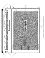
- FIGURE 3 is a cross-sectional view of an exemplary device formed in accordance with another embodiment of the present invention.
- FIGURE 4 is a top view of the device shown in FIGURE 3 ;
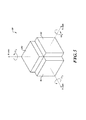
- FIGURE 5 is a perspective view of a three-axis gyro/accelerometer system formed in accordance with an embodiment of the present invention.
- the present invention is a gyro and accelerometer integrated into a single semiconductor substrate that is combinable into a three-axis gyroscope/accelerometer.
- the single semiconductor substrate has the ability to simultaneously sense linear and rotational forces.
- an exemplary integrated gyro accelerometer device 20 includes a semiconductor substrate layer 32 that includes a semiconductor interferometric fiber-optic gyro (IFOG) 26 and a cantilever strain-resistive beam 21.
- the cantilever strain-resistive beam 21 includes a resonating component 36.
- the cantilever strain-resistive beam 21 is driven electrothermally to resonate by means of an implanted piezoresistor driver 36-1. Change in beam resonance (i.e., acceleration along the z-axis) is sensed piezoresistively by an implanted piezoresistor sensor 36-2.
- the piezoresistor implants (36-1, 36-2) are electrically coupled to a piezoresistor electronic component 36-3. In one embodiment the piezoresistor electronic component 36-3 is also located on the cantilever strain-resistive beam 21.
- the piezoresistor electronic component 36-3 includes an oscillator circuit (not shown) for driving the piezoresistor driver 36-1 and a feedback circuit (not shown) for receiving signals from the piezoresistor sensor 36-2.
- the piezoresistor electronic component 36-3 is connected to the piezoresistor elements (36-1, 36-2) via surface metal traces (not shown). Other surface metal traces (not shown) connect the piezoresistor electronic component 36-3 with one or more substrate die pads (not shown).
- One or more bond wires 58 are attached to the substrate die pads and to sensor package lead frame (not shown).
- the resonating cantilever (RC) beam 21 is formed from a semiconductor material, such as silicon, gallium-arsenide, or comparable material, with a thickness/width/length to allow it to resonate, based on a mass-spring configuration. Force due to acceleration is transformed into a load that acts axially (z-axis) on the RC beam 21. The magnitude of the acceleration is related to the change in the RC beam's resonant frequency, which is sensed based on the frequency of the signal sent to the driver 36-1 and received by the sensor 36-2. The vector component of acceleration is perpendicular to the RC beam 21.
- a semiconductor material such as silicon, gallium-arsenide, or comparable material
- a DC voltage is applied with a superimposed sinusoidal signal to the piezoresistor driver 36-1, thus producing cyclic heating and cooling of the driver 36-1, which causes the RC beam 21 to deflect and oscillate.
- the piezoresistor sensor 36-2 detects change in frequency of the RC beam 21.
- the resonating frequency change in the RC beam 21 is due to the load generated by the acceleration component along the z-axis. Acceleration sensor resolution is a function of the RC beam material/thickness/width/length.
- the RC beam 21 is created from the semiconductor substrate 32 using one of the following exemplary methods: laser cut; plasma etch; water jet machined; or other comparable methods (see 54-2).
- the substrate 32 is attached to a sensor package base 22 having a resonating cavity 54-1.
- the resonating cavity 54-1 is located below the RC beam 21, thus allowing the RC beam 21 to flex along the z-axis.
- the IFOG 26 includes an optical waveguide 50-1 that is incorporated on the substrate 32 surrounding the resonating cantilever component 36 with a ⁇ rotational component wrapped around the vector of acceleration (i.e., around the z-axis).
- the optical waveguide 50-1 is formed into the substrate 32 in a spiral along the X-Y plane or vertically in the Z plane (see 50-2 in FIGURES 3 and 4 ).
- the IFOG 26 also includes a light source (laser diode) 42, a light detector (photo diode) 44, and IFOG interface electronics 40 (i.e., integrated optics chip (IOC)).
- the light source (laser diode) 42 and the light detector (photo diode) 44 are in optical communication with the optical waveguide 50-1 formed in the semiconductor substrate.
- the light source (laser diode) 42, the light detector (photo diode) 44, and/or the IFOG interface electronics 40 are in signal communication with the bond wires 58 via surface metal traces (not shown).
- the one or more bond wires 58 are attached to the substrate die pads and to sensor package lead frame (not shown).
- the IFOG 26 senses a rotational force about an axis (z-axis) that passes through the center of the optical waveguide 50-1 in accordance with known gyro principles.
- the components on the substrate 32 may be covered by a passivation layer, such as glass, for protecting the components.
- the components may be placed on the substrate 32 or created in the substrate 32.
- a sensor package lid 23 is hermetically attached to the sensor package base 22 using a hermetic seal, thus encasing the RC beam 21.
- the resonating cavity 54-1 and the space encapsulated between the sensor package base 22 and a hermetically sealed cover 23 has a vacuum and/or is backfilled with an inert gas.
- FIGURE 5 illustrates a three-accelerometer, three-gyro system 80.
- the system 80 includes three integrated gyro accelerometers 82, 84, and 86 attached in an orthogonal relationship to a base.
- the precise center location of the IFOG i.e., the center of the spiraled waveguide 50-1 is determined.
- the center of the spiraled waveguide 50-1 is coaxial with the center of gravity (CG) point of the corresponding RC beam 21.
- CG center of gravity
- Each determined center point is the point at which the z-axis passes through the respective beams.
- those known z-axis points are used to properly orient/attach the gyro accelerometers 82, 84, and 86 relative to one another about the base.
Abstract
Description
- The invention described herein was made in the performance of work under U.S. Government Contract No. SC 00100000000145/US Navy N00030-05-C-0007. The Government may have rights to portions of this invention.
- A pendulating integrating gyroscopic accelerometer (PIGA) is a type of accelerometer that can measure acceleration and simultaneously integrate this acceleration against time to produce a speed measure, as well. The PIGA's main use is in inertial navigation systems (INS) for guidance of aircraft and most particularly for ballistic missile guidance. It is valued for its extremely high sensitivity and accuracy in conjunction with operation over a wide acceleration range. The PIGA is still considered the premier instrument for strategic-grade missile guidance, though systems based on MEMS technology are attractive for lower performance requirements.
- However, the PIGA has significant size and weight that make it non-optimum in many applications. Also, the PIGA is a mechanical mechanism requiring high-precision machining tolerances and, thus, is very expensive to manufacture.
- The present invention provides an integrated interferometric gyroscope and accelerometer device for simultaneously sensing coaxial linear and rotational forces. An exemplary device includes a resonating cantilever (RC) beam within a substrate, a sensor package having a cavity for the RC beam, a piezoresistor driver, a piezoresistor sensor, and a semiconductor interferometric optical gyro. The piezoresistor driver and sensor are incorporated within the RC beam. The driver electrothermally resonates the RC beam. The sensor piezoresitively senses a signal that relates to an acceleration force out-of-plane of the RC beam. A waveguide of the semiconductor interferometric optical gyro is incorporated in the substrate around the RC beam. The gyro senses rotational motion about the axis that is the same as the acceleration vector (out-of-plane of the RC beam). The gyro also includes a laser source and a light detector. The RC beam is formed from the semiconductor substrate. The gyro includes a spiraled waveguide that is coaxial with a center of gravity (CG) point of the corresponding RC beam. Each determined center point is the point at which the z-axis passes through the respective RC beam.
- In one aspect of the invention, the semiconductor substrate is a single silicon substrate.
- In another aspect of the invention, the light source and light detector (laser diodes) include a P-N junction formed within a layer of the substrate.
- In still another aspect of the invention, the interferometric optical gyro further includes interface electronics formed in or on the substrate.
- In yet another aspect of the invention, the device includes a sensor package lid that is hermetically sealed with the sensor package.
- Preferred and alternative embodiments of the present invention are described in detail below with reference to the following drawings:
-
FIGURE 1 is a cross-sectional view of an exemplary device formed in accordance with an embodiment of the present invention; -
FIGURE 2 is a top view of the device shown inFIGURE 1 ; -
FIGURE 3 is a cross-sectional view of an exemplary device formed in accordance with another embodiment of the present invention; -
FIGURE 4 is a top view of the device shown inFIGURE 3 ; and -
FIGURE 5 is a perspective view of a three-axis gyro/accelerometer system formed in accordance with an embodiment of the present invention. - The present invention is a gyro and accelerometer integrated into a single semiconductor substrate that is combinable into a three-axis gyroscope/accelerometer. As such, the single semiconductor substrate has the ability to simultaneously sense linear and rotational forces.
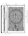
- As shown in
FIGURES 1 and 2 , an exemplary integratedgyro accelerometer device 20 includes asemiconductor substrate layer 32 that includes a semiconductor interferometric fiber-optic gyro (IFOG) 26 and a cantilever strain-resistive beam 21. The cantilever strain-resistive beam 21 includes a resonating component 36. The cantilever strain-resistive beam 21 is driven electrothermally to resonate by means of an implanted piezoresistor driver 36-1. Change in beam resonance (i.e., acceleration along the z-axis) is sensed piezoresistively by an implanted piezoresistor sensor 36-2. The piezoresistor implants (36-1, 36-2) are electrically coupled to a piezoresistor electronic component 36-3. In one embodiment the piezoresistor electronic component 36-3 is also located on the cantilever strain-resistive beam 21. - The piezoresistor electronic component 36-3 includes an oscillator circuit (not shown) for driving the piezoresistor driver 36-1 and a feedback circuit (not shown) for receiving signals from the piezoresistor sensor 36-2. The piezoresistor electronic component 36-3 is connected to the piezoresistor elements (36-1, 36-2) via surface metal traces (not shown). Other surface metal traces (not shown) connect the piezoresistor electronic component 36-3 with one or more substrate die pads (not shown). One or
more bond wires 58 are attached to the substrate die pads and to sensor package lead frame (not shown). - In one embodiment, the resonating cantilever (RC)
beam 21 is formed from a semiconductor material, such as silicon, gallium-arsenide, or comparable material, with a thickness/width/length to allow it to resonate, based on a mass-spring configuration. Force due to acceleration is transformed into a load that acts axially (z-axis) on theRC beam 21. The magnitude of the acceleration is related to the change in the RC beam's resonant frequency, which is sensed based on the frequency of the signal sent to the driver 36-1 and received by the sensor 36-2. The vector component of acceleration is perpendicular to theRC beam 21. A DC voltage is applied with a superimposed sinusoidal signal to the piezoresistor driver 36-1, thus producing cyclic heating and cooling of the driver 36-1, which causes theRC beam 21 to deflect and oscillate. The piezoresistor sensor 36-2 detects change in frequency of theRC beam 21. The resonating frequency change in theRC beam 21 is due to the load generated by the acceleration component along the z-axis. Acceleration sensor resolution is a function of the RC beam material/thickness/width/length. - The
RC beam 21 is created from thesemiconductor substrate 32 using one of the following exemplary methods: laser cut; plasma etch; water jet machined; or other comparable methods (see 54-2). Thesubstrate 32 is attached to asensor package base 22 having a resonating cavity 54-1. The resonating cavity 54-1 is located below theRC beam 21, thus allowing theRC beam 21 to flex along the z-axis. - The IFOG 26 includes an optical waveguide 50-1 that is incorporated on the
substrate 32 surrounding the resonating cantilever component 36 with a ω rotational component wrapped around the vector of acceleration (i.e., around the z-axis). The optical waveguide 50-1 is formed into thesubstrate 32 in a spiral along the X-Y plane or vertically in the Z plane (see 50-2 inFIGURES 3 and 4 ). The IFOG 26 also includes a light source (laser diode) 42, a light detector (photo diode) 44, and IFOG interface electronics 40 (i.e., integrated optics chip (IOC)). The light source (laser diode) 42 and the light detector (photo diode) 44 are in optical communication with the optical waveguide 50-1 formed in the semiconductor substrate. The light source (laser diode) 42, the light detector (photo diode) 44, and/or theIFOG interface electronics 40 are in signal communication with thebond wires 58 via surface metal traces (not shown). The one ormore bond wires 58 are attached to the substrate die pads and to sensor package lead frame (not shown). The IFOG 26 senses a rotational force about an axis (z-axis) that passes through the center of the optical waveguide 50-1 in accordance with known gyro principles. - An example of the resonating cantilever beam accelerometer with implanted piezoresistor elements (36) is shown and described in U.S. Patent No. 3,614,677, the contents of which are hereby incorporated by reference.
- An example of the
semiconductor IFOG 26 is shown and described in U.S. Patent Application No. 2008/0013094 filed July 14, 2006 (now abandoned), the contents of which are hereby incorporated by reference. - An example a semiconductor IFOG and accelerometer located on a resonating beam, as shown and described in U.S. Patent No. 7,929,143, the contents of which are hereby incorporated by reference.
- The components on the
substrate 32 may be covered by a passivation layer, such as glass, for protecting the components. The components may be placed on thesubstrate 32 or created in thesubstrate 32. - A
sensor package lid 23 is hermetically attached to thesensor package base 22 using a hermetic seal, thus encasing theRC beam 21. The resonating cavity 54-1 and the space encapsulated between thesensor package base 22 and a hermetically sealedcover 23 has a vacuum and/or is backfilled with an inert gas. -
FIGURE 5 illustrates a three-accelerometer, three-gyro system 80. The system 80 includes threeintegrated gyro accelerometers integrated gyro accelerometers RC beam 21. Each determined center point is the point at which the z-axis passes through the respective beams. When attached to form the device 80 as shown inFIGURE 5 , those known z-axis points are used to properly orient/attach thegyro accelerometers - While the preferred embodiment of the invention has been illustrated and described, as noted above, many changes can be made without departing from the spirit and scope of the invention. Accordingly, the scope of the invention is not limited by the disclosure of the preferred embodiment. Instead, the invention should be determined entirely by reference to the claims that follow.
Claims (10)
- An integrated interferometric gyroscope and accelerometer device, the device comprising:a substrate comprising:a resonating cantilever beam; andan area that surrounds the resonating cantilever beam;a package comprising a resonating cavity collocated along an acceleration
axis direction with the resonating cantilever beam;a driver incorporated within the resonating cantilever beam, the driver
configured to electrothermally resonate the resonating cantilever beam;a sensor incorporated within the resonating cantilever beam, the sensor
configured to sense a signal that relates to an acceleration force out-of-plane of the resonating cantilever beam; anda semiconductor interferometric optical gyro comprising an optical
waveguide surrounding the resonating cantilever beam on the area of the substrate, the gyro being incorporated to sense rotational motion about an axis approximately equivalent to a vector corresponding to an acceleration force. - The device of Claim 1, wherein the gyro further comprises a light source and a light detector.
- The device of Claim 2, wherein the light detector is a photo diode.
- A method for sensing a rotational force and an acceleration force, the method comprising:electrothermally resonating a resonating cantilever beam flexible from a
substrate that surrounds the resonating cantilever beam;sensing a signal that relates to an acceleration force out-of-plane of the
resonating cantilever beam; andsensing rotational motion of the resonating cantilever beam about an axis
approximately equivalent to a vector corresponding to the acceleration force,wherein sensing rotational motion comprises using a semiconductor
interferometric optical gyro having a waveguide incorporated in the substrate around the resonating cantilever beam. - The method of Claim 4, wherein the gyro further comprises a light source and a light detector.
- The method of Claim 4, wherein the resonating cantilever beam is formed from the same contiguous substrate material.
- The method of Claim 6, wherein the substrate is a single silicon substrate;
and
the light source is formed within a layer of the substrate. - The method of Claim 7, wherein the interferometric optical gyro further comprises interface electronics located at least one of on or in the substrate.
- The method of Claim 4, further comprising hermetically sealing the resonated cantilever beam within the sensor package.
- The method of Claim 4, wherein electrothermally resonating the resonating cantilever beam is performed by a piezoresistor driver and sensing the signal that relates to an acceleration force is performed by a piezoresistor sensor.
Applications Claiming Priority (1)
| Application Number | Priority Date | Filing Date | Title |
|---|---|---|---|
| US13/625,699 US8873029B2 (en) | 2012-09-24 | 2012-09-24 | Coaxial gyro accelerometer in a semiconductor substrate |
Publications (1)
| Publication Number | Publication Date |
|---|---|
| EP2711668A1 true EP2711668A1 (en) | 2014-03-26 |
Family
ID=48748043
Family Applications (1)
| Application Number | Title | Priority Date | Filing Date |
|---|---|---|---|
| EP13175954.0A Withdrawn EP2711668A1 (en) | 2012-09-24 | 2013-07-10 | Coaxial gyro accelerometer in a semiconductor substrate |
Country Status (3)
| Country | Link |
|---|---|
| US (1) | US8873029B2 (en) |
| EP (1) | EP2711668A1 (en) |
| JP (1) | JP2014066700A (en) |
Cited By (1)
| Publication number | Priority date | Publication date | Assignee | Title |
|---|---|---|---|---|
| CN115267971A (en) * | 2022-08-10 | 2022-11-01 | 南京邮电大学 | Photon inertial navigation chip and preparation method thereof |
Families Citing this family (5)
| Publication number | Priority date | Publication date | Assignee | Title |
|---|---|---|---|---|
| US9874581B2 (en) | 2015-05-15 | 2018-01-23 | Honeywell International Inc. | In-situ bias correction for MEMS accelerometers |
| US10330697B2 (en) | 2015-05-15 | 2019-06-25 | Honeywell International Inc. | Active, in-situ, calibration of MEMS accelerometers using optical forces |
| US9983225B2 (en) | 2015-06-29 | 2018-05-29 | Honeywell International Inc. | Optical-mechanical vibrating beam accelerometer |
| US10954708B2 (en) | 2017-07-24 | 2021-03-23 | Gmi Holdings, Inc. | Movable barrier opener with brushless DC motor |
| US10822858B2 (en) | 2017-07-24 | 2020-11-03 | Gmi Holdings, Inc. | Power supply for movable barrier opener with brushless DC motor |
Citations (4)
| Publication number | Priority date | Publication date | Assignee | Title |
|---|---|---|---|---|
| US3614677A (en) | 1966-04-29 | 1971-10-19 | Ibm | Electromechanical monolithic resonator |
| WO1999060337A1 (en) * | 1998-05-15 | 1999-11-25 | Rice Systems, Inc. | Integrated optics rotation sensor |
| EP1878999A1 (en) * | 2006-07-14 | 2008-01-16 | Honeywell International Inc. | Semiconductor substrate for interferometer fiber optic gyroscopes |
| US20110051144A1 (en) * | 2008-12-08 | 2011-03-03 | Honeywell International Inc. | Integrated resonating gyro accelerometer in a semiconductor substrate |
-
2012
- 2012-09-24 US US13/625,699 patent/US8873029B2/en active Active
-
2013
- 2013-07-10 EP EP13175954.0A patent/EP2711668A1/en not_active Withdrawn
- 2013-07-23 JP JP2013152527A patent/JP2014066700A/en not_active Withdrawn
Patent Citations (6)
| Publication number | Priority date | Publication date | Assignee | Title |
|---|---|---|---|---|
| US3614677A (en) | 1966-04-29 | 1971-10-19 | Ibm | Electromechanical monolithic resonator |
| WO1999060337A1 (en) * | 1998-05-15 | 1999-11-25 | Rice Systems, Inc. | Integrated optics rotation sensor |
| EP1878999A1 (en) * | 2006-07-14 | 2008-01-16 | Honeywell International Inc. | Semiconductor substrate for interferometer fiber optic gyroscopes |
| US20080013094A1 (en) | 2006-07-14 | 2008-01-17 | Honeywell International Inc. | Semiconductor substrate for interferometer fiber optic gyroscopes |
| US20110051144A1 (en) * | 2008-12-08 | 2011-03-03 | Honeywell International Inc. | Integrated resonating gyro accelerometer in a semiconductor substrate |
| US7929143B2 (en) | 2008-12-08 | 2011-04-19 | Honeywell International Inc. | Integrated resonating gyro accelerometer in a semiconductor substrate |
Non-Patent Citations (1)
| Title |
|---|
| FRICKE J ET AL: "Cantilever beam accelerometer based on surface micromachining technology", JOURNAL OF MICROMECHANICS & MICROENGINEERING, INSTITUTE OF PHYSICS PUBLISHING, BRISTOL, GB, vol. 3, no. 4, 1 December 1993 (1993-12-01), pages 190 - 192, XP020069382, ISSN: 0960-1317, DOI: 10.1088/0960-1317/3/4/005 * |
Cited By (2)
| Publication number | Priority date | Publication date | Assignee | Title |
|---|---|---|---|---|
| CN115267971A (en) * | 2022-08-10 | 2022-11-01 | 南京邮电大学 | Photon inertial navigation chip and preparation method thereof |
| CN115267971B (en) * | 2022-08-10 | 2024-03-26 | 南京邮电大学 | Photon inertial navigation chip and preparation method thereof |
Also Published As
| Publication number | Publication date |
|---|---|
| US8873029B2 (en) | 2014-10-28 |
| JP2014066700A (en) | 2014-04-17 |
| US20140085624A1 (en) | 2014-03-27 |
Similar Documents
| Publication | Publication Date | Title |
|---|---|---|
| US7929143B2 (en) | Integrated resonating gyro accelerometer in a semiconductor substrate | |
| US8873029B2 (en) | Coaxial gyro accelerometer in a semiconductor substrate | |
| US6311555B1 (en) | Angular rate producer with microelectromechanical system technology | |
| US10214414B2 (en) | Integrated MEMS system | |
| US6671648B2 (en) | Micro inertial measurement unit | |
| US6508122B1 (en) | Microelectromechanical system for measuring angular rate | |
| Acar et al. | MEMS vibratory gyroscopes: structural approaches to improve robustness | |
| KR101779998B1 (en) | Micromachined monolithic 3-axis gyroscope with single drive | |
| US6522992B1 (en) | Core inertial measurement unit | |
| US11852481B2 (en) | MEMS motion sensor and method of manufacturing | |
| Geiger et al. | MEMS IMU for ahrs applications | |
| US20180074090A1 (en) | Multiple degree of freedom mems sensor chip and method for fabricating the same | |
| US11287486B2 (en) | 3D MEMS magnetometer and associated methods | |
| Tang et al. | Silicon bulk micromachined vibratory gyroscope for microspacecraft | |
| US20020183958A1 (en) | Core inertial measurement unit | |
| JP6689227B2 (en) | Gyroscope | |
| US20100251817A1 (en) | Thermal mechanical isolator for vacuum packaging of a disc resonator gyroscope | |
| US9880000B2 (en) | Manufacturing method of inertial sensor and inertial sensor | |
| CN102449434A (en) | Gyroscope packaging assembly | |
| EP1257783A1 (en) | Micro inertial measurement unit | |
| JP4871065B2 (en) | Ring resonator gyroscope with folded cylindrical suspension | |
| EP1878999A1 (en) | Semiconductor substrate for interferometer fiber optic gyroscopes | |
| US20230174371A1 (en) | Mems device | |
| US9790083B2 (en) | Vibrator, manufacturing method of vibrator, electronic device, electronic apparatus, and moving object | |
| EP2515076A1 (en) | Angular velocity detection device |
Legal Events
| Date | Code | Title | Description |
|---|---|---|---|
| PUAI | Public reference made under article 153(3) epc to a published international application that has entered the european phase |
Free format text: ORIGINAL CODE: 0009012 |
|
| 17P | Request for examination filed |
Effective date: 20130710 |
|
| AK | Designated contracting states |
Kind code of ref document: A1 Designated state(s): AL AT BE BG CH CY CZ DE DK EE ES FI FR GB GR HR HU IE IS IT LI LT LU LV MC MK MT NL NO PL PT RO RS SE SI SK SM TR |
|
| AX | Request for extension of the european patent |
Extension state: BA ME |
|
| 17Q | First examination report despatched |
Effective date: 20140929 |
|
| RAP1 | Party data changed (applicant data changed or rights of an application transferred) |
Owner name: HONEYWELL INTERNATIONAL INC. |
|
| STAA | Information on the status of an ep patent application or granted ep patent |
Free format text: STATUS: THE APPLICATION HAS BEEN WITHDRAWN |
|
| 18W | Application withdrawn |
Effective date: 20170410 |