EP2711539A2 - Engine control device - Google Patents
Engine control device Download PDFInfo
- Publication number
- EP2711539A2 EP2711539A2 EP13003938.1A EP13003938A EP2711539A2 EP 2711539 A2 EP2711539 A2 EP 2711539A2 EP 13003938 A EP13003938 A EP 13003938A EP 2711539 A2 EP2711539 A2 EP 2711539A2
- Authority
- EP
- European Patent Office
- Prior art keywords
- opening degree
- engine
- throttle opening
- state
- transient
- Prior art date
- Legal status (The legal status is an assumption and is not a legal conclusion. Google has not performed a legal analysis and makes no representation as to the accuracy of the status listed.)
- Granted
Links
Images

Classifications
-
- F—MECHANICAL ENGINEERING; LIGHTING; HEATING; WEAPONS; BLASTING
- F02—COMBUSTION ENGINES; HOT-GAS OR COMBUSTION-PRODUCT ENGINE PLANTS
- F02P—IGNITION, OTHER THAN COMPRESSION IGNITION, FOR INTERNAL-COMBUSTION ENGINES; TESTING OF IGNITION TIMING IN COMPRESSION-IGNITION ENGINES
- F02P5/00—Advancing or retarding ignition; Control therefor
- F02P5/04—Advancing or retarding ignition; Control therefor automatically, as a function of the working conditions of the engine or vehicle or of the atmospheric conditions
- F02P5/145—Advancing or retarding ignition; Control therefor automatically, as a function of the working conditions of the engine or vehicle or of the atmospheric conditions using electrical means
- F02P5/15—Digital data processing
- F02P5/1502—Digital data processing using one central computing unit
- F02P5/1504—Digital data processing using one central computing unit with particular means during a transient phase, e.g. acceleration, deceleration, gear change
-
- F—MECHANICAL ENGINEERING; LIGHTING; HEATING; WEAPONS; BLASTING
- F02—COMBUSTION ENGINES; HOT-GAS OR COMBUSTION-PRODUCT ENGINE PLANTS
- F02D—CONTROLLING COMBUSTION ENGINES
- F02D9/00—Controlling engines by throttling air or fuel-and-air induction conduits or exhaust conduits
- F02D9/02—Controlling engines by throttling air or fuel-and-air induction conduits or exhaust conduits concerning induction conduits
-
- F—MECHANICAL ENGINEERING; LIGHTING; HEATING; WEAPONS; BLASTING
- F02—COMBUSTION ENGINES; HOT-GAS OR COMBUSTION-PRODUCT ENGINE PLANTS
- F02D—CONTROLLING COMBUSTION ENGINES
- F02D11/00—Arrangements for, or adaptations to, non-automatic engine control initiation means, e.g. operator initiated
- F02D11/06—Arrangements for, or adaptations to, non-automatic engine control initiation means, e.g. operator initiated characterised by non-mechanical control linkages, e.g. fluid control linkages or by control linkages with power drive or assistance
- F02D11/10—Arrangements for, or adaptations to, non-automatic engine control initiation means, e.g. operator initiated characterised by non-mechanical control linkages, e.g. fluid control linkages or by control linkages with power drive or assistance of the electric type
- F02D11/106—Detection of demand or actuation
-
- F—MECHANICAL ENGINEERING; LIGHTING; HEATING; WEAPONS; BLASTING
- F02—COMBUSTION ENGINES; HOT-GAS OR COMBUSTION-PRODUCT ENGINE PLANTS
- F02D—CONTROLLING COMBUSTION ENGINES
- F02D11/00—Arrangements for, or adaptations to, non-automatic engine control initiation means, e.g. operator initiated
- F02D11/06—Arrangements for, or adaptations to, non-automatic engine control initiation means, e.g. operator initiated characterised by non-mechanical control linkages, e.g. fluid control linkages or by control linkages with power drive or assistance
- F02D11/10—Arrangements for, or adaptations to, non-automatic engine control initiation means, e.g. operator initiated characterised by non-mechanical control linkages, e.g. fluid control linkages or by control linkages with power drive or assistance of the electric type
- F02D2011/101—Arrangements for, or adaptations to, non-automatic engine control initiation means, e.g. operator initiated characterised by non-mechanical control linkages, e.g. fluid control linkages or by control linkages with power drive or assistance of the electric type characterised by the means for actuating the throttles
- F02D2011/102—Arrangements for, or adaptations to, non-automatic engine control initiation means, e.g. operator initiated characterised by non-mechanical control linkages, e.g. fluid control linkages or by control linkages with power drive or assistance of the electric type characterised by the means for actuating the throttles at least one throttle being moved only by an electric actuator
-
- F—MECHANICAL ENGINEERING; LIGHTING; HEATING; WEAPONS; BLASTING
- F02—COMBUSTION ENGINES; HOT-GAS OR COMBUSTION-PRODUCT ENGINE PLANTS
- F02D—CONTROLLING COMBUSTION ENGINES
- F02D2200/00—Input parameters for engine control
- F02D2200/02—Input parameters for engine control the parameters being related to the engine
- F02D2200/04—Engine intake system parameters
- F02D2200/0404—Throttle position
-
- F—MECHANICAL ENGINEERING; LIGHTING; HEATING; WEAPONS; BLASTING
- F02—COMBUSTION ENGINES; HOT-GAS OR COMBUSTION-PRODUCT ENGINE PLANTS
- F02D—CONTROLLING COMBUSTION ENGINES
- F02D2200/00—Input parameters for engine control
- F02D2200/60—Input parameters for engine control said parameters being related to the driver demands or status
- F02D2200/602—Pedal position
-
- Y—GENERAL TAGGING OF NEW TECHNOLOGICAL DEVELOPMENTS; GENERAL TAGGING OF CROSS-SECTIONAL TECHNOLOGIES SPANNING OVER SEVERAL SECTIONS OF THE IPC; TECHNICAL SUBJECTS COVERED BY FORMER USPC CROSS-REFERENCE ART COLLECTIONS [XRACs] AND DIGESTS
- Y02—TECHNOLOGIES OR APPLICATIONS FOR MITIGATION OR ADAPTATION AGAINST CLIMATE CHANGE
- Y02T—CLIMATE CHANGE MITIGATION TECHNOLOGIES RELATED TO TRANSPORTATION
- Y02T10/00—Road transport of goods or passengers
- Y02T10/10—Internal combustion engine [ICE] based vehicles
- Y02T10/40—Engine management systems
Definitions
- the present invention relates to an engine control device, and more particularly relates to an engine control device that controls an ignition timing of an engine based on an operating state of the engine.
- engine control devices have a function of setting an ignition timing so that an ignition plug is caused to spark discharge at an appropriate timing according to an operating state of an engine.
- the engine control device executes advance control of advancing an ignition timing.
- the ignition timing is advanced in a transient state where the operating state of the engine shifts from a state of a low engine revolution number to an acceleration state, the ignition timing is excessively advanced with respect to an optimum timing because of factors including a variation in an air-fuel ratio due to a sudden increase in a throttle valve opening degree, a variation in an increase rate of the engine revolution number, and the like. Consequently, it is conceivable that a so-called "acceleration shock" may occur in the vehicle.
- Japanese Paten Application Laid-open Publication No. 2000-9007 relates to an ignition-timing control device of an internal-combustion engine, and discloses the following configuration. That is, when a change amount of a throttle valve opening degree is equal to or larger than a predetermined value, it is determined that an operating state of an engine is in a transient state of shifting to an acceleration state. An ignition timing is then retarded, thereby mitigating a variation in an engine output and suppressing an acceleration shock.
- the vehicle weight is lighter and a response of a vehicle behavior to an engine output is quicker as compared to four-wheeled vehicles. Therefore, it is conceivable that a rider feels uncomfortable with even a slight variation in the engine output.
- general automatic two-wheeled vehicles are configured so that an engine output is transmitted via a drive chain to a drive wheel. Therefore, there is a strong tendency that the drive chain is extended or shortened by even a slight increase or decrease in the engine output and such extension or shortening appears as an acceleration shock. It is thus conceivable that a rider feels uncomfortable with even a slight variation in the engine output. That is, in automatic two-wheeled vehicles particularly, it is conceivable that there is a great demand to sufficiently suppress an acceleration shock that may occur by an unnecessary variation in an engine output when the engine is in an acceleration state.
- the present invention has been achieved in view of the above problems, and an object of the present invention is to provide an engine control device that can detect early and precisely that an operating state of the engine is in a transient state of shifting to an acceleration state and to appropriately control an ignition timing in the transient state, thereby reliably suppressing an acceleration shock to a vehicle.
- a first aspect of the present invention is to provide an engine control device comprising: an electronically-controlled-throttle control unit that calculates a target throttle opening degree based on an accelerator opening degree and feedback-controls an opening degree of a throttle valve so as to match the target throttle opening degree; an ignition-timing control unit that controls an ignition timing of an engine based on an operating state of the engine; a transient-state determination-processing unit that determines whether the operating state of the engine is in a transient state of shifting to an acceleration state based on a change amount of the target throttle opening degree; and a transient-state correction-processing unit that retards the ignition timing by a predetermined amount set by the change amount when the transient-state determination-processing unit determines that the operating state of the engine is in the transient state.
- the change amount is a deviation amount between an amount based on an actual throttle opening degree of the throttle valve and an amount based on the target throttle opening degree.
- the change amount is a deviation amount between a change amount of the actual throttle opening degree and a change amount of the target throttle opening degree.
- the change amount is a deviation amount between a filtering target throttle opening degree having the target throttle opening degree filtered and the target throttle opening degree or a deviation amount between a change amount of the filtering target throttle opening degree and a change amount of the target throttle opening degree.
- the engine control device comprises a transient-state determination-processing unit that determines whether an operating state of an engine is in a transient state of shifting to an acceleration state based on a change amount of a target throttle opening degree and a transient-state correction-processing unit that retards an ignition timing by a predetermined amount set by the change amount when the transient-state determination-processing unit determines that the operating state of the engine is in the transient state.
- the change amount of the target throttle opening degree is used as a parameter for determining an operating state of an engine, and thus it is possible to detect early and precisely that an operating state of the engine is in a transient state of shifting to an acceleration state and to appropriately control an ignition timing in the transient state, thereby reliably suppressing an acceleration shock.
- the change amount is a deviation amount between an amount based on an actual throttle opening degree of a throttle valve and an amount based on a target throttle opening degree. Therefore, by using the deviation amount between the amount based on the actual throttle opening degree of the throttle valve and the amount based on the target throttle opening degree as a parameter for determining an operating state of the engine, it is possible to detect a change amount and a change direction of the actual throttle opening degree of the throttle valve, and thus to detect early and precisely that an operating state of the engine is in a transient state of shifting to an acceleration state.
- the change amount is a deviation amount between a change amount of the actual throttle opening degree and a change amount of the target throttle opening degree. Therefore, by using the deviation amount between the change amount of the actual throttle opening degree of the throttle valve and the change amount of the target throttle opening degree as a parameter for determining an operating state of the engine, it is possible to detect a change in the amount of intake air to the engine at the time of an acceleration operation by a driver, and thus to detect early and precisely that an operating state of the engine is in a transient state of shifting to an acceleration state.
- the change amount is a deviation amount between a filtering target throttle opening degree having the target throttle opening degree filtered and the target throttle opening degree, or a deviation amount between a change amount of the filtering target throttle opening degree and a change amount of the target throttle opening degree.
- FIG. 1 A configuration of an engine control device according to an embodiment of the present invention is explained first in detail with reference to FIG. 1 .
- FIG. 1 is a block diagram of the configuration of the engine control device according to the present embodiment.
- an ECU (Electronic Control Unit) 1 that is the engine control device according to the present embodiment is mounted in a vehicle (not shown), and can control an ignition timing of an ignition plug 2 that ignites mixed air in a combustion chamber of an engine (not shown) mounted in the vehicle at an appropriate timing according to an operating state of the engine.
- the ECU 1 is a component of an electronically-controlled throttle device 3, and can control an opening degree of a throttle valve that is placed in an intake pipe (not shown) connected to the combustion chamber of the engine so as to match a target throttle opening degree.
- the ECU 1 includes a crank-angle detection unit 11, a throttle-opening-degree detection unit 12, an accelerator-opening-degree detection unit 13, an intake-pressure detection unit 14, an engine-temperature detection unit 15, a battery-voltage detection unit 16, an engine-revolution-number calculation unit 17, a throttle-opening-degree calculation unit 18, an accelerator-opening-degree calculation unit 19, an intake-pressure calculation unit 20, an engine-temperature calculation unit 21, a battery-voltage calculation unit 22, an ignition-timing control unit 23, an anti-jerk correction-amount computation unit 24, adders 25a and 25b, an ignition output driver 26, an electronically-controlled-throttle control unit 27, and a motor driving driver 28.
- the crank-angle detection unit 11 acquires an output electric signal of a crank angle sensor 31 that detects a rotation angle of a timing rotor coaxially attached to a crank mechanism that supports a piston, and outputs the acquired output electric signal to the engine-revolution-number calculation unit 17.
- the throttle-opening-degree detection unit 12 acquires an output electric signal of a throttle opening degree sensor 32 that detects an opening degree (hereinafter, "actual throttle opening degree") of a throttle valve of the electronically-controlled throttle device 3, and outputs the acquired output electric signal to the throttle-opening-degree calculation unit 18.
- the accelerator-opening-degree detection unit 13 acquires an output electric signal of an accelerator opening degree sensor 33 that detects an opening degree (hereinafter, "accelerator opening degree") of an accelerator operating member such as an accelerator grip or an accelerator pedal, and outputs the acquired output electric signal to the accelerator-opening-degree calculation unit 19.
- an accelerator opening degree sensor 33 that detects an opening degree (hereinafter, "accelerator opening degree") of an accelerator operating member such as an accelerator grip or an accelerator pedal, and outputs the acquired output electric signal to the accelerator-opening-degree calculation unit 19.
- the intake-pressure detection unit 14 acquires an output electric signal of an intake pressure sensor 34 that detects the pressure of intake air passing through an intake pipe, and outputs the acquired output electric signal to the intake-pressure calculation unit 20.
- the engine-temperature detection unit 15 acquires an output electric signal of an engine temperature sensor 35 that detects a temperature such as a water temperature of an engine of a vehicle, and outputs the acquired output electric signal to the engine-temperature calculation unit 21.
- the battery-voltage detection unit 16 detects a voltage between terminals of a battery 36 mounted in the vehicle, and outputs the detected electric signal to the battery-voltage calculation unit 22.
- the engine-revolution-number calculation unit 17 calculates an engine revolution number based on an output signal from the crank-angle detection unit 11, and outputs an electric signal indicating the calculated engine revolution number to the ignition-timing control unit 23, the anti-jerk correction-amount computation unit 24, and the electronically-controlled-throttle control unit 27.
- the throttle-opening-degree calculation unit 18 calculates an actual throttle opening degree based on an output signal from the throttle-opening-degree detection unit 12, and outputs an electric signal indicating the calculated actual throttle opening degree to the ignition-timing control unit 23, the anti-jerk correction-amount computation unit 24, and the electronically-controlled-throttle control unit 27.
- the accelerator-opening-degree calculation unit 19 calculates an accelerator opening degree based on an output signal from the accelerator-opening-degree detection unit 13, and outputs an electric signal indicating the calculated accelerator opening degree to the ignition-timing control unit 23 and the electronically-controlled-throttle control unit 27.
- the intake-pressure calculation unit 20 calculates the pressure of intake air based on an output signal from the intake-pressure detection unit 14, and outputs an electric signal indicating the calculated pressure of the intake air to the ignition-timing control unit 23 and the electronically-controlled-throttle control unit 27.
- the engine-temperature calculation unit 21 calculates an engine temperature based on an output signal from the engine-temperature detection unit 15, and outputs an electric signal indicating the calculated engine temperature to the ignition-timing control unit 23 and the electronically-controlled-throttle control unit 27.
- the battery-voltage calculation unit 22 calculates a voltage between terminals of the battery 36 based on an output signal from the battery-voltage detection unit 16, and outputs an electric signal indicating the calculated voltage between terminals of the battery 36 to the ignition-timing control unit 23, the electronically-controlled-throttle control unit 27, and the motor driving driver 28.
- the ignition-timing control unit 23 includes a basic-ignition-timing computation unit 23a and an ignition-timing correction-amount computation unit 23b, and sets an ignition timing of the ignition plug 2 to an appropriate timing according to an operating state of an engine.
- the basic-ignition-timing computation unit 23a calculates a basic ignition timing of the ignition plug 2 based on an engine revolution number calculated by the engine-revolution-number calculation unit 17 and an actual throttle opening degree calculated by the throttle-opening-degree calculation unit 18.
- the ignition-timing correction-amount computation unit 23b calculates a correction amount of the basic ignition timing of the ignition plug 2 based on an accelerator opening degree calculated by the accelerator-opening-degree calculation unit 19, the pressure of intake air calculated by the intake-pressure calculation unit 20, an engine temperature calculated by the engine-temperature calculation unit 21, and a voltage between terminals of the battery 36 calculated by the battery-voltage calculation unit 22.
- the anti-jerk correction-amount computation unit 24 includes a transient-state determination-processing unit 24a and a transient-state correction-processing unit 24b, and retards an ignition timing of the ignition plug 2 by a predetermined amount when an operating state of an engine is in a transient state of shifting to an acceleration state.
- the transient-state determination-processing unit 24a determines whether the engine is in a transient state of shifting to an acceleration state based on a change amount of a target opening degree (hereinafter, "target throttle opening degree”) of a throttle valve of the electronically-controlled throttle device 3.
- the transient-state correction-processing unit 24b retards the ignition timing of the ignition plug 2 by a predetermined amount set by the change amount of the target throttle opening degree when the transient-state determination-processing unit 24a determines that an engine is in a transient state of shifting to an acceleration state.
- the adder 25a adds a correction amount calculated by the ignition-timing correction-amount computation unit 23b to a basic ignition timing calculated by the basic-ignition-timing computation unit 23a, thereby calculating an ignition timing of the ignition plug 2 according to an operating state of an engine.
- the adder 25b adds a transient-state correction amount calculated by the anti-jerk correction-amount computation unit 24 to the ignition timing of the ignition plug 2 calculated by the adder 25a, thereby calculating an ignition timing of the ignition plug 2 when an engine is in a transient state of shifting to an acceleration state.
- the ignition output driver 26 controls an ignition operation of the ignition plug 2 according to the ignition timing of the ignition plug 2 output from the adder 25b.
- the electronically-controlled-throttle control unit 27 includes a target-opening-degree calculation unit 27a and a control-deviation calculation unit 27b, and feedback-controls an actual throttle opening degree so as to match a target throttle opening degree.
- the target-opening-degree calculation unit 27a calculates a target throttle opening degree based on an engine revolution number calculated by the engine-revolution-number calculation unit 17, an actual throttle opening degree calculated by the throttle-opening-degree calculation unit 18, an accelerator opening degree calculated by the accelerator-opening-degree calculation unit 19, the pressure of intake air calculated by the intake-pressure calculation unit 20, an engine temperature calculated by the engine-temperature calculation unit 21, and a voltage between terminals of the battery 36 calculated by the battery-voltage calculation unit 22.
- the target-opening-degree calculation unit 27a outputs the calculated target throttle opening degree to the control-deviation calculation unit 27b and the motor driving driver 28.
- the control-deviation calculation unit 27b outputs a deviation between the actual throttle opening degree calculated by the throttle-opening-degree calculation unit 18 and the target throttle opening degree calculated by the target-opening-degree calculation unit 27a to the motor driving driver 28 as a control deviation.
- the motor driving driver 28 calculates an operation amount of a motor that drives a throttle valve of the electronically-controlled throttle device 3 based on a target throttle opening degree output from the target-opening-degree calculation unit 27a and a control deviation output from the control-deviation calculation unit 27b and drives the motor in the calculated operation amount, thereby controlling an opening degree of the throttle valve of the electronically-controlled throttle device 3 so as to match the target throttle opening degree.
- the engine control device having the above configuration performs the following anti-jerk control process, so that it is possible to detect early and precisely that an operating state of an engine is in a transient state of shifting to an acceleration state and to appropriately control an ignition timing of the engine in the transient state, thereby reliably controlling an acceleration shock.
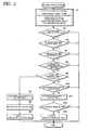
- An operation of the engine control device at the time of performing such anti-jerk control process is explained below in detail with reference to a flowchart of FIG. 2 .
- FIG. 2 is a flowchart of a flow of the anti-jerk control process according to the present embodiment.
- the flowchart shown in FIG. 2 starts at a timing that an ignition switch of a vehicle is switched on from an off-state and a substantial operation of the ECU 1 starts, and the anti-jerk control process proceeds to Step S1.
- the anti-jerk control process is repeated for every predetermined control period.
- a program and data that are required for performing the anti-jerk control process those stored in a memory (not shown) of the ECU 1 are used.
- the transient-state determination-processing unit 24a detects the current gear position of the vehicle by using a gear position sensor attached to a transmission (not shown) of the vehicle and reads, with respect to the detected gear position, a predetermined throttle opening degree (a predetermined TH opening degree), a predetermined throttle-opening degree change amount (a predetermined opening-degree change amount), predetermined engine revolution numbers NE1 and NE2 ( ⁇ NE1) (predetermined NE1 and NE2), a retardation duration time, a predetermined retardation amount, and a predetermined return amount from table-type data that indicates correspondence relationships between these values and the respective gear positions.
- the process in Step S1 is then completed and the transient-state determination-processing unit 24a proceeds the anti-jerk control process to Step S2.
- the transient-state determination-processing unit 24a discriminates whether an actual throttle opening degree (a TH opening degree) calculated by the throttle-opening-degree calculation unit 18 is a large opening degree equal to or larger than the predetermined throttle opening degree acquired by the process in Step S1. As a result of discrimination, when the actual throttle opening degree is a small opening degree less than the predetermined throttle opening degree, the transient-state determination-processing unit 24a ends the current anti-jerk control process. On the other hand, when the actual throttle opening degree is a large opening degree equal to or larger than the predetermined throttle opening degree, the transient-state determination-processing unit 24a proceeds the anti-jerk control process to Step S3.
- the transient-state determination-processing unit 24a discriminates whether an engine revolution number (an Eng revolution number) calculated by the engine-revolution-number calculation unit 17 is a low revolution number equal to or less than the predetermined engine revolution number NE1 acquired by the process in Step S1. As a result of discrimination, when the engine revolution number is a high revolution number larger than the predetermined engine revolution number, the transient-state determination-processing unit 24a ends the current anti-jerk control process. On the other hand, when the engine revolution number is a low revolution number equal to or less than the predetermined engine revolution number NE1, the transient-state determination-processing unit 24a proceeds the anti-jerk control process to Step S4.
- the transient-state determination-processing unit 24a discriminates whether the engine revolution number (the Eng revolution number) calculated by the engine-revolution-number calculation unit 17 is a high revolution number equal to or larger than the predetermined engine revolution number NE2 acquired by the process in Step S1. As a result of discrimination, when the engine revolution number is a low revolution number less than the predetermined engine revolution number, the transient-state determination-processing unit 24a ends the current anti-jerk control process. On the other hand, when the engine revolution number is a high revolution number equal to or larger than the predetermined engine revolution number NE2, the transient-state determination-processing unit 24a proceeds the anti-jerk control process to Step S5.
- the transient-state determination-processing unit 24a determines whether an operating state of an engine is in a transient state of shifting to an acceleration state based on a change amount of a target throttle opening degree (a target opening degree) calculated by the target-opening-degree calculation unit 27a by determining whether the a change amount is equal to or larger than the predetermined opening-degree change amount.
- a deviation amount between a value calculated by the process before n control period (n is a natural number) in the target-opening-degree calculation unit 27a and a value calculated by the current process in the target-opening-degree calculation unit 27a can be used.
- n is a natural number
- it is convenient to use a deviation between the actual throttle opening degree (the TH opening degree) calculated by the throttle-opening-degree calculation unit 18 and the target throttle opening degree calculated by the target-opening-degree calculation unit 27a that is, a value obtained by subtracting the actual throttle opening degree calculated by the current process from the target throttle opening degree calculated by the current process, because the process ends by the current process.
- a deviation amount between a change amount of the actual throttle opening degree (a deviation amount between a current value and a previous value of the actual throttle opening degree calculated by the throttle-opening-degree calculation unit 18) and the change amount of the target throttle opening degree (a value obtained by subtracting the change amount of the actual throttle opening degree from the change amount of the target throttle opening degree) can be used.
- a deviation amount between a filtering target throttle opening degree having the target throttle opening degree filtered and the target throttle opening degree or a deviation amount between a change amount of the filtering target throttle opening degree and the change amount of the target throttle opening degree can be used.
- the filtering target throttle opening degree include a value obtained by moving-averaging time-series values of the target throttle opening degree and a minimum value of the time-series values of the target throttle opening degree.
- the transient-state determination-processing unit 24a ends the current anti-jerk control process.
- the transient-state determination-processing unit 24a determines that the target throttle opening degree has suddenly changed and proceeds the anti-jerk control process to Step S6.
- the transient-state determination-processing unit 24a discriminates whether a value of a flag F_AJKACT that indicates whether the anti-jerk control process is being performed is 1, thereby discriminating whether the anti-jerk has already been performed. As a result of discrimination, when the value of the flag F_AJKACT is 0, the transient-state determination-processing unit 24a determines that the anti-jerk control process has not been performed yet and proceeds the anti-jerk control process to Step S7. On the other hand, when the value of the flag F_AJKACT is 1, the transient-state determination-processing unit 24a determines that the anti-jerk control process has already been performed and proceeds the anti-jerk control process to Step S10.
- the transient-state correction-processing unit 24b calculates a correction amount of an ignition timing of the ignition plug 2 as a transient-state correction amount so as to execute retard control of the ignition timing of the ignition plug 2 according to the predetermined retardation amount acquired by the process in Step S1, and outputs the calculated transient-state correction amount to the adder 25b.
- a deviation between an actual throttle opening degree and a target throttle opening degree is equal to or larger than a predetermined opening-degree change amount
- retard control of retarding the ignition timing of the ignition plug 2 by a predetermined amount is executed.
- a retardation amount can be variably set according to the magnitude of the deviation.
- the process in Step S7 is then completed and the transient-state determination-processing unit 24a proceeds the anti-jerk control process to Step S8.
- the transient-state correction-processing unit 24b sets the retardation duration time acquired by the process in Step S1 in a subtraction timer for measuring a retard control time of the ignition timing of the ignition plug 2, and switches on the subtraction timer.
- the process in Step S8 is then completed and the transient-state determination-processing unit 24a proceeds the anti-jerk control process to Step S9.
- the transient-state correction-processing unit 24b sets the value of the flag F_AJKACT that indicates whether the anti-jerk control process is being performed to 1 (the anti-jerk control process being performed). The process in Step S9 is then completed and the current anti-jerk control process ends.
- the transient-state correction-processing unit 24b discriminates whether a value of the subtraction timer switched on by the process in Step S8 is 0, thereby discriminating whether the retard control of the ignition timing of the ignition plug 2 is continuously executed for the retardation duration time acquired by the process in Step S1. As a result of discrimination, when the retard control is not continuously executed for the retardation duration time, the transient-state correction-processing unit 24b ends the current anti-jerk control process. On the other hand, when the retard control is continuously executed for the retardation duration time, the transient-state correction-processing unit 24b proceeds the anti-jerk control process to Step S11.
- the transient-state correction-processing unit 24b calculates the correction amount of the ignition timing of the ignition plug 2 as a transient-state correction amount so as to execute return control of gradually returning the ignition timing of the ignition plug 2 to an ignition timing output from the adder 25a according to the predetermined return amount acquired by the process in Step S1, and outputs the calculated transient-state correction amount to the adder 25b.
- the retard control for the retardation duration time and then executing the return control, it is possible to suppress an unnecessary variation in an engine output, thereby suppressing occurrence of an unnecessary shock in a vehicle.
- the process in Step S11 is then completed, and the transient-state determination-processing unit 24a proceeds the anti-jerk control process to Step S12.
- the transient-state correction-processing unit 24b discriminates whether the ignition timing of the ignition plug 2 returns to the ignition timing output from the adder 25a. As a result of discrimination, when the ignition timing does not return, the transient-state correction-processing unit 24b ends the current anti-jerk control process. On the other hand, when the ignition timing returns, the transient-state correction-processing unit 24b proceeds the anti-jerk control process to Step S13.
- the transient-state correction-processing unit 24b sets the value of the flag F_AJKACT that indicates whether the anti-jerk control process is being performed to 0 (the anti-jerk control process being stopped). The process in Step S13 is then completed and the current anti-jerk control process ends.
- the transient-state determination-processing unit 24a determines whether an operating state of an engine is in a transient state of shifting to an acceleration state based on a change amount of a target throttle opening degree.
- the transient-state correction-processing unit 24b retards an ignition timing of the engine by a predetermined amount set by the change amount of the target throttle opening degree.
- the change amount of the target throttle opening degree is used as a parameter for determining an operating state of an engine, it is possible to detect early and precisely that an operating state of an engine is in a transient state of shifting to an acceleration state and to appropriately control an ignition timing in the transient state, thereby reliably suppressing an acceleration shock.
- the transient-state determination-processing unit 24a can use a deviation amount between an actual throttle opening degree and a target throttle opening degree as the change amount of the target throttle opening degree. Therefore, it is possible to detect a change amount and a change direction of the actual throttle opening degree and thus to detect early and precisely that an operating state of an engine is in a transient state of shifting to an acceleration state.
- the transient-state determination-processing unit 24a can use a deviation amount between a change amount of the actual throttle opening degree and a change amount of the target throttle opening degree as the change amount of the target throttle opening degree. Therefore, it is possible to detect a change in the amount of intake air to an engine at the time of an acceleration operation by a driver, and thus to detect early and precisely that an operating state of the engine is in a transient state of shifting to an acceleration state.
- the transient-state determination-processing unit 24a can use, as the change amount of the target throttle opening degree, a deviation amount between a filtering target throttle opening degree having the target throttle opening degree filtered and the target throttle opening degree or a deviation amount between a change amount of the filtering target throttle opening degree and a change amount of the target throttle opening degree. Therefore, it is possible to reduce an influence of noise from an accelerator operating member, and thus to detect early and precisely that an operating state of the engine is in a transient state of shifting to an acceleration state.
- the type, the arrangement, the number, and the like of the constituent elements are not limited to those in the embodiment explained above, and it is needless to mention that the constituent elements can be modified as appropriate without departing from the scope of the invention, such as appropriately replacing these elements by other ones having identical operational effects.
Landscapes
- Engineering & Computer Science (AREA)
- Chemical & Material Sciences (AREA)
- Combustion & Propulsion (AREA)
- Mechanical Engineering (AREA)
- General Engineering & Computer Science (AREA)
- Theoretical Computer Science (AREA)
- Signal Processing (AREA)
- Electrical Control Of Ignition Timing (AREA)
- Combined Controls Of Internal Combustion Engines (AREA)
- Control Of Throttle Valves Provided In The Intake System Or In The Exhaust System (AREA)
Abstract
Description
- The present invention relates to an engine control device, and more particularly relates to an engine control device that controls an ignition timing of an engine based on an operating state of the engine.
- Generally, engine control devices have a function of setting an ignition timing so that an ignition plug is caused to spark discharge at an appropriate timing according to an operating state of an engine.
- Specifically, when an operating state of an engine is in an acceleration state where an engine revolution number (engine speed) is increased, the engine control device executes advance control of advancing an ignition timing. However, when the ignition timing is advanced in a transient state where the operating state of the engine shifts from a state of a low engine revolution number to an acceleration state, the ignition timing is excessively advanced with respect to an optimum timing because of factors including a variation in an air-fuel ratio due to a sudden increase in a throttle valve opening degree, a variation in an increase rate of the engine revolution number, and the like. Consequently, it is conceivable that a so-called "acceleration shock" may occur in the vehicle.
- Under such circumstances, Japanese Paten Application Laid-open Publication No.
2000-9007 - However, according to the studies by the present inventors, in the configuration of Japanese Paten Application Laid-open Publication No.
2000-9007 - Further, according to the studies by the present inventors, particularly in automatic two-wheeled vehicles, the vehicle weight is lighter and a response of a vehicle behavior to an engine output is quicker as compared to four-wheeled vehicles. Therefore, it is conceivable that a rider feels uncomfortable with even a slight variation in the engine output. Further, general automatic two-wheeled vehicles are configured so that an engine output is transmitted via a drive chain to a drive wheel. Therefore, there is a strong tendency that the drive chain is extended or shortened by even a slight increase or decrease in the engine output and such extension or shortening appears as an acceleration shock. It is thus conceivable that a rider feels uncomfortable with even a slight variation in the engine output. That is, in automatic two-wheeled vehicles particularly, it is conceivable that there is a great demand to sufficiently suppress an acceleration shock that may occur by an unnecessary variation in an engine output when the engine is in an acceleration state.
- The present invention has been achieved in view of the above problems, and an object of the present invention is to provide an engine control device that can detect early and precisely that an operating state of the engine is in a transient state of shifting to an acceleration state and to appropriately control an ignition timing in the transient state, thereby reliably suppressing an acceleration shock to a vehicle.
- To achieve the above object, a first aspect of the present invention is to provide an engine control device comprising: an electronically-controlled-throttle control unit that calculates a target throttle opening degree based on an accelerator opening degree and feedback-controls an opening degree of a throttle valve so as to match the target throttle opening degree; an ignition-timing control unit that controls an ignition timing of an engine based on an operating state of the engine; a transient-state determination-processing unit that determines whether the operating state of the engine is in a transient state of shifting to an acceleration state based on a change amount of the target throttle opening degree; and a transient-state correction-processing unit that retards the ignition timing by a predetermined amount set by the change amount when the transient-state determination-processing unit determines that the operating state of the engine is in the transient state.
- According to a second aspect of the present invention, in addition to the first aspect, the change amount is a deviation amount between an amount based on an actual throttle opening degree of the throttle valve and an amount based on the target throttle opening degree.
- According to a third aspect of the present invention, in addition to the second aspect, the change amount is a deviation amount between a change amount of the actual throttle opening degree and a change amount of the target throttle opening degree.
- According to a fourth aspect of the present invention, in addition to the first aspect, the change amount is a deviation amount between a filtering target throttle opening degree having the target throttle opening degree filtered and the target throttle opening degree or a deviation amount between a change amount of the filtering target throttle opening degree and a change amount of the target throttle opening degree.
- The engine control device according to the first aspect of the present invention comprises a transient-state determination-processing unit that determines whether an operating state of an engine is in a transient state of shifting to an acceleration state based on a change amount of a target throttle opening degree and a transient-state correction-processing unit that retards an ignition timing by a predetermined amount set by the change amount when the transient-state determination-processing unit determines that the operating state of the engine is in the transient state. Therefore, the change amount of the target throttle opening degree is used as a parameter for determining an operating state of an engine, and thus it is possible to detect early and precisely that an operating state of the engine is in a transient state of shifting to an acceleration state and to appropriately control an ignition timing in the transient state, thereby reliably suppressing an acceleration shock.
- In the engine control device according to the second aspect of the present invention, the change amount is a deviation amount between an amount based on an actual throttle opening degree of a throttle valve and an amount based on a target throttle opening degree. Therefore, by using the deviation amount between the amount based on the actual throttle opening degree of the throttle valve and the amount based on the target throttle opening degree as a parameter for determining an operating state of the engine, it is possible to detect a change amount and a change direction of the actual throttle opening degree of the throttle valve, and thus to detect early and precisely that an operating state of the engine is in a transient state of shifting to an acceleration state.
- In the engine control device according to the third aspect of the present invention, the change amount is a deviation amount between a change amount of the actual throttle opening degree and a change amount of the target throttle opening degree. Therefore, by using the deviation amount between the change amount of the actual throttle opening degree of the throttle valve and the change amount of the target throttle opening degree as a parameter for determining an operating state of the engine, it is possible to detect a change in the amount of intake air to the engine at the time of an acceleration operation by a driver, and thus to detect early and precisely that an operating state of the engine is in a transient state of shifting to an acceleration state.
- In the engine control device according to the fourth aspect of the present invention, the change amount is a deviation amount between a filtering target throttle opening degree having the target throttle opening degree filtered and the target throttle opening degree, or a deviation amount between a change amount of the filtering target throttle opening degree and a change amount of the target throttle opening degree. By using the deviation amount between the filtering target throttle opening degree having the target throttle opening degree filtered and the target throttle opening degree or the deviation amount between the change amount of the filtering target throttle opening degree and the change amount of the target throttle opening degree as a parameter for determining an operating state of the engine, it is possible to detect early and precisely that an operating state of the engine is in a transient state of shifting to an acceleration state without any influence of noise caused by an unnecessary or contingent operation of an accelerator operating member.
-
-
FIG. 1 is a block diagram of a configuration of an engine control device according to an embodiment of the present invention; and -
FIG. 2 is a flowchart of a flow of an anti-jerk control process according to the present embodiment. - An engine control device according to an embodiment of the present invention is explained below in detail with reference to the accompanying drawings.
- A configuration of an engine control device according to an embodiment of the present invention is explained first in detail with reference to
FIG. 1 . -
FIG. 1 is a block diagram of the configuration of the engine control device according to the present embodiment. - As shown in
FIG. 1 , an ECU (Electronic Control Unit) 1 that is the engine control device according to the present embodiment is mounted in a vehicle (not shown), and can control an ignition timing of anignition plug 2 that ignites mixed air in a combustion chamber of an engine (not shown) mounted in the vehicle at an appropriate timing according to an operating state of the engine. Further, theECU 1 is a component of an electronically-controlled throttle device 3, and can control an opening degree of a throttle valve that is placed in an intake pipe (not shown) connected to the combustion chamber of the engine so as to match a target throttle opening degree. - The
ECU 1 includes a crank-angle detection unit 11, a throttle-opening-degree detection unit 12, an accelerator-opening-degree detection unit 13, an intake-pressure detection unit 14, an engine-temperature detection unit 15, a battery-voltage detection unit 16, an engine-revolution-number calculation unit 17, a throttle-opening-degree calculation unit 18, an accelerator-opening-degree calculation unit 19, an intake-pressure calculation unit 20, an engine-temperature calculation unit 21, a battery-voltage calculation unit 22, an ignition-timing control unit 23, an anti-jerk correction-amount computation unit 24,adders ignition output driver 26, an electronically-controlled-throttle control unit 27, and amotor driving driver 28. - The crank-angle detection unit 11 acquires an output electric signal of a
crank angle sensor 31 that detects a rotation angle of a timing rotor coaxially attached to a crank mechanism that supports a piston, and outputs the acquired output electric signal to the engine-revolution-number calculation unit 17. The throttle-opening-degree detection unit 12 acquires an output electric signal of a throttleopening degree sensor 32 that detects an opening degree (hereinafter, "actual throttle opening degree") of a throttle valve of the electronically-controlled throttle device 3, and outputs the acquired output electric signal to the throttle-opening-degree calculation unit 18. The accelerator-opening-degree detection unit 13 acquires an output electric signal of an acceleratoropening degree sensor 33 that detects an opening degree (hereinafter, "accelerator opening degree") of an accelerator operating member such as an accelerator grip or an accelerator pedal, and outputs the acquired output electric signal to the accelerator-opening-degree calculation unit 19. - The intake-pressure detection unit 14 acquires an output electric signal of an
intake pressure sensor 34 that detects the pressure of intake air passing through an intake pipe, and outputs the acquired output electric signal to the intake-pressure calculation unit 20. The engine-temperature detection unit 15 acquires an output electric signal of anengine temperature sensor 35 that detects a temperature such as a water temperature of an engine of a vehicle, and outputs the acquired output electric signal to the engine-temperature calculation unit 21. The battery-voltage detection unit 16 detects a voltage between terminals of abattery 36 mounted in the vehicle, and outputs the detected electric signal to the battery-voltage calculation unit 22. - The engine-revolution-
number calculation unit 17 calculates an engine revolution number based on an output signal from the crank-angle detection unit 11, and outputs an electric signal indicating the calculated engine revolution number to the ignition-timing control unit 23, the anti-jerk correction-amount computation unit 24, and the electronically-controlled-throttle control unit 27. The throttle-opening-degree calculation unit 18 calculates an actual throttle opening degree based on an output signal from the throttle-opening-degree detection unit 12, and outputs an electric signal indicating the calculated actual throttle opening degree to the ignition-timing control unit 23, the anti-jerk correction-amount computation unit 24, and the electronically-controlled-throttle control unit 27. The accelerator-opening-degree calculation unit 19 calculates an accelerator opening degree based on an output signal from the accelerator-opening-degree detection unit 13, and outputs an electric signal indicating the calculated accelerator opening degree to the ignition-timing control unit 23 and the electronically-controlled-throttle control unit 27. - The intake-
pressure calculation unit 20 calculates the pressure of intake air based on an output signal from the intake-pressure detection unit 14, and outputs an electric signal indicating the calculated pressure of the intake air to the ignition-timing control unit 23 and the electronically-controlled-throttle control unit 27. The engine-temperature calculation unit 21 calculates an engine temperature based on an output signal from the engine-temperature detection unit 15, and outputs an electric signal indicating the calculated engine temperature to the ignition-timing control unit 23 and the electronically-controlled-throttle control unit 27. The battery-voltage calculation unit 22 calculates a voltage between terminals of thebattery 36 based on an output signal from the battery-voltage detection unit 16, and outputs an electric signal indicating the calculated voltage between terminals of thebattery 36 to the ignition-timing control unit 23, the electronically-controlled-throttle control unit 27, and themotor driving driver 28. - The ignition-
timing control unit 23 includes a basic-ignition-timing computation unit 23a and an ignition-timing correction-amount computation unit 23b, and sets an ignition timing of theignition plug 2 to an appropriate timing according to an operating state of an engine. The basic-ignition-timing computation unit 23a calculates a basic ignition timing of theignition plug 2 based on an engine revolution number calculated by the engine-revolution-number calculation unit 17 and an actual throttle opening degree calculated by the throttle-opening-degree calculation unit 18. The ignition-timing correction-amount computation unit 23b calculates a correction amount of the basic ignition timing of theignition plug 2 based on an accelerator opening degree calculated by the accelerator-opening-degree calculation unit 19, the pressure of intake air calculated by the intake-pressure calculation unit 20, an engine temperature calculated by the engine-temperature calculation unit 21, and a voltage between terminals of thebattery 36 calculated by the battery-voltage calculation unit 22. - The anti-jerk correction-
amount computation unit 24 includes a transient-state determination-processing unit 24a and a transient-state correction-processing unit 24b, and retards an ignition timing of theignition plug 2 by a predetermined amount when an operating state of an engine is in a transient state of shifting to an acceleration state. The transient-state determination-processing unit 24a determines whether the engine is in a transient state of shifting to an acceleration state based on a change amount of a target opening degree (hereinafter, "target throttle opening degree") of a throttle valve of the electronically-controlled throttle device 3. The transient-state correction-processing unit 24b retards the ignition timing of theignition plug 2 by a predetermined amount set by the change amount of the target throttle opening degree when the transient-state determination-processing unit 24a determines that an engine is in a transient state of shifting to an acceleration state. - The
adder 25a adds a correction amount calculated by the ignition-timing correction-amount computation unit 23b to a basic ignition timing calculated by the basic-ignition-timing computation unit 23a, thereby calculating an ignition timing of theignition plug 2 according to an operating state of an engine. Theadder 25b adds a transient-state correction amount calculated by the anti-jerk correction-amount computation unit 24 to the ignition timing of theignition plug 2 calculated by theadder 25a, thereby calculating an ignition timing of theignition plug 2 when an engine is in a transient state of shifting to an acceleration state. Theignition output driver 26 controls an ignition operation of theignition plug 2 according to the ignition timing of theignition plug 2 output from theadder 25b. - The electronically-controlled-
throttle control unit 27 includes a target-opening-degree calculation unit 27a and a control-deviation calculation unit 27b, and feedback-controls an actual throttle opening degree so as to match a target throttle opening degree. The target-opening-degree calculation unit 27a calculates a target throttle opening degree based on an engine revolution number calculated by the engine-revolution-number calculation unit 17, an actual throttle opening degree calculated by the throttle-opening-degree calculation unit 18, an accelerator opening degree calculated by the accelerator-opening-degree calculation unit 19, the pressure of intake air calculated by the intake-pressure calculation unit 20, an engine temperature calculated by the engine-temperature calculation unit 21, and a voltage between terminals of thebattery 36 calculated by the battery-voltage calculation unit 22. The target-opening-degree calculation unit 27a outputs the calculated target throttle opening degree to the control-deviation calculation unit 27b and themotor driving driver 28. The control-deviation calculation unit 27b outputs a deviation between the actual throttle opening degree calculated by the throttle-opening-degree calculation unit 18 and the target throttle opening degree calculated by the target-opening-degree calculation unit 27a to themotor driving driver 28 as a control deviation. - The
motor driving driver 28 calculates an operation amount of a motor that drives a throttle valve of the electronically-controlled throttle device 3 based on a target throttle opening degree output from the target-opening-degree calculation unit 27a and a control deviation output from the control-deviation calculation unit 27b and drives the motor in the calculated operation amount, thereby controlling an opening degree of the throttle valve of the electronically-controlled throttle device 3 so as to match the target throttle opening degree. - The engine control device having the above configuration performs the following anti-jerk control process, so that it is possible to detect early and precisely that an operating state of an engine is in a transient state of shifting to an acceleration state and to appropriately control an ignition timing of the engine in the transient state, thereby reliably controlling an acceleration shock. An operation of the engine control device at the time of performing such anti-jerk control process is explained below in detail with reference to a flowchart of
FIG. 2 . -
FIG. 2 is a flowchart of a flow of the anti-jerk control process according to the present embodiment. - The flowchart shown in
FIG. 2 starts at a timing that an ignition switch of a vehicle is switched on from an off-state and a substantial operation of theECU 1 starts, and the anti-jerk control process proceeds to Step S1. The anti-jerk control process is repeated for every predetermined control period. As a program and data that are required for performing the anti-jerk control process, those stored in a memory (not shown) of theECU 1 are used. - In the process in Step S1, the transient-state determination-processing
unit 24a detects the current gear position of the vehicle by using a gear position sensor attached to a transmission (not shown) of the vehicle and reads, with respect to the detected gear position, a predetermined throttle opening degree (a predetermined TH opening degree), a predetermined throttle-opening degree change amount (a predetermined opening-degree change amount), predetermined engine revolution numbers NE1 and NE2 (<NE1) (predetermined NE1 and NE2), a retardation duration time, a predetermined retardation amount, and a predetermined return amount from table-type data that indicates correspondence relationships between these values and the respective gear positions. The process in Step S1 is then completed and the transient-state determination-processingunit 24a proceeds the anti-jerk control process to Step S2. - In the process in Step S2, the transient-state determination-processing
unit 24a discriminates whether an actual throttle opening degree (a TH opening degree) calculated by the throttle-opening-degree calculation unit 18 is a large opening degree equal to or larger than the predetermined throttle opening degree acquired by the process in Step S1. As a result of discrimination, when the actual throttle opening degree is a small opening degree less than the predetermined throttle opening degree, the transient-state determination-processingunit 24a ends the current anti-jerk control process. On the other hand, when the actual throttle opening degree is a large opening degree equal to or larger than the predetermined throttle opening degree, the transient-state determination-processingunit 24a proceeds the anti-jerk control process to Step S3. - In the process in Step S3, the transient-state determination-processing
unit 24a discriminates whether an engine revolution number (an Eng revolution number) calculated by the engine-revolution-number calculation unit 17 is a low revolution number equal to or less than the predetermined engine revolution number NE1 acquired by the process in Step S1. As a result of discrimination, when the engine revolution number is a high revolution number larger than the predetermined engine revolution number, the transient-state determination-processingunit 24a ends the current anti-jerk control process. On the other hand, when the engine revolution number is a low revolution number equal to or less than the predetermined engine revolution number NE1, the transient-state determination-processingunit 24a proceeds the anti-jerk control process to Step S4. - In the process in Step S4, the transient-state determination-processing
unit 24a discriminates whether the engine revolution number (the Eng revolution number) calculated by the engine-revolution-number calculation unit 17 is a high revolution number equal to or larger than the predetermined engine revolution number NE2 acquired by the process in Step S1. As a result of discrimination, when the engine revolution number is a low revolution number less than the predetermined engine revolution number, the transient-state determination-processingunit 24a ends the current anti-jerk control process. On the other hand, when the engine revolution number is a high revolution number equal to or larger than the predetermined engine revolution number NE2, the transient-state determination-processingunit 24a proceeds the anti-jerk control process to Step S5. - In the process in Step S5, the transient-state determination-processing
unit 24a determines whether an operating state of an engine is in a transient state of shifting to an acceleration state based on a change amount of a target throttle opening degree (a target opening degree) calculated by the target-opening-degree calculation unit 27a by determining whether the a change amount is equal to or larger than the predetermined opening-degree change amount. - As the change amount of the target throttle opening degree, a deviation amount between a value calculated by the process before n control period (n is a natural number) in the target-opening-
degree calculation unit 27a and a value calculated by the current process in the target-opening-degree calculation unit 27a can be used. However, it is convenient to use a deviation between the actual throttle opening degree (the TH opening degree) calculated by the throttle-opening-degree calculation unit 18 and the target throttle opening degree calculated by the target-opening-degree calculation unit 27a, that is, a value obtained by subtracting the actual throttle opening degree calculated by the current process from the target throttle opening degree calculated by the current process, because the process ends by the current process. As another example of the change amount of the target throttle opening degree, a deviation amount between a change amount of the actual throttle opening degree (a deviation amount between a current value and a previous value of the actual throttle opening degree calculated by the throttle-opening-degree calculation unit 18) and the change amount of the target throttle opening degree (a value obtained by subtracting the change amount of the actual throttle opening degree from the change amount of the target throttle opening degree) can be used. As still another example of the change amount of the target throttle opening degree, a deviation amount between a filtering target throttle opening degree having the target throttle opening degree filtered and the target throttle opening degree or a deviation amount between a change amount of the filtering target throttle opening degree and the change amount of the target throttle opening degree can be used. Typical examples of the filtering target throttle opening degree include a value obtained by moving-averaging time-series values of the target throttle opening degree and a minimum value of the time-series values of the target throttle opening degree. - As a result of discrimination, when the change amount of the target throttle opening degree is less than the predetermined opening-degree change amount acquired by the process in Step S1, the transient-state determination-processing
unit 24a ends the current anti-jerk control process. On the other hand, when the change amount of the target throttle opening degree is equal to or larger than the predetermined opening-degree change amount acquired by the process in Step S1, the transient-state determination-processingunit 24a determines that the target throttle opening degree has suddenly changed and proceeds the anti-jerk control process to Step S6. - In the process in Step S6, the transient-state determination-processing
unit 24a discriminates whether a value of a flag F_AJKACT that indicates whether the anti-jerk control process is being performed is 1, thereby discriminating whether the anti-jerk has already been performed. As a result of discrimination, when the value of the flag F_AJKACT is 0, the transient-state determination-processingunit 24a determines that the anti-jerk control process has not been performed yet and proceeds the anti-jerk control process to Step S7. On the other hand, when the value of the flag F_AJKACT is 1, the transient-state determination-processingunit 24a determines that the anti-jerk control process has already been performed and proceeds the anti-jerk control process to Step S10. - In the process in Step S7, the transient-state correction-
processing unit 24b calculates a correction amount of an ignition timing of theignition plug 2 as a transient-state correction amount so as to execute retard control of the ignition timing of theignition plug 2 according to the predetermined retardation amount acquired by the process in Step S1, and outputs the calculated transient-state correction amount to theadder 25b. According to the present embodiment, when a deviation between an actual throttle opening degree and a target throttle opening degree is equal to or larger than a predetermined opening-degree change amount, retard control of retarding the ignition timing of theignition plug 2 by a predetermined amount is executed. However, a retardation amount can be variably set according to the magnitude of the deviation. The process in Step S7 is then completed and the transient-state determination-processingunit 24a proceeds the anti-jerk control process to Step S8. - In the process in Step S8, the transient-state correction-
processing unit 24b sets the retardation duration time acquired by the process in Step S1 in a subtraction timer for measuring a retard control time of the ignition timing of theignition plug 2, and switches on the subtraction timer. The process in Step S8 is then completed and the transient-state determination-processingunit 24a proceeds the anti-jerk control process to Step S9. - In the process in Step S9, the transient-state correction-
processing unit 24b sets the value of the flag F_AJKACT that indicates whether the anti-jerk control process is being performed to 1 (the anti-jerk control process being performed). The process in Step S9 is then completed and the current anti-jerk control process ends. - In the process in Step S10, the transient-state correction-
processing unit 24b discriminates whether a value of the subtraction timer switched on by the process in Step S8 is 0, thereby discriminating whether the retard control of the ignition timing of theignition plug 2 is continuously executed for the retardation duration time acquired by the process in Step S1. As a result of discrimination, when the retard control is not continuously executed for the retardation duration time, the transient-state correction-processing unit 24b ends the current anti-jerk control process. On the other hand, when the retard control is continuously executed for the retardation duration time, the transient-state correction-processing unit 24b proceeds the anti-jerk control process to Step S11. - In the process in Step S11, the transient-state correction-
processing unit 24b calculates the correction amount of the ignition timing of theignition plug 2 as a transient-state correction amount so as to execute return control of gradually returning the ignition timing of theignition plug 2 to an ignition timing output from theadder 25a according to the predetermined return amount acquired by the process in Step S1, and outputs the calculated transient-state correction amount to theadder 25b. By executing the retard control for the retardation duration time and then executing the return control, it is possible to suppress an unnecessary variation in an engine output, thereby suppressing occurrence of an unnecessary shock in a vehicle. The process in Step S11 is then completed, and the transient-state determination-processingunit 24a proceeds the anti-jerk control process to Step S12. - In the process in Step S12, the transient-state correction-
processing unit 24b discriminates whether the ignition timing of theignition plug 2 returns to the ignition timing output from theadder 25a. As a result of discrimination, when the ignition timing does not return, the transient-state correction-processing unit 24b ends the current anti-jerk control process. On the other hand, when the ignition timing returns, the transient-state correction-processing unit 24b proceeds the anti-jerk control process to Step S13. - In the process in Step S13, the transient-state correction-
processing unit 24b sets the value of the flag F_AJKACT that indicates whether the anti-jerk control process is being performed to 0 (the anti-jerk control process being stopped). The process in Step S13 is then completed and the current anti-jerk control process ends. - In the engine control device according to the present embodiment described above, the transient-state determination-processing
unit 24a determines whether an operating state of an engine is in a transient state of shifting to an acceleration state based on a change amount of a target throttle opening degree. When it is determined that the operating state of the engine is in the transient state of shifting to the acceleration state, the transient-state correction-processing unit 24b retards an ignition timing of the engine by a predetermined amount set by the change amount of the target throttle opening degree. With this configuration, because the change amount of the target throttle opening degree is used as a parameter for determining an operating state of an engine, it is possible to detect early and precisely that an operating state of an engine is in a transient state of shifting to an acceleration state and to appropriately control an ignition timing in the transient state, thereby reliably suppressing an acceleration shock. - In the engine control device according to the embodiment of the present invention, the transient-state determination-processing
unit 24a can use a deviation amount between an actual throttle opening degree and a target throttle opening degree as the change amount of the target throttle opening degree. Therefore, it is possible to detect a change amount and a change direction of the actual throttle opening degree and thus to detect early and precisely that an operating state of an engine is in a transient state of shifting to an acceleration state. - In the engine control device according to the embodiment of the present invention, the transient-state determination-processing
unit 24a can use a deviation amount between a change amount of the actual throttle opening degree and a change amount of the target throttle opening degree as the change amount of the target throttle opening degree. Therefore, it is possible to detect a change in the amount of intake air to an engine at the time of an acceleration operation by a driver, and thus to detect early and precisely that an operating state of the engine is in a transient state of shifting to an acceleration state. - In the engine control device according to the embodiment of the present invention, the transient-state determination-processing
unit 24a can use, as the change amount of the target throttle opening degree, a deviation amount between a filtering target throttle opening degree having the target throttle opening degree filtered and the target throttle opening degree or a deviation amount between a change amount of the filtering target throttle opening degree and a change amount of the target throttle opening degree. Therefore, it is possible to reduce an influence of noise from an accelerator operating member, and thus to detect early and precisely that an operating state of the engine is in a transient state of shifting to an acceleration state. - In the present invention, the type, the arrangement, the number, and the like of the constituent elements are not limited to those in the embodiment explained above, and it is needless to mention that the constituent elements can be modified as appropriate without departing from the scope of the invention, such as appropriately replacing these elements by other ones having identical operational effects.
Claims (4)
- An engine control device comprising:an electronically-controlled-throttle control unit that calculates a target throttle opening degree based on an accelerator opening degree and feedback-controls an opening degree of a throttle valve so as to match the target throttle opening degree;an ignition-timing control unit that controls an ignition timing of an engine based on an operating state of the engine;a transient-state determination-processing unit that determines whether the operating state of the engine is in a transient state of shifting to an acceleration state based on a change amount of the target throttle opening degree; anda transient-state correction-processing unit that retards the ignition timing by a predetermined amount set by the change amount when the transient-state determination-processing unit determines that the operating state of the engine is in the transient state.
- The engine control device according to claim 1, wherein the change amount is a deviation amount between an amount based on an actual throttle opening degree of the throttle valve and an amount based on the target throttle opening degree.
- The engine control device according to claim 2, wherein the change amount is a deviation amount between a change amount of the actual throttle opening degree and a change amount of the target throttle opening degree.
- The engine control device according to claim 1, wherein the change amount is a deviation amount between a filtering target throttle opening degree having the target throttle opening degree filtered and the target throttle opening degree or a deviation amount between a change amount of the filtering target throttle opening degree and a change amount of the target throttle opening degree.
Applications Claiming Priority (1)
| Application Number | Priority Date | Filing Date | Title |
|---|---|---|---|
| JP2012211188A JP6039981B2 (en) | 2012-09-25 | 2012-09-25 | Engine control device |
Publications (3)
| Publication Number | Publication Date |
|---|---|
| EP2711539A2 true EP2711539A2 (en) | 2014-03-26 |
| EP2711539A3 EP2711539A3 (en) | 2018-04-04 |
| EP2711539B1 EP2711539B1 (en) | 2024-01-17 |
Family
ID=48979507
Family Applications (1)
| Application Number | Title | Priority Date | Filing Date |
|---|---|---|---|
| EP13003938.1A Active EP2711539B1 (en) | 2012-09-25 | 2013-08-07 | Engine control device |
Country Status (2)
| Country | Link |
|---|---|
| EP (1) | EP2711539B1 (en) |
| JP (1) | JP6039981B2 (en) |
Cited By (1)
| Publication number | Priority date | Publication date | Assignee | Title |
|---|---|---|---|---|
| CN113847156A (en) * | 2021-09-29 | 2021-12-28 | 奇瑞汽车股份有限公司 | Engine noise control method, engine noise control device and computer storage medium |
Citations (1)
| Publication number | Priority date | Publication date | Assignee | Title |
|---|---|---|---|---|
| JP2000009007A (en) | 1998-06-25 | 2000-01-11 | Keihin Corp | Ignition timing control device for internal combustion engine |
Family Cites Families (11)
| Publication number | Priority date | Publication date | Assignee | Title |
|---|---|---|---|---|
| JPH0745862B2 (en) * | 1986-11-12 | 1995-05-17 | マツダ株式会社 | Engine controller |
| JPH01232169A (en) * | 1988-03-12 | 1989-09-18 | Mazda Motor Corp | Ignition timing control device for engine |
| JP2832266B2 (en) * | 1990-06-30 | 1998-12-09 | マツダ株式会社 | Engine throttle valve controller |
| DE4407475C2 (en) * | 1994-03-07 | 2002-11-14 | Bosch Gmbh Robert | Method and device for controlling a vehicle |
| DE19517673A1 (en) * | 1995-05-13 | 1996-11-14 | Bosch Gmbh Robert | Method and device for controlling the torque of an internal combustion engine |
| JP4254618B2 (en) * | 2004-05-28 | 2009-04-15 | トヨタ自動車株式会社 | Fuel injection control device for internal combustion engine |
| JP2007009852A (en) * | 2005-07-01 | 2007-01-18 | Hitachi Ltd | Fuel control apparatus and fuel injection timing control method for internal combustion engine |
| JP4899772B2 (en) * | 2006-10-12 | 2012-03-21 | トヨタ自動車株式会社 | Control device for internal combustion engine |
| JP4780003B2 (en) * | 2007-03-09 | 2011-09-28 | トヨタ自動車株式会社 | Control device for internal combustion engine |
| US20100050987A1 (en) * | 2008-09-04 | 2010-03-04 | Toyota Jidosha Kabushiki Kaisha | Internal combustion engine control device |
| JP5641960B2 (en) * | 2011-02-01 | 2014-12-17 | 三菱電機株式会社 | Control device for internal combustion engine |
-
2012
- 2012-09-25 JP JP2012211188A patent/JP6039981B2/en active Active
-
2013
- 2013-08-07 EP EP13003938.1A patent/EP2711539B1/en active Active
Patent Citations (1)
| Publication number | Priority date | Publication date | Assignee | Title |
|---|---|---|---|---|
| JP2000009007A (en) | 1998-06-25 | 2000-01-11 | Keihin Corp | Ignition timing control device for internal combustion engine |
Cited By (1)
| Publication number | Priority date | Publication date | Assignee | Title |
|---|---|---|---|---|
| CN113847156A (en) * | 2021-09-29 | 2021-12-28 | 奇瑞汽车股份有限公司 | Engine noise control method, engine noise control device and computer storage medium |
Also Published As
| Publication number | Publication date |
|---|---|
| JP6039981B2 (en) | 2016-12-07 |
| EP2711539B1 (en) | 2024-01-17 |
| JP2014066159A (en) | 2014-04-17 |
| EP2711539A3 (en) | 2018-04-04 |
Similar Documents
| Publication | Publication Date | Title |
|---|---|---|
| EP3536941A1 (en) | Controller for internal combustion engine and method for controlling internal combustion engine | |
| JP2008215141A (en) | Knocking control device for internal combustion engine | |
| EP2711539B1 (en) | Engine control device | |
| JPH02196166A (en) | Ignition timing controller | |
| JP2006316632A (en) | Engine control device for torque down control during shifting | |
| JP2005146953A (en) | Engine ignition timing control device | |
| JP4120614B2 (en) | Start control device for internal combustion engine | |
| JP2009036036A (en) | Ignition timing control device for internal combustion engine | |
| JPH0811950B2 (en) | Ignition timing control device | |
| JP6553537B2 (en) | Internal combustion engine control system | |
| US9200610B2 (en) | Control device for internal combustion engine | |
| JP2010112206A (en) | Control device of internal combustion engine | |
| JPS623173A (en) | Ignition timing controller for internal-combustion engine | |
| JP5565353B2 (en) | Engine control device | |
| JPH01232169A (en) | Ignition timing control device for engine | |
| JP6695265B2 (en) | Internal combustion engine controller | |
| JPS61145332A (en) | Electronic control device in internal combustion engine | |
| JPH077579Y2 (en) | Engine ignition timing control device | |
| JP3726445B2 (en) | Control device for internal combustion engine | |
| JP2528168B2 (en) | Ignition timing control device for internal combustion engine | |
| JP5086922B2 (en) | Ignition timing control device for internal combustion engine | |
| JP2011017306A (en) | Vehicle control apparatus | |
| JPH0636301Y2 (en) | Ignition timing control device for internal combustion engine | |
| JPH11351112A5 (en) | ||
| JPS6223572A (en) | Ignition timing control device for internal-combustion engine |
Legal Events
| Date | Code | Title | Description |
|---|---|---|---|
| PUAI | Public reference made under article 153(3) epc to a published international application that has entered the european phase |
Free format text: ORIGINAL CODE: 0009012 |
|
| AK | Designated contracting states |
Kind code of ref document: A2 Designated state(s): AL AT BE BG CH CY CZ DE DK EE ES FI FR GB GR HR HU IE IS IT LI LT LU LV MC MK MT NL NO PL PT RO RS SE SI SK SM TR |
|
| AX | Request for extension of the european patent |
Extension state: BA ME |
|
| PUAL | Search report despatched |
Free format text: ORIGINAL CODE: 0009013 |
|
| AK | Designated contracting states |
Kind code of ref document: A3 Designated state(s): AL AT BE BG CH CY CZ DE DK EE ES FI FR GB GR HR HU IE IS IT LI LT LU LV MC MK MT NL NO PL PT RO RS SE SI SK SM TR |
|
| AX | Request for extension of the european patent |
Extension state: BA ME |
|
| RIC1 | Information provided on ipc code assigned before grant |
Ipc: F02P 5/15 20060101AFI20180228BHEP Ipc: F02D 9/02 20060101ALN20180228BHEP Ipc: F02D 11/10 20060101ALI20180228BHEP |
|
| STAA | Information on the status of an ep patent application or granted ep patent |
Free format text: STATUS: REQUEST FOR EXAMINATION WAS MADE |
|
| 17P | Request for examination filed |
Effective date: 20181002 |
|
| RBV | Designated contracting states (corrected) |
Designated state(s): AL AT BE BG CH CY CZ DE DK EE ES FI FR GB GR HR HU IE IS IT LI LT LU LV MC MK MT NL NO PL PT RO RS SE SI SK SM TR |
|
| STAA | Information on the status of an ep patent application or granted ep patent |
Free format text: STATUS: EXAMINATION IS IN PROGRESS |
|
| 17Q | First examination report despatched |
Effective date: 20211018 |
|
| RAP1 | Party data changed (applicant data changed or rights of an application transferred) |
Owner name: HITACHI ASTEMO, LTD. |
|
| RIC1 | Information provided on ipc code assigned before grant |
Ipc: F02D 9/02 20060101ALN20230626BHEP Ipc: F02D 11/10 20060101ALI20230626BHEP Ipc: F02P 5/15 20060101AFI20230626BHEP |
|
| GRAP | Despatch of communication of intention to grant a patent |
Free format text: ORIGINAL CODE: EPIDOSNIGR1 |
|
| STAA | Information on the status of an ep patent application or granted ep patent |
Free format text: STATUS: GRANT OF PATENT IS INTENDED |
|
| INTG | Intention to grant announced |
Effective date: 20230823 |
|
| GRAS | Grant fee paid |
Free format text: ORIGINAL CODE: EPIDOSNIGR3 |
|
| GRAA | (expected) grant |
Free format text: ORIGINAL CODE: 0009210 |
|
| STAA | Information on the status of an ep patent application or granted ep patent |
Free format text: STATUS: THE PATENT HAS BEEN GRANTED |
|
| AK | Designated contracting states |
Kind code of ref document: B1 Designated state(s): AL AT BE BG CH CY CZ DE DK EE ES FI FR GB GR HR HU IE IS IT LI LT LU LV MC MK MT NL NO PL PT RO RS SE SI SK SM TR |
|
| REG | Reference to a national code |
Ref country code: GB Ref legal event code: FG4D |
|
| REG | Reference to a national code |
Ref country code: DE Ref legal event code: R096 Ref document number: 602013085206 Country of ref document: DE |
|
| REG | Reference to a national code |
Ref country code: CH Ref legal event code: EP |
|
| REG | Reference to a national code |
Ref country code: IE Ref legal event code: FG4D |
|
| REG | Reference to a national code |
Ref country code: LT Ref legal event code: MG9D |
|
| REG | Reference to a national code |
Ref country code: NL Ref legal event code: MP Effective date: 20240117 |
|
| REG | Reference to a national code |
Ref country code: AT Ref legal event code: MK05 Ref document number: 1650682 Country of ref document: AT Kind code of ref document: T Effective date: 20240117 |
|
| PG25 | Lapsed in a contracting state [announced via postgrant information from national office to epo] |
Ref country code: NL Free format text: LAPSE BECAUSE OF FAILURE TO SUBMIT A TRANSLATION OF THE DESCRIPTION OR TO PAY THE FEE WITHIN THE PRESCRIBED TIME-LIMIT Effective date: 20240117 |
|
| PG25 | Lapsed in a contracting state [announced via postgrant information from national office to epo] |
Ref country code: NL Free format text: LAPSE BECAUSE OF FAILURE TO SUBMIT A TRANSLATION OF THE DESCRIPTION OR TO PAY THE FEE WITHIN THE PRESCRIBED TIME-LIMIT Effective date: 20240117 |
|
| PG25 | Lapsed in a contracting state [announced via postgrant information from national office to epo] |
Ref country code: IS Free format text: LAPSE BECAUSE OF FAILURE TO SUBMIT A TRANSLATION OF THE DESCRIPTION OR TO PAY THE FEE WITHIN THE PRESCRIBED TIME-LIMIT Effective date: 20240517 |
|
| PG25 | Lapsed in a contracting state [announced via postgrant information from national office to epo] |
Ref country code: LT Free format text: LAPSE BECAUSE OF FAILURE TO SUBMIT A TRANSLATION OF THE DESCRIPTION OR TO PAY THE FEE WITHIN THE PRESCRIBED TIME-LIMIT Effective date: 20240117 |
|
| PG25 | Lapsed in a contracting state [announced via postgrant information from national office to epo] |
Ref country code: GR Free format text: LAPSE BECAUSE OF FAILURE TO SUBMIT A TRANSLATION OF THE DESCRIPTION OR TO PAY THE FEE WITHIN THE PRESCRIBED TIME-LIMIT Effective date: 20240418 |
|
| PG25 | Lapsed in a contracting state [announced via postgrant information from national office to epo] |
Ref country code: RS Free format text: LAPSE BECAUSE OF FAILURE TO SUBMIT A TRANSLATION OF THE DESCRIPTION OR TO PAY THE FEE WITHIN THE PRESCRIBED TIME-LIMIT Effective date: 20240417 Ref country code: HR Free format text: LAPSE BECAUSE OF FAILURE TO SUBMIT A TRANSLATION OF THE DESCRIPTION OR TO PAY THE FEE WITHIN THE PRESCRIBED TIME-LIMIT Effective date: 20240117 |
|
| PG25 | Lapsed in a contracting state [announced via postgrant information from national office to epo] |
Ref country code: ES Free format text: LAPSE BECAUSE OF FAILURE TO SUBMIT A TRANSLATION OF THE DESCRIPTION OR TO PAY THE FEE WITHIN THE PRESCRIBED TIME-LIMIT Effective date: 20240117 |
|
| PG25 | Lapsed in a contracting state [announced via postgrant information from national office to epo] |
Ref country code: AT Free format text: LAPSE BECAUSE OF FAILURE TO SUBMIT A TRANSLATION OF THE DESCRIPTION OR TO PAY THE FEE WITHIN THE PRESCRIBED TIME-LIMIT Effective date: 20240117 |
|
| PG25 | Lapsed in a contracting state [announced via postgrant information from national office to epo] |
Ref country code: RS Free format text: LAPSE BECAUSE OF FAILURE TO SUBMIT A TRANSLATION OF THE DESCRIPTION OR TO PAY THE FEE WITHIN THE PRESCRIBED TIME-LIMIT Effective date: 20240417 Ref country code: NO Free format text: LAPSE BECAUSE OF FAILURE TO SUBMIT A TRANSLATION OF THE DESCRIPTION OR TO PAY THE FEE WITHIN THE PRESCRIBED TIME-LIMIT Effective date: 20240417 Ref country code: LT Free format text: LAPSE BECAUSE OF FAILURE TO SUBMIT A TRANSLATION OF THE DESCRIPTION OR TO PAY THE FEE WITHIN THE PRESCRIBED TIME-LIMIT Effective date: 20240117 Ref country code: IS Free format text: LAPSE BECAUSE OF FAILURE TO SUBMIT A TRANSLATION OF THE DESCRIPTION OR TO PAY THE FEE WITHIN THE PRESCRIBED TIME-LIMIT Effective date: 20240517 Ref country code: HR Free format text: LAPSE BECAUSE OF FAILURE TO SUBMIT A TRANSLATION OF THE DESCRIPTION OR TO PAY THE FEE WITHIN THE PRESCRIBED TIME-LIMIT Effective date: 20240117 Ref country code: GR Free format text: LAPSE BECAUSE OF FAILURE TO SUBMIT A TRANSLATION OF THE DESCRIPTION OR TO PAY THE FEE WITHIN THE PRESCRIBED TIME-LIMIT Effective date: 20240418 Ref country code: FI Free format text: LAPSE BECAUSE OF FAILURE TO SUBMIT A TRANSLATION OF THE DESCRIPTION OR TO PAY THE FEE WITHIN THE PRESCRIBED TIME-LIMIT Effective date: 20240117 Ref country code: ES Free format text: LAPSE BECAUSE OF FAILURE TO SUBMIT A TRANSLATION OF THE DESCRIPTION OR TO PAY THE FEE WITHIN THE PRESCRIBED TIME-LIMIT Effective date: 20240117 Ref country code: BG Free format text: LAPSE BECAUSE OF FAILURE TO SUBMIT A TRANSLATION OF THE DESCRIPTION OR TO PAY THE FEE WITHIN THE PRESCRIBED TIME-LIMIT Effective date: 20240117 Ref country code: AT Free format text: LAPSE BECAUSE OF FAILURE TO SUBMIT A TRANSLATION OF THE DESCRIPTION OR TO PAY THE FEE WITHIN THE PRESCRIBED TIME-LIMIT Effective date: 20240117 |
|
| PG25 | Lapsed in a contracting state [announced via postgrant information from national office to epo] |
Ref country code: PL Free format text: LAPSE BECAUSE OF FAILURE TO SUBMIT A TRANSLATION OF THE DESCRIPTION OR TO PAY THE FEE WITHIN THE PRESCRIBED TIME-LIMIT Effective date: 20240117 Ref country code: PT Free format text: LAPSE BECAUSE OF FAILURE TO SUBMIT A TRANSLATION OF THE DESCRIPTION OR TO PAY THE FEE WITHIN THE PRESCRIBED TIME-LIMIT Effective date: 20240517 |
|
| PG25 | Lapsed in a contracting state [announced via postgrant information from national office to epo] |
Ref country code: SE Free format text: LAPSE BECAUSE OF FAILURE TO SUBMIT A TRANSLATION OF THE DESCRIPTION OR TO PAY THE FEE WITHIN THE PRESCRIBED TIME-LIMIT Effective date: 20240117 Ref country code: PT Free format text: LAPSE BECAUSE OF FAILURE TO SUBMIT A TRANSLATION OF THE DESCRIPTION OR TO PAY THE FEE WITHIN THE PRESCRIBED TIME-LIMIT Effective date: 20240517 Ref country code: PL Free format text: LAPSE BECAUSE OF FAILURE TO SUBMIT A TRANSLATION OF THE DESCRIPTION OR TO PAY THE FEE WITHIN THE PRESCRIBED TIME-LIMIT Effective date: 20240117 Ref country code: LV Free format text: LAPSE BECAUSE OF FAILURE TO SUBMIT A TRANSLATION OF THE DESCRIPTION OR TO PAY THE FEE WITHIN THE PRESCRIBED TIME-LIMIT Effective date: 20240117 |
|
| PG25 | Lapsed in a contracting state [announced via postgrant information from national office to epo] |
Ref country code: DK Free format text: LAPSE BECAUSE OF FAILURE TO SUBMIT A TRANSLATION OF THE DESCRIPTION OR TO PAY THE FEE WITHIN THE PRESCRIBED TIME-LIMIT Effective date: 20240117 |
|
| PG25 | Lapsed in a contracting state [announced via postgrant information from national office to epo] |
Ref country code: SM Free format text: LAPSE BECAUSE OF FAILURE TO SUBMIT A TRANSLATION OF THE DESCRIPTION OR TO PAY THE FEE WITHIN THE PRESCRIBED TIME-LIMIT Effective date: 20240117 |
|
| REG | Reference to a national code |
Ref country code: DE Ref legal event code: R097 Ref document number: 602013085206 Country of ref document: DE |
|
| PG25 | Lapsed in a contracting state [announced via postgrant information from national office to epo] |
Ref country code: CZ Free format text: LAPSE BECAUSE OF FAILURE TO SUBMIT A TRANSLATION OF THE DESCRIPTION OR TO PAY THE FEE WITHIN THE PRESCRIBED TIME-LIMIT Effective date: 20240117 Ref country code: EE Free format text: LAPSE BECAUSE OF FAILURE TO SUBMIT A TRANSLATION OF THE DESCRIPTION OR TO PAY THE FEE WITHIN THE PRESCRIBED TIME-LIMIT Effective date: 20240117 |
|
| PG25 | Lapsed in a contracting state [announced via postgrant information from national office to epo] |
Ref country code: SK Free format text: LAPSE BECAUSE OF FAILURE TO SUBMIT A TRANSLATION OF THE DESCRIPTION OR TO PAY THE FEE WITHIN THE PRESCRIBED TIME-LIMIT Effective date: 20240117 |
|
| PG25 | Lapsed in a contracting state [announced via postgrant information from national office to epo] |
Ref country code: SM Free format text: LAPSE BECAUSE OF FAILURE TO SUBMIT A TRANSLATION OF THE DESCRIPTION OR TO PAY THE FEE WITHIN THE PRESCRIBED TIME-LIMIT Effective date: 20240117 Ref country code: SK Free format text: LAPSE BECAUSE OF FAILURE TO SUBMIT A TRANSLATION OF THE DESCRIPTION OR TO PAY THE FEE WITHIN THE PRESCRIBED TIME-LIMIT Effective date: 20240117 Ref country code: RO Free format text: LAPSE BECAUSE OF FAILURE TO SUBMIT A TRANSLATION OF THE DESCRIPTION OR TO PAY THE FEE WITHIN THE PRESCRIBED TIME-LIMIT Effective date: 20240117 Ref country code: EE Free format text: LAPSE BECAUSE OF FAILURE TO SUBMIT A TRANSLATION OF THE DESCRIPTION OR TO PAY THE FEE WITHIN THE PRESCRIBED TIME-LIMIT Effective date: 20240117 Ref country code: DK Free format text: LAPSE BECAUSE OF FAILURE TO SUBMIT A TRANSLATION OF THE DESCRIPTION OR TO PAY THE FEE WITHIN THE PRESCRIBED TIME-LIMIT Effective date: 20240117 Ref country code: CZ Free format text: LAPSE BECAUSE OF FAILURE TO SUBMIT A TRANSLATION OF THE DESCRIPTION OR TO PAY THE FEE WITHIN THE PRESCRIBED TIME-LIMIT Effective date: 20240117 |
|
| PLBE | No opposition filed within time limit |
Free format text: ORIGINAL CODE: 0009261 |
|
| STAA | Information on the status of an ep patent application or granted ep patent |
Free format text: STATUS: NO OPPOSITION FILED WITHIN TIME LIMIT |
|
| PG25 | Lapsed in a contracting state [announced via postgrant information from national office to epo] |
Ref country code: IT Free format text: LAPSE BECAUSE OF FAILURE TO SUBMIT A TRANSLATION OF THE DESCRIPTION OR TO PAY THE FEE WITHIN THE PRESCRIBED TIME-LIMIT Effective date: 20240117 |
|
| 26N | No opposition filed |
Effective date: 20241018 |
|
| PG25 | Lapsed in a contracting state [announced via postgrant information from national office to epo] |
Ref country code: IT Free format text: LAPSE BECAUSE OF FAILURE TO SUBMIT A TRANSLATION OF THE DESCRIPTION OR TO PAY THE FEE WITHIN THE PRESCRIBED TIME-LIMIT Effective date: 20240117 |
|
| REG | Reference to a national code |
Ref country code: CH Ref legal event code: PL |
|
| PG25 | Lapsed in a contracting state [announced via postgrant information from national office to epo] |
Ref country code: LU Free format text: LAPSE BECAUSE OF NON-PAYMENT OF DUE FEES Effective date: 20240807 |
|
| GBPC | Gb: european patent ceased through non-payment of renewal fee |
Effective date: 20240807 |
|
| PG25 | Lapsed in a contracting state [announced via postgrant information from national office to epo] |
Ref country code: MC Free format text: LAPSE BECAUSE OF FAILURE TO SUBMIT A TRANSLATION OF THE DESCRIPTION OR TO PAY THE FEE WITHIN THE PRESCRIBED TIME-LIMIT Effective date: 20240117 Ref country code: SI Free format text: LAPSE BECAUSE OF FAILURE TO SUBMIT A TRANSLATION OF THE DESCRIPTION OR TO PAY THE FEE WITHIN THE PRESCRIBED TIME-LIMIT Effective date: 20240117 Ref country code: CH Free format text: LAPSE BECAUSE OF NON-PAYMENT OF DUE FEES Effective date: 20240831 |
|
| REG | Reference to a national code |
Ref country code: BE Ref legal event code: MM Effective date: 20240831 |
|
| PG25 | Lapsed in a contracting state [announced via postgrant information from national office to epo] |
Ref country code: GB Free format text: LAPSE BECAUSE OF NON-PAYMENT OF DUE FEES Effective date: 20240807 |
|
| PG25 | Lapsed in a contracting state [announced via postgrant information from national office to epo] |
Ref country code: BE Free format text: LAPSE BECAUSE OF NON-PAYMENT OF DUE FEES Effective date: 20240831 |
|
| PG25 | Lapsed in a contracting state [announced via postgrant information from national office to epo] |
Ref country code: FR Free format text: LAPSE BECAUSE OF NON-PAYMENT OF DUE FEES Effective date: 20240831 |
|
| PG25 | Lapsed in a contracting state [announced via postgrant information from national office to epo] |
Ref country code: IE Free format text: LAPSE BECAUSE OF NON-PAYMENT OF DUE FEES Effective date: 20240807 |
|
| PGFP | Annual fee paid to national office [announced via postgrant information from national office to epo] |
Ref country code: DE Payment date: 20250814 Year of fee payment: 13 |
|
| PG25 | Lapsed in a contracting state [announced via postgrant information from national office to epo] |
Ref country code: CY Free format text: LAPSE BECAUSE OF FAILURE TO SUBMIT A TRANSLATION OF THE DESCRIPTION OR TO PAY THE FEE WITHIN THE PRESCRIBED TIME-LIMIT; INVALID AB INITIO Effective date: 20130807 |
|
| PG25 | Lapsed in a contracting state [announced via postgrant information from national office to epo] |
Ref country code: HU Free format text: LAPSE BECAUSE OF FAILURE TO SUBMIT A TRANSLATION OF THE DESCRIPTION OR TO PAY THE FEE WITHIN THE PRESCRIBED TIME-LIMIT; INVALID AB INITIO Effective date: 20130807 |