EP2711535A1 - Sealed two piece injector - Google Patents
Sealed two piece injector Download PDFInfo
- Publication number
- EP2711535A1 EP2711535A1 EP12185144.8A EP12185144A EP2711535A1 EP 2711535 A1 EP2711535 A1 EP 2711535A1 EP 12185144 A EP12185144 A EP 12185144A EP 2711535 A1 EP2711535 A1 EP 2711535A1
- Authority
- EP
- European Patent Office
- Prior art keywords
- face
- sealing
- guide member
- needle guide
- needle
- Prior art date
- Legal status (The legal status is an assumption and is not a legal conclusion. Google has not performed a legal analysis and makes no representation as to the accuracy of the status listed.)
- Withdrawn
Links
- 238000007789 sealing Methods 0.000 claims abstract description 152
- 238000002347 injection Methods 0.000 claims abstract description 129
- 239000007924 injection Substances 0.000 claims abstract description 129
- 239000000919 ceramic Substances 0.000 claims abstract description 127
- 239000000446 fuel Substances 0.000 claims abstract description 76
- 238000002485 combustion reaction Methods 0.000 claims abstract description 52
- 239000007921 spray Substances 0.000 claims description 18
- 229920006169 Perfluoroelastomer Polymers 0.000 claims description 3
- 239000003921 oil Substances 0.000 description 15
- 235000019198 oils Nutrition 0.000 description 15
- 238000000197 pyrolysis Methods 0.000 description 11
- 239000000463 material Substances 0.000 description 9
- 238000001816 cooling Methods 0.000 description 6
- 229910052581 Si3N4 Inorganic materials 0.000 description 5
- HQVNEWCFYHHQES-UHFFFAOYSA-N silicon nitride Chemical compound N12[Si]34N5[Si]62N3[Si]51N64 HQVNEWCFYHHQES-UHFFFAOYSA-N 0.000 description 5
- 230000007704 transition Effects 0.000 description 5
- 238000005299 abrasion Methods 0.000 description 4
- PNEYBMLMFCGWSK-UHFFFAOYSA-N Alumina Chemical compound [O-2].[O-2].[O-2].[Al+3].[Al+3] PNEYBMLMFCGWSK-UHFFFAOYSA-N 0.000 description 3
- XUIMIQQOPSSXEZ-UHFFFAOYSA-N Silicon Chemical compound [Si] XUIMIQQOPSSXEZ-UHFFFAOYSA-N 0.000 description 3
- MCMNRKCIXSYSNV-UHFFFAOYSA-N ZrO2 Inorganic materials O=[Zr]=O MCMNRKCIXSYSNV-UHFFFAOYSA-N 0.000 description 3
- 239000000654 additive Substances 0.000 description 3
- 239000002551 biofuel Substances 0.000 description 3
- 239000012530 fluid Substances 0.000 description 3
- 238000004519 manufacturing process Methods 0.000 description 3
- 239000000203 mixture Substances 0.000 description 3
- 150000004767 nitrides Chemical class 0.000 description 3
- RVTZCBVAJQQJTK-UHFFFAOYSA-N oxygen(2-);zirconium(4+) Chemical compound [O-2].[O-2].[Zr+4] RVTZCBVAJQQJTK-UHFFFAOYSA-N 0.000 description 3
- 239000000126 substance Substances 0.000 description 3
- 239000002028 Biomass Substances 0.000 description 2
- 229910000831 Steel Inorganic materials 0.000 description 2
- GWEVSGVZZGPLCZ-UHFFFAOYSA-N Titan oxide Chemical compound O=[Ti]=O GWEVSGVZZGPLCZ-UHFFFAOYSA-N 0.000 description 2
- 229910010293 ceramic material Inorganic materials 0.000 description 2
- 230000008859 change Effects 0.000 description 2
- 238000005260 corrosion Methods 0.000 description 2
- 230000007797 corrosion Effects 0.000 description 2
- 230000006378 damage Effects 0.000 description 2
- 239000010771 distillate fuel oil Substances 0.000 description 2
- 238000009826 distribution Methods 0.000 description 2
- 230000000694 effects Effects 0.000 description 2
- 239000010763 heavy fuel oil Substances 0.000 description 2
- 239000000314 lubricant Substances 0.000 description 2
- 150000001247 metal acetylides Chemical class 0.000 description 2
- 238000000034 method Methods 0.000 description 2
- 239000002480 mineral oil Substances 0.000 description 2
- 235000010446 mineral oil Nutrition 0.000 description 2
- 230000004048 modification Effects 0.000 description 2
- 238000012986 modification Methods 0.000 description 2
- 229910052575 non-oxide ceramic Inorganic materials 0.000 description 2
- 239000011225 non-oxide ceramic Substances 0.000 description 2
- 229910052574 oxide ceramic Inorganic materials 0.000 description 2
- 239000011224 oxide ceramic Substances 0.000 description 2
- TWNQGVIAIRXVLR-UHFFFAOYSA-N oxo(oxoalumanyloxy)alumane Chemical compound O=[Al]O[Al]=O TWNQGVIAIRXVLR-UHFFFAOYSA-N 0.000 description 2
- 230000008569 process Effects 0.000 description 2
- 229910052710 silicon Inorganic materials 0.000 description 2
- 239000010703 silicon Substances 0.000 description 2
- 239000007787 solid Substances 0.000 description 2
- 239000010959 steel Substances 0.000 description 2
- 239000002023 wood Substances 0.000 description 2
- 229910001928 zirconium oxide Inorganic materials 0.000 description 2
- 229910017083 AlN Inorganic materials 0.000 description 1
- PIGFYZPCRLYGLF-UHFFFAOYSA-N Aluminum nitride Chemical compound [Al]#N PIGFYZPCRLYGLF-UHFFFAOYSA-N 0.000 description 1
- 235000019737 Animal fat Nutrition 0.000 description 1
- 229910052580 B4C Inorganic materials 0.000 description 1
- 229910052582 BN Inorganic materials 0.000 description 1
- PZNSFCLAULLKQX-UHFFFAOYSA-N Boron nitride Chemical compound N#B PZNSFCLAULLKQX-UHFFFAOYSA-N 0.000 description 1
- 208000031968 Cadaver Diseases 0.000 description 1
- 244000025254 Cannabis sativa Species 0.000 description 1
- OKTJSMMVPCPJKN-UHFFFAOYSA-N Carbon Chemical compound [C] OKTJSMMVPCPJKN-UHFFFAOYSA-N 0.000 description 1
- 229910000684 Cobalt-chrome Inorganic materials 0.000 description 1
- 241001544487 Macromiidae Species 0.000 description 1
- 235000019482 Palm oil Nutrition 0.000 description 1
- 240000000111 Saccharum officinarum Species 0.000 description 1
- 235000007201 Saccharum officinarum Nutrition 0.000 description 1
- RTAQQCXQSZGOHL-UHFFFAOYSA-N Titanium Chemical compound [Ti] RTAQQCXQSZGOHL-UHFFFAOYSA-N 0.000 description 1
- NRTOMJZYCJJWKI-UHFFFAOYSA-N Titanium nitride Chemical compound [Ti]#N NRTOMJZYCJJWKI-UHFFFAOYSA-N 0.000 description 1
- 229910001315 Tool steel Inorganic materials 0.000 description 1
- 241000209140 Triticum Species 0.000 description 1
- 235000021307 Triticum Nutrition 0.000 description 1
- 241000219094 Vitaceae Species 0.000 description 1
- 240000008042 Zea mays Species 0.000 description 1
- 235000005824 Zea mays ssp. parviglumis Nutrition 0.000 description 1
- 235000002017 Zea mays subsp mays Nutrition 0.000 description 1
- WAIPAZQMEIHHTJ-UHFFFAOYSA-N [Cr].[Co] Chemical compound [Cr].[Co] WAIPAZQMEIHHTJ-UHFFFAOYSA-N 0.000 description 1
- 230000002378 acidificating effect Effects 0.000 description 1
- 230000006978 adaptation Effects 0.000 description 1
- 239000002154 agricultural waste Substances 0.000 description 1
- 239000004411 aluminium Substances 0.000 description 1
- 229910052782 aluminium Inorganic materials 0.000 description 1
- XAGFODPZIPBFFR-UHFFFAOYSA-N aluminium Chemical compound [Al] XAGFODPZIPBFFR-UHFFFAOYSA-N 0.000 description 1
- 230000008901 benefit Effects 0.000 description 1
- 230000005540 biological transmission Effects 0.000 description 1
- 230000015572 biosynthetic process Effects 0.000 description 1
- INAHAJYZKVIDIZ-UHFFFAOYSA-N boron carbide Chemical compound B12B3B4C32B41 INAHAJYZKVIDIZ-UHFFFAOYSA-N 0.000 description 1
- 230000005587 bubbling Effects 0.000 description 1
- 239000000828 canola oil Substances 0.000 description 1
- 235000019519 canola oil Nutrition 0.000 description 1
- 229910052799 carbon Inorganic materials 0.000 description 1
- 238000005524 ceramic coating Methods 0.000 description 1
- 239000010952 cobalt-chrome Substances 0.000 description 1
- RKTYLMNFRDHKIL-UHFFFAOYSA-N copper;5,10,15,20-tetraphenylporphyrin-22,24-diide Chemical compound [Cu+2].C1=CC(C(=C2C=CC([N-]2)=C(C=2C=CC=CC=2)C=2C=CC(N=2)=C(C=2C=CC=CC=2)C2=CC=C3[N-]2)C=2C=CC=CC=2)=NC1=C3C1=CC=CC=C1 RKTYLMNFRDHKIL-UHFFFAOYSA-N 0.000 description 1
- 235000005822 corn Nutrition 0.000 description 1
- 238000010586 diagram Methods 0.000 description 1
- 239000002283 diesel fuel Substances 0.000 description 1
- 230000005611 electricity Effects 0.000 description 1
- 238000005516 engineering process Methods 0.000 description 1
- 235000013305 food Nutrition 0.000 description 1
- -1 for example Chemical compound 0.000 description 1
- 239000007789 gas Substances 0.000 description 1
- 235000021021 grapes Nutrition 0.000 description 1
- 238000010438 heat treatment Methods 0.000 description 1
- 238000009413 insulation Methods 0.000 description 1
- 230000003993 interaction Effects 0.000 description 1
- 239000007791 liquid phase Substances 0.000 description 1
- 239000000395 magnesium oxide Substances 0.000 description 1
- CPLXHLVBOLITMK-UHFFFAOYSA-N magnesium oxide Inorganic materials [Mg]=O CPLXHLVBOLITMK-UHFFFAOYSA-N 0.000 description 1
- AXZKOIWUVFPNLO-UHFFFAOYSA-N magnesium;oxygen(2-) Chemical compound [O-2].[Mg+2] AXZKOIWUVFPNLO-UHFFFAOYSA-N 0.000 description 1
- 239000007800 oxidant agent Substances 0.000 description 1
- 239000002540 palm oil Substances 0.000 description 1
- 239000002245 particle Substances 0.000 description 1
- 230000000704 physical effect Effects 0.000 description 1
- 238000003825 pressing Methods 0.000 description 1
- 239000004576 sand Substances 0.000 description 1
- 238000007711 solidification Methods 0.000 description 1
- 230000008023 solidification Effects 0.000 description 1
- 239000004071 soot Substances 0.000 description 1
- 229910001220 stainless steel Inorganic materials 0.000 description 1
- 239000010935 stainless steel Substances 0.000 description 1
- 239000004408 titanium dioxide Substances 0.000 description 1
- UONOETXJSWQNOL-UHFFFAOYSA-N tungsten carbide Chemical compound [W+]#[C-] UONOETXJSWQNOL-UHFFFAOYSA-N 0.000 description 1
- 239000002699 waste material Substances 0.000 description 1
- 230000003313 weakening effect Effects 0.000 description 1
- 239000002916 wood waste Substances 0.000 description 1
Images


Classifications
-
- F—MECHANICAL ENGINEERING; LIGHTING; HEATING; WEAPONS; BLASTING
- F02—COMBUSTION ENGINES; HOT-GAS OR COMBUSTION-PRODUCT ENGINE PLANTS
- F02M—SUPPLYING COMBUSTION ENGINES IN GENERAL WITH COMBUSTIBLE MIXTURES OR CONSTITUENTS THEREOF
- F02M53/00—Fuel-injection apparatus characterised by having heating, cooling or thermally-insulating means
- F02M53/04—Injectors with heating, cooling, or thermally-insulating means
- F02M53/046—Injectors with heating, cooling, or thermally-insulating means with thermally-insulating means
-
- F—MECHANICAL ENGINEERING; LIGHTING; HEATING; WEAPONS; BLASTING
- F02—COMBUSTION ENGINES; HOT-GAS OR COMBUSTION-PRODUCT ENGINE PLANTS
- F02M—SUPPLYING COMBUSTION ENGINES IN GENERAL WITH COMBUSTIBLE MIXTURES OR CONSTITUENTS THEREOF
- F02M55/00—Fuel-injection apparatus characterised by their fuel conduits or their venting means; Arrangements of conduits between fuel tank and pump F02M37/00
- F02M55/002—Arrangement of leakage or drain conduits in or from injectors
-
- F—MECHANICAL ENGINEERING; LIGHTING; HEATING; WEAPONS; BLASTING
- F02—COMBUSTION ENGINES; HOT-GAS OR COMBUSTION-PRODUCT ENGINE PLANTS
- F02M—SUPPLYING COMBUSTION ENGINES IN GENERAL WITH COMBUSTIBLE MIXTURES OR CONSTITUENTS THEREOF
- F02M61/00—Fuel-injectors not provided for in groups F02M39/00 - F02M57/00 or F02M67/00
- F02M61/04—Fuel-injectors not provided for in groups F02M39/00 - F02M57/00 or F02M67/00 having valves, e.g. having a plurality of valves in series
- F02M61/10—Other injectors with elongated valve bodies, i.e. of needle-valve type
- F02M61/12—Other injectors with elongated valve bodies, i.e. of needle-valve type characterised by the provision of guiding or centring means for valve bodies
-
- F—MECHANICAL ENGINEERING; LIGHTING; HEATING; WEAPONS; BLASTING
- F02—COMBUSTION ENGINES; HOT-GAS OR COMBUSTION-PRODUCT ENGINE PLANTS
- F02M—SUPPLYING COMBUSTION ENGINES IN GENERAL WITH COMBUSTIBLE MIXTURES OR CONSTITUENTS THEREOF
- F02M61/00—Fuel-injectors not provided for in groups F02M39/00 - F02M57/00 or F02M67/00
- F02M61/16—Details not provided for in, or of interest apart from, the apparatus of groups F02M61/02 - F02M61/14
- F02M61/18—Injection nozzles, e.g. having valve seats; Details of valve member seated ends, not otherwise provided for
-
- F—MECHANICAL ENGINEERING; LIGHTING; HEATING; WEAPONS; BLASTING
- F02—COMBUSTION ENGINES; HOT-GAS OR COMBUSTION-PRODUCT ENGINE PLANTS
- F02M—SUPPLYING COMBUSTION ENGINES IN GENERAL WITH COMBUSTIBLE MIXTURES OR CONSTITUENTS THEREOF
- F02M2200/00—Details of fuel-injection apparatus, not otherwise provided for
- F02M2200/06—Fuel-injection apparatus having means for preventing coking, e.g. of fuel injector discharge orifices or valve needles
-
- F—MECHANICAL ENGINEERING; LIGHTING; HEATING; WEAPONS; BLASTING
- F02—COMBUSTION ENGINES; HOT-GAS OR COMBUSTION-PRODUCT ENGINE PLANTS
- F02M—SUPPLYING COMBUSTION ENGINES IN GENERAL WITH COMBUSTIBLE MIXTURES OR CONSTITUENTS THEREOF
- F02M2200/00—Details of fuel-injection apparatus, not otherwise provided for
- F02M2200/16—Sealing of fuel injection apparatus not otherwise provided for
-
- F—MECHANICAL ENGINEERING; LIGHTING; HEATING; WEAPONS; BLASTING
- F02—COMBUSTION ENGINES; HOT-GAS OR COMBUSTION-PRODUCT ENGINE PLANTS
- F02M—SUPPLYING COMBUSTION ENGINES IN GENERAL WITH COMBUSTIBLE MIXTURES OR CONSTITUENTS THEREOF
- F02M2200/00—Details of fuel-injection apparatus, not otherwise provided for
- F02M2200/90—Selection of particular materials
- F02M2200/9015—Elastomeric or plastic materials
-
- F—MECHANICAL ENGINEERING; LIGHTING; HEATING; WEAPONS; BLASTING
- F02—COMBUSTION ENGINES; HOT-GAS OR COMBUSTION-PRODUCT ENGINE PLANTS
- F02M—SUPPLYING COMBUSTION ENGINES IN GENERAL WITH COMBUSTIBLE MIXTURES OR CONSTITUENTS THEREOF
- F02M2200/00—Details of fuel-injection apparatus, not otherwise provided for
- F02M2200/95—Fuel injection apparatus operating on particular fuels, e.g. biodiesel, ethanol, mixed fuels
Definitions
- the present disclosure generally relates to an injection nozzle system, and more particularly to an injection nozzle system including a ceramic hood.
- Alternative fuels include first generation biofuels (for example palm oil, canola oil, oils based on animal fat) and second generation biofuels (for example oils made of non food corps, waste biomass)
- first generation biofuels for example palm oil, canola oil, oils based on animal fat
- second generation biofuels for example oils made of non food corps, waste biomass
- second generation biofuel examples include "pyrolysis oils” obtained from the pyrolysis of, for example, wood or agricultural wastes, such as the stalks of wheat or corn, grass, wood, wood shavings, grapes, and sugar cane.
- pyrolysis oil is predominantly produced by the "Fast Pyrolysis” technology, which comprises rapid pyrolysation of biomass in a fluidized bubbling sand bed reactor, wherein the solid heat-carrying medium is circulated and, therefore, the residence time of solids is well-controlled and high heating rates (up to 1000 °C/second) are obtained.
- alternative fuels can differ significantly from those of commonly used fuels such as diesel fuel, light fuel oil (LFO), and heavy fuel oil (HFO), care has to be taken when alternative fuels are used as substitutes.
- commonly used fuels such as diesel fuel, light fuel oil (LFO), and heavy fuel oil (HFO)
- the supply path includes usually an injection pump systems and an injection nozzle system.
- WO 2011/157375 discloses a two part injection nozzle system formed by a needle guide member and a ceramic hood to withstand alternative fuels.
- the present disclosure is directed, at least in part, to improving or overcoming one or more aspects of the related prior art and particularly improving an injection nozzle system comprising a ceramic hood.
- a needle guide member configured to form an injection nozzle system together with a needle and a ceramic hood, may comprise a nozzle holder side face at a first end, the nozzle holder side face comprising a first opening; a combustion zone face at a second end, the combustion zone face comprising a second opening; a needle guiding bore extending through the needle guide member from the first opening to the second opening, the needle guiding bore being configured to guide the needle between a fuel injection state and a closed state of the injection nozzle system; and a sealing ring recess extending around the second opening on the combustion zone face.
- an injection nozzle system may comprise a needle, a needle guide member as exemplary disclosed herein; a ceramic hood configured to essentially surround the needle guide member with the exceptions of the nozzle holder side face of the needle guide member, the ceramic hood comprising a blind hole fluidly connected to the needle guiding bore via the second opening, and to an outside of the ceramic hood via a plurality of nozzle spray holes, and a sealing face surrounding the blind hole ; a sealing ring arranged in the sealing ring recess of the needle guide member; the sealing ring being made of perfluoroelastomer and/or being formed as an o-ring; a nozzle holder, wherein the needle guide member, and the ceramic hood are mounted onto the nozzle holder such that the first sealing is provided between the sealing ring recess of the needle guide member, the sealing ring , and an outer section of the sealing face of the ceramic hood, and the second sealing is provided between the sealing face section of the needle guide member and an inner section
- the disclosure may be based in part on the realisation that improving a sealing between opposing faces of a needle guide member and a ceramic hood may help to reduce corrosive and abrasive effects of alternative fuels on the injection nozzle system.
- the disclosure may be further based in part on the realisation that improving the conveying of leaking fuel away from the location of leakage in the case that the sealing between the needle guide member and the ceramic hood cannot be completely achieved or is partly reduced during operation of the internal combustion engine. Conveying leaking fuel along desired channels and passages reduces may further reduce corrosive and abrasive effects of alternative fuel on the injection nozzle system.
- an injection nozzle system may comprise a sealing ring arranged in a sealing ring recess of the needle guide member to improve the sealing between needle guide member and ceramic hood.
- a specific design configuration of opposing faces of the needle guide member and the ceramic hood may ensure that leaking fuel may be effectively guided away from the sealing ring recess.
- Fig. 1 shows a non-limiting example of an internal combustion engine system with an injection nozzle system.
- the internal combustion engine system may include, for example, an engine with a cam injection pump for a conventional pump-line-nozzle injection or an engine with a common rail injection, which may be operated more flexible, for example, to adjust an injection pressure, a rail pressure, the injection timing, the number and type of injections (for example, pre- and post-injections).
- the internal combustion engine system includes a reservoir 1 for an alternative fuel such as pyrolysis oil and an internal combustion engine 5.
- Internal combustion engine 5 is configured to operate, for example, with a mixture of the pyrolysis oil with additives such as mineral oil, synthetic oil, natural oil, and/or a lubricant.
- the internal combustion engine system may optionally include one or more of reservoirs 2, 3 for the additives.
- the internal combustion engine system may further include a homogenizer 4.
- An inlet 4A of homogenizer 4 may be connected via corresponding lines 1A, 2A, and 3A with reservoirs 1, 2, and 3, respectively.
- Internal combustion engine 5 includes at least one fuel injection pump 5A connected via one or more lines 4C with an outlet 4B of homogenizer 4, at least one nozzle system 5B and at least one combustion chamber 5C.
- Nozzle system 5B is supplied with the pressurized alternative fuel by fuel injection pump 5A and is configured to spray, for example, a mixture of the pyrolysis oil, the mineral oil, the synthetic oil, the natural oil, and/or the lubricant into combustion chamber 5C.
- a stationary or mobile power system may include for inline configurations 4, 6, 7, 8, or 9 combustion chambers with one or more associated fuel injection pumps and respective nozzle systems, while a V-configuration of an internal combustion engine may include, for example, 12 or 16 combustion chambers with one or more fuel injection pumps and respective nozzle systems.
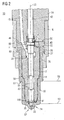
- FIG. 2 shows a cut view of an exemplary embodiment of an injection nozzle system 10 adapted for injecting an alternative fuel such as pyrolysis oil into a combustion chamber.
- Injection nozzle system 10 includes a needle 12, a needle guide member 14, and a ceramic hood 30.
- Needle guide member 14 and ceramic hood 30 form a two- piece injector body.
- Ceramic hood 30 essentially surrounds needle guide member 14 with the exception of a collar 40 of needle guide member 14 at a nozzle holder side of injection nozzle system 10 and the associated nozzle holder side face 96 of needle guide member 14.
- ceramic hood 30 provides a blind hole partly enclosing a blind hole section 22 and comprises nozzle spray holes 24 in the wall of the blind hole.
- the wall of the blind hole are rotational symmetrical with respect to a longitudinal axis 23 of injection nozzle system 10, for example, the wall may be bell-shaped, shaped as a half-sphere, or a closed cylinder. Alternatively, the wall may not be rotational symmetrical, for example in the form of a cube that is open at one side.
- Needle guide member 14 includes nozzle holder side face 96 at a first end and a combustion zone face 95 at a second end.
- a needle guiding bore 19 extends from a first opening 64 in nozzle holder side face 96 to a second opening 66 in combustion zone face 95 of needle guide member 14 (see Fig. 3 ).
- FIG. 3 for a detailed view of the front end of the exemplary injection nozzle system 10 of Fig. 2 .
- a sealing ring recess 102 extends around second opening 66 on combustion zone face 95 of needle guide member 14. Sealing ring recess 102 is configured as a circumferential groove. Alternatively, sealing ring recess 102 may be configured triangular, quadrangular, pentagonal, or hexagonal (etc).
- an inner side face 104 of sealing ring recess 102 may extend circumferentially around a centre point of second opening 66 in a distance within the range of 1.5 mm to 3 mm
- a sealing ring 100 is arranged in sealing ring recess 102 that is configured to hold sealing ring 100 for providing a first sealing between sealing ring recess 102 , sealing ring 100, and sealing face 90 of ceramic hood 30 in a mounted state of injection nozzle system 10 as is described in greater detail later on.
- second sealing is provided between sealing ring recess 102, sealing ring 100 and an outer section of sealing face 90.
- sealing ring 100 may be made of a material that resists the chemical corrosive and mechanical abrasive attack of alternative fuels.
- sealing ring 100 may be made of perfluoroelastomer.
- sealing ring 100 may be formed as an o-ring.
- sealing ring recess 102 comprises an inner side face 104, a ground face 106, and an outer side face 108.
- a height of the inner side face 104 may be greater than a height of the outer side face 108 as shown in the configuration of Fig. 3 .
- Combustion zone face 95 of needle guide member 14 includes a sealing face section 94.
- Sealing face section 94 extends between second opening 66 and sealing ring recess 102.
- sealing face section 94 may be configured to annularly extend between second opening 66 and sealing ring recess 102.
- sealing face section 94 may, for example, have an inner annular circumference transitions into second opening 66, and an outer circumference transitions into sealing ring recess 102 that may be, for example, triangular, quadrangular, pentagonal, or hexagonal shaped (etc.).
- sealing face section 94 of needle guide member 14 and sealing face 90 of ceramic hood 30 are configured to provide a second sealing radial within the first sealing in a mounted state of injection nozzle system 10. Specifically, second sealing is provided between sealing face section 94 and an inner section of sealing face 90.
- Combustion zone face 95 of needle guide member 14 further includes a leakage zone face section 110 that radially extends outside of sealing ring recess 102.
- leakage zone face section 110 may be configured to annularly extend outside of sealing ring recess 102.
- Leakage zone face section 110 is at least partially axially displaced in direction of nozzle holder side face 96 with respect to sealing face section 94, for example, due to height difference between inner side face 104 and outer side face 108 of sealing ring recess 102. Additionally or alternatively, leakage zone face section 110 may extend at least partially at a tilt angle with respect to sealing face section 94 within the range of 20° to 60°. It is noted that too sharp transitions may be avoided to smoothen the stress curve of needle guide member 14 at the injection side.
- Leakage zone face section 110 of needle guide member 14 and leakage zone face 112 of ceramic hood 30 are at least partially spaced from each other to form at least one leakage channel 114 for providing a leakage zone.
- a minimum clearance between leakage zone face 112 of ceramic hood 30 and leakage zone face section 110 of needle guide member 14 may be within the range of 0.2 mm to 0.4 mm.
- Leakage channel 114 is configured to guide leaking fuel from the second opening 66 entering the sealing ring recess 102 away to a pressure relief path 76 in a gap between needle guide member 14 and ceramic hood 30.
- Leakage zone face 112 of ceramic hood 30 extends radially outside of the sealing face 90 of ceramic hood 30. Specifically, leakage zone face 112 extends radially outside of an outer section of sealing face 90. For example, leakage zone face 112 may be configured to annularly extend radially outside of the outer section of the sealing face 90 of the ceramic hood 30
- Leakage zone face section 110 of needle guide member 14 and/or leakage zone face 112 of ceramic hood 30 may comprise one or more bars (not shown) extending, for example, radially outward.
- leakage zone face 112 of ceramic hood 30 is at least partially axially displaced in direction away from the nozzle holder 18 with respect to sealing face 90 of the ceramic hood 30. Additionally or alternatively, leakage zone face 112 of the ceramic hood 30 may extend at least partially at a tilt angle with respect to the sealing face 90 of the ceramic hood 30 within the range of 20° to 60° as shown in Fig. 3 . As noted before, too sharp transitions may be avoided to smoothen the stress curve of ceramic hood 30.
- two blind holes 49 may be provided in needle guide member 14 to hold bolts that ensure the proper relative position between needle guide member 14 and nozzle holder 18.
- needle 12 may be positioned in a needle guiding bore 19 of needle guide member 14. Needle 12 is movable along needle guiding bore 19. Needle 12 is guided by needle guide member 14 between a fuel injecting (open) state and a sealed (closed) state of injection nozzle system 10. The sealed state is shown in Fig. 1 .
- a mount 16 interacts with a nozzle holder 18, for example, via a thread connection (not shown).
- Mount 16 is configured to pull ceramic hood 30 towards nozzle holder 18.
- mount 16 may be a one-sided threaded nut such as a sleeve nut.
- mount 16 acts onto a mount contact face 27 of a collar 38 of ceramic hood 30.
- ceramic hood 30 contacts sealing ring 100 and needle guide member 14 at first at a first sealing zone 29 (as described above in connection with the first and the second sealing) and then at another sealing zone 31 at the nozzle holder side of injection nozzle system 10.
- Collar 40 of needle guide member 14 extends between collar 38 of ceramic hood 30 and nozzle holder 18. Applying a force onto collar 40 via collar 38 towards nozzle holder 18 allows forming a seal by tightly contacting opposing surfaces of needle guide member 14 and nozzle holder 18.
- sealing ring 100 is compressed between sealing ring recess 102 and sealing face 90 of ceramic hood 30 (see Fig. 3 ), thereby, forming a first sealing between needle guide member 14 and ceramic hood 30.
- sealing face section 94 of needle guide member 14 tightly contacts sealing face 90 of ceramic hood 30, thereby, forming a second sealing.
- Nozzle holder 18 is configured to interact with injection nozzle system 10 adapted for injecting fuel into a combustion chamber.
- nozzle holder 18 or a pump control system may include elements configured to open and/or close a valve that is formed at the injection side of injection nozzle system 10.
- the valve for example, may comprise a valve seat 44 of needle guide member 14 and the tip section of needle 12.
- nozzle holder 18 To operate the valve, nozzle holder 18 provides a force via a stud 42 onto needle 12 that counteracts the force onto needle 12 caused by the supplied pressurized fuel.
- a spring (not shown) may provide the force that acts via stud 42 onto needle 12 to close the valve by pressing needle 12 onto valve seat 44 thereby sealing an opening of valve seat 44.
- the force may be applied by a pressurized hydraulic system (not shown).
- Needle guiding bore 19 is shaped to form a high pressure fuel chamber 20 between needle 12 and needle guide member 14.
- High pressure fuel chamber 20 may be located close to the nozzle holder side of injection nozzle system 10, for example within the first third of the injection nozzle system 10.
- High pressure fuel chamber 20 is connected via, for example, one, two or more high pressure supply bores 46 (for example, two high pressure supply bores are shown in the top view of needle guide member 14 of Fig. 4 ) with corresponding high pressure supply conduits 48 of nozzle holder 18.
- High pressure supply conduits 48 is connected with sources of pressurized fluids, for example, the alternative fuel and/or additives that are usually provided by an injection pump system.
- Needle guide member 14 may be dimensioned such that it does not deform when fuels under high pressure are supplied into high pressure supply bores 46, high pressure fuel chamber 20, and needle guiding bore 19.
- high pressure supply bores 46 extend at a steep angle with respect to longitudinal axis 23 of injection nozzle system 10.
- high pressure supply bores 46 may extend at an angle larger than 20° for example, 25°,30°, 35° or 40°with respect to longitudinal axis 23.
- high pressure fuel chamber 20 is close to the nozzle holder side of injection nozzle system 10.
- high pressure fuel chamber 20 may be positioned within the nozzle holder half next to nozzle holder 18, for example, at about one third or one fourth of the length of needle guide member 14.
- the position of high pressure fuel chamber 20 may be about 20% of the length of needle guide member 14.
- a pressure relief path 76 is constituted of a drainage 70, a gap between ceramic hood 30 and needle guide member 14, and at least one leakage channel 114.
- injection nozzle system 10 results further in a short first needle guiding section 80 at the nozzle holder side of injection nozzle system 10.
- needle 12 and in particular a needle collar 50 provides a seal for the pressurized fuel in high pressure fuel chamber 20 in direction of nozzle holder 18.
- first needle guiding section 80 and therefore of collar 50 may be restricted in the configuration of the two-piece injector body, the leakage through the seal towards nozzle holder 18 is slightly increased compared to a longer needle guiding section.
- an increased leakage may have the advantage that a steady leaking flow of the fuel may be ensured and thereby solidification of the fuel in an outer drainage line (not shown) may be avoided, specifically for the case that the internal combustion engine is not operated and, for example, has cooled down.
- a second needle guiding section 82 at the injection side of needle 12 may be provided to assist the centering of needle 12 on valve seat 44.
- needle 12 may contact needle guide member 14 at first needle guiding section 80 and second needle guiding section 82 and in the sealed valve state additionally at valve seat 44.
- Other embodiments may have only a single needle guiding section and a more centralized high pressure.
- needle guiding bore 19 and needle 12 are further configured to provide a high pressure fuel path from high pressure fuel chamber 20 to valve seat 44.
- the high pressure fuel path accordingly passes through second needle guiding section 82, which, for example, may be formed by two, three or more, for example planes or ridges contacting the wall of needle guiding bore 19 and having fuel channels 84 in between.
- second needle guiding section 82 which, for example, may be formed by two, three or more, for example planes or ridges contacting the wall of needle guiding bore 19 and having fuel channels 84 in between.
- the opening of valve seat 44 of needle guide member 14 may be sealed by the tip of needle 12 thereby controlling the injection of the alternative fuel.
- blind hole section 22 may be enclosed by ceramic hood 30 (with the exception of the opening of the blind hole).
- Blind hole section 22 may be fluidly connected via spray holes 24 to the outside of ceramic hood 30, and, in the mounted state of injection nozzle system 10, to the inside of the combustion chamber (cylinder head).
- a wall of a cylinder head is indicated by dashed lines 56 and 58.
- a high pressure seal may be formed between needle guide member 14 and ceramic hood 30, namely above described first sealing and the second sealing.
- pressurized fuel may only leave blind hole section 22 through spray holes 24 and the fuel may eject with high speed through spray holes 24.
- the high corrosive and abrasive feature of the alternative fuel may be supplemented with a high mechanical abrasion of the fast flowing alternative fuel and the small sized particles carried along with it.
- Ceramic hood 30 being made of engineering ceramics such as zirconium oxide or aluminum oxide may be configured to resist the chemical corrosive and mechanical abrasive attack.
- the configuration of the two-piece injector body may allow replacing only ceramic hood 30 while keeping needle 12 and needle guide member 14 unchanged.
- injection nozzle system 10 reaches through the wall of the cylinder head.
- a cylinder head contact face 60 of ceramic hood 30 contacts the wall of the cylinder head or a bushing (for example a stainless steel sleeve) inserted into a hole of the wall of the cylinder head. Accordingly, only an end face 62 of ceramic hood 30 that includes spray holes 24 may be exposed to the inside of the combustion chamber and may experience directly the heat and pressure caused by the combustion process in the combustion chamber.
- using an engineering ceramic for ceramic hood 30 may provide thermal insulation of injection nozzle system 10 from heat generated in the combustion chamber.
- the use of a ceramic hood may avoid the necessity of a cooling system adapted for cooling injection nozzle system 10. This may in particular be the case for alternative fuels, which are supplied at a relatively low temperature of about 60 °C in contrast to HFO supplied at 150 °C.
- Ceramic hood 30 is a separate part with spray holes 24 having a diameter of, for example, about 0.7 to 0.8 mm.
- the specific shape of spray holes 24 may be essential for the injection process. This may be in particular the case for conventional pump-line-nozzle injection systems, which require an initial adjustment of the pump parameters for a specific spray hole configuration.
- changes of the shape of spray holes 24 due to abrasive and corrosive wear may affect directly the fuel distribution in the combustion chamber and, therefore, the combustion process such as efficiency and soot formation because an adjustment of the pump parameters may usually not be possible.
- common rail injection systems may be sensitive for geometrical changes due to abrasive and corrosive wear of the shape of spray holes 24.
- ceramic hood 30 is mounted as a separate part and encloses essentially the complete needle guide member 14 with the exception of one face (for contacting the nozzle holder) and collar 40.
- ceramic hood 30 is not in contact with needle guide member 14 with the exception that there may be contact at first sealing zone 29 (with above mentioned first and second sealing), and another sealing zone 31 in the mounted state.
- the surface of ceramic hood 30 may, for example, be grinded.
- ceramic hood 30 may be mounted under tensile stress between first sealing zone 29 and another sealing zone 31.
- the length between a sealing face 90 and a nozzle holder side face 92 of ceramic hood 30 may be - in the unmounted state - shorter than the length between sealing face section 94 and a nozzle holder side face 96 of needle guide member 14 by a predefined amount.
- the predefined amount may be chosen such that when ceramic hood 30 is pulled towards nozzle holder 18 and is in contact with nozzle holder side face 96 of needle guide member 14, the tensile force within ceramic hood 30 may be preferably still in the range of elastic behavior but may provide a sufficient sealing between ceramic hood 30 and needle guide member 14 and needle guide member 14 and nozzle holder 18.
- the difference in length may be 0.05 mm or less or 0.03 mm or less, depending on the type of ceramic material and/or the thickness of the wall of the ceramic hood 30.
- a specific pair of a hood and needle guide member may be selected from a set of pre-manufactured hoods and needle guide members, thereby allowing a lower precision during manufacture.
- ceramic hood 30 may comprise, at the nozzle holder side of ceramic hood 30, collar 38 that may have a nozzle holder side face 92 and mount contact face 27 on opposite sides. Faces 92 and 27 may extend essentially in a radial direction with respect to longitudinal axis 23. Alternatively, one or both faces 92 and 27 may be configured to have some tilt at a predefined angle with respect to the longitudinal direction. Moreover, ceramic hood 30 may comprise, at the injection side of ceramic hood 30, sealing face 90 on an inner surface of ceramic hood 30 and sealing face 90 may have an opening and extend essentially orthogonal, in other words, in a radial direction, with respect to longitudinal axis 23.
- ceramic hood 30 may form blind hole section 22 of the inner chamber at the injection side of ceramic hood 30.
- Blind hole section 22 may be fluidly connected to the inside of ceramic hood 30, for example, via the opening in sealing face 90, and to an outside of ceramic hood 30 via a plurality of nozzle spray holes 24.
- the blind hole section 22 being a part of the inner chamber formed by ceramic hood 30 is fluidly connected with the remaining section (volume) of the inner chamber.
- the fluid connection between the blind hole section 22 and the remaining section passes through second opening 66.
- ceramic hood 30 may comprise a region in which the radial extension of ceramic hood 30 is changed. There, an inclined face 98 on the inside may extend at an angle smaller than 50°, for example, 40°, 35°, 30°, 25°, 20°, or 15°, with respect to longitudinal axis 23 for providing a smooth change of geometry in that region. In that central region, ceramic hood 30 may further comprise cylinder head contact face 60 on the outer surface of ceramic hood 30 extending essentially orthogonal with respect to longitudinal axis 23 (or having a predefined inclination therewith).
- Inclined face 98 provides a specific stress distribution in the mounted states, in other words, before being mounted to the cylinder head and once cylinder head contact face 60 being in contact with, for example, the cylinder head.
- ceramic hood 30 is partially cylindrically shaped, and at least one of sealing face 90, mount contact face 27, nozzle holder side face 92 and cylinder head contact face 60 may be ring-shaped.
- Sealing face 90 may have a high quality, for example plan-parallel surface shape to allow the required sealing performance in the mounted state and the applied high fuel pressures.
- sealing face 90 may be configured to form a high pressure sealing with sealing face section 94 of needle guide member 14, when a force is applied onto mount contact face 27 in direction of the nozzle holder side of ceramic hood 30.
- a distance between sealing face 90 and nozzle holder side face 92 of ceramic hood 30 may be less than a distance between corresponding faces 94, 96 of the needle guide member 14, thereby providing a tensile stress within ceramic hood 30 in a mounted state of injection nozzle system 10.
- drainage 70 may provide together with a gap between needle guide member 14 and ceramic hood 30, and the at least one leakage channel 114, pressure relief path 76 (shown in Fig. 2 ).
- maximum pressures in the range of, for example, about 1500 bar to 1700 bar may occur within injection nozzle system 10. If a proper high pressure seal may be maintained in first sealing zone 29 during operation, only the small inside surface of the blind hole forming blind hole section 22 of ceramic hood 30 is subject to those pressures.
- those pressures of the pressurized fuel may act onto the large inside surface of ceramic hood 30.
- the relevant surface subject to the maximum pressure along longitudinal axis 23 may correspond essentially to the diameter of ceramic hood 30 (without collar 38). The resulting large force may then destroy ceramic hood 30 if no countermeasures are taken.
- Injection nozzle system 10 therefore may provide pressure relief path 76 to release any leaking fuel along an unpressurized path.
- any fuel leaking through first sealing zone 29 may pass through the gap between needle guide member 14 and ceramic hood 30 in direction of nozzle holder 18.
- drainage 70 may guide the fuel towards collar 50 of needle 12, where pressure relief path 76 may combine with a leakage path through first needle guiding section 80.
- pressure relief path 76 may allow a controlled removal of the fuel.
- the herein disclosed concept of a pressure relief path may also be applied with two-piece injector bodies that use non-ceramic hoods.
- the configuration of the two-piece injector body may also allow an additional implementation of a cooling system to provide cooling and prevent any damage to the injection nozzle system.
- a cooling system may prevent, for example, damaging valve seat 44 or weakening the high pressure seal in first sealing zone 29 between needle guide member 14 and ceramic hood 30 in Fig. 2 .
- a cooling system may absorb leakage through first sealing zone 29 next to valve seat 44 and, therefore, may include additionally the functionality of a high pressure relief path to avoid destruction of ceramic hood 30 due to over pressure. In that case, a pressure relief path as discussed above in connection with Fig. 2 may not be required.
- materials for use with alternative fuels may have an increased corrosion resistance.
- the materials may be sufficiently resistant with respect to slow flowing fuels (reduced mechanical abrasion compared to the spray holes) and with respect to the chemical exposure to the acidity (in other words, to a low pH value) of, for example, alternative fuels.
- Exemplary materials for needle guide members and for needles include tempered tool steel and, in particular, austenitic steel, for example cobalt-chromium steel.
- austenitic steel for example cobalt-chromium steel.
- all or selected sections of the surfaces of the needles or needle guide members may be coated with diamond-like carbon (DLC).
- DLC diamond-like carbon
- Exemplary materials for the hoods may include engineering ceramics such as oxide ceramics and non-oxide ceramics or other ceramic materials that are resistant against corrosion and abrasion by for example acidic alternative fuels (or a combination of two or more of those materials).
- oxide ceramics may include aluminum oxide, magnesium oxide, aluminium titanate, titanium dioxide and zirconium dioxide (including, for example, partially stabilized (PSZ), fully stabilized (FSZ), and tetragonal zirconia polychristal (TSZ)).
- PSZ partially stabilized
- FSZ fully stabilized
- TSZ tetragonal zirconia polychristal
- non-oxide ceramics may include carbides and nitrides.
- Exemplary carbides include silicium carbide (SiC) (for example, recrystallized SiC, nitride bonded SiC, pressureless sintered SiC, silicon infiltrated SiC, hot pressed SiC, hot isostatically pressed SiC, liquid phase sintered SiC), boron carbide, and tungsten carbide.
- Exemplary nitrides include silicon nitride (SN) (for example, sintered SN, reaction-bonded SN, hot pressed SN), silicon oxy-nitride, aluminium nitride, boron nitride, and titanium nitride.
- the hood may also be made of the materials discussed above for the needle and/or the needle guiding member.
- one or more of the various faces which are shown in the drawings for the disclosed embodiments to extend in a radial extension, specifically faces 27 and 92, may include sections that extend at an angle of for example 5°, 10°, 15°, 20°, 25°, or 30° with respect to the radial direction (which is, for example, orthogonal to the longitudinal axis 23 shown in Fig. 2 ).
- Exemplary dimensions for an injection nozzle system disclosed herein may include a length of the hood and needle guide element of about 100 mm, an outer diameter of the hood of about 40 mm, a wall thickness of the ceramic hood of about 5 mm.
- the difference in length discussed above for the hood and the needle guide member in the unmounted state is, for example, 1/10.000 of the length of the hood.
- the ceramic hood stretches by several ten micrometer.
- the ceramic hood may generally also be shaped to extend at least partly over the collar, specifically beyond nozzle holder side face 96 onto the radial outside face of collar 40.
- a ceramic hood may only not cover the face of the needle guide element directed to the nozzle holder.
- a ceramic hood with a distance between the needle guide member contacting faces that is as large as possible to increase the effective length of the hood onto which the tensile stress may be distributed.
- the relative difference in the distance between the respective contact faces of the needle guide member and the ceramic hood may provide a predefined pretension of the ceramic hood and, therefore, a predefined sealing force.
- this relative difference may vary for optimal sealing.
- the herein disclosed relative difference in length may take also into consideration that the mounting of, for example, injection nozzle system 10 to the cylinder head may cause an additional stress onto, for example., ceramic hood 30 via cylinder head contact face 60, which may also affect the stress profile within ceramic hood 30.
- the disclosed injection nozzle systems may allow maintaining an outer shape of a conventional nozzle system.
- the disclosed nozzle systems may thereby simplify the modification of injection systems adapted for use with alternative fuels such as pyrolysis oil.
- the disclosed nozzle system may fulfill geometric boundary conditions of known nozzle system, thereby simplifying a replacement of a conventional nozzle system with the herein disclosed nozzle systems.
- internal combustion engine may refer to internal combustion engines which may be used as main or auxiliary engines of stationary power providing systems such as power plants for production of heat and/or electricity as well as in ships/vessels such as cruiser liners, cargo ships, container ships, and tankers.
- internal combustion engine as used herein is not specifically restricted and comprises any engine, in which the combustion of a fuel occurs with an oxidizer to produce high temperature and pressure gases, which are directly applied to a movable component of the engine, such as pistons or turbine blades, and move it over a distance thereby generating mechanical energy.
- internal combustion engine comprises piston engines and turbines, which can, for example, be operated with alternative fuels such as pyrolysis oil.
- Examples of such engines that are suitable for adaptation to alternative fuels include medium speed internal combustion diesel engines, like inline and V-type engines of the series M20, M25, M32, M43 manufactured by Caterpillar Motoren GmbH & Co. KG, Kiel, Germany, operated in a range of 500 to 1000 rpm.
- injection nozzle systems may comprise one or more features of a needle, a needle guide member comprising a bore configured for guiding the needle between a fuel injection state and a closed state of the injection nozzle system, and a nozzle hood, for example, a ceramic hood, surrounding essentially the needle guide member with the exception of a face of the needle guide member at a nozzle holder side of the injection nozzle system.
- the nozzle hood may comprise a blind hole and the inner chamber of the hood may comprise a blind hole section fluidly connected via an opening to a high pressure fuel path of the injection nozzle system and via a plurality of nozzle spray holes to an outside of the hood at an injection side of the injection nozzle system.
- the bore of the needle guide member may be configured to provide a high pressure chamber within an upper third of the needle guide member next to the nozzle holder side and a high pressure supply bore may be configured to connect the high pressure chamber with the face of the needle guide member at the nozzle holder side and to be inclined with respect to a longitudinal axis of the nozzle system at an angle greater than 20°.
- injection nozzle systems may further include, for example, one or more of the following features.
- the supply bore may be connected to the high pressure chamber at a position that is located at 35%, 30%, 25%, 20%, or 15% of the length of the needle guide member measured from the nozzle holder side.
- the high pressure supply bore may be inclined with respect to the longitudinal axis of the nozzle system at an angle greater than 25°, 30°, 35° or 40°
- a material thickness of the needle guide member around the high pressure supply bore and the bore may be configured to essentially not deform under the pressure of a supplied pressurized fuel during operation.
- the bore may comprise a first needle guiding section between the high pressure chamber and a collar of the needle.
- the length of first needle guiding section may be 30%, 20%, 15%, 10% or 5% of the extension of the needle guiding member along the longitudinal axis.
- the bore may comprise a second needle guiding section close to the injection side that is in interaction with the needle.
- the second needle guiding section may comprise regions in which the needle and the bore contact each other and regions that provide a passage for the pressurized fuel during operation.
- the second needle guiding section may be configured to assist centralizing needle on a valve seat of the needle guide member.
- a plurality of high pressure supply bores may be configured to supply one or more fluids to the high pressure chamber during operation.
- the needle guiding member may be configured to form a valve seat with an opening at the injection side, and the needle may be configured for sealing the opening of the valve seat.
- a nozzle hood may be configured to essentially surround the needle guide member with the exception of a face of the needle guide member at a nozzle holder side of the injection nozzle system, the nozzle hood comprising a blind hole such that a blind hole section of an inner chamber of the hood is fluidly connected, for example, via an opening, to a high pressure fuel path of the injection nozzle system and via a plurality of nozzle spray holes to an outside of the nozzle hood.
- the nozzle hood and the needle guide member may contact each other essentially only at a first sealing zone and at a second sealing zone and form a gap between the hood and the needle guide member and the gap may be limited by the first sealing zone and the second sealing zone, and the injection nozzle system may comprise a pressure relief path connecting the gap with an outside of the injection nozzle system at the nozzle holder side.
- the needle may comprise a collar at the nozzle holder side and the needle guide member may comprise a bore in which the needle is positioned and a drainage connecting the gap with the bore in a region of the collar of the needle.
- the needle guide member may comprise a collar, a pressure relief bore within the collar, and a channel formed on a face of the needle guide member at a nozzle holder side, the pressure relief bore connecting the gap with the channel and extending radially inwards.
- the channel may be a groove on the face of the needle guide member at the nozzle holder side.
- the needle guide member may comprise a channel formed on a surface of a collar of the needle guide member and extending from the gap to a central region of the face of the needle guide member at the nozzle holder side.
- the pressure relief path may be configured to provide a low pressure passage for fuel leaking through the first sealing zone during operation.
- the hood may be made of an engineering ceramic such as zirconium oxide or aluminium oxide.
- Injection nozzle systems may be configured such that the nozzle hood and the needle guide member contact each other essentially only at the first sealing zone and at the second sealing zone in the mounted state.
Landscapes
- Engineering & Computer Science (AREA)
- Chemical & Material Sciences (AREA)
- Combustion & Propulsion (AREA)
- Mechanical Engineering (AREA)
- General Engineering & Computer Science (AREA)
- Fuel-Injection Apparatus (AREA)
Abstract
Description
- The present disclosure generally relates to an injection nozzle system, and more particularly to an injection nozzle system including a ceramic hood.
- Recently, use of alternative fuels to power internal combustion engines is subject of ongoing interest. Alternative fuels include first generation biofuels (for example palm oil, canola oil, oils based on animal fat) and second generation biofuels (for example oils made of non food corps, waste biomass)
- Examples of second generation biofuel include "pyrolysis oils" obtained from the pyrolysis of, for example, wood or agricultural wastes, such as the stalks of wheat or corn, grass, wood, wood shavings, grapes, and sugar cane. In general, pyrolysis oil is predominantly produced by the "Fast Pyrolysis" technology, which comprises rapid pyrolysation of biomass in a fluidized bubbling sand bed reactor, wherein the solid heat-carrying medium is circulated and, therefore, the residence time of solids is well-controlled and high heating rates (up to 1000 °C/second) are obtained.
- As the chemical composition and/or the physical properties of alternative fuels can differ significantly from those of commonly used fuels such as diesel fuel, light fuel oil (LFO), and heavy fuel oil (HFO), care has to be taken when alternative fuels are used as substitutes.
- For example, use of alternative fuels in internal combustion engines affects in particular the supply of the alternative fuel to a combustion chamber. The supply path includes usually an injection pump systems and an injection nozzle system.
- For an injection nozzle system,
WO 2011/157375 discloses a two part injection nozzle system formed by a needle guide member and a ceramic hood to withstand alternative fuels. - The present disclosure is directed, at least in part, to improving or overcoming one or more aspects of the related prior art and particularly improving an injection nozzle system comprising a ceramic hood.
- According to an aspect of the present disclosure, a needle guide member configured to form an injection nozzle system together with a needle and a ceramic hood, may comprise a nozzle holder side face at a first end, the nozzle holder side face comprising a first opening; a combustion zone face at a second end, the combustion zone face comprising a second opening; a needle guiding bore extending through the needle guide member from the first opening to the second opening, the needle guiding bore being configured to guide the needle between a fuel injection state and a closed state of the injection nozzle system; and a sealing ring recess extending around the second opening on the combustion zone face.
- According to another aspect of the present disclosure, an injection nozzle system may comprise a needle, a needle guide member as exemplary disclosed herein; a ceramic hood configured to essentially surround the needle guide member with the exceptions of the nozzle holder side face of the needle guide member, the ceramic hood comprising a blind hole fluidly connected to the needle guiding bore via the second opening, and to an outside of the ceramic hood via a plurality of nozzle spray holes, and a sealing face surrounding the blind hole ; a sealing ring arranged in the sealing ring recess of the needle guide member; the sealing ring being made of perfluoroelastomer and/or being formed as an o-ring; a nozzle holder, wherein the needle guide member, and the ceramic hood are mounted onto the nozzle holder such that the first sealing is provided between the sealing ring recess of the needle guide member, the sealing ring , and an outer section of the sealing face of the ceramic hood, and the second sealing is provided between the sealing face section of the needle guide member and an inner section of the sealing face of the ceramic hood.
- Other features and aspects of this disclosure will be apparent from the following description and the accompanying drawings.
-
-
Fig. 1 shows a schematic block diagram of an exemplary internal combustion engine system; -
Fig. 2 shows a cut view of an exemplary injection nozzle system; -
Fig. 3 shows a cut view of a front end of the exemplary injection nozzle system ofFig. 2 ; and -
Fig. 4 shows a top view of an exemplary needle guide member of the injection nozzle system ofFig. 2 . - The following is a detailed description of exemplary embodiments of the present disclosure. The exemplary embodiments described therein and illustrated in the drawings are intended to teach the principles of the present disclosure, enabling those of ordinary skill in the art to implement and use the present disclosure in many different environments and for many different applications. Therefore, the exemplary embodiments are not intended to be, and should not be considered as, a limiting description of the scope of patent protection. Rather, the scope of patent protection shall be defined by the appended claims.
- The disclosure may be based in part on the realisation that improving a sealing between opposing faces of a needle guide member and a ceramic hood may help to reduce corrosive and abrasive effects of alternative fuels on the injection nozzle system.
- The disclosure may be further based in part on the realisation that improving the conveying of leaking fuel away from the location of leakage in the case that the sealing between the needle guide member and the ceramic hood cannot be completely achieved or is partly reduced during operation of the internal combustion engine. Conveying leaking fuel along desired channels and passages reduces may further reduce corrosive and abrasive effects of alternative fuel on the injection nozzle system.
- Accordingly, an injection nozzle system is disclosed, that may comprise a sealing ring arranged in a sealing ring recess of the needle guide member to improve the sealing between needle guide member and ceramic hood.
- In addition, a specific design configuration of opposing faces of the needle guide member and the ceramic hood may ensure that leaking fuel may be effectively guided away from the sealing ring recess.
-
Fig. 1 shows a non-limiting example of an internal combustion engine system with an injection nozzle system. The internal combustion engine system may include, for example, an engine with a cam injection pump for a conventional pump-line-nozzle injection or an engine with a common rail injection, which may be operated more flexible, for example, to adjust an injection pressure, a rail pressure, the injection timing, the number and type of injections (for example, pre- and post-injections). - The internal combustion engine system includes a reservoir 1 for an alternative fuel such as pyrolysis oil and an
internal combustion engine 5.Internal combustion engine 5 is configured to operate, for example, with a mixture of the pyrolysis oil with additives such as mineral oil, synthetic oil, natural oil, and/or a lubricant. Accordingly, the internal combustion engine system may optionally include one or more ofreservoirs inlet 4A of homogenizer 4 may be connected viacorresponding lines reservoirs -
Internal combustion engine 5 includes at least onefuel injection pump 5A connected via one ormore lines 4C with anoutlet 4B of homogenizer 4, at least onenozzle system 5B and at least onecombustion chamber 5C.Nozzle system 5B is supplied with the pressurized alternative fuel byfuel injection pump 5A and is configured to spray, for example, a mixture of the pyrolysis oil, the mineral oil, the synthetic oil, the natural oil, and/or the lubricant intocombustion chamber 5C. - The number of
fuel injection pumps 5A,nozzle systems 5B, andcombustion chambers 5C ofinternal combustion engine 5 is not specifically restricted. For example, a stationary or mobile power system may include for inline configurations 4, 6, 7, 8, or 9 combustion chambers with one or more associated fuel injection pumps and respective nozzle systems, while a V-configuration of an internal combustion engine may include, for example, 12 or 16 combustion chambers with one or more fuel injection pumps and respective nozzle systems. -
Fig. 2 shows a cut view of an exemplary embodiment of aninjection nozzle system 10 adapted for injecting an alternative fuel such as pyrolysis oil into a combustion chamber.Injection nozzle system 10 includes aneedle 12, aneedle guide member 14, and aceramic hood 30. -
Needle guide member 14 andceramic hood 30 form a two- piece injector body.Ceramic hood 30 essentially surroundsneedle guide member 14 with the exception of acollar 40 ofneedle guide member 14 at a nozzle holder side ofinjection nozzle system 10 and the associated nozzleholder side face 96 ofneedle guide member 14. At an injection side ofinjection nozzle system 10,ceramic hood 30 provides a blind hole partly enclosing ablind hole section 22 and comprisesnozzle spray holes 24 in the wall of the blind hole. - The wall of the blind hole are rotational symmetrical with respect to a
longitudinal axis 23 ofinjection nozzle system 10, for example, the wall may be bell-shaped, shaped as a half-sphere, or a closed cylinder. Alternatively, the wall may not be rotational symmetrical, for example in the form of a cube that is open at one side. -
Needle guide member 14 includes nozzleholder side face 96 at a first end and acombustion zone face 95 at a second end. A needle guidingbore 19 extends from a first opening 64 in nozzleholder side face 96 to asecond opening 66 incombustion zone face 95 of needle guide member 14 (seeFig. 3 ). - Referring now to
Fig. 3 for a detailed view of the front end of the exemplaryinjection nozzle system 10 ofFig. 2 . - A
sealing ring recess 102 extends aroundsecond opening 66 oncombustion zone face 95 ofneedle guide member 14.Sealing ring recess 102 is configured as a circumferential groove. Alternatively,sealing ring recess 102 may be configured triangular, quadrangular, pentagonal, or hexagonal (etc). - In some embodiments, an
inner side face 104 ofsealing ring recess 102 may extend circumferentially around a centre point ofsecond opening 66 in a distance within the range of 1.5 mm to 3 mm - A
sealing ring 100 is arranged in sealingring recess 102 that is configured to holdsealing ring 100 for providing a first sealing between sealingring recess 102 , sealingring 100, and sealingface 90 ofceramic hood 30 in a mounted state ofinjection nozzle system 10 as is described in greater detail later on. Specifically, second sealing is provided between sealing ring recess 102, sealingring 100 and an outer section of sealingface 90. - In addition,
sealing ring 100 may be made of a material that resists the chemical corrosive and mechanical abrasive attack of alternative fuels. For example, sealingring 100 may be made of perfluoroelastomer. In some embodiments, sealingring 100 may be formed as an o-ring. - In some embodiments, sealing ring recess 102 comprises an
inner side face 104, aground face 106, and anouter side face 108. A height of theinner side face 104 may be greater than a height of theouter side face 108 as shown in the configuration ofFig. 3 . -
Combustion zone face 95 ofneedle guide member 14 includes asealing face section 94.Sealing face section 94 extends between second opening 66 and sealing ring recess 102. For example, sealingface section 94 may be configured to annularly extend betweensecond opening 66 and sealingring recess 102. Alternatively, sealingface section 94 may, for example, have an inner annular circumference transitions intosecond opening 66, and an outer circumference transitions into sealingring recess 102 that may be, for example, triangular, quadrangular, pentagonal, or hexagonal shaped (etc.). - In addition, sealing
face section 94 ofneedle guide member 14 and sealingface 90 ofceramic hood 30 are configured to provide a second sealing radial within the first sealing in a mounted state ofinjection nozzle system 10. Specifically, second sealing is provided between sealingface section 94 and an inner section of sealingface 90. - Combustion zone face 95 of
needle guide member 14 further includes a leakagezone face section 110 that radially extends outside of sealingring recess 102. For example, leakagezone face section 110 may be configured to annularly extend outside of sealingring recess 102. - Leakage
zone face section 110 is at least partially axially displaced in direction of nozzle holder side face 96 with respect to sealingface section 94, for example, due to height difference betweeninner side face 104 andouter side face 108 of sealingring recess 102. Additionally or alternatively, leakagezone face section 110 may extend at least partially at a tilt angle with respect to sealingface section 94 within the range of 20° to 60°. It is noted that too sharp transitions may be avoided to smoothen the stress curve ofneedle guide member 14 at the injection side. - Leakage
zone face section 110 ofneedle guide member 14 andleakage zone face 112 ofceramic hood 30 are at least partially spaced from each other to form at least oneleakage channel 114 for providing a leakage zone. A minimum clearance betweenleakage zone face 112 ofceramic hood 30 and leakagezone face section 110 ofneedle guide member 14 may be within the range of 0.2 mm to 0.4 mm. -
Leakage channel 114 is configured to guide leaking fuel from thesecond opening 66 entering the sealingring recess 102 away to apressure relief path 76 in a gap betweenneedle guide member 14 andceramic hood 30. -
Leakage zone face 112 ofceramic hood 30 extends radially outside of the sealingface 90 ofceramic hood 30. Specifically,leakage zone face 112 extends radially outside of an outer section of sealingface 90. For example,leakage zone face 112 may be configured to annularly extend radially outside of the outer section of the sealingface 90 of theceramic hood 30 - Leakage
zone face section 110 ofneedle guide member 14 and/orleakage zone face 112 ofceramic hood 30 may comprise one or more bars (not shown) extending, for example, radially outward. - In some embodiments,
leakage zone face 112 ofceramic hood 30 is at least partially axially displaced in direction away from thenozzle holder 18 with respect to sealingface 90 of theceramic hood 30. Additionally or alternatively,leakage zone face 112 of theceramic hood 30 may extend at least partially at a tilt angle with respect to the sealingface 90 of theceramic hood 30 within the range of 20° to 60° as shown inFig. 3 . As noted before, too sharp transitions may be avoided to smoothen the stress curve ofceramic hood 30. - As shown in the top view of
needle guide member 14 ofFig. 4 , twoblind holes 49 may be provided inneedle guide member 14 to hold bolts that ensure the proper relative position betweenneedle guide member 14 andnozzle holder 18. - Turning again to
Fig. 2 ,needle 12 may be positioned in a needle guiding bore 19 ofneedle guide member 14.Needle 12 is movable alongneedle guiding bore 19.Needle 12 is guided byneedle guide member 14 between a fuel injecting (open) state and a sealed (closed) state ofinjection nozzle system 10. The sealed state is shown inFig. 1 . - A
mount 16 interacts with anozzle holder 18, for example, via a thread connection (not shown).Mount 16 is configured to pullceramic hood 30 towardsnozzle holder 18. For example, mount 16 may be a one-sided threaded nut such as a sleeve nut. In the embodiment ofFig. 1 , mount 16 acts onto amount contact face 27 of acollar 38 ofceramic hood 30. - If
mount 16 is moved towardsnozzle holder 18,ceramic hood 30contacts sealing ring 100 andneedle guide member 14 at first at a first sealing zone 29 (as described above in connection with the first and the second sealing) and then at another sealingzone 31 at the nozzle holder side ofinjection nozzle system 10.Collar 40 ofneedle guide member 14 extends betweencollar 38 ofceramic hood 30 andnozzle holder 18. Applying a force ontocollar 40 viacollar 38 towardsnozzle holder 18 allows forming a seal by tightly contacting opposing surfaces ofneedle guide member 14 andnozzle holder 18. Specifically, at the injection side ofinjection nozzle system 10, sealingring 100 is compressed between sealingring recess 102 and sealingface 90 of ceramic hood 30 (seeFig. 3 ), thereby, forming a first sealing betweenneedle guide member 14 andceramic hood 30. Furthermore, sealingface section 94 ofneedle guide member 14 tightlycontacts sealing face 90 ofceramic hood 30, thereby, forming a second sealing. -
Nozzle holder 18 is configured to interact withinjection nozzle system 10 adapted for injecting fuel into a combustion chamber. - Specifically,
nozzle holder 18 or a pump control system (not shown) may include elements configured to open and/or close a valve that is formed at the injection side ofinjection nozzle system 10. The valve, for example, may comprise avalve seat 44 ofneedle guide member 14 and the tip section ofneedle 12. - To operate the valve,
nozzle holder 18 provides a force via astud 42 ontoneedle 12 that counteracts the force ontoneedle 12 caused by the supplied pressurized fuel. In a conventional pump-line-nozzle injection system, for example, a spring (not shown) may provide the force that acts viastud 42 ontoneedle 12 to close the valve by pressingneedle 12 ontovalve seat 44 thereby sealing an opening ofvalve seat 44. In contrast, in a common rail injection pump system, the force may be applied by a pressurized hydraulic system (not shown). - Needle guiding bore 19 is shaped to form a high
pressure fuel chamber 20 betweenneedle 12 andneedle guide member 14. Highpressure fuel chamber 20 may be located close to the nozzle holder side ofinjection nozzle system 10, for example within the first third of theinjection nozzle system 10. Highpressure fuel chamber 20 is connected via, for example, one, two or more high pressure supply bores 46 (for example, two high pressure supply bores are shown in the top view ofneedle guide member 14 ofFig. 4 ) with corresponding highpressure supply conduits 48 ofnozzle holder 18. Highpressure supply conduits 48 is connected with sources of pressurized fluids, for example, the alternative fuel and/or additives that are usually provided by an injection pump system. -
Needle guide member 14 may be dimensioned such that it does not deform when fuels under high pressure are supplied into high pressure supply bores 46, highpressure fuel chamber 20, and needle guiding bore 19. - Together with the requirement to provide a similar or the same outer geometry of a conventional injection nozzle system, the configuration of the two-piece injector body may result in that high pressure supply bores 46 extend at a steep angle with respect to
longitudinal axis 23 ofinjection nozzle system 10. For example, high pressure supply bores 46 may extend at an angle larger than 20° for example, 25°,30°, 35° or 40°with respect tolongitudinal axis 23. - The two-piece injector body results further in that the position of high
pressure fuel chamber 20 is close to the nozzle holder side ofinjection nozzle system 10. For example, highpressure fuel chamber 20 may be positioned within the nozzle holder half next tonozzle holder 18, for example, at about one third or one fourth of the length ofneedle guide member 14. The position of highpressure fuel chamber 20 may be about 20% of the length ofneedle guide member 14. - A
pressure relief path 76 is constituted of a drainage 70, a gap betweenceramic hood 30 andneedle guide member 14, and at least oneleakage channel 114. - The above discussed requirement for the outer geometry of
injection nozzle system 10 results further in a short firstneedle guiding section 80 at the nozzle holder side ofinjection nozzle system 10. At the nozzle holder side ofinjection nozzle system 10,needle 12 and in particular aneedle collar 50 provides a seal for the pressurized fuel in highpressure fuel chamber 20 in direction ofnozzle holder 18. - As the length of first
needle guiding section 80 and therefore ofcollar 50 may be restricted in the configuration of the two-piece injector body, the leakage through the seal towardsnozzle holder 18 is slightly increased compared to a longer needle guiding section. In particular for alternative fuels such as pyrolysis oil, an increased leakage may have the advantage that a steady leaking flow of the fuel may be ensured and thereby solidification of the fuel in an outer drainage line (not shown) may be avoided, specifically for the case that the internal combustion engine is not operated and, for example, has cooled down. - A second
needle guiding section 82 at the injection side ofneedle 12 may be provided to assist the centering ofneedle 12 onvalve seat 44. In that case,needle 12 may contactneedle guide member 14 at firstneedle guiding section 80 and secondneedle guiding section 82 and in the sealed valve state additionally atvalve seat 44. - Other embodiments may have only a single needle guiding section and a more centralized high pressure.
- Referring to
Fig. 2 , needle guiding bore 19 andneedle 12 are further configured to provide a high pressure fuel path from highpressure fuel chamber 20 tovalve seat 44. The high pressure fuel path accordingly passes through secondneedle guiding section 82, which, for example, may be formed by two, three or more, for example planes or ridges contacting the wall of needle guiding bore 19 and havingfuel channels 84 in between. At the injection side, the opening ofvalve seat 44 ofneedle guide member 14 may be sealed by the tip ofneedle 12 thereby controlling the injection of the alternative fuel. - On the external side of the opening of
valve seat 44, in other words, outside needle guiding bore 19,blind hole section 22 may be enclosed by ceramic hood 30 (with the exception of the opening of the blind hole). -
Blind hole section 22 may be fluidly connected via spray holes 24 to the outside ofceramic hood 30, and, in the mounted state ofinjection nozzle system 10, to the inside of the combustion chamber (cylinder head). InFig. 2 , a wall of a cylinder head is indicated by dashedlines - In
injection nozzle system 10, a high pressure seal may be formed betweenneedle guide member 14 andceramic hood 30, namely above described first sealing and the second sealing. Thus, in the fuel injecting state ofinjection nozzle system 10, pressurized fuel may only leaveblind hole section 22 through spray holes 24 and the fuel may eject with high speed through spray holes 24. Accordingly the high corrosive and abrasive feature of the alternative fuel may be supplemented with a high mechanical abrasion of the fast flowing alternative fuel and the small sized particles carried along with it. -
Ceramic hood 30 being made of engineering ceramics such as zirconium oxide or aluminum oxide may be configured to resist the chemical corrosive and mechanical abrasive attack. - Moreover, if spray holes 24 are modified through the abrasion such that the operation of
injection nozzle system 10 does no longer fulfill its requirements, the configuration of the two-piece injector body may allow replacing onlyceramic hood 30 while keepingneedle 12 andneedle guide member 14 unchanged. - In the mounted state,
injection nozzle system 10 reaches through the wall of the cylinder head. A cylinderhead contact face 60 ofceramic hood 30 contacts the wall of the cylinder head or a bushing (for example a stainless steel sleeve) inserted into a hole of the wall of the cylinder head. Accordingly, only anend face 62 ofceramic hood 30 that includes spray holes 24 may be exposed to the inside of the combustion chamber and may experience directly the heat and pressure caused by the combustion process in the combustion chamber. - Thus, besides the above described resistance against abrasive and corrosive wear, using an engineering ceramic for
ceramic hood 30 may provide thermal insulation ofinjection nozzle system 10 from heat generated in the combustion chamber. - In some configuration, the use of a ceramic hood may avoid the necessity of a cooling system adapted for cooling
injection nozzle system 10. This may in particular be the case for alternative fuels, which are supplied at a relatively low temperature of about 60 °C in contrast to HFO supplied at 150 °C. -
Ceramic hood 30 is a separate part withspray holes 24 having a diameter of, for example, about 0.7 to 0.8 mm. The specific shape of spray holes 24 may be essential for the injection process. This may be in particular the case for conventional pump-line-nozzle injection systems, which require an initial adjustment of the pump parameters for a specific spray hole configuration. During operation, changes of the shape of spray holes 24 due to abrasive and corrosive wear may affect directly the fuel distribution in the combustion chamber and, therefore, the combustion process such as efficiency and soot formation because an adjustment of the pump parameters may usually not be possible. Despite its larger flexibility in the injection process, also common rail injection systems may be sensitive for geometrical changes due to abrasive and corrosive wear of the shape of spray holes 24. - In contrast to a ceramic coating,
ceramic hood 30 is mounted as a separate part and encloses essentially the completeneedle guide member 14 with the exception of one face (for contacting the nozzle holder) andcollar 40. In general,ceramic hood 30 is not in contact withneedle guide member 14 with the exception that there may be contact at first sealing zone 29 (with above mentioned first and second sealing), and another sealingzone 31 in the mounted state. The surface ofceramic hood 30 may, for example, be grinded. - To provide the high pressure seal at first sealing zone 29 and to also ensure the sealed mounting of
needle guide member 14 tonozzle holder 18,ceramic hood 30 may be mounted under tensile stress between first sealing zone 29 and another sealingzone 31. To provide the tension in the mounted state, the length between a sealingface 90 and a nozzle holder side face 92 ofceramic hood 30 may be - in the unmounted state - shorter than the length between sealingface section 94 and a nozzle holder side face 96 ofneedle guide member 14 by a predefined amount. - The predefined amount may be chosen such that when
ceramic hood 30 is pulled towardsnozzle holder 18 and is in contact with nozzle holder side face 96 ofneedle guide member 14, the tensile force withinceramic hood 30 may be preferably still in the range of elastic behavior but may provide a sufficient sealing betweenceramic hood 30 andneedle guide member 14 andneedle guide member 14 andnozzle holder 18. - For example, the difference in length may be 0.05 mm or less or 0.03 mm or less, depending on the type of ceramic material and/or the thickness of the wall of the
ceramic hood 30. To provide such a specific difference in length, besides high precision manufacturing, a specific pair of a hood and needle guide member may be selected from a set of pre-manufactured hoods and needle guide members, thereby allowing a lower precision during manufacture. - To summarize the exemplary configuration of
ceramic hood 30 shown inFig. 2 ,ceramic hood 30 may comprise, at the nozzle holder side ofceramic hood 30,collar 38 that may have a nozzleholder side face 92 andmount contact face 27 on opposite sides.Faces longitudinal axis 23. Alternatively, one or both faces 92 and 27 may be configured to have some tilt at a predefined angle with respect to the longitudinal direction. Moreover,ceramic hood 30 may comprise, at the injection side ofceramic hood 30, sealingface 90 on an inner surface ofceramic hood 30 and sealingface 90 may have an opening and extend essentially orthogonal, in other words, in a radial direction, with respect tolongitudinal axis 23. Moreover,ceramic hood 30 may formblind hole section 22 of the inner chamber at the injection side ofceramic hood 30.Blind hole section 22 may be fluidly connected to the inside ofceramic hood 30, for example, via the opening in sealingface 90, and to an outside ofceramic hood 30 via a plurality of nozzle spray holes 24. - The
blind hole section 22 being a part of the inner chamber formed byceramic hood 30 is fluidly connected with the remaining section (volume) of the inner chamber. The fluid connection between theblind hole section 22 and the remaining section passes throughsecond opening 66. - Moreover,
ceramic hood 30 may comprise a region in which the radial extension ofceramic hood 30 is changed. There, aninclined face 98 on the inside may extend at an angle smaller than 50°, for example, 40°, 35°, 30°, 25°, 20°, or 15°, with respect tolongitudinal axis 23 for providing a smooth change of geometry in that region. In that central region,ceramic hood 30 may further comprise cylinderhead contact face 60 on the outer surface ofceramic hood 30 extending essentially orthogonal with respect to longitudinal axis 23 (or having a predefined inclination therewith). -
Inclined face 98 provides a specific stress distribution in the mounted states, in other words, before being mounted to the cylinder head and once cylinderhead contact face 60 being in contact with, for example, the cylinder head. - In the embodiment of
Fig. 2 ,ceramic hood 30 is partially cylindrically shaped, and at least one of sealingface 90,mount contact face 27, nozzleholder side face 92 and cylinderhead contact face 60 may be ring-shaped. - Sealing
face 90 may have a high quality, for example plan-parallel surface shape to allow the required sealing performance in the mounted state and the applied high fuel pressures. - To further make
ceramic hood 30 resistant against tensile stress, smooth transitions at diameter changes may be provided. For example, at the diameter change in the central part of ceramic nozzle close to cylinderhead contact face 60,inclined face 98 may provide a smooth transmission of force withinceramic hood 30 and, thereby, smoothen the stress profile. - In
injection nozzle system 10, sealingface 90 may be configured to form a high pressure sealing with sealingface section 94 ofneedle guide member 14, when a force is applied ontomount contact face 27 in direction of the nozzle holder side ofceramic hood 30. In an unmounted state ofinjection nozzle system 10, a distance between sealingface 90 and nozzle holder side face 92 ofceramic hood 30 may be less than a distance between corresponding faces 94, 96 of theneedle guide member 14, thereby providing a tensile stress withinceramic hood 30 in a mounted state ofinjection nozzle system 10. - As mentioned above, drainage 70 may provide together with a gap between
needle guide member 14 andceramic hood 30, and the at least oneleakage channel 114, pressure relief path 76 (shown inFig. 2 ). During operation of, for example, pump-line-nozzle injection, maximum pressures in the range of, for example, about 1500 bar to 1700 bar may occur withininjection nozzle system 10. If a proper high pressure seal may be maintained in first sealing zone 29 during operation, only the small inside surface of the blind hole formingblind hole section 22 ofceramic hood 30 is subject to those pressures. - However, in the case of leakage of high pressure fuel through first sealing zone 29, those pressures of the pressurized fuel may act onto the large inside surface of
ceramic hood 30. For example, the relevant surface subject to the maximum pressure alonglongitudinal axis 23 may correspond essentially to the diameter of ceramic hood 30 (without collar 38). The resulting large force may then destroyceramic hood 30 if no countermeasures are taken. -
Injection nozzle system 10 therefore may providepressure relief path 76 to release any leaking fuel along an unpressurized path. Specifically, any fuel leaking through first sealing zone 29 may pass through the gap betweenneedle guide member 14 andceramic hood 30 in direction ofnozzle holder 18. In the region ofcollar 38, drainage 70 may guide the fuel towardscollar 50 ofneedle 12, wherepressure relief path 76 may combine with a leakage path through firstneedle guiding section 80. Thus,pressure relief path 76 may allow a controlled removal of the fuel. - The herein disclosed concept of a pressure relief path may also be applied with two-piece injector bodies that use non-ceramic hoods.
- Although the above described ceramic hood concept may sufficiently insulate the nozzle system from the high temperatures of the combustion chamber, the configuration of the two-piece injector body may also allow an additional implementation of a cooling system to provide cooling and prevent any damage to the injection nozzle system. Such cooling may prevent, for example,
damaging valve seat 44 or weakening the high pressure seal in first sealing zone 29 betweenneedle guide member 14 andceramic hood 30 inFig. 2 . - In addition, a cooling system may absorb leakage through first sealing zone 29 next to
valve seat 44 and, therefore, may include additionally the functionality of a high pressure relief path to avoid destruction ofceramic hood 30 due to over pressure. In that case, a pressure relief path as discussed above in connection withFig. 2 may not be required. - For the various injection nozzle systems disclosed herein, materials for use with alternative fuels may have an increased corrosion resistance. For the needle guide members and the needles, the materials may be sufficiently resistant with respect to slow flowing fuels (reduced mechanical abrasion compared to the spray holes) and with respect to the chemical exposure to the acidity (in other words, to a low pH value) of, for example, alternative fuels.
- Exemplary materials for needle guide members and for needles include tempered tool steel and, in particular, austenitic steel, for example cobalt-chromium steel. In addition, all or selected sections of the surfaces of the needles or needle guide members may be coated with diamond-like carbon (DLC).
- Exemplary materials for the hoods may include engineering ceramics such as oxide ceramics and non-oxide ceramics or other ceramic materials that are resistant against corrosion and abrasion by for example acidic alternative fuels (or a combination of two or more of those materials).
- Examples for oxide ceramics may include aluminum oxide, magnesium oxide, aluminium titanate, titanium dioxide and zirconium dioxide (including, for example, partially stabilized (PSZ), fully stabilized (FSZ), and tetragonal zirconia polychristal (TSZ)).
- Examples for non-oxide ceramics may include carbides and nitrides. Exemplary carbides include silicium carbide (SiC) (for example, recrystallized SiC, nitride bonded SiC, pressureless sintered SiC, silicon infiltrated SiC, hot pressed SiC, hot isostatically pressed SiC, liquid phase sintered SiC), boron carbide, and tungsten carbide. Exemplary nitrides include silicon nitride (SN) (for example, sintered SN, reaction-bonded SN, hot pressed SN), silicon oxy-nitride, aluminium nitride, boron nitride, and titanium nitride.
- In some embodiments, the hood may also be made of the materials discussed above for the needle and/or the needle guiding member.
- In some embodiments, one or more of the various faces, which are shown in the drawings for the disclosed embodiments to extend in a radial extension, specifically faces 27 and 92, may include sections that extend at an angle of for example 5°, 10°, 15°, 20°, 25°, or 30° with respect to the radial direction (which is, for example, orthogonal to the
longitudinal axis 23 shown inFig. 2 ). - Exemplary dimensions for an injection nozzle system disclosed herein may include a length of the hood and needle guide element of about 100 mm, an outer diameter of the hood of about 40 mm, a wall thickness of the ceramic hood of about 5 mm. The difference in length discussed above for the hood and the needle guide member in the unmounted state is, for example, 1/10.000 of the length of the hood. In this example, the ceramic hood stretches by several ten micrometer.
- Although the figures show a hood configuration that does not surround the collar of the needle guide element, the ceramic hood may generally also be shaped to extend at least partly over the collar, specifically beyond nozzle holder side face 96 onto the radial outside face of
collar 40. For example, a ceramic hood may only not cover the face of the needle guide element directed to the nozzle holder. - In general, it may be advantageous to provide a ceramic hood with a distance between the needle guide member contacting faces that is as large as possible to increase the effective length of the hood onto which the tensile stress may be distributed.
- In general, the relative difference in the distance between the respective contact faces of the needle guide member and the ceramic hood may provide a predefined pretension of the ceramic hood and, therefore, a predefined sealing force. Depending on, for example the type of the material, and the thickness of the ceramic hood, this relative difference may vary for optimal sealing. The herein disclosed relative difference in length may take also into consideration that the mounting of, for example,
injection nozzle system 10 to the cylinder head may cause an additional stress onto, for example.,ceramic hood 30 via cylinderhead contact face 60, which may also affect the stress profile withinceramic hood 30. - Although the drawings show primarily rotational symmetric configurations of the outer shape of the injection nozzle systems and therefore needle guiding elements and hoods, also other shapes such as square or oval shapes may be in general be provided.
- The disclosed injection nozzle systems may allow maintaining an outer shape of a conventional nozzle system. Thus, the disclosed nozzle systems may thereby simplify the modification of injection systems adapted for use with alternative fuels such as pyrolysis oil. Moreover, the disclosed nozzle system may fulfill geometric boundary conditions of known nozzle system, thereby simplifying a replacement of a conventional nozzle system with the herein disclosed nozzle systems.
- Herein, the term "internal combustion engine" may refer to internal combustion engines which may be used as main or auxiliary engines of stationary power providing systems such as power plants for production of heat and/or electricity as well as in ships/vessels such as cruiser liners, cargo ships, container ships, and tankers.
- In addition, the term "internal combustion engine" as used herein is not specifically restricted and comprises any engine, in which the combustion of a fuel occurs with an oxidizer to produce high temperature and pressure gases, which are directly applied to a movable component of the engine, such as pistons or turbine blades, and move it over a distance thereby generating mechanical energy. Thus, as used herein, the term "internal combustion engine" comprises piston engines and turbines, which can, for example, be operated with alternative fuels such as pyrolysis oil.
- Examples of such engines that are suitable for adaptation to alternative fuels include medium speed internal combustion diesel engines, like inline and V-type engines of the series M20, M25, M32, M43 manufactured by Caterpillar Motoren GmbH & Co. KG, Kiel, Germany, operated in a range of 500 to 1000 rpm.
- In some embodiments, injection nozzle systems may comprise one or more features of a needle, a needle guide member comprising a bore configured for guiding the needle between a fuel injection state and a closed state of the injection nozzle system, and a nozzle hood, for example, a ceramic hood, surrounding essentially the needle guide member with the exception of a face of the needle guide member at a nozzle holder side of the injection nozzle system. The nozzle hood may comprise a blind hole and the inner chamber of the hood may comprise a blind hole section fluidly connected via an opening to a high pressure fuel path of the injection nozzle system and via a plurality of nozzle spray holes to an outside of the hood at an injection side of the injection nozzle system. The bore of the needle guide member may be configured to provide a high pressure chamber within an upper third of the needle guide member next to the nozzle holder side and a high pressure supply bore may be configured to connect the high pressure chamber with the face of the needle guide member at the nozzle holder side and to be inclined with respect to a longitudinal axis of the nozzle system at an angle greater than 20°.
- Alternative or additional implementations of injection nozzle systems may further include, for example, one or more of the following features.
- In injection nozzle systems, the supply bore may be connected to the high pressure chamber at a position that is located at 35%, 30%, 25%, 20%, or 15% of the length of the needle guide member measured from the nozzle holder side.
- In injection nozzle systems, the high pressure supply bore may be inclined with respect to the longitudinal axis of the nozzle system at an angle greater than 25°, 30°, 35° or 40°
- In injection nozzle systems, a material thickness of the needle guide member around the high pressure supply bore and the bore may be configured to essentially not deform under the pressure of a supplied pressurized fuel during operation.
- In injection nozzle systems, the bore may comprise a first needle guiding section between the high pressure chamber and a collar of the needle. The length of first needle guiding section may be 30%, 20%, 15%, 10% or 5% of the extension of the needle guiding member along the longitudinal axis.
- In injection nozzle systems, the bore may comprise a second needle guiding section close to the injection side that is in interaction with the needle. The second needle guiding section may comprise regions in which the needle and the bore contact each other and regions that provide a passage for the pressurized fuel during operation. The second needle guiding section may be configured to assist centralizing needle on a valve seat of the needle guide member.
- In injection nozzle systems, a plurality of high pressure supply bores may be configured to supply one or more fluids to the high pressure chamber during operation.
- In injection nozzle systems, the needle guiding member may be configured to form a valve seat with an opening at the injection side, and the needle may be configured for sealing the opening of the valve seat.
- In injection nozzle systems, a nozzle hood may be configured to essentially surround the needle guide member with the exception of a face of the needle guide member at a nozzle holder side of the injection nozzle system, the nozzle hood comprising a blind hole such that a blind hole section of an inner chamber of the hood is fluidly connected, for example, via an opening, to a high pressure fuel path of the injection nozzle system and via a plurality of nozzle spray holes to an outside of the nozzle hood. In the mounted state, the nozzle hood and the needle guide member may contact each other essentially only at a first sealing zone and at a second sealing zone and form a gap between the hood and the needle guide member and the gap may be limited by the first sealing zone and the second sealing zone, and the injection nozzle system may comprise a pressure relief path connecting the gap with an outside of the injection nozzle system at the nozzle holder side.
- In injection nozzle systems, the needle may comprise a collar at the nozzle holder side and the needle guide member may comprise a bore in which the needle is positioned and a drainage connecting the gap with the bore in a region of the collar of the needle.
- In injection nozzle systems, the needle guide member may comprise a collar, a pressure relief bore within the collar, and a channel formed on a face of the needle guide member at a nozzle holder side, the pressure relief bore connecting the gap with the channel and extending radially inwards.
- In injection nozzle systems, the channel may be a groove on the face of the needle guide member at the nozzle holder side.
- In injection nozzle systems, the needle guide member may comprise a channel formed on a surface of a collar of the needle guide member and extending from the gap to a central region of the face of the needle guide member at the nozzle holder side.
- The pressure relief path may be configured to provide a low pressure passage for fuel leaking through the first sealing zone during operation.
- In injection nozzle systems, the hood may be made of an engineering ceramic such as zirconium oxide or aluminium oxide.
- Injection nozzle systems may be configured such that the nozzle hood and the needle guide member contact each other essentially only at the first sealing zone and at the second sealing zone in the mounted state.
- Although the preferred embodiments of this invention have been described herein, improvements and modifications may be incorporated without departing from the scope of the following claims.
Claims (15)
- A needle guide member (14) configured to form an injection nozzle system (10) together with a needle (12) and a ceramic hood (30), the needle guide member (14) comprising:a nozzle holder side face (96) at a first end, the nozzle holder side face (96) comprising a first opening (64);a combustion zone face (95) at a second end, the combustion zone face (95) comprising a second opening (66);a needle guiding bore (19) extending through the needle guide member (14) from the first opening (64) to the second opening (66), the needle guiding bore (19) being configured to guide the needle (12) between a fuel injection state and a closed state of the injection nozzle system (10); anda sealing ring recess (102) extending around the second opening (66) on the combustion zone face (95).
- The needle guide member (14) of claim 1, wherein the sealing ring recess (102) is configured as a circumferential groove.
- The needle guide member (14) of claim 1 or 2, wherein the sealing ring recess (102) is configured to hold a sealing ring (100) for providing a first sealing between the sealing ring recess (102), the sealing ring (100), and a sealing face (90) of the ceramic hood (30) in a mounted state of the injection nozzle system (10).
- The needle guide member (14) of any one of claims 1 to 3, wherein the sealing ring recess (102) comprises an inner side face (104), a ground face (106), and an outer side face (108), and a height of the inner side face (104) is greater than a height of the outer side face (108).
- The needle guide member (14) of any one of claims 1 to 4, wherein the combustion zone face (95) further comprises a sealing face section (94) extending between the second opening (66) and the sealing ring recess (102), the sealing face section (94) being configured to provide a second sealing between sealing face section (94) and a sealing face (90) of the ceramic hood (30) in a mounted state of the injection nozzle system (10), the second sealing being radial within a first sealing.
- The needle guide member (14) of claim 5, wherein the sealing face section (94) is configured to annularly extend between the second opening (66) and the sealing ring recess (102).
- The needle guide member (14) of any one claims 1 to 6, wherein the combustion zone face (95) further comprises a leakage zone face section (110) extending from the sealing ring recess (102) radially outside, the leakage zone face section (110) being configured to form a part of a pressure relief path (76).
- The needle guide member (14) of claim 7, wherein the leakage zone face section (110) is configured to annularly extend radially outside of the sealing ring recess (102).
- The needle guide member of any one of claim 7 or 8, wherein the leakage zone face section (110) is at least partially axially displaced in direction of the nozzle holder side face (96) with respect to a sealing face section (94); and/or
the leakage zone face section (110) extends at least partially at a tilt angle with respect to the sealing face section (94) within the range of 20° to 60°. - The needle guide member (14) of any one of claims 1 to 9, wherein an inner side face (104) of the sealing ring recess (102) extends circumferentially around a centre point of the second opening (66) in a distance within the range of 1.5 mm to 3 mm.
- An injection nozzle system (10) comprising:a needle (12);a needle guide member (14) of any one of claims 1 to 10;a ceramic hood (30) configured to essentially surround the needle guide member (14) with the exceptions of the nozzle holder side face (96) of the needle guide member (14), the ceramic hood (30) comprising a blind hole (22) fluidly connected to the needle guiding bore (19) via the second opening (66), and to an outside of the ceramic hood (30) via a plurality of nozzle spray holes (24), and a sealing face (90) surrounding the blind hole (22);a sealing ring (100) arranged in the sealing ring recess (102) of the needle guide member (14), the sealing ring (100) being made of perfluoroelastomer and/or being formed as an o-ring;a nozzle holder (18), wherein the needle guide member (14), and the ceramic hood (30) are mounted onto the nozzle holder (18) such that the first sealing is provided between the sealing ring recess (102) of the needle guide member (14), the sealing ring (100), and an outer section of the sealing face (90) of the ceramic hood (30), and the second sealing is provided between the sealing face section (94) of the needle guide member (14) and an inner section of the sealing face (90) of the ceramic hood (30).
- The injection nozzle system (10) of claim 11, wherein at least one leakage channel (114) is provided between the leakage zone face section (110) of the needle guide member (14), and a leakage zone face (112) of the ceramic hood (30), the leakage zone face (112) of the ceramic hood (30) extends radially outside of the outer section of the sealing face (90) of the ceramic hood (30).
- The injection nozzle system of claim 11 or 12, wherein a leakage zone face (112) of the ceramic hood (30) is configured to annularly extend radially outside of the outer section of the sealing face (90) of the ceramic hood (30).
- The injection nozzle system of any one of claims 11 to 13, wherein a minimum clearance between a leakage zone face (112) of the ceramic hood (30) and the leakage zone face section (110) of the needle guide member (14) is within the range of 0.2 mm to 0.4 mm.
- The injection nozzle system of any one of claims 11 to 14, wherein a leakage zone face (112) of the ceramic hood (30) is at least partially axially displaced in direction away from the nozzle holder (18) with respect to the sealing face (90) of the ceramic hood (30); and/or
a leakage zone face (112) of the ceramic hood (30) extends at least partially at a tilt angle with respect to the sealing face (90) of the ceramic hood (30) within the range of 20° to 60°.
Priority Applications (1)
| Application Number | Priority Date | Filing Date | Title |
|---|---|---|---|
| EP12185144.8A EP2711535A1 (en) | 2012-09-20 | 2012-09-20 | Sealed two piece injector |
Applications Claiming Priority (1)
| Application Number | Priority Date | Filing Date | Title |
|---|---|---|---|
| EP12185144.8A EP2711535A1 (en) | 2012-09-20 | 2012-09-20 | Sealed two piece injector |
Publications (1)
| Publication Number | Publication Date |
|---|---|
| EP2711535A1 true EP2711535A1 (en) | 2014-03-26 |
Family
ID=46939606
Family Applications (1)
| Application Number | Title | Priority Date | Filing Date |
|---|---|---|---|
| EP12185144.8A Withdrawn EP2711535A1 (en) | 2012-09-20 | 2012-09-20 | Sealed two piece injector |
Country Status (1)
| Country | Link |
|---|---|
| EP (1) | EP2711535A1 (en) |
Cited By (1)
| Publication number | Priority date | Publication date | Assignee | Title |
|---|---|---|---|---|
| RU219925U1 (en) * | 2023-06-09 | 2023-08-14 | Общество с ограниченной ответственностью Управляющая компания "Алтайский завод прецизионных изделий" | Fuel burner |
Citations (5)
| Publication number | Priority date | Publication date | Assignee | Title |
|---|---|---|---|---|
| EP0987479A2 (en) * | 1998-09-14 | 2000-03-22 | Toyota Jidosha Kabushiki Kaisha | Fuel injection valve and method of manufacturing the fuel injection valve |
| US20040211846A1 (en) * | 2003-04-25 | 2004-10-28 | Cummins Inc. | Fuel injector having a cooled lower nozzle body |
| WO2007058103A1 (en) * | 2005-11-16 | 2007-05-24 | Toyota Jidosha Kabushiki Kaisha | Fuel injection valve |
| DE102009001191A1 (en) * | 2008-03-06 | 2009-09-10 | DENSO CORPORATION, Kariya-shi | injector |
| WO2011157375A1 (en) | 2010-06-18 | 2011-12-22 | Caterpillar Motoren Gmbh & Co. Kg | Injection nozzle system and ceramic nozzle hood |
-
2012
- 2012-09-20 EP EP12185144.8A patent/EP2711535A1/en not_active Withdrawn
Patent Citations (5)
| Publication number | Priority date | Publication date | Assignee | Title |
|---|---|---|---|---|
| EP0987479A2 (en) * | 1998-09-14 | 2000-03-22 | Toyota Jidosha Kabushiki Kaisha | Fuel injection valve and method of manufacturing the fuel injection valve |
| US20040211846A1 (en) * | 2003-04-25 | 2004-10-28 | Cummins Inc. | Fuel injector having a cooled lower nozzle body |
| WO2007058103A1 (en) * | 2005-11-16 | 2007-05-24 | Toyota Jidosha Kabushiki Kaisha | Fuel injection valve |
| DE102009001191A1 (en) * | 2008-03-06 | 2009-09-10 | DENSO CORPORATION, Kariya-shi | injector |
| WO2011157375A1 (en) | 2010-06-18 | 2011-12-22 | Caterpillar Motoren Gmbh & Co. Kg | Injection nozzle system and ceramic nozzle hood |
Cited By (1)
| Publication number | Priority date | Publication date | Assignee | Title |
|---|---|---|---|---|
| RU219925U1 (en) * | 2023-06-09 | 2023-08-14 | Общество с ограниченной ответственностью Управляющая компания "Алтайский завод прецизионных изделий" | Fuel burner |
Similar Documents
| Publication | Publication Date | Title |
|---|---|---|
| US20130087634A1 (en) | Injection Nozzle System And Ceramic Nozzle Hood | |
| EP2093411B1 (en) | Coupling device | |
| US9382887B2 (en) | Engine component seal assembly and method of sealing a coolant passage from an engine component | |
| US20150114353A1 (en) | Injection nozzle | |
| EP2397683B1 (en) | Injection Nozzle System | |
| US9523335B2 (en) | Plunger for an internal combustion engine fuel pump | |
| EP2397684B1 (en) | Injection Nozzle System and Method for Operating an Injection Nozzle System | |
| EP2511516B1 (en) | A fluid injection device | |
| EP2112367B1 (en) | Coupling arrangement and fuel injector | |
| EP2397682A1 (en) | Injection Nozzle System and Ceramic Nozzle Hood | |
| US20100258656A1 (en) | Means for aligning and pre-stressing components of a fuel injector assembly | |
| CN101012796B (en) | Fuel injector | |
| KR101986067B1 (en) | A high pressure fluid rail | |
| EP3743616B1 (en) | Fuel injection arrangement and method of operating piston engine | |
| ATE391848T1 (en) | INJECTOR | |
| EP3408529B1 (en) | Water injector | |
| EP2090772A1 (en) | Coupling assembly | |
| CN219711647U (en) | Piston cooling nozzle and engine | |
| EP3513056A1 (en) | Fuel injector and piston bowl | |
| KR20140100409A (en) | Apparatus, in particular a pump apparatus for a large diesel engine, and method of cleaning an apparatus | |
| US20200263648A1 (en) | Fuel injector assembly having external filter and method of making same | |
| EP2733344A1 (en) | Needle guide member | |
| KR20150018558A (en) | Wear resistant insert element for a baffle body and baffle body for a plunger operated fuel pump |
Legal Events
| Date | Code | Title | Description |
|---|---|---|---|
| PUAI | Public reference made under article 153(3) epc to a published international application that has entered the european phase |
Free format text: ORIGINAL CODE: 0009012 |
|
| AK | Designated contracting states |
Kind code of ref document: A1 Designated state(s): AL AT BE BG CH CY CZ DE DK EE ES FI FR GB GR HR HU IE IS IT LI LT LU LV MC MK MT NL NO PL PT RO RS SE SI SK SM TR |
|
| AX | Request for extension of the european patent |
Extension state: BA ME |
|
| 17P | Request for examination filed |
Effective date: 20140925 |
|
| RBV | Designated contracting states (corrected) |
Designated state(s): AL AT BE BG CH CY CZ DE DK EE ES FI FR GB GR HR HU IE IS IT LI LT LU LV MC MK MT NL NO PL PT RO RS SE SI SK SM TR |
|
| STAA | Information on the status of an ep patent application or granted ep patent |
Free format text: STATUS: THE APPLICATION HAS BEEN WITHDRAWN |
|
| 18W | Application withdrawn |
Effective date: 20160513 |