EP2711409B1 - Method for manufacturing red phosphor - Google Patents
Method for manufacturing red phosphor Download PDFInfo
- Publication number
- EP2711409B1 EP2711409B1 EP12785348.9A EP12785348A EP2711409B1 EP 2711409 B1 EP2711409 B1 EP 2711409B1 EP 12785348 A EP12785348 A EP 12785348A EP 2711409 B1 EP2711409 B1 EP 2711409B1
- Authority
- EP
- European Patent Office
- Prior art keywords
- firing
- europium
- red phosphor
- peak intensity
- red
- Prior art date
- Legal status (The legal status is an assumption and is not a legal conclusion. Google has not performed a legal analysis and makes no representation as to the accuracy of the status listed.)
- Active
Links
- OAICVXFJPJFONN-UHFFFAOYSA-N Phosphorus Chemical compound [P] OAICVXFJPJFONN-UHFFFAOYSA-N 0.000 title claims description 141
- 238000000034 method Methods 0.000 title claims description 65
- 238000004519 manufacturing process Methods 0.000 title claims description 39
- 238000010304 firing Methods 0.000 claims description 162
- 239000000203 mixture Substances 0.000 claims description 125
- 229920000877 Melamine resin Polymers 0.000 claims description 76
- JDSHMPZPIAZGSV-UHFFFAOYSA-N melamine Chemical group NC1=NC(N)=NC(N)=N1 JDSHMPZPIAZGSV-UHFFFAOYSA-N 0.000 claims description 76
- OKTJSMMVPCPJKN-UHFFFAOYSA-N Carbon Chemical compound [C] OKTJSMMVPCPJKN-UHFFFAOYSA-N 0.000 claims description 54
- 229910052799 carbon Inorganic materials 0.000 claims description 54
- 229910052693 Europium Inorganic materials 0.000 claims description 47
- OGPBJKLSAFTDLK-UHFFFAOYSA-N europium atom Chemical compound [Eu] OGPBJKLSAFTDLK-UHFFFAOYSA-N 0.000 claims description 47
- 238000002156 mixing Methods 0.000 claims description 43
- 238000003801 milling Methods 0.000 claims description 32
- 229910052782 aluminium Inorganic materials 0.000 claims description 29
- 229910052710 silicon Inorganic materials 0.000 claims description 23
- XAGFODPZIPBFFR-UHFFFAOYSA-N aluminium Chemical compound [Al] XAGFODPZIPBFFR-UHFFFAOYSA-N 0.000 claims description 22
- XUIMIQQOPSSXEZ-UHFFFAOYSA-N Silicon Chemical compound [Si] XUIMIQQOPSSXEZ-UHFFFAOYSA-N 0.000 claims description 21
- 239000010703 silicon Substances 0.000 claims description 21
- 229910052712 strontium Inorganic materials 0.000 claims description 18
- 239000011575 calcium Substances 0.000 claims description 17
- 229910052581 Si3N4 Inorganic materials 0.000 claims description 16
- HQVNEWCFYHHQES-UHFFFAOYSA-N silicon nitride Chemical compound N12[Si]34N5[Si]62N3[Si]51N64 HQVNEWCFYHHQES-UHFFFAOYSA-N 0.000 claims description 16
- CIOAGBVUUVVLOB-UHFFFAOYSA-N strontium atom Chemical compound [Sr] CIOAGBVUUVVLOB-UHFFFAOYSA-N 0.000 claims description 15
- PMHQVHHXPFUNSP-UHFFFAOYSA-M copper(1+);methylsulfanylmethane;bromide Chemical compound Br[Cu].CSC PMHQVHHXPFUNSP-UHFFFAOYSA-M 0.000 claims description 14
- 239000012298 atmosphere Substances 0.000 claims description 13
- 150000002178 europium compounds Chemical class 0.000 claims description 13
- 229910052791 calcium Inorganic materials 0.000 claims description 12
- SULCVUWEGVSCPF-UHFFFAOYSA-L europium(2+);carbonate Chemical compound [Eu+2].[O-]C([O-])=O SULCVUWEGVSCPF-UHFFFAOYSA-L 0.000 claims description 12
- LNYNHRRKSYMFHF-UHFFFAOYSA-K europium(3+);triacetate Chemical compound [Eu+3].CC([O-])=O.CC([O-])=O.CC([O-])=O LNYNHRRKSYMFHF-UHFFFAOYSA-K 0.000 claims description 11
- 239000003638 chemical reducing agent Substances 0.000 claims description 8
- -1 carbonate compound Chemical class 0.000 claims description 7
- 239000011777 magnesium Substances 0.000 claims description 7
- 150000001875 compounds Chemical class 0.000 claims description 6
- OYPRJOBELJOOCE-UHFFFAOYSA-N Calcium Chemical compound [Ca] OYPRJOBELJOOCE-UHFFFAOYSA-N 0.000 claims description 4
- 229910052788 barium Inorganic materials 0.000 claims description 4
- 229910052749 magnesium Inorganic materials 0.000 claims description 4
- FYYHWMGAXLPEAU-UHFFFAOYSA-N Magnesium Chemical compound [Mg] FYYHWMGAXLPEAU-UHFFFAOYSA-N 0.000 claims description 3
- DSAJWYNOEDNPEQ-UHFFFAOYSA-N barium atom Chemical compound [Ba] DSAJWYNOEDNPEQ-UHFFFAOYSA-N 0.000 claims description 3
- 239000002210 silicon-based material Substances 0.000 claims description 3
- 239000000523 sample Substances 0.000 description 36
- 229910001940 europium oxide Inorganic materials 0.000 description 34
- AEBZCFFCDTZXHP-UHFFFAOYSA-N europium(3+);oxygen(2-) Chemical compound [O-2].[O-2].[O-2].[Eu+3].[Eu+3] AEBZCFFCDTZXHP-UHFFFAOYSA-N 0.000 description 34
- 238000002441 X-ray diffraction Methods 0.000 description 31
- 239000007789 gas Substances 0.000 description 30
- 239000007858 starting material Substances 0.000 description 27
- 238000009616 inductively coupled plasma Methods 0.000 description 25
- 230000003287 optical effect Effects 0.000 description 25
- 238000004458 analytical method Methods 0.000 description 24
- IJGRMHOSHXDMSA-UHFFFAOYSA-N Atomic nitrogen Chemical compound N#N IJGRMHOSHXDMSA-UHFFFAOYSA-N 0.000 description 23
- QVGXLLKOCUKJST-UHFFFAOYSA-N atomic oxygen Chemical compound [O] QVGXLLKOCUKJST-UHFFFAOYSA-N 0.000 description 22
- 238000005286 illumination Methods 0.000 description 19
- 239000002243 precursor Substances 0.000 description 18
- 239000000047 product Substances 0.000 description 18
- VYPSYNLAJGMNEJ-UHFFFAOYSA-N Silicium dioxide Chemical compound O=[Si]=O VYPSYNLAJGMNEJ-UHFFFAOYSA-N 0.000 description 17
- 238000007580 dry-mixing Methods 0.000 description 17
- 238000001914 filtration Methods 0.000 description 17
- 238000002844 melting Methods 0.000 description 17
- 230000008018 melting Effects 0.000 description 17
- 239000004570 mortar (masonry) Substances 0.000 description 17
- PSBUJOCDKOWAGJ-UHFFFAOYSA-N azanylidyneeuropium Chemical compound [Eu]#N PSBUJOCDKOWAGJ-UHFFFAOYSA-N 0.000 description 16
- 230000005284 excitation Effects 0.000 description 16
- 239000001301 oxygen Substances 0.000 description 16
- 229910052760 oxygen Inorganic materials 0.000 description 16
- 239000000843 powder Substances 0.000 description 16
- 239000004973 liquid crystal related substance Substances 0.000 description 15
- 239000002994 raw material Substances 0.000 description 15
- 238000000295 emission spectrum Methods 0.000 description 14
- BDAGIHXWWSANSR-NJFSPNSNSA-N hydroxyformaldehyde Chemical compound O[14CH]=O BDAGIHXWWSANSR-NJFSPNSNSA-N 0.000 description 14
- 229910000018 strontium carbonate Inorganic materials 0.000 description 14
- 238000002485 combustion reaction Methods 0.000 description 13
- 238000007796 conventional method Methods 0.000 description 13
- LFQSCWFLJHTTHZ-UHFFFAOYSA-N Ethanol Chemical compound CCO LFQSCWFLJHTTHZ-UHFFFAOYSA-N 0.000 description 12
- 238000001514 detection method Methods 0.000 description 12
- 239000012299 nitrogen atmosphere Substances 0.000 description 12
- 238000001745 non-dispersive infrared spectroscopy Methods 0.000 description 12
- 239000002244 precipitate Substances 0.000 description 12
- PZNSFCLAULLKQX-UHFFFAOYSA-N Boron nitride Chemical compound N#B PZNSFCLAULLKQX-UHFFFAOYSA-N 0.000 description 11
- 230000000694 effects Effects 0.000 description 11
- 238000011049 filling Methods 0.000 description 10
- 238000001228 spectrum Methods 0.000 description 9
- VTYYLEPIZMXCLO-UHFFFAOYSA-L Calcium carbonate Chemical compound [Ca+2].[O-]C([O-])=O VTYYLEPIZMXCLO-UHFFFAOYSA-L 0.000 description 8
- 239000013078 crystal Substances 0.000 description 8
- 229910052757 nitrogen Inorganic materials 0.000 description 8
- CURLTUGMZLYLDI-UHFFFAOYSA-N Carbon dioxide Chemical compound O=C=O CURLTUGMZLYLDI-UHFFFAOYSA-N 0.000 description 6
- 230000004907 flux Effects 0.000 description 6
- 238000010438 heat treatment Methods 0.000 description 6
- 239000001257 hydrogen Substances 0.000 description 6
- 229910052739 hydrogen Inorganic materials 0.000 description 6
- 239000002904 solvent Substances 0.000 description 6
- 238000003756 stirring Methods 0.000 description 6
- 238000005303 weighing Methods 0.000 description 6
- 239000000463 material Substances 0.000 description 5
- 229920005989 resin Polymers 0.000 description 5
- 239000011347 resin Substances 0.000 description 5
- UFHFLCQGNIYNRP-UHFFFAOYSA-N Hydrogen Chemical compound [H][H] UFHFLCQGNIYNRP-UHFFFAOYSA-N 0.000 description 4
- 229910000019 calcium carbonate Inorganic materials 0.000 description 4
- 235000011089 carbon dioxide Nutrition 0.000 description 4
- 238000011156 evaluation Methods 0.000 description 4
- 239000007791 liquid phase Substances 0.000 description 4
- 238000005259 measurement Methods 0.000 description 4
- 239000013074 reference sample Substances 0.000 description 4
- 239000000758 substrate Substances 0.000 description 4
- 241001085205 Prenanthella exigua Species 0.000 description 3
- 230000003190 augmentative effect Effects 0.000 description 3
- 239000003795 chemical substances by application Substances 0.000 description 3
- 238000002189 fluorescence spectrum Methods 0.000 description 3
- 238000005424 photoluminescence Methods 0.000 description 3
- 230000002411 adverse Effects 0.000 description 2
- 239000003086 colorant Substances 0.000 description 2
- 229910001873 dinitrogen Inorganic materials 0.000 description 2
- 238000001035 drying Methods 0.000 description 2
- 238000000695 excitation spectrum Methods 0.000 description 2
- 238000004880 explosion Methods 0.000 description 2
- 150000002431 hydrogen Chemical class 0.000 description 2
- 238000009434 installation Methods 0.000 description 2
- 238000004898 kneading Methods 0.000 description 2
- 238000009877 rendering Methods 0.000 description 2
- 238000002791 soaking Methods 0.000 description 2
- RNMCQEMQGJHTQF-UHFFFAOYSA-N 3,5,6,7-tetrahydrotetrazolo[1,5-b][1,2,4]triazine Chemical compound N1CCN=C2N=NNN21 RNMCQEMQGJHTQF-UHFFFAOYSA-N 0.000 description 1
- PIGFYZPCRLYGLF-UHFFFAOYSA-N Aluminum nitride Chemical compound [Al]#N PIGFYZPCRLYGLF-UHFFFAOYSA-N 0.000 description 1
- 229910017488 Cu K Inorganic materials 0.000 description 1
- 229910017541 Cu-K Inorganic materials 0.000 description 1
- 230000003213 activating effect Effects 0.000 description 1
- 239000000470 constituent Substances 0.000 description 1
- 238000010276 construction Methods 0.000 description 1
- 238000005516 engineering process Methods 0.000 description 1
- 230000007935 neutral effect Effects 0.000 description 1
- 150000004767 nitrides Chemical class 0.000 description 1
- 238000000634 powder X-ray diffraction Methods 0.000 description 1
- 238000012545 processing Methods 0.000 description 1
- 238000003860 storage Methods 0.000 description 1
- 239000000126 substance Substances 0.000 description 1
Images


Classifications
-
- H—ELECTRICITY
- H01—ELECTRIC ELEMENTS
- H01L—SEMICONDUCTOR DEVICES NOT COVERED BY CLASS H10
- H01L33/00—Semiconductor devices having potential barriers specially adapted for light emission; Processes or apparatus specially adapted for the manufacture or treatment thereof or of parts thereof; Details thereof
- H01L33/02—Semiconductor devices having potential barriers specially adapted for light emission; Processes or apparatus specially adapted for the manufacture or treatment thereof or of parts thereof; Details thereof characterised by the semiconductor bodies
- H01L33/26—Materials of the light emitting region
-
- C—CHEMISTRY; METALLURGY
- C09—DYES; PAINTS; POLISHES; NATURAL RESINS; ADHESIVES; COMPOSITIONS NOT OTHERWISE PROVIDED FOR; APPLICATIONS OF MATERIALS NOT OTHERWISE PROVIDED FOR
- C09K—MATERIALS FOR MISCELLANEOUS APPLICATIONS, NOT PROVIDED FOR ELSEWHERE
- C09K11/00—Luminescent, e.g. electroluminescent, chemiluminescent materials
- C09K11/08—Luminescent, e.g. electroluminescent, chemiluminescent materials containing inorganic luminescent materials
- C09K11/64—Luminescent, e.g. electroluminescent, chemiluminescent materials containing inorganic luminescent materials containing aluminium
-
- C—CHEMISTRY; METALLURGY
- C09—DYES; PAINTS; POLISHES; NATURAL RESINS; ADHESIVES; COMPOSITIONS NOT OTHERWISE PROVIDED FOR; APPLICATIONS OF MATERIALS NOT OTHERWISE PROVIDED FOR
- C09K—MATERIALS FOR MISCELLANEOUS APPLICATIONS, NOT PROVIDED FOR ELSEWHERE
- C09K11/00—Luminescent, e.g. electroluminescent, chemiluminescent materials
- C09K11/08—Luminescent, e.g. electroluminescent, chemiluminescent materials containing inorganic luminescent materials
- C09K11/0883—Arsenides; Nitrides; Phosphides
-
- C—CHEMISTRY; METALLURGY
- C09—DYES; PAINTS; POLISHES; NATURAL RESINS; ADHESIVES; COMPOSITIONS NOT OTHERWISE PROVIDED FOR; APPLICATIONS OF MATERIALS NOT OTHERWISE PROVIDED FOR
- C09K—MATERIALS FOR MISCELLANEOUS APPLICATIONS, NOT PROVIDED FOR ELSEWHERE
- C09K11/00—Luminescent, e.g. electroluminescent, chemiluminescent materials
- C09K11/08—Luminescent, e.g. electroluminescent, chemiluminescent materials containing inorganic luminescent materials
- C09K11/77—Luminescent, e.g. electroluminescent, chemiluminescent materials containing inorganic luminescent materials containing rare earth metals
- C09K11/7728—Luminescent, e.g. electroluminescent, chemiluminescent materials containing inorganic luminescent materials containing rare earth metals containing europium
- C09K11/7729—Chalcogenides
- C09K11/7731—Chalcogenides with alkaline earth metals
-
- C—CHEMISTRY; METALLURGY
- C09—DYES; PAINTS; POLISHES; NATURAL RESINS; ADHESIVES; COMPOSITIONS NOT OTHERWISE PROVIDED FOR; APPLICATIONS OF MATERIALS NOT OTHERWISE PROVIDED FOR
- C09K—MATERIALS FOR MISCELLANEOUS APPLICATIONS, NOT PROVIDED FOR ELSEWHERE
- C09K11/00—Luminescent, e.g. electroluminescent, chemiluminescent materials
- C09K11/08—Luminescent, e.g. electroluminescent, chemiluminescent materials containing inorganic luminescent materials
- C09K11/77—Luminescent, e.g. electroluminescent, chemiluminescent materials containing inorganic luminescent materials containing rare earth metals
- C09K11/7728—Luminescent, e.g. electroluminescent, chemiluminescent materials containing inorganic luminescent materials containing rare earth metals containing europium
- C09K11/77348—Silicon Aluminium Nitrides or Silicon Aluminium Oxynitrides
-
- F—MECHANICAL ENGINEERING; LIGHTING; HEATING; WEAPONS; BLASTING
- F21—LIGHTING
- F21V—FUNCTIONAL FEATURES OR DETAILS OF LIGHTING DEVICES OR SYSTEMS THEREOF; STRUCTURAL COMBINATIONS OF LIGHTING DEVICES WITH OTHER ARTICLES, NOT OTHERWISE PROVIDED FOR
- F21V9/00—Elements for modifying spectral properties, polarisation or intensity of the light emitted, e.g. filters
- F21V9/08—Elements for modifying spectral properties, polarisation or intensity of the light emitted, e.g. filters for producing coloured light, e.g. monochromatic; for reducing intensity of light
-
- G—PHYSICS
- G02—OPTICS
- G02F—OPTICAL DEVICES OR ARRANGEMENTS FOR THE CONTROL OF LIGHT BY MODIFICATION OF THE OPTICAL PROPERTIES OF THE MEDIA OF THE ELEMENTS INVOLVED THEREIN; NON-LINEAR OPTICS; FREQUENCY-CHANGING OF LIGHT; OPTICAL LOGIC ELEMENTS; OPTICAL ANALOGUE/DIGITAL CONVERTERS
- G02F1/00—Devices or arrangements for the control of the intensity, colour, phase, polarisation or direction of light arriving from an independent light source, e.g. switching, gating or modulating; Non-linear optics
- G02F1/01—Devices or arrangements for the control of the intensity, colour, phase, polarisation or direction of light arriving from an independent light source, e.g. switching, gating or modulating; Non-linear optics for the control of the intensity, phase, polarisation or colour
- G02F1/13—Devices or arrangements for the control of the intensity, colour, phase, polarisation or direction of light arriving from an independent light source, e.g. switching, gating or modulating; Non-linear optics for the control of the intensity, phase, polarisation or colour based on liquid crystals, e.g. single liquid crystal display cells
- G02F1/133—Constructional arrangements; Operation of liquid crystal cells; Circuit arrangements
- G02F1/1333—Constructional arrangements; Manufacturing methods
- G02F1/1335—Structural association of cells with optical devices, e.g. polarisers or reflectors
- G02F1/1336—Illuminating devices
-
- H—ELECTRICITY
- H01—ELECTRIC ELEMENTS
- H01L—SEMICONDUCTOR DEVICES NOT COVERED BY CLASS H10
- H01L24/00—Arrangements for connecting or disconnecting semiconductor or solid-state bodies; Methods or apparatus related thereto
- H01L24/93—Batch processes
- H01L24/95—Batch processes at chip-level, i.e. with connecting carried out on a plurality of singulated devices, i.e. on diced chips
- H01L24/97—Batch processes at chip-level, i.e. with connecting carried out on a plurality of singulated devices, i.e. on diced chips the devices being connected to a common substrate, e.g. interposer, said common substrate being separable into individual assemblies after connecting
-
- H—ELECTRICITY
- H01—ELECTRIC ELEMENTS
- H01L—SEMICONDUCTOR DEVICES NOT COVERED BY CLASS H10
- H01L2224/00—Indexing scheme for arrangements for connecting or disconnecting semiconductor or solid-state bodies and methods related thereto as covered by H01L24/00
- H01L2224/01—Means for bonding being attached to, or being formed on, the surface to be connected, e.g. chip-to-package, die-attach, "first-level" interconnects; Manufacturing methods related thereto
- H01L2224/42—Wire connectors; Manufacturing methods related thereto
- H01L2224/47—Structure, shape, material or disposition of the wire connectors after the connecting process
- H01L2224/48—Structure, shape, material or disposition of the wire connectors after the connecting process of an individual wire connector
- H01L2224/4805—Shape
- H01L2224/4809—Loop shape
- H01L2224/48091—Arched
-
- H—ELECTRICITY
- H01—ELECTRIC ELEMENTS
- H01L—SEMICONDUCTOR DEVICES NOT COVERED BY CLASS H10
- H01L2924/00—Indexing scheme for arrangements or methods for connecting or disconnecting semiconductor or solid-state bodies as covered by H01L24/00
- H01L2924/10—Details of semiconductor or other solid state devices to be connected
- H01L2924/11—Device type
- H01L2924/12—Passive devices, e.g. 2 terminal devices
- H01L2924/1204—Optical Diode
- H01L2924/12041—LED
-
- H—ELECTRICITY
- H01—ELECTRIC ELEMENTS
- H01L—SEMICONDUCTOR DEVICES NOT COVERED BY CLASS H10
- H01L33/00—Semiconductor devices having potential barriers specially adapted for light emission; Processes or apparatus specially adapted for the manufacture or treatment thereof or of parts thereof; Details thereof
- H01L33/48—Semiconductor devices having potential barriers specially adapted for light emission; Processes or apparatus specially adapted for the manufacture or treatment thereof or of parts thereof; Details thereof characterised by the semiconductor body packages
- H01L33/50—Wavelength conversion elements
- H01L33/501—Wavelength conversion elements characterised by the materials, e.g. binder
- H01L33/502—Wavelength conversion materials
- H01L33/504—Elements with two or more wavelength conversion materials
-
- Y—GENERAL TAGGING OF NEW TECHNOLOGICAL DEVELOPMENTS; GENERAL TAGGING OF CROSS-SECTIONAL TECHNOLOGIES SPANNING OVER SEVERAL SECTIONS OF THE IPC; TECHNICAL SUBJECTS COVERED BY FORMER USPC CROSS-REFERENCE ART COLLECTIONS [XRACs] AND DIGESTS
- Y02—TECHNOLOGIES OR APPLICATIONS FOR MITIGATION OR ADAPTATION AGAINST CLIMATE CHANGE
- Y02B—CLIMATE CHANGE MITIGATION TECHNOLOGIES RELATED TO BUILDINGS, e.g. HOUSING, HOUSE APPLIANCES OR RELATED END-USER APPLICATIONS
- Y02B20/00—Energy efficient lighting technologies, e.g. halogen lamps or gas discharge lamps
Definitions
- This invention relates to a method for manufacturing a red phosphor having an emission peak wavelength in a red wavelength range (for example, a wavelength between 620 nm and 770 nm).
- a red wavelength range for example, a wavelength between 620 nm and 770 nm.
- PLT 1 discloses a manufacturing of a red phosphor containing europium (Eu), silicon (Si), oxygen (0) and nitrogen (N) by using a europium nitride (EuN) as a source of europium (Eu).
- PLT 1 Japanese Unexamined Patent Application Publication No. 2011-1530
- an object of the present invention is to provide a method for manufacturing a red phosphor capable of improving productivity.
- Another object of the present invention is to provide a red phosphor with an excellent light-emitting property, as well as a white light source, an illumination apparatus and a liquid crystal display device using this red phosphor.
- a method for manufacturing a red phosphor comprises steps of: mixing an element A-containing compound, a nitrogen-free europium compound, a silicon-containing compound, an aluminum-containing compound and a carbon-containing reducing agent so as to form a mixture, the atomic ratio among element A, europium (Eu), silicon (Si), aluminum(Al) and carbon (C) being a value represented by composition formula (1) ; firing the mixture; and milling the fired mixture, (A m-x Eu x )Al y (Si 1-z C z ) 9 O n N [12+y-2(n-m)/3] composition formula (1) wherein the element A is at least one element selected from the group of magnesium (Mg), calcium (Ca), strontium (Sr) and barium (Ba), and m, x, z and n satisfy the relation: 3 ⁇ m ⁇ 5, 0 ⁇ x ⁇ 1, 0 ⁇ y ⁇ 2,
- a red phosphor obtainable by the present invention has an X-ray diffraction pattern in which a peak intensity existing at a position corresponding to a diffraction angle of 36° to 36. 6° is 0. 65 times or more than a peak intensity existing at a position corresponding to a diffraction angle of 35° to 36° .
- the present invention using a nitrogen-free europium compound as a source of europium, allows a mixing by a wet process, thereby preventing composition nonuniformity in the mixture and improving productivity.
- the present invention provides a crystal structure having a specific X-ray diffraction pattern, thereby achieving an excellent light-emitting property.
- a red phosphor obtainable by the present invention contains element A, europium (Eu), silicon (Si), aluminum (Al) and carbon (C) with an atomic ratio represented by the following composition formula (1): (A m-x Eu x )Al y (Si 1-z C z ) 9 O n N [12+y-2(n-m)/3] composition formula (1) wherein the element A is at least one element selected from the group of magnesium (Mg), calcium (Ca), strontium (Sr) and barium (Ba), and m, x, z and n satisfy the relation: 3 ⁇ m ⁇ 5, 0 ⁇ y ⁇ 2, 0 ⁇ x ⁇ 1, 0 ⁇ z ⁇ 1, and 0 ⁇ n ⁇ 10.
- composition formula (1) is shown with constant atomic ratio of silicon and carbon being 9.
- atomic ratio [12 + y - 2(n-m) / 3] of nitrogen (N) in this composition formula (1) is calculated such that sum of atomic ratios of respective elements in the composition formula (1) will be neutral.
- the red phosphor represented by this composition formula (1) has a crystal structure belonging to orthorhombic space group Pmn21 and contains carbon (C) as a constituent element.
- the carbon has a function to remove excessive oxygen (0) during generation process and adjust oxygen amount.
- the red phosphor having this constitution is a chemically stable and highly efficient phosphor that absorbs light in a blue wavelength range and has an emission peak wavelength in a red wavelength range (for example, a wavelength between 620 nm and 770 nm), so that this phosphor is suitable for use in applications such as high color gamut back lights and Light Emitting Diodes (LEDs) having high color rendering properties.
- a red wavelength range for example, a wavelength between 620 nm and 770 nm
- raw material mixing step S101 is performed.
- the starting compounds respectively containing the elements constituting composition formula (1) are mixed by a dry mixing within a glove box filled with nitrogen atmosphere. More particularly, in this dry mixing, the starting compounds are milled and mixed within an agate mortar to form a mixture.
- a carbonate compound of the element A for example, strontium carbonate (SrCO 3 ), calcium carbonate (CaCO 3 ) and the like), europium nitride (EuN), silicon nitride (Si 3 N 4 ), aluminum nitride (AlN) and melamine (C 3 H 6 N 6 ) are prepared.
- the respective starting compounds are weighed to a predetermined molar ratio so that the elements constituting composition formula (1) contained in the prepared starting compounds satisfy the atomic ratio of formula (1).
- Melamine which is used as a flux, is added at a predetermined ratio with respect to the total mole number of strontium carbonate, europium nitride, silicon nitride and aluminum nitride.
- the weighed respective starting compounds are then mixed by dry mixing to form a mixture.
- primary firing step S102 is performed.
- the above described mixture is fired to form a first fired product that is a precursor of a red phosphor.
- the mixture is heat-processed for 2 hours within a melting pot made of boron nitride (BN) at a H 2 gas concentration of 75% and a heat process temperature of 1400° C.
- BN boron nitride
- This primary firing step thermally decomposes melamine having a melting point less than 250 ° C.
- the thermally decomposed carbon (C) and hydrogen (H) are combined with a part of oxygen (0) contained in strontium carbonate into carbonic acid gas (CO or CO 2 ) or H 2 O. Since the carbonic acid gas or H 2 O is vaporized, a part of oxygen is removed from the strontium carbonate in the first fired product.
- nitrogen (N) contained in the decomposed melamine promotes reduction and nitridization.
- first milling step S103 is performed.
- the first fired product is milled to form a first powder.
- the first fired product is milled by using an agate mortar within a glove box filled with nitrogen atmosphere, and then filtered with a #100 mesh (having an aperture size of 200 ⁇ m) to obtain the first powder.
- secondary firing step S104 is performed.
- the first powder is heat-processed to form a second fired product.
- the first powder is heat-processed for 2 hours within a melting pot made of boron nitride (BN) in nitrogen (N 2 ) atmosphere at an increased pressure of 0.85 MPa and a heat process temperature of 1800° C.
- BN boron nitride
- N 2 nitrogen
- second milling step S105 is performed.
- the second fired product is milled to form a second powder.
- the second fired product is milled by using an agate mortar within a glove box filled with nitrogen atmosphere, and then filtered with a #420 mesh (having an aperture size of 26 ⁇ m).
- raw material mixing step S101 performed by dry mixing (milling and mixing by using a mortar) tends to cause composition nonuniformity in the mixture so that a uniform red phosphor might not be obtained.
- secondary firing step S104 increasing pressure under a high temperature, narrows soaking zone in the heating furnace (around ⁇ 100), thereby limiting firing efficiency.
- specialized and high-cost facilities are necessary since the primary firing step S101 requires installation of a safety device due to the heat-process under a strong reducing atmosphere in which hydrogen concentration exceeds the explosion limit of 4% and the secondary firing step S104 requires a heating furnace having a tolerance against high temperature and high pressure due to the pressurizing-process under a high temperature.
- red phosphor A method for manufacturing red phosphor according to one embodiment of the present invention will be explained hereinafter with reference to the flowchart of FIG. 2 .
- This method for manufacturing red phosphor according to one embodiment of the present invention uses a nitrogen-free europium compound such as europium acetate (Eu(CH 3 COO) 3 ⁇ nH 2 O) and europium carbonate (Eu 2 (CO 3 ) 3 ) as a source of europium that is an augmenting agent. This allows a mixing by a wet process, thereby preventing composition nonuniformity in the mixture and improving productivity.
- a nitrogen-free europium compound such as europium acetate (Eu(CH 3 COO) 3 ⁇ nH 2 O) and europium carbonate (Eu 2 (CO 3 ) 3 ) as a source of europium that is an augmenting agent.
- starting compounds containing the elements constituting composition formula (1) are mixed to produce a mixture.
- the mixture is produced by mixing a carbonate compound of the element A (at least one of Mg, Ca, Sr and Ba), a nitrogen-free europium compound, silicon nitride, aluminum nitride and melamine with an atomic ratio among element A, europium (Eu), silicon (Si), aluminum (Al) and carbon (C) being a value represented by composition formula (1).
- the addition amount of the melamine is equal to or less than 65% of the total mole number of the carbonate compound of the element A, nitrogen-free europium compound, silicon nitride and aluminum nitride.
- the melamine amount equal to or less than 65% will realize maximum peak intensity ratio and improve internal quantum efficiency.
- the mixing in this embodiment uses wet process capable of avoiding composition nonuniformity in the mixture.
- the wet process is performed by using ethanol as a solvent, stirring the respective starting compounds, filtering them under a reduced pressure to separate precipitate, drying the precipitate, and filtering it by using, for example, #110 mesh.
- This wet type mixing does not require the use of glove box, thereby improving operational efficiency.
- firing step S12 is performed by filling precursor mixture into a heating furnace and firing it.
- This firing step S12 is preferably performed under ordinary pressure (atmospheric pressure). This can prevent the soaking zone in the heating furnace from narrowing (around ⁇ 100), thereby avoiding firing efficiency limitation.
- the firing step S12 is preferably performed at a H 2 gas concentration equal to or less than 80%, more preferably, equal to or less than 4%.
- the H 2 gas concentration equal to or less than 4% eliminates the necessity of installation of a safety device which might otherwise be required for a heat-process under a strong reducing atmosphere in which hydrogen concentration exceeds the explosion limit of 4%.
- this embodiment allows a firing in nitrogen atmosphere having a hydrogen concentration of 0%.
- the firing step S12 is preferably performed at a temperature range of 1400° C to 1800° C.
- a red phosphor having a high peak intensity can be obtained by the firing at this temperature range.
- the firing step S12 may be performed by two steps of primary and secondary firing steps.
- composition nonuniformity in the red phosphor can be prevented by performing a first milling step after the primary firing step.
- the melamine is thermally decomposed and carbon (C) and hydrogen (H) are combined with a part of oxygen (0) contained in the strontium carbonate into carbonic acid gas (CO or CO 2 ) or H 2 O. Since the carbonic acid gas or H 2 O is vaporized, a part of oxygen is removed from the strontium carbonate in the fired product.
- nitrogen (N) contained in the decomposed melamine promotes reduction and nitridization.
- milling step S13 is performed.
- the fired product is milled by using an agate mortar within a glove box filled with nitrogen atmosphere, and then filtered with a #420 mesh (having an aperture size of 26 ⁇ m).
- the above described process produces a red phosphor represented by composition formula (1) containing respective elements with an atomic ratio mixed in raw material mixing step S11.
- This red phosphor has an excellent light-emitting property as demonstrated in examples.
- the inventors of the present invention found that an excellent emission intensity can be achieved when X-ray diffraction (XRD) spectrum of the above described red phosphor containing europium (Eu), silicon (Si), aluminum(Al), carbon (C), oxygen (0) and nitrogen (N) shows a specific diffraction pattern.
- XRD X-ray diffraction
- the red phosphor obtainable by the present invention is manufactured by mixing an element (A), a nitrogen-free europium compound, a silicon-containing compound, an aluminum-containing compound and a carbon-containing reducing agent so as to form a mixture, with the atomic ratio among element (A), europium (Eu), silicon (Si), aluminum(Al) and carbon (C) being a value represented by composition formula (1), firing the mixture, and milling the first fired mixture, and the X-ray diffraction pattern has the peak intensity existing at a position corresponding to a diffraction angle of 36° to 36. 6° that is 0.65 times or more than the peak intensity existing at a position corresponding to a diffraction angle of 35° to 36° .
- the crystal structure having this diffraction peak intensity ratio can achieve an emission peak intensity ratio of 1.5 or more (YAG standard). It should be noted that different diffraction peak intensity ratio means different crystal structure of the red phosphor.
- the red phosphor obtainable by the present invention has an X-ray diffraction pattern in which the peak intensity existing at a position corresponding to a diffraction angle of 36° to 36. 6° is 0. 65 times or more than the peak intensity existing at a position corresponding to a diffraction angle of 35° to 36° even if the carbon content (Z) in the red phosphor shown in the composition formula (1) is 0.072 or less, thereby showing an excellent light-emitting property.
- the charge amount of melamine can be reduced in the manufacturing of the red phosphor, thereby preventing adverse effect such as clogging of ducts of a device with melamine.
- the inventors of the present invention found that a high quantum efficiency can be achieved when a photoluminescence excitation (PLE) spectrum shows a predetermined light-emitting property.
- a photoluminescence excitation (PLE) spectrum shows a predetermined light-emitting property.
- the relative value of an emission intensity at an excitation wavelength of 550 nm relative to the value of an emission intensity at an excitation wavelength of 400 nm supposed to be 1 is 0.48 or more.
- the red phosphor preferably fulfills the condition of 0. 05 ⁇ x ⁇ 0. 15 in the composition formula (1).
- the emission intensity peak of the red phosphor shown in composition formula (1) changes in accordance with the europium (Eu) concentration (x), and the Eu concentration (x) within this range can achieve a high external quantum efficiency.
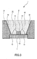
- a white light source will be explained hereinafter with reference to the schematic cross-sectional view of FIG.3 .
- a white light source 1 includes a blue light-emitting diode 21 on a pad 12 formed on a device substrate 11.
- the device substrate 11 is provided with insulated electrodes 13 and 14 to supply electrical power for activating the blue light-emitting diode 21, and the respective electrodes 13 and 14 are connected to the blue light-emitting diode 21 through lead wires 15 and 16, for example.
- a resin layer 31 is provided around the blue light-emitting diode 21 and the resin layer 31 has an opening 32 that opens above the blue light-emitting diode 21.
- This opening 32 is formed by an inclined plane having a wider opening area in the emission direction of the blue light-emitting diode 21 and a reflective film 33 is formed on the inclined plane.
- the wall of the opening 32 is covered with the reflective film 33 and the blue light-emitting diode 21 is disposed at the bottom of the opening 32.
- the white light source 1 is constituted by filling a kneaded material 43 formed by kneading a transparent resin with a red phosphor and a green phosphor into the opening 32 such that the kneaded material 43 covers the blue light-emitting diode 21.
- a red phosphor represented by the above described composition formula (1) is used as this red phosphor.
- This red phosphor has a peak emission wavelength in a red wavelength range (for example, a wavelength between 620 nm and 770 nm), a high light-emitting intensity and a high brightness. For this reason, a bright white light with a high color gamut can be obtained by three primary colors of light comprised of blue light of the blue LED, green light of the green phosphor and red light of the red phosphor.
- an illumination apparatus 5 comprises an illumination substrate 51 on which a plurality of white light sources 1 explained by using FIG. 3 are arranged.
- Exemplary arrangement of the white light sources may be a square lattice arrangement as shown in FIG.4A or may be an arrangement wherein adjacent rows are shifted by 1/2 pitch as shown in FIG.4B .
- the shifting amount is not limited to 1/2 pitch but may be 1/3 pitch or 1/4 pitch.
- every row or every few rows may be shifted.
- every column may be shifted by 1/2 pitch.
- the shifting amount is not limited to 1/2 pitch but may be 1/3 pitch or 1/4 pitch.
- every column or every few columns may be shifted.
- the way of shifting of the white light sources 1 has no limitation.
- the white light source 1 has a constitution same as the constitution explained by using FIG. 3 . That is, the white light source 1 includes a kneaded material 43 formed by kneading a transparent resin with a red phosphor and a green phosphor on the blue light-emitting diode 21. A red phosphor represented by the above described composition formula (1) is used as this red phosphor.
- the illumination apparatus 5 can be used as a back light for a liquid crystal display device since plurality of the white light sources 1 substantially equivalent to point-light emitting devices are two-dimensionally arranged on the illumination substrate 51, which is substantially equivalent to surface emission device. Furthermore, the illumination apparatus 5 can be used for various applications including an ordinary illumination apparatus, an illumination apparatus for photographing and an illumination apparatus for construction site.
- the illumination apparatus 5 provides a bright white light with a high color gamut by using the white light source 1. For example, in the case of using it as a back light of liquid crystal display device, a pure white color with a high brightness can be expressed on the display screen, thereby improving display quality.
- a liquid crystal display device will be explained hereinafter with reference to the schematic configuration view of FIG.5 .
- a liquid crystal display device 100 shown in FIG. 5 includes a liquid crystal display panel 110 having a transparent display unit and a back light 120 provided at a back side (a side opposite to a display surface) of the liquid crystal display panel 110.
- the illumination apparatus 5 explained by using FIG. 4 is used as this back light 120.
- the liquid crystal display device 100 can illuminate the liquid crystal display panel 110 with a bright white light with high color gamut by three primary colors of light by using the illumination apparatus 5. Consequently, a pure white color with a high brightness can be expressed on the display screen of the liquid crystal display panel 110, thereby improving display quality.
- Light-emitting properties were evaluated with respect to plurality of red phosphors respectively using europium oxide (Eu 2 O 3 ), europium acetate (Eu(CH 3 COO) 3 ⁇ nH 2 O), europium carbonate (Eu 2 (CO 3 ) 3 ) and europium nitride (EuN) as a source of europium that is an augmenting agent.
- europium oxide Eu 2 O 3
- Eu(CH 3 COO) 3 ⁇ nH 2 O europium carbonate
- Eu 2 (CO 3 ) 3 europium carbonate
- EuN europium nitride
- FIG.6 is a flowchart showing an exemplary method for manufacturing a red phosphor.
- europium oxide (Eu 2 O 3 ) was used as a source of europium.
- melamine which was used as a flux, was added at a predetermined ratio with respect to the total mole number of europium oxide, strontium carbonate, silicon nitride and aluminum nitride.
- Raw material mixing step S21 was performed by employing liquid-phase method (wet process), using ethanol as a solvent, stirring the respective starting compounds for 30 minutes, and filtering them under reduced pressure to separate precipitate.
- the precipitate was dried for eight hours at a temperature of 80 ° C and then filtered by using #110 mesh to obtain a precursor mixture.
- Primary firing step S22 was performed by weighing the precursor mixture to a predetermined amount, filling the weighed precursor mixture into a melting pot made of boron nitride (BN) and firing the precursor mixture for two hours at a H 2 gas concentration of 4% and a heat process temperature of 1400° C.
- BN boron nitride
- First milling step S23 was performed by milling the fired product produced in the primary firing step by using an agate mortar and then filtering it with a #100 mesh (having an aperture size of 200 ⁇ m) to obtain first powder.
- Secondary firing step S24 was performed by firing the first powder within a melting pot made of boron nitride (BN) for two hours at an ordinary pressure, a H 2 gas concentration of 4% and a heat process temperature of 1750° C.
- BN boron nitride
- Second milling step S25 was performed by milling the secondary fired product by using an agate mortar and then filtering it with a #420 mesh (having an aperture size of 26 ⁇ m).
- Red phosphors represented by composition formula (2) were obtained by above described two-step ordinary pressure firing. Analysis of respective red phosphors by using an Inductively Coupled Plasma (ICP) optical emission spectrometer revealed that strontium, europium, aluminum and silicon constituting the composition formula (2) contained in the starting compounds were also contained in the red phosphors with a substantially same molar ratio (atomic ratio). In addition, analysis of carbon contents (Z) in the respective red phosphors by using an ICP optical emission spectrometer and combustion in oxygen atmosphere-NDIR detection method (device: EMIA-U511 (HORIBA, Ltd.)) revealed that the carbon contents (Z) were in the range of 0 ⁇ z ⁇ 1. (Sr m-x Eu x )Al y (Si 1-z C z ) 9 O n N [12+y-2(n-m)/3] composition formula (2)
- europium acetate Eu(CH 3 COO) 3 ⁇ nH 2 O
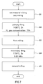
- FIG. 7 is a flowchart showing an exemplary method for manufacturing a red phosphor.
- europium carbonate (Eu 2 (CO 3 ) 3 ) was used as a europium source.
- melamine which was used as a flux, was added at a predetermined ratio with respect to the total mole number of europium carbonate, strontium carbonate, silicon nitride and aluminum nitride.
- Raw material mixing step S31 was performed by employing liquid-phase method (wet process), using ethanol as a solvent, stirring the respective starting compounds for 30 minutes, and filtering them under reduced pressure to separate precipitate.
- the precipitate was dried for eight hours at a temperature of 80 ° C and then filtered by using #110 mesh to obtain a precursor mixture.
- Primary firing step S32 was performed by weighing the precursor mixture to a predetermined amount, filling the weighed precursor mixture into a melting pot made of boron nitride (BN) and firing the precursor mixture for two hours at a H 2 gas concentration of 75% and a heat process temperature of 1400° C.
- BN boron nitride
- First milling step S33 was performed by milling the fired product produced in the primary firing step by using an agate mortar and then filtering it with a #100 mesh (having an aperture size of 200 ⁇ m) to obtain first powder.
- Secondary firing step S34 was performed by firing the first powder within a melting pot made of boron nitride (BN) for two hours under a pressurized nitrogen (N2) atmosphere of 0.85 MPa and a heat process temperature of 1750° C.
- BN boron nitride
- N2 pressurized nitrogen
- Second milling step S35 was performed by milling the secondary fired product by using an agate mortar and then filtering it with a #420 mesh (having an aperture size of 26 ⁇ m).
- Analysis of the respective red phosphors obtained by the two-step pressurized firing by using ICP optical emission spectrometer revealed that strontium, europium, aluminum and silicon constituting the composition formula (2) contained in the starting compounds were also contained in the red phosphors with a substantially same molar ratio (atomic ratio).
- analysis of carbon contents (Z) in the respective red phosphors by using an ICP optical emission spectrometer and combustion in oxygen atmosphere-NDIR detection method revealed that the carbon contents (Z) were in the range of 0 ⁇ z ⁇ 1.
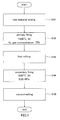
- the raw material mixing step S101 was performed by adding melamine, which was used as a flux, at a predetermined ratio with respect to the total mole number of europium nitride, strontium carbonate, silicon nitride and aluminum nitride and milling and mixing the starting compounds within an agate mortar within a glove box filled with nitrogen atmosphere to form a mixture.
- Primary firing step S102 was performed by weighing the mixture to a predetermined amount, filling the weighed mixture into a melting pot made of boron nitride (BN) and firing the mixture for two hours at a H 2 gas concentration of 75% and a heat process temperature of 1400° C.
- BN boron nitride
- First milling step S103 was performed by milling the fired product fired by the primary firing by using an agate mortar within a glove box filled with nitrogen atmosphere and then filtering it with a #100 mesh (having an aperture size of 200 ⁇ m) to obtain first powder.
- Secondary firing step S104 was performed by firing the first powder within a melting pot made of boron nitride (BN) for two hours under a pressurized nitrogen (N2) atmosphere of 0. 85 MPa and a heat process temperature of 1750° C.
- BN boron nitride
- N2 pressurized nitrogen
- Second milling step S105 was performed by milling the secondary fired product by using an agate mortar within a glove box filled with nitrogen atmosphere and then filtering it with a #420 mesh (having an aperture size of 26 ⁇ m).
- Analysis of the respective red phosphors obtained by the conventional manufacturing method by using ICP optical emission spectrometer revealed that strontium, europium, aluminum and silicon constituting the composition formula (2) contained in the starting compounds were also contained in the red phosphors with a substantially same molar ratio (atomic ratio).
- analysis of carbon contents (Z) in the respective red phosphors by using an ICP optical emission spectrometer and combustion in oxygen atmosphere-NDIR detection method revealed that the carbon contents (Z) were in the range of 0 ⁇ z ⁇ 1.
- FIGs. 8 and 9 are graphs respectively showing peak intensity ratios (YAG standard) and internal quantum efficiencies of respective red phosphors produced by using europium oxide (Eu 2 O 3 ), europium acetate (Eu(CH 3 COO) 3 ⁇ nH 2 O), europium carbonate (Eu 2 (CO 3 ) 3 ) and europium nitride (EuN) as a source of europium.
- the peak intensity ratios were measured by using a fluorescence spectrophotometer FP-6500 produced by JASCO Corporation, filling phosphor powder into dedicated cell and illuminating blue excitation light with a wavelength of 450 nm.
- the internal quantum efficiencies were measured also by using the fluorescence spectrophotometer FP-6500 produced by JASCO Corporation.
- the internal quantum efficiencies of red phosphors were calculated from the resulting fluorescence spectra by using a quantum efficiency measuring software appended to the fluorescence spectrophotometer.
- europium acetate and europium carbonate are stable in the air, they eliminate the necessity of storage in an ordinary desiccator as well as weighing and mixing in a glove box, thereby improving operational efficiency.
- FIGs. 10 and 11 are graphs respectively showing peak intensity ratios (YAG standard) and internal quantum efficiencies of respective red phosphors produced by wet mixing or dry mixing.
- FIGs. 12 and 13 are graphs respectively showing peak intensity ratios (YAG standard) and internal quantum efficiencies of respective red phosphors produced by pressurized firing and ordinary pressure firing.
- FIG. 14 is a graph showing peak intensity ratios (YAG standard) of respective red phosphors produced by using H 2 gas concentration of 4%, 50% and 75% during primary firings.
- the H 2 gas concentration during primary firing could be 0 to 4% and a red phosphor obtained by using H 2 gas concentration of 0% during primary firing had a peak intensity ratio (YAG standard) equal to or larger than that of a red phosphor obtained by using H 2 gas concentration of 75%.
- FIG. 15 is a flowchart of this one-step ordinary pressure firing.
- europium oxide (Eu 2 O 3 ) was used as a source of europium.
- melamine which was used as a flux, was added at a predetermined ratio with respect to the total mole number of europium oxide, strontium carbonate, silicon nitride and aluminum nitride.
- Raw material mixing step S41 was performed by employing liquid-phase method (wet process), using ethanol as a solvent, stirring the respective starting compounds for 30 minutes, and filtering them under reduced pressure to separate precipitate.
- the precipitate was dried for eight hours at a temperature of 80 ° C and then filtered by using #110 mesh to obtain a precursor mixture.
- Firing step S42 was performed by weighing the precursor mixture to a predetermined amount, filling the weighed precursor mixture into a melting pot made of boron nitride (BN) and firing the precursor mixture for two hours at a H 2 gas concentration of 4% and a heat process temperature of 1750° C.
- BN boron nitride
- Milling step S43 was performed by milling the fired product by using an agate mortar and then filtering it with a #420 mesh (having an aperture size of 26 ⁇ m).
- Analysis of the respective red phosphors obtained by this one-step ordinary pressure firing by using ICP optical emission spectrometer revealed that strontium, europium, aluminum and silicon constituting the composition formula (2) contained in the starting compounds were also contained in the red phosphors with a substantially same molar ratio (atomic ratio).
- analysis of carbon contents (Z) in the respective red phosphors by using an ICP optical emission spectrometer and combustion in oxygen atmosphere-NDIR detection method revealed that the carbon contents (Z) were in the range of 0 ⁇ z ⁇ 1.
- This example reveals that the primary firing (1400° C, 2h) of the two-step ordinary pressure firing can be omitted, thereby reducing process time. It was further revealed that a uniform composition can be obtained from one-step ordinary pressure firing by using #110 mesh pass, for example, after the mixing of precursor.
- FIGs. 16 and 17 are graphs respectively showing peak intensity ratios (YAG standard) and internal quantum efficiencies of respective red phosphors produced by two-step pressurized firing, two-step ordinary pressure firing and one-step ordinary pressure firing.
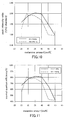
- FIG. 18 is a graph showing peak intensity ratios (YAG standard) of respective red phosphors produced by firing at 1500° C, 1600° C, 1700° C, 1750° C and 1800° C. It was revealed that changing the firing temperature of the secondary firing step would change the optimal value of melamine amount. It was further revealed that the peak intensity ratio (YAG standard) increased along with increase in the firing temperature.
- FIG. 19 is a graph showing maximum peak intensity ratios (YAG standard) of respective red phosphors produced by firing at 1500° C, 1600° C, 1700° C, 1750° C and 1800° C. Among these, secondary firing temperature of 1750 ° C achieved the largest maximum peak intensity ratio under the above described two-step ordinary pressure condition.
- a red phosphor with another composition was produced by the steps shown in the flowchart of FIG. 20 .
- europium oxide (Eu 2 O 3 ) was used as a source of europium.
- melamine which was used as a flux, was added at a predetermined ratio with respect to the total mole number of europium oxide, strontium carbonate, calcium carbonate, silicon nitride and aluminum nitride.
- Raw material mixing step S51 was performed by employing a liquid-phase method (wet process), using ethanol as a solvent, stirring the respective starting compounds for 30 minutes, and filtering them under reduced pressure to separate precipitate.
- the precipitate was dried for eight hours at a temperature of 80 ° C and then filtered by using #110 mesh to obtain a precursor mixture.
- Primary firing step S52 was performed by weighing the mixture to a predetermined amount, filling the weighed mixture into a melting pot made of boron nitride (BN) and firing the mixture for two hours at a nitrogen gas concentration of 100% (H 2 gas concentration of 0%) and a heat process temperature of 1400° C.
- BN boron nitride
- First milling step S53 was performed by milling the fired product fired by the primary firing by using an agate mortar and then filtering it with a #100 mesh (having an aperture size of 200 ⁇ m) to obtain first powder.
- Secondary firing step S54 was performed by firing the first powder within a melting pot made of boron nitride (BN) for two hours at an ordinary pressure, a nitrogen gas concentration of 100% (H 2 gas concentration of 0%) and a heat process temperature of 1700° C.
- BN boron nitride
- Second milling step S55 was performed by milling the secondary fired product by using an agate mortar and then filtering it with a #420 mesh (having an aperture size of 26 ⁇ m).
- Red phosphors represented by composition formula (3) were obtained by above described two-step ordinary pressure firing in nitrogen atmosphere. Analysis of respective red phosphors by using an Inductively Coupled Plasma (ICP) optical emission spectrometer revealed that strontium, calcium, europium, aluminum and silicon constituting the composition formula (3) contained in the starting compounds were also contained in the red phosphors with a substantially same molar ratio (atomic ratio). In addition, analysis of carbon contents (Z) in the respective red phosphors by using an ICP optical emission spectrometer and combustion in oxygen atmosphere-NDIR detection method (device: EMIA-U511 (HORIBA, Ltd.)) revealed that the carbon contents (Z) were in the range of 0 ⁇ z ⁇ 1. [(Sr 0.7 ,Ca 0.3 ) m-x Eu x ]Al y (Si 1-z C z ) 9 O n N [12+y-2(n-m)/3] composition formula (3)
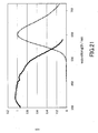
- FIG. 21 shows emission/excitation spectrum of a red phosphor (melamine amount of 26 mol%) represented by the composition formula (3).
- the spectrum shown in FIG. 21 reveals that this red phosphor absorbs blue light and emits red light having an emission peak around 650 nm, which is suitable as a phosphor for white LED with blue LED excitation.
- FIGs.22 and 23 are graphs respectively showing peak intensity ratios (YAG standard) and internal quantum efficiencies of respective red phosphors against melamine amounts.
- the inventors of the present invention found that an excellent emission intensity can be achieved when X-ray diffraction (XRD) spectrum of the above described red phosphor containing europium (Eu), silicon (Si), aluminum(Al), carbon (C), oxygen (0) and nitrogen (N) shows a specific diffraction pattern.
- XRD X-ray diffraction
- composition formula (4) wherein z and n satisfy the relation: 0 ⁇ z ⁇ 1 and 0 ⁇ n ⁇ 10.
- Emission spectra and X-ray diffraction spectra of these samples 1 to 4 with different melamine addition amounts were measured.
- the emission spectra were measured by using a fluorescence spectrophotometer FP-6500 produced by JASCO Corporation.
- the emission spectra were measured by filling phosphor powder into dedicated cell and illuminating blue excitation light with a wavelength of 450 nm. Subsequently, emission peak intensities were calculated based on the maximum peak heights of the emission spectra.
- the X-ray diffraction spectra were measured by using powder X-ray diffraction analyzer for X-ray of Cu-K ⁇ (Rigaku Corporation).
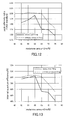
- FIG.24 shows emission spectra of respective red phosphors (sample 1) with different melamine addition amounts. As shown in FIG. 24 , it was revealed that emission intensity increased and light-emission shifted toward shorter wavelength side as the melamine addition amount increased.
- FIG. 25 shows XRD spectra of respective red phosphors (sample 1) with different melamine addition amounts normalized by the peak intensity existing at a position corresponding to a diffraction angle of 35° to 36°.
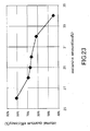
- FIG.26 is a graph showing diffraction peak intensity ratios of peak intensities of respective diffraction angles to the peak intensity existing at a position corresponding to a diffraction angle of 35.0° to 36.0°.
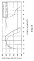
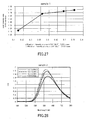
- FIG.27 shows a relation between a diffraction peak intensity ratio of the peak intensity existing at a position corresponding to a diffraction angle of 36.0° to 36.6° to the peak intensity existing at a position corresponding to a diffraction angle of 35.0° to 36.0° and an emission peak intensity ratio (YAG standard).
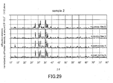
- FIG.28 shows emission spectra of respective red phosphors (sample 2) with different melamine addition amounts. As shown in FIG. 28 , it was revealed that emission intensity increased and light-emission shifted toward shorter wavelength side as the melamine addition amount increased.
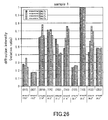
- FIG. 29 shows XRD spectra of respective red phosphors (sample 2) with different melamine addition amounts normalized by the peak intensity existing at a position corresponding to a diffraction angle of 35° to 36° .
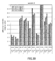
- FIG.30 is a graph showing diffraction peak intensity ratios of peak intensities of respective diffraction angles to the peak intensity existing at a position corresponding to a diffraction angle of 35. 0° to 36. 0° .
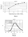
- FIG. 31 shows a relation between a diffraction peak intensity ratio of the peak intensity existing at a position corresponding to a diffraction angle of 36. 0° to 36. 6° to the peak intensity existing at a position corresponding to a diffraction angle of 35. 0° to 36. 0° and an emission peak intensity ratio (YAG standard).
- FIG.32 shows emission spectra of respective red phosphors (sample 3) with different melamine addition amounts. As shown in FIG. 32 , it was revealed that emission intensity increased and light-emission shifted toward shorter wavelength side as the melamine addition amount increased.
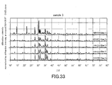
- FIG. 33 shows XRD spectra of respective red phosphors (sample 3) with different melamine addition amounts normalized by the peak intensity existing at a position corresponding to a diffraction angle of 35° to 36° .
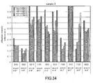
- FIG.34 is a graph showing diffraction peak intensity ratios of peak intensities of respective diffraction angles to the peak intensity existing at a position corresponding to a diffraction angle of 35.0° to 36.0°.
- FIG. 35 shows a relation between a diffraction peak intensity ratio of the peak intensity existing at a position corresponding to a diffraction angle of 36.0° to 36.6° to the peak intensity existing at a position corresponding to a diffraction angle of 35. 0° to 36. 0° and emission peak intensity ratio (YAG standard).
- FIG.36 shows emission spectra of respective red phosphors (sample 4) with different melamine addition amounts. As shown in FIG. 36 , it was revealed that emission intensity increased and light-emission shifted toward shorter wavelength side as the melamine addition amount increased.
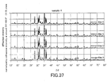
- FIG. 37 shows XRD spectra of respective red phosphors (sample 4) with different melamine addition amounts normalized by the peak intensity existing at a position corresponding to a diffraction angle of 35° to 36° .
- FIG.38 is a graph showing diffraction peak intensity ratios of peak intensities of respective diffraction angles to the peak intensity existing at a position corresponding to a diffraction angle of 35. 0° to 36.0° .
- FIG.39 shows a relation between a diffraction peak intensity ratio of the peak intensity existing at a position corresponding to a diffraction angle of 36.0° to 36.6° to the peak intensity existing at a position corresponding to a diffraction angle of 35.0° to 36.0° and an emission peak intensity ratio (YAG standard).
- a red phosphor with a crystal structure having an intensity ratio of the diffraction peak caused by (112) plane to the diffraction peak caused by (113) plane equal to or more than 0.65 could achieve an emission peak intensity ratio (YAG standard) equal to or more than 1.5.
- red phosphors manufactured by the present method were compared to red phosphors having the same composition manufactured by a conventional method.
- a red phosphor of reference example 1 was manufactured by two-step ordinary pressure firings using wet mixing as shown in the flowchart of FIG. 6 by using europium oxide (Eu 2 O 3 ) as a source of europium. Charge amount of melamine was 29 mol%.
- a red phosphor of reference example 2 was manufactured by one-step ordinary pressure firing using wet mixing as shown in the flowchart of FIG. 15 by using europium oxide (Eu 2 O 3 ) as a source of europium. Charge amount of melamine was 29 mol%.
- a conventional red phosphor was manufactured by the conventional method shown in FIG. 1 by using europium nitride (EuN) as a source of europium. That is, raw material mixing step S101 was performed by using dry mixing, primary firing step S102 was performed under H 2 gas concentration of 75%, and secondary firing step S104 was performed under a pressurized condition of 0.85 MPa. Charge amount of melamine was 30 mol%, and charge amounts of the other raw materials, Sr, Eu, Al and Si, were selected to be the same composition of the red phosphor of the present method.
- EuN europium nitride
- carbon content of the red phosphor of reference example 1 was 0.032 wt%, or 0.023 when scaled to the value of z in composition formula (2)
- carbon content of the red phosphor of reference example 2 was 0. 1 wt%, or 0. 072 when scaled to the value of z in composition formula (2).
- carbon content of the red phosphor manufactured by the conventional method was 0.038 wt%, or 0.027 when scaled to the value of z in composition formula (2).
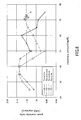
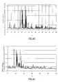
- FIG. 40 shows XRD spectra of the red phosphor of reference example 1 normalized by the peak intensity existing at a position corresponding to a diffraction angle of 35° to 36° .
- the red phosphor of reference example 1 had an intensity ratio of the diffraction peak caused by (112) plane to the diffraction peak caused by (113) plane of 0.93.
- the emission peak intensity ratio (YAG standard) of the red phosphor of reference example 1 was 1.99.
- the red phosphor of reference example 2 had an intensity ratio of the diffraction peak caused by (112) plane to the diffraction peak caused by (113) plane of 1. 00.
- the emission peak intensity ratio (YAG standard) of the red phosphor of reference example 2 was 1.74.
- FIG. 41 shows XRD spectra of the red phosphor manufactured by the conventional method normalized by the peak intensity existing at a position corresponding to a diffraction angle of 35° to 36° .
- the red phosphor manufactured by conventional method had an intensity ratio of the diffraction peak caused by (112) plane to the diffraction peak caused by (113) plane of 0.23.
- the emission peak intensity ratio (YAG standard) of the red phosphor manufactured by conventional method was 0.82.
- conventional method cannot produce a crystal structure having an intensity ratio of the diffraction peak caused by (112) plane to the diffraction peak caused by (113) plane equal to or more than 0.65 in orthorhombic space group Pmn21 when the carbon content (z) is 0.072 or less.
- the crystal structure of the red phosphor produced by the present method differs from that of the red phosphor produced by the conventional method in that the intensity ratio of the diffraction peak caused by (112) plane to the diffraction peak caused by (113) plane is equal to or more than 0. 65 in orthorhombic space group Pmn21 even if the carbon content (z) is 0.072 or less.
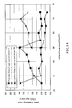
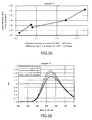
- FIG.42 is a graph showing, with regard to respective red phosphors with different melamine addition amounts, relations between emission intensities at an excitation wavelength of 550 nm relative to the value of an emission intensity at an excitation wavelength of 400 nm supposed to be 1 (denoted as 550 nm PLE intensity/440 nm PLE intensity hereinafter) and external quantum efficiencies.
- the 550 nm PLE intensity/440 nm PLE intensity is a relative value of the emission intensity at the excitation wavelength of 550 nm to the value of the emission intensity at the excitation wavelength of 400 nm supposed to be 1 in PLE spectra of respective red phosphors.
- the external quantum efficiencies of the respective red phosphors were measured by using the fluorescence spectrophotometer FP-6500 produced by JASCO Corporation.
- fluorescence spectra were measured by filling phosphor powder into dedicated cell and illuminating blue excitation light with a wavelength of 450 nm, and then the external quantum efficiencies of red phosphors were calculated from the resulting fluorescence spectra by using a quantum efficiency measuring software appended to the fluorescence spectrophotometer.
- the red phosphors of reference samples A and B were manufactured by two-step ordinary pressure firings using wet mixing as shown in the flowchart of FIG. 6 by using europium oxide (Eu 2 O 3 ) as a source of europium.
- Eu 2 O 3 europium oxide
- Melamine addition amounts were in a range of 22 to 50 mol% to the total mole number of calcium carbonate, europium oxide, silicon nitride and aluminum nitride.
- the graph shown in FIG.42 reveals that a high external quantum efficiency can be obtained by 550 nm PLE intensity/440 nm PLE intensity of 0.48 or more.
- the red phosphor obtainable by the present invention has an X-ray diffraction pattern in which a peak intensity existing at a position corresponding to a diffraction angle of 36° to 36. 6° is 0. 65 times or more than a peak intensity existing at a position corresponding to a diffraction angle of 35° to 36° , thereby showing an excellent light-emitting property.
- This red phosphor shows an excellent light-emitting property even if the carbon content (Z) in the red phosphor shown in the composition formula (1) is 0.072 or less. In the case that the carbon content (Z) in the red phosphor is low, the amount of melamine for using as raw material can be reduced, thereby suppressing the amount of raw material to be used and improving cost performance.
- the manufacturing method according to an embodiment of the present invention can reduce charge amount of melamine, thereby reducing the cost related to the use of melamine. Moreover, reduction of the charge amount of melamine can prevent adverse effect such as clogging of ducts of a device with melamine, thereby eliminating the necessity of providing a filter at a downstream portion of a device and reducing running cost.
Landscapes
- Chemical & Material Sciences (AREA)
- Engineering & Computer Science (AREA)
- Physics & Mathematics (AREA)
- Inorganic Chemistry (AREA)
- Materials Engineering (AREA)
- Organic Chemistry (AREA)
- Nonlinear Science (AREA)
- Microelectronics & Electronic Packaging (AREA)
- Computer Hardware Design (AREA)
- Power Engineering (AREA)
- Crystallography & Structural Chemistry (AREA)
- Mathematical Physics (AREA)
- General Physics & Mathematics (AREA)
- Optics & Photonics (AREA)
- Manufacturing & Machinery (AREA)
- Spectroscopy & Molecular Physics (AREA)
- General Engineering & Computer Science (AREA)
- Luminescent Compositions (AREA)
- Liquid Crystal (AREA)
- Led Device Packages (AREA)
Description
- This invention relates to a method for manufacturing a red phosphor having an emission peak wavelength in a red wavelength range (for example, a wavelength between 620 nm and 770 nm). This application claims priorities to Japanese Patent Application No.
2011-108870, filed on May 14, 2011 2011-263327, filed on December 1, 2011 - Recently, in the field of application of high color gamut back lights and Light Emitting Diodes (LEDs) having high color rendering properties, there have been increasing demand for red phosphors that emits red light with blue LED excitation. Accordingly, nitride red phosphors having chemical stabilities and high efficiencies have been developed.
- For example,
PLT 1 discloses a manufacturing of a red phosphor containing europium (Eu), silicon (Si), oxygen (0) and nitrogen (N) by using a europium nitride (EuN) as a source of europium (Eu). - PLT 1: Japanese Unexamined Patent Application Publication No.
2011-1530 - However, the technology of
PLT 1, which mixes raw materials by a dry mixing (milling and mixing by using a mortar) to produce a mixture, tends to cause composition nonuniformity in the mixture, making it difficult to improve productivity. - Having regard to the above, an object of the present invention is to provide a method for manufacturing a red phosphor capable of improving productivity.
- Another object of the present invention is to provide a red phosphor with an excellent light-emitting property, as well as a white light source, an illumination apparatus and a liquid crystal display device using this red phosphor.
- To solve the above-described problem, a method for manufacturing a red phosphor according to the present invention comprises steps of: mixing an element A-containing compound, a nitrogen-free europium compound, a silicon-containing compound, an aluminum-containing compound and a carbon-containing reducing agent so as to form a mixture, the atomic ratio among element A, europium (Eu), silicon (Si), aluminum(Al) and carbon (C) being a value represented by composition formula (1) ; firing the mixture; and milling the fired mixture,
(Am-xEux)Aly(Si1-zCz)9OnN[12+y-2(n-m)/3] composition formula (1)
wherein the element A is at least one element selected from the group of magnesium (Mg), calcium (Ca), strontium (Sr) and barium (Ba), and m, x, z and n satisfy the relation: 3 < m < 5, 0 < x < 1, 0 ≦ y < 2, 0 < z < 1, and 0 < n < 10,
wherein the nitrogen-free europium compound is at least one of europium acetate and europium carbonate, and
the mixture is formed by mixing a carbonate compound of the element A, the nitrogen-free europium compound, silicon nitride, aluminum nitride and the carbon-containing reducing agent, wherein the mixture is produced by a wet process, wherein the carbon-containing reducing agent is a melamine, and
the addition amount of the melamine is equal to or less than 65% of the total mole number of the carbonate compound of the element A, nitrogen-free europium compound, silicon nitride and aluminum nitride. - In addition, a red phosphor obtainable by the present invention has an X-ray diffraction pattern in which a peak intensity existing at a position corresponding to a diffraction angle of 36° to 36. 6° is 0. 65 times or more than a peak intensity existing at a position corresponding to a diffraction angle of 35° to 36° .
- The present invention, using a nitrogen-free europium compound as a source of europium, allows a mixing by a wet process, thereby preventing composition nonuniformity in the mixture and improving productivity.
- Furthermore, the present invention provides a crystal structure having a specific X-ray diffraction pattern, thereby achieving an excellent light-emitting property.
-
-
FIG. 1 . is a flowchart showing a conventional method for manufacturing a red phosphor. -
FIG.2 . is a flowchart showing a method for manufacturing a red phosphor according to one embodiment of the present invention. -
FIG. 3 is a schematic cross-sectional view of a white light source. -
FIG. 4A is a schematic plane view of an exemplary illumination apparatus with a square lattice arrangement andFIG. 4B is a schematic plane view of an exemplary illumination apparatus with an arrangement wherein adjacent rows are shifted by 1/2 pitch. -
FIG. 5 is a schematic configuration view of a liquid crystal display device. -
FIG.6 is a flowchart showing an exemplary manufacturing method (two-step ordinary pressure firing) of a red phosphor. -
FIG. 7 is a flowchart showing an exemplary manufacturing method (two-step pressurized firing) of a red phosphor. -
FIG. 8 is a graph showing peak intensity ratios (YAG standard) of respective red phosphors produced by using Eu2O3, Eu(CH3COO)3·nH2O, Eu2(CO3)3 and EuN as a source of europium. -
FIG. 9 is a graph showing internal quantum efficiencies of respective red phosphors produced by using Eu2O3, Eu(CH3COO)3·nH2O, Eu2(CO3)3 and EuN as a source of europium. -
FIG.10 is a graph showing peak intensity ratios (YAG standard) of respective red phosphors produced by wet mixing or dry mixing. -
FIG. 11 is a graph showing internal quantum efficiencies of respective red phosphors produced by wet mixing or dry mixing. -
FIG.12 is a graph showing peak intensity ratios (YAG standard) of respective red phosphors produced by pressurized firing and ordinary pressure firing. -
FIG. 13 is a graph showing internal quantum efficiencies of respective red phosphors produced by pressurized firing and ordinary pressure firing. -
FIG. 14 is a graph showing peak intensity ratios of respective red phosphors produced by using H2 gas concentration of 4%, 50% and 75% during primary firings. -
FIG. 15 is a flowchart showing an exemplary manufacturing method (one-step ordinary pressure firing) of a red phosphor. -
FIG.16 is a graph showing peak intensity ratios (YAG standard) of respective red phosphors produced by two-step pressurized firing, two-step ordinary pressure firing and one-step ordinary pressure firing. -
FIG. 17 is a graph showing internal quantum efficiencies of respective red phosphors produced by two-step pressurized firing, two-step ordinary pressure firing and one-step ordinary pressure firing. -
FIG.18 is a graph showing peak intensity ratios (YAG standard) of respective red phosphors produced by firing at 1500° C, 1600° C, 1700° C, 1750° C and 1800° C. -
FIG. 19 is a graph showing maximum peak intensity ratios (YAG standard) of respective red phosphors produced by firing at 1500° C, 1600° C, 1700° C, 1750° C and 1800° C. -
FIG. 20 is a flowchart showing an exemplary manufacturing method (two-step ordinary pressure firing in nitrogen atmosphere) of a red phosphor. -
FIG.21 shows emission/excitation spectrum of a red phosphor. -
FIG.22 is a graph showing peak intensity ratios (YAG standard) of respective red phosphors against melamine amounts. -
FIG. 23 is a graph showing internal quantum efficiencies of respective red phosphors against melamine amounts. -
FIG. 24 shows emission spectra of respective red phosphors (sample 1) with different melamine addition amounts. -
FIG. 25 shows XRD spectra of respective red phosphors (sample 1) with different melamine addition amounts normalized by the peak intensity existing at a position corresponding to a diffraction angle of 35° to 36° . -
FIG.26 is a graph showing diffraction peak intensity ratios of peak intensities of respective diffraction angles to the peak intensity existing at a position corresponding to a diffraction angle of 35. 0° to 36. 0° in XRD spectra of respective red phosphors (sample 1) with different melamine addition amounts. -
FIG.27 shows a relation between a diffraction peak intensity ratio of the peak intensity existing at a position corresponding to a diffraction angle of 36. 0° to 36. 6° to the peak intensity existing at a position corresponding to a diffraction angle of 35. 0° to 36.0° and an emission peak intensity ratio (YAG standard) in XRD spectra of respective red phosphors (sample 1) with different melamine addition amounts. -
FIG. 28 shows emission spectra of respective red phosphors (sample 2) with different melamine addition amounts. -
FIG.29 shows XRD spectra of respective red phosphors (sample 2) with different melamine addition amounts normalized by the peak intensity existing at a position corresponding to a diffraction angle of 35° to 36° . -
FIG.30 is a graph showing diffraction peak intensity ratios of peak intensities of respective diffraction angles to the peak intensity existing at a position corresponding to a diffraction angle of 35. 0° to 36. 0° in XRD spectra of respective red phosphors (sample 2) with different melamine addition amounts. -
FIG.31 shows a relation between a diffraction peak intensity ratio of the peak intensity existing at a position corresponding to a diffraction angle of 36.0° to 36. 6° to the peak intensity existing at a position corresponding to a diffraction angle of 35. 0° to 36.0° and an emission peak intensity ratio (YAG standard) in XRD spectra of respective red phosphors (sample 2) with different melamine addition amounts. -
FIG. 32 shows emission spectra of respective red phosphors (sample 3) with different melamine addition amounts. -
FIG.33 shows XRD spectra of respective red phosphors (sample 3) with different melamine addition amounts normalized by the peak intensity existing at a position corresponding to a diffraction angle of 35° to 36° . -
FIG. 34 is a graph showing diffraction peak intensity ratios of peak intensities of respective diffraction angles to the peak intensity existing at a position corresponding to a diffraction angle of 35. 0° to 36. 0° in XRD spectra of respective red phosphors (sample 3) with different melamine addition amounts. -
FIG.35 shows a relation between a diffraction peak intensity ratio of the peak intensity existing at a position corresponding to a diffraction angle of 36. 0° to 36. 6° to the peak intensity existing at a position corresponding to a diffraction angle of 35. 0° to 36. 0° and an emission peak intensity ratio (YAG standard) in XRD spectra of respective red phosphors (sample 3) with different melamine addition amounts. -
FIG. 36 shows emission spectra of respective red phosphors (sample 4) with different melamine addition amounts. -
FIG.37 shows XRD spectra of respective red phosphors (sample 4) with different melamine addition amounts normalized by the peak intensity existing at a position corresponding to a diffraction angle of 35° to 36° . -
FIG. 38 is a graph showing diffraction peak intensity ratios of peak intensities of respective diffraction angles to the peak intensity existing at a position corresponding to a diffraction angle of 35. 0° to 36. 0° in XRD spectra of respective red phosphors (sample 4) with different melamine addition amounts. -
FIG. 39 shows a relation between a diffraction peak intensity ratio of the peak intensity existing at a position corresponding to a diffraction angle of 36. 0° to 36. 6° to the peak intensity existing at a position corresponding to a diffraction angle of 35. 0° to 36. 0° and an emission peak intensity ratio (YAG standard) in XRD spectra of respective red phosphors (sample 4) with different melamine addition amounts. -
FIG. 40 shows XRD spectra of the red phosphor of reference example 1 normalized by the peak intensity existing at a position corresponding to a diffraction angle of 35° to 36° . -
FIG. 41 shows XRD spectra of the red phosphor manufactured by the conventional method normalized by the peak intensity existing at a position corresponding to a diffraction angle of 35° to 36° . -
FIG. 42 is a graph, with regard to red phosphors, showing relations between emission intensities at an excitation wavelength of 550 nm relative to the value of an emission intensity at an excitation wavelength of 400 nm supposed to be 1 and external quantum efficiencies. - Embodiments of the present invention will now be described with reference to the accompanying drawings according to the following order.
- 1. Constitution of red phosphor
- 2. Conventional method for manufacturing red phosphor
- 3. Method for manufacturing red phosphor according to one embodiment of the present invention
- 4. Constitution of red phosphor with excellent light-emitting property
- 5. Exemplary constitution of white light source
- 6. Exemplary constitution of illumination apparatus
- 7. Exemplary constitution of liquid crystal display device
- 8. Examples
- A red phosphor obtainable by the present invention contains element A, europium (Eu), silicon (Si), aluminum (Al) and carbon (C) with an atomic ratio represented by the following composition formula (1):
(Am-xEux)Aly(Si1-zCz)9OnN[12+y-2(n-m)/3] composition formula (1)
wherein the element A is at least one element selected from the group of magnesium (Mg), calcium (Ca), strontium (Sr) and barium (Ba), and m, x, z and n satisfy the relation: 3 < m < 5, 0 ≦ y < 2, 0 < x < 1, 0 < z < 1, and 0 < n < 10. - This composition formula (1) is shown with constant atomic ratio of silicon and carbon being 9. In addition, atomic ratio [12 + y - 2(n-m) / 3] of nitrogen (N) in this composition formula (1) is calculated such that sum of atomic ratios of respective elements in the composition formula (1) will be neutral. In other words, assuming that the atomic ratio of nitrogen (N) in composition formula (1) is δ and that charges of the respective elements constituting composition formula (1) are compensated, the following formula will hold: 2m + 3y + 4 x 9 - 2n - 3 δ = 0. From this formula, the atomic ratio of nitrogen (N) δ is calculated as follows: δ = 12 + y - 2(n-m) / 3.
- Furthermore, the red phosphor represented by this composition formula (1) has a crystal structure belonging to orthorhombic space group Pmn21 and contains carbon (C) as a constituent element. The carbon has a function to remove excessive oxygen (0) during generation process and adjust oxygen amount.
- The red phosphor having this constitution is a chemically stable and highly efficient phosphor that absorbs light in a blue wavelength range and has an emission peak wavelength in a red wavelength range (for example, a wavelength between 620 nm and 770 nm), so that this phosphor is suitable for use in applications such as high color gamut back lights and Light Emitting Diodes (LEDs) having high color rendering properties.
- A conventional method for manufacturing a red phosphor will be explained hereinafter with reference to the flowchart of
FIG. 1 . - Firstly, as shown in
FIG. 1 , raw material mixing step S101 is performed. The starting compounds respectively containing the elements constituting composition formula (1) are mixed by a dry mixing within a glove box filled with nitrogen atmosphere. More particularly, in this dry mixing, the starting compounds are milled and mixed within an agate mortar to form a mixture. - As for the starting compounds containing the elements constituting composition formula (1), a carbonate compound of the element A (for example, strontium carbonate (SrCO3), calcium carbonate (CaCO3) and the like), europium nitride (EuN), silicon nitride (Si3N4), aluminum nitride (AlN) and melamine (C3H6N6) are prepared. The respective starting compounds are weighed to a predetermined molar ratio so that the elements constituting composition formula (1) contained in the prepared starting compounds satisfy the atomic ratio of formula (1). Melamine, which is used as a flux, is added at a predetermined ratio with respect to the total mole number of strontium carbonate, europium nitride, silicon nitride and aluminum nitride. The weighed respective starting compounds are then mixed by dry mixing to form a mixture.
- Next, primary firing step S102 is performed. In this primary firing step, the above described mixture is fired to form a first fired product that is a precursor of a red phosphor. In particular, the mixture is heat-processed for 2 hours within a melting pot made of boron nitride (BN) at a H2 gas concentration of 75% and a heat process temperature of 1400° C.
- This primary firing step thermally decomposes melamine having a melting point less than 250 ° C. The thermally decomposed carbon (C) and hydrogen (H) are combined with a part of oxygen (0) contained in strontium carbonate into carbonic acid gas (CO or CO2) or H2O. Since the carbonic acid gas or H2O is vaporized, a part of oxygen is removed from the strontium carbonate in the first fired product. In addition, nitrogen (N) contained in the decomposed melamine promotes reduction and nitridization.
- Next, first milling step S103 is performed. In this first milling step, the first fired product is milled to form a first powder. In particular, the first fired product is milled by using an agate mortar within a glove box filled with nitrogen atmosphere, and then filtered with a #100 mesh (having an aperture size of 200 µm) to obtain the first powder.
- Next, secondary firing step S104 is performed. In this secondary firing step, the first powder is heat-processed to form a second fired product. In particular, the first powder is heat-processed for 2 hours within a melting pot made of boron nitride (BN) in nitrogen (N2) atmosphere at an increased pressure of 0.85 MPa and a heat process temperature of 1800° C.
- Next, second milling step S105 is performed. In this second milling step, the second fired product is milled to form a second powder. In particular, the second fired product is milled by using an agate mortar within a glove box filled with nitrogen atmosphere, and then filtered with a #420 mesh (having an aperture size of 26 µm).
- The above described process produces a red phosphor represented by composition formula (1) containing respective elements with an atomic ratio mixed in raw material mixing step S101.
- However, in this kind of conventional manufacturing method, raw material mixing step S101 performed by dry mixing (milling and mixing by using a mortar) tends to cause composition nonuniformity in the mixture so that a uniform red phosphor might not be obtained.
- Furthermore, secondary firing step S104, increasing pressure under a high temperature, narrows soaking zone in the heating furnace (around φ 100), thereby limiting firing efficiency. In addition, specialized and high-cost facilities are necessary since the primary firing step S101 requires installation of a safety device due to the heat-process under a strong reducing atmosphere in which hydrogen concentration exceeds the explosion limit of 4% and the secondary firing step S104 requires a heating furnace having a tolerance against high temperature and high pressure due to the pressurizing-process under a high temperature.
- Consequently, conventional manufacturing method, causing composition nonuniformity in the mixture, limiting firing efficiency, and requiring a strong reducing atmosphere and a condition of high temperature and high pressure, hardly improves productivity.
- A method for manufacturing red phosphor according to one embodiment of the present invention will be explained hereinafter with reference to the flowchart of
FIG. 2 . This method for manufacturing red phosphor according to one embodiment of the present invention uses a nitrogen-free europium compound such as europium acetate (Eu(CH3COO)3·nH2O) and europium carbonate (Eu2(CO3)3) as a source of europium that is an augmenting agent. This allows a mixing by a wet process, thereby preventing composition nonuniformity in the mixture and improving productivity. - Firstly, in a raw material mixing step S11, starting compounds containing the elements constituting composition formula (1) are mixed to produce a mixture. In particular, the mixture is produced by mixing a carbonate compound of the element A (at least one of Mg, Ca, Sr and Ba), a nitrogen-free europium compound, silicon nitride, aluminum nitride and melamine with an atomic ratio among element A, europium (Eu), silicon (Si), aluminum (Al) and carbon (C) being a value represented by composition formula (1).
- The addition amount of the melamine is equal to or less than 65% of the total mole number of the carbonate compound of the element A, nitrogen-free europium compound, silicon nitride and aluminum nitride. The melamine amount equal to or less than 65% will realize maximum peak intensity ratio and improve internal quantum efficiency.
- The mixing in this embodiment uses wet process capable of avoiding composition nonuniformity in the mixture. In particular, the wet process is performed by using ethanol as a solvent, stirring the respective starting compounds, filtering them under a reduced pressure to separate precipitate, drying the precipitate, and filtering it by using, for example, #110 mesh. This wet type mixing does not require the use of glove box, thereby improving operational efficiency.
- Next, firing step S12 is performed by filling precursor mixture into a heating furnace and firing it. This firing step S12 is preferably performed under ordinary pressure (atmospheric pressure). This can prevent the soaking zone in the heating furnace from narrowing (around φ 100), thereby avoiding firing efficiency limitation.
- Furthermore, the firing step S12 is preferably performed at a H2 gas concentration equal to or less than 80%, more preferably, equal to or less than 4%. The H2 gas concentration equal to or less than 4% eliminates the necessity of installation of a safety device which might otherwise be required for a heat-process under a strong reducing atmosphere in which hydrogen concentration exceeds the explosion limit of 4%. Furthermore, this embodiment allows a firing in nitrogen atmosphere having a hydrogen concentration of 0%.
- In addition, the firing step S12 is preferably performed at a temperature range of 1400° C to 1800° C. A red phosphor having a high peak intensity can be obtained by the firing at this temperature range.
- Alternatively, the firing step S12 may performed by two steps of primary and secondary firing steps. In this case, composition nonuniformity in the red phosphor can be prevented by performing a first milling step after the primary firing step.
- In the case of using, for example, melamine as carbon-containing reducing agent and strontium carbonate as the element A-containing compound in this firing step S12, the melamine is thermally decomposed and carbon (C) and hydrogen (H) are combined with a part of oxygen (0) contained in the strontium carbonate into carbonic acid gas (CO or CO2) or H2O. Since the carbonic acid gas or H2O is vaporized, a part of oxygen is removed from the strontium carbonate in the fired product. In addition, nitrogen (N) contained in the decomposed melamine promotes reduction and nitridization.
- Next, milling step S13 is performed. In this milling step, the fired product is milled by using an agate mortar within a glove box filled with nitrogen atmosphere, and then filtered with a #420 mesh (having an aperture size of 26 µm).
- The above described process produces a red phosphor represented by composition formula (1) containing respective elements with an atomic ratio mixed in raw material mixing step S11. This red phosphor has an excellent light-emitting property as demonstrated in examples.
- The inventors of the present invention found that an excellent emission intensity can be achieved when X-ray diffraction (XRD) spectrum of the above described red phosphor containing europium (Eu), silicon (Si), aluminum(Al), carbon (C), oxygen (0) and nitrogen (N) shows a specific diffraction pattern.
- In particular, it was found that a high emission intensity can be achieved when the peak intensity existing at a position corresponding to a diffraction angle (2 θ) of 36° to 36. 6° caused by orthorhombic space group Pmn21 (112) plane (denoted as (112) plane hereinafter) has a sufficiently large value with comparison to the peak intensity existing at a position corresponding to a diffraction angle (2 θ) of 35° to 36° caused by orthorhombic space group Pmn21 (113) plane (denoted as (113) plane hereinafter).
- As described above, the red phosphor obtainable by the present invention is manufactured by mixing an element (A), a nitrogen-free europium compound, a silicon-containing compound, an aluminum-containing compound and a carbon-containing reducing agent so as to form a mixture, with the atomic ratio among element (A), europium (Eu), silicon (Si), aluminum(Al) and carbon (C) being a value represented by composition formula (1), firing the mixture, and milling the first fired mixture, and the X-ray diffraction pattern has the peak intensity existing at a position corresponding to a diffraction angle of 36° to 36. 6° that is 0.65 times or more than the peak intensity existing at a position corresponding to a diffraction angle of 35° to 36° .
- The crystal structure having this diffraction peak intensity ratio can achieve an emission peak intensity ratio of 1.5 or more (YAG standard). It should be noted that different diffraction peak intensity ratio means different crystal structure of the red phosphor.
- Moreover, the red phosphor obtainable by the present invention has an X-ray diffraction pattern in which the peak intensity existing at a position corresponding to a diffraction angle of 36° to 36. 6° is 0. 65 times or more than the peak intensity existing at a position corresponding to a diffraction angle of 35° to 36° even if the carbon content (Z) in the red phosphor shown in the composition formula (1) is 0.072 or less, thereby showing an excellent light-emitting property.
- Accordingly, the charge amount of melamine can be reduced in the manufacturing of the red phosphor, thereby preventing adverse effect such as clogging of ducts of a device with melamine.
- Furthermore, the inventors of the present invention found that a high quantum efficiency can be achieved when a photoluminescence excitation (PLE) spectrum shows a predetermined light-emitting property. Particularly, in the photoluminescence excitation (PLE) spectrum of the red phosphor, the relative value of an emission intensity at an excitation wavelength of 550 nm relative to the value of an emission intensity at an excitation wavelength of 400 nm supposed to be 1 (denoted as 550 nm PLE intensity/440 nm PLE intensity hereinafter) is 0.48 or more.
- Furthermore, the red phosphor preferably fulfills the condition of 0. 05 ≦ x ≦ 0. 15 in the composition formula (1). The emission intensity peak of the red phosphor shown in composition formula (1) changes in accordance with the europium (Eu) concentration (x), and the Eu concentration (x) within this range can achieve a high external quantum efficiency.
- A white light source will be explained hereinafter with reference to the schematic cross-sectional view of
FIG.3 . - As shown in
FIG. 3 , awhite light source 1 includes a blue light-emittingdiode 21 on apad 12 formed on adevice substrate 11. Thedevice substrate 11 is provided withinsulated electrodes diode 21, and therespective electrodes diode 21 throughlead wires - In addition, a
resin layer 31 is provided around the blue light-emittingdiode 21 and theresin layer 31 has anopening 32 that opens above the blue light-emittingdiode 21. Thisopening 32 is formed by an inclined plane having a wider opening area in the emission direction of the blue light-emittingdiode 21 and areflective film 33 is formed on the inclined plane. In other words, in theresin layer 31 having the opening 32 formed as mortar-shape, the wall of theopening 32 is covered with thereflective film 33 and the blue light-emittingdiode 21 is disposed at the bottom of theopening 32. Thewhite light source 1 is constituted by filling a kneadedmaterial 43 formed by kneading a transparent resin with a red phosphor and a green phosphor into theopening 32 such that the kneadedmaterial 43 covers the blue light-emittingdiode 21. - A red phosphor represented by the above described composition formula (1) is used as this red phosphor. This red phosphor has a peak emission wavelength in a red wavelength range (for example, a wavelength between 620 nm and 770 nm), a high light-emitting intensity and a high brightness. For this reason, a bright white light with a high color gamut can be obtained by three primary colors of light comprised of blue light of the blue LED, green light of the green phosphor and red light of the red phosphor.
- An illumination apparatus will be explained hereinafter with reference to the schematic plane view of
FIG.4 . - As shown in
FIGs. 4A and 4B , anillumination apparatus 5 comprises anillumination substrate 51 on which a plurality ofwhite light sources 1 explained by usingFIG. 3 are arranged. Exemplary arrangement of the white light sources may be a square lattice arrangement as shown inFIG.4A or may be an arrangement wherein adjacent rows are shifted by 1/2 pitch as shown inFIG.4B . The shifting amount is not limited to 1/2 pitch but may be 1/3 pitch or 1/4 pitch. Moreover every row or every few rows (for example, every two rows) may be shifted. - Alternatively, although not shown, every column may be shifted by 1/2 pitch. The shifting amount is not limited to 1/2 pitch but may be 1/3 pitch or 1/4 pitch. Moreover, every column or every few columns (for example, every two columns) may be shifted. The way of shifting of the
white light sources 1 has no limitation. - The
white light source 1 has a constitution same as the constitution explained by usingFIG. 3 . That is, thewhite light source 1 includes a kneadedmaterial 43 formed by kneading a transparent resin with a red phosphor and a green phosphor on the blue light-emittingdiode 21. A red phosphor represented by the above described composition formula (1) is used as this red phosphor. - In addition, the
illumination apparatus 5 can be used as a back light for a liquid crystal display device since plurality of thewhite light sources 1 substantially equivalent to point-light emitting devices are two-dimensionally arranged on theillumination substrate 51, which is substantially equivalent to surface emission device. Furthermore, theillumination apparatus 5 can be used for various applications including an ordinary illumination apparatus, an illumination apparatus for photographing and an illumination apparatus for construction site. - The
illumination apparatus 5 provides a bright white light with a high color gamut by using thewhite light source 1. For example, in the case of using it as a back light of liquid crystal display device, a pure white color with a high brightness can be expressed on the display screen, thereby improving display quality. - <7. Exemplary constitution of liquid crystal display device>
- A liquid crystal display device will be explained hereinafter with reference to the schematic configuration view of
FIG.5 . - A liquid
crystal display device 100 shown inFIG. 5 includes a liquidcrystal display panel 110 having a transparent display unit and aback light 120 provided at a back side (a side opposite to a display surface) of the liquidcrystal display panel 110. Theillumination apparatus 5 explained by usingFIG. 4 is used as this back light 120. - The liquid
crystal display device 100 can illuminate the liquidcrystal display panel 110 with a bright white light with high color gamut by three primary colors of light by using theillumination apparatus 5. Consequently, a pure white color with a high brightness can be expressed on the display screen of the liquidcrystal display panel 110, thereby improving display quality. - The present invention is further described below in detail with reference to the following examples, but it should be construed that the invention is in not limited to those examples.
- Light-emitting properties were evaluated with respect to plurality of red phosphors respectively using europium oxide (Eu2O3), europium acetate (Eu(CH3COO)3· nH2O), europium carbonate (Eu2(CO3)3) and europium nitride (EuN) as a source of europium that is an augmenting agent.
-
FIG.6 is a flowchart showing an exemplary method for manufacturing a red phosphor. In this manufacturing method, europium oxide (Eu2O3) was used as a source of europium. Furthermore, melamine, which was used as a flux, was added at a predetermined ratio with respect to the total mole number of europium oxide, strontium carbonate, silicon nitride and aluminum nitride. - Raw material mixing step S21 was performed by employing liquid-phase method (wet process), using ethanol as a solvent, stirring the respective starting compounds for 30 minutes, and filtering them under reduced pressure to separate precipitate. The precipitate was dried for eight hours at a temperature of 80 ° C and then filtered by using #110 mesh to obtain a precursor mixture.
- Primary firing step S22 was performed by weighing the precursor mixture to a predetermined amount, filling the weighed precursor mixture into a melting pot made of boron nitride (BN) and firing the precursor mixture for two hours at a H2 gas concentration of 4% and a heat process temperature of 1400° C.
- First milling step S23 was performed by milling the fired product produced in the primary firing step by using an agate mortar and then filtering it with a #100 mesh (having an aperture size of 200 µm) to obtain first powder.
- Secondary firing step S24 was performed by firing the first powder within a melting pot made of boron nitride (BN) for two hours at an ordinary pressure, a H2 gas concentration of 4% and a heat process temperature of 1750° C.
- Second milling step S25 was performed by milling the secondary fired product by using an agate mortar and then filtering it with a #420 mesh (having an aperture size of 26 µm).
- Red phosphors represented by composition formula (2) were obtained by above described two-step ordinary pressure firing. Analysis of respective red phosphors by using an Inductively Coupled Plasma (ICP) optical emission spectrometer revealed that strontium, europium, aluminum and silicon constituting the composition formula (2) contained in the starting compounds were also contained in the red phosphors with a substantially same molar ratio (atomic ratio). In addition, analysis of carbon contents (Z) in the respective red phosphors by using an ICP optical emission spectrometer and combustion in oxygen atmosphere-NDIR detection method (device: EMIA-U511 (HORIBA, Ltd.)) revealed that the carbon contents (Z) were in the range of 0 < z < 1.
(Srm-xEux)Aly(Si1-zCz)9OnN[12+y-2(n-m)/3] composition formula (2)
- In this composition formula (2), the following formula will hold: m = 3.79, x = 0.0663 and y = 0.474.
- Red phosphors represented by composition formula (2) (m = 3.79, x = 0.0663 and y = 0.474) were produced by the same manufacturing method as that of the red phosphor using europium oxide shown in the flowchart of
FIG.6 (two-step ordinary pressure firing) except that europium acetate (Eu(CH3COO)3·nH2O) was used as a europium source. - Analysis of the respective red phosphors obtained by the two-step ordinary pressure firing by using ICP optical emission spectrometer revealed that strontium, europium, aluminum and silicon constituting the composition formula (2) contained in the starting compounds were also contained in the red phosphors with a substantially same molar ratio (atomic ratio). In addition, analysis of carbon contents (Z) in the respective red phosphors by using an ICP optical emission spectrometer and combustion in oxygen atmosphere-NDIR detection method revealed that the carbon contents (Z) were in the range of 0 < z < 1.
-
FIG. 7 is a flowchart showing an exemplary method for manufacturing a red phosphor. In this manufacturing method, europium carbonate (Eu2(CO3)3) was used as a europium source. Furthermore, melamine, which was used as a flux, was added at a predetermined ratio with respect to the total mole number of europium carbonate, strontium carbonate, silicon nitride and aluminum nitride. - Raw material mixing step S31 was performed by employing liquid-phase method (wet process), using ethanol as a solvent, stirring the respective starting compounds for 30 minutes, and filtering them under reduced pressure to separate precipitate. The precipitate was dried for eight hours at a temperature of 80 ° C and then filtered by using #110 mesh to obtain a precursor mixture.
- Primary firing step S32 was performed by weighing the precursor mixture to a predetermined amount, filling the weighed precursor mixture into a melting pot made of boron nitride (BN) and firing the precursor mixture for two hours at a H2 gas concentration of 75% and a heat process temperature of 1400° C.
- First milling step S33 was performed by milling the fired product produced in the primary firing step by using an agate mortar and then filtering it with a #100 mesh (having an aperture size of 200 µm) to obtain first powder.
- Secondary firing step S34 was performed by firing the first powder within a melting pot made of boron nitride (BN) for two hours under a pressurized nitrogen (N2) atmosphere of 0.85 MPa and a heat process temperature of 1750° C.
- Second milling step S35 was performed by milling the secondary fired product by using an agate mortar and then filtering it with a #420 mesh (having an aperture size of 26 µm).
- Red phosphors represented by composition formula (2) (m = 3. 79, x = 0. 0663 and y = 0. 474) were obtained by above described two-step pressurized firing. Analysis of the respective red phosphors obtained by the two-step pressurized firing by using ICP optical emission spectrometer revealed that strontium, europium, aluminum and silicon constituting the composition formula (2) contained in the starting compounds were also contained in the red phosphors with a substantially same molar ratio (atomic ratio). In addition, analysis of carbon contents (Z) in the respective red phosphors by using an ICP optical emission spectrometer and combustion in oxygen atmosphere-NDIR detection method revealed that the carbon contents (Z) were in the range of 0 < z < 1.
- In the case of using europium nitride (EuN) as a europium source, it is difficult to use wet mixing, and the conventional manufacturing method shown in
FIG. 1 was therefore used to produce red phosphors. - Accordingly, the raw material mixing step S101 was performed by adding melamine, which was used as a flux, at a predetermined ratio with respect to the total mole number of europium nitride, strontium carbonate, silicon nitride and aluminum nitride and milling and mixing the starting compounds within an agate mortar within a glove box filled with nitrogen atmosphere to form a mixture.
- Primary firing step S102 was performed by weighing the mixture to a predetermined amount, filling the weighed mixture into a melting pot made of boron nitride (BN) and firing the mixture for two hours at a H2 gas concentration of 75% and a heat process temperature of 1400° C.
- First milling step S103 was performed by milling the fired product fired by the primary firing by using an agate mortar within a glove box filled with nitrogen atmosphere and then filtering it with a #100 mesh (having an aperture size of 200 µm) to obtain first powder.
- Secondary firing step S104 was performed by firing the first powder within a melting pot made of boron nitride (BN) for two hours under a pressurized nitrogen (N2) atmosphere of 0. 85 MPa and a heat process temperature of 1750° C.
- Second milling step S105 was performed by milling the secondary fired product by using an agate mortar within a glove box filled with nitrogen atmosphere and then filtering it with a #420 mesh (having an aperture size of 26 µm).
- Red phosphors represented by composition formula (2) (m = 3.79, x = 0.0663 and y = 0.474) were obtained by above described conventional manufacturing method. Analysis of the respective red phosphors obtained by the conventional manufacturing method by using ICP optical emission spectrometer revealed that strontium, europium, aluminum and silicon constituting the composition formula (2) contained in the starting compounds were also contained in the red phosphors with a substantially same molar ratio (atomic ratio). In addition, analysis of carbon contents (Z) in the respective red phosphors by using an ICP optical emission spectrometer and combustion in oxygen atmosphere-NDIR detection method revealed that the carbon contents (Z) were in the range of 0 < z < 1.
-
FIGs. 8 and9 are graphs respectively showing peak intensity ratios (YAG standard) and internal quantum efficiencies of respective red phosphors produced by using europium oxide (Eu2O3), europium acetate (Eu(CH3COO)3·nH2O), europium carbonate (Eu2(CO3)3) and europium nitride (EuN) as a source of europium. The peak intensity ratios were measured by using a fluorescence spectrophotometer FP-6500 produced by JASCO Corporation, filling phosphor powder into dedicated cell and illuminating blue excitation light with a wavelength of 450 nm. The internal quantum efficiencies were measured also by using the fluorescence spectrophotometer FP-6500 produced by JASCO Corporation. The internal quantum efficiencies of red phosphors were calculated from the resulting fluorescence spectra by using a quantum efficiency measuring software appended to the fluorescence spectrophotometer. - It was revealed that, in the case of manufacturing red phosphors by using europium acetate and europium carbonate as a source of europium acting as an augmenting agent instead of europium nitride being unstable in the air, optimal values of melamine amount were different from each other. In addition, maximum value of peak intensity ratio (YAG standard) of europium nitride was 1. 91, whereas that of europium carbonate was 1. 75 and that of europium acetate was 2. 03, which revealed that a red phosphor obtained by using nitrogen-free europium had a peak intensity nearly equal to or larger than that of a red phosphor obtained by using europium nitride. Furthermore, maximum internal quantum efficiency of europium nitride was 82.2%, whereas that of europium carbonate was 78. 3% and that of europium acetate was 83. 3%, which revealed that a red phosphor obtained by using nitrogen-free europium had a maximum internal quantum efficiency nearly equal to that of a red phosphor obtained by using europium nitride.
- Moreover, since europium acetate and europium carbonate are stable in the air, they eliminate the necessity of storage in an ordinary desiccator as well as weighing and mixing in a glove box, thereby improving operational efficiency.
- Next, wet mixing was compared with dry mixing by using europium oxide (Eu2O3) as a source of europium. Wet mixing was performed by using ethanol as a solvent, stirring the respective starting compounds for 30 minutes, filtering them under reduced pressure to separate precipitate, drying the precipitate for eight hours at a temperature of 80 ° C and then filtering it by using #110 mesh to obtain a precursor mixture. Dry mixing was performed by milling and mixing starting compounds within a mortar to form a mixture. Subsequently, red phosphors represented by composition formula (2) (m = 3. 79, x = 0. 0663 and y = 0. 474) were produced by the two-step ordinary pressure firing shown in the flowchart of
FIG.6 . - Analysis of red phosphors obtained by these wet mixing and dry mixing followed by the two-step ordinary pressure firing by using an ICP optical emission spectrometer revealed that strontium, europium, aluminum and silicon constituting the composition formula (2) contained in the starting compounds were also contained in the red phosphors with a substantially same molar ratio (atomic ratio). In addition, analysis of carbon contents (Z) in the respective red phosphors by using an ICP optical emission spectrometer and combustion in oxygen atmosphere-NDIR detection method revealed that the carbon contents (Z) were in the range of 0 < z < 1.
-
FIGs. 10 and 11 are graphs respectively showing peak intensity ratios (YAG standard) and internal quantum efficiencies of respective red phosphors produced by wet mixing or dry mixing. - It was revealed that, optimal values of melamine amount were different between a red phosphor produced by wet mixing and a red phosphor produced by dry mixing. In addition, maximum value of peak intensity ratio (YAG standard) of a red phosphor produced by dry mixing was 2. 03 whereas that of a red phosphor produced by wet mixing was 1.99, which revealed that the red phosphor produced by wet mixing had a peak intensity nearly equal to that of the red phosphor produced by dry mixing. Furthermore, maximum internal quantum efficiency of a red phosphor produced by dry mixing was 81. 5% whereas that of a red phosphor produced by wet mixing was 80. 7%, which revealed that the red phosphor produced by wet mixing had a maximum internal quantum efficiency nearly equal to that of the red phosphor produced by dry mixing.
- Next, comparison was made between firing with pressurization and firing without pressurization by using europium oxide (Eu2O3) as a source of europium. Pressurized firing was performed by the two-step pressurized firing shown in the flowchart of
FIG.7 . Particularly, primary firing step was performed for two hours at a H2 gas concentration of 75% and a heat process temperature of 1400° C, and secondary firing step was performed for two hours under a pressurized nitrogen (N2) atmosphere of 0.85 MPa and a heat process temperature of 1750° C. Red phosphors represented by composition formula (2) (m = 3. 79, x = 0. 0663 and y = 0. 474) were thus produced. - Analysis of red phosphors obtained by this pressurized firing by using an ICP optical emission spectrometer revealed that strontium, europium, aluminum and silicon constituting the composition formula (2) contained in the starting compounds were also contained in the red phosphors with a substantially same molar ratio (atomic ratio). In addition, analysis of carbon contents (Z) in the respective red phosphors by using an ICP optical emission spectrometer and combustion in oxygen atmosphere-NDIR detection method revealed that the carbon contents (Z) were in the range of 0 < z < 1.
- In the case of performing primary firing step for two hours at a H2 gas concentration of 75% and a heat process temperature of 1400° C, and secondary firing step for two hours by using nitrogen (N2) atmosphere (H2 gas concentration of 0%) with an atmospheric pressure (ordinary pressure) and a heat process temperature of 1750° C, the content within the melting pot was melt. On the other hand, when using reducing atmosphere having a H2 gas concentration of 4% under an ordinary pressure condition, the content within the melting pot was not melt and a red phosphor was able to be obtained.
- That is, in this ordinary pressure firing , primary firing step was performed for two hours at a H2 gas concentration of 75% and a heat process temperature of 1400° C, and secondary firing step was performed for two hours by using reducing atmosphere having a H2 gas concentration of 4% under an ordinary pressure condition and a heat process temperature of 1750° C. Red phosphors represented by composition formula (2) (m = 3. 79, x = 0. 0663 and y = 0. 474) were thus produced.
- Analysis of red phosphors obtained by this ordinary pressure firing by using an ICP optical emission spectrometer revealed that strontium, europium, aluminum and silicon constituting the composition formula (2) contained in the starting compounds were also contained in the red phosphors with a substantially same molar ratio (atomic ratio). In addition, analysis of carbon contents (Z) in the respective red phosphors by using an ICP optical emission spectrometer and combustion in oxygen atmosphere-NDIR detection method revealed that the carbon content (Z) were in the range of 0 < z < 1.
-
FIGs. 12 and 13 are graphs respectively showing peak intensity ratios (YAG standard) and internal quantum efficiencies of respective red phosphors produced by pressurized firing and ordinary pressure firing. - It was revealed that, optimal values of melamine amount were different between a red phosphor produced by pressurized firing and a red phosphor produced by ordinary pressure firing. In addition, maximum value of peak intensity ratio (YAG standard) of a red phosphor produced by pressurized firing was 1.91 whereas that of a red phosphor produced by ordinary pressure firing was 2. 04, which revealed that the red phosphor produced by ordinary pressure firing had a peak intensity larger than that of the red phosphor produced by pressurized firing. Furthermore, maximum internal quantum efficiency of a red phosphor produced by pressurized firing was 82. 2% whereas that of a red phosphor produced by ordinary pressure firing was 83. 3%, which revealed that the red phosphor produced by ordinary pressure firing had a maximum internal quantum efficiency larger than that of the red phosphor produced by pressurized firing.
- In addition, it was revealed that, even in the case of using a condition of nitrogen atmosphere having a hydrogen concentration of 0% in the secondary firing, setting melamine amount to 50 mol% or less could avoid melting of the content, thereby enabling production of a red phosphor.
- Next, effect of H2 gas concentration during primary firing was evaluated by using europium oxide (Eu2O3) as a source of europium. In this evaluation, red phosphors represented by composition formula (2) (m = 3. 79, x = 0.0663 and y = 0.474) were produced by processes shown in the flowchart of
FIG.7 except that H2 gas concentrations during primary firings were set to 4%, 50% and 75%, respectively. - Analysis of the respective red phosphors obtained by the two-step pressurized firing by using ICP optical emission spectrometer revealed that strontium, europium, aluminum and silicon constituting the composition formula (2) contained in the starting compounds were also contained in the red phosphors with a substantially same molar ratio (atomic ratio). In addition, analysis of carbon contents (Z) in the respective red phosphors by using an ICP optical emission spectrometer and combustion in oxygen atmosphere-NDIR detection method revealed that the carbon contents (Z) were in the range of 0 < z < 1.
-
FIG. 14 is a graph showing peak intensity ratios (YAG standard) of respective red phosphors produced by using H2 gas concentration of 4%, 50% and 75% during primary firings. - It was revealed that, optimal values of melamine amount were different among red phosphors respectively produced by using H2 gas concentration of 4%, 50% and 75% during primary firings. Furthermore, it was revealed that in the case of low H2 gas concentration (4%), the maximum value of peak intensity ratio (YAG standard) could be achieved even under a low melamine amount condition, and in the case of high H2 gas concentration (75%), increasing melamine amount could achieve the maximum value of peak intensity ratio (YAG standard).
- In addition, it was confirmed that the H2 gas concentration during primary firing could be 0 to 4% and a red phosphor obtained by using H2 gas concentration of 0% during primary firing had a peak intensity ratio (YAG standard) equal to or larger than that of a red phosphor obtained by using H2 gas concentration of 75%.
- Next, effect of number of times of firings was evaluated by using europium oxide (Eu2O3) as a source of europium. In this evaluation, red phosphors represented by composition formula (2) (m = 3. 79, x = 0. 0663 and y = 0. 474) were produced by the two-step ordinary pressure firing shown in
FIG. 6 and the two-step pressurized firing shown inFIG.7 . - Analysis of the respective red phosphors obtained by the two-step ordinary pressure firing or the two-step pressurized firing by using ICP optical emission spectrometer revealed that strontium, europium, aluminum and silicon constituting the composition formula (2) contained in the starting compounds were also contained in the red phosphors with a substantially same molar ratio (atomic ratio). In addition, analysis of carbon contents (Z) in the respective red phosphors by using an ICP optical emission spectrometer and combustion in oxygen atmosphere-NDIR detection method revealed that the carbon contents (Z) were in the range of 0 < z < 1.
- In addition, in order to reduce the process time, the primary firing (1400° C, 2h) was omitted from the two-step ordinary pressure firing, thereby performing one-step firing to synthesize a red phosphor.
FIG. 15 is a flowchart of this one-step ordinary pressure firing. - In this case, europium oxide (Eu2O3) was used as a source of europium. Furthermore, melamine, which was used as a flux, was added at a predetermined ratio with respect to the total mole number of europium oxide, strontium carbonate, silicon nitride and aluminum nitride.
- Raw material mixing step S41 was performed by employing liquid-phase method (wet process), using ethanol as a solvent, stirring the respective starting compounds for 30 minutes, and filtering them under reduced pressure to separate precipitate. The precipitate was dried for eight hours at a temperature of 80 ° C and then filtered by using #110 mesh to obtain a precursor mixture.
- Firing step S42 was performed by weighing the precursor mixture to a predetermined amount, filling the weighed precursor mixture into a melting pot made of boron nitride (BN) and firing the precursor mixture for two hours at a H2 gas concentration of 4% and a heat process temperature of 1750° C.
- Milling step S43 was performed by milling the fired product by using an agate mortar and then filtering it with a #420 mesh (having an aperture size of 26 µm).
- Red phosphors represented by composition formula (2) (m = 3. 79, x = 0. 0663 and y = 0. 474) were obtained by above described one-step ordinary pressure firing. Analysis of the respective red phosphors obtained by this one-step ordinary pressure firing by using ICP optical emission spectrometer revealed that strontium, europium, aluminum and silicon constituting the composition formula (2) contained in the starting compounds were also contained in the red phosphors with a substantially same molar ratio (atomic ratio). In addition, analysis of carbon contents (Z) in the respective red phosphors by using an ICP optical emission spectrometer and combustion in oxygen atmosphere-NDIR detection method revealed that the carbon contents (Z) were in the range of 0 < z < 1.
- This example reveals that the primary firing (1400° C, 2h) of the two-step ordinary pressure firing can be omitted, thereby reducing process time. It was further revealed that a uniform composition can be obtained from one-step ordinary pressure firing by using #110 mesh pass, for example, after the mixing of precursor.
-
FIGs. 16 and17 are graphs respectively showing peak intensity ratios (YAG standard) and internal quantum efficiencies of respective red phosphors produced by two-step pressurized firing, two-step ordinary pressure firing and one-step ordinary pressure firing. - It was revealed that, optimal values of melamine amount were different among red phosphors respectively produced by two-step pressurized firing, two-step ordinary pressure firing and one-step ordinary pressure firing. In addition, maximum value of peak intensity ratio (YAG standard) of a red phosphor produced by two-step pressurized firing was 1.91, that of a red phosphor produced by two-step ordinary pressure firing was 2.03 and that of a red phosphor produced by one-step ordinary pressure firing was 1. 99, which revealed that the red phosphor produced by ordinary pressure firing had a peak intensity larger than that of the red phosphor produced by pressurized firing. Furthermore, the red phosphor produced by two-step ordinary pressure firing and the red phosphor produced by one-step ordinary pressure firing had approximately same peak intensities. Furthermore, maximum internal quantum efficiency of a red phosphor produced by two-step pressurized firing was 82%, that of a red phosphor produced by two-step ordinary pressure firing was 81% and that of a red phosphor produced by one-step ordinary pressure firing was 81%, which revealed that the red phosphors would have approximately same internal quantum efficiencies regardless of whether they were produced by ordinary pressure firing or pressurized firing. It was further revealed that maximum peak intensity ratio and internal quantum efficiency could be obtained under a condition of ordinary pressure or low H2 gas concentration atmosphere by setting melamine amount to 65% or less of the total mole number of strontium carbonate, nitrogen-free europium, silicon nitride and aluminum nitride.
- Next, effect of firing temperature during the secondary firing was evaluated by using europium oxide (Eu2O3) as a source of europium. In this evaluation, red phosphors represented by composition formula (2) (m = 3. 79, x = 0.0663 and y = 0.474) were produced by the two-step ordinary pressure firings shown in
FIG.6 wherein H2 gas concentrations of the precursor heat processing step and the primary firing step were set to be 75%, and firing temperatures of the secondary firing step were set to be 1500° C, 1600° C, 1700° C, 1750° C and 1800° C. - Analysis of the respective red phosphors by using ICP optical emission spectrometer revealed that strontium, europium, aluminum and silicon constituting the composition formula (2) contained in the starting compounds were also contained in the red phosphors with a substantially same molar ratio (atomic ratio). In addition, analysis of carbon contents (Z) in the respective red phosphors by using an ICP optical emission spectrometer and combustion in oxygen atmosphere-NDIR detection method revealed that the carbon contents (Z) were in the range of 0 < z < 1.
-
FIG. 18 is a graph showing peak intensity ratios (YAG standard) of respective red phosphors produced by firing at 1500° C, 1600° C, 1700° C, 1750° C and 1800° C. It was revealed that changing the firing temperature of the secondary firing step would change the optimal value of melamine amount. It was further revealed that the peak intensity ratio (YAG standard) increased along with increase in the firing temperature. -
FIG. 19 is a graph showing maximum peak intensity ratios (YAG standard) of respective red phosphors produced by firing at 1500° C, 1600° C, 1700° C, 1750° C and 1800° C. Among these, secondary firing temperature of 1750 ° C achieved the largest maximum peak intensity ratio under the above described two-step ordinary pressure condition. - Next, a red phosphor with another composition was produced by the steps shown in the flowchart of
FIG. 20 . In this processes, europium oxide (Eu2O3) was used as a source of europium. Furthermore, melamine, which was used as a flux, was added at a predetermined ratio with respect to the total mole number of europium oxide, strontium carbonate, calcium carbonate, silicon nitride and aluminum nitride. - Raw material mixing step S51 was performed by employing a liquid-phase method (wet process), using ethanol as a solvent, stirring the respective starting compounds for 30 minutes, and filtering them under reduced pressure to separate precipitate. The precipitate was dried for eight hours at a temperature of 80 ° C and then filtered by using #110 mesh to obtain a precursor mixture.
- Primary firing step S52 was performed by weighing the mixture to a predetermined amount, filling the weighed mixture into a melting pot made of boron nitride (BN) and firing the mixture for two hours at a nitrogen gas concentration of 100% (H2 gas concentration of 0%) and a heat process temperature of 1400° C.
- First milling step S53 was performed by milling the fired product fired by the primary firing by using an agate mortar and then filtering it with a #100 mesh (having an aperture size of 200 µm) to obtain first powder.
- Secondary firing step S54 was performed by firing the first powder within a melting pot made of boron nitride (BN) for two hours at an ordinary pressure, a nitrogen gas concentration of 100% (H2 gas concentration of 0%) and a heat process temperature of 1700° C.
- Second milling step S55 was performed by milling the secondary fired product by using an agate mortar and then filtering it with a #420 mesh (having an aperture size of 26 µm).
- Red phosphors represented by composition formula (3) were obtained by above described two-step ordinary pressure firing in nitrogen atmosphere. Analysis of respective red phosphors by using an Inductively Coupled Plasma (ICP) optical emission spectrometer revealed that strontium, calcium, europium, aluminum and silicon constituting the composition formula (3) contained in the starting compounds were also contained in the red phosphors with a substantially same molar ratio (atomic ratio). In addition, analysis of carbon contents (Z) in the respective red phosphors by using an ICP optical emission spectrometer and combustion in oxygen atmosphere-NDIR detection method (device: EMIA-U511 (HORIBA, Ltd.)) revealed that the carbon contents (Z) were in the range of 0 < z < 1.
[(Sr0.7,Ca0.3)m-xEux]Aly(Si1-zCz)9OnN[12+y-2(n-m)/3] composition formula (3)
- In this composition formula (3), the following formula will hold: m = 3.79, x = 0. 142 and y = 0. 473.
-
FIG. 21 shows emission/excitation spectrum of a red phosphor (melamine amount of 26 mol%) represented by the composition formula (3). The spectrum shown inFIG. 21 reveals that this red phosphor absorbs blue light and emits red light having an emission peak around 650 nm, which is suitable as a phosphor for white LED with blue LED excitation. -
FIGs.22 and23 are graphs respectively showing peak intensity ratios (YAG standard) and internal quantum efficiencies of respective red phosphors against melamine amounts. - It was revealed that, in the case of manufacturing the red phosphor represented by composition formula (3) by using the above described two-step ordinary pressure firing in nitrogen atmosphere, lesser melamine amount would increase the peak intensity ratio (YAG standard) and internal quantum efficiency. The results shown in
FIGs. 22 and23 demonstrate maximum peak intensity ratio of 1. 77 and maximum internal quantum efficiency of 80.9% at a melamine amount of 26 mol%. - The inventors of the present invention found that an excellent emission intensity can be achieved when X-ray diffraction (XRD) spectrum of the above described red phosphor containing europium (Eu), silicon (Si), aluminum(Al), carbon (C), oxygen (0) and nitrogen (N) shows a specific diffraction pattern.
- In particular, it was found that a high emission intensity can be achieved when the peak intensity existing at a position corresponding to a diffraction angle (2 θ) of 36° to 36. 6° caused by orthorhombic space group Pmn21 (112) plane (denoted as (112) plane hereinafter) has a sufficiently large value with comparison to the peak intensity existing at a position corresponding to a diffraction angle (2 θ) of 35° to 36° caused by orthorhombic space group Pmn21 (113) plane (denoted as (113) plane hereinafter).
- This relation between emission intensity and X-ray diffraction spectrum will be explained hereinafter with reference to sample 1 (Eu: 3. 75 mol%, Al: 0 mol% and Ca: 0 mol%), sample 2 (Eu: 3. 75 mol%, Al: 0 mol% and Ca: 20mol%), sample 3 (Eu: 3.75 mol%, Al: 5 mol% and Ca: 0 mol%) and sample 4 (Eu: 3. 75 mol%, Al: 10 mol% and Ca: 25mol%), which were produced by conventional manufacturing method shown in
FIG. 1 . - In the following composition formula (4), the following formula will hold: α = 0, m = 3. 6, x = 0. 135 and y = 0 in
sample 1, α = 0. 2, m = 3. 6, x = 0.135 and y = 0 insample 2, α = 0, m = 3.79, x = 0.142 and y = 0.47 insample 3, and α = 0. 25, m = 4. 0, x = 0. 15 and y = 1.0 insample 4.
[(Sr1-α Ca α )m-xEuxAly(Si1-zCz)9OnN[12+y-2(n-m)/3] composition formula (4)
wherein z and n satisfy the relation: 0 < z < 1 and 0 < n < 10. - Emission spectra and X-ray diffraction spectra of these
samples 1 to 4 with different melamine addition amounts were measured. The emission spectra were measured by using a fluorescence spectrophotometer FP-6500 produced by JASCO Corporation. In particular, the emission spectra were measured by filling phosphor powder into dedicated cell and illuminating blue excitation light with a wavelength of 450 nm. Subsequently, emission peak intensities were calculated based on the maximum peak heights of the emission spectra. The X-ray diffraction spectra were measured by using powder X-ray diffraction analyzer for X-ray of Cu-K α (Rigaku Corporation). -
FIG.24 shows emission spectra of respective red phosphors (sample 1) with different melamine addition amounts. As shown inFIG. 24 , it was revealed that emission intensity increased and light-emission shifted toward shorter wavelength side as the melamine addition amount increased. -
FIG. 25 shows XRD spectra of respective red phosphors (sample 1) with different melamine addition amounts normalized by the peak intensity existing at a position corresponding to a diffraction angle of 35° to 36°.FIG.26 is a graph showing diffraction peak intensity ratios of peak intensities of respective diffraction angles to the peak intensity existing at a position corresponding to a diffraction angle of 35.0° to 36.0°.FIG.27 shows a relation between a diffraction peak intensity ratio of the peak intensity existing at a position corresponding to a diffraction angle of 36.0° to 36.6° to the peak intensity existing at a position corresponding to a diffraction angle of 35.0° to 36.0° and an emission peak intensity ratio (YAG standard). - As shown in
FIGs.25 to 27 , it was revealed in the red phosphors ofsample 1 that the intensity ratio of the diffraction peak caused by (112) plane to the diffraction peak caused by (113) plane was proportional to the emission peak intensity ratios (YAG standard). -
FIG.28 shows emission spectra of respective red phosphors (sample 2) with different melamine addition amounts. As shown inFIG. 28 , it was revealed that emission intensity increased and light-emission shifted toward shorter wavelength side as the melamine addition amount increased. -
FIG. 29 shows XRD spectra of respective red phosphors (sample 2) with different melamine addition amounts normalized by the peak intensity existing at a position corresponding to a diffraction angle of 35° to 36° .FIG.30 is a graph showing diffraction peak intensity ratios of peak intensities of respective diffraction angles to the peak intensity existing at a position corresponding to a diffraction angle of 35. 0° to 36. 0° .FIG. 31 shows a relation between a diffraction peak intensity ratio of the peak intensity existing at a position corresponding to a diffraction angle of 36. 0° to 36. 6° to the peak intensity existing at a position corresponding to a diffraction angle of 35. 0° to 36. 0° and an emission peak intensity ratio (YAG standard). - As shown in
FIGs.29 to 31 , it was revealed in the red phosphors ofsample 2 that the intensity ratio of the diffraction peak caused by (112) plane to the diffraction peak caused by (113) plane was proportional to the emission peak intensity ratios (YAG standard). -
FIG.32 shows emission spectra of respective red phosphors (sample 3) with different melamine addition amounts. As shown inFIG. 32 , it was revealed that emission intensity increased and light-emission shifted toward shorter wavelength side as the melamine addition amount increased. -
FIG. 33 shows XRD spectra of respective red phosphors (sample 3) with different melamine addition amounts normalized by the peak intensity existing at a position corresponding to a diffraction angle of 35° to 36° .FIG.34 is a graph showing diffraction peak intensity ratios of peak intensities of respective diffraction angles to the peak intensity existing at a position corresponding to a diffraction angle of 35.0° to 36.0°.FIG. 35 shows a relation between a diffraction peak intensity ratio of the peak intensity existing at a position corresponding to a diffraction angle of 36.0° to 36.6° to the peak intensity existing at a position corresponding to a diffraction angle of 35. 0° to 36. 0° and emission peak intensity ratio (YAG standard). - As shown in
FIGs.33 to 35 , it was revealed in the red phosphors ofsample 3 that the intensity ratio of the diffraction peak caused by (112) plane to the diffraction peak caused by (113) plane was proportional to the emission peak intensity ratios (YAG standard). -
FIG.36 shows emission spectra of respective red phosphors (sample 4) with different melamine addition amounts. As shown inFIG. 36 , it was revealed that emission intensity increased and light-emission shifted toward shorter wavelength side as the melamine addition amount increased. -
FIG. 37 shows XRD spectra of respective red phosphors (sample 4) with different melamine addition amounts normalized by the peak intensity existing at a position corresponding to a diffraction angle of 35° to 36° .FIG.38 is a graph showing diffraction peak intensity ratios of peak intensities of respective diffraction angles to the peak intensity existing at a position corresponding to a diffraction angle of 35. 0° to 36.0° .FIG.39 shows a relation between a diffraction peak intensity ratio of the peak intensity existing at a position corresponding to a diffraction angle of 36.0° to 36.6° to the peak intensity existing at a position corresponding to a diffraction angle of 35.0° to 36.0° and an emission peak intensity ratio (YAG standard). - As shown in
FIGs.37 to 39 , it was revealed in the red phosphors ofsample 4 that the intensity ratio of the diffraction peak caused by (112) plane to the diffraction peak caused by (113) plane was proportional to the emission peak intensity ratios (YAG standard). - Consequently, it was revealed from the red phosphors of
samples 1 to 4 that the intensity ratio of the diffraction peak caused by (112) plane to the diffraction peak caused by (113) plane was proportional to the emission peak intensity ratios (YAG standard) regardless of the presence or absence of Al or Ca. - Especially, it was revealed that a red phosphor with a crystal structure having an intensity ratio of the diffraction peak caused by (112) plane to the diffraction peak caused by (113) plane equal to or more than 0.65 could achieve an emission peak intensity ratio (YAG standard) equal to or more than 1.5.
- Next, red phosphors manufactured by the present method were compared to red phosphors having the same composition manufactured by a conventional method. A red phosphor of reference example 1 was manufactured by two-step ordinary pressure firings using wet mixing as shown in the flowchart of
FIG. 6 by using europium oxide (Eu2O3) as a source of europium. Charge amount of melamine was 29 mol%. On the other hand, a red phosphor of reference example 2 was manufactured by one-step ordinary pressure firing using wet mixing as shown in the flowchart ofFIG. 15 by using europium oxide (Eu2O3) as a source of europium. Charge amount of melamine was 29 mol%. - In addition, a conventional red phosphor was manufactured by the conventional method shown in
FIG. 1 by using europium nitride (EuN) as a source of europium. That is, raw material mixing step S101 was performed by using dry mixing, primary firing step S102 was performed under H2 gas concentration of 75%, and secondary firing step S104 was performed under a pressurized condition of 0.85 MPa. Charge amount of melamine was 30 mol%, and charge amounts of the other raw materials, Sr, Eu, Al and Si, were selected to be the same composition of the red phosphor of the present method. - Regarding to these red phosphors, element measurements of Sr, Eu, Al and Si were performed with ICP optical emission spectrometer, element measurement of N was performed with impulse heating and melting TCD method, element measurement of O was performed with impulse heating and melting ND-IR method and element measurement of C was performed with combustion in oxygen atmosphere ND-IR method. As a result, these red phosphors held following formula in composition formula (2) : m = 3. 79, x = 0. 0663 and y = 0.474. In addition, carbon content of the red phosphor of reference example 1 was 0.032 wt%, or 0.023 when scaled to the value of z in composition formula (2), and carbon content of the red phosphor of reference example 2 was 0. 1 wt%, or 0. 072 when scaled to the value of z in composition formula (2). On the other hand, carbon content of the red phosphor manufactured by the conventional method was 0.038 wt%, or 0.027 when scaled to the value of z in composition formula (2).
-
FIG. 40 shows XRD spectra of the red phosphor of reference example 1 normalized by the peak intensity existing at a position corresponding to a diffraction angle of 35° to 36° . The red phosphor of reference example 1 had an intensity ratio of the diffraction peak caused by (112) plane to the diffraction peak caused by (113) plane of 0.93. In addition, the emission peak intensity ratio (YAG standard) of the red phosphor of reference example 1 was 1.99. - On the other hand, the red phosphor of reference example 2 had an intensity ratio of the diffraction peak caused by (112) plane to the diffraction peak caused by (113) plane of 1. 00. In addition, the emission peak intensity ratio (YAG standard) of the red phosphor of reference example 2 was 1.74.
-
FIG. 41 shows XRD spectra of the red phosphor manufactured by the conventional method normalized by the peak intensity existing at a position corresponding to a diffraction angle of 35° to 36° . The red phosphor manufactured by conventional method had an intensity ratio of the diffraction peak caused by (112) plane to the diffraction peak caused by (113) plane of 0.23. In addition, the emission peak intensity ratio (YAG standard) of the red phosphor manufactured by conventional method was 0.82. - These results prove that an excellent light-emission can be obtained by the present method even in a red phosphor having a small amount of carbon contents (a small value of z). In particular, a crystal structure having an intensity ratio of the diffraction peak caused by (112) plane to the diffraction peak caused by (113) plane equal to or more than 0.65 in orthorhombic space group Pmn21 can be obtained even if the carbon content (z) is 0.072 or less.
- In contrast, conventional method cannot produce a crystal structure having an intensity ratio of the diffraction peak caused by (112) plane to the diffraction peak caused by (113) plane equal to or more than 0.65 in orthorhombic space group Pmn21 when the carbon content (z) is 0.072 or less.
- Consequently, the crystal structure of the red phosphor produced by the present method differs from that of the red phosphor produced by the conventional method in that the intensity ratio of the diffraction peak caused by (112) plane to the diffraction peak caused by (113) plane is equal to or more than 0. 65 in orthorhombic space group Pmn21 even if the carbon content (z) is 0.072 or less.
-
FIG.42 is a graph showing, with regard to respective red phosphors with different melamine addition amounts, relations between emission intensities at an excitation wavelength of 550 nm relative to the value of an emission intensity at an excitation wavelength of 400 nm supposed to be 1 (denoted as 550 nm PLE intensity/440 nm PLE intensity hereinafter) and external quantum efficiencies. The 550 nm PLE intensity/440 nm PLE intensity is a relative value of the emission intensity at the excitation wavelength of 550 nm to the value of the emission intensity at the excitation wavelength of 400 nm supposed to be 1 in PLE spectra of respective red phosphors. The external quantum efficiencies of the respective red phosphors were measured by using the fluorescence spectrophotometer FP-6500 produced by JASCO Corporation. In particular, fluorescence spectra were measured by filling phosphor powder into dedicated cell and illuminating blue excitation light with a wavelength of 450 nm, and then the external quantum efficiencies of red phosphors were calculated from the resulting fluorescence spectra by using a quantum efficiency measuring software appended to the fluorescence spectrophotometer. - The red phosphors of reference samples A and B were manufactured by two-step ordinary pressure firings using wet mixing as shown in the flowchart of
FIG. 6 by using europium oxide (Eu2O3) as a source of europium. In the above mentioned composition formula (4), reference sample A (Eu: 1.75 mol%, Al: 5 mol% and Ca: 0 mol%) held the following formula: α = 0, m = 3. 79, x = 0.0663 and y = 0.4736. On the other hand, reference sample B (Eu: 3.75 mol%, Al: 5 mol% and Ca: 30 mol%) held the following formula: α = 0. 3, m = 3.79, x = 0. 142 and y = 0.4736. - Melamine addition amounts were in a range of 22 to 50 mol% to the total mole number of calcium carbonate, europium oxide, silicon nitride and aluminum nitride.
- The graph shown in
FIG.42 reveals that a high external quantum efficiency can be obtained by 550 nm PLE intensity/440 nm PLE intensity of 0.48 or more. - Comparison between reference sample A and reference sample B in
FIG.42 demonstrates that plotted points shift in parallel when the Eu concentrations are changed from 1. 75% to 3. 75%. These results reveals that changing the Eu concentration (x) of the composition formula (2) in a range of 0. 05 ≦ x ≦ 0. 15 will improve external quantum efficiency of a red phosphor. - As explained hereinabove, the red phosphor obtainable by the present invention has an X-ray diffraction pattern in which a peak intensity existing at a position corresponding to a diffraction angle of 36° to 36. 6° is 0. 65 times or more than a peak intensity existing at a position corresponding to a diffraction angle of 35° to 36° , thereby showing an excellent light-emitting property. This red phosphor shows an excellent light-emitting property even if the carbon content (Z) in the red phosphor shown in the composition formula (1) is 0.072 or less. In the case that the carbon content (Z) in the red phosphor is low, the amount of melamine for using as raw material can be reduced, thereby suppressing the amount of raw material to be used and improving cost performance.
- Furthermore, the manufacturing method according to an embodiment of the present invention can reduce charge amount of melamine, thereby reducing the cost related to the use of melamine. Moreover, reduction of the charge amount of melamine can prevent adverse effect such as clogging of ducts of a device with melamine, thereby eliminating the necessity of providing a filter at a downstream portion of a device and reducing running cost.
-
- 1 white light source, 5 illumination apparatus, 21 blue light-emitting diode, 43 kneaded material, 100 liquid crystal display device, 110 liquid crystal display panel, 120 back light (illumination apparatus 5)
Claims (4)
- A method for manufacturing a red phosphor comprising steps of:mixing an element A-containing compound, a nitrogen-free europium compound, a silicon-containing compound, an aluminum-containing compound and a carbon-containing reducing agent so as to form a mixture, the atomic ratio among element A, europium (Eu), silicon (Si), aluminum (Al) and carbon (C) being a value represented by composition formula (1);firing the mixture; and milling the fired mixture,wherein the carbon-containing reducing agent is a melamine, and
(Am-xEux)Aly(Si1-zCz)9OnN[12+y-2(n-m)/3] composition formula (1)
wherein the element A is at least one element selected from the group of magnesium (Mg), calcium (Ca), strontium (Sr) and barium (Ba), and m, x, z and n satisfy the relation: 3 < m < 5, 0 < x < 1,0 ≦ y < 2, 0 < z < 1, and 0 < n < 10, wherein the nitrogen-free europium compound is at least one of europium acetate and europium carbonate, andthe mixture is formed by mixing a carbonate compound of the element A, the nitrogen-free europium compound, silicon nitride, aluminum nitride and the carbon-containing reducing agent, wherein the mixture is produced by a wet process,
the addition amount of the melamine is equal to or less than 65% of the total mole number of the carbonate compound of the element A, nitrogen-free europium compound, silicon nitride and aluminum nitride. - The method for manufacturing a red phosphor according to claim 1, wherein the firing is performed under an ordinary pressure.
- The method for manufacturing a red phosphor according to claim 2, wherein
the firing is performed in an atmosphere having H2 gas concentration of 4% or less. - The method for manufacturing a red phosphor according to claim 3, wherein
the firing is performed at a temperature range of 1400°C to 1800°C.
Applications Claiming Priority (3)
| Application Number | Priority Date | Filing Date | Title |
|---|---|---|---|
| JP2011108870 | 2011-05-14 | ||
| JP2011263327A JP6034557B2 (en) | 2011-05-14 | 2011-12-01 | Method for producing red phosphor |
| PCT/JP2012/062291 WO2012157604A1 (en) | 2011-05-14 | 2012-05-14 | Process for producing red phosphor |
Publications (3)
| Publication Number | Publication Date |
|---|---|
| EP2711409A1 EP2711409A1 (en) | 2014-03-26 |
| EP2711409A4 EP2711409A4 (en) | 2014-10-22 |
| EP2711409B1 true EP2711409B1 (en) | 2016-10-12 |
Family
ID=47176921
Family Applications (1)
| Application Number | Title | Priority Date | Filing Date |
|---|---|---|---|
| EP12785348.9A Active EP2711409B1 (en) | 2011-05-14 | 2012-05-14 | Method for manufacturing red phosphor |
Country Status (7)
| Country | Link |
|---|---|
| US (1) | US9318658B2 (en) |
| EP (1) | EP2711409B1 (en) |
| JP (1) | JP6034557B2 (en) |
| KR (1) | KR101985555B1 (en) |
| CN (2) | CN106987249A (en) |
| TW (2) | TWI671383B (en) |
| WO (1) | WO2012157604A1 (en) |
Families Citing this family (3)
| Publication number | Priority date | Publication date | Assignee | Title |
|---|---|---|---|---|
| JP6435514B2 (en) * | 2013-09-02 | 2018-12-12 | パナソニックIpマネジメント株式会社 | Phosphor |
| US11264630B2 (en) | 2017-02-28 | 2022-03-01 | Okinawa Institute Of Science And Technology School Corporation | Process for preparing a supported catalytic material, and supported catalytic material |
| US10600604B2 (en) | 2017-06-23 | 2020-03-24 | Current Lighting Solutions, Llc | Phosphor compositions and lighting apparatus thereof |
Family Cites Families (11)
| Publication number | Priority date | Publication date | Assignee | Title |
|---|---|---|---|---|
| JP2006257385A (en) * | 2004-09-09 | 2006-09-28 | Showa Denko Kk | Oxynitride phosphor and method for producing the same |
| US7443094B2 (en) * | 2005-03-31 | 2008-10-28 | Dowa Electronics Materials Co., Ltd. | Phosphor and manufacturing method of the same, and light emitting device using the phosphor |
| US7445730B2 (en) | 2005-03-31 | 2008-11-04 | Dowa Electronics Materials Co., Ltd. | Phosphor and manufacturing method of the same, and light emitting device using the phosphor |
| US8048338B2 (en) | 2005-03-31 | 2011-11-01 | Dowa Electronics Materials Co., Ltd. | Phosphor, phosphor sheet, and manufacturing method therefore, and light emission device using the phosphor |
| JP2008120946A (en) * | 2006-11-14 | 2008-05-29 | Sony Corp | Manufacturing method of luminescent composition, manufacturing method of light source device and manufacturing method of display |
| CN101842461B (en) * | 2007-10-15 | 2015-09-16 | 发光物质工厂布赖通根有限责任公司 | Rare earth doped alkaline-earth silicon nitride phosphor, manufacture method and the radiation converting device containing this phosphor |
| WO2010002015A1 (en) * | 2008-07-02 | 2010-01-07 | ソニー株式会社 | Red phosphor, method for producing red phosphor, white light source, illuminating device, and liquid crystal display device |
| KR20110000286A (en) * | 2009-06-26 | 2011-01-03 | 삼성전자주식회사 | Process for preparing (oxy) nitride phosphor, (oxy) nitride phosphor obtained from the process, and white light emitting device including the same |
| JP5695968B2 (en) * | 2010-12-28 | 2015-04-08 | デクセリアルズ株式会社 | Red phosphor, method for producing red phosphor, white light source, illumination device, and liquid crystal display device |
| JP2012153873A (en) * | 2011-01-04 | 2012-08-16 | Sony Chemical & Information Device Corp | Red phosphor, method for producing red phosphor, white light source, illuminating device, and liquid crystal display device |
| US8808578B2 (en) * | 2010-12-28 | 2014-08-19 | Dexerials Corporation | Red phosphor, method for producing red phosphor, white light source, illuminating device, and liquid crystal display device |
-
2011
- 2011-12-01 JP JP2011263327A patent/JP6034557B2/en active Active
-
2012
- 2012-05-14 TW TW107132498A patent/TWI671383B/en active
- 2012-05-14 CN CN201710012593.7A patent/CN106987249A/en active Pending
- 2012-05-14 KR KR1020137032738A patent/KR101985555B1/en active IP Right Grant
- 2012-05-14 US US14/110,853 patent/US9318658B2/en active Active
- 2012-05-14 WO PCT/JP2012/062291 patent/WO2012157604A1/en active Application Filing
- 2012-05-14 EP EP12785348.9A patent/EP2711409B1/en active Active
- 2012-05-14 CN CN201280023261.4A patent/CN103534334B/en active Active
- 2012-05-14 TW TW101117192A patent/TWI649403B/en active
Also Published As
| Publication number | Publication date |
|---|---|
| JP6034557B2 (en) | 2016-11-30 |
| JP2012255133A (en) | 2012-12-27 |
| KR101985555B1 (en) | 2019-06-03 |
| CN103534334B (en) | 2017-10-27 |
| CN103534334A (en) | 2014-01-22 |
| EP2711409A4 (en) | 2014-10-22 |
| TWI649403B (en) | 2019-02-01 |
| TWI671383B (en) | 2019-09-11 |
| TW201311865A (en) | 2013-03-16 |
| TW201900851A (en) | 2019-01-01 |
| KR20140039223A (en) | 2014-04-01 |
| CN106987249A (en) | 2017-07-28 |
| WO2012157604A1 (en) | 2012-11-22 |
| US20140036201A1 (en) | 2014-02-06 |
| US9318658B2 (en) | 2016-04-19 |
| EP2711409A1 (en) | 2014-03-26 |
Similar Documents
| Publication | Publication Date | Title |
|---|---|---|
| US8858835B2 (en) | Red light-emitting flourescent substance and light-emitting device employing the same | |
| KR101080215B1 (en) | Phosphor, method for production thereof, and light-emitting apparatus | |
| US8628686B2 (en) | Process for production of fluorescent substance | |
| EP2662431B1 (en) | Red phosphor, method for producing red phosphor, white light source, illumination device, and liquid crystal display device | |
| EP2660301B1 (en) | Red phosphor, production method for red phosphor, white light source, illumination device, and liquid crystal display device | |
| EP2711409B1 (en) | Method for manufacturing red phosphor | |
| US20190249080A1 (en) | Red fluorescent substance, method for producing red fluorescent substance, white light source, lighting device, and liquid crystal display device | |
| JP5753438B2 (en) | Red phosphor, method for producing red phosphor, white light source, illumination device, and liquid crystal display device | |
| JP6084320B2 (en) | Red phosphor, method for producing red phosphor, white light source, illumination device, and liquid crystal display device | |
| JP2012241025A (en) | Red phosphor, method for producing red phosphor, white light source, illuminating device, and liquid crystal display device | |
| JP2012241027A (en) | Red phosphor, method for producing red phosphor, white light source, illuminating device, and liquid crystal display device | |
| JP2016028158A (en) | Red phosphor, production method of red phosphor, white light source, lighting device, and liquid crystal display device | |
| JP2012241026A (en) | Red phosphor, method for producing red phosphor, white light source, illuminating device, and liquid crystal display device |
Legal Events
| Date | Code | Title | Description |
|---|---|---|---|
| PUAI | Public reference made under article 153(3) epc to a published international application that has entered the european phase |
Free format text: ORIGINAL CODE: 0009012 |
|
| 17P | Request for examination filed |
Effective date: 20131024 |
|
| AK | Designated contracting states |
Kind code of ref document: A1 Designated state(s): AL AT BE BG CH CY CZ DE DK EE ES FI FR GB GR HR HU IE IS IT LI LT LU LV MC MK MT NL NO PL PT RO RS SE SI SK SM TR |
|
| DAX | Request for extension of the european patent (deleted) | ||
| A4 | Supplementary search report drawn up and despatched |
Effective date: 20140924 |
|
| RIC1 | Information provided on ipc code assigned before grant |
Ipc: H01L 33/50 20100101ALN20140918BHEP Ipc: C09K 11/65 20060101AFI20140918BHEP Ipc: G02F 1/13357 20060101ALN20140918BHEP |
|
| 17Q | First examination report despatched |
Effective date: 20150820 |
|
| GRAP | Despatch of communication of intention to grant a patent |
Free format text: ORIGINAL CODE: EPIDOSNIGR1 |
|
| RIC1 | Information provided on ipc code assigned before grant |
Ipc: C09K 11/65 20060101AFI20160224BHEP Ipc: G02F 1/13357 20060101ALN20160224BHEP Ipc: H01L 33/50 20100101ALN20160224BHEP |
|
| REG | Reference to a national code |
Ref country code: DE Ref legal event code: R079 Ref document number: 602012024094 Country of ref document: DE Free format text: PREVIOUS MAIN CLASS: C09K0011640000 Ipc: C09K0011650000 |
|
| INTG | Intention to grant announced |
Effective date: 20160311 |
|
| GRAP | Despatch of communication of intention to grant a patent |
Free format text: ORIGINAL CODE: EPIDOSNIGR1 |
|
| RIC1 | Information provided on ipc code assigned before grant |
Ipc: G02F 1/13357 20060101ALN20160405BHEP Ipc: H01L 33/50 20100101ALN20160405BHEP Ipc: C09K 11/65 20060101AFI20160405BHEP |
|
| INTG | Intention to grant announced |
Effective date: 20160429 |
|
| GRAS | Grant fee paid |
Free format text: ORIGINAL CODE: EPIDOSNIGR3 |
|
| GRAA | (expected) grant |
Free format text: ORIGINAL CODE: 0009210 |
|
| AK | Designated contracting states |
Kind code of ref document: B1 Designated state(s): AL AT BE BG CH CY CZ DE DK EE ES FI FR GB GR HR HU IE IS IT LI LT LU LV MC MK MT NL NO PL PT RO RS SE SI SK SM TR |
|
| REG | Reference to a national code |
Ref country code: GB Ref legal event code: FG4D |
|
| REG | Reference to a national code |
Ref country code: CH Ref legal event code: EP |
|
| REG | Reference to a national code |
Ref country code: AT Ref legal event code: REF Ref document number: 836513 Country of ref document: AT Kind code of ref document: T Effective date: 20161015 |
|
| REG | Reference to a national code |
Ref country code: IE Ref legal event code: FG4D |
|
| REG | Reference to a national code |
Ref country code: DE Ref legal event code: R096 Ref document number: 602012024094 Country of ref document: DE |
|
| REG | Reference to a national code |
Ref country code: LT Ref legal event code: MG4D |
|
| REG | Reference to a national code |
Ref country code: NL Ref legal event code: MP Effective date: 20161012 |
|
| PG25 | Lapsed in a contracting state [announced via postgrant information from national office to epo] |
Ref country code: LV Free format text: LAPSE BECAUSE OF FAILURE TO SUBMIT A TRANSLATION OF THE DESCRIPTION OR TO PAY THE FEE WITHIN THE PRESCRIBED TIME-LIMIT Effective date: 20161012 |
|
| REG | Reference to a national code |
Ref country code: AT Ref legal event code: MK05 Ref document number: 836513 Country of ref document: AT Kind code of ref document: T Effective date: 20161012 |
|
| PG25 | Lapsed in a contracting state [announced via postgrant information from national office to epo] |
Ref country code: SE Free format text: LAPSE BECAUSE OF FAILURE TO SUBMIT A TRANSLATION OF THE DESCRIPTION OR TO PAY THE FEE WITHIN THE PRESCRIBED TIME-LIMIT Effective date: 20161012 Ref country code: LT Free format text: LAPSE BECAUSE OF FAILURE TO SUBMIT A TRANSLATION OF THE DESCRIPTION OR TO PAY THE FEE WITHIN THE PRESCRIBED TIME-LIMIT Effective date: 20161012 Ref country code: NO Free format text: LAPSE BECAUSE OF FAILURE TO SUBMIT A TRANSLATION OF THE DESCRIPTION OR TO PAY THE FEE WITHIN THE PRESCRIBED TIME-LIMIT Effective date: 20170112 Ref country code: GR Free format text: LAPSE BECAUSE OF FAILURE TO SUBMIT A TRANSLATION OF THE DESCRIPTION OR TO PAY THE FEE WITHIN THE PRESCRIBED TIME-LIMIT Effective date: 20170113 |
|
| PG25 | Lapsed in a contracting state [announced via postgrant information from national office to epo] |
Ref country code: ES Free format text: LAPSE BECAUSE OF FAILURE TO SUBMIT A TRANSLATION OF THE DESCRIPTION OR TO PAY THE FEE WITHIN THE PRESCRIBED TIME-LIMIT Effective date: 20161012 Ref country code: AT Free format text: LAPSE BECAUSE OF FAILURE TO SUBMIT A TRANSLATION OF THE DESCRIPTION OR TO PAY THE FEE WITHIN THE PRESCRIBED TIME-LIMIT Effective date: 20161012 Ref country code: RS Free format text: LAPSE BECAUSE OF FAILURE TO SUBMIT A TRANSLATION OF THE DESCRIPTION OR TO PAY THE FEE WITHIN THE PRESCRIBED TIME-LIMIT Effective date: 20161012 Ref country code: BE Free format text: LAPSE BECAUSE OF FAILURE TO SUBMIT A TRANSLATION OF THE DESCRIPTION OR TO PAY THE FEE WITHIN THE PRESCRIBED TIME-LIMIT Effective date: 20161012 Ref country code: HR Free format text: LAPSE BECAUSE OF FAILURE TO SUBMIT A TRANSLATION OF THE DESCRIPTION OR TO PAY THE FEE WITHIN THE PRESCRIBED TIME-LIMIT Effective date: 20161012 Ref country code: NL Free format text: LAPSE BECAUSE OF FAILURE TO SUBMIT A TRANSLATION OF THE DESCRIPTION OR TO PAY THE FEE WITHIN THE PRESCRIBED TIME-LIMIT Effective date: 20161012 Ref country code: FI Free format text: LAPSE BECAUSE OF FAILURE TO SUBMIT A TRANSLATION OF THE DESCRIPTION OR TO PAY THE FEE WITHIN THE PRESCRIBED TIME-LIMIT Effective date: 20161012 Ref country code: PT Free format text: LAPSE BECAUSE OF FAILURE TO SUBMIT A TRANSLATION OF THE DESCRIPTION OR TO PAY THE FEE WITHIN THE PRESCRIBED TIME-LIMIT Effective date: 20170213 Ref country code: IS Free format text: LAPSE BECAUSE OF FAILURE TO SUBMIT A TRANSLATION OF THE DESCRIPTION OR TO PAY THE FEE WITHIN THE PRESCRIBED TIME-LIMIT Effective date: 20170212 Ref country code: PL Free format text: LAPSE BECAUSE OF FAILURE TO SUBMIT A TRANSLATION OF THE DESCRIPTION OR TO PAY THE FEE WITHIN THE PRESCRIBED TIME-LIMIT Effective date: 20161012 |
|
| REG | Reference to a national code |
Ref country code: DE Ref legal event code: R097 Ref document number: 602012024094 Country of ref document: DE |
|
| PG25 | Lapsed in a contracting state [announced via postgrant information from national office to epo] |
Ref country code: SK Free format text: LAPSE BECAUSE OF FAILURE TO SUBMIT A TRANSLATION OF THE DESCRIPTION OR TO PAY THE FEE WITHIN THE PRESCRIBED TIME-LIMIT Effective date: 20161012 Ref country code: EE Free format text: LAPSE BECAUSE OF FAILURE TO SUBMIT A TRANSLATION OF THE DESCRIPTION OR TO PAY THE FEE WITHIN THE PRESCRIBED TIME-LIMIT Effective date: 20161012 Ref country code: CZ Free format text: LAPSE BECAUSE OF FAILURE TO SUBMIT A TRANSLATION OF THE DESCRIPTION OR TO PAY THE FEE WITHIN THE PRESCRIBED TIME-LIMIT Effective date: 20161012 Ref country code: RO Free format text: LAPSE BECAUSE OF FAILURE TO SUBMIT A TRANSLATION OF THE DESCRIPTION OR TO PAY THE FEE WITHIN THE PRESCRIBED TIME-LIMIT Effective date: 20161012 Ref country code: DK Free format text: LAPSE BECAUSE OF FAILURE TO SUBMIT A TRANSLATION OF THE DESCRIPTION OR TO PAY THE FEE WITHIN THE PRESCRIBED TIME-LIMIT Effective date: 20161012 |
|
| PLBE | No opposition filed within time limit |
Free format text: ORIGINAL CODE: 0009261 |
|
| STAA | Information on the status of an ep patent application or granted ep patent |
Free format text: STATUS: NO OPPOSITION FILED WITHIN TIME LIMIT |
|
| PG25 | Lapsed in a contracting state [announced via postgrant information from national office to epo] |
Ref country code: BG Free format text: LAPSE BECAUSE OF FAILURE TO SUBMIT A TRANSLATION OF THE DESCRIPTION OR TO PAY THE FEE WITHIN THE PRESCRIBED TIME-LIMIT Effective date: 20170112 Ref country code: LU Free format text: LAPSE BECAUSE OF NON-PAYMENT OF DUE FEES Effective date: 20170531 Ref country code: SM Free format text: LAPSE BECAUSE OF FAILURE TO SUBMIT A TRANSLATION OF THE DESCRIPTION OR TO PAY THE FEE WITHIN THE PRESCRIBED TIME-LIMIT Effective date: 20161012 Ref country code: IT Free format text: LAPSE BECAUSE OF FAILURE TO SUBMIT A TRANSLATION OF THE DESCRIPTION OR TO PAY THE FEE WITHIN THE PRESCRIBED TIME-LIMIT Effective date: 20161012 |
|
| 26N | No opposition filed |
Effective date: 20170713 |
|
| PG25 | Lapsed in a contracting state [announced via postgrant information from national office to epo] |
Ref country code: SI Free format text: LAPSE BECAUSE OF FAILURE TO SUBMIT A TRANSLATION OF THE DESCRIPTION OR TO PAY THE FEE WITHIN THE PRESCRIBED TIME-LIMIT Effective date: 20161012 |
|
| REG | Reference to a national code |
Ref country code: CH Ref legal event code: PL |
|
| GBPC | Gb: european patent ceased through non-payment of renewal fee |
Effective date: 20170514 |
|
| PG25 | Lapsed in a contracting state [announced via postgrant information from national office to epo] |
Ref country code: MC Free format text: LAPSE BECAUSE OF FAILURE TO SUBMIT A TRANSLATION OF THE DESCRIPTION OR TO PAY THE FEE WITHIN THE PRESCRIBED TIME-LIMIT Effective date: 20161012 |
|
| REG | Reference to a national code |
Ref country code: IE Ref legal event code: MM4A |
|
| PG25 | Lapsed in a contracting state [announced via postgrant information from national office to epo] |
Ref country code: LI Free format text: LAPSE BECAUSE OF NON-PAYMENT OF DUE FEES Effective date: 20170531 Ref country code: CH Free format text: LAPSE BECAUSE OF NON-PAYMENT OF DUE FEES Effective date: 20170531 |
|
| REG | Reference to a national code |
Ref country code: FR Ref legal event code: ST Effective date: 20180131 |
|
| PG25 | Lapsed in a contracting state [announced via postgrant information from national office to epo] |
Ref country code: LU Free format text: LAPSE BECAUSE OF NON-PAYMENT OF DUE FEES Effective date: 20170514 |
|
| PG25 | Lapsed in a contracting state [announced via postgrant information from national office to epo] |
Ref country code: GB Free format text: LAPSE BECAUSE OF NON-PAYMENT OF DUE FEES Effective date: 20170514 Ref country code: IE Free format text: LAPSE BECAUSE OF NON-PAYMENT OF DUE FEES Effective date: 20170514 |
|
| PG25 | Lapsed in a contracting state [announced via postgrant information from national office to epo] |
Ref country code: FR Free format text: LAPSE BECAUSE OF NON-PAYMENT OF DUE FEES Effective date: 20170531 |
|
| PG25 | Lapsed in a contracting state [announced via postgrant information from national office to epo] |
Ref country code: MT Free format text: LAPSE BECAUSE OF NON-PAYMENT OF DUE FEES Effective date: 20170514 |
|
| PG25 | Lapsed in a contracting state [announced via postgrant information from national office to epo] |
Ref country code: HU Free format text: LAPSE BECAUSE OF FAILURE TO SUBMIT A TRANSLATION OF THE DESCRIPTION OR TO PAY THE FEE WITHIN THE PRESCRIBED TIME-LIMIT; INVALID AB INITIO Effective date: 20120514 |
|
| PG25 | Lapsed in a contracting state [announced via postgrant information from national office to epo] |
Ref country code: CY Free format text: LAPSE BECAUSE OF NON-PAYMENT OF DUE FEES Effective date: 20161012 |
|
| PG25 | Lapsed in a contracting state [announced via postgrant information from national office to epo] |
Ref country code: MK Free format text: LAPSE BECAUSE OF FAILURE TO SUBMIT A TRANSLATION OF THE DESCRIPTION OR TO PAY THE FEE WITHIN THE PRESCRIBED TIME-LIMIT Effective date: 20161012 |
|
| PG25 | Lapsed in a contracting state [announced via postgrant information from national office to epo] |
Ref country code: TR Free format text: LAPSE BECAUSE OF FAILURE TO SUBMIT A TRANSLATION OF THE DESCRIPTION OR TO PAY THE FEE WITHIN THE PRESCRIBED TIME-LIMIT Effective date: 20161012 |
|
| PG25 | Lapsed in a contracting state [announced via postgrant information from national office to epo] |
Ref country code: AL Free format text: LAPSE BECAUSE OF FAILURE TO SUBMIT A TRANSLATION OF THE DESCRIPTION OR TO PAY THE FEE WITHIN THE PRESCRIBED TIME-LIMIT Effective date: 20161012 |
|
| PGFP | Annual fee paid to national office [announced via postgrant information from national office to epo] |
Ref country code: DE Payment date: 20240328 Year of fee payment: 13 |