EP2711239A2 - Electric bicycle driving apparatus - Google Patents
Electric bicycle driving apparatus Download PDFInfo
- Publication number
- EP2711239A2 EP2711239A2 EP12190224.1A EP12190224A EP2711239A2 EP 2711239 A2 EP2711239 A2 EP 2711239A2 EP 12190224 A EP12190224 A EP 12190224A EP 2711239 A2 EP2711239 A2 EP 2711239A2
- Authority
- EP
- European Patent Office
- Prior art keywords
- signal
- motor
- driver
- generation
- operating
- Prior art date
- Legal status (The legal status is an assumption and is not a legal conclusion. Google has not performed a legal analysis and makes no representation as to the accuracy of the status listed.)
- Withdrawn
Links
- 230000002159 abnormal effect Effects 0.000 claims abstract description 25
- 239000003990 capacitor Substances 0.000 claims description 43
- 238000000034 method Methods 0.000 description 13
- 238000010586 diagram Methods 0.000 description 8
- 238000009499 grossing Methods 0.000 description 6
- 230000007257 malfunction Effects 0.000 description 4
- 230000001105 regulatory effect Effects 0.000 description 4
- 238000012423 maintenance Methods 0.000 description 3
- 230000006866 deterioration Effects 0.000 description 2
- 230000005669 field effect Effects 0.000 description 2
- 229910044991 metal oxide Inorganic materials 0.000 description 2
- 150000004706 metal oxides Chemical class 0.000 description 2
- 239000004065 semiconductor Substances 0.000 description 2
- 230000000087 stabilizing effect Effects 0.000 description 2
Images


Classifications
-
- H—ELECTRICITY
- H02—GENERATION; CONVERSION OR DISTRIBUTION OF ELECTRIC POWER
- H02P—CONTROL OR REGULATION OF ELECTRIC MOTORS, ELECTRIC GENERATORS OR DYNAMO-ELECTRIC CONVERTERS; CONTROLLING TRANSFORMERS, REACTORS OR CHOKE COILS
- H02P7/00—Arrangements for regulating or controlling the speed or torque of electric DC motors
- H02P7/06—Arrangements for regulating or controlling the speed or torque of electric DC motors for regulating or controlling an individual DC dynamo-electric motor by varying field or armature current
-
- B—PERFORMING OPERATIONS; TRANSPORTING
- B60—VEHICLES IN GENERAL
- B60L—PROPULSION OF ELECTRICALLY-PROPELLED VEHICLES; SUPPLYING ELECTRIC POWER FOR AUXILIARY EQUIPMENT OF ELECTRICALLY-PROPELLED VEHICLES; ELECTRODYNAMIC BRAKE SYSTEMS FOR VEHICLES IN GENERAL; MAGNETIC SUSPENSION OR LEVITATION FOR VEHICLES; MONITORING OPERATING VARIABLES OF ELECTRICALLY-PROPELLED VEHICLES; ELECTRIC SAFETY DEVICES FOR ELECTRICALLY-PROPELLED VEHICLES
- B60L3/00—Electric devices on electrically-propelled vehicles for safety purposes; Monitoring operating variables, e.g. speed, deceleration or energy consumption
- B60L3/0023—Detecting, eliminating, remedying or compensating for drive train abnormalities, e.g. failures within the drive train
- B60L3/003—Detecting, eliminating, remedying or compensating for drive train abnormalities, e.g. failures within the drive train relating to inverters
-
- B—PERFORMING OPERATIONS; TRANSPORTING
- B62—LAND VEHICLES FOR TRAVELLING OTHERWISE THAN ON RAILS
- B62M—RIDER PROPULSION OF WHEELED VEHICLES OR SLEDGES; POWERED PROPULSION OF SLEDGES OR SINGLE-TRACK CYCLES; TRANSMISSIONS SPECIALLY ADAPTED FOR SUCH VEHICLES
- B62M7/00—Motorcycles characterised by position of motor or engine
-
- B—PERFORMING OPERATIONS; TRANSPORTING
- B60—VEHICLES IN GENERAL
- B60L—PROPULSION OF ELECTRICALLY-PROPELLED VEHICLES; SUPPLYING ELECTRIC POWER FOR AUXILIARY EQUIPMENT OF ELECTRICALLY-PROPELLED VEHICLES; ELECTRODYNAMIC BRAKE SYSTEMS FOR VEHICLES IN GENERAL; MAGNETIC SUSPENSION OR LEVITATION FOR VEHICLES; MONITORING OPERATING VARIABLES OF ELECTRICALLY-PROPELLED VEHICLES; ELECTRIC SAFETY DEVICES FOR ELECTRICALLY-PROPELLED VEHICLES
- B60L15/00—Methods, circuits, or devices for controlling the traction-motor speed of electrically-propelled vehicles
- B60L15/007—Physical arrangements or structures of drive train converters specially adapted for the propulsion motors of electric vehicles
-
- B—PERFORMING OPERATIONS; TRANSPORTING
- B60—VEHICLES IN GENERAL
- B60L—PROPULSION OF ELECTRICALLY-PROPELLED VEHICLES; SUPPLYING ELECTRIC POWER FOR AUXILIARY EQUIPMENT OF ELECTRICALLY-PROPELLED VEHICLES; ELECTRODYNAMIC BRAKE SYSTEMS FOR VEHICLES IN GENERAL; MAGNETIC SUSPENSION OR LEVITATION FOR VEHICLES; MONITORING OPERATING VARIABLES OF ELECTRICALLY-PROPELLED VEHICLES; ELECTRIC SAFETY DEVICES FOR ELECTRICALLY-PROPELLED VEHICLES
- B60L15/00—Methods, circuits, or devices for controlling the traction-motor speed of electrically-propelled vehicles
- B60L15/20—Methods, circuits, or devices for controlling the traction-motor speed of electrically-propelled vehicles for control of the vehicle or its driving motor to achieve a desired performance, e.g. speed, torque, programmed variation of speed
- B60L15/2045—Methods, circuits, or devices for controlling the traction-motor speed of electrically-propelled vehicles for control of the vehicle or its driving motor to achieve a desired performance, e.g. speed, torque, programmed variation of speed for optimising the use of energy
-
- B—PERFORMING OPERATIONS; TRANSPORTING
- B60—VEHICLES IN GENERAL
- B60L—PROPULSION OF ELECTRICALLY-PROPELLED VEHICLES; SUPPLYING ELECTRIC POWER FOR AUXILIARY EQUIPMENT OF ELECTRICALLY-PROPELLED VEHICLES; ELECTRODYNAMIC BRAKE SYSTEMS FOR VEHICLES IN GENERAL; MAGNETIC SUSPENSION OR LEVITATION FOR VEHICLES; MONITORING OPERATING VARIABLES OF ELECTRICALLY-PROPELLED VEHICLES; ELECTRIC SAFETY DEVICES FOR ELECTRICALLY-PROPELLED VEHICLES
- B60L50/00—Electric propulsion with power supplied within the vehicle
- B60L50/20—Electric propulsion with power supplied within the vehicle using propulsion power generated by humans or animals
-
- B—PERFORMING OPERATIONS; TRANSPORTING
- B62—LAND VEHICLES FOR TRAVELLING OTHERWISE THAN ON RAILS
- B62M—RIDER PROPULSION OF WHEELED VEHICLES OR SLEDGES; POWERED PROPULSION OF SLEDGES OR SINGLE-TRACK CYCLES; TRANSMISSIONS SPECIALLY ADAPTED FOR SUCH VEHICLES
- B62M6/00—Rider propulsion of wheeled vehicles with additional source of power, e.g. combustion engine or electric motor
- B62M6/40—Rider propelled cycles with auxiliary electric motor
- B62M6/45—Control or actuating devices therefor
-
- B—PERFORMING OPERATIONS; TRANSPORTING
- B60—VEHICLES IN GENERAL
- B60L—PROPULSION OF ELECTRICALLY-PROPELLED VEHICLES; SUPPLYING ELECTRIC POWER FOR AUXILIARY EQUIPMENT OF ELECTRICALLY-PROPELLED VEHICLES; ELECTRODYNAMIC BRAKE SYSTEMS FOR VEHICLES IN GENERAL; MAGNETIC SUSPENSION OR LEVITATION FOR VEHICLES; MONITORING OPERATING VARIABLES OF ELECTRICALLY-PROPELLED VEHICLES; ELECTRIC SAFETY DEVICES FOR ELECTRICALLY-PROPELLED VEHICLES
- B60L2200/00—Type of vehicles
- B60L2200/12—Bikes
-
- Y—GENERAL TAGGING OF NEW TECHNOLOGICAL DEVELOPMENTS; GENERAL TAGGING OF CROSS-SECTIONAL TECHNOLOGIES SPANNING OVER SEVERAL SECTIONS OF THE IPC; TECHNICAL SUBJECTS COVERED BY FORMER USPC CROSS-REFERENCE ART COLLECTIONS [XRACs] AND DIGESTS
- Y02—TECHNOLOGIES OR APPLICATIONS FOR MITIGATION OR ADAPTATION AGAINST CLIMATE CHANGE
- Y02T—CLIMATE CHANGE MITIGATION TECHNOLOGIES RELATED TO TRANSPORTATION
- Y02T10/00—Road transport of goods or passengers
- Y02T10/60—Other road transportation technologies with climate change mitigation effect
- Y02T10/64—Electric machine technologies in electromobility
-
- Y—GENERAL TAGGING OF NEW TECHNOLOGICAL DEVELOPMENTS; GENERAL TAGGING OF CROSS-SECTIONAL TECHNOLOGIES SPANNING OVER SEVERAL SECTIONS OF THE IPC; TECHNICAL SUBJECTS COVERED BY FORMER USPC CROSS-REFERENCE ART COLLECTIONS [XRACs] AND DIGESTS
- Y02—TECHNOLOGIES OR APPLICATIONS FOR MITIGATION OR ADAPTATION AGAINST CLIMATE CHANGE
- Y02T—CLIMATE CHANGE MITIGATION TECHNOLOGIES RELATED TO TRANSPORTATION
- Y02T10/00—Road transport of goods or passengers
- Y02T10/60—Other road transportation technologies with climate change mitigation effect
- Y02T10/72—Electric energy management in electromobility
Definitions
- Embodiments of the present invention relate to an electric bicycle driving apparatus.
- electric bicycle driving apparatuses are provided to drive electric bicycles.
- conventional electric bicycle driving apparatuses may not function to cut off an abnormal signal from the motor driver, thus having difficulties in preventing malfunction and in stabilizing drive properties of electric bicycles.
- an electric bicycle driving apparatus which may apply a lowered level of generation signal to a motor driver that is operated upon receiving power of a battery, resulting in a reduction in battery power consumption.
- an electric bicycle driving apparatus includes a speed change mode operator to output a low-speed mode signal or a high-speed mode signal, a controller to receive the low-speed mode signal or high-speed mode signal output from the speed change mode operator and output a first control signal corresponding to the low-speed mode signal or a second control signal corresponding to the high-speed mode signal, a generation-signal provider to provide a generation signal output from a generator, and a motor-driver operating-signal regulator to receive the first control signal or second control signal when the speed change mode operator outputs the low-speed mode signal or high-speed mode signal, to regulate a level of the generation signal output from the generation-signal provider and to provide the resulting signal to a motor driver that drives a motor, wherein the motor-driver operating-signal regulator provides a lowered level of generation signal to the motor driver that is operated upon receiving power of a battery, and cuts off an abnormal signal transmitted from the motor driver.
- the motor-driver operating-signal regulator may include a first switching device electrically connected to one side of the controller, more than one first resistor electrically connected to another side of the controller and first switching device, more than one third resistor electrically connected to the first switching device, motor driver and battery, more than one fourth resistor electrically connected to the more than one third resistor and first switching device, and a second switching device electrically connected to the generation-signal provider and more than one fourth resistor.
- the more than one first resistor may include a first resistor and a second resistor for partial pressure.
- the more than one fourth resistor may include a fourth resistor, a fifth resistor, and a sixth resistor for partial pressure.
- Each of the first switching device and the second switching device may include at least one of a Metal-Oxide Semiconductor Field Effect Transistor (MOSFET) and a Bipolar Junction Transistor (BJT).
- MOSFET Metal-Oxide Semiconductor Field Effect Transistor
- BJT Bipolar Junction Transistor
- the motor-driver operating-signal regulator may further include more than one zener diode electrically connected to the generation-signal provider and more than one fourth resistor.
- the second switching device may include more than one zener diode electrically connected to the generation-signal provider and more than one fourth resistor.
- the motor-driver operating-signal regulator may further include more than one capacitor electrically connected to the second switching device, more than one third resistor and battery.
- the more than one capacitor may be a smoothing capacitor.
- the motor-driver operating-signal regulator may further include more than one rectifying diode electrically connected to the second switching device, more than one capacitor and battery.
- the apparatus may further include a motor-driver operating-signal sensor electrically connected to the motor-driver operating-signal regulator and motor driver, the sensor serving to sense a current operating signal for the motor driver output from the motor-driver operating-signal regulator, wherein the controller contains a preset reference range of the operating signal for the motor driver, and a motor-driver operating-signal decider to decide whether or not the current operating signal for the motor driver sensed by the motor-driver operating-signal sensor is within the reference range of the operating signal for the motor driver under control of the controller, wherein the controller temporarily stops operation of the motor driver if the motor-driver operating-signal decider decides that the current operating signal for the motor driver is not within the reference range of the operating signal for the motor driver.
- a motor-driver operating-signal sensor electrically connected to the motor-driver operating-signal regulator and motor driver, the sensor serving to sense a current operating signal for the motor driver output from the motor-driver operating-signal regulator
- the controller contains a prese
- the controller may provide a display signal to a display if the motor-driver operating-signal decider decides that the current operating signal for the motor driver is not within the reference range of the operating signal for the motor driver.
- the controller may provide an alarm signal to an alarm unit if the motor-driver operating-signal decider decides that the current operating signal for the motor driver is not within the reference range of the operating signal for the motor driver.
- the generation-signal provider may include a generation-signal rectification part electrically connected to the generator to rectify the generation signal output from the generator, and a generation-signal storage part electrically connected to the generation-signal rectification part to store the generation signal rectified in the generation-signal rectification part.
- the generation-signal rectification part may include more than one second rectifying diode electrically connected to one side of the generator, more than one fourth rectifying diode electrically connected to another side of the generator, and more than one sixth rectifying diode electrically connected to the other side of the generator.
- the more than one second rectifying diode may include a second rectifying diode and a third rectifying diode connected to each other in series.
- the more than one fourth rectifying diode may include a fourth rectifying diode and a fifth rectifying diode connected to each other in series.
- the more than one sixth rectifying diode may include a sixth rectifying diode and a seventh rectifying diode connected to each other in series.
- the generation-signal storage part may include more than one second capacitor electrically connected to the generation-signal rectification part and motor-driver operating-signal regulator.
- the more than one second capacitor may include a second capacitor, a third capacitor and a fourth capacitor connected to one another in series.
- the more than one second capacitor may include a smoothing capacitor.
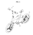
- FIG. 1 is a perspective view illustrating an electric bicycle including an electric bicycle driving apparatus according to a first embodiment of the present invention
- FIG. 2 is a block diagram illustrating the configuration of the electric bicycle driving apparatus according to the first embodiment of the present invention.
- FIG. 3 is an equivalent circuit diagram illustrating an example of the electric bicycle driving apparatus according to the first embodiment of the present invention.
- the electric bicycle driving apparatus according to the first embodiment of the present invention, denoted by reference numeral 100, is provided at one side and the other side of the electric bicycle, denoted by reference numeral 10.
- the electric bicycle driving apparatus 100 includes a speed change mode operator 101, controller 103, generation-signal provider 105, motor-driver operating-signal regulator 107, and motor driver 108.
- the speed change mode operator 101 is provided to output a low-speed mode signal or a high-speed mode signal.
- the speed change mode operator 101 may be provided at a portion of a handle bar of the electric bicycle 10.
- the controller 103 receives the low-speed mode signal or high-speed mode signal output from the speed change mode operator 101, and outputs a first control signal corresponding to the low-speed mode signal or a second control signal corresponding to the high-speed mode signal.
- the controller 103 may include an Electronic Controller Unit (ECU) or a Micro Controller Unit (MCU).
- ECU Electronic Controller Unit
- MCU Micro Controller Unit
- the generation-signal provider 105 is provided to provide a generation signal output from a generator 104.
- the generation-signal provider 105 may include a generation-signal rectification part 105a and a generation-signal storage part 105b.
- the generation-signal rectification part 105a may be electrically connected to the generator 104 to rectify the generation signal output from the generator 104.
- the generation-signal rectification part 105a may include more than one second rectifying diode D2 and D3, more than one fourth rectifying diode D4 and D5, and more than one sixth rectifying diode D6 and D7.
- the more than one second rectifying diode D2 and D3 may be electrically connected to one side of the generator 104, and the more than one fourth rectifying diode D4 and D5 may be electrically connected to another side of the generator 104.
- the more than one second rectifying diode D2 and D3 may include a second rectifying diode D2 and a third rectifying diode D3 connected to each other in series.
- the more than one fourth rectifying diode D4 and D5 may include a fourth rectifying diode D4 and a fifth rectifying diode D5 connected to each other in series.
- the more than one sixth rectifying diode D6 and D7 may be electrically connected to the other side of the generator 104.
- the more than one sixth rectifying diodes D6 and D7 may include a sixth rectifying diode D6 and a seventh rectifying diode D7 connected to each other in series.
- the generation-signal storage part 105b may be electrically connected to the generation-signal rectification part 105a to store the generation signal rectified in the generation-signal rectification part 105a.
- the generation-signal storage part 105b may include more than one second capacitor C2, C3 and C4, which is electrically connected to the generation-signal rectification part 105a and the motor-driver operating-signal regulator 107 that will be described hereinafter.
- the more than one second capacitor C2, C3 and C4 may include a second capacitor C2, a third capacitor C3, and a fourth capacitor C4 connected to one another in series.
- the more than one second capacitor C2, C3 and C4 may be a smoothing capacitor.
- the motor-driver operating-signal regulator 107 receives a first control signal or second control signal when the speed change mode operator 101 outputs a low-speed mode signal or high-speed mode signal, regulates a level of generation signal output from the generation-signal provider 105, and applies the resulting signal to the motor driver 108 that drives a motor 110.
- the motor-driver operating-signal regulator 107 provides a lowered level of the generation signal to the motor driver 108 that is operated upon receiving power of a battery 106 and cuts off an abnormal signal from the motor driver 108.
- the motor driver 108 may be a three-phase motor driver.
- the motor-driver operating-signal regulator 107 may include a first switching device SW1, more than one first resistor R1 and R2, more than one third resistor R3, more than one fourth resistor R4, R5 and R6, and a second switching device SW2.
- the first switching device SW1 may be electrically connected to one side of the controller 103, and the more than one first resistor R1 and R2 may be electrically connected to the other side of the controller 103 and first switching device SW1.
- the more than one first resistor R1 and R2 may include a first resistor R1 and a second resistor R2 for partial pressure.
- the first switching device SW1 may include at least one of a Metal-Oxide Semiconductor Field Effect Transistor (MOSFET) and a Bipolar Junction Transistor (BJT).
- MOSFET Metal-Oxide Semiconductor Field Effect Transistor
- BJT Bipolar Junction Transistor
- the more than one third resistor R3 may be electrically connected to the first switching device SW1, motor driver 108 and battery 106.
- the more than one fourth resistor R4, R5 and R6 may be electrically connected to the more than one third resistor R3 and first switching device SW1.
- the second switching device SW2 may be electrically connected to the generation-signal provider 105 and the more than one fourth resistor R4, R5 and R6.
- the more than one fourth resistor R4, R5 and R6 may include a fourth resistor R4, fifth resistor R5 and sixth resistor R6 for partial pressure.
- the second switching device SW2 may include at least one of an MOSFET and a BJT.
- the second switching device SW2 may include more than one zener diode ZD2, which is electrically connected to the generation-signal provider 105 and the more than one fourth resistor R4, R5 and R6 to cut off an abnormal signal from the first switching device SW1.
- the motor-driver operating-signal regulator 107 may further include more than one zener diode ZD1, which is electrically connected to the generation-signal provider 105 and the more than one fourth resistor R4, R5 and R6 to cut off an abnormal signal from the first switching device SW1.
- the more than one zener diode ZD1 is electrically connected to the generation-signal provider 105 and one resistor R6 among the more than one fourth resistor R4, R5 and R6 to cut off an abnormal signal from the first switching device SW1.
- the motor-driver operating-signal regulator 107 creates a first current-path between the more than one third resistor R3 and the more than one fourth resistor R4, R5 and R6.
- the motor-driver operating-signal regulator 107 receives a first control signal or second control signal from the controller 103, turning on the first switching device SW1.
- the motor-driver operating-signal regulator 107 also creates a second current-path between the more than one third resistor R3 and the more than one fourth resistor R4, R5 and R6 to thereby turn on the second switching device SW2.
- the motor-driver operating-signal regulator 107 may regulate the level of generation signal from the generation-signal provider 105 via the more than one third resistor R3 and the more than one fourth resistor R4, R5 and R6, so as to lower the level of generation signal to be transmitted to the motor driver 108 that is operated upon receiving power of the battery 106.
- the motor-driver operating-signal regulator 107 may temporarily turn off the first switching device SW1 to prevent an abnormal signal transmitted from the motor driver 108 from being transmitted to at least one of the generator 104 and the motor driver 108 via the more than one third resistor R3 that is electrically connected to the first switching device SW1.
- the more than one capacitor C1 may be electrically connected to the second switching device SW2, more than one third resistor R3 and battery 106.
- the more than one capacitor C1 may be a smoothing capacitor.
- the more than one capacitor C1 may temporarily store the regulated generation signal, and then provide the signal to the motor 110 at an operating time of the motor driver 108.
- the more than one capacitor C1 may remove a noise signal from the regulated generation signal, and provide the resulting signal to the motor 110.
- More than one rectifying diode D1 may be electrically connected to the second switching device SW2, more than one capacitor C1 and battery 106, to rectify power output from the battery 106 and apply the power to the motor driver 108.
- the method to drive the electric bicycle 10 using the electric bicycle driving apparatus 100 includes outputting a low-speed mode signal or high-speed mode signal from the speed change mode operator 101.
- the method to drive the electric bicycle 10 using the electric bicycle driving apparatus 100 includes receiving a first control signal or second control signal transmitted from the controller 103 to the motor-driver operating-signal regulator 107 when the speed change mode operator 101 outputs a low-speed mode signal or high-speed mode signal, lowering a level of generation signal output from the generation-signal provider 105 using the motor-driver operating-signal regulator 107, and driving the motor 110 based on the lowered level of generation signal using the motor driver 108 that is operated upon receiving power of the battery 106.
- the method to drive the electric bicycle 10 using the electric bicycle driving apparatus 100 according to the first embodiment of the present invention includes cutting off an abnormal signal from the motor driver 108 using the motor-driver operating-signal regulator 107.
- the electric bicycle driving apparatus 100 includes the speed change mode operator 101, controller 103, generation-signal provider 105, motor-driver operating-signal regulator 107, and motor driver 108.
- the electric bicycle driving apparatus 100 may lower the level of generation signal to provide the resulting signal to the motor driver 108 that is operated upon receiving power of the battery 106, which may result in a reduction in battery power consumption.
- the electric bicycle driving apparatus 100 may cut off an abnormal signal from the motor driver 108, which may prevent malfunction and stabilize drive properties of the electric bicycle.
- FIG. 4 is a perspective view illustrating an electric bicycle including an electric bicycle driving apparatus according to a second embodiment of the present invention
- FIG. 5 is a block diagram illustrating the configuration of the electric bicycle driving apparatus according to the second embodiment of the present invention.
- FIG. 6 is an equivalent circuit diagram illustrating an example of the electric bicycle driving apparatus according to the second embodiment of the present invention.
- an electric bicycle driving apparatus 400 according to the second embodiment of the present invention is provided at either side of the electric bicycle 10.
- the electric bicycle driving apparatus 400 includes the speed change mode operator 101, controller 403, generation-signal provider 105, motor-driver operating-signal regulator 107, motor-driver operating-signal sensor 409, motor-driver operating-signal decider 411, display 413, and alarm 415.
- the speed change mode operator 101 outputs a low-speed mode signal or high-speed mode signal.
- the speed change mode operator 101 may be installed to the handle of the electric bicycle 10.
- the controller 103 receives the low-speed mode signal or high-speed mode signal output from the speed change mode operator 101, and outputs a first control signal corresponding to the low-speed mode signal or a second control signal corresponding to the high-speed mode signal.
- the controller 103 may include an ECU or an MCU.
- the generation-signal provider 105 is for provision of a generation signal output from the generator 104.
- the generation-signal provider 105 may include the generation-signal rectification part 105a and the generation-signal storage part 105b.
- the generation-signal rectification part 105a may be electrically connected to the generator 104 to rectify the generation signal output from the generator 104.
- the generation-signal rectification part 105a may include the more than one second rectifying diode D2 and D3, more than one fourth rectifying diode D4 and D5, and more than one sixth rectifying diode D6 and D7.
- the more than one second rectifying diode D2 and D3 may be electrically connected to one side of the generator 104, and the more than one fourth rectifying diode D4 and D5 may be electrically connected to another side of the generator 104.
- the more than one second rectifying diode D2 and D3 may include the second rectifying diode D2 and third rectifying diode D3 connected to each other in series.
- the more than one fourth rectifying diode D4 and D5 may include the fourth rectifying diode D4 and fifth rectifying diode D5 connected to each other in series.
- the more than one sixth rectifying diode D6 and D7 may be electrically connected to the other side of the generator 104.
- the more than one sixth rectifying diode D6 and D7 may include the sixth rectifying diode D6 and seventh rectifying diode D7 connected to each other in series.
- the generation-signal storage part 105b may be electrically connected to the generation-signal rectification part 105a to store the generation signal rectified in the generation-signal rectification part 105a.
- the generation-signal storage part 105b may include more than one second capacitor C2, C3 and C4, which is electrically connected to the generation-signal rectification part 105a and the motor-driver operating-signal regulator 107 that will be described hereinafter.
- the more than one second capacitor C2, C3 and C4 may include the second capacitor C2, third capacitor C3, and fourth capacitor C4 connected to one another in series.
- the more than one second capacitor C2, C3 and C4 may be a smoothing capacitor.
- the motor-driver operating-signal regulator 107 receives a first control signal or second control signal when the speed change mode operator 101 outputs a low-speed mode signal or high-speed mode signal, regulates a level of generation signal output from the generation-signal provider 105, and applies the resulting signal to the motor driver 108 that drives a motor 110.
- the motor-driver operating-signal regulator 107 provides a lowered level of the generation signal to the motor driver 108 that is operated upon receiving power of a battery 106 and cuts off an abnormal signal from the motor driver 108.
- the motor driver 108 may be a three-phase motor driver.
- the motor-driver operating-signal regulator 107 may include the first switching device SW1, more than one first resistor R1 and R2, more than one third resistor R3, more than one fourth resistor R4, R5 and R6, and second switching device SW2.
- the first switching device SW1 may be electrically connected to one side of the controller 103, and the more than one first resistor R1 and R2 may be electrically connected to the other side of the controller 103 and the first switching device SW1.
- the more than one first resistor R1 and R2 may include the first resistor R1 and second resistor R2 for partial pressure.
- the first switching device SW1 may include at least one of an MOSFET and a BJT.
- the more than one third resistor R3 may be electrically connected to the first switching device SW1, motor driver 108 and battery 106.
- the more than one fourth resistor R4, R5 and R6 may be electrically connected to the more than one third resistor R3 and first switching device SW1.
- the second switching device SW2 may be electrically connected to the generation-signal provider 105 and the more than one fourth resistor R4, R5 and R6.
- the more than one fourth resistor R4, R5 and R6 may include the fourth resistor R4, fifth resistor R5 and sixth resistor R6 for partial pressure.
- the second switching device SW2 may include at least one of an MOSFET and a BJT.
- the second switching device SW2 may include more than one zener diode ZD2, which is electrically connected to the generation-signal provider 105 and the more than one fourth resistors R4, R5 and R6 to cut off an abnormal signal from the first switching device SW1.
- the motor-driver operating-signal regulator 107 may further include more than one zener diode ZD1, which is electrically connected to the generation-signal provider 105 and the more than one fourth resistors R4, R5 and R6 to cut off an abnormal signal from the first switching device SW1.
- the more than one zener diode ZD1 is electrically connected to the generation-signal provider 105 and one resistor R6 among the more than one fourth resistor R4, R5 and R6 to cut off an abnormal signal transmitted from the first switching device SW1.
- the motor-driver operating-signal regulator 107 creates a first current-path between the more than one third resistor R3 and the more than one fourth resistor R4, R5 and R6.
- the motor-driver operating-signal regulator 107 receives a first control signal or second control signal from the controller 103, turning on the first switching device SW1.
- the motor-driver operating-signal regulator 107 also creates a second current-path between the more than one third resistor R3 and the more than one fourth resistor R4, R5 and R6 to thereby turn on the second switching device SW2.
- the motor-driver operating-signal regulator 107 may regulate the level of generation signal from the generation-signal provider 105 via the more than one third resistor R3 and the more than one fourth resistor R4, R5 and R6, so as to lower the level of generation signal to be transmitted to the motor driver 108 that is operated upon receiving power of the battery 106.
- the motor-driver operating-signal regulator 107 may temporarily turn off the first switching device SW1 to prevent an abnormal signal transmitted from the motor driver 108 from being transmitted to at least one of the generator 104 and motor driver 108 via the more than one third resistor R3 that is electrically connected to the first switching device SW1.
- the more than one capacitor C1 may be electrically connected to the second switching device SW2, more than one third resistor R3 and battery 106.
- the more than one capacitor C1 may be a smoothing capacitor.
- the more than one capacitor C1 may temporarily store the regulated generation signal, and then provide the signal to the motor 110 at an operating time of the motor driver 108.
- the more than one capacitor C1 may remove a noise signal from the regulated generation signal, and provide the resulting signal to the motor 110.
- the more than one rectifying diode D1 may be electrically connected to the second switching device SW2, more than one capacitor C1 and battery 106, to rectify power output from the battery 106 and apply the power to the motor driver 108.
- the motor-driver operating-signal sensor 409 may be electrically connected to the motor-driver operating-signal regulator 107 and the motor driver 108, and serve to sense a current operating signal for the motor driver 108 output from the motor-driver operating-signal regulator 107.
- the motor-driver operating-signal sensor 409 may include a current sensor (not shown) or a voltage sensor (not shown) to detect the operating signal for the motor driver 108.
- the controller 403 may contain a preset reference range of the operating signal for the motor driver 108.
- the motor-driver operating-signal decider 411 may decide whether or not the current operating signal for the motor driver 108 sensed by the motor-driver operating-signal sensor 409 is within the reference range of the operating signal for the motor driver 108 under control of the controller 403.
- the controller 403 may temporarily stop operation of the motor driver 108.
- the controller 403 may provide a display signal to the display 413.
- the display 413 may include a Human Machine Interface (HMI) module (not shown) to indicate the state of the current operating signal for the motor driver 108 via a HMI message output from the HMI module (not shown).
- HMI Human Machine Interface
- the controller 403 may provide an alarm signal to the alarm 415.
- the alarm 415 may include a speaker (not shown) or an alarm device (not shown) to indicate the state of the current operating signal of the motor driver 108 via voice or alarm sound output from the speaker (not shown) or the alarm device (not shown).
- the method to drive the electric bicycle 10 using the electric bicycle driving apparatus 400 according to the second embodiment of the present invention includes outputting a low-speed mode signal or high-speed mode signal from the speed change mode operator 101.
- the method to drive the electric bicycle 10 using the electric bicycle driving apparatus 400 includes receiving a first control signal or second control signal transmitted from the controller 103 to the motor-driver operating-signal regulator 107 when the speed change mode operator 101 outputs a low-speed mode signal or high-speed mode signal, lowering a level of generation signal output from the generation-signal provider 105 using the motor-driver operating-signal regulator 107, and driving the motor 110 based on the lowered level of generation signal using the motor driver 108 that is operated upon receiving power of the battery 106.
- the method to drive the electric bicycle 10 using the electric bicycle driving apparatus 400 according to the second embodiment of the present invention includes cutting off an abnormal signal from the motor driver 108 using the operating signal regulator 107.
- the method to drive the electric bicycle 10 using the electric bicycle driving apparatus 400 includes sensing a current operating signal for the motor driver 108 output from the motor-driver operating-signal regulator 107 using the motor-driver operating-signal sensor 409.
- the method to drive the electric bicycle 10 using the electric bicycle driving apparatus 400 includes deciding, using the motor-driver operating-signal decider 411 under control of the controller 403, whether or not the current operating signal for the motor driver 108 sensed by the motor-driver operating-signal sensor 409 is within a reference range of the operating signal for the motor driver 108 preset by the controller 403.
- the method to drive the electric bicycle 10 using the electric bicycle driving apparatus 400 includes temporarily stopping operation of the motor driver 108 using the controller 403 if it is decided by the motor-driver operating-signal decider 411 that the current operating signal for the motor driver 108 is not within the reference range of the operating signal for the motor driver 108.
- the method to drive the electric bicycle 10 using the electric bicycle driving apparatus 400 according to the second embodiment of the present invention includes providing a display signal to the display 413 under control of the controller 403 if it is decided by the motor-driver operating-signal decider 411 that the current operating signal for the motor driver 108 is not within the reference range of the operating signal for the motor driver 108.
- the method to drive the electric bicycle 10 using the electric bicycle driving apparatus 400 includes providing an alarm signal to the alarm 415 under control of the controller 403 if it is decided by the motor-driver operating-signal decider 411 that the current operating signal for the motor driver 108 is not within the reference range of the operating signal for the motor driver 108.
- the electric bicycle driving apparatus 400 includes the speed change mode operator 101, controller 103, generation-signal provider 105, motor-driver operating-signal regulator 107, motor driver 108, motor-driver operating-signal sensor 409, and motor-driver operating-signal decider 411.
- the electric bicycle driving apparatus 400 may lower the level of generation signal to provide the resulting signal to the motor driver 108 that is operated upon receiving power of the battery 106, which may result in a reduction in battery power consumption.
- the electric bicycle driving apparatus 400 may cut off an abnormal signal transmitted to the motor driver 108, which may prevent malfunction and stabilize drive properties of the electric bicycle.
- the electric bicycle driving apparatus 400 may temporarily stop operation of the motor driver 108 using the controller 403 if it is decided by the motor-driver operating-signal decider 411 that the current operating signal for the motor driver 108 is not within the reference range of the operating signal for the motor driver 108, and may perform at least one of provision of a display signal to the display 413 and provision of an alarm signal to the alarm 415 under control of the controller 403.
- the electric bicycle driving apparatus 400 may discriminate an abnormal signal transmitted from the motor driver 108 and prevent damage to the motor driver 108 due to an abnormal signal, which results in reduced repair and maintenance time and costs.
Landscapes
- Engineering & Computer Science (AREA)
- Transportation (AREA)
- Mechanical Engineering (AREA)
- Power Engineering (AREA)
- Chemical & Material Sciences (AREA)
- Combustion & Propulsion (AREA)
- Life Sciences & Earth Sciences (AREA)
- Sustainable Development (AREA)
- Sustainable Energy (AREA)
- Electric Propulsion And Braking For Vehicles (AREA)
- Control Of Electric Motors In General (AREA)
Abstract
Description
- Embodiments of the present invention relate to an electric bicycle driving apparatus.
- In general, electric bicycle driving apparatuses are provided to drive electric bicycles.
- Most conventional driving apparatuses for electric bicycles have a limit to effective operation of a motor driver that drives a motor in a low-speed or high-speed motor driving mode, and consequently have a limit to reduction in battery power consumption.
- In addition, conventional electric bicycle driving apparatuses may not function to cut off an abnormal signal from the motor driver, thus having difficulties in preventing malfunction and in stabilizing drive properties of electric bicycles.
- Moreover, such a limit to cutoff of an abnormal signal from the motor driver may cause deterioration of the motor driver due to the abnormal signal, and therefore conventional electric bicycle driving apparatuses may have a difficulty in reducing repair/maintenance time and costs.
- Therefore, it is an aspect of the present invention to provide an electric bicycle driving apparatus which may apply a lowered level of generation signal to a motor driver that is operated upon receiving power of a battery, resulting in a reduction in battery power consumption.
- It is another aspect of the present invention to provide an electric bicycle driving apparatus which may cut off an abnormal signal from a motor driver, thereby preventing malfunction and stabilizing drive properties of the electric bicycle.
- It is a further aspect of the present invention to provide an electric bicycle driving apparatus which may discriminate an abnormal signal and prevent deterioration of a motor driver due to the abnormal signal, thereby achieving reduced repair/maintenance time and costs.
- Additional aspects of the invention will be set forth in part in the description which follows and, in part, will be obvious from the description, or may be learned by practice of the invention.
- In accordance with one aspect of the present invention, an electric bicycle driving apparatus includes a speed change mode operator to output a low-speed mode signal or a high-speed mode signal, a controller to receive the low-speed mode signal or high-speed mode signal output from the speed change mode operator and output a first control signal corresponding to the low-speed mode signal or a second control signal corresponding to the high-speed mode signal, a generation-signal provider to provide a generation signal output from a generator, and a motor-driver operating-signal regulator to receive the first control signal or second control signal when the speed change mode operator outputs the low-speed mode signal or high-speed mode signal, to regulate a level of the generation signal output from the generation-signal provider and to provide the resulting signal to a motor driver that drives a motor, wherein the motor-driver operating-signal regulator provides a lowered level of generation signal to the motor driver that is operated upon receiving power of a battery, and cuts off an abnormal signal transmitted from the motor driver.
- The motor-driver operating-signal regulator may include a first switching device electrically connected to one side of the controller, more than one first resistor electrically connected to another side of the controller and first switching device, more than one third resistor electrically connected to the first switching device, motor driver and battery, more than one fourth resistor electrically connected to the more than one third resistor and first switching device, and a second switching device electrically connected to the generation-signal provider and more than one fourth resistor.
- The more than one first resistor may include a first resistor and a second resistor for partial pressure.
- The more than one fourth resistor may include a fourth resistor, a fifth resistor, and a sixth resistor for partial pressure.
- Each of the first switching device and the second switching device may include at least one of a Metal-Oxide Semiconductor Field Effect Transistor (MOSFET) and a Bipolar Junction Transistor (BJT).
- The motor-driver operating-signal regulator may further include more than one zener diode electrically connected to the generation-signal provider and more than one fourth resistor.
- The second switching device may include more than one zener diode electrically connected to the generation-signal provider and more than one fourth resistor.
- The motor-driver operating-signal regulator may further include more than one capacitor electrically connected to the second switching device, more than one third resistor and battery.
- The more than one capacitor may be a smoothing capacitor.
- The motor-driver operating-signal regulator may further include more than one rectifying diode electrically connected to the second switching device, more than one capacitor and battery.
- The apparatus may further include a motor-driver operating-signal sensor electrically connected to the motor-driver operating-signal regulator and motor driver, the sensor serving to sense a current operating signal for the motor driver output from the motor-driver operating-signal regulator, wherein the controller contains a preset reference range of the operating signal for the motor driver, and a motor-driver operating-signal decider to decide whether or not the current operating signal for the motor driver sensed by the motor-driver operating-signal sensor is within the reference range of the operating signal for the motor driver under control of the controller, wherein the controller temporarily stops operation of the motor driver if the motor-driver operating-signal decider decides that the current operating signal for the motor driver is not within the reference range of the operating signal for the motor driver.
- The controller may provide a display signal to a display if the motor-driver operating-signal decider decides that the current operating signal for the motor driver is not within the reference range of the operating signal for the motor driver.
- The controller may provide an alarm signal to an alarm unit if the motor-driver operating-signal decider decides that the current operating signal for the motor driver is not within the reference range of the operating signal for the motor driver.
- The generation-signal provider may include a generation-signal rectification part electrically connected to the generator to rectify the generation signal output from the generator, and a generation-signal storage part electrically connected to the generation-signal rectification part to store the generation signal rectified in the generation-signal rectification part.
- The generation-signal rectification part may include more than one second rectifying diode electrically connected to one side of the generator, more than one fourth rectifying diode electrically connected to another side of the generator, and more than one sixth rectifying diode electrically connected to the other side of the generator.
- The more than one second rectifying diode may include a second rectifying diode and a third rectifying diode connected to each other in series.
- The more than one fourth rectifying diode may include a fourth rectifying diode and a fifth rectifying diode connected to each other in series.
- The more than one sixth rectifying diode may include a sixth rectifying diode and a seventh rectifying diode connected to each other in series.
- The generation-signal storage part may include more than one second capacitor electrically connected to the generation-signal rectification part and motor-driver operating-signal regulator.
- The more than one second capacitor may include a second capacitor, a third capacitor and a fourth capacitor connected to one another in series.
- The more than one second capacitor may include a smoothing capacitor.
- These and/or other aspects of the invention will become apparent and more readily appreciated from the following description of the embodiments, taken in conjunction with the accompanying drawings of which:
-
FIG. 1 is a perspective view illustrating an electric bicycle including an electric bicycle driving apparatus according to a first embodiment of the present invention; -
FIG. 2 is a block diagram illustrating a configuration of the electric bicycle driving apparatus according to the first embodiment of the present invention; -
FIG. 3 is an equivalent circuit diagram illustrating an example of the electric bicycle driving apparatus according to the first embodiment of the present invention; -
FIG. 4 is a perspective view illustrating an electric bicycle including an electric bicycle driving apparatus according to a second embodiment of the present invention; -
FIG. 5 is a block diagram illustrating the configuration of the electric bicycle driving apparatus according to the second embodiment of the present invention; and -
FIG. 6 is an equivalent circuit diagram of another example of the electric bicycle driving apparatus according to the second embodiment of the present invention. - Reference will now be made in detail to the embodiments of the present invention, examples of which are illustrated in the accompanying drawings, wherein like reference numerals refer to like elements throughout.
-
FIG. 1 is a perspective view illustrating an electric bicycle including an electric bicycle driving apparatus according to a first embodiment of the present invention, andFIG. 2 is a block diagram illustrating the configuration of the electric bicycle driving apparatus according to the first embodiment of the present invention. -
FIG. 3 is an equivalent circuit diagram illustrating an example of the electric bicycle driving apparatus according to the first embodiment of the present invention. - First, referring to
FIG. 1 , the electric bicycle driving apparatus according to the first embodiment of the present invention, denoted byreference numeral 100, is provided at one side and the other side of the electric bicycle, denoted byreference numeral 10. - Next, referring to
FIGS. 2 and3 , the electricbicycle driving apparatus 100 according to the first embodiment of the present invention includes a speedchange mode operator 101,controller 103, generation-signal provider 105, motor-driver operating-signal regulator 107, andmotor driver 108. - The speed
change mode operator 101 is provided to output a low-speed mode signal or a high-speed mode signal. - The speed
change mode operator 101 may be provided at a portion of a handle bar of theelectric bicycle 10. - The
controller 103 receives the low-speed mode signal or high-speed mode signal output from the speedchange mode operator 101, and outputs a first control signal corresponding to the low-speed mode signal or a second control signal corresponding to the high-speed mode signal. - The
controller 103 may include an Electronic Controller Unit (ECU) or a Micro Controller Unit (MCU). - The generation-
signal provider 105 is provided to provide a generation signal output from agenerator 104. - The generation-
signal provider 105 may include a generation-signal rectification part 105a and a generation-signal storage part 105b. - The generation-
signal rectification part 105a may be electrically connected to thegenerator 104 to rectify the generation signal output from thegenerator 104. - The generation-
signal rectification part 105a may include more than one second rectifying diode D2 and D3, more than one fourth rectifying diode D4 and D5, and more than one sixth rectifying diode D6 and D7. - The more than one second rectifying diode D2 and D3 may be electrically connected to one side of the
generator 104, and the more than one fourth rectifying diode D4 and D5 may be electrically connected to another side of thegenerator 104. - The more than one second rectifying diode D2 and D3 may include a second rectifying diode D2 and a third rectifying diode D3 connected to each other in series.
- The more than one fourth rectifying diode D4 and D5 may include a fourth rectifying diode D4 and a fifth rectifying diode D5 connected to each other in series.
- The more than one sixth rectifying diode D6 and D7 may be electrically connected to the other side of the
generator 104. - The more than one sixth rectifying diodes D6 and D7 may include a sixth rectifying diode D6 and a seventh rectifying diode D7 connected to each other in series.
- The generation-
signal storage part 105b may be electrically connected to the generation-signal rectification part 105a to store the generation signal rectified in the generation-signal rectification part 105a. - The generation-
signal storage part 105b may include more than one second capacitor C2, C3 and C4, which is electrically connected to the generation-signal rectification part 105a and the motor-driver operating-signal regulator 107 that will be described hereinafter. - The more than one second capacitor C2, C3 and C4 may include a second capacitor C2, a third capacitor C3, and a fourth capacitor C4 connected to one another in series.
- The more than one second capacitor C2, C3 and C4 may be a smoothing capacitor.
- The motor-driver operating-
signal regulator 107 receives a first control signal or second control signal when the speedchange mode operator 101 outputs a low-speed mode signal or high-speed mode signal, regulates a level of generation signal output from the generation-signal provider 105, and applies the resulting signal to themotor driver 108 that drives amotor 110. The motor-driver operating-signal regulator 107 provides a lowered level of the generation signal to themotor driver 108 that is operated upon receiving power of abattery 106 and cuts off an abnormal signal from themotor driver 108. - The
motor driver 108 may be a three-phase motor driver. - Specifically, the motor-driver operating-
signal regulator 107 may include a first switching device SW1, more than one first resistor R1 and R2, more than one third resistor R3, more than one fourth resistor R4, R5 and R6, and a second switching device SW2. - The first switching device SW1 may be electrically connected to one side of the
controller 103, and the more than one first resistor R1 and R2 may be electrically connected to the other side of thecontroller 103 and first switching device SW1. - The more than one first resistor R1 and R2 may include a first resistor R1 and a second resistor R2 for partial pressure.
- The first switching device SW1 may include at least one of a Metal-Oxide Semiconductor Field Effect Transistor (MOSFET) and a Bipolar Junction Transistor (BJT).
- The more than one third resistor R3 may be electrically connected to the first switching device SW1,
motor driver 108 andbattery 106. - The more than one fourth resistor R4, R5 and R6 may be electrically connected to the more than one third resistor R3 and first switching device SW1. The second switching device SW2 may be electrically connected to the generation-
signal provider 105 and the more than one fourth resistor R4, R5 and R6. - The more than one fourth resistor R4, R5 and R6 may include a fourth resistor R4, fifth resistor R5 and sixth resistor R6 for partial pressure.
- The second switching device SW2 may include at least one of an MOSFET and a BJT.
- The second switching device SW2 may include more than one zener diode ZD2, which is electrically connected to the generation-
signal provider 105 and the more than one fourth resistor R4, R5 and R6 to cut off an abnormal signal from the first switching device SW1. - The motor-driver operating-
signal regulator 107 may further include more than one zener diode ZD1, which is electrically connected to the generation-signal provider 105 and the more than one fourth resistor R4, R5 and R6 to cut off an abnormal signal from the first switching device SW1. - That is, the more than one zener diode ZD1 is electrically connected to the generation-
signal provider 105 and one resistor R6 among the more than one fourth resistor R4, R5 and R6 to cut off an abnormal signal from the first switching device SW1. - The motor-driver operating-
signal regulator 107 creates a first current-path between the more than one third resistor R3 and the more than one fourth resistor R4, R5 and R6. When the speedchange mode operator 101 outputs a low-speed mode signal or high-speed mode signal, the motor-driver operating-signal regulator 107 receives a first control signal or second control signal from thecontroller 103, turning on the first switching device SW1. The motor-driver operating-signal regulator 107 also creates a second current-path between the more than one third resistor R3 and the more than one fourth resistor R4, R5 and R6 to thereby turn on the second switching device SW2. As such, the motor-driver operating-signal regulator 107 may regulate the level of generation signal from the generation-signal provider 105 via the more than one third resistor R3 and the more than one fourth resistor R4, R5 and R6, so as to lower the level of generation signal to be transmitted to themotor driver 108 that is operated upon receiving power of thebattery 106. - On the other hand, the motor-driver operating-
signal regulator 107 may temporarily turn off the first switching device SW1 to prevent an abnormal signal transmitted from themotor driver 108 from being transmitted to at least one of thegenerator 104 and themotor driver 108 via the more than one third resistor R3 that is electrically connected to the first switching device SW1. - The more than one capacitor C1 may be electrically connected to the second switching device SW2, more than one third resistor R3 and
battery 106. - The more than one capacitor C1 may be a smoothing capacitor.
- The more than one capacitor C1 may temporarily store the regulated generation signal, and then provide the signal to the
motor 110 at an operating time of themotor driver 108. - The more than one capacitor C1 may remove a noise signal from the regulated generation signal, and provide the resulting signal to the
motor 110. - More than one rectifying diode D1 may be electrically connected to the second switching device SW2, more than one capacitor C1 and
battery 106, to rectify power output from thebattery 106 and apply the power to themotor driver 108. - Hereinafter, a method to drive the
electric bicycle 10 using the electricbicycle driving apparatus 100 according to the first embodiment of the present invention will be described. - First, the method to drive the
electric bicycle 10 using the electricbicycle driving apparatus 100 according to the first embodiment of the present invention includes outputting a low-speed mode signal or high-speed mode signal from the speedchange mode operator 101. - Thereafter, the method to drive the
electric bicycle 10 using the electricbicycle driving apparatus 100 according to the first embodiment of the present invention includes receiving a first control signal or second control signal transmitted from thecontroller 103 to the motor-driver operating-signal regulator 107 when the speedchange mode operator 101 outputs a low-speed mode signal or high-speed mode signal, lowering a level of generation signal output from the generation-signal provider 105 using the motor-driver operating-signal regulator 107, and driving themotor 110 based on the lowered level of generation signal using themotor driver 108 that is operated upon receiving power of thebattery 106. - At this time, the method to drive the
electric bicycle 10 using the electricbicycle driving apparatus 100 according to the first embodiment of the present invention includes cutting off an abnormal signal from themotor driver 108 using the motor-driver operating-signal regulator 107. - As described above, the electric
bicycle driving apparatus 100 according to the first embodiment of the present invention includes the speedchange mode operator 101,controller 103, generation-signal provider 105, motor-driver operating-signal regulator 107, andmotor driver 108. - Accordingly, the electric
bicycle driving apparatus 100 according to the first embodiment of the present invention may lower the level of generation signal to provide the resulting signal to themotor driver 108 that is operated upon receiving power of thebattery 106, which may result in a reduction in battery power consumption. - Additionally, the electric
bicycle driving apparatus 100 according to the first embodiment of the present invention may cut off an abnormal signal from themotor driver 108, which may prevent malfunction and stabilize drive properties of the electric bicycle. -
FIG. 4 is a perspective view illustrating an electric bicycle including an electric bicycle driving apparatus according to a second embodiment of the present invention, andFIG. 5 is a block diagram illustrating the configuration of the electric bicycle driving apparatus according to the second embodiment of the present invention. -
FIG. 6 is an equivalent circuit diagram illustrating an example of the electric bicycle driving apparatus according to the second embodiment of the present invention. - Referring to
FIG. 4 , an electricbicycle driving apparatus 400 according to the second embodiment of the present invention is provided at either side of theelectric bicycle 10. - Referring to
FIGS. 5 and6 , the electricbicycle driving apparatus 400 according to the second embodiment of the present invention includes the speedchange mode operator 101,controller 403, generation-signal provider 105, motor-driver operating-signal regulator 107, motor-driver operating-signal sensor 409, motor-driver operating-signal decider 411,display 413, andalarm 415. - The speed
change mode operator 101 outputs a low-speed mode signal or high-speed mode signal. - The speed
change mode operator 101 may be installed to the handle of theelectric bicycle 10. - The
controller 103 receives the low-speed mode signal or high-speed mode signal output from the speedchange mode operator 101, and outputs a first control signal corresponding to the low-speed mode signal or a second control signal corresponding to the high-speed mode signal. - The
controller 103 may include an ECU or an MCU. - The generation-
signal provider 105 is for provision of a generation signal output from thegenerator 104. - The generation-
signal provider 105 may include the generation-signal rectification part 105a and the generation-signal storage part 105b. - The generation-
signal rectification part 105a may be electrically connected to thegenerator 104 to rectify the generation signal output from thegenerator 104. - The generation-
signal rectification part 105a may include the more than one second rectifying diode D2 and D3, more than one fourth rectifying diode D4 and D5, and more than one sixth rectifying diode D6 and D7. - The more than one second rectifying diode D2 and D3 may be electrically connected to one side of the
generator 104, and the more than one fourth rectifying diode D4 and D5 may be electrically connected to another side of thegenerator 104. - The more than one second rectifying diode D2 and D3 may include the second rectifying diode D2 and third rectifying diode D3 connected to each other in series.
- The more than one fourth rectifying diode D4 and D5 may include the fourth rectifying diode D4 and fifth rectifying diode D5 connected to each other in series.
- The more than one sixth rectifying diode D6 and D7 may be electrically connected to the other side of the
generator 104. - The more than one sixth rectifying diode D6 and D7 may include the sixth rectifying diode D6 and seventh rectifying diode D7 connected to each other in series.
- The generation-
signal storage part 105b may be electrically connected to the generation-signal rectification part 105a to store the generation signal rectified in the generation-signal rectification part 105a. - The generation-
signal storage part 105b may include more than one second capacitor C2, C3 and C4, which is electrically connected to the generation-signal rectification part 105a and the motor-driver operating-signal regulator 107 that will be described hereinafter. - The more than one second capacitor C2, C3 and C4 may include the second capacitor C2, third capacitor C3, and fourth capacitor C4 connected to one another in series.
- The more than one second capacitor C2, C3 and C4 may be a smoothing capacitor.
- The motor-driver operating-
signal regulator 107 receives a first control signal or second control signal when the speedchange mode operator 101 outputs a low-speed mode signal or high-speed mode signal, regulates a level of generation signal output from the generation-signal provider 105, and applies the resulting signal to themotor driver 108 that drives amotor 110. The motor-driver operating-signal regulator 107 provides a lowered level of the generation signal to themotor driver 108 that is operated upon receiving power of abattery 106 and cuts off an abnormal signal from themotor driver 108. - The
motor driver 108 may be a three-phase motor driver. - Specifically, the motor-driver operating-
signal regulator 107 may include the first switching device SW1, more than one first resistor R1 and R2, more than one third resistor R3, more than one fourth resistor R4, R5 and R6, and second switching device SW2. - The first switching device SW1 may be electrically connected to one side of the
controller 103, and the more than one first resistor R1 and R2 may be electrically connected to the other side of thecontroller 103 and the first switching device SW1. - The more than one first resistor R1 and R2 may include the first resistor R1 and second resistor R2 for partial pressure.
- The first switching device SW1 may include at least one of an MOSFET and a BJT.
- The more than one third resistor R3 may be electrically connected to the first switching device SW1,
motor driver 108 andbattery 106. - The more than one fourth resistor R4, R5 and R6 may be electrically connected to the more than one third resistor R3 and first switching device SW1. The second switching device SW2 may be electrically connected to the generation-
signal provider 105 and the more than one fourth resistor R4, R5 and R6. - The more than one fourth resistor R4, R5 and R6 may include the fourth resistor R4, fifth resistor R5 and sixth resistor R6 for partial pressure.
- The second switching device SW2 may include at least one of an MOSFET and a BJT.
- The second switching device SW2 may include more than one zener diode ZD2, which is electrically connected to the generation-
signal provider 105 and the more than one fourth resistors R4, R5 and R6 to cut off an abnormal signal from the first switching device SW1. - The motor-driver operating-
signal regulator 107 may further include more than one zener diode ZD1, which is electrically connected to the generation-signal provider 105 and the more than one fourth resistors R4, R5 and R6 to cut off an abnormal signal from the first switching device SW1. - That is, the more than one zener diode ZD1 is electrically connected to the generation-
signal provider 105 and one resistor R6 among the more than one fourth resistor R4, R5 and R6 to cut off an abnormal signal transmitted from the first switching device SW1. - The motor-driver operating-
signal regulator 107 creates a first current-path between the more than one third resistor R3 and the more than one fourth resistor R4, R5 and R6. When the speedchange mode operator 101 outputs a low-speed mode signal or high-speed mode signal, the motor-driver operating-signal regulator 107 receives a first control signal or second control signal from thecontroller 103, turning on the first switching device SW1. The motor-driver operating-signal regulator 107 also creates a second current-path between the more than one third resistor R3 and the more than one fourth resistor R4, R5 and R6 to thereby turn on the second switching device SW2. As such, the motor-driver operating-signal regulator 107 may regulate the level of generation signal from the generation-signal provider 105 via the more than one third resistor R3 and the more than one fourth resistor R4, R5 and R6, so as to lower the level of generation signal to be transmitted to themotor driver 108 that is operated upon receiving power of thebattery 106. - On the other hand, the motor-driver operating-
signal regulator 107 may temporarily turn off the first switching device SW1 to prevent an abnormal signal transmitted from themotor driver 108 from being transmitted to at least one of thegenerator 104 andmotor driver 108 via the more than one third resistor R3 that is electrically connected to the first switching device SW1. - The more than one capacitor C1 may be electrically connected to the second switching device SW2, more than one third resistor R3 and
battery 106. - The more than one capacitor C1 may be a smoothing capacitor.
- The more than one capacitor C1 may temporarily store the regulated generation signal, and then provide the signal to the
motor 110 at an operating time of themotor driver 108. - The more than one capacitor C1 may remove a noise signal from the regulated generation signal, and provide the resulting signal to the
motor 110. - The more than one rectifying diode D1 may be electrically connected to the second switching device SW2, more than one capacitor C1 and
battery 106, to rectify power output from thebattery 106 and apply the power to themotor driver 108. - The motor-driver operating-
signal sensor 409 may be electrically connected to the motor-driver operating-signal regulator 107 and themotor driver 108, and serve to sense a current operating signal for themotor driver 108 output from the motor-driver operating-signal regulator 107. - The motor-driver operating-
signal sensor 409 may include a current sensor (not shown) or a voltage sensor (not shown) to detect the operating signal for themotor driver 108. - The
controller 403 may contain a preset reference range of the operating signal for themotor driver 108. The motor-driver operating-signal decider 411 may decide whether or not the current operating signal for themotor driver 108 sensed by the motor-driver operating-signal sensor 409 is within the reference range of the operating signal for themotor driver 108 under control of thecontroller 403. - If it is decided by the motor-driver operating-
signal decider 411 that the current operating signal for themotor driver 108 is not within the reference range of the operating signal for themotor driver 108, thecontroller 403 may temporarily stop operation of themotor driver 108. - In this case, if it is decided by the motor-driver operating-
signal decider 411 that the current operating signal for themotor driver 108 sensed by the motor-driver operating-signal sensor 409 is not within the reference range of the operating signal for themotor driver 108, thecontroller 403 may provide a display signal to thedisplay 413. - The
display 413 may include a Human Machine Interface (HMI) module (not shown) to indicate the state of the current operating signal for themotor driver 108 via a HMI message output from the HMI module (not shown). - If it is decided by the motor-driver operating-
signal decider 411 that the current operating signal for themotor driver 108 is not within the reference range of the operating signal for themotor driver 108, thecontroller 403 may provide an alarm signal to thealarm 415. - The
alarm 415 may include a speaker (not shown) or an alarm device (not shown) to indicate the state of the current operating signal of themotor driver 108 via voice or alarm sound output from the speaker (not shown) or the alarm device (not shown). - Hereinafter, a method to drive the
electric bicycle 10 using the electricbicycle driving apparatus 400 according to the second embodiment of the present invention will be described. - First, the method to drive the
electric bicycle 10 using the electricbicycle driving apparatus 400 according to the second embodiment of the present invention includes outputting a low-speed mode signal or high-speed mode signal from the speedchange mode operator 101. - Thereafter, the method to drive the
electric bicycle 10 using the electricbicycle driving apparatus 400 according to the second embodiment of the present invention includes receiving a first control signal or second control signal transmitted from thecontroller 103 to the motor-driver operating-signal regulator 107 when the speedchange mode operator 101 outputs a low-speed mode signal or high-speed mode signal, lowering a level of generation signal output from the generation-signal provider 105 using the motor-driver operating-signal regulator 107, and driving themotor 110 based on the lowered level of generation signal using themotor driver 108 that is operated upon receiving power of thebattery 106. - The method to drive the
electric bicycle 10 using the electricbicycle driving apparatus 400 according to the second embodiment of the present invention includes cutting off an abnormal signal from themotor driver 108 using theoperating signal regulator 107. - Thereafter, the method to drive the
electric bicycle 10 using the electricbicycle driving apparatus 400 according to the second embodiment of the present invention includes sensing a current operating signal for themotor driver 108 output from the motor-driver operating-signal regulator 107 using the motor-driver operating-signal sensor 409. - Thereafter, the method to drive the
electric bicycle 10 using the electricbicycle driving apparatus 400 according to the second embodiment of the present invention includes deciding, using the motor-driver operating-signal decider 411 under control of thecontroller 403, whether or not the current operating signal for themotor driver 108 sensed by the motor-driver operating-signal sensor 409 is within a reference range of the operating signal for themotor driver 108 preset by thecontroller 403. - Thereafter, the method to drive the
electric bicycle 10 using the electricbicycle driving apparatus 400 according to the second embodiment of the present invention includes temporarily stopping operation of themotor driver 108 using thecontroller 403 if it is decided by the motor-driver operating-signal decider 411 that the current operating signal for themotor driver 108 is not within the reference range of the operating signal for themotor driver 108. - In this case, the method to drive the
electric bicycle 10 using the electricbicycle driving apparatus 400 according to the second embodiment of the present invention includes providing a display signal to thedisplay 413 under control of thecontroller 403 if it is decided by the motor-driver operating-signal decider 411 that the current operating signal for themotor driver 108 is not within the reference range of the operating signal for themotor driver 108. - Additionally, the method to drive the
electric bicycle 10 using the electricbicycle driving apparatus 400 according to the second embodiment of the present invention includes providing an alarm signal to thealarm 415 under control of thecontroller 403 if it is decided by the motor-driver operating-signal decider 411 that the current operating signal for themotor driver 108 is not within the reference range of the operating signal for themotor driver 108. - As described above, the electric
bicycle driving apparatus 400 according to the second embodiment of the present invention includes the speedchange mode operator 101,controller 103, generation-signal provider 105, motor-driver operating-signal regulator 107,motor driver 108, motor-driver operating-signal sensor 409, and motor-driver operating-signal decider 411. - Accordingly, the electric
bicycle driving apparatus 400 according to the second embodiment of the present invention may lower the level of generation signal to provide the resulting signal to themotor driver 108 that is operated upon receiving power of thebattery 106, which may result in a reduction in battery power consumption. - Additionally, the electric
bicycle driving apparatus 400 according to the second embodiment of the present invention may cut off an abnormal signal transmitted to themotor driver 108, which may prevent malfunction and stabilize drive properties of the electric bicycle. - Moreover, the electric
bicycle driving apparatus 400 according to the second embodiment of the present invention may temporarily stop operation of themotor driver 108 using thecontroller 403 if it is decided by the motor-driver operating-signal decider 411 that the current operating signal for themotor driver 108 is not within the reference range of the operating signal for themotor driver 108, and may perform at least one of provision of a display signal to thedisplay 413 and provision of an alarm signal to thealarm 415 under control of thecontroller 403. - In this way, the electric
bicycle driving apparatus 400 according to the second embodiment of the present invention may discriminate an abnormal signal transmitted from themotor driver 108 and prevent damage to themotor driver 108 due to an abnormal signal, which results in reduced repair and maintenance time and costs. - Although a few embodiments of the present invention have been shown and described, it would be appreciated by those skilled in the art that changes may be made in these embodiments without departing from the principles and spirit of the invention, the scope of which is defined in the claims and their equivalents.
Claims (15)
- An electric bicycle driving apparatus comprising:a speed change mode operator to output a low-speed mode signal or a high-speed mode signal;a controller to receive the low-speed mode signal or high-speed mode signal output from the speed change mode operator and output a first control signal corresponding to the low-speed mode signal or a second control signal corresponding to the high-speed mode signal;a generation-signal provider to provide a generation signal output from a generator; anda motor-driver operating-signal regulator to receive the first control signal or second control signal when the speed change mode operator outputs the low-speed mode signal or high-speed mode signal, to regulate a level of the generation signal output from the generation-signal provider and to provide the resulting signal to a motor driver that drives a motor, wherein the motor-driver operating-signal regulator provides a lowered level of generation signal to the motor driver that is operated upon receiving power of a battery, and cuts off an abnormal signal transmitted from the motor driver.
- The apparatus according to claim 1, wherein the motor-driver operating-signal regulator includes:a first switching device electrically connected to one side of the controller;more than one first resistor electrically connected to another side of the controller and first switching device;more than one third resistor electrically connected to the first switching device, motor driver and battery;more than one fourth resistor electrically connected to the more than one third resistor and first switching device; anda second switching device electrically connected to the generation-signal provider and more than one fourth resistor.
- The apparatus according to claim 2, wherein the more than one first resistor includes a first resistor and a second resistor for partial pressure.
- The apparatus according to claim 2, wherein the more than one fourth resistor includes a fourth resistor, a fifth resistor, and a sixth resistor for partial pressure.
- The apparatus according to claim 2, wherein the motor-driver operating-signal regulator further includes more than one capacitor electrically connected to the second switching device, more than one third resistor and battery.
- The apparatus according to claim 1, further comprising:a motor-driver operating-signal sensor electrically connected to the motor-driver operating-signal regulator and motor driver, the sensor serving to sense a current operating signal for the motor driver output from the motor-driver operating-signal regulator,
wherein the controller contains a preset reference range of the operating signal for the motor driver; anda motor-driver operating-signal decider to decide whether or not the current operating signal for the motor driver sensed by the motor-driver operating-signal sensor is within the reference range of the operating signal for the motor driver under control of the controller,
wherein the controller temporarily stops operation of the motor driver if the motor-driver operating-signal decider decides that the current operating signal for the motor driver is not within the reference range of the operating signal for the motor driver. - The apparatus according to claim 6, wherein the controller provides a display signal to a display if the motor-driver operating-signal decider decides that the current operating signal for the motor driver is not within the reference range of the operating signal for the motor driver.
- The apparatus according to claim 6, wherein the controller provides an alarm signal to an alarm unit if the motor-driver operating-signal decider decides that the current operating signal for the motor driver is not within the reference range of the operating signal for the motor driver.
- The apparatus according to claim 1, wherein the generation-signal provider includes:a generation-signal rectification part electrically connected to the generator to rectify the generation signal output from the generator; anda generation-signal storage part electrically connected to the generation-signal rectification part to store the generation signal rectified in the generation-signal rectification part.
- The apparatus according to claim 9, wherein the generation-signal rectification part includes:more than one second rectifying diode electrically connected to one side of the generator;more than one fourth rectifying diode electrically connected to another side of the generator; andmore than one sixth rectifying diode electrically connected to the other side of the generator.
- The apparatus according to claim 10, wherein the more than one second rectifying diode includes a second rectifying diode and a third rectifying diode connected to each other in series.
- The apparatus according to claim 10, wherein the more than one fourth rectifying diode includes a fourth rectifying diode and a fifth rectifying diode connected to each other in series.
- The apparatus according to claim 10, wherein the more than one sixth rectifying diode includes a sixth rectifying diode and a seventh rectifying diode connected to each other in series.
- The apparatus according to claim 9, wherein the generation-signal storage part includes more than one second capacitor electrically connected to the generation-signal rectification part and motor-driver operating-signal regulator.
- The apparatus according to claim 14, wherein the more than one second capacitor includes a second capacitor, a third capacitor and a fourth capacitor connected to one another in series.
Applications Claiming Priority (1)
| Application Number | Priority Date | Filing Date | Title |
|---|---|---|---|
| KR1020120104168A KR101309514B1 (en) | 2012-09-19 | 2012-09-19 | Apparatus for driving electric bicycle |
Publications (2)
| Publication Number | Publication Date |
|---|---|
| EP2711239A2 true EP2711239A2 (en) | 2014-03-26 |
| EP2711239A3 EP2711239A3 (en) | 2017-10-11 |
Family
ID=47221139
Family Applications (1)
| Application Number | Title | Priority Date | Filing Date |
|---|---|---|---|
| EP12190224.1A Withdrawn EP2711239A3 (en) | 2012-09-19 | 2012-10-26 | Electric bicycle driving apparatus |
Country Status (4)
| Country | Link |
|---|---|
| US (1) | US9083270B2 (en) |
| EP (1) | EP2711239A3 (en) |
| KR (1) | KR101309514B1 (en) |
| CN (1) | CN103661764B (en) |
Families Citing this family (6)
| Publication number | Priority date | Publication date | Assignee | Title |
|---|---|---|---|---|
| KR20140038048A (en) * | 2012-09-19 | 2014-03-28 | 주식회사 만도 | Eletric bicycle and control method thereof |
| KR101532776B1 (en) * | 2013-11-26 | 2015-06-30 | 주식회사 만도 | Chainless eletric bicycle |
| US9502999B2 (en) * | 2014-06-27 | 2016-11-22 | Iucf-Hyu (Industry-University Cooperation Foundation Hanyang University) | Apparatus for driving motor and controlling method thereof |
| CN108820119A (en) * | 2018-06-29 | 2018-11-16 | 北京巧骐科技有限公司 | One kind is ridden foot pedal load control system |
| KR102676489B1 (en) * | 2021-10-21 | 2024-06-19 | 에이치엘만도 주식회사 | Driving apparatus for electric bicycle and controlling method of electric bicycle |
| KR102951861B1 (en) | 2024-01-26 | 2026-04-13 | 에이치엘만도 주식회사 | Method and system for controlling motor of electric bicycle |
Family Cites Families (20)
| Publication number | Priority date | Publication date | Assignee | Title |
|---|---|---|---|---|
| US4096422A (en) * | 1975-12-03 | 1978-06-20 | E. I. Du Pont De Nemours And Company | Motor control system |
| DE3218594A1 (en) * | 1982-05-17 | 1983-12-22 | Braun Ag, 6000 Frankfurt | ELECTRONIC SWITCHING POWER SUPPLY |
| JPH0833302A (en) * | 1994-07-20 | 1996-02-02 | Yoshihiro Onishi | Bicycle with dc motor, direct drive dc three-phase brushless motor and driver therefor |
| TW404383U (en) * | 1995-02-28 | 2000-09-01 | Sanyo Electric Co | Electric bicycle |
| TW364070B (en) * | 1997-12-17 | 1999-07-11 | Fuji Photo Film Kk | Lens-fitted photo film unit and flash device |
| JP2001008480A (en) * | 1999-06-18 | 2001-01-12 | Sankyo Seiki Mfg Co Ltd | Speed controller for motor |
| JP2001122183A (en) * | 1999-10-25 | 2001-05-08 | Yamaha Motor Co Ltd | Self-propelled prevention device for electric assist vehicle |
| US6396137B1 (en) * | 2000-03-15 | 2002-05-28 | Kevin Mark Klughart | Integrated voltage/current/power regulator/switch system and method |
| US6794836B2 (en) * | 2001-02-06 | 2004-09-21 | Invacare Corporation | Electric motor drive controller with voltage control circuit operative in different modes |
| KR200235877Y1 (en) | 2001-03-28 | 2001-10-10 | 아이에스모터코리아주식회사 | Apparatus for controling a bldc motor |
| US7016203B2 (en) * | 2003-01-24 | 2006-03-21 | Virginia Tech Intellectual Properties, Inc. | Self-driven circuit for synchronous rectifier DC/DC converter |
| JP2006015887A (en) * | 2004-07-02 | 2006-01-19 | Sanyo Electric Co Ltd | Motor-assisted bicycle |
| JP4747819B2 (en) * | 2005-12-09 | 2011-08-17 | 富士ゼロックス株式会社 | Motor control device |
| EP2008860B1 (en) * | 2007-06-25 | 2015-06-17 | Mazda Motor Corporation | Control for hybrid electric vehicle |
| JP4946854B2 (en) * | 2007-06-25 | 2012-06-06 | マツダ株式会社 | Control device and control method for hybrid vehicle |
| CN201338543Y (en) * | 2008-12-05 | 2009-11-04 | 无锡机电高等职业技术学校 | Novel electric bicycle controller |
| GB0902356D0 (en) * | 2009-02-12 | 2009-04-01 | Nexxtdrive Ltd | Bicycle transmission systems |
| KR20110023238A (en) * | 2009-08-31 | 2011-03-08 | 주식회사 만도 | Electric bicycle and its control method |
| KR20110033622A (en) * | 2009-09-25 | 2011-03-31 | 주식회사 만도 | Electric bicycle and its control method |
| US20120202649A1 (en) * | 2011-02-07 | 2012-08-09 | Clarkson University | Pedal generator electric bicycle |
-
2012
- 2012-09-19 KR KR1020120104168A patent/KR101309514B1/en active Active
- 2012-10-26 EP EP12190224.1A patent/EP2711239A3/en not_active Withdrawn
- 2012-11-21 US US13/683,268 patent/US9083270B2/en active Active
- 2012-12-18 CN CN201210552261.5A patent/CN103661764B/en active Active
Non-Patent Citations (1)
| Title |
|---|
| None |
Also Published As
| Publication number | Publication date |
|---|---|
| CN103661764B (en) | 2016-11-23 |
| US9083270B2 (en) | 2015-07-14 |
| CN103661764A (en) | 2014-03-26 |
| EP2711239A3 (en) | 2017-10-11 |
| US20140077740A1 (en) | 2014-03-20 |
| KR101309514B1 (en) | 2013-10-14 |
Similar Documents
| Publication | Publication Date | Title |
|---|---|---|
| EP2711239A2 (en) | Electric bicycle driving apparatus | |
| EP2264884B1 (en) | Inverter device | |
| JP6967750B2 (en) | Motor control device and control method of motor control device | |
| JP5630474B2 (en) | Inverter | |
| US8736234B2 (en) | Power converter control apparatus | |
| JP2011205746A (en) | Discharge control apparatus | |
| EP2711238A2 (en) | Electric bicycle driving apparatus | |
| JP2019193384A (en) | Drive device for semiconductor element | |
| CN102055393A (en) | Motor control apparatus | |
| CN110022116B (en) | Motor control device and control method for motor control device | |
| US20070040532A1 (en) | Motor controller and control method thereof, and error detecting apparatus of inverter | |
| KR102036115B1 (en) | Air conditioner having function of protecting compressor | |
| CN105324934B (en) | Dual Power Mode Drive | |
| JP2008005647A (en) | Inverter control method | |
| JP2021097476A (en) | Motor drive device having protection mechanism | |
| JP5778094B2 (en) | Electric work vehicle, battery device thereof, and battery monitoring device | |
| US8994301B2 (en) | Electric bicycle driving apparatus | |
| JP2018057178A (en) | Electrical apparatus | |
| US11637506B2 (en) | Low loss shunt regulator | |
| EP2711232A2 (en) | Electric bicycle driving apparatus | |
| JP2012191806A (en) | Inverter device, and electric tool | |
| US20170070179A1 (en) | Motor drive having function of detecting dc link current | |
| EP2402776B1 (en) | A method for indicating energy efficiency of an electric drive apparatus, and an electric drive apparatus | |
| JP5617784B2 (en) | Electricity system abnormality determination device | |
| KR20100055921A (en) | Apparatus for controlling an operation of a washing machine and method thereof |
Legal Events
| Date | Code | Title | Description |
|---|---|---|---|
| PUAI | Public reference made under article 153(3) epc to a published international application that has entered the european phase |
Free format text: ORIGINAL CODE: 0009012 |
|
| AK | Designated contracting states |
Kind code of ref document: A2 Designated state(s): AL AT BE BG CH CY CZ DE DK EE ES FI FR GB GR HR HU IE IS IT LI LT LU LV MC MK MT NL NO PL PT RO RS SE SI SK SM TR |
|
| AX | Request for extension of the european patent |
Extension state: BA ME |
|
| PUAL | Search report despatched |
Free format text: ORIGINAL CODE: 0009013 |
|
| AK | Designated contracting states |
Kind code of ref document: A3 Designated state(s): AL AT BE BG CH CY CZ DE DK EE ES FI FR GB GR HR HU IE IS IT LI LT LU LV MC MK MT NL NO PL PT RO RS SE SI SK SM TR |
|
| AX | Request for extension of the european patent |
Extension state: BA ME |
|
| RIC1 | Information provided on ipc code assigned before grant |
Ipc: B60L 11/00 20060101ALI20170905BHEP Ipc: B60L 15/20 20060101AFI20170905BHEP Ipc: H02P 7/06 20060101ALI20170905BHEP Ipc: B60L 15/00 20060101ALI20170905BHEP Ipc: B60L 3/00 20060101ALI20170905BHEP |
|
| STAA | Information on the status of an ep patent application or granted ep patent |
Free format text: STATUS: THE APPLICATION IS DEEMED TO BE WITHDRAWN |
|
| 18D | Application deemed to be withdrawn |
Effective date: 20180412 |