EP2711238A2 - Electric bicycle driving apparatus - Google Patents
Electric bicycle driving apparatus Download PDFInfo
- Publication number
- EP2711238A2 EP2711238A2 EP12190210.0A EP12190210A EP2711238A2 EP 2711238 A2 EP2711238 A2 EP 2711238A2 EP 12190210 A EP12190210 A EP 12190210A EP 2711238 A2 EP2711238 A2 EP 2711238A2
- Authority
- EP
- European Patent Office
- Prior art keywords
- signal
- generation
- speed mode
- electrically connected
- stepping operation
- Prior art date
- Legal status (The legal status is an assumption and is not a legal conclusion. Google has not performed a legal analysis and makes no representation as to the accuracy of the status listed.)
- Withdrawn
Links
- 239000003990 capacitor Substances 0.000 claims description 58
- 230000001105 regulatory effect Effects 0.000 claims description 11
- 238000000034 method Methods 0.000 description 13
- 238000010586 diagram Methods 0.000 description 8
- 230000002159 abnormal effect Effects 0.000 description 5
- 238000009499 grossing Methods 0.000 description 5
- 230000005669 field effect Effects 0.000 description 3
- 229910044991 metal oxide Inorganic materials 0.000 description 3
- 150000004706 metal oxides Chemical class 0.000 description 3
- 239000004065 semiconductor Substances 0.000 description 3
- 230000006978 adaptation Effects 0.000 description 1
- 238000011160 research Methods 0.000 description 1
Images


Classifications
-
- B—PERFORMING OPERATIONS; TRANSPORTING
- B62—LAND VEHICLES FOR TRAVELLING OTHERWISE THAN ON RAILS
- B62M—RIDER PROPULSION OF WHEELED VEHICLES OR SLEDGES; POWERED PROPULSION OF SLEDGES OR SINGLE-TRACK CYCLES; TRANSMISSIONS SPECIALLY ADAPTED FOR SUCH VEHICLES
- B62M7/00—Motorcycles characterised by position of motor or engine
- B62M7/12—Motorcycles characterised by position of motor or engine with the engine beside or within the driven wheel
-
- B—PERFORMING OPERATIONS; TRANSPORTING
- B60—VEHICLES IN GENERAL
- B60L—PROPULSION OF ELECTRICALLY-PROPELLED VEHICLES; SUPPLYING ELECTRIC POWER FOR AUXILIARY EQUIPMENT OF ELECTRICALLY-PROPELLED VEHICLES; ELECTRODYNAMIC BRAKE SYSTEMS FOR VEHICLES IN GENERAL; MAGNETIC SUSPENSION OR LEVITATION FOR VEHICLES; MONITORING OPERATING VARIABLES OF ELECTRICALLY-PROPELLED VEHICLES; ELECTRIC SAFETY DEVICES FOR ELECTRICALLY-PROPELLED VEHICLES
- B60L15/00—Methods, circuits, or devices for controlling the traction-motor speed of electrically-propelled vehicles
- B60L15/20—Methods, circuits, or devices for controlling the traction-motor speed of electrically-propelled vehicles for control of the vehicle or its driving motor to achieve a desired performance, e.g. speed, torque, programmed variation of speed
- B60L15/2045—Methods, circuits, or devices for controlling the traction-motor speed of electrically-propelled vehicles for control of the vehicle or its driving motor to achieve a desired performance, e.g. speed, torque, programmed variation of speed for optimising the use of energy
-
- B—PERFORMING OPERATIONS; TRANSPORTING
- B60—VEHICLES IN GENERAL
- B60L—PROPULSION OF ELECTRICALLY-PROPELLED VEHICLES; SUPPLYING ELECTRIC POWER FOR AUXILIARY EQUIPMENT OF ELECTRICALLY-PROPELLED VEHICLES; ELECTRODYNAMIC BRAKE SYSTEMS FOR VEHICLES IN GENERAL; MAGNETIC SUSPENSION OR LEVITATION FOR VEHICLES; MONITORING OPERATING VARIABLES OF ELECTRICALLY-PROPELLED VEHICLES; ELECTRIC SAFETY DEVICES FOR ELECTRICALLY-PROPELLED VEHICLES
- B60L50/00—Electric propulsion with power supplied within the vehicle
- B60L50/20—Electric propulsion with power supplied within the vehicle using propulsion power generated by humans or animals
-
- B—PERFORMING OPERATIONS; TRANSPORTING
- B62—LAND VEHICLES FOR TRAVELLING OTHERWISE THAN ON RAILS
- B62M—RIDER PROPULSION OF WHEELED VEHICLES OR SLEDGES; POWERED PROPULSION OF SLEDGES OR SINGLE-TRACK CYCLES; TRANSMISSIONS SPECIALLY ADAPTED FOR SUCH VEHICLES
- B62M6/00—Rider propulsion of wheeled vehicles with additional source of power, e.g. combustion engine or electric motor
- B62M6/40—Rider propelled cycles with auxiliary electric motor
- B62M6/45—Control or actuating devices therefor
-
- B—PERFORMING OPERATIONS; TRANSPORTING
- B60—VEHICLES IN GENERAL
- B60L—PROPULSION OF ELECTRICALLY-PROPELLED VEHICLES; SUPPLYING ELECTRIC POWER FOR AUXILIARY EQUIPMENT OF ELECTRICALLY-PROPELLED VEHICLES; ELECTRODYNAMIC BRAKE SYSTEMS FOR VEHICLES IN GENERAL; MAGNETIC SUSPENSION OR LEVITATION FOR VEHICLES; MONITORING OPERATING VARIABLES OF ELECTRICALLY-PROPELLED VEHICLES; ELECTRIC SAFETY DEVICES FOR ELECTRICALLY-PROPELLED VEHICLES
- B60L2200/00—Type of vehicles
- B60L2200/12—Bikes
-
- B—PERFORMING OPERATIONS; TRANSPORTING
- B60—VEHICLES IN GENERAL
- B60L—PROPULSION OF ELECTRICALLY-PROPELLED VEHICLES; SUPPLYING ELECTRIC POWER FOR AUXILIARY EQUIPMENT OF ELECTRICALLY-PROPELLED VEHICLES; ELECTRODYNAMIC BRAKE SYSTEMS FOR VEHICLES IN GENERAL; MAGNETIC SUSPENSION OR LEVITATION FOR VEHICLES; MONITORING OPERATING VARIABLES OF ELECTRICALLY-PROPELLED VEHICLES; ELECTRIC SAFETY DEVICES FOR ELECTRICALLY-PROPELLED VEHICLES
- B60L2220/00—Electrical machine types; Structures or applications thereof
- B60L2220/40—Electrical machine applications
- B60L2220/42—Electrical machine applications with use of more than one motor
-
- B—PERFORMING OPERATIONS; TRANSPORTING
- B60—VEHICLES IN GENERAL
- B60L—PROPULSION OF ELECTRICALLY-PROPELLED VEHICLES; SUPPLYING ELECTRIC POWER FOR AUXILIARY EQUIPMENT OF ELECTRICALLY-PROPELLED VEHICLES; ELECTRODYNAMIC BRAKE SYSTEMS FOR VEHICLES IN GENERAL; MAGNETIC SUSPENSION OR LEVITATION FOR VEHICLES; MONITORING OPERATING VARIABLES OF ELECTRICALLY-PROPELLED VEHICLES; ELECTRIC SAFETY DEVICES FOR ELECTRICALLY-PROPELLED VEHICLES
- B60L2220/00—Electrical machine types; Structures or applications thereof
- B60L2220/40—Electrical machine applications
- B60L2220/44—Wheel Hub motors, i.e. integrated in the wheel hub
-
- B—PERFORMING OPERATIONS; TRANSPORTING
- B60—VEHICLES IN GENERAL
- B60L—PROPULSION OF ELECTRICALLY-PROPELLED VEHICLES; SUPPLYING ELECTRIC POWER FOR AUXILIARY EQUIPMENT OF ELECTRICALLY-PROPELLED VEHICLES; ELECTRODYNAMIC BRAKE SYSTEMS FOR VEHICLES IN GENERAL; MAGNETIC SUSPENSION OR LEVITATION FOR VEHICLES; MONITORING OPERATING VARIABLES OF ELECTRICALLY-PROPELLED VEHICLES; ELECTRIC SAFETY DEVICES FOR ELECTRICALLY-PROPELLED VEHICLES
- B60L2250/00—Driver interactions
- B60L2250/12—Driver interactions by confirmation, e.g. of the input
-
- B—PERFORMING OPERATIONS; TRANSPORTING
- B60—VEHICLES IN GENERAL
- B60L—PROPULSION OF ELECTRICALLY-PROPELLED VEHICLES; SUPPLYING ELECTRIC POWER FOR AUXILIARY EQUIPMENT OF ELECTRICALLY-PROPELLED VEHICLES; ELECTRODYNAMIC BRAKE SYSTEMS FOR VEHICLES IN GENERAL; MAGNETIC SUSPENSION OR LEVITATION FOR VEHICLES; MONITORING OPERATING VARIABLES OF ELECTRICALLY-PROPELLED VEHICLES; ELECTRIC SAFETY DEVICES FOR ELECTRICALLY-PROPELLED VEHICLES
- B60L2250/00—Driver interactions
- B60L2250/26—Driver interactions by pedal actuation
-
- Y—GENERAL TAGGING OF NEW TECHNOLOGICAL DEVELOPMENTS; GENERAL TAGGING OF CROSS-SECTIONAL TECHNOLOGIES SPANNING OVER SEVERAL SECTIONS OF THE IPC; TECHNICAL SUBJECTS COVERED BY FORMER USPC CROSS-REFERENCE ART COLLECTIONS [XRACs] AND DIGESTS
- Y02—TECHNOLOGIES OR APPLICATIONS FOR MITIGATION OR ADAPTATION AGAINST CLIMATE CHANGE
- Y02T—CLIMATE CHANGE MITIGATION TECHNOLOGIES RELATED TO TRANSPORTATION
- Y02T10/00—Road transport of goods or passengers
- Y02T10/60—Other road transportation technologies with climate change mitigation effect
- Y02T10/64—Electric machine technologies in electromobility
-
- Y—GENERAL TAGGING OF NEW TECHNOLOGICAL DEVELOPMENTS; GENERAL TAGGING OF CROSS-SECTIONAL TECHNOLOGIES SPANNING OVER SEVERAL SECTIONS OF THE IPC; TECHNICAL SUBJECTS COVERED BY FORMER USPC CROSS-REFERENCE ART COLLECTIONS [XRACs] AND DIGESTS
- Y02—TECHNOLOGIES OR APPLICATIONS FOR MITIGATION OR ADAPTATION AGAINST CLIMATE CHANGE
- Y02T—CLIMATE CHANGE MITIGATION TECHNOLOGIES RELATED TO TRANSPORTATION
- Y02T10/00—Road transport of goods or passengers
- Y02T10/60—Other road transportation technologies with climate change mitigation effect
- Y02T10/70—Energy storage systems for electromobility, e.g. batteries
-
- Y—GENERAL TAGGING OF NEW TECHNOLOGICAL DEVELOPMENTS; GENERAL TAGGING OF CROSS-SECTIONAL TECHNOLOGIES SPANNING OVER SEVERAL SECTIONS OF THE IPC; TECHNICAL SUBJECTS COVERED BY FORMER USPC CROSS-REFERENCE ART COLLECTIONS [XRACs] AND DIGESTS
- Y02—TECHNOLOGIES OR APPLICATIONS FOR MITIGATION OR ADAPTATION AGAINST CLIMATE CHANGE
- Y02T—CLIMATE CHANGE MITIGATION TECHNOLOGIES RELATED TO TRANSPORTATION
- Y02T10/00—Road transport of goods or passengers
- Y02T10/60—Other road transportation technologies with climate change mitigation effect
- Y02T10/72—Electric energy management in electromobility
Definitions
- Embodiments of the present invention relate to an electric bicycle driving apparatus.
- electric bicycle driving apparatuses are provided to drive electric bicycles.
- an electric bicycle capable of providing a motor driver with an optimum stepping operation by adaptively driving the pedal with a low-speed or high-speed motor driving mode in a state of the electric bicycle being stopped or in a state of the electric bicycle being running
- an electric bicycle driving apparatus includes a speed change mode operator, a controller, a generation-signal provider, a stepping operation load booster, and a stepping operation provider.
- the speed change mode operator may be configured to output a low-speed mode signal or a high-speed mode signal.
- the controller may be configured to receive the low-speed mode signal or high-speed mode signal output from the speed change mode operator and to output a first control signal corresponding to the low-speed mode signal or a second control signal corresponding to the high-speed mode signal.
- the generation-signal provider may be configured to provide a generation signal output from a generator.
- the stepping operation load booster may be configured to boost a load of the generation signal output from the generation-signal provider by receiving the first control signal or second control signal when the speed change mode operator outputs the low-speed mode signal or high-speed mode signal, and to send a stepping operation provider a resulting signal of the boost in a stepping operation signal corresponding to the low-speed mode signal or high-speed mode.
- the stepping operation provider may be configured to receive the stepping operation signal from the stepping operation load booster, and to output a stepping operation drive signal corresponding to the low-speed mode signal or high-speed mode signal so as to drive pedals to be adapted to the high-speed mode or low-speed mode.
- FIG. 1 is a perspective view illustrating an electric bicycle including an electric bicycle driving apparatus according to a first embodiment of the present invention
- FIG. 2 is a block diagram illustrating the configuration of the electric bicycle driving apparatus according to the first embodiment of the present invention.
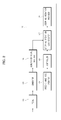
- FIG. 3 is an equivalent circuit diagram illustrating an example of the electric bicycle driving apparatus according to the first embodiment of the present invention.
- the electric bicycle driving apparatus according to the first embodiment of the present invention, denoted by reference numeral 100, is provided at one side and the other side of the electric bicycle, denoted by reference numeral 10.
- the electric bicycle driving apparatus 100 includes a speed change mode operator 101, a controller 103, a generation-signal provider 105, a stepping operation load booster 107, and a stepping operation provider 109.
- the speed change mode operator 101 is provided to output a low-speed mode signal or a high-speed mode signal.
- the speed change mode operator 101 may be provided at a portion of a handle bar of the electric bicycle 10.
- the controller 103 receives the low-speed mode signal or high-speed mode signal output from the speed change mode operator 101, and outputs a first control signal corresponding to the low-speed mode signal or a second control signal corresponding to the high-speed mode signal.
- the controller 103 may include an Electronic Controller Unit (ECU) or a Micro Controller Unit (MCU).
- ECU Electronic Controller Unit
- MCU Micro Controller Unit
- the generation-signal provider 105 is provided to provide a generation signal output from a generator 104.
- the generation-signal provider 105 may include a generation-signal rectification part 105a and a generation-signal storage part 105b.
- the generation-signal rectification part 105a may be electrically connected to the generator 104 to rectify the generation signal output from the generator 104.
- the generation-signal rectification part 105a may include more than one second rectifying diode D2 and D3, more than one fourth rectifying diode D4 and D5, and more than one sixth rectifying diode D6 and D7.
- the more than one second rectifying diode D2 and D3 may be electrically connected to one side of the generator 104, and the more than one fourth rectifying diode D4 and D5 may be electrically connected to another side of the generator 104.
- the more than one second rectifying diode D2 and D3 may include a second rectifying diode D2 and a third rectifying diode D3 connected to each other in series.
- the more than one fourth rectifying diode D4 and D5 may include a fourth rectifying diode D4 and a fifth rectifying diode D5 connected to each other in series.
- the more than one sixth rectifying diode D6 and D7 may be electrically connected to the other side of the generator 104.
- the more than one sixth rectifying diodes D6 and D7 may include a sixth rectifying diode D6 and a seventh rectifying diode D7 connected to each other in series.
- the generation-signal storage part 105b may be electrically connected to the generation-signal rectification part 1 05a to store the generation signal rectified in the generation-signal rectification part 105a.
- the generation-signal storage part 105b may include more than one second capacitor C2, C3 and C4, which is electrically connected to the generation-signal rectification part 105a and the motor-driver operating-signal regulator 107 that will be described hereinafter.
- the more than one second capacitor C2, C3 and C4 may include a second capacitor C2, a third capacitor C3, and a fourth capacitor C4 connected to one another in series.
- the more than one second capacitor C2, C3 and C4 may be a smoothing capacitor.
- the stepping operation load booster 107 is configured to boost a load of a generation signal output from the generation-signal provider 105 by receiving a first control signal or second control signal when the speed change mode operator 101 outputs a low-speed mode signal or high-speed mode signal, and to send the stepping operation provider 109 a resulting signal of the boost in a stepping operation signal corresponding to the low-speed mode signal or high-speed mode.
- the stepping operation load booster 107 may include more than one seventh resistor R7, a third switching device SW3, more than one fifth capacitor C5, more than one eighth resistor R8, and more than one sixth capacitor C6.
- the more than one seventh resistor R7 may be electrically connected to the controller 103, and the third switching device SW3 may be electrically connected to the more than one seventh resistor R7 and the stepping operation provider 109.
- the third switching device SW3 may include at least one of a Metal-Oxide Semiconductor Field Effect Transistor (MOSFET) and a Bipolar Junction Transistor (BJT).
- MOSFET Metal-Oxide Semiconductor Field Effect Transistor
- BJT Bipolar Junction Transistor
- the third switching device SW3 may include more than one zener diode ZD3 electrically connected to the stepping operation provider 109 and the more than one sixth capacitor C6 and C7 to cut off an abnormal signal from the stepping operation provider 109.
- the more than one fifth capacitor C5 may be electrically connected to the more than one seventh reisistor R7 and the third switching device SW3, and the more than one eighth resistor R8 may be electrically connected to the generation-signal provider 105.
- the more than one fifth capacitor C5 may store the first control signal or the second control signal, respectively corresponding to the low speed mode signal and the high speed mode signal that are output from the controller 103, for a predetermined time, and then provide the stored signal to the third switching device SW2 upon change to a corresponding speed mode between the low speed mode and the high speed mode.
- the more than one sixth capacitor C6 and C7 may be electrically connected to the more than one eighth resistor R8 and the third switching device SW3.
- the more than one sixth capacitor C6 and C7 may include a sixth capacitor C6 and a seventh capacitor C7 connected to each other in series.
- the more than one sixth capacitor C6 and C7 may be a smoothing capacitor.
- the stepping operation load booster 107 creates a first current-path between the more than one seventh resistor R7 and the more than one fifth capacitor C5, and a second current-path between the more than one eighth resistor R8 and the more than one sixth capacitor C6 and C7, thereby sending the stepping operation provider 109, which is to be described later, a boosted load in a stepping operation signal corresponding to the low speed mode signal or the high speed mode signal.
- the stepping operation provider 109 may receive the stepping operation signal from the stepping operation load booster 107, and output a stepping operation drive signal corresponding to the low-speed mode signal or high-speed mode signal so as to drive pedals 110 to be adapted to the high-speed mode or low-speed mode.
- the method to drive the electric bicycle 10 using the electric bicycle driving apparatus 100 includes outputting a low-speed mode signal or high-speed mode signal from the speed change mode operator 101.
- the method to drive the electric bicycle 10 using the electric bicycle driving apparatus 100 includes, at the stepping operation load booster 107, boosting a load of a generation signal output from the generation-signal provider 105 by receiving a first control signal or second control signal from the controller 103, and then sending the stepping operation provider 109 a resulting signal of the boost in a stepping operation signal corresponding to the low-speed mode signal or high-speed mode.
- the method to drive the electric bicycle 10 using the electric bicycle driving apparatus 100 includes, at the stepping operation provider 109, receiving the stepping operation signal from the stepping operation load booster 107, and outputting a stepping operation drive signal corresponding to the low-speed mode signal or high-speed mode signal so as to drive pedals 110 to be adapted to the high-speed mode or low-speed mode.
- the electric bicycle driving apparatus 100 includes the speed change mode operator 101, the controller 103, the generation-signal provider 105, the stepping operation load booster 107, and the stepping operation provider 109.
- the electric bicycle driving apparatus 100 may provide a motor driver with an optimum stepping operation by adaptively driving the pedal with a low-speed or high-speed motor driving mode in a state of the electric bicycle being stopped or in a state of the electric bicycle being running.
- FIG. 4 is a perspective view illustrating an electric bicycle including an electric bicycle driving apparatus according to a second embodiment of the present invention
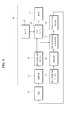
- FIG. 5 is a block diagram illustrating the configuration of the electric bicycle driving apparatus according to the second embodiment of the present invention.
- FIG. 6 is an equivalent circuit diagram illustrating an example of the electric bicycle driving apparatus according to the second embodiment of the present invention.
- an electric bicycle driving apparatus 400 according to the second embodiment of the present invention is provided at either side of the electric bicycle 10.
- the electric bicycle driving apparatus 400 includes the speed change mode operator 101, the controller 103, the generation-signal provider 105, a battery 406, the stepping operation load booster 107, the stepping operation provider 109, a motor driver 412, and a motor 414.
- the speed change mode operator 101 outputs a low-speed mode signal or high-speed mode signal.
- the speed change mode operator 101 may be installed to the handle of the electric bicycle 10.
- the controller 103 receives the low-speed mode signal or high-speed mode signal output from the speed change mode operator 101, and outputs a first control signal corresponding to the low-speed mode signal or a second control signal corresponding to the high-speed mode signal.
- the controller 103 may include an ECU or an MCU.
- the generation-signal provider 105 is for provision of a generation signal output from the generator 104.
- the generation-signal provider 105 may include the generation-signal rectification part 105a and the generation-signal storage part 105b.
- the generation-signal rectification part 105a may be electrically connected to the generator 104 to rectify the generation signal output from the generator 104.
- the generation-signal rectification part 105a may include the more than one second rectifying diode D2 and D3, more than one fourth rectifying diode D4 and D5, and more than one sixth rectifying diode D6 and D7.
- the more than one second rectifying diode D2 and D3 may be electrically connected to one side of the generator 104, and the more than one fourth rectifying diode D4 and D5 may be electrically connected to another side of the generator 104.
- the more than one second rectifying diode D2 and D3 may include the second rectifying diode D2 and third rectifying diode D3 connected to each other in series.
- the more than one fourth rectifying diode D4 and D5 may include the fourth rectifying diode D4 and fifth rectifying diode D5 connected to each other in series.
- the more than one sixth rectifying diode D6 and D7 may be electrically connected to the other side of the generator 104.
- the more than one sixth rectifying diode D6 and D7 may include the sixth rectifying diode D6 and seventh rectifying diode D7 connected to each other in series.
- the generation-signal storage part 105b may be electrically connected to the generation-signal rectification part 1 05a to store the generation signal rectified in the generation-signal rectification part 105a.
- the generation-signal storage part 105b may include more than one second capacitor C2, C3 and C4, which is electrically connected to the generation-signal rectification part 105a and the stepping operation load booster 107.
- the more than one second capacitor C2, C3 and C4 may include the second capacitor C2, third capacitor C3, and fourth capacitor C4 connected to one another in series.
- the more than one second capacitor C2, C3 and C4 may be a smoothing capacitor.
- the stepping operation load booster 107 is configured to boost a load of a generation signal output from the generation-signal provider 105 by receiving a first control signal or second control signal when the speed change mode operator 101 outputs a low-speed mode signal or high-speed mode signal, and to send the stepping operation provider 109, which is to be described later, the boosted load in a stepping operation signal corresponding to the low-speed mode signal or high-speed mode.
- the stepping operation load booster 107 may include more than one seventh resistor R7, a third switching device SW3, more than one fifth capacitor C5, more than one eighth resistor R8, and more than one sixth capacitor C6.
- the more than one seventh resistor R7 may be electrically connected to the controller 103, and the third switching device SW3 may be electrically connected to the more than one seventh resistor R7 and the stepping operation provider 109.
- the third switching device SW3 may include at least one of a Metal-Oxide Semiconductor Field Effect Transistor (MOSFET) and a Bipolar Junction Transistor (BJT).
- MOSFET Metal-Oxide Semiconductor Field Effect Transistor
- BJT Bipolar Junction Transistor
- the third switching device SW3 may include more than one zener diode ZD3 electrically connected to the stepping operation provider 109 and the more than one sixth capacitor C6 and C7 to cut off an abnormal signal from the stepping operation provider 109.
- the more than one fifth capacitor C5 may be electrically connected to the more than one seventh reisistor R7 and the third switching device SW3, and the more than one eighth resistor R8 may be electrically connected to the generation-signal provider 105.
- the more than one fifth capacitor C5 may store the first control signal or the second control signal, respectively corresponding to the low speed mode signal and the high speed mode signal that are output from the controller 103, for a predetermined time, and then provide the stored signal to the third switching device SW2 upon change to a corresponding speed mode between the low speed mode and the high speed mode.
- the more than one sixth capacitor C6 and C7 may be electrically connected to the more than one eighth resistor R8 and the third switching device SW3.
- the more than one sixth capacitor C6 and C7 may include a sixth capacitor C6 and a seventh capacitor C7 connected to each other in series.
- the more than one sixth capacitor C6 and C7 may be a smoothing capacitor.
- the stepping operation load booster 107 creates a first current-path between the more than one seventh resistor R7 and the more than one fifth capacitor C5, and a second current-path between the more than one eighth resistor R8 and the more than one sixth capacitor C6 and C7, thereby sending the stepping operation provider 109, which is to be described later, a boosted load in a stepping operation signal corresponding to the low speed mode signal or the high speed mode signal.
- the stepping operation provider 109 may receive the stepping operation signal from the stepping operation load booster 107, and output a stepping operation drive signal corresponding to the low-speed mode signal or high-speed mode signal so as to drive pedals 110 to be adapted to the high-speed mode or low-speed mode.
- the motor driver 412 may be electrically connected to the generation-signal provider 105 to receive the generation signal from the generation-signal provider 105 and to receive power of a battery, thereby driving the motor 414.
- the motor driver 412 may be a three-phase motor driver.
- the motor driver 412 may include a motor-driver operating signal regulating circuit 412a and a motor drive circuit 412b.
- the motor-driver operating signal regulating circuit 412a may include the first switching device SW1, more than one first resistor R1 and R2, more than one fourth resistance R4, R5 and R6, and second switching device SW2.
- the first switching device SW1 may be electrically connected to one side of the controller 103, and the more than one first resistor R1 and R2 may be electrically connected to the other side of the controller 103 and the first switching device SW1.
- the more than one first resistor R1 and R2 may include the first resistor R1 and second resistor R2 for dividing voltage.
- the first switching device SW1 may include at least one of an MOSFET and a BJT.
- the more than one fourth resistor R4, R5 and R6 may be electrically connected to the first switching device SW1
- the second switching device SW2 may be electrically connected to the generation-signal provider 105 and the more than one fourth resistor R4, R5 and R6.
- the more than one fourth resistor R4, R5 and R6 may include a fourth resistor R4, a fifth resistor R5, and a sixth resistor R6 for dividing voltage.
- the second switching device SW2 may include at least one of a Metal-Oxide Semiconductor Field Effect Transistor (MOSFET) and a Bipolar Junction Transistor (BJT).
- MOSFET Metal-Oxide Semiconductor Field Effect Transistor
- BJT Bipolar Junction Transistor
- the second switching device SW2 may include more than one zener diode ZD2 electrically connected to the generation-signal provider 105 and the more than one fourth resistor R4, R5 and R6 to cut off an abnormal signal from the first switching device SW1.
- the motor-driver operating signal regulating circuit 412a may include more than one zener diode ZD1 electrically connected to the generation signal provider 105 and the more than one fourth resistor R4, R5 and R6 to cut off an abnormal signal from the first switching device SW1..
- the more than one zener diode ZD1 is electrically connected to the generation-signal provider 105 and one resistor R6 among the more than one fourth resistor R4, R5 and R6 to cut off an abnormal signal transmitted from the first switching device SW1.
- the motor-driver operating signal regulating circuit 412a creates a first current-path among the more than one fourth resistor R4, R5 and R6.
- the motor-driver operating-signal regulating circuit 412a receives a first control signal or second control signal from the controller 103, turning on the first switching device SW1.
- the motor-driver operating-signal regulating circuit 412a also creates a second current-path among the more than one fourth resistor R4, R5 and R6 to thereby turn on the second switching device SW2.
- the motor-driver operating-signal regulating circuit 412a may regulate the level of generation signal from the generation-signal provider 105 via the more than one fourth resistor R4, R5 and R6, so as to lower the level of generation signal to be transmitted to the motor drive circuit 412b that is operated upon receiving power of the battery 406.
- the more than one capacitor C1 may be electrically connected to the second switching device SW2, the first switching device SW1 and battery 406.
- the more than one capacitor C1 may be a smoothing capacitor.
- the more than one capacitor C1 may temporarily store the regulated generation signal, and then provide the signal to the motor 414 at an operating time of the motor drive circuit412b.
- the more than one capacitor C1 may remove a noise signal from the regulated generation signal, and provide the resulting signal to the motor 414.
- the more than one rectifying diode D1 may be electrically connected to the second switching device SW2, more than one capacitor C1 and battery 406, to rectify power output from the battery 406 and apply the power to the motor drive circuit 412b.
- the method to drive the electric bicycle 10 using the electric bicycle driving apparatus 400 according to the second embodiment of the present invention includes outputting a low-speed mode signal or high-speed mode signal from the speed change mode operator 101.
- the method to drive the electric bicycle 10 using the electric bicycle driving apparatus 400 includes, at the stepping operation load booster 107, boosting a load of a generation signal output from the generation-signal provider 105 by receiving a first control signal or second control signal from the controller 103, and then sending the stepping operation provider 109 a resulting signal of the boost in a stepping operation signal corresponding to the low-speed mode signal or high-speed mode.
- the method to drive the electric bicycle 10 using the electric bicycle driving apparatus 400 includes, at the stepping operation provider 109, receiving the stepping operation signal from the stepping operation load booster 107, and outputting a stepping operation drive signal corresponding to the low-speed mode signal or high-speed mode signal so as to drive pedals 110 to be adapted to the high-speed mode or low-speed mode.
- the method to drive the electric bicycle 10 using the electric bicycle driving apparatus 400 according to the second embodiment of the present invention includes outputting a low-speed mode signal or high-speed mode signal from the speed change mode operator 101..
- the method to drive the electric bicycle 10 using the electric bicycle driving apparatus 400 includes, at the motor driver 412, receiving a generation signal from the generation signal provider 105 and receiving power of the battery 406, thereby driving the motor 414.
- the method to drive the electric bicycle 10 using the electric bicycle driving apparatus 400 includes, at the stepping operation load booster 107, boosting a load of a generation signal output from the generation-signal provider 105 by receiving a first control signal or second control signal from the controller 103, and then sending the stepping operation provider 109 a resulting signal of the boost in a stepping operation signal corresponding to the low-speed mode signal or high-speed mode.
- the method to drive the electric bicycle 10 using the electric bicycle driving apparatus 400 includes, at the stepping operation provider 109, receiving the stepping operation signal from the stepping operation load booster 107, and outputting a stepping operation drive signal corresponding to the low-speed mode signal or high-speed mode signal so as to drive pedals 110 to be adapted to the high-speed mode or low-speed mode.
- the electric bicycle driving apparatus 400 includes the speed change mode operation 101, the controller 103, the generation signal provider 105, the stepping operation load booster 107, the stepping operation provider 109, the motor driver 412 and the motor 414.
- the electric bicycle driving apparatus 400 can provide a motor driver with an optimum stepping operation by adaptively driving the pedal with a low-speed or high-speed motor driving mode in a state of the electric bicycle being stopped or in a state of the electric bicycle being running.
Landscapes
- Engineering & Computer Science (AREA)
- Transportation (AREA)
- Mechanical Engineering (AREA)
- Power Engineering (AREA)
- Chemical & Material Sciences (AREA)
- Combustion & Propulsion (AREA)
- Electric Propulsion And Braking For Vehicles (AREA)
Abstract
Description
- This application claims the benefit of Korean Patent Application No.
2012-0104169, filed on September 19, 2012 - Embodiments of the present invention relate to an electric bicycle driving apparatus.
- In general, electric bicycle driving apparatuses are provided to drive electric bicycles.
- Most conventional driving apparatuses for electric bicycles, in driving a motor of the electric bicycle in a low-speed or high-speed motor driving mode, have a limit to adaptation ofa stepping operation of a pedal to a low-speed or high-speed motor driving mode
- Accordingly, numerous researches have been conducted on the electric bicycle capable of providing a motor driver with an optimum stepping operation by adaptively driving the pedal with a low-speed or high-speed motor driving mode in a state of the electric bicycle being stopped or in a state of the electric bicycle being running.
- Therefore, it is an aspect of the present invention to provide an electric bicycle capable of providing a motor driver with an optimum stepping operation by adaptively driving the pedal with a low-speed or high-speed motor driving mode in a state of the electric bicycle being stopped or in a state of the electric bicycle being running
- Additional aspects of the invention will be set forth in part in the description which follows and, in part, will be obvious from the description, or may be learned by practice of the invention.
- In accordance with one aspect of the present invention, an electric bicycle driving apparatus includes a speed change mode operator, a controller, a generation-signal provider, a stepping operation load booster, and a stepping operation provider. The speed change mode operator may be configured to output a low-speed mode signal or a high-speed mode signal. The controller may be configured to receive the low-speed mode signal or high-speed mode signal output from the speed change mode operator and to output a first control signal corresponding to the low-speed mode signal or a second control signal corresponding to the high-speed mode signal. The generation-signal provider may be configured to provide a generation signal output from a generator. The stepping operation load booster may be configured to boost a load of the generation signal output from the generation-signal provider by receiving the first control signal or second control signal when the speed change mode operator outputs the low-speed mode signal or high-speed mode signal, and to send a stepping operation provider a resulting signal of the boost in a stepping operation signal corresponding to the low-speed mode signal or high-speed mode. The stepping operation provider may be configured to receive the stepping operation signal from the stepping operation load booster, and to output a stepping operation drive signal corresponding to the low-speed mode signal or high-speed mode signal so as to drive pedals to be adapted to the high-speed mode or low-speed mode.
- These and/or other aspects of the invention will become apparent and more readily appreciated from the following description of the embodiments, taken in conjunction with the accompanying drawings of which:
-
FIG. 1 is a perspective view illustrating an electric bicycle including an electric bicycle driving apparatus according to a first embodiment of the present invention; -
FIG. 2 is a block diagram illustrating a configuration of the electric bicycle driving apparatus according to the first embodiment of the present invention; -
FIG. 3 is an equivalent circuit diagram illustrating an example of the electric bicycle driving apparatus according to the first embodiment of the present invention; -
FIG. 4 is a perspective view illustrating an electric bicycle including an electric bicycle driving apparatus according to a second embodiment of the present invention; -
FIG. 5 is a block diagram illustrating the configuration of the electric bicycle driving apparatus according to the second embodiment of the present invention; and -
FIG. 6 is an equivalent circuit diagram of another example of the electric bicycle driving apparatus according to the second embodiment of the present invention. - Reference will now be made in detail to the embodiments of the present invention, examples of which are illustrated in the accompanying drawings, wherein like reference numerals refer to like elements throughout.
-
FIG. 1 is a perspective view illustrating an electric bicycle including an electric bicycle driving apparatus according to a first embodiment of the present invention, andFIG. 2 is a block diagram illustrating the configuration of the electric bicycle driving apparatus according to the first embodiment of the present invention. -
FIG. 3 is an equivalent circuit diagram illustrating an example of the electric bicycle driving apparatus according to the first embodiment of the present invention. - First, referring to
FIG. 1 , the electric bicycle driving apparatus according to the first embodiment of the present invention, denoted byreference numeral 100, is provided at one side and the other side of the electric bicycle, denoted byreference numeral 10. - Next, referring to
FIGS. 2 and3 , the electricbicycle driving apparatus 100 according to the first embodiment of the present invention includes a speedchange mode operator 101, acontroller 103, a generation-signal provider 105, a steppingoperation load booster 107, and astepping operation provider 109. - The speed
change mode operator 101 is provided to output a low-speed mode signal or a high-speed mode signal. - The speed
change mode operator 101 may be provided at a portion of a handle bar of theelectric bicycle 10. - The
controller 103 receives the low-speed mode signal or high-speed mode signal output from the speedchange mode operator 101, and outputs a first control signal corresponding to the low-speed mode signal or a second control signal corresponding to the high-speed mode signal. - The
controller 103 may include an Electronic Controller Unit (ECU) or a Micro Controller Unit (MCU). - The generation-
signal provider 105 is provided to provide a generation signal output from agenerator 104. - The generation-
signal provider 105 may include a generation-signal rectification part 105a and a generation-signal storage part 105b. - The generation-
signal rectification part 105a may be electrically connected to thegenerator 104 to rectify the generation signal output from thegenerator 104. - The generation-
signal rectification part 105a may include more than one second rectifying diode D2 and D3, more than one fourth rectifying diode D4 and D5, and more than one sixth rectifying diode D6 and D7. - The more than one second rectifying diode D2 and D3 may be electrically connected to one side of the
generator 104, and the more than one fourth rectifying diode D4 and D5 may be electrically connected to another side of thegenerator 104. - The more than one second rectifying diode D2 and D3 may include a second rectifying diode D2 and a third rectifying diode D3 connected to each other in series.
- The more than one fourth rectifying diode D4 and D5 may include a fourth rectifying diode D4 and a fifth rectifying diode D5 connected to each other in series.
- The more than one sixth rectifying diode D6 and D7 may be electrically connected to the other side of the
generator 104. - The more than one sixth rectifying diodes D6 and D7 may include a sixth rectifying diode D6 and a seventh rectifying diode D7 connected to each other in series.
- The generation-
signal storage part 105b may be electrically connected to the generation-signal rectification part 1 05a to store the generation signal rectified in the generation-signal rectification part 105a. - The generation-
signal storage part 105b may include more than one second capacitor C2, C3 and C4, which is electrically connected to the generation-signal rectification part 105a and the motor-driver operating-signal regulator 107 that will be described hereinafter. - The more than one second capacitor C2, C3 and C4 may include a second capacitor C2, a third capacitor C3, and a fourth capacitor C4 connected to one another in series.
- The more than one second capacitor C2, C3 and C4 may be a smoothing capacitor.
- The stepping
operation load booster 107 is configured to boost a load of a generation signal output from the generation-signal provider 105 by receiving a first control signal or second control signal when the speedchange mode operator 101 outputs a low-speed mode signal or high-speed mode signal, and to send the stepping operation provider 109 a resulting signal of the boost in a stepping operation signal corresponding to the low-speed mode signal or high-speed mode. - Specifically, the stepping
operation load booster 107 may include more than one seventh resistor R7, a third switching device SW3, more than one fifth capacitor C5, more than one eighth resistor R8, and more than one sixth capacitor C6. - The more than one seventh resistor R7 may be electrically connected to the
controller 103, and the third switching device SW3 may be electrically connected to the more than one seventh resistor R7 and thestepping operation provider 109. - The third switching device SW3 may include at least one of a Metal-Oxide Semiconductor Field Effect Transistor (MOSFET) and a Bipolar Junction Transistor (BJT).
- The third switching device SW3 may include more than one zener diode ZD3 electrically connected to the
stepping operation provider 109 and the more than one sixth capacitor C6 and C7 to cut off an abnormal signal from thestepping operation provider 109. - The more than one fifth capacitor C5 may be electrically connected to the more than one seventh reisistor R7 and the third switching device SW3, and the more than one eighth resistor R8 may be electrically connected to the generation-
signal provider 105. - The more than one fifth capacitor C5 may store the first control signal or the second control signal, respectively corresponding to the low speed mode signal and the high speed mode signal that are output from the
controller 103, for a predetermined time, and then provide the stored signal to the third switching device SW2 upon change to a corresponding speed mode between the low speed mode and the high speed mode. - The more than one sixth capacitor C6 and C7 may be electrically connected to the more than one eighth resistor R8 and the third switching device SW3.
- The more than one sixth capacitor C6 and C7 may include a sixth capacitor C6 and a seventh capacitor C7 connected to each other in series.
- The more than one sixth capacitor C6 and C7 may be a smoothing capacitor.
- The stepping
operation load booster 107 creates a first current-path between the more than one seventh resistor R7 and the more than one fifth capacitor C5, and a second current-path between the more than one eighth resistor R8 and the more than one sixth capacitor C6 and C7, thereby sending thestepping operation provider 109, which is to be described later, a boosted load in a stepping operation signal corresponding to the low speed mode signal or the high speed mode signal. - The
stepping operation provider 109 may receive the stepping operation signal from the steppingoperation load booster 107, and output a stepping operation drive signal corresponding to the low-speed mode signal or high-speed mode signal so as to drivepedals 110 to be adapted to the high-speed mode or low-speed mode. - Hereinafter, a method to drive the
electric bicycle 10 using the electricbicycle driving apparatus 100 according to the first embodiment of the present invention will be described. - First, the method to drive the
electric bicycle 10 using the electricbicycle driving apparatus 100 according to the first embodiment of the present invention includes outputting a low-speed mode signal or high-speed mode signal from the speedchange mode operator 101. - Thereafter, the method to drive the
electric bicycle 10 using the electricbicycle driving apparatus 100 according to the first embodiment of the present invention includes, at the steppingoperation load booster 107, boosting a load of a generation signal output from the generation-signal provider 105 by receiving a first control signal or second control signal from thecontroller 103, and then sending the stepping operation provider 109 a resulting signal of the boost in a stepping operation signal corresponding to the low-speed mode signal or high-speed mode. - Finally, the method to drive the
electric bicycle 10 using the electricbicycle driving apparatus 100 according to the first embodiment of the present invention includes, at the steppingoperation provider 109, receiving the stepping operation signal from the steppingoperation load booster 107, and outputting a stepping operation drive signal corresponding to the low-speed mode signal or high-speed mode signal so as to drivepedals 110 to be adapted to the high-speed mode or low-speed mode. - The electric
bicycle driving apparatus 100 according to the first embodiment of the present invention includes the speedchange mode operator 101, thecontroller 103, the generation-signal provider 105, the steppingoperation load booster 107, and the steppingoperation provider 109. - Accordingly, the electric
bicycle driving apparatus 100 according to the first embodiment of the present invention may provide a motor driver with an optimum stepping operation by adaptively driving the pedal with a low-speed or high-speed motor driving mode in a state of the electric bicycle being stopped or in a state of the electric bicycle being running. -
FIG. 4 is a perspective view illustrating an electric bicycle including an electric bicycle driving apparatus according to a second embodiment of the present invention, andFIG. 5 is a block diagram illustrating the configuration of the electric bicycle driving apparatus according to the second embodiment of the present invention. -
FIG. 6 is an equivalent circuit diagram illustrating an example of the electric bicycle driving apparatus according to the second embodiment of the present invention. - Referring to
FIG. 4 , an electricbicycle driving apparatus 400 according to the second embodiment of the present invention is provided at either side of theelectric bicycle 10. - Referring to
FIGS. 5 and6 , the electricbicycle driving apparatus 400 according to the second embodiment of the present invention includes the speedchange mode operator 101, thecontroller 103, the generation-signal provider 105, abattery 406, the steppingoperation load booster 107, the steppingoperation provider 109, amotor driver 412, and amotor 414. - The speed
change mode operator 101 outputs a low-speed mode signal or high-speed mode signal. - The speed
change mode operator 101 may be installed to the handle of theelectric bicycle 10. - The
controller 103 receives the low-speed mode signal or high-speed mode signal output from the speedchange mode operator 101, and outputs a first control signal corresponding to the low-speed mode signal or a second control signal corresponding to the high-speed mode signal. - The
controller 103 may include an ECU or an MCU. - The generation-
signal provider 105 is for provision of a generation signal output from thegenerator 104. - The generation-
signal provider 105 may include the generation-signal rectification part 105a and the generation-signal storage part 105b. - The generation-
signal rectification part 105a may be electrically connected to thegenerator 104 to rectify the generation signal output from thegenerator 104. - The generation-
signal rectification part 105a may include the more than one second rectifying diode D2 and D3, more than one fourth rectifying diode D4 and D5, and more than one sixth rectifying diode D6 and D7. - The more than one second rectifying diode D2 and D3 may be electrically connected to one side of the
generator 104, and the more than one fourth rectifying diode D4 and D5 may be electrically connected to another side of thegenerator 104. - The more than one second rectifying diode D2 and D3 may include the second rectifying diode D2 and third rectifying diode D3 connected to each other in series.
- The more than one fourth rectifying diode D4 and D5 may include the fourth rectifying diode D4 and fifth rectifying diode D5 connected to each other in series.
- The more than one sixth rectifying diode D6 and D7 may be electrically connected to the other side of the
generator 104. - The more than one sixth rectifying diode D6 and D7 may include the sixth rectifying diode D6 and seventh rectifying diode D7 connected to each other in series.
- The generation-
signal storage part 105b may be electrically connected to the generation-signal rectification part 1 05a to store the generation signal rectified in the generation-signal rectification part 105a. - The generation-
signal storage part 105b may include more than one second capacitor C2, C3 and C4, which is electrically connected to the generation-signal rectification part 105a and the steppingoperation load booster 107. - The more than one second capacitor C2, C3 and C4 may include the second capacitor C2, third capacitor C3, and fourth capacitor C4 connected to one another in series.
- The more than one second capacitor C2, C3 and C4 may be a smoothing capacitor.
- The stepping
operation load booster 107 is configured to boost a load of a generation signal output from the generation-signal provider 105 by receiving a first control signal or second control signal when the speedchange mode operator 101 outputs a low-speed mode signal or high-speed mode signal, and to send the steppingoperation provider 109, which is to be described later, the boosted load in a stepping operation signal corresponding to the low-speed mode signal or high-speed mode. - Specifically, the stepping
operation load booster 107 may include more than one seventh resistor R7, a third switching device SW3, more than one fifth capacitor C5, more than one eighth resistor R8, and more than one sixth capacitor C6. - The more than one seventh resistor R7 may be electrically connected to the
controller 103, and the third switching device SW3 may be electrically connected to the more than one seventh resistor R7 and the steppingoperation provider 109. - The third switching device SW3 may include at least one of a Metal-Oxide Semiconductor Field Effect Transistor (MOSFET) and a Bipolar Junction Transistor (BJT).
- The third switching device SW3 may include more than one zener diode ZD3 electrically connected to the stepping
operation provider 109 and the more than one sixth capacitor C6 and C7 to cut off an abnormal signal from the steppingoperation provider 109. - The more than one fifth capacitor C5 may be electrically connected to the more than one seventh reisistor R7 and the third switching device SW3, and the more than one eighth resistor R8 may be electrically connected to the generation-
signal provider 105. - The more than one fifth capacitor C5 may store the first control signal or the second control signal, respectively corresponding to the low speed mode signal and the high speed mode signal that are output from the
controller 103, for a predetermined time, and then provide the stored signal to the third switching device SW2 upon change to a corresponding speed mode between the low speed mode and the high speed mode. - The more than one sixth capacitor C6 and C7 may be electrically connected to the more than one eighth resistor R8 and the third switching device SW3.
- The more than one sixth capacitor C6 and C7 may include a sixth capacitor C6 and a seventh capacitor C7 connected to each other in series.
- The more than one sixth capacitor C6 and C7 may be a smoothing capacitor.
- The stepping
operation load booster 107 creates a first current-path between the more than one seventh resistor R7 and the more than one fifth capacitor C5, and a second current-path between the more than one eighth resistor R8 and the more than one sixth capacitor C6 and C7, thereby sending the steppingoperation provider 109, which is to be described later, a boosted load in a stepping operation signal corresponding to the low speed mode signal or the high speed mode signal. - The stepping
operation provider 109 may receive the stepping operation signal from the steppingoperation load booster 107, and output a stepping operation drive signal corresponding to the low-speed mode signal or high-speed mode signal so as to drivepedals 110 to be adapted to the high-speed mode or low-speed mode. - The
motor driver 412 may be electrically connected to the generation-signal provider 105 to receive the generation signal from the generation-signal provider 105 and to receive power of a battery, thereby driving themotor 414. - The
motor driver 412 may be a three-phase motor driver. - Specifically, the
motor driver 412 may include a motor-driver operatingsignal regulating circuit 412a and amotor drive circuit 412b. - The motor-driver operating
signal regulating circuit 412a may include the first switching device SW1, more than one first resistor R1 and R2, more than one fourth resistance R4, R5 and R6, and second switching device SW2. - The first switching device SW1 may be electrically connected to one side of the
controller 103, and the more than one first resistor R1 and R2 may be electrically connected to the other side of thecontroller 103 and the first switching device SW1. - The more than one first resistor R1 and R2 may include the first resistor R1 and second resistor R2 for dividing voltage.
- The first switching device SW1 may include at least one of an MOSFET and a BJT.The more than one fourth resistor R4, R5 and R6 may be electrically connected to the first switching device SW1, and the second switching device SW2 may be electrically connected to the generation-
signal provider 105 and the more than one fourth resistor R4, R5 and R6. - The more than one fourth resistor R4, R5 and R6 may include a fourth resistor R4, a fifth resistor R5, and a sixth resistor R6 for dividing voltage.
- The second switching device SW2 may include at least one of a Metal-Oxide Semiconductor Field Effect Transistor (MOSFET) and a Bipolar Junction Transistor (BJT).
- The second switching device SW2 may include more than one zener diode ZD2 electrically connected to the generation-
signal provider 105 and the more than one fourth resistor R4, R5 and R6 to cut off an abnormal signal from the first switching device SW1. - The motor-driver operating
signal regulating circuit 412a may include more than one zener diode ZD1 electrically connected to thegeneration signal provider 105 and the more than one fourth resistor R4, R5 and R6 to cut off an abnormal signal from the first switching device SW1.. - That is, the more than one zener diode ZD1 is electrically connected to the generation-
signal provider 105 and one resistor R6 among the more than one fourth resistor R4, R5 and R6 to cut off an abnormal signal transmitted from the first switching device SW1. - The motor-driver operating
signal regulating circuit 412a creates a first current-path among the more than one fourth resistor R4, R5 and R6. When the speedchange mode operator 105 outputs a low-speed mode signal or high-speed mode signal, the motor-driver operating-signal regulating circuit 412a receives a first control signal or second control signal from thecontroller 103, turning on the first switching device SW1. The motor-driver operating-signal regulating circuit 412a also creates a second current-path among the more than one fourth resistor R4, R5 and R6 to thereby turn on the second switching device SW2. As such, the motor-driver operating-signal regulating circuit 412a may regulate the level of generation signal from the generation-signal provider 105 via the more than one fourth resistor R4, R5 and R6, so as to lower the level of generation signal to be transmitted to themotor drive circuit 412b that is operated upon receiving power of thebattery 406. - The more than one capacitor C1 may be electrically connected to the second switching device SW2, the first switching device SW1 and
battery 406. - The more than one capacitor C1 may be a smoothing capacitor.
- The more than one capacitor C1 may temporarily store the regulated generation signal, and then provide the signal to the
motor 414 at an operating time of the motor drive circuit412b. - The more than one capacitor C1 may remove a noise signal from the regulated generation signal, and provide the resulting signal to the
motor 414. - The more than one rectifying diode D1 may be electrically connected to the second switching device SW2, more than one capacitor C1 and
battery 406, to rectify power output from thebattery 406 and apply the power to themotor drive circuit 412b. - Hereinafter, a method to drive the
electric bicycle 10 using the electricbicycle driving apparatus 400 according to the second embodiment of the present invention will be described. - First, the method to drive the
electric bicycle 10 using the electricbicycle driving apparatus 400 according to the second embodiment of the present invention includes outputting a low-speed mode signal or high-speed mode signal from the speedchange mode operator 101. - Thereafter, the method to drive the
electric bicycle 10 using the electricbicycle driving apparatus 400 according to the second embodiment of the present invention includes, at the steppingoperation load booster 107, boosting a load of a generation signal output from the generation-signal provider 105 by receiving a first control signal or second control signal from thecontroller 103, and then sending the stepping operation provider 109 a resulting signal of the boost in a stepping operation signal corresponding to the low-speed mode signal or high-speed mode. - Finally, the method to drive the
electric bicycle 10 using the electricbicycle driving apparatus 400 according to the second embodiment of the present invention includes, at the steppingoperation provider 109, receiving the stepping operation signal from the steppingoperation load booster 107, and outputting a stepping operation drive signal corresponding to the low-speed mode signal or high-speed mode signal so as to drivepedals 110 to be adapted to the high-speed mode or low-speed mode. - Meanwhile, another example of a method to drive the
electric bicycle 10 using the electricbicycle driving apparatus 400 according to the second embodiment of the present invention will be described. - First, the method to drive the
electric bicycle 10 using the electricbicycle driving apparatus 400 according to the second embodiment of the present invention includes outputting a low-speed mode signal or high-speed mode signal from the speedchange mode operator 101.. - Thereafter, the method to drive the
electric bicycle 10 using the electricbicycle driving apparatus 400 according to the second embodiment of the present invention includes, at themotor driver 412, receiving a generation signal from thegeneration signal provider 105 and receiving power of thebattery 406, thereby driving themotor 414. - Thereafter, the method to drive the
electric bicycle 10 using the electricbicycle driving apparatus 400 according to the second embodiment of the present invention includes, at the steppingoperation load booster 107, boosting a load of a generation signal output from the generation-signal provider 105 by receiving a first control signal or second control signal from thecontroller 103, and then sending the stepping operation provider 109 a resulting signal of the boost in a stepping operation signal corresponding to the low-speed mode signal or high-speed mode. - Finally, the method to drive the
electric bicycle 10 using the electricbicycle driving apparatus 400 according to the second embodiment of the present invention includes, at the steppingoperation provider 109, receiving the stepping operation signal from the steppingoperation load booster 107, and outputting a stepping operation drive signal corresponding to the low-speed mode signal or high-speed mode signal so as to drivepedals 110 to be adapted to the high-speed mode or low-speed mode. - The electric
bicycle driving apparatus 400 according to the second embodiment of the present invention includes the speedchange mode operation 101, thecontroller 103, thegeneration signal provider 105, the steppingoperation load booster 107, the steppingoperation provider 109, themotor driver 412 and themotor 414. - Accordingly, the electric
bicycle driving apparatus 400 according to the second embodiment of the present invention can provide a motor driver with an optimum stepping operation by adaptively driving the pedal with a low-speed or high-speed motor driving mode in a state of the electric bicycle being stopped or in a state of the electric bicycle being running. - Although a few embodiments of the present invention have been shown and described, it would be appreciated by those skilled in the art that changes may be made in these embodiments without departing from the principles and spirit of the invention, the scope of which is defined in the claims and their equivalents.
Claims (15)
- An electric bicycle driving apparatus comprising:a speed change mode operator to output a low-speed mode signal or a high-speed mode signal;a controller to receive the low-speed mode signal or high-speed mode signal output from the speed change mode operator and to output a first control signal corresponding to the low-speed mode signal or a second control signal corresponding to the high-speed mode signal;a generation-signal provider to provide a generation signal output from a generator;a stepping operation load booster to boost a load of the generation signal output from the generation-signal provider by receiving the first control signal or second control signal when the speed change mode operator outputs the low-speed mode signal or high-speed mode signal, and to send a stepping operation provider a resulting signal of the boost in a stepping operation signal corresponding to the low-speed mode signal or high-speed mode; andthe stepping operation provider to receive the stepping operation signal from the stepping operation load booster, and to output a stepping operation drive signal corresponding to the low-speed mode signal or high-speed mode signal so as to drive pedals to be adapted to the high-speed mode or low-speed mode.
- The apparatus according to claim 1, wherein the stepping operation load booster includes:more than one seventh resistor electrically connected to the controller;a third switching device electrically connected to the more than one seventh resistor and the stepping operation provider;more than one fifth capacitor electrically connected to the more than one seventh resistor and the third switching device;more than one eighth resistor electrically connected to the generation-signal provider; andmore than one sixth capacitor electrically connected to the more than one eighth resistor and the third switching device.
- The apparatus according to claim 2, wherein the more than one sixth capacitor includes a sixth capacitor and a seventh capacitor connected to each other in series.
- The apparatus according to claim 1, wherein the generation-signal provider includes:a generation-signal rectification part electrically connected to the generator to rectify the generation signal output from the generator; anda generation-signal storage part electrically connected to the generation-signal rectification part to store the generation signal rectified in the generation-signal rectification part.
- The apparatus according to claim 4, wherein the generation-signal rectification part includes:more than one second rectifying diode electrically connected to one side of the generator;more than one fourth rectifying diode electrically connected to another side of the generator; andmore than one sixth rectifying diode electrically connected to the other side of the generator.
- The apparatus according to claim 5, wherein the more than one second rectifying diode includes a second rectifying diode and a third rectifying diode connected to each other in series.
- The apparatus according to claim 5, wherein the more than one fourth rectifying diode includes a fourth rectifying diode and a fifth rectifying diode connected to each other in series.
- The apparatus according to claim 5, wherein the more than one sixth rectifying diode includes a sixth rectifying diode and a seventh rectifying diode connected to each other in series.
- The apparatus according to claim 4, wherein the generation-signal storage part includes more than one second capacitor electrically connected to the generation-signal rectification part and the stepping operation load booster
- The apparatus according to claim 9, wherein the more than one second capacitor includes a second capacitor, a third capacitor and a fourth capacitor connected to one another in series.
- The apparatus according to claim 1, further comprising a motor driver electrically connected to the generation-signal provider to receive the generation signal from the generation-signal provider and to receive power of a battery, thereby driving a motor,
wherein the motor driver includes a motor-driver operating signal regulating circuit and a motor drive circuit,
wherein the motor-driver operating signal regulating circuit includes:a first switching device electrically connected to one side of the controller;more than one first resistor electrically connected to another side of the controller and the first switching device;more than one fourth resistor electrically connected to the first switching device; anda second switching device electrically connected to the generation-signal provider and the more than one fourth resistor. - The apparatus according to claim 11, wherein the more than one first resistor includes a first resistor and a second resistor for dividing voltage.
- The apparatus according to claim 11, wherein the more than one fourth resistor includes a fourth resistor, a fifth resistor, and a sixth resistor for dividing voltage.
- The apparatus according to claim 11, wherein further comprising more than one capacitor electrically connected to the second switching device, the first switching device and the battery.
- The apparatus according to claim 14, further comprising more than one rectifying diode electrically connected to the second switching device, the more than one capacitor and the battery.
Applications Claiming Priority (1)
| Application Number | Priority Date | Filing Date | Title |
|---|---|---|---|
| KR1020120104169A KR101366557B1 (en) | 2012-09-19 | 2012-09-19 | Apparatus for driving electric bicycle |
Publications (2)
| Publication Number | Publication Date |
|---|---|
| EP2711238A2 true EP2711238A2 (en) | 2014-03-26 |
| EP2711238A3 EP2711238A3 (en) | 2017-10-11 |
Family
ID=47191525
Family Applications (1)
| Application Number | Title | Priority Date | Filing Date |
|---|---|---|---|
| EP12190210.0A Withdrawn EP2711238A3 (en) | 2012-09-19 | 2012-10-26 | Electric bicycle driving apparatus |
Country Status (4)
| Country | Link |
|---|---|
| US (1) | US9002555B2 (en) |
| EP (1) | EP2711238A3 (en) |
| KR (1) | KR101366557B1 (en) |
| CN (1) | CN103661766B (en) |
Families Citing this family (7)
| Publication number | Priority date | Publication date | Assignee | Title |
|---|---|---|---|---|
| DE102013216723A1 (en) * | 2013-08-22 | 2015-02-26 | Robert Bosch Gmbh | Muscle and / or engine power operable vehicle and method of operating the vehicle |
| KR101830239B1 (en) * | 2016-04-26 | 2018-02-21 | 주식회사 만도 | Pedal feeling adjust apparatus of pedal generator in electric bicycle and pedal feeling adjust method thereof |
| JP6679459B2 (en) * | 2016-10-05 | 2020-04-15 | 株式会社シマノ | Bicycle power supply device and bicycle electric device including the same |
| KR102676489B1 (en) * | 2021-10-21 | 2024-06-19 | 에이치엘만도 주식회사 | Driving apparatus for electric bicycle and controlling method of electric bicycle |
| US20230373590A1 (en) * | 2022-05-19 | 2023-11-23 | Hl Mando Corporation | Apparatus and method for driving electric bicycle |
| ES2960111A1 (en) * | 2022-08-01 | 2024-02-29 | Bh Bikes Europe S L | MOTORIZED ASSIST CONTROL SYSTEM FOR ELECTRIC BICYCLES AND ELECTRIC BICYCLES THAT INCORPORATE SUCH SYSTEM |
| KR102951861B1 (en) | 2024-01-26 | 2026-04-13 | 에이치엘만도 주식회사 | Method and system for controlling motor of electric bicycle |
Family Cites Families (65)
| Publication number | Priority date | Publication date | Assignee | Title |
|---|---|---|---|---|
| US3921745A (en) * | 1973-07-23 | 1975-11-25 | Mcculloch Corp | Electric bicycle |
| US4523193A (en) * | 1983-11-21 | 1985-06-11 | Levinson Samuel H | Remote-controlled doorbell signal receiver |
| DE69231799T2 (en) * | 1991-06-04 | 2001-08-09 | Yamaha Hatsudoki K.K., Iwata | Muscle-powered vehicle |
| US5237263A (en) * | 1991-06-17 | 1993-08-17 | Gannon Henry M | Electric and pedal driven bicycle with solar charging |
| US5491390A (en) * | 1994-01-18 | 1996-02-13 | Mcgreen; James R. | Electric propulsion system for a bicycle |
| JPH0833302A (en) * | 1994-07-20 | 1996-02-02 | Yoshihiro Onishi | Bicycle with dc motor, direct drive dc three-phase brushless motor and driver therefor |
| JP3276782B2 (en) * | 1994-08-18 | 2002-04-22 | 本田技研工業株式会社 | Electric assisted bicycle |
| TW404383U (en) * | 1995-02-28 | 2000-09-01 | Sanyo Electric Co | Electric bicycle |
| US5599244A (en) * | 1995-08-14 | 1997-02-04 | Ethington; Russell A. | Automatic transmission shifter for velocipedes |
| DE19617959C1 (en) * | 1996-05-06 | 1997-10-23 | Werner K Dipl Ing Mayer | Pedal force detection device for bicycle with electric motor |
| US6011366A (en) * | 1996-08-02 | 2000-01-04 | Sanyo Electric Co., Ltd. | Electric bicycle |
| US5865267A (en) * | 1996-08-16 | 1999-02-02 | Electric Bicycle Company | Direct drive power assist apparatus for a bicycle |
| EP0832816A1 (en) * | 1996-09-26 | 1998-04-01 | Mitsubishi Heavy Industries, Ltd. | Driving unit for electric motor driven bicycle |
| US6554730B1 (en) * | 1997-01-29 | 2003-04-29 | Nsk Ltd. | Auxiliary device for bicycle with traction roller type gear |
| CA2246590A1 (en) * | 1997-09-16 | 1999-03-16 | Sanyo Electric Co., Ltd. | Electrically driven bicycle |
| US6039137A (en) * | 1998-02-10 | 2000-03-21 | Schless; Ely | Multi-terrain electric motor driven cycle |
| JP2000153795A (en) * | 1998-06-29 | 2000-06-06 | Yamaha Motor Co Ltd | Electric assist vehicle |
| US6196347B1 (en) * | 1998-09-22 | 2001-03-06 | Industrial Technology Research Institute | Power transmission and pedal force sensing system for an electric bicycle |
| JP2000118477A (en) * | 1998-10-12 | 2000-04-25 | Sony Corp | Bicycle with assist function |
| US6080073A (en) * | 1998-12-21 | 2000-06-27 | Industrial Technology Research Institute | Electric auxiliary apparatus for bicycle |
| US6296072B1 (en) * | 1999-01-20 | 2001-10-02 | Opti-Bike Llc | Electric bicycle and methods |
| JP2001008480A (en) * | 1999-06-18 | 2001-01-12 | Sankyo Seiki Mfg Co Ltd | Speed controller for motor |
| US6446745B1 (en) * | 2000-06-30 | 2002-09-10 | Michael John Lee | Control system for electric powered vehicle |
| US6531838B2 (en) * | 2000-12-21 | 2003-03-11 | Mobile Transport Technologies, Inc. | Front-wheel-mounted electric motor for a wheeled vehicle |
| US20020109329A1 (en) * | 2001-02-14 | 2002-08-15 | Hsin-Hsiung Wang | Auxiliary inertial drive device for a bicycle |
| US6667843B2 (en) * | 2001-03-01 | 2003-12-23 | Agere Systems Inc. | Integrated programmable error amplifier |
| KR200235877Y1 (en) | 2001-03-28 | 2001-10-10 | 아이에스모터코리아주식회사 | Apparatus for controling a bldc motor |
| JP2003231491A (en) * | 2002-02-08 | 2003-08-19 | Sunstar Eng Inc | Power-assisted bicycle providing aerobic exercise |
| US7004018B2 (en) * | 2002-08-27 | 2006-02-28 | Nissan Motor Co., Ltd. | Vehicle driving force control apparatus |
| JP2004194361A (en) * | 2002-10-15 | 2004-07-08 | Yamaha Motor Co Ltd | Electric vehicle and map data collection method for electric vehicle |
| JP3793143B2 (en) * | 2002-11-28 | 2006-07-05 | 株式会社シマノ | Bicycle electronic control device |
| CN2605187Y (en) * | 2003-02-13 | 2004-03-03 | 苏州工业园区诺亚科技有限公司 | Portable electric cycle |
| JP3727315B2 (en) * | 2003-04-01 | 2005-12-14 | 株式会社シマノ | Bicycle power supply |
| US6814172B1 (en) * | 2003-07-21 | 2004-11-09 | Oanh Ngoc Vu | Electric power unit for two-wheel vehicles |
| US7185726B2 (en) * | 2003-07-21 | 2007-03-06 | Young Grant E | Bicycle with optional power assist |
| US7191861B2 (en) * | 2004-09-28 | 2007-03-20 | Phuong Bui | Electromagnet propelled wheeled vehicle |
| TWI302501B (en) * | 2005-02-15 | 2008-11-01 | Honda Motor Co Ltd | Power control unit |
| TWM301184U (en) * | 2006-06-19 | 2006-11-21 | De-You Peng | Transmission structure improvement for an electric bicycle |
| US7949442B2 (en) * | 2006-09-08 | 2011-05-24 | Deere & Company | System and method for boosting torque output of a drive train |
| US7604079B2 (en) * | 2008-02-12 | 2009-10-20 | Jack Ray Pittman | Power drive for a bicycle |
| US7766114B2 (en) * | 2008-09-04 | 2010-08-03 | Sen-Yung Lee | Driving mechanism for the motorized bicycle |
| GB0902356D0 (en) * | 2009-02-12 | 2009-04-01 | Nexxtdrive Ltd | Bicycle transmission systems |
| GB0908111D0 (en) * | 2009-05-12 | 2009-06-24 | Peto Raymond J | A motor controller & related method |
| AU2009100700B4 (en) * | 2009-07-02 | 2009-11-12 | Nanocycle Pty Ltd | Improvements to power assisted vehicles |
| KR20110023238A (en) * | 2009-08-31 | 2011-03-08 | 주식회사 만도 | Electric bicycle and its control method |
| KR20110033622A (en) * | 2009-09-25 | 2011-03-31 | 주식회사 만도 | Electric bicycle and its control method |
| JP5788636B2 (en) * | 2009-12-16 | 2015-10-07 | ソニー株式会社 | Electric vehicle, management device, drive management method, and charging device |
| US20110144841A1 (en) * | 2009-12-16 | 2011-06-16 | Murray Ruben | Electronic bike integrated supplemental motor system |
| US20110183794A1 (en) * | 2010-01-22 | 2011-07-28 | Yet Chan | Pedal driven apparatus having a motor |
| US8256554B2 (en) * | 2010-01-22 | 2012-09-04 | Foster Assets Corporation | Pedal driven apparatus having a motor |
| US8646560B2 (en) * | 2010-01-22 | 2014-02-11 | Foster Assets Corporation | Motor having an integrated torque sensor |
| US8590655B2 (en) * | 2010-01-22 | 2013-11-26 | Foster Assets Corporation | Pedal driven apparatus having a motor |
| US20110266082A1 (en) * | 2010-05-03 | 2011-11-03 | Tai-Her Yang | Asynchronous wired-transmission electric pedalling vehicle driven by human generating power |
| KR20120001834A (en) * | 2010-06-30 | 2012-01-05 | 주식회사 만도 | electric bicycle |
| US8241160B2 (en) * | 2010-07-28 | 2012-08-14 | Mbi Co., Ltd | Transmission for use in a motor and a pedal-powered vehicle and transmission method thereof |
| EP2625779B1 (en) * | 2010-10-04 | 2019-10-02 | Sunluxe Enterprises Limited | Electric motor having windings operable in parallel and/or series, and related methods |
| JP5922586B2 (en) * | 2010-12-22 | 2016-05-24 | マイクロスペース株式会社 | Motor drive control device |
| KR101473183B1 (en) * | 2011-02-15 | 2014-12-17 | 주식회사 만도 | Electric vehicle |
| TWI426035B (en) * | 2011-03-18 | 2014-02-11 | 黃永松 | Clutch bicycle electric drive and its clutch drive |
| TWM417321U (en) * | 2011-06-30 | 2011-12-01 | China Motor Corp | Force assistant control device for bicycle |
| NL2007295C2 (en) * | 2011-08-24 | 2013-02-27 | Tacx B V | Input performance measurement system for a bicycle. |
| JP5496158B2 (en) * | 2011-08-29 | 2014-05-21 | 株式会社シマノ | Bicycle control device |
| JP5566975B2 (en) * | 2011-08-29 | 2014-08-06 | 株式会社シマノ | Bicycle control device |
| JP5247863B2 (en) * | 2011-08-29 | 2013-07-24 | 株式会社シマノ | Bicycle control device |
| JP5276735B1 (en) * | 2012-04-06 | 2013-08-28 | 株式会社シマノ | Bicycle control device |
-
2012
- 2012-09-19 KR KR1020120104169A patent/KR101366557B1/en active Active
- 2012-10-26 EP EP12190210.0A patent/EP2711238A3/en not_active Withdrawn
- 2012-11-20 US US13/682,476 patent/US9002555B2/en active Active
- 2012-12-18 CN CN201210553403.XA patent/CN103661766B/en active Active
Non-Patent Citations (1)
| Title |
|---|
| None |
Also Published As
| Publication number | Publication date |
|---|---|
| CN103661766B (en) | 2016-09-14 |
| US9002555B2 (en) | 2015-04-07 |
| EP2711238A3 (en) | 2017-10-11 |
| KR101366557B1 (en) | 2014-02-26 |
| US20140081495A1 (en) | 2014-03-20 |
| CN103661766A (en) | 2014-03-26 |
Similar Documents
| Publication | Publication Date | Title |
|---|---|---|
| EP2711238A2 (en) | Electric bicycle driving apparatus | |
| JP6554151B2 (en) | Vehicle power system | |
| JP5201530B2 (en) | Electric tool | |
| EP1748530A2 (en) | Motor drive device with combined charge controller | |
| CN102055398B (en) | Condensive load protection device of self-excited generator | |
| EP2711239A2 (en) | Electric bicycle driving apparatus | |
| US20180370010A1 (en) | Energy recycle on power tools | |
| US7402919B2 (en) | Control device for motor-driven 4WD vehicle and related method | |
| JP2013121256A (en) | Power conversion device | |
| US20110193504A1 (en) | Power converter control apparatus | |
| WO2006134848A2 (en) | Voltage conversion device | |
| JP5571275B2 (en) | Double voltage electrical system | |
| US8174246B2 (en) | Vehicle power generation controlling device and vehicle system | |
| EP2711237A2 (en) | Electric bicycle driving apparatus | |
| CN102598467B (en) | Minimized device is able to from the current drain battery for making motor generator during the start-up period of motor vehicle | |
| JP2015040014A (en) | Bicycle with electric motor | |
| JP2002233072A (en) | Automotive power supply | |
| JP5355273B2 (en) | Electric drive device and battery pack | |
| EP2711232A2 (en) | Electric bicycle driving apparatus | |
| JP4549124B2 (en) | Motor control device | |
| KR101993144B1 (en) | Device for controlling current for field wounding motor | |
| EP1923989A3 (en) | Power conversion system and power conversion control method | |
| EP3742593B1 (en) | Vehicle power supply control circuit, vehicle control device, and vehicle power supply control circuit control method | |
| JP2017089457A (en) | Engine start system | |
| WO2006006810A9 (en) | Power variable-type motor driving circuit and driving method |
Legal Events
| Date | Code | Title | Description |
|---|---|---|---|
| PUAI | Public reference made under article 153(3) epc to a published international application that has entered the european phase |
Free format text: ORIGINAL CODE: 0009012 |
|
| AK | Designated contracting states |
Kind code of ref document: A2 Designated state(s): AL AT BE BG CH CY CZ DE DK EE ES FI FR GB GR HR HU IE IS IT LI LT LU LV MC MK MT NL NO PL PT RO RS SE SI SK SM TR |
|
| AX | Request for extension of the european patent |
Extension state: BA ME |
|
| PUAL | Search report despatched |
Free format text: ORIGINAL CODE: 0009013 |
|
| AK | Designated contracting states |
Kind code of ref document: A3 Designated state(s): AL AT BE BG CH CY CZ DE DK EE ES FI FR GB GR HR HU IE IS IT LI LT LU LV MC MK MT NL NO PL PT RO RS SE SI SK SM TR |
|
| AX | Request for extension of the european patent |
Extension state: BA ME |
|
| RIC1 | Information provided on ipc code assigned before grant |
Ipc: B60L 11/00 20060101ALI20170901BHEP Ipc: B60L 15/20 20060101AFI20170901BHEP |
|
| STAA | Information on the status of an ep patent application or granted ep patent |
Free format text: STATUS: THE APPLICATION IS DEEMED TO BE WITHDRAWN |
|
| 18D | Application deemed to be withdrawn |
Effective date: 20180412 |