EP2711237A2 - Electric bicycle driving apparatus - Google Patents
Electric bicycle driving apparatus Download PDFInfo
- Publication number
- EP2711237A2 EP2711237A2 EP12190190.4A EP12190190A EP2711237A2 EP 2711237 A2 EP2711237 A2 EP 2711237A2 EP 12190190 A EP12190190 A EP 12190190A EP 2711237 A2 EP2711237 A2 EP 2711237A2
- Authority
- EP
- European Patent Office
- Prior art keywords
- motor
- electrically connected
- resistor
- signal
- speed change
- Prior art date
- Legal status (The legal status is an assumption and is not a legal conclusion. Google has not performed a legal analysis and makes no representation as to the accuracy of the status listed.)
- Withdrawn
Links
Images


Classifications
-
- B—PERFORMING OPERATIONS; TRANSPORTING
- B60—VEHICLES IN GENERAL
- B60L—PROPULSION OF ELECTRICALLY-PROPELLED VEHICLES; SUPPLYING ELECTRIC POWER FOR AUXILIARY EQUIPMENT OF ELECTRICALLY-PROPELLED VEHICLES; ELECTRODYNAMIC BRAKE SYSTEMS FOR VEHICLES IN GENERAL; MAGNETIC SUSPENSION OR LEVITATION FOR VEHICLES; MONITORING OPERATING VARIABLES OF ELECTRICALLY-PROPELLED VEHICLES; ELECTRIC SAFETY DEVICES FOR ELECTRICALLY-PROPELLED VEHICLES
- B60L15/00—Methods, circuits, or devices for controlling the traction-motor speed of electrically-propelled vehicles
- B60L15/007—Physical arrangements or structures of drive train converters specially adapted for the propulsion motors of electric vehicles
-
- B—PERFORMING OPERATIONS; TRANSPORTING
- B62—LAND VEHICLES FOR TRAVELLING OTHERWISE THAN ON RAILS
- B62M—RIDER PROPULSION OF WHEELED VEHICLES OR SLEDGES; POWERED PROPULSION OF SLEDGES OR SINGLE-TRACK CYCLES; TRANSMISSIONS SPECIALLY ADAPTED FOR SUCH VEHICLES
- B62M7/00—Motorcycles characterised by position of motor or engine
-
- B—PERFORMING OPERATIONS; TRANSPORTING
- B60—VEHICLES IN GENERAL
- B60L—PROPULSION OF ELECTRICALLY-PROPELLED VEHICLES; SUPPLYING ELECTRIC POWER FOR AUXILIARY EQUIPMENT OF ELECTRICALLY-PROPELLED VEHICLES; ELECTRODYNAMIC BRAKE SYSTEMS FOR VEHICLES IN GENERAL; MAGNETIC SUSPENSION OR LEVITATION FOR VEHICLES; MONITORING OPERATING VARIABLES OF ELECTRICALLY-PROPELLED VEHICLES; ELECTRIC SAFETY DEVICES FOR ELECTRICALLY-PROPELLED VEHICLES
- B60L15/00—Methods, circuits, or devices for controlling the traction-motor speed of electrically-propelled vehicles
- B60L15/20—Methods, circuits, or devices for controlling the traction-motor speed of electrically-propelled vehicles for control of the vehicle or its driving motor to achieve a desired performance, e.g. speed, torque, programmed variation of speed
- B60L15/2045—Methods, circuits, or devices for controlling the traction-motor speed of electrically-propelled vehicles for control of the vehicle or its driving motor to achieve a desired performance, e.g. speed, torque, programmed variation of speed for optimising the use of energy
-
- B—PERFORMING OPERATIONS; TRANSPORTING
- B60—VEHICLES IN GENERAL
- B60L—PROPULSION OF ELECTRICALLY-PROPELLED VEHICLES; SUPPLYING ELECTRIC POWER FOR AUXILIARY EQUIPMENT OF ELECTRICALLY-PROPELLED VEHICLES; ELECTRODYNAMIC BRAKE SYSTEMS FOR VEHICLES IN GENERAL; MAGNETIC SUSPENSION OR LEVITATION FOR VEHICLES; MONITORING OPERATING VARIABLES OF ELECTRICALLY-PROPELLED VEHICLES; ELECTRIC SAFETY DEVICES FOR ELECTRICALLY-PROPELLED VEHICLES
- B60L50/00—Electric propulsion with power supplied within the vehicle
- B60L50/20—Electric propulsion with power supplied within the vehicle using propulsion power generated by humans or animals
-
- B—PERFORMING OPERATIONS; TRANSPORTING
- B60—VEHICLES IN GENERAL
- B60L—PROPULSION OF ELECTRICALLY-PROPELLED VEHICLES; SUPPLYING ELECTRIC POWER FOR AUXILIARY EQUIPMENT OF ELECTRICALLY-PROPELLED VEHICLES; ELECTRODYNAMIC BRAKE SYSTEMS FOR VEHICLES IN GENERAL; MAGNETIC SUSPENSION OR LEVITATION FOR VEHICLES; MONITORING OPERATING VARIABLES OF ELECTRICALLY-PROPELLED VEHICLES; ELECTRIC SAFETY DEVICES FOR ELECTRICALLY-PROPELLED VEHICLES
- B60L50/00—Electric propulsion with power supplied within the vehicle
- B60L50/50—Electric propulsion with power supplied within the vehicle using propulsion power supplied by batteries or fuel cells
- B60L50/60—Electric propulsion with power supplied within the vehicle using propulsion power supplied by batteries or fuel cells using power supplied by batteries
-
- B—PERFORMING OPERATIONS; TRANSPORTING
- B62—LAND VEHICLES FOR TRAVELLING OTHERWISE THAN ON RAILS
- B62M—RIDER PROPULSION OF WHEELED VEHICLES OR SLEDGES; POWERED PROPULSION OF SLEDGES OR SINGLE-TRACK CYCLES; TRANSMISSIONS SPECIALLY ADAPTED FOR SUCH VEHICLES
- B62M6/00—Rider propulsion of wheeled vehicles with additional source of power, e.g. combustion engine or electric motor
- B62M6/40—Rider propelled cycles with auxiliary electric motor
- B62M6/45—Control or actuating devices therefor
-
- H—ELECTRICITY
- H02—GENERATION; CONVERSION OR DISTRIBUTION OF ELECTRIC POWER
- H02P—CONTROL OR REGULATION OF ELECTRIC MOTORS, ELECTRIC GENERATORS OR DYNAMO-ELECTRIC CONVERTERS; CONTROLLING TRANSFORMERS, REACTORS OR CHOKE COILS
- H02P7/00—Arrangements for regulating or controlling the speed or torque of electric DC motors
- H02P7/06—Arrangements for regulating or controlling the speed or torque of electric DC motors for regulating or controlling an individual DC dynamo-electric motor by varying field or armature current
- H02P7/18—Arrangements for regulating or controlling the speed or torque of electric DC motors for regulating or controlling an individual DC dynamo-electric motor by varying field or armature current by master control with auxiliary power
- H02P7/24—Arrangements for regulating or controlling the speed or torque of electric DC motors for regulating or controlling an individual DC dynamo-electric motor by varying field or armature current by master control with auxiliary power using discharge tubes or semiconductor devices
- H02P7/28—Arrangements for regulating or controlling the speed or torque of electric DC motors for regulating or controlling an individual DC dynamo-electric motor by varying field or armature current by master control with auxiliary power using discharge tubes or semiconductor devices using semiconductor devices
- H02P7/285—Arrangements for regulating or controlling the speed or torque of electric DC motors for regulating or controlling an individual DC dynamo-electric motor by varying field or armature current by master control with auxiliary power using discharge tubes or semiconductor devices using semiconductor devices controlling armature supply only
- H02P7/292—Arrangements for regulating or controlling the speed or torque of electric DC motors for regulating or controlling an individual DC dynamo-electric motor by varying field or armature current by master control with auxiliary power using discharge tubes or semiconductor devices using semiconductor devices controlling armature supply only using static converters, e.g. AC to DC
-
- B—PERFORMING OPERATIONS; TRANSPORTING
- B60—VEHICLES IN GENERAL
- B60L—PROPULSION OF ELECTRICALLY-PROPELLED VEHICLES; SUPPLYING ELECTRIC POWER FOR AUXILIARY EQUIPMENT OF ELECTRICALLY-PROPELLED VEHICLES; ELECTRODYNAMIC BRAKE SYSTEMS FOR VEHICLES IN GENERAL; MAGNETIC SUSPENSION OR LEVITATION FOR VEHICLES; MONITORING OPERATING VARIABLES OF ELECTRICALLY-PROPELLED VEHICLES; ELECTRIC SAFETY DEVICES FOR ELECTRICALLY-PROPELLED VEHICLES
- B60L2200/00—Type of vehicles
- B60L2200/12—Bikes
-
- B—PERFORMING OPERATIONS; TRANSPORTING
- B60—VEHICLES IN GENERAL
- B60L—PROPULSION OF ELECTRICALLY-PROPELLED VEHICLES; SUPPLYING ELECTRIC POWER FOR AUXILIARY EQUIPMENT OF ELECTRICALLY-PROPELLED VEHICLES; ELECTRODYNAMIC BRAKE SYSTEMS FOR VEHICLES IN GENERAL; MAGNETIC SUSPENSION OR LEVITATION FOR VEHICLES; MONITORING OPERATING VARIABLES OF ELECTRICALLY-PROPELLED VEHICLES; ELECTRIC SAFETY DEVICES FOR ELECTRICALLY-PROPELLED VEHICLES
- B60L2250/00—Driver interactions
- B60L2250/12—Driver interactions by confirmation, e.g. of the input
-
- B—PERFORMING OPERATIONS; TRANSPORTING
- B60—VEHICLES IN GENERAL
- B60L—PROPULSION OF ELECTRICALLY-PROPELLED VEHICLES; SUPPLYING ELECTRIC POWER FOR AUXILIARY EQUIPMENT OF ELECTRICALLY-PROPELLED VEHICLES; ELECTRODYNAMIC BRAKE SYSTEMS FOR VEHICLES IN GENERAL; MAGNETIC SUSPENSION OR LEVITATION FOR VEHICLES; MONITORING OPERATING VARIABLES OF ELECTRICALLY-PROPELLED VEHICLES; ELECTRIC SAFETY DEVICES FOR ELECTRICALLY-PROPELLED VEHICLES
- B60L2260/00—Operating Modes
- B60L2260/20—Drive modes; Transition between modes
- B60L2260/26—Transition between different drive modes
-
- Y—GENERAL TAGGING OF NEW TECHNOLOGICAL DEVELOPMENTS; GENERAL TAGGING OF CROSS-SECTIONAL TECHNOLOGIES SPANNING OVER SEVERAL SECTIONS OF THE IPC; TECHNICAL SUBJECTS COVERED BY FORMER USPC CROSS-REFERENCE ART COLLECTIONS [XRACs] AND DIGESTS
- Y02—TECHNOLOGIES OR APPLICATIONS FOR MITIGATION OR ADAPTATION AGAINST CLIMATE CHANGE
- Y02T—CLIMATE CHANGE MITIGATION TECHNOLOGIES RELATED TO TRANSPORTATION
- Y02T10/00—Road transport of goods or passengers
- Y02T10/60—Other road transportation technologies with climate change mitigation effect
- Y02T10/64—Electric machine technologies in electromobility
-
- Y—GENERAL TAGGING OF NEW TECHNOLOGICAL DEVELOPMENTS; GENERAL TAGGING OF CROSS-SECTIONAL TECHNOLOGIES SPANNING OVER SEVERAL SECTIONS OF THE IPC; TECHNICAL SUBJECTS COVERED BY FORMER USPC CROSS-REFERENCE ART COLLECTIONS [XRACs] AND DIGESTS
- Y02—TECHNOLOGIES OR APPLICATIONS FOR MITIGATION OR ADAPTATION AGAINST CLIMATE CHANGE
- Y02T—CLIMATE CHANGE MITIGATION TECHNOLOGIES RELATED TO TRANSPORTATION
- Y02T10/00—Road transport of goods or passengers
- Y02T10/60—Other road transportation technologies with climate change mitigation effect
- Y02T10/70—Energy storage systems for electromobility, e.g. batteries
-
- Y—GENERAL TAGGING OF NEW TECHNOLOGICAL DEVELOPMENTS; GENERAL TAGGING OF CROSS-SECTIONAL TECHNOLOGIES SPANNING OVER SEVERAL SECTIONS OF THE IPC; TECHNICAL SUBJECTS COVERED BY FORMER USPC CROSS-REFERENCE ART COLLECTIONS [XRACs] AND DIGESTS
- Y02—TECHNOLOGIES OR APPLICATIONS FOR MITIGATION OR ADAPTATION AGAINST CLIMATE CHANGE
- Y02T—CLIMATE CHANGE MITIGATION TECHNOLOGIES RELATED TO TRANSPORTATION
- Y02T10/00—Road transport of goods or passengers
- Y02T10/60—Other road transportation technologies with climate change mitigation effect
- Y02T10/72—Electric energy management in electromobility
Definitions
- Embodiments of the present invention relate to an electric bicycle driving apparatus.
- electric bicycle driving apparatuses are provided to drive electric bicycles.
- an electric bicycle driving apparatus which may rapidly reduce a speed change mode time in consideration of battery power consumption.
- an bicycle driving apparatus includes a speed change mode operator to output a low-speed mode signal or a high-speed mode signal, a controller to receive the low-speed mode signal or high-speed mode signal output from the speed change mode operator and output a first control signal corresponding to the low-speed mode signal or a second control signal corresponding to the high-speed mode signal, a first motor driver to receive the first control signal and output a first motor driving signal to drive a motor in a low-speed mode when the speed change mode operator outputs the low-speed mode signal, a second motor driver to receive the second control signal and output a second motor driving signal to drive the motor, which has been rotated by driving power of the first motor driving signal, in a high-speed mode when the speed change mode operator outputs the high-speed mode signal, a motor drive load booster to receive battery power from a battery under control of the controller and boost load of the second motor driving signal output from the second motor driver to output the signal having the boosted load when the speed change mode operator outputs the
- the motor drive load booster may include more than one first capacitor electrically connected to the battery, more than one first resistor electrically connected to the more than one first capacitor, and more than one second resistor electrically connected to the more than one first resistor and second motor driver.
- the motor drive load booster may further include more than one zener diode electrically connected to the battery and more than one first capacitor.
- the motor drive load booster may include more than one third resistor electrically connected to the second motor driver, more than one fourth resistor electrically connected to the more than one third resistor and motor speed change switching unit, and more than one fourth rectifying diode electrically connected to the second motor driver and more than one third resistor.
- the motor drive load booster may further include more than one zener diode electrically connected to the more than one fourth rectifying diode, more than one third resistor and more than one fourth resistor.
- the motor speed change switching unit may include more than one first rectifying diode electrically connected to one side of the speed change mode operator, a first switching device electrically connected to the more than one first rectifying diode and motor drive load booster, more than one fifth resistor electrically connected to the more than one first rectifying diode, first switching device, and motor drive load booster, more than one second rectifying diode electrically connected to the other side of the speed change mode operator, a second switching device electrically connected to the more than one second rectifying diode and first switching device, and more than one sixth resistor electrically connected to the more than one second rectifying diode, second switching device and motor.
- Each of the first switching device and second switching device may include at least one of a Metal-Oxide Semiconductor Field Effect Transistor (MOSFET) and a Bipolar Junction Transistor (BJT).
- MOSFET Metal-Oxide Semiconductor Field Effect Transistor
- BJT Bipolar Junction Transistor
- the first switching device may further include more than one zener diode electrically connected to the more than one fifth resistor and second switching device.
- the second switching device may further include more than one zener diode electrically connected to the first switching device and more than one sixth resistor.
- the motor speed change switching unit may further include more than one zener diode electrically connected to the motor drive load booster and more than one fifth resistor.
- the motor speed change switching unit may further include more than one zener diode electrically connected to the more than one sixth resistor and motor.
- the motor speed change switching unit may include more than one third rectifying diode electrically connected to one side of the speed change mode operator, a third switching device electrically connected to the more than one third rectifying diode and motor drive load booster, more than one seventh resistor electrically connected to the more than one third rectifying diode and third switching device, and a fourth switching device electrically connected to the more than one third rectifying diode, more than one seventh resistor and motor.
- Each of the third switching device and fourth switching device may include at least one of an MOSFET and a BJT.
- the third switching device may further include more than one zener diode electrically connected to the motor drive load booster and more than one seventh resistor.
- the fourth switching device may further include more than one zener diode electrically connected to the more than one seventh resistor and motor.
- the motor speed change switching unit may further include more than one zener diode electrically connected to the more than one seventh resistor, more than one third rectifying diode, and fourth switching device.
- FIG. 1 is a perspective view illustrating an electric bicycle including an electric bicycle driving apparatus according to a first embodiment of the present invention
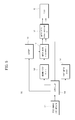
- FIG. 2 is a block diagram illustrating the configuration of the electric bicycle driving apparatus according to the first embodiment of the present invention.
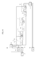
- FIG. 3 is an equivalent circuit diagram illustrating an example of the electric bicycle driving apparatus according to the first embodiment of the present invention
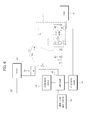
- FIG. 4 is an equivalent circuit diagram illustrating another example of the electric bicycle driving apparatus according to the first embodiment of the present invention.
- the electric bicycle driving apparatus according to the first embodiment of the present invention, denoted by reference numeral 100, is provided at one side and the other side of the electric bicycle, denoted by reference numeral 10.
- the electric bicycle driving apparatus 100 includes a speed change mode operator 102, controller 104, first motor driver 106, second motor driver 108, motor drive load booster 110, and a motor speed change switching unit 112.
- the speed change mode operator 102 is provided to output a low-speed mode signal or a high-speed mode signal.
- the speed change mode operator 102 may be provided at a portion of a handle bar of the electric bicycle 10.
- the controller 104 receives the low-speed mode signal or high-speed mode signal output from the speed change mode operator 102, and outputs a first control signal corresponding to the low-speed mode signal or a second control signal corresponding to the high-speed mode signal.
- the controller 104 may include an Electronic Controller Unit (ECU) or a Micro Controller Unit (MCU).
- ECU Electronic Controller Unit
- MCU Micro Controller Unit
- the first motor driver 106 receives the first control signal and outputs a first motor driving signal to drive a motor 101 in a low-speed mode when the speed change mode operator 102 outputs the low-speed mode signal.
- the second motor driver 108 receives the second control signal and outputs a second motor driving signal to drive the motor 101, which has been rotated by driving power of the first motor driving signal, in a high-speed mode when the speed change mode operator 102 outputs the high-speed mode signal.
- At least one of the first motor driving signal and the second motor driving signal may be a three-phase motor driving signal.
- the motor drive load booster 110 receives power from a battery 103 under control of the controller 104, and boosts load of the second motor driving signal output from the second motor driver 108 to thereby output the signal having the boosted load when the speed change mode operator 102 outputs the high-speed mode signal.
- the motor drive load booster 110 may include a first motor drive load booster 110a and a second motor drive load booster 110b.
- the first motor drive load booster 110a may include more than one first capacitor C1, more than one first resistor R1, and more than one second resistor R2.
- the more than one first capacitor C1 may be electrically connected to the battery 103, and in turn the more than one first resistor R1 may be electrically connected to the more than one first capacitor C1.
- the more than one second resistor R2 may be electrically connected to the more than one first resistor R1 and second motor driver 108.
- the more than one first resistor R1 and more than one second resistor R2 may be partial-pressure resistors.
- the first motor drive load booster 110a may further include more than one zener diode ZD1, which is electrically connected to the battery 103 and more than one first capacitor C1 to cut off an abnormal signal from the battery 103.
- the second motor drive load booster 110b may include more than one third resistor R3, more than one fourth resistor R4, and more than one fourth rectifying diode D4.
- the more than one third resistor R3 may be electrically connected to the second motor driver 108, and the more than one fourth resistor R4 may be electrically connected to the more than one third resistor R3 and motor speed change switching unit 112 that will be described hereinafter.
- the more than one fourth rectifying diode D4 may be electrically connected to the second motor driver 108 and more than one third resistor R3.
- the second motor drive load booster 110b may further include more than one zener diode ZD2, which is electrically connected to the more than one fourth rectifying diode D4, more than one third resistor R3 and more than one fourth resistor R4 to cut off an abnormal signal from the motor speed change switching unit 112 that will be described hereinafter.
- the motor drive load booster 100; 100a and 100b may create a first current-path between the more than one first capacitor C1, more than one first resistor R1 and more than one second resistor R2, and a second current-path between the more than one third resistor R3, more than one fourth resistor R4 and more than one fourth rectifying diode D4.
- the motor drive load booster 100; 100a and 100b receives power from the battery 103 and boosts load so as to enable rapid output of the second motor driving signal from the second motor driver 108 under control of the controller 104.
- the motor speed change switching unit 112 is turned on upon selectively receiving a switching enable signal from the controller 104, and provides the second motor driving signal having the boosted load to the motor 101.
- the motor speed change switching unit 112 may include more than one first rectifying diode D1, first switching device SW1, more than one fifth resistor R5, more than one second rectifying diode D2, second switching device SW2, and more than one sixth resistor R6.
- the more than one first rectifying diode D1 may be electrically connected to one side of the speed change mode operator 102, and the first switching device SW1 may be electrically connected to the more than one first rectifying diode D1 and motor drive load booster 110.
- the first switching device SW1 may include at least one of a Metal-Oxide Semiconductor Field Effect Transistor (MOSFET) and a Bipolar Junction Transistor (BJT).
- MOSFET Metal-Oxide Semiconductor Field Effect Transistor
- BJT Bipolar Junction Transistor
- the first switching device SW1 may further include more than one zener diode ZD9, which is electrically connected to the more than one fifth resistor R5 and second switching device SW2 to cut off an abnormal signal from the motor 101.
- the motor speed change switching unit 112 may further include more than one zener diode ZD3 and ZD4, which is electrically connected to the motor drive load booster 110 and more than one fifth resistor R5 to cut off an abnormal signal from at least one of the controller 104, motor drive load booster 110 and motor 101.
- the more than one fifth resistor R5 may be electrically connected to the more than one first rectifying diode D1, first switching device SW1 and motor drive load booster 110, and the more than one second rectifying diode D2 may be electrically connected to the other side of the speed change mode operator 102.
- the second switching device SW2 may be electrically connected to the more than one second rectifying diode D2 and first switching device SW1, and the more than one sixth resistor R6 may be electrically connected to the more than one second rectifying diode D2, second switching device SW2 and motor 101.
- the second switching device SW2 may include at least one of an MOSFET and a BJT.
- the second switching device SW2 may further include more than one zener diode ZD10, which is electrically connected to the first switching device SW1 and more than one sixth resistor R6 to cut off an abnormal signal from the motor drive load booster 110.
- the motor speed change switching unit 112 may further include more than one zener diode ZD5 and ZD6, which is electrically connected to the more than one sixth resistor R6 and motor 101 to cut off an abnormal signal from at least one of the motor drive load booster 110 and motor 101.
- the method to drive the electric bicycle 10 using the electric bicycle driving apparatus 100 includes receiving a first control signal from the controller 104 and outputting a first motor driving signal from the first motor driver 106 to drive the motor 101 in a low-speed mode when the speed change mode operator 102 outputs a low-speed mode signal.
- the method to drive the electric bicycle 10 using the electric bicycle driving apparatus 100 includes receiving a second control signal from the controller 104 and outputting a second motor driving signal from the second motor driver 108 to drive the motor 101, which has been rotated by driving power of the first motor driving signal, in a high-speed mode when the speed change mode operator 102 outputs a high-speed mode signal.
- the method to drive the electric bicycle 10 using the electric bicycle driving apparatus 100 includes receiving power from the battery 103 under control of the controller 104 and boosting load of the second motor driving signal output from the second motor driver 108 to thereby output the signal having the boosted signal when the speed change mode operator 102 outputs the high-speed mode signal.
- the method to drive the electric bicycle 10 using the electric bicycle driving apparatus 100 includes turning on the motor speed change switching unit 112 upon selectively receiving a switching enable signal from the controller 104 to provide the second motor driving signal having the boosted load to the motor 101.
- the electric bicycle driving apparatus 100 includes the speed change mode operator 102, controller 104, first motor driver 106, second motor driver 108, motor drive load booster 110, and a motor speed change switching unit 112.
- the electric bicycle driving apparatus 100 may provide the second motor driving signal having the boosted load from the motor drive load booster 110 to the motor 101 as the motor speed change switching unit 112 is turned on when the first motor driving signal or second motor driving signal output from the first motor driver 106 or second motor driver 108 is applied to the motor 101 for a speed change mode.
- the electric bicycle driving apparatus 100 may achieve rapid switching response of the load boosted via the motor drive load booster 110 and turning-on of the motor speed change switching unit 112 when the motor 101 is driven in a speed change mode, which may reduce a speed change mode time in consideration of battery power consumption.
- FIG. 5 is a block diagram illustrating a configuration of the electric bicycle driving apparatus according to the second embodiment of the present invention
- FIG. 6 is an equivalent circuit diagram illustrating an example of the electric bicycle driving apparatus according to the second embodiment of the present invention.
- FIG. 7 is an equivalent circuit diagram illustrating another example of the electric bicycle driving apparatus according to the second embodiment of the present invention.
- the electric bicycle driving apparatus 500 includes the speed change mode operator 102, controller 104, first motor driver 106, second motor driver 108, motor drive load booster 110, and a motor speed change switching unit 512.
- the speed change mode operator 102 is provided to output a low-speed mode signal or a high-speed mode signal.
- the speed change mode operator 102 may be provided at a portion of a handle bar of the electric bicycle 10.
- the controller 104 receives the low-speed mode signal or high-speed mode signal output from the speed change mode operator 101, and outputs a first control signal corresponding to the low-speed mode signal or a second control signal corresponding to the high-speed mode signal.
- the controller 104 may include an ECU or an MCU.
- the first motor driver 106 receives the first control signal, and outputs a first motor driving signal to drive the motor 101 in a low-speed mode when the speed change mode operator 102 outputs the low-speed mode signal.
- the second motor driver 108 receives the second control signal and outputs a second motor driving signal to drive the motor 101, which has been rotated by driving power of the first motor driving signal, in a high-speed mode when the speed change mode operator 102 outputs the high-speed mode signal.
- At least one of the first motor driving signal and the second motor driving signal may be a three-phase motor driving signal.
- the motor drive load booster 110 receives power from the battery 103 under control of the controller 104, and boosts load of the second motor driving signal output from the second motor driver 108 to thereby output the resulting signal when the speed change mode operator 102 outputs the high-speed mode signal.
- the motor drive load booster 110 may include the first motor drive load booster 110a and second motor drive load booster 110b.
- the first motor drive load booster 110a may include the more than one first capacitor C1, more than one first resistor R1, and more than one second resistor R2.
- the more than one first capacitor C1 may be electrically connected to the battery 103, and in turn the more than one first resistor R1 may be electrically connected to the more than one first capacitor C1.
- the more than one second resistor R2 may be electrically connected to the more than one first resistor R1 and second motor driver 108.
- the more than one first resistor R1 and more than one second resistor R2 may be partial-pressure resistors.
- the first motor drive load booster 110a may further include the more than one zener diode ZD1, which is electrically connected to the battery 103 and more than one first capacitor C1 to cut off an abnormal signal from the battery 103.
- the second motor drive load booster 110b may include the more than one third resistor R3, more than one fourth resistor R4, and more than one fourth rectifying diode D4.
- the more than one third resistor R3 may be electrically connected to the second motor driver 108, and the more than one fourth resistor R4 may be electrically connected to the more than one third resistor R3 and motor speed change switching unit 112 that will be described hereinafter.
- the more than one fourth rectifying diode D4 may be electrically connected to the second motor driver 108 and more than one third resistor R3.
- the second motor drive load booster 110b may further include more than one zener diode ZD2, which is electrically connected to the more than one fourth rectifying diode D4, more than one third resistor R3 and more than one fourth resistor R4 to cut off an abnormal signal from the motor speed change switching unit 112 that will be described hereinafter.
- the motor drive load booster 100; 100a and 100b may create the first current-path between the more than one first capacitor C1, more than one first resistor R1 and more than one second resistor R2, and the second current-path between the more than one third resistor R3, more than one fourth resistor R4 and more than one fourth rectifying diode D4.
- the motor drive load booster 100; 100a and 100b receives power from the battery 103 and boosts load so as to enable rapid output of the second motor driving signal from the second motor driver 108 under control of the controller 104.
- the motor speed change switching unit 512 may include more than one third rectifying diode D3, third switching device SW3, more than one seventh resistor R7, and fourth switching device SW4.
- the more than one third rectifying diode D3 may be electrically connected to one side of the speed change mode operator 102, and the third switching device SW3 may be electrically connected to the more than one third rectifying diode D1 and motor drive load booster 110.
- the third switching device SW3 may include at least one of an MOSFET and a BJT.
- the third switching device SW3 may further include more than one zener diode ZD11, which is electrically connected to the motor drive load booster 110 and more than one seventh resistor R7 to cut off an abnormal signal from the motor 101.
- the more than one seventh resistor R7 may be electrically connected to the more than one third rectifying diode D3 and third switching device SW3, and the fourth switching device SW4 may be electrically connected to the more than one third rectifying diode D3, more than one seventh resistor R7 and motor 101.
- the fourth switching device SW4 may include at least one of an MOSFET and a BJT.
- the fourth switching device SW4 may further include more than one zener diode ZD12, which is electrically connected to the more than one seventh resistor R7 and motor 101 to cut off an abnormal signal from the motor drive load booster 110.
- the motor speed change switching unit 512 may further include more than one zener diode ZD7 and ZD8, which is electrically connected to the more than one seventh resistor R7, more than one third rectifying diode D3 and fourth switching device SW4 to cut off an abnormal signal from at least one of the controller 104, motor drive load booster 110 and motor 101.
- the method to drive the electric bicycle (10, see FIG. 1 ) using the electric bicycle driving apparatus 500 includes receiving a first control signal from the controller 104 and outputting a first motor driving signal from the first motor driver 106 to drive the motor 101 in a low-speed mode when the speed change mode operator 102 outputs a low-speed mode signal.
- the method to drive the electric bicycle (10, see FIG.1 ) using the electric bicycle driving apparatus 500 according to the second embodiment of the present invention includes receiving a second control signal from the controller 104 and outputting a second motor driving signal from the second motor driver 108 to drive the motor 101, which has been rotated by driving power of the first motor driving signal, in a high-speed mode when the speed change mode operator 102 outputs a high-speed mode signal.
- the method to drive the electric bicycle (10, see FIG. 1 ) using the electric bicycle driving apparatus 500 according to the second embodiment of the present invention includes receiving power from the battery 103 under control of the controller 104 and boosting load of the second motor driving signal output from the second motor driver 108 to thereby output the resulting signal when the speed change mode operator 102 outputs the high-speed mode signal.
- the method to drive the electric bicycle (10, see FIG. 1 ) using the electric bicycle driving apparatus 500 according to the first embodiment of the present invention includes turning on the motor speed change switching unit 512 upon selectively receiving a switching enable signal from the controller 104 to provide the second motor driving signal having the boosted load to the motor 101.
- the electric bicycle driving apparatus 500 includes the speed change mode operator 102, controller 104, first motor driver 106, second motor driver 108, motor drive load booster 110, and a motor speed change switching unit 512.
- the electric bicycle driving apparatus 500 may provide the second motor driving signal having the boosted load from the motor drive load booster 110 to the motor 101 as the motor speed change switching unit 512 is turned on when the first motor driving signal or second motor driving signal output from the first motor driver 106 or second motor driver 108 is applied to the motor 101 for a speed change mode.
- the electric bicycle driving apparatus 500 may achieve rapid switching response of the load boosted via the motor drive load booster 110 and turning-on of the motor speed change switching unit 512 when the motor 101 is driven in a speed change mode, which may reduce a speed change mode time in consideration of battery power consumption.
Landscapes
- Engineering & Computer Science (AREA)
- Transportation (AREA)
- Mechanical Engineering (AREA)
- Power Engineering (AREA)
- Chemical & Material Sciences (AREA)
- Combustion & Propulsion (AREA)
- Life Sciences & Earth Sciences (AREA)
- Sustainable Development (AREA)
- Sustainable Energy (AREA)
- Electric Propulsion And Braking For Vehicles (AREA)
- Control Of Electric Motors In General (AREA)
Abstract
Description
- This application claims the benefit of Korean Patent Application No.
2012-0104167, filed on September 19, 2012 - Embodiments of the present invention relate to an electric bicycle driving apparatus.
- In general, electric bicycle driving apparatuses are provided to drive electric bicycles.
- Most conventional driving apparatuses for electric bicycles have a limit to effective operation of a motor driver that drives a motor in a low-speed or high-speed motor driving mode, and consequently have a limit to reduction in battery power consumption.
- Recently, studies into improved electric bicycle driving apparatuses to reduce a speed change mode time in consideration of battery power consumption when a motor of an electric bicycle is driven in a low-speed mode or high-speed mode have been performed.
- Therefore, it is an aspect of the present invention to provide an electric bicycle driving apparatus which may rapidly reduce a speed change mode time in consideration of battery power consumption.
- Additional aspects of the invention will be set forth in part in the description which follows and, in part, will be obvious from the description, or may be learned by practice of the invention.
- In accordance with one aspect of the present invention, an bicycle driving apparatus includes a speed change mode operator to output a low-speed mode signal or a high-speed mode signal, a controller to receive the low-speed mode signal or high-speed mode signal output from the speed change mode operator and output a first control signal corresponding to the low-speed mode signal or a second control signal corresponding to the high-speed mode signal, a first motor driver to receive the first control signal and output a first motor driving signal to drive a motor in a low-speed mode when the speed change mode operator outputs the low-speed mode signal, a second motor driver to receive the second control signal and output a second motor driving signal to drive the motor, which has been rotated by driving power of the first motor driving signal, in a high-speed mode when the speed change mode operator outputs the high-speed mode signal, a motor drive load booster to receive battery power from a battery under control of the controller and boost load of the second motor driving signal output from the second motor driver to output the signal having the boosted load when the speed change mode operator outputs the high-speed mode signal, and a motor speed change switching unit to selectively receive a switching enable signal from the controller so as to be turned on to provide the second motor driving signal having the boosted load to the motor.
- The motor drive load booster may include more than one first capacitor electrically connected to the battery, more than one first resistor electrically connected to the more than one first capacitor, and more than one second resistor electrically connected to the more than one first resistor and second motor driver.
- The motor drive load booster may further include more than one zener diode electrically connected to the battery and more than one first capacitor.
- The motor drive load booster may include more than one third resistor electrically connected to the second motor driver, more than one fourth resistor electrically connected to the more than one third resistor and motor speed change switching unit, and more than one fourth rectifying diode electrically connected to the second motor driver and more than one third resistor.
- The motor drive load booster may further include more than one zener diode electrically connected to the more than one fourth rectifying diode, more than one third resistor and more than one fourth resistor.
- The motor speed change switching unit may include more than one first rectifying diode electrically connected to one side of the speed change mode operator, a first switching device electrically connected to the more than one first rectifying diode and motor drive load booster, more than one fifth resistor electrically connected to the more than one first rectifying diode, first switching device, and motor drive load booster, more than one second rectifying diode electrically connected to the other side of the speed change mode operator, a second switching device electrically connected to the more than one second rectifying diode and first switching device, and more than one sixth resistor electrically connected to the more than one second rectifying diode, second switching device and motor.
- Each of the first switching device and second switching device may include at least one of a Metal-Oxide Semiconductor Field Effect Transistor (MOSFET) and a Bipolar Junction Transistor (BJT).
- The first switching device may further include more than one zener diode electrically connected to the more than one fifth resistor and second switching device.
- The second switching device may further include more than one zener diode electrically connected to the first switching device and more than one sixth resistor.
- The motor speed change switching unit may further include more than one zener diode electrically connected to the motor drive load booster and more than one fifth resistor.
- The motor speed change switching unit may further include more than one zener diode electrically connected to the more than one sixth resistor and motor.
- The motor speed change switching unit may include more than one third rectifying diode electrically connected to one side of the speed change mode operator, a third switching device electrically connected to the more than one third rectifying diode and motor drive load booster, more than one seventh resistor electrically connected to the more than one third rectifying diode and third switching device, and a fourth switching device electrically connected to the more than one third rectifying diode, more than one seventh resistor and motor.
- Each of the third switching device and fourth switching device may include at least one of an MOSFET and a BJT.
- The third switching device may further include more than one zener diode electrically connected to the motor drive load booster and more than one seventh resistor.
- The fourth switching device may further include more than one zener diode electrically connected to the more than one seventh resistor and motor.
- The motor speed change switching unit may further include more than one zener diode electrically connected to the more than one seventh resistor, more than one third rectifying diode, and fourth switching device.
- These and/or other aspects of the invention will become apparent and more readily appreciated from the following description of the embodiments, taken in conjunction with the accompanying drawings of which:
-
FIG. 1 is a perspective view illustrating an electric bicycle including an electric bicycle driving apparatus according to a first embodiment of the present invention; -
FIG. 2 is a block diagram illustrating the configuration of the electric bicycle driving apparatus according to the first embodiment of the present invention; -
FIG. 3 is an equivalent circuit diagram illustrating an example of the electric bicycle driving apparatus according to the first embodiment of the present invention; -
FIG. 4 is an equivalent circuit diagram illustrating another example of the electric bicycle driving apparatus according to the first embodiment of the present invention; -
FIG. 5 is a block diagram illustrating a configuration of the electric bicycle driving apparatus according to the second embodiment of the present invention; -
FIG. 6 is an equivalent circuit diagram illustrating an example of the electric bicycle driving apparatus according to the second embodiment of the present invention; and -
FIG. 7 is an equivalent circuit diagram illustrating another example of the electric bicycle driving apparatus according to the second embodiment of the present invention. - Reference will now be made in detail to the embodiments of the present invention, examples of which are illustrated in the accompanying drawings, wherein like reference numerals refer to like elements throughout.
-
FIG. 1 is a perspective view illustrating an electric bicycle including an electric bicycle driving apparatus according to a first embodiment of the present invention, andFIG. 2 is a block diagram illustrating the configuration of the electric bicycle driving apparatus according to the first embodiment of the present invention. -
FIG. 3 is an equivalent circuit diagram illustrating an example of the electric bicycle driving apparatus according to the first embodiment of the present invention, andFIG. 4 is an equivalent circuit diagram illustrating another example of the electric bicycle driving apparatus according to the first embodiment of the present invention. - First, referring to
FIG. 1 , the electric bicycle driving apparatus according to the first embodiment of the present invention, denoted byreference numeral 100, is provided at one side and the other side of the electric bicycle, denoted byreference numeral 10. - Next, referring to
FIGS. 2 to 4 , the electricbicycle driving apparatus 100 according to the first embodiment of the present invention includes a speedchange mode operator 102,controller 104,first motor driver 106,second motor driver 108, motordrive load booster 110, and a motor speedchange switching unit 112. - The speed
change mode operator 102 is provided to output a low-speed mode signal or a high-speed mode signal. - The speed
change mode operator 102 may be provided at a portion of a handle bar of theelectric bicycle 10. - The
controller 104 receives the low-speed mode signal or high-speed mode signal output from the speedchange mode operator 102, and outputs a first control signal corresponding to the low-speed mode signal or a second control signal corresponding to the high-speed mode signal. - The
controller 104 may include an Electronic Controller Unit (ECU) or a Micro Controller Unit (MCU). - The
first motor driver 106 receives the first control signal and outputs a first motor driving signal to drive amotor 101 in a low-speed mode when the speedchange mode operator 102 outputs the low-speed mode signal. - The
second motor driver 108 receives the second control signal and outputs a second motor driving signal to drive themotor 101, which has been rotated by driving power of the first motor driving signal, in a high-speed mode when the speedchange mode operator 102 outputs the high-speed mode signal. - At least one of the first motor driving signal and the second motor driving signal may be a three-phase motor driving signal.
- The motor
drive load booster 110 receives power from abattery 103 under control of thecontroller 104, and boosts load of the second motor driving signal output from thesecond motor driver 108 to thereby output the signal having the boosted load when the speedchange mode operator 102 outputs the high-speed mode signal. - In one example, as illustrated in
FIGS. 3 and4 , the motordrive load booster 110 may include a first motordrive load booster 110a and a second motordrive load booster 110b. - The first motor
drive load booster 110a may include more than one first capacitor C1, more than one first resistor R1, and more than one second resistor R2. - The more than one first capacitor C1 may be electrically connected to the
battery 103, and in turn the more than one first resistor R1 may be electrically connected to the more than one first capacitor C1. - The more than one second resistor R2 may be electrically connected to the more than one first resistor R1 and
second motor driver 108. - The more than one first resistor R1 and more than one second resistor R2 may be partial-pressure resistors.
- The first motor
drive load booster 110a may further include more than one zener diode ZD1, which is electrically connected to thebattery 103 and more than one first capacitor C1 to cut off an abnormal signal from thebattery 103. - The second motor
drive load booster 110b may include more than one third resistor R3, more than one fourth resistor R4, and more than one fourth rectifying diode D4. - The more than one third resistor R3 may be electrically connected to the
second motor driver 108, and the more than one fourth resistor R4 may be electrically connected to the more than one third resistor R3 and motor speedchange switching unit 112 that will be described hereinafter. - The more than one fourth rectifying diode D4 may be electrically connected to the
second motor driver 108 and more than one third resistor R3. - The second motor
drive load booster 110b may further include more than one zener diode ZD2, which is electrically connected to the more than one fourth rectifying diode D4, more than one third resistor R3 and more than one fourth resistor R4 to cut off an abnormal signal from the motor speedchange switching unit 112 that will be described hereinafter. - The motor
drive load booster 100; 100a and 100b may create a first current-path between the more than one first capacitor C1, more than one first resistor R1 and more than one second resistor R2, and a second current-path between the more than one third resistor R3, more than one fourth resistor R4 and more than one fourth rectifying diode D4. Thereby, when the speedchange mode operator 102 outputs a high-speed mode signal, the motordrive load booster 100; 100a and 100b receives power from thebattery 103 and boosts load so as to enable rapid output of the second motor driving signal from thesecond motor driver 108 under control of thecontroller 104. - The motor speed
change switching unit 112 is turned on upon selectively receiving a switching enable signal from thecontroller 104, and provides the second motor driving signal having the boosted load to themotor 101. - The motor speed
change switching unit 112 may include more than one first rectifying diode D1, first switching device SW1, more than one fifth resistor R5, more than one second rectifying diode D2, second switching device SW2, and more than one sixth resistor R6. - The more than one first rectifying diode D1 may be electrically connected to one side of the speed
change mode operator 102, and the first switching device SW1 may be electrically connected to the more than one first rectifying diode D1 and motordrive load booster 110. - The first switching device SW1 may include at least one of a Metal-Oxide Semiconductor Field Effect Transistor (MOSFET) and a Bipolar Junction Transistor (BJT).
- The first switching device SW1 may further include more than one zener diode ZD9, which is electrically connected to the more than one fifth resistor R5 and second switching device SW2 to cut off an abnormal signal from the
motor 101. - The motor speed
change switching unit 112 may further include more than one zener diode ZD3 and ZD4, which is electrically connected to the motordrive load booster 110 and more than one fifth resistor R5 to cut off an abnormal signal from at least one of thecontroller 104, motordrive load booster 110 andmotor 101. - The more than one fifth resistor R5 may be electrically connected to the more than one first rectifying diode D1, first switching device SW1 and motor
drive load booster 110, and the more than one second rectifying diode D2 may be electrically connected to the other side of the speedchange mode operator 102. - The second switching device SW2 may be electrically connected to the more than one second rectifying diode D2 and first switching device SW1, and the more than one sixth resistor R6 may be electrically connected to the more than one second rectifying diode D2, second switching device SW2 and
motor 101. - The second switching device SW2 may include at least one of an MOSFET and a BJT.
- The second switching device SW2 may further include more than one zener diode ZD10, which is electrically connected to the first switching device SW1 and more than one sixth resistor R6 to cut off an abnormal signal from the motor
drive load booster 110. - The motor speed
change switching unit 112 may further include more than one zener diode ZD5 and ZD6, which is electrically connected to the more than one sixth resistor R6 andmotor 101 to cut off an abnormal signal from at least one of the motordrive load booster 110 andmotor 101. - Hereinafter, a method to drive the
electric bicycle 10 using the electricbicycle driving apparatus 100 according to the first embodiment of the present invention will be described. - First, the method to drive the
electric bicycle 10 using the electricbicycle driving apparatus 100 according to the first embodiment of the present invention includes receiving a first control signal from thecontroller 104 and outputting a first motor driving signal from thefirst motor driver 106 to drive themotor 101 in a low-speed mode when the speedchange mode operator 102 outputs a low-speed mode signal. - Thereafter, the method to drive the
electric bicycle 10 using the electricbicycle driving apparatus 100 according to the first embodiment of the present invention includes receiving a second control signal from thecontroller 104 and outputting a second motor driving signal from thesecond motor driver 108 to drive themotor 101, which has been rotated by driving power of the first motor driving signal, in a high-speed mode when the speedchange mode operator 102 outputs a high-speed mode signal. - Thereafter, the method to drive the
electric bicycle 10 using the electricbicycle driving apparatus 100 according to the first embodiment of the present invention includes receiving power from thebattery 103 under control of thecontroller 104 and boosting load of the second motor driving signal output from thesecond motor driver 108 to thereby output the signal having the boosted signal when the speedchange mode operator 102 outputs the high-speed mode signal. - Finally, the method to drive the
electric bicycle 10 using the electricbicycle driving apparatus 100 according to the first embodiment of the present invention includes turning on the motor speedchange switching unit 112 upon selectively receiving a switching enable signal from thecontroller 104 to provide the second motor driving signal having the boosted load to themotor 101. - As described above, the electric
bicycle driving apparatus 100 according to the first embodiment of the present invention includes the speedchange mode operator 102,controller 104,first motor driver 106,second motor driver 108, motordrive load booster 110, and a motor speedchange switching unit 112. - Accordingly, the electric
bicycle driving apparatus 100 according to the first embodiment of the present invention may provide the second motor driving signal having the boosted load from the motordrive load booster 110 to themotor 101 as the motor speedchange switching unit 112 is turned on when the first motor driving signal or second motor driving signal output from thefirst motor driver 106 orsecond motor driver 108 is applied to themotor 101 for a speed change mode. - In this way, the electric
bicycle driving apparatus 100 according to the first embodiment of the present invention may achieve rapid switching response of the load boosted via the motordrive load booster 110 and turning-on of the motor speedchange switching unit 112 when themotor 101 is driven in a speed change mode, which may reduce a speed change mode time in consideration of battery power consumption. -
FIG. 5 is a block diagram illustrating a configuration of the electric bicycle driving apparatus according to the second embodiment of the present invention, andFIG. 6 is an equivalent circuit diagram illustrating an example of the electric bicycle driving apparatus according to the second embodiment of the present invention. -
FIG. 7 is an equivalent circuit diagram illustrating another example of the electric bicycle driving apparatus according to the second embodiment of the present invention. - Referring to
FIGS. 5 to 7 , the electricbicycle driving apparatus 500 according to the second embodiment of the present invention includes the speedchange mode operator 102,controller 104,first motor driver 106,second motor driver 108, motordrive load booster 110, and a motor speedchange switching unit 512. - The speed
change mode operator 102 is provided to output a low-speed mode signal or a high-speed mode signal. - The speed
change mode operator 102 may be provided at a portion of a handle bar of theelectric bicycle 10. - The
controller 104 receives the low-speed mode signal or high-speed mode signal output from the speedchange mode operator 101, and outputs a first control signal corresponding to the low-speed mode signal or a second control signal corresponding to the high-speed mode signal. - The
controller 104 may include an ECU or an MCU. - The
first motor driver 106 receives the first control signal, and outputs a first motor driving signal to drive themotor 101 in a low-speed mode when the speedchange mode operator 102 outputs the low-speed mode signal. - The
second motor driver 108 receives the second control signal and outputs a second motor driving signal to drive themotor 101, which has been rotated by driving power of the first motor driving signal, in a high-speed mode when the speedchange mode operator 102 outputs the high-speed mode signal. - At least one of the first motor driving signal and the second motor driving signal may be a three-phase motor driving signal.
- The motor
drive load booster 110 receives power from thebattery 103 under control of thecontroller 104, and boosts load of the second motor driving signal output from thesecond motor driver 108 to thereby output the resulting signal when the speedchange mode operator 102 outputs the high-speed mode signal. - In one example, as illustrated in
FIGS. 6 and7 , the motordrive load booster 110 may include the first motordrive load booster 110a and second motordrive load booster 110b. - The first motor
drive load booster 110a may include the more than one first capacitor C1, more than one first resistor R1, and more than one second resistor R2. - The more than one first capacitor C1 may be electrically connected to the
battery 103, and in turn the more than one first resistor R1 may be electrically connected to the more than one first capacitor C1. - The more than one second resistor R2 may be electrically connected to the more than one first resistor R1 and
second motor driver 108. - The more than one first resistor R1 and more than one second resistor R2 may be partial-pressure resistors.
- The first motor
drive load booster 110a may further include the more than one zener diode ZD1, which is electrically connected to thebattery 103 and more than one first capacitor C1 to cut off an abnormal signal from thebattery 103. - The second motor
drive load booster 110b may include the more than one third resistor R3, more than one fourth resistor R4, and more than one fourth rectifying diode D4. - The more than one third resistor R3 may be electrically connected to the
second motor driver 108, and the more than one fourth resistor R4 may be electrically connected to the more than one third resistor R3 and motor speedchange switching unit 112 that will be described hereinafter. - The more than one fourth rectifying diode D4 may be electrically connected to the
second motor driver 108 and more than one third resistor R3. - The second motor
drive load booster 110b may further include more than one zener diode ZD2, which is electrically connected to the more than one fourth rectifying diode D4, more than one third resistor R3 and more than one fourth resistor R4 to cut off an abnormal signal from the motor speedchange switching unit 112 that will be described hereinafter. - The motor
drive load booster 100; 100a and 100b may create the first current-path between the more than one first capacitor C1, more than one first resistor R1 and more than one second resistor R2, and the second current-path between the more than one third resistor R3, more than one fourth resistor R4 and more than one fourth rectifying diode D4. Thereby, when the speedchange mode operator 102 outputs a high-speed mode signal, the motordrive load booster 100; 100a and 100b receives power from thebattery 103 and boosts load so as to enable rapid output of the second motor driving signal from thesecond motor driver 108 under control of thecontroller 104. - The motor speed
change switching unit 512 may include more than one third rectifying diode D3, third switching device SW3, more than one seventh resistor R7, and fourth switching device SW4. - The more than one third rectifying diode D3 may be electrically connected to one side of the speed
change mode operator 102, and the third switching device SW3 may be electrically connected to the more than one third rectifying diode D1 and motordrive load booster 110. - The third switching device SW3 may include at least one of an MOSFET and a BJT.
- The third switching device SW3 may further include more than one zener diode ZD11, which is electrically connected to the motor
drive load booster 110 and more than one seventh resistor R7 to cut off an abnormal signal from themotor 101. - The more than one seventh resistor R7 may be electrically connected to the more than one third rectifying diode D3 and third switching device SW3, and the fourth switching device SW4 may be electrically connected to the more than one third rectifying diode D3, more than one seventh resistor R7 and
motor 101. - The fourth switching device SW4 may include at least one of an MOSFET and a BJT.
- The fourth switching device SW4 may further include more than one zener diode ZD12, which is electrically connected to the more than one seventh resistor R7 and
motor 101 to cut off an abnormal signal from the motordrive load booster 110. - The motor speed
change switching unit 512 may further include more than one zener diode ZD7 and ZD8, which is electrically connected to the more than one seventh resistor R7, more than one third rectifying diode D3 and fourth switching device SW4 to cut off an abnormal signal from at least one of thecontroller 104, motordrive load booster 110 andmotor 101. - Hereinafter, a method to drive the electric bicycle (10, see
FIG. 1 ) using the electricbicycle driving apparatus 500 according to the second embodiment of the present invention will be described. - First, the method to drive the electric bicycle (10, see
FIG. 1 ) using the electricbicycle driving apparatus 500 according to the second embodiment of the present invention includes receiving a first control signal from thecontroller 104 and outputting a first motor driving signal from thefirst motor driver 106 to drive themotor 101 in a low-speed mode when the speedchange mode operator 102 outputs a low-speed mode signal. - Thereafter, the method to drive the electric bicycle (10, see
FIG.1 ) using the electricbicycle driving apparatus 500 according to the second embodiment of the present invention includes receiving a second control signal from thecontroller 104 and outputting a second motor driving signal from thesecond motor driver 108 to drive themotor 101, which has been rotated by driving power of the first motor driving signal, in a high-speed mode when the speedchange mode operator 102 outputs a high-speed mode signal. - Thereafter, the method to drive the electric bicycle (10, see
FIG. 1 ) using the electricbicycle driving apparatus 500 according to the second embodiment of the present invention includes receiving power from thebattery 103 under control of thecontroller 104 and boosting load of the second motor driving signal output from thesecond motor driver 108 to thereby output the resulting signal when the speedchange mode operator 102 outputs the high-speed mode signal. - Finally, the method to drive the electric bicycle (10, see
FIG. 1 ) using the electricbicycle driving apparatus 500 according to the first embodiment of the present invention includes turning on the motor speedchange switching unit 512 upon selectively receiving a switching enable signal from thecontroller 104 to provide the second motor driving signal having the boosted load to themotor 101. - As described above, the electric
bicycle driving apparatus 500 according to the second embodiment of the present invention includes the speedchange mode operator 102,controller 104,first motor driver 106,second motor driver 108, motordrive load booster 110, and a motor speedchange switching unit 512. - Accordingly, the electric
bicycle driving apparatus 500 according to the second embodiment of the present invention may provide the second motor driving signal having the boosted load from the motordrive load booster 110 to themotor 101 as the motor speedchange switching unit 512 is turned on when the first motor driving signal or second motor driving signal output from thefirst motor driver 106 orsecond motor driver 108 is applied to themotor 101 for a speed change mode. - In this way, the electric
bicycle driving apparatus 500 according to the second embodiment of the present invention may achieve rapid switching response of the load boosted via the motordrive load booster 110 and turning-on of the motor speedchange switching unit 512 when themotor 101 is driven in a speed change mode, which may reduce a speed change mode time in consideration of battery power consumption. - Although a few embodiments of the present invention have been shown and described, it would be appreciated by those skilled in the art that changes may be made in these embodiments without departing from the principles and spirit of the invention, the scope of which is defined in the claims and their equivalents.
Claims (14)
- An electric bicycle driving apparatus comprising:a speed change mode operator to output a low-speed mode signal or a high-speed mode signal;a controller to receive the low-speed mode signal or high-speed mode signal output from the speed change mode operator and output a first control signal corresponding to the low-speed mode signal or a second control signal corresponding to the high-speed mode signal;a first motor driver to receive the first control signal and output a first motor driving signal to drive a motor in a low-speed mode when the speed change mode operator outputs the low-speed mode signal;a second motor driver to receive the second control signal and output a second motor driving signal to drive the motor, which has been rotated by driving power of the first motor driving signal, in a high-speed mode when the speed change mode operator outputs the high-speed mode signal;a motor drive load booster to receive battery power from a battery under control of the controller and boost load of the second motor driving signal output from the second motor driver to output the signal having the boosted load when the speed change mode operator outputs the high-speed mode signal; anda motor speed change switching unit to selectively receive a switching enable signal from the controller so as to be turned on to provide the second motor driving signal having the boosted load to the motor.
- The apparatus according to claim 1, wherein the motor drive load booster includes:more than one first capacitor electrically connected to the battery;more than one first resistor electrically connected to the more than one first capacitor; andmore than one second resistor electrically connected to the more than one first resistor and second motor driver.
- The apparatus according to claim 2, wherein the motor drive load booster further includes more than one zener diode electrically connected to the battery and more than one first capacitor.
- The apparatus according to claim 1, wherein the motor drive load booster includes:more than one third resistor electrically connected to the second motor driver;more than one fourth resistor electrically connected to the more than one third resistor and motor speed change switching unit; andmore than one fourth rectifying diode electrically connected to the second motor driver and more than one third resistor.
- The apparatus according to claim 4, wherein the motor drive load booster further includes more than one zener diode electrically connected to the more than one fourth rectifying diode, more than one third resistor and more than one fourth resistor.
- The apparatus according to claim 1, wherein the motor speed change switching unit includes:more than one first rectifying diode electrically connected to one side of the speed change mode operator;a first switching device electrically connected to the more than one first rectifying diode and motor drive load booster;more than one fifth resistor electrically connected to the more than one first rectifying diode, first switching device, and motor drive load booster;more than one second rectifying diode electrically connected to the other side of the speed change mode operator;a second switching device electrically connected to the more than one second rectifying diode and first switching device; andmore than one sixth resistor electrically connected to the more than one second rectifying diode, second switching device and motor.
- The apparatus according to claim 6, wherein the first switching device further includes more than one zener diode electrically connected to the more than one fifth resistor and second switching device.
- The apparatus according to claim 6, wherein the second switching device further includes more than one zener diode electrically connected to the first switching device and more than one sixth resistor.
- The apparatus according to claim 6, wherein the motor speed change switching unit further includes more than one zener diode electrically connected to the motor drive load booster and more than one fifth resistor.
- The apparatus according to claim 6, wherein the motor speed change switching unit further includes more than one zener diode electrically connected to the more than one sixth resistor and motor.
- The apparatus according to claim 1, wherein the motor speed change switching unit includes:more than one third rectifying diode electrically connected to one side of the speed change mode operator;a third switching device electrically connected to the more than one third rectifying diode and motor drive load booster;more than one seventh resistor electrically connected to the more than one third rectifying diode and third switching device; anda fourth switching device electrically connected to the more than one third rectifying diode, more than one seventh resistor and motor.
- The apparatus according to claim 11, wherein the third switching device further includes more than one zener diode electrically connected to the motor drive load booster and more than one seventh resistor.
- The apparatus according to claim 11, wherein the fourth switching device further includes more than one zener diode electrically connected to the more than one seventh resistor and motor.
- The apparatus according to claim 11, wherein the motor speed change switching unit further includes more than one zener diode electrically connected to the more than one seventh resistor, more than one third rectifying diode, and fourth switching device.
Applications Claiming Priority (1)
| Application Number | Priority Date | Filing Date | Title |
|---|---|---|---|
| KR1020120104167A KR20140038043A (en) | 2012-09-19 | 2012-09-19 | Apparatus for driving electric bicycle |
Publications (2)
| Publication Number | Publication Date |
|---|---|
| EP2711237A2 true EP2711237A2 (en) | 2014-03-26 |
| EP2711237A3 EP2711237A3 (en) | 2017-10-11 |
Family
ID=47221138
Family Applications (1)
| Application Number | Title | Priority Date | Filing Date |
|---|---|---|---|
| EP12190190.4A Withdrawn EP2711237A3 (en) | 2012-09-19 | 2012-10-26 | Electric bicycle driving apparatus |
Country Status (4)
| Country | Link |
|---|---|
| US (1) | US8994301B2 (en) |
| EP (1) | EP2711237A3 (en) |
| KR (1) | KR20140038043A (en) |
| CN (1) | CN103661768B (en) |
Families Citing this family (4)
| Publication number | Priority date | Publication date | Assignee | Title |
|---|---|---|---|---|
| US8738745B1 (en) * | 2010-03-31 | 2014-05-27 | Amazon Technologies, Inc. | Managing use of intermediate destination hardware devices for provided computer networks |
| US9496708B2 (en) * | 2014-04-07 | 2016-11-15 | Allegro Microsystems, Llc | Electric motor drive isolation circuit |
| US10084407B2 (en) | 2015-11-13 | 2018-09-25 | Allegro Microsystems, Llc | Circuits and techniques for voltage monitoring of a solid-state isolator |
| CN120677629A (en) * | 2023-03-28 | 2025-09-19 | 西门子股份公司 | Motor driver |
Family Cites Families (15)
| Publication number | Priority date | Publication date | Assignee | Title |
|---|---|---|---|---|
| US3915250A (en) * | 1974-03-22 | 1975-10-28 | Sunwood Corp | Auxiliary drive for bicycle |
| DE3218594A1 (en) * | 1982-05-17 | 1983-12-22 | Braun Ag, 6000 Frankfurt | ELECTRONIC SWITCHING POWER SUPPLY |
| CN1050576C (en) * | 1993-09-14 | 2000-03-22 | 株式会社利肯 | electric bicycle |
| JPH08258782A (en) * | 1995-03-27 | 1996-10-08 | Sanyo Electric Co Ltd | Motor-driven bicycle |
| JPH09219908A (en) * | 1996-02-13 | 1997-08-19 | Yamaha Motor Co Ltd | Motor control device for electric vehicle |
| US6175765B1 (en) * | 1997-03-05 | 2001-01-16 | Medtronic Physio-Control Manufacturing Corp. | H-bridge circuit for generating a high-energy biphasic waveform in an external defibrillator |
| JPH1127981A (en) * | 1997-05-09 | 1999-01-29 | Canon Inc | Motor drive control device |
| TW409105B (en) * | 1997-07-22 | 2000-10-21 | Honda Motor Co Ltd | Auxiliary power control unit for auxiliary electromotive bicycle |
| TW364070B (en) * | 1997-12-17 | 1999-07-11 | Fuji Photo Film Kk | Lens-fitted photo film unit and flash device |
| US6396137B1 (en) * | 2000-03-15 | 2002-05-28 | Kevin Mark Klughart | Integrated voltage/current/power regulator/switch system and method |
| US7016203B2 (en) * | 2003-01-24 | 2006-03-21 | Virginia Tech Intellectual Properties, Inc. | Self-driven circuit for synchronous rectifier DC/DC converter |
| GB0902356D0 (en) * | 2009-02-12 | 2009-04-01 | Nexxtdrive Ltd | Bicycle transmission systems |
| JP5395611B2 (en) | 2009-10-16 | 2014-01-22 | 株式会社東芝 | Ultrasonic diagnostic apparatus, image data generation apparatus, and control program for image data generation |
| US8567547B2 (en) * | 2010-03-23 | 2013-10-29 | Purdue Research Foundation | Regenerative braking method |
| US20120202649A1 (en) * | 2011-02-07 | 2012-08-09 | Clarkson University | Pedal generator electric bicycle |
-
2012
- 2012-09-19 KR KR1020120104167A patent/KR20140038043A/en not_active Withdrawn
- 2012-10-26 EP EP12190190.4A patent/EP2711237A3/en not_active Withdrawn
- 2012-11-21 US US13/683,170 patent/US8994301B2/en active Active
- 2012-12-18 CN CN201210553463.1A patent/CN103661768B/en active Active
Non-Patent Citations (1)
| Title |
|---|
| None |
Also Published As
| Publication number | Publication date |
|---|---|
| KR20140038043A (en) | 2014-03-28 |
| EP2711237A3 (en) | 2017-10-11 |
| US8994301B2 (en) | 2015-03-31 |
| CN103661768A (en) | 2014-03-26 |
| US20140077730A1 (en) | 2014-03-20 |
| CN103661768B (en) | 2016-05-25 |
Similar Documents
| Publication | Publication Date | Title |
|---|---|---|
| US20170210413A1 (en) | Power supply device and electric power steering device including power supply device | |
| JP4760850B2 (en) | Electric power steering device | |
| EP1753125A3 (en) | Vector controller for permanent magnet synchronous motor | |
| EP2991807B1 (en) | Power tool with step-up converter | |
| EP2096747A3 (en) | Motor driving apparatus | |
| EP1900605A3 (en) | Electric power steering control apparatus | |
| US9002555B2 (en) | Electric bicycle driving apparatus | |
| EP2711237A2 (en) | Electric bicycle driving apparatus | |
| EP1655829A3 (en) | Circuit arrangement and method for control of an electric motor, in particular of a wasching machine | |
| CN110871840B (en) | Vehicle control device | |
| EP1767433A3 (en) | Electric power steering apparatus | |
| EP1533210A3 (en) | Electric power steering system | |
| EP3595150A3 (en) | Power converting device, compressor including the same, and control method thereof | |
| EP1909303A3 (en) | Robot control apparatus comprising a servo amplifier having an AC/DC converter | |
| EP1632420A3 (en) | Electric power steering apparatus and voltage booster | |
| US9083270B2 (en) | Electric bicycle driving apparatus | |
| JP6411714B2 (en) | Motor drive control device and electric assist vehicle | |
| JP5299668B2 (en) | Electric tool | |
| JP2007135391A (en) | Double voltage electrical system | |
| JP4203268B2 (en) | Motor control device | |
| JP6392464B2 (en) | VEHICLE DRIVE DEVICE, VEHICLE DRIVE SYSTEM, AND CONTROL METHOD FOR VEHICLE DRIVE DEVICE | |
| JP2005217774A5 (en) | ||
| US9694695B2 (en) | Power source system | |
| US20140077743A1 (en) | Electric bicycle driving apparatus | |
| TW200507438A (en) | Brushless DC motor having a multiple speed control circuit |
Legal Events
| Date | Code | Title | Description |
|---|---|---|---|
| PUAI | Public reference made under article 153(3) epc to a published international application that has entered the european phase |
Free format text: ORIGINAL CODE: 0009012 |
|
| AK | Designated contracting states |
Kind code of ref document: A2 Designated state(s): AL AT BE BG CH CY CZ DE DK EE ES FI FR GB GR HR HU IE IS IT LI LT LU LV MC MK MT NL NO PL PT RO RS SE SI SK SM TR |
|
| AX | Request for extension of the european patent |
Extension state: BA ME |
|
| PUAL | Search report despatched |
Free format text: ORIGINAL CODE: 0009013 |
|
| AK | Designated contracting states |
Kind code of ref document: A3 Designated state(s): AL AT BE BG CH CY CZ DE DK EE ES FI FR GB GR HR HU IE IS IT LI LT LU LV MC MK MT NL NO PL PT RO RS SE SI SK SM TR |
|
| AX | Request for extension of the european patent |
Extension state: BA ME |
|
| RIC1 | Information provided on ipc code assigned before grant |
Ipc: B60L 11/18 20060101ALI20170905BHEP Ipc: B60L 15/00 20060101ALI20170905BHEP Ipc: B60L 11/00 20060101ALI20170905BHEP Ipc: B60L 15/20 20060101AFI20170905BHEP |
|
| STAA | Information on the status of an ep patent application or granted ep patent |
Free format text: STATUS: THE APPLICATION IS DEEMED TO BE WITHDRAWN |
|
| 18D | Application deemed to be withdrawn |
Effective date: 20180412 |