EP2711232A2 - Electric bicycle driving apparatus - Google Patents
Electric bicycle driving apparatus Download PDFInfo
- Publication number
- EP2711232A2 EP2711232A2 EP12190185.4A EP12190185A EP2711232A2 EP 2711232 A2 EP2711232 A2 EP 2711232A2 EP 12190185 A EP12190185 A EP 12190185A EP 2711232 A2 EP2711232 A2 EP 2711232A2
- Authority
- EP
- European Patent Office
- Prior art keywords
- motor
- speed change
- signal
- relay
- change mode
- Prior art date
- Legal status (The legal status is an assumption and is not a legal conclusion. Google has not performed a legal analysis and makes no representation as to the accuracy of the status listed.)
- Withdrawn
Links
Images


Classifications
-
- B—PERFORMING OPERATIONS; TRANSPORTING
- B62—LAND VEHICLES FOR TRAVELLING OTHERWISE THAN ON RAILS
- B62M—RIDER PROPULSION OF WHEELED VEHICLES OR SLEDGES; POWERED PROPULSION OF SLEDGES OR SINGLE-TRACK CYCLES; TRANSMISSIONS SPECIALLY ADAPTED FOR SUCH VEHICLES
- B62M7/00—Motorcycles characterised by position of motor or engine
-
- H—ELECTRICITY
- H02—GENERATION; CONVERSION OR DISTRIBUTION OF ELECTRIC POWER
- H02P—CONTROL OR REGULATION OF ELECTRIC MOTORS, ELECTRIC GENERATORS OR DYNAMO-ELECTRIC CONVERTERS; CONTROLLING TRANSFORMERS, REACTORS OR CHOKE COILS
- H02P7/00—Arrangements for regulating or controlling the speed or torque of electric DC motors
- H02P7/06—Arrangements for regulating or controlling the speed or torque of electric DC motors for regulating or controlling an individual DC dynamo-electric motor by varying field or armature current
-
- B—PERFORMING OPERATIONS; TRANSPORTING
- B60—VEHICLES IN GENERAL
- B60L—PROPULSION OF ELECTRICALLY-PROPELLED VEHICLES; SUPPLYING ELECTRIC POWER FOR AUXILIARY EQUIPMENT OF ELECTRICALLY-PROPELLED VEHICLES; ELECTRODYNAMIC BRAKE SYSTEMS FOR VEHICLES IN GENERAL; MAGNETIC SUSPENSION OR LEVITATION FOR VEHICLES; MONITORING OPERATING VARIABLES OF ELECTRICALLY-PROPELLED VEHICLES; ELECTRIC SAFETY DEVICES FOR ELECTRICALLY-PROPELLED VEHICLES
- B60L15/00—Methods, circuits, or devices for controlling the traction-motor speed of electrically-propelled vehicles
- B60L15/20—Methods, circuits, or devices for controlling the traction-motor speed of electrically-propelled vehicles for control of the vehicle or its driving motor to achieve a desired performance, e.g. speed, torque, programmed variation of speed
- B60L15/2045—Methods, circuits, or devices for controlling the traction-motor speed of electrically-propelled vehicles for control of the vehicle or its driving motor to achieve a desired performance, e.g. speed, torque, programmed variation of speed for optimising the use of energy
-
- B—PERFORMING OPERATIONS; TRANSPORTING
- B60—VEHICLES IN GENERAL
- B60L—PROPULSION OF ELECTRICALLY-PROPELLED VEHICLES; SUPPLYING ELECTRIC POWER FOR AUXILIARY EQUIPMENT OF ELECTRICALLY-PROPELLED VEHICLES; ELECTRODYNAMIC BRAKE SYSTEMS FOR VEHICLES IN GENERAL; MAGNETIC SUSPENSION OR LEVITATION FOR VEHICLES; MONITORING OPERATING VARIABLES OF ELECTRICALLY-PROPELLED VEHICLES; ELECTRIC SAFETY DEVICES FOR ELECTRICALLY-PROPELLED VEHICLES
- B60L50/00—Electric propulsion with power supplied within the vehicle
- B60L50/20—Electric propulsion with power supplied within the vehicle using propulsion power generated by humans or animals
-
- B—PERFORMING OPERATIONS; TRANSPORTING
- B60—VEHICLES IN GENERAL
- B60L—PROPULSION OF ELECTRICALLY-PROPELLED VEHICLES; SUPPLYING ELECTRIC POWER FOR AUXILIARY EQUIPMENT OF ELECTRICALLY-PROPELLED VEHICLES; ELECTRODYNAMIC BRAKE SYSTEMS FOR VEHICLES IN GENERAL; MAGNETIC SUSPENSION OR LEVITATION FOR VEHICLES; MONITORING OPERATING VARIABLES OF ELECTRICALLY-PROPELLED VEHICLES; ELECTRIC SAFETY DEVICES FOR ELECTRICALLY-PROPELLED VEHICLES
- B60L50/00—Electric propulsion with power supplied within the vehicle
- B60L50/50—Electric propulsion with power supplied within the vehicle using propulsion power supplied by batteries or fuel cells
-
- B—PERFORMING OPERATIONS; TRANSPORTING
- B62—LAND VEHICLES FOR TRAVELLING OTHERWISE THAN ON RAILS
- B62K—CYCLES; CYCLE FRAMES; CYCLE STEERING DEVICES; RIDER-OPERATED TERMINAL CONTROLS SPECIALLY ADAPTED FOR CYCLES; CYCLE AXLE SUSPENSIONS; CYCLE SIDECARS, FORECARS, OR THE LIKE
- B62K25/00—Axle suspensions
- B62K25/005—Axle suspensions characterised by the axle being supported at one end only
-
- B—PERFORMING OPERATIONS; TRANSPORTING
- B62—LAND VEHICLES FOR TRAVELLING OTHERWISE THAN ON RAILS
- B62M—RIDER PROPULSION OF WHEELED VEHICLES OR SLEDGES; POWERED PROPULSION OF SLEDGES OR SINGLE-TRACK CYCLES; TRANSMISSIONS SPECIALLY ADAPTED FOR SUCH VEHICLES
- B62M6/00—Rider propulsion of wheeled vehicles with additional source of power, e.g. combustion engine or electric motor
- B62M6/40—Rider propelled cycles with auxiliary electric motor
- B62M6/45—Control or actuating devices therefor
-
- B—PERFORMING OPERATIONS; TRANSPORTING
- B62—LAND VEHICLES FOR TRAVELLING OTHERWISE THAN ON RAILS
- B62M—RIDER PROPULSION OF WHEELED VEHICLES OR SLEDGES; POWERED PROPULSION OF SLEDGES OR SINGLE-TRACK CYCLES; TRANSMISSIONS SPECIALLY ADAPTED FOR SUCH VEHICLES
- B62M6/00—Rider propulsion of wheeled vehicles with additional source of power, e.g. combustion engine or electric motor
- B62M6/40—Rider propelled cycles with auxiliary electric motor
- B62M6/60—Rider propelled cycles with auxiliary electric motor power-driven at axle parts
- B62M6/65—Rider propelled cycles with auxiliary electric motor power-driven at axle parts with axle and driving shaft arranged coaxially
-
- B—PERFORMING OPERATIONS; TRANSPORTING
- B60—VEHICLES IN GENERAL
- B60L—PROPULSION OF ELECTRICALLY-PROPELLED VEHICLES; SUPPLYING ELECTRIC POWER FOR AUXILIARY EQUIPMENT OF ELECTRICALLY-PROPELLED VEHICLES; ELECTRODYNAMIC BRAKE SYSTEMS FOR VEHICLES IN GENERAL; MAGNETIC SUSPENSION OR LEVITATION FOR VEHICLES; MONITORING OPERATING VARIABLES OF ELECTRICALLY-PROPELLED VEHICLES; ELECTRIC SAFETY DEVICES FOR ELECTRICALLY-PROPELLED VEHICLES
- B60L2200/00—Type of vehicles
- B60L2200/12—Bikes
-
- B—PERFORMING OPERATIONS; TRANSPORTING
- B60—VEHICLES IN GENERAL
- B60L—PROPULSION OF ELECTRICALLY-PROPELLED VEHICLES; SUPPLYING ELECTRIC POWER FOR AUXILIARY EQUIPMENT OF ELECTRICALLY-PROPELLED VEHICLES; ELECTRODYNAMIC BRAKE SYSTEMS FOR VEHICLES IN GENERAL; MAGNETIC SUSPENSION OR LEVITATION FOR VEHICLES; MONITORING OPERATING VARIABLES OF ELECTRICALLY-PROPELLED VEHICLES; ELECTRIC SAFETY DEVICES FOR ELECTRICALLY-PROPELLED VEHICLES
- B60L2220/00—Electrical machine types; Structures or applications thereof
- B60L2220/40—Electrical machine applications
- B60L2220/44—Wheel Hub motors, i.e. integrated in the wheel hub
-
- B—PERFORMING OPERATIONS; TRANSPORTING
- B60—VEHICLES IN GENERAL
- B60L—PROPULSION OF ELECTRICALLY-PROPELLED VEHICLES; SUPPLYING ELECTRIC POWER FOR AUXILIARY EQUIPMENT OF ELECTRICALLY-PROPELLED VEHICLES; ELECTRODYNAMIC BRAKE SYSTEMS FOR VEHICLES IN GENERAL; MAGNETIC SUSPENSION OR LEVITATION FOR VEHICLES; MONITORING OPERATING VARIABLES OF ELECTRICALLY-PROPELLED VEHICLES; ELECTRIC SAFETY DEVICES FOR ELECTRICALLY-PROPELLED VEHICLES
- B60L2240/00—Control parameters of input or output; Target parameters
- B60L2240/10—Vehicle control parameters
- B60L2240/12—Speed
-
- B—PERFORMING OPERATIONS; TRANSPORTING
- B60—VEHICLES IN GENERAL
- B60L—PROPULSION OF ELECTRICALLY-PROPELLED VEHICLES; SUPPLYING ELECTRIC POWER FOR AUXILIARY EQUIPMENT OF ELECTRICALLY-PROPELLED VEHICLES; ELECTRODYNAMIC BRAKE SYSTEMS FOR VEHICLES IN GENERAL; MAGNETIC SUSPENSION OR LEVITATION FOR VEHICLES; MONITORING OPERATING VARIABLES OF ELECTRICALLY-PROPELLED VEHICLES; ELECTRIC SAFETY DEVICES FOR ELECTRICALLY-PROPELLED VEHICLES
- B60L2240/00—Control parameters of input or output; Target parameters
- B60L2240/40—Drive Train control parameters
- B60L2240/42—Drive Train control parameters related to electric machines
- B60L2240/421—Speed
-
- B—PERFORMING OPERATIONS; TRANSPORTING
- B60—VEHICLES IN GENERAL
- B60L—PROPULSION OF ELECTRICALLY-PROPELLED VEHICLES; SUPPLYING ELECTRIC POWER FOR AUXILIARY EQUIPMENT OF ELECTRICALLY-PROPELLED VEHICLES; ELECTRODYNAMIC BRAKE SYSTEMS FOR VEHICLES IN GENERAL; MAGNETIC SUSPENSION OR LEVITATION FOR VEHICLES; MONITORING OPERATING VARIABLES OF ELECTRICALLY-PROPELLED VEHICLES; ELECTRIC SAFETY DEVICES FOR ELECTRICALLY-PROPELLED VEHICLES
- B60L2260/00—Operating Modes
- B60L2260/20—Drive modes; Transition between modes
- B60L2260/26—Transition between different drive modes
-
- Y—GENERAL TAGGING OF NEW TECHNOLOGICAL DEVELOPMENTS; GENERAL TAGGING OF CROSS-SECTIONAL TECHNOLOGIES SPANNING OVER SEVERAL SECTIONS OF THE IPC; TECHNICAL SUBJECTS COVERED BY FORMER USPC CROSS-REFERENCE ART COLLECTIONS [XRACs] AND DIGESTS
- Y02—TECHNOLOGIES OR APPLICATIONS FOR MITIGATION OR ADAPTATION AGAINST CLIMATE CHANGE
- Y02T—CLIMATE CHANGE MITIGATION TECHNOLOGIES RELATED TO TRANSPORTATION
- Y02T10/00—Road transport of goods or passengers
- Y02T10/60—Other road transportation technologies with climate change mitigation effect
- Y02T10/64—Electric machine technologies in electromobility
-
- Y—GENERAL TAGGING OF NEW TECHNOLOGICAL DEVELOPMENTS; GENERAL TAGGING OF CROSS-SECTIONAL TECHNOLOGIES SPANNING OVER SEVERAL SECTIONS OF THE IPC; TECHNICAL SUBJECTS COVERED BY FORMER USPC CROSS-REFERENCE ART COLLECTIONS [XRACs] AND DIGESTS
- Y02—TECHNOLOGIES OR APPLICATIONS FOR MITIGATION OR ADAPTATION AGAINST CLIMATE CHANGE
- Y02T—CLIMATE CHANGE MITIGATION TECHNOLOGIES RELATED TO TRANSPORTATION
- Y02T10/00—Road transport of goods or passengers
- Y02T10/60—Other road transportation technologies with climate change mitigation effect
- Y02T10/72—Electric energy management in electromobility
Definitions
- Embodiments of the present invention relate to an electric bicycle driving apparatus.
- electric bicycle driving apparatuses are provided to drive electric bicycles.
- Such a conventional electric bicycle driving apparatus reduces a speed change mode time by shortening a driving time of a motor driver when driving a motor of an electric bicycle in a high-speed mode or low-speed mode.
- the conventional electric bicycle driving apparatus includes a high-speed mode switching circuit and a low-speed mode switching circuit employing separate rectifying diodes and semiconductor switching devices.
- the load to be driven may increase, resulting in a limitation in reducing consumption of battery power.
- an electric bicycle driving apparatus includes a speed change mode operator to output a first speed change mode signal or a second speed change mode signal, a controller to receive the first speed change mode signal or second speed change mode signal output from the speed change mode operator and output a first control signal corresponding to the first speed change mode signal or a second control signal corresponding to the second speed change mode signal, a motor driver to, when the speed change mode operator outputs the first speed change mode signal, receive the first control signal and output a first motor driving signal to drive a motor in a first speed change mode, and, when the speed change mode operator outputs the second speed change mode signal, receive the second control signal and output a second motor driving signal to drive the motor, the motor being rotating with a driving force of the first motor driving signal, in a second speed change mode, and a relay to selectively receive a relay switching enable signal from the controller, the relay being turned on in response to the relay switching enable signal to provide at least one of the first motor driving signal and second motor driving signal to the motor.
- FIG. 1 is a perspective view of an electric bicycle including an electric bicycle driving apparatus according to a first embodiment of the present invention
- FIG. 2 is a block diagram showing the configuration of the electric bicycle driving apparatus according to the first embodiment of the present invention.
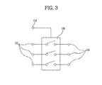
- FIG. 3 is a view showing an embodiment of a relay in FIG. 2
- FIG. 4 is a view showing another embodiment of the relay in FIG. 2 .
- FIG. 5 is an equivalent circuit diagram showing an example of an internal configuration of the relay shown in FIG. 4
- FIG. 6 is an equivalent circuit diagram showing another example of the internal configuration of the relay shown in FIG. 4 .
- the electric bicycle driving apparatus according to the first embodiment of the present invention, denoted by reference numeral 100, is provided at one side and the other side of the electric bicycle, denoted by reference numeral 10.
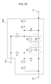
- the electric bicycle driving apparatus 100 includes a speed change mode operator 102, a controller 104, a motor driver 106, a relay 108, and a motor 109.
- the speed change mode operator 102 is provided to output a first speed change mode signal or a second speed change mode signal.
- the speed change mode operator 102 may be provided at a portion of a handlebar of the electric bicycle 10.
- the controller 104 receives the first speed change mode signal or second speed change mode signal output from the speed change mode operator 102 and outputs a first control signal corresponding to the first speed change mode signal or a second control signal corresponding to the second speed change mode signal.
- the controller 104 may include an electronic controller unit (ECU) or a micro controller unit (MCU).
- ECU electronic controller unit
- MCU micro controller unit
- the motor driver 106 receives the first control signal and outputs a first motor driving signal to drive the motor 109 in a low-speed mode corresponding to a first speed change mode. Also, when the speed change mode operator 102 outputs a high-speed mode signal corresponding to the second speed change mode signal, the motor driver 106 receives the second control signal and outputs a second motor driving signal to drive the motor 109, which is rotating with a driving force of the first motor driving signal, in a high-speed mode corresponding to a second speed change mode.
- the motor driver 106 receives the first control signal and outputs the first motor driving signal to drive the motor 109 in the high-speed mode corresponding to the first speed change mode. Also, when the speed change mode operator 102 outputs the low-speed mode signal corresponding to the second speed change mode signal, the motor driver 106 receives the second control signal and outputs the second motor driving signal to drive the motor 109, which is rotating with the driving force of the first motor driving signal, in the low-speed mode corresponding to the second speed change mode.
- the relay 108 selectively receives a relay switching enable signal from the controller 104 so as to be turned on in response to the relay switching enable signal. Upon being turned on, the relay 108 provides at least one of the first motor driving signal and second motor driving signal to the motor 109.
- the relay 108 may be electrically connected between an output stage of the motor driver 106 and an input stage of the motor 109.
- the relay 108 has an internal circuit 108a, which may include a first rectifying diode D1, a first switching device SW1, a first resistor R1, a second rectifying diode D2, a second switching device SW2, and a second resistor R2, as shown in FIGS. 4 and 5 .
- the first rectifying diode D1 may be electrically connected with one side of the controller 104, and the first switching device SW1 may be electrically connected with the first rectifying diode D1 and the motor driver 106.
- the first switching device SW1 may include at least one of a metal-oxide semiconductor field effect transistor (MOSFET) and a bipolar junction transistor (BJT).
- MOSFET metal-oxide semiconductor field effect transistor
- BJT bipolar junction transistor
- the first switching device SW1 may further include at least one Zener diode ZD5 which is electrically connected with the first resistor R1, and the second switching device SW2 to be described later, to cut off an abnormal signal from the motor 109.
- the first resistor R1 may be electrically connected with the first rectifying diode D1, the first switching device SW1 and the motor driver 106, and the second rectifying diode D2 may be electrically connected with the other side of the controller 104.
- the second switching device SW2 may be electrically connected with the second rectifying diode D2, the first switching device SW1 and the motor 109, and the second resistor R2 may be electrically connected with the second rectifying diode D2, the second switching device SW2 and the motor 109.
- the second switching device SW2 may include at least one of a MOSFET and a BJT.
- the second switching device SW2 may further include at least one Zener diode ZD6 which is electrically connected with the first switching device SW1 and the second resistor R2 to cut off an abnormal signal from the motor driver 106.
- the relay 108 when the first and second switching devices SW1 and SW2 are turned on in response to the relay switching enable signal from the controller 104, rectified through the first and second rectifying diodes D1 and D2, the level of the first motor driving signal or second motor driving signal supplied from the motor driver 106 is adjusted by the first resistor R1 and in turn by the second resistor R2, and the first motor driving signal or second motor driving signal of the adjusted level is then supplied to the motor 109.
- the internal circuit 108a of the relay 108 may further include one or more Zener diodes ZD1 and ZD2 which are electrically connected with the motor driver 106 and the first resistor R1 to cut off an abnormal signal from the motor driver 106.
- the internal circuit 108a of the relay 108 may further include one or more Zener diodes ZD3 and ZD4 which are electrically connected with the second resistor R2 and the motor 109 to cut off an abnormal signal from the motor 109.
- the internal circuit 108a of the relay 108 may include a third rectifying diode D3, a third switching device SW3, a third resistor R3, and a fourth switching device SW4.
- the third rectifying diode D3 may be electrically connected with one side of the controller 104, and the third switching device SW3 may be electrically connected with the third rectifying diode D3 and the motor driver 106.
- the third switching device SW3 may include at least one of a MOSFET and a BJT.
- the third switching device SW3 may further include at least one Zener diode ZD9 which is electrically connected with the motor driver 106 and the third resistor R3 to cut off an abnormal signal from the motor 109.
- the third resistor R3 may be electrically connected with the third rectifying diode D3 and the third switching device SW3, and the fourth switching device SW4 may be electrically connected with the third rectifying diode D3, the third resistor R3 and the motor 109.
- the fourth switching device SW4 may include at least one of a MOSFET and a BJT.
- the fourth switching device SW4 may further include at least one Zener diode ZD10 which is electrically connected with the third resistor R3 and the motor 109 to cut off an abnormal signal from the motor driver 106.
- the internal circuit 108a of the relay 108 may further include one or more Zener diodes ZD7 and ZD8 which are electrically connected with the third resistor R3, the third rectifying diode D3 and the fourth switching device SW4 to cut off an abnormal signal from at least one of the motor driver 106 and motor 109.
- the electric bicycle driving apparatus 100 includes the speed change mode operator 102, the controller 104, the motor driver 106, the relay 108, and the motor 109.
- the electric bicycle driving apparatus 100 when the first motor driving signal or second motor driving signal, output from the motor driver 106 for the speed change mode, is supplied to the motor 109, it may be possible to provide a faster switching response characteristic for a turn-on operation, thereby rapidly reducing a speed change mode time.
- the electric bicycle driving apparatus 100 when the first motor driving signal or second motor driving signal, output from the motor driver 106 for the speed change mode, is supplied to the motor 109, it may be possible to reduce heat generation to prevent malfunction.
- the unified relay 108 is employed, thereby making it possible to suppress an increase in cost of parts manufactured for the speed change mode.
- FIG. 7 is a block diagram showing the configuration of an electric bicycle driving apparatus according to a second embodiment of the present invention
- FIG. 8 is a view showing an embodiment of a relay in FIG. 7
- FIG. 9 is a view showing another embodiment of the relay in FIG. 7 .
- FIG. 10 is an equivalent circuit diagram showing an example of an internal configuration of the relay shown in FIG. 9
- FIG. 11 is an equivalent circuit diagram showing another example of the internal configuration of the relay shown in FIG. 9 .
- FIG. 12 is an equivalent circuit diagram showing another example of the internal configuration of the relay shown in FIG. 9
- FIG. 13 is an equivalent circuit diagram showing another example of the internal configuration of the relay shown in FIG. 9 .
- the electric bicycle driving apparatus includes a speed change mode operator 102, a controller 104, a motor driver 106, a relay 708, and a motor 109.
- the speed change mode operator 102 is provided to output a first speed change mode signal or a second speed change mode signal.
- the speed change mode operator 102 may be provided at a portion of a handlebar of the electric bicycle 10.
- the controller 104 receives the first speed change mode signal or second speed change mode signal output from the speed change mode operator 102 and outputs a first control signal corresponding to the first speed change mode signal or a second control signal corresponding to the second speed change mode signal.
- the controller 104 may include an electronic controller unit (ECU) or a micro controller unit (MCU).
- ECU electronic controller unit
- MCU micro controller unit
- the motor driver 106 receives the first control signal and outputs a first motor driving signal to drive the motor 109 in a low-speed mode corresponding to a first speed change mode. Also, when the speed change mode operator 102 outputs a high-speed mode signal corresponding to the second speed change mode signal, the motor driver 106 receives the second control signal and outputs a second motor driving signal to drive the motor 109, which is rotating with a driving force of the first motor driving signal, in a high-speed mode corresponding to a second speed change mode.
- the motor driver 106 receives the first control signal and outputs the first motor driving signal to drive the motor 109 in the high-speed mode corresponding to the first speed change mode. Also, when the speed change mode operator 102 outputs the low-speed mode signal corresponding to the second speed change mode signal, the motor driver 106 receives the second control signal and outputs the second motor driving signal to drive the motor 109, which is rotating with the driving force of the first motor driving signal, in the low-speed mode corresponding to the second speed change mode.
- the relay 708 selectively receives a relay switching enable signal from the controller 104 so as to be turned on in response to the relay switching enable signal. Upon being turned on, the relay 708 provides the first motor driving signal and the second motor driving signal to the motor 109.
- the relay 708 includes a first relay 708a to provide the first motor driving signal output from the motor driver 106 to the motor 109, and a second relay 708b to provide the second motor driving signal output from the motor driver 106 to the motor 109.
- the first relay 708a and the second relay 708b may be electrically connected between an output stage of the motor driver 106 and an input stage of the motor 109.
- the first relay 708a selectively receives a first relay switching enable signal of the relay switching enable signal so as to be turned on in response to the first relay switching enable signal. Upon being turned on, the first relay 708a supplies the first motor driving signal to the motor 109. Also, the second relay 708b selectively receives a second relay switching enable signal of the relay switching enable signal so as to be turned on in response to the second relay switching enable signal. Upon being turned on, the second relay 708b supplies the second motor driving signal to the motor 109.
- the first relay 708a and the second relay 708b have internal circuits 708a1 and 708b1, respectively, each of which may include a first rectifying diode D1, a first switching device SW1, a first resistor R1, a second rectifying diode D2, a second switching device SW2, and a second resistor R2.
- the first rectifying diode D1 may be electrically connected with one side of the controller 104, and the first switching device SW1 may be electrically connected with the first rectifying diode D1 and the motor driver 106.
- the first switching device SW1 may include at least one of a metal-oxide semiconductor field effect transistor (MOSFET) and a bipolar junction transistor (BJT).
- MOSFET metal-oxide semiconductor field effect transistor
- BJT bipolar junction transistor
- the first switching device SW1 may further include at least one Zener diode ZD5 which is electrically connected with the first resistor R1, and the second switching device SW2 to be described later, to cut off an abnormal signal from the motor 109.
- the first resistor R1 may be electrically connected with the first rectifying diode D1, the first switching device SW1 and the motor driver 106, and the second rectifying diode D2 may be electrically connected with the other side of the controller 104.
- the second switching device SW2 may be electrically connected with the second rectifying diode D2, the first switching device SW1 and the motor 109, and the second resistor R2 may be electrically connected with the second rectifying diode D2, the second switching device SW2 and the motor 109.
- the second switching device SW2 may include at least one of a MOSFET and a BJT.
- the second switching device SW2 may further include at least one Zener diode ZD6 which is electrically connected with the first switching device SW1 and the second resistor R2 to cut off an abnormal signal from the motor driver 106.
- first relay 708a and second relay 708b With the above configuration, when the first and second switching devices SW1 and SW2 are turned on in response to the relay switching enable signal from the controller 104, rectified through the first and second rectifying diodes D1 and D2, the level of the first motor driving signal or second motor driving signal supplied from the motor driver 106 is adjusted by the first resistor R1 and in turn by the second resistor R2, and the first motor driving signal or second motor driving signal of the adjusted level is then supplied to the motor 109.
- each of the internal circuits 708a1 and 708b1 of the first relay 708a and second relay 708b may further include one or more Zener diodes ZD1 and ZD2 which are electrically connected with the motor driver 106 and the first resistor R1 to cut off an abnormal signal from the motor driver 106.
- each of the internal circuits 708a1 and 708b1 of the first relay 708a and second relay 708b may further include one or more Zener diodes ZD3 and ZD4 which are electrically connected with the second resistor R2 and the motor 109 to cut off an abnormal signal from the motor 109.
- the first relay 708a selectively receives the first relay switching enable signal of the relay switching enable signal so as to be turned on in response to the first relay switching enable signal. Upon being turned on, the first relay 708a supplies the first motor driving signal to the motor 109. Also, the second relay 708b selectively receives the second relay switching enable signal of the relay switching enable signal so as to be turned on in response to the second relay switching enable signal. Upon being turned on, the second relay 708b supplies the second motor driving signal to the motor 109.
- Each of the internal circuits 708a1 and 708b1 of the first relay 708a and second relay 708b may include a third rectifying diode D3, a third switching device SW3, a third resistor R3, and a fourth switching device SW4.
- the third rectifying diode D3 may be electrically connected with one side of the controller 104, and the third switching device SW3 may be electrically connected with the third rectifying diode D3 and the motor driver 106.
- the third switching device SW3 may include at least one of a MOSFET and a BJT.
- the third switching device SW3 may further include at least one Zener diode ZD9 which is electrically connected with the motor driver 106 and the third resistor R3 to cut off an abnormal signal from the motor 109.
- the third resistor R3 may be electrically connected with the third rectifying diode D3 and the third switching device SW3, and the fourth switching device SW4 may be electrically connected with the third rectifying diode D3, the third resistor R3 and the motor 109.
- the fourth switching device SW4 may include at least one of a MOSFET and a BJT.
- the fourth switching device SW4 may further include at least one Zener diode ZD10 which is electrically connected with the third resistor R3 and the motor 109 to cut off an abnormal signal from the motor driver 106.
- each of the internal circuits 708a1 and 708b1 of the first relay 708a and second relay 708b may further include one or more Zener diodes ZD7 and ZD8 which are electrically connected with the third resistor R3, the third rectifying diode D3 and the fourth switching device SW4 to cut off an abnormal signal from at least one of the motor driver 106 and motor 109.
- the electric bicycle driving apparatus 700 includes the speed change mode operator 102, the controller 104, the motor driver 106, the relay 708, and the motor 109.
- the electric bicycle driving apparatus 700 when the first motor driving signal or second motor driving signal, output from the motor driver 106 for the speed change mode, is supplied to the motor 109, it may be possible to provide a faster switching response characteristic for a turn-on operation, thereby rapidly reducing a speed change mode time.
- the electric bicycle driving apparatus 700 when the first motor driving signal or second motor driving signal, output from the motor driver 106 for the speed change mode, is supplied to the motor 109, it may be possible to reduce heat generation to prevent malfunction.
- the load to be driven is reduced, thereby reducing consumption of battery power.
- the first relay 708a and the second relay 708b are employed. Therefore, when the first motor driving signal or second motor driving signal, output from the motor driver 106 for the speed change mode, is supplied to the motor 109, each of the first relay 708a and second relay 708b may provide a faster switching response characteristic for a turn-on operation, thereby more rapidly reducing a speed change mode time.
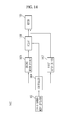
- FIG. 14 is a block diagram showing the configuration of an electric bicycle driving apparatus according to a third embodiment of the present invention
- FIG. 15 is a view showing an embodiment of a relay in FIG. 14
- FIG. 16 is a view showing another embodiment of the relay in FIG. 14 .
- FIG. 17 is an equivalent circuit diagram showing an example of an internal configuration of the relay shown in FIG. 16
- FIG. 18 is an equivalent circuit diagram showing another example of the internal configuration of the relay shown in FIG. 16 .
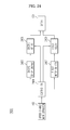
- the electric bicycle driving apparatus includes a speed change mode operator 102, a controller 1404, a first motor driver 1407, a second motor driver 1406, a relay 1408, and a motor 109.
- the speed change mode operator 102 is provided to output a first speed change mode signal or a second speed change mode signal.
- the speed change mode operator 102 may be provided at a portion of a handlebar of the electric bicycle 10.
- the controller 1404 receives the first speed change mode signal or second speed change mode signal output from the speed change mode operator 102 and outputs a first control signal corresponding to the first speed change mode signal or a second control signal corresponding to the second speed change mode signal.
- the controller 1404 may include an electronic controller unit (ECU) or a micro controller unit (MCU).
- ECU electronic controller unit
- MCU micro controller unit
- the first motor driver 1407 receives the first control signal and outputs a first motor driving signal to drive the motor 109 in a low-speed mode corresponding to a first speed change mode. Also, when the speed change mode operator 102 outputs a high-speed mode signal corresponding to the second speed change mode signal, the second motor driver 1406 receives the second control signal and outputs a second motor driving signal to drive the motor 109, which is rotating with a driving force of the first motor driving signal, in a high-speed mode corresponding to a second speed change mode.
- the second motor driver 1406 receives the first control signal and outputs the first motor driving signal to drive the motor 109 in the high-speed mode corresponding to the first speed change mode. Also, when the speed change mode operator 102 outputs the low-speed mode signal corresponding to the second speed change mode signal, the first motor driver 1407 receives the second control signal and outputs the second motor driving signal to drive the motor 109, which is rotating with the driving force of the first motor driving signal, in the low-speed mode corresponding to the second speed change mode.
- the relay 1408 selectively receives a relay switching enable signal from the controller 1404 so as to be turned on in response to the relay switching enable signal. Upon being turned on, the relay 1408 provides at least one of the first motor driving signal and second motor driving signal to the motor 109.
- the relay 1408 may be electrically connected between an output stage of the second motor driver 1406 and an input stage of the motor 109.
- the relay 1408 has an internal circuit 1408a, which may include a first rectifying diode D1, a first switching device SW1, a first resistor R1, a second rectifying diode D2, a second switching device SW2, and a second resistor R2, as shown in FIGS. 16 and 17 .
- the first rectifying diode D1 may be electrically connected with one side of the controller 1404, and the first switching device SW1 may be electrically connected with the first rectifying diode D1 and the second motor driver 1406.
- the first switching device SW1 may include at least one of a metal-oxide semiconductor field effect transistor (MOSFET) and a bipolar junction transistor (BJT).
- MOSFET metal-oxide semiconductor field effect transistor
- BJT bipolar junction transistor
- the first switching device SW1 may further include at least one Zener diode ZD5 which is electrically connected with the first resistor R1, and the second switching device SW2 to be described later, to cut off an abnormal signal from the motor 109.
- the first resistor R1 may be electrically connected with the first rectifying diode D1, the first switching device SW1 and the second motor driver 1406, and the second rectifying diode D2 may be electrically connected with the other side of the controller 1404.
- the second switching device SW2 may be electrically connected with the second rectifying diode D2, the first switching device SW1 and the motor 109, and the second resistor R2 may be electrically connected with the second rectifying diode D2, the second switching device SW2 and the motor 109.
- the second switching device SW2 may include at least one of a MOSFET and a BJT.
- the second switching device SW2 may further include at least one Zener diode ZD6 which is electrically connected with the first switching device SW1 and the second resistor R2 to cut off an abnormal signal from the second motor driver 1406.
- the relay 1408 when the first and second switching devices SW1 and SW2 are turned on in response to the relay switching enable signal from the controller 1404, rectified through the first and second rectifying diodes D1 and D2, the level of the first motor driving signal or second motor driving signal supplied from the second motor driver 1406 is adjusted by the first resistor R1 and in turn by the second resistor R2, and the first motor driving signal or second motor driving signal of the adjusted level is then supplied to the motor 109.
- the internal circuit 1408a of the relay 1408 may further include one or more Zener diodes ZD1 and ZD2 which are electrically connected with the second motor driver 1406 and the first resistor R1 to cut off an abnormal signal from the second motor driver 1406.
- the internal circuit 1408a of the relay 1408 may further include one or more Zener diodes ZD3 and ZD4 which are electrically connected with the second resistor R2 and the motor 109 to cut off an abnormal signal from the motor 109.
- the internal circuit 1408a of the relay 1408 may include a third rectifying diode D3, a third switching device SW3, a third resistor R3, and a fourth switching device SW4.
- the third rectifying diode D3 may be electrically connected with one side of the controller 1404, and the third switching device SW3 may be electrically connected with the third rectifying diode D3 and the second motor driver 1406.
- the third switching device SW3 may include at least one of a MOSFET and a BJT.
- the third switching device SW3 may further include at least one Zener diode ZD9 which is electrically connected with the second motor driver 1406 and the third resistor R3 to cut off an abnormal signal from the motor 109.
- the third resistor R3 may be electrically connected with the third rectifying diode D3 and the third switching device SW3, and the fourth switching device SW4 may be electrically connected with the third rectifying diode D3, the third resistor R3 and the motor 109.
- the fourth switching device SW4 may include at least one of a MOSFET and a BJT.
- the fourth switching device SW4 may further include at least one Zener diode ZD10 which is electrically connected with the third resistor R3 and the motor 109 to cut off an abnormal signal from the second motor driver 1406.
- the internal circuit 1408a of the relay 1408 may further include one or more Zener diodes ZD7 and ZD8 which are electrically connected with the third resistor R3, the third rectifying diode D3 and the fourth switching device SW4 to cut off an abnormal signal from at least one of the second motor driver 1406 and motor 109.
- the electric bicycle driving apparatus 1400 includes the speed change mode operator 102, the controller 1404, the first motor driver 1407, the second motor driver 1406, the relay 1408, and the motor 109.
- the electric bicycle driving apparatus 1400 when the first motor driving signal or second motor driving signal, output from the first motor driver 1407 or second motor driver 1406 for the speed change mode, is supplied to the motor 109, it may be possible to provide a faster switching response characteristic for a turn-on operation, thereby rapidly reducing a speed change mode time.
- the electric bicycle driving apparatus 1400 when the first motor driving signal or second motor driving signal, output from the first motor driver 1407 or second motor driver 1406 for the speed change mode, is supplied to the motor 109, it may be possible to reduce heat generation to prevent malfunction.
- the load to be driven is reduced still further, thereby reducing consumption of battery power still further.
- the unified relay 1408 is employed, thereby making it possible to suppress an increase in cost of parts manufactured for the speed change mode.
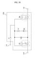
- FIG. 19 is a block diagram showing the configuration of an electric bicycle driving apparatus according to a fourth embodiment of the present invention
- FIG. 20 is a view showing an embodiment of a relay in FIG. 19
- FIG. 21 is a view showing another embodiment of the relay in FIG. 19 .
- FIG. 22 is an equivalent circuit diagram showing an example of an internal configuration of the relay shown in FIG. 21
- FIG. 23 is an equivalent circuit diagram showing another example of the internal configuration of the relay shown in FIG. 21 .
- the electric bicycle driving apparatus includes a speed change mode operator 102, a controller 1904, a first motor driver 1907, a second motor driver 1906, a relay 1908, and a motor 109.
- the speed change mode operator 102 is provided to output a first speed change mode signal or a second speed change mode signal.
- the speed change mode operator 102 may be provided at a portion of a handlebar of the electric bicycle 10.
- the controller 1904 receives the first speed change mode signal or second speed change mode signal output from the speed change mode operator 102 and outputs a first control signal corresponding to the first speed change mode signal or a second control signal corresponding to the second speed change mode signal.
- the controller 1904 may include an electronic controller unit (ECU) or a micro controller unit (MCU).
- ECU electronic controller unit
- MCU micro controller unit
- the first motor driver 1907 receives the first control signal and outputs a first motor driving signal to drive the motor 109 in a low-speed mode corresponding to a first speed change mode. Also, when the speed change mode operator 102 outputs a high-speed mode signal corresponding to the second speed change mode signal, the second motor driver 1906 receives the second control signal and outputs a second motor driving signal to drive the motor 109, which is rotating with a driving force of the first motor driving signal, in a high-speed mode corresponding to a second speed change mode.
- the second motor driver 1906 receives the first control signal and outputs the first motor driving signal to drive the motor 109 in the high-speed mode corresponding to the first speed change mode. Also, when the speed change mode operator 102 outputs the low-speed mode signal corresponding to the second speed change mode signal, the first motor driver 1907 receives the second control signal and outputs the second motor driving signal to drive the motor 109, which is rotating with the driving force of the first motor driving signal, in the low-speed mode corresponding to the second speed change mode.
- the relay 1908 selectively receives a relay switching enable signal from the controller 1904 so as to be turned on in response to the relay switching enable signal. Upon being turned on, the relay 1908 provides at least one of the first motor driving signal and second motor driving signal to the motor 109.
- the relay 1908 may be electrically connected between an output stage of the first motor driver 1907 and an input stage of the motor 109.
- the relay 1908 has an internal circuit 1908a, which may include a first rectifying diode D1, a first switching device SW1, a first resistor R1, a second rectifying diode D2, a second switching device SW2, and a second resistor R2, as shown in FIGS. 21 and 22 .
- the first rectifying diode D1 may be electrically connected with one side of the controller 1904, and the first switching device SW1 may be electrically connected with the first rectifying diode D1 and the first motor driver 1907.
- the first switching device SW1 may include at least one of a metal-oxide semiconductor field effect transistor (MOSFET) and a bipolar junction transistor (BJT).
- MOSFET metal-oxide semiconductor field effect transistor
- BJT bipolar junction transistor
- the first switching device SW1 may further include at least one Zener diode ZD5 which is electrically connected with the first resistor R1, and the second switching device SW2 to be described later, to cut off an abnormal signal from the motor 109.
- the first resistor R1 may be electrically connected with the first rectifying diode D1, the first switching device SW1 and the first motor driver 1907, and the second rectifying diode D2 may be electrically connected with the other side of the controller 1904.
- the second switching device SW2 may be electrically connected with the second rectifying diode D2, the first switching device SW1 and the motor 109, and the second resistor R2 may be electrically connected with the second rectifying diode D2, the second switching device SW2 and the motor 109.
- the second switching device SW2 may include at least one of a MOSFET and a BJT.
- the second switching device SW2 may further include at least one Zener diode ZD6 which is electrically connected with the first switching device SW1 and the second resistor R2 to cut off an abnormal signal from the first motor driver 1907.
- the relay 1908 when the first and second switching devices SW1 and SW2 are turned on in response to the relay switching enable signal from the controller 1904, rectified through the first and second rectifying diodes D1 and D2, the level of the first motor driving signal or second motor driving signal supplied from the first motor driver 1907 is adjusted by the first resistor R1 and in turn by the second resistor R2, and the first motor driving signal or second motor driving signal of the adjusted level is then supplied to the motor 109.
- the internal circuit 1908a of the relay 1908 may further include one or more Zener diodes ZD1 and ZD2 which are electrically connected with the first motor driver 1907 and the first resistor R1 to cut off an abnormal signal from the first motor driver 1907.
- the internal circuit 1908a of the relay 1908 may further include one or more Zener diodes ZD3 and ZD4 which are electrically connected with the second resistor R2 and the motor 109 to cut off an abnormal signal from the motor 109.
- the internal circuit 1908a of the relay 1908 may include a third rectifying diode D3, a third switching device SW3, a third resistor R3, and a fourth switching device SW4.
- the third rectifying diode D3 may be electrically connected with one side of the controller 1904, and the third switching device SW3 may be electrically connected with the third rectifying diode D3 and the first motor driver 1907.
- the third switching device SW3 may include at least one of a MOSFET and a BJT.
- the third switching device SW3 may further include at least one Zener diode ZD9 which is electrically connected with the first motor driver 1907 and the third resistor R3 to cut off an abnormal signal from the motor 109.
- the third resistor R3 may be electrically connected with the third rectifying diode D3 and the third switching device SW3, and the fourth switching device SW4 may be electrically connected with the third rectifying diode D3, the third resistor R3 and the motor 109.
- the fourth switching device SW4 may include at least one of a MOSFET and a BJT.
- the fourth switching device SW4 may further include at least one Zener diode ZD10 which is electrically connected with the third resistor R3 and the motor 109 to cut off an abnormal signal from the first motor driver 1907.
- the internal circuit 1908a of the relay 1908 may further include one or more Zener diodes ZD7 and ZD8 which are electrically connected with the third resistor R3, the third rectifying diode D3 and the fourth switching device SW4 to cut off an abnormal signal from at least one of the first motor driver 1907 and motor 109.
- the electric bicycle driving apparatus 1900 includes the speed change mode operator 102, the controller 1904, the first motor driver 1907, the second motor driver 1906, the relay 1908, and the motor 109.
- the electric bicycle driving apparatus 1900 when the first motor driving signal or second motor driving signal, output from the first motor driver 1907 or second motor driver 1906 for the speed change mode, is supplied to the motor 109, it may be possible to provide a faster switching response characteristic for a turn-on operation, thereby rapidly reducing a speed change mode time.
- the electric bicycle driving apparatus 1900 when the first motor driving signal or second motor driving signal, output from the first motor driver 1907 or second motor driver 1906 for the speed change mode, is supplied to the motor 109, it may be possible to reduce heat generation to prevent malfunction.
- the load to be driven is reduced still further, thereby reducing consumption of battery power still further.
- the unified relay 1908 is employed, thereby making it possible to suppress an increase in cost of parts manufactured for the speed change mode.
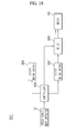
- FIG. 24 is a block diagram showing the configuration of an electric bicycle driving apparatus according to a fifth embodiment of the present invention
- FIG. 25 is a view showing an embodiment of a relay connected to a second motor driver, shown in FIG. 24
- FIG. 26 is a view showing another embodiment of the relay connected to the second motor driver, shown in FIG. 24 .
- FIG. 27 is an equivalent circuit diagram showing an example of an internal configuration of the relay shown in FIG. 26
- FIG. 28 is an equivalent circuit diagram showing another example of the internal configuration of the relay shown in FIG. 26 .
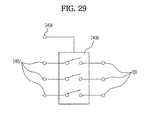
- FIG. 29 is a view showing an embodiment of a relay connected to a first motor driver, shown in FIG. 24
- FIG. 30 is a view showing another embodiment of the relay connected to the first motor driver, shown in FIG. 24 .
- FIG. 31 is an equivalent circuit diagram showing an example of an internal configuration of the relay shown in FIG. 30
- FIG. 32 is an equivalent circuit diagram showing another example of the internal configuration of the relay shown in FIG. 30 .
- the electric bicycle driving apparatus includes a speed change mode operator 102, a controller 2404, a first motor driver 2407, a second motor driver 2406, first and second relays 2409 and 2408, and a motor 109.
- the speed change mode operator 102 is provided to output a first speed change mode signal or a second speed change mode signal.
- the speed change mode operator 102 may be provided at a portion of a handlebar of the electric bicycle 10.
- the controller 2404 receives the first speed change mode signal or second speed change mode signal output from the speed change mode operator 102 and outputs a first control signal corresponding to the first speed change mode signal or a second control signal corresponding to the second speed change mode signal.
- the controller 2404 may include an electronic controller unit (ECU) or a micro controller unit (MCU).
- ECU electronic controller unit
- MCU micro controller unit
- the first motor driver 2407 receives the first control signal and outputs a first motor driving signal to drive the motor 109 in a low-speed mode corresponding to a first speed change mode. Also, when the speed change mode operator 102 outputs a high-speed mode signal corresponding to the second speed change mode signal, the second motor driver 2406 receives the second control signal and outputs a second motor driving signal to drive the motor 109, which is rotating with a driving force of the first motor driving signal, in a high-speed mode corresponding to a second speed change mode.
- the second motor driver 2406 receives the first control signal and outputs the first motor driving signal to drive the motor 109 in the high-speed mode corresponding to the first speed change mode. Also, when the speed change mode operator 102 outputs the low-speed mode signal corresponding to the second speed change mode signal, the first motor driver 2407 receives the second control signal and outputs the second motor driving signal to drive the motor 109, which is rotating with the driving force of the first motor driving signal, in the low-speed mode corresponding to the second speed change mode.
- the first and second relays 2409 and 2408 selectively receive a relay switching enable signal from the controller 2404 so as to be turned on in response to the relay switching enable signal. Upon being turned on, the first and second relays 2409 and 2408 provide the first motor driving signal and the second motor driving signal to the motor 109.
- the first relay 2409 provides the first motor driving signal output from the first motor driver 2407 to the motor 109
- the second relay 2408 provides the second motor driving signal output from the second motor driver 2406 to the motor 109.
- the second relay 2408 may be electrically connected between an output stage of the second motor driver 2406 and an input stage of the motor 109.
- the second relay 2408 selectively receives a second relay switching enable signal of the relay switching enable signal so as to be turned on in response to the second relay switching enable signal. Upon being turned on, the second relay 2408 supplies the second motor driving signal to the motor 109.
- the second relay 2408 has an internal circuit 2408a, which may include a first rectifying diode D1, a first switching device SW1, a first resistor R1, a second rectifying diode D2, a second switching device SW2, and a second resistor R2.
- the first rectifying diode D1 may be electrically connected with one side of the controller 2404, and the first switching device SW1 may be electrically connected with the first rectifying diode D1 and the second motor driver 2406.
- the first switching device SW1 may include at least one of a metal-oxide semiconductor field effect transistor (MOSFET) and a bipolar junction transistor (BJT).
- MOSFET metal-oxide semiconductor field effect transistor
- BJT bipolar junction transistor
- the first switching device SW1 may further include at least one Zener diode ZD5 which is electrically connected with the first resistor R1, and the second switching device SW2 to be described later, to cut off an abnormal signal from the motor 109.
- the first resistor R1 may be electrically connected with the first rectifying diode D1, the first switching device SW1 and the second motor driver 2406, and the second rectifying diode D2 may be electrically connected with the other side of the controller 2404.
- the second switching device SW2 may be electrically connected with the second rectifying diode D2, the first switching device SW1 and the motor 109, and the second resistor R2 may be electrically connected with the second rectifying diode D2, the second switching device SW2 and the motor 109.
- the second switching device SW2 may include at least one of a MOSFET and a BJT.
- the second switching device SW2 may further include at least one Zener diode ZD6 which is electrically connected with the first switching device SW1 and the second resistor R2 to cut off an abnormal signal from the second motor driver 2406.
- the second relay 2408 when the first and second switching devices SW1 and SW2 are turned on in response to the relay switching enable signal from the controller 2404, rectified through the first and second rectifying diodes D1 and D2, the level of the first motor driving signal or second motor driving signal supplied from the second motor driver 2406 is adjusted by the first resistor R1 and in turn by the second resistor R2, and the first motor driving signal or second motor driving signal of the adjusted level is then supplied to the motor 109.
- the internal circuit 2408a of the second relay 2408 may further include one or more Zener diodes ZD1 and ZD2 which are electrically connected with the second motor driver 2406 and the first resistor R1 to cut off an abnormal signal from the second motor driver 2406.
- the internal circuit 2408a of the second relay 2408 may further include one or more Zener diodes ZD3 and ZD4 which are electrically connected with the second resistor R2 and the motor 109 to cut off an abnormal signal from the motor 109.
- the second relay 2408 selectively receives the second relay switching enable signal of the relay switching enable signal so as to be turned on in response to the second relay switching enable signal. Upon being turned on, the second relay 2408 supplies the second motor driving signal to the motor 109.
- the internal circuit 2408a of the second relay 2408 may include a third rectifying diode D3, a third switching device SW3, a third resistor R3, and a fourth switching device SW4.
- the third rectifying diode D3 may be electrically connected with one side of the controller 2404, and the third switching device SW3 may be electrically connected with the third rectifying diode D3 and the second motor driver 2406.
- the third switching device SW3 may include at least one of a MOSFET and a BJT.
- the third switching device SW3 may further include at least one Zener diode ZD9 which is electrically connected with the second motor driver 2406 and the third resistor R3 to cut off an abnormal signal from the motor 109.
- the third resistor R3 may be electrically connected with the third rectifying diode D3 and the third switching device SW3, and the fourth switching device SW4 may be electrically connected with the third rectifying diode D3, the third resistor R3 and the motor 109.
- the fourth switching device SW4 may include at least one of a MOSFET and a BJT.
- the fourth switching device SW4 may further include at least one Zener diode ZD10 which is electrically connected with the third resistor R3 and the motor 109 to cut off an abnormal signal from the second motor driver 2406.
- the internal circuit 2408a of the second relay 2408 may further include one or more Zener diodes ZD7 and ZD8 which are electrically connected with the third resistor R3, the third rectifying diode D3 and the fourth switching device SW4 to cut off an abnormal signal from at least one of the second motor driver 2406 and motor 109.
- the first relay 2409 may be electrically connected between an output stage of the first motor driver 2407 and the input stage of the motor 109, as shown in FIGS. 29 to 32 .
- the first relay 2409 selectively receives a first relay switching enable signal of the relay switching enable signal so as to be turned on in response to the first relay switching enable signal. Upon being turned on, the first relay 2409 supplies the first motor driving signal to the motor 109.
- the first relay 2409 has an internal circuit 2409a, which may include a first rectifying diode D1, a first switching device SW1, a first resistor R1, a second rectifying diode D2, a second switching device SW2, and a second resistor R2.
- the first rectifying diode D1 may be electrically connected with one side of the controller 2404, and the first switching device SW1 may be electrically connected with the first rectifying diode D1 and the first motor driver 2407.
- the first switching device SW1 may include at least one of a metal-oxide semiconductor field effect transistor (MOSFET) and a bipolar junction transistor (BJT).
- MOSFET metal-oxide semiconductor field effect transistor
- BJT bipolar junction transistor
- the first switching device SW1 may further include at least one Zener diode ZD5 which is electrically connected with the first resistor R1, and the second switching device SW2 to be described later, to cut off an abnormal signal from the motor 109.
- the first resistor R1 may be electrically connected with the first rectifying diode D1, the first switching device SW1 and the first motor driver 2407, and the second rectifying diode D2 may be electrically connected with the other side of the controller 2404.
- the second switching device SW2 may be electrically connected with the second rectifying diode D2, the first switching device SW1 and the motor 109, and the second resistor R2 may be electrically connected with the second rectifying diode D2, the second switching device SW2 and the motor 109.
- the second switching device SW2 may include at least one of a MOSFET and a BJT.
- the second switching device SW2 may further include at least one Zener diode ZD6 which is electrically connected with the first switching device SW1 and the second resistor R2 to cut off an abnormal signal from the first motor driver 2407.
- the first relay 2409 when the first and second switching devices SW1 and SW2 are turned on in response to the relay switching enable signal from the controller 2404, rectified through the first and second rectifying diodes D1 and D2, the level of the first motor driving signal or first motor driving signal supplied from the first motor driver 2407 is adjusted by the first resistor R1 and in turn by the second resistor R2, and the first motor driving signal or first motor driving signal of the adjusted level is then supplied to the motor 109.
- the internal circuit 2409a of the first relay 2409 may further include one or more Zener diodes ZD1 and ZD2 which are electrically connected with the first motor driver 2407 and the first resistor R1 to cut off an abnormal signal from the first motor driver 2407.
- the internal circuit 2409a of the first relay 2409 may further include one or more Zener diodes ZD3 and ZD4 which are electrically connected with the second resistor R2 and the motor 109 to cut off an abnormal signal from the motor 109.
- the first relay 2409 selectively receives the first relay switching enable signal of the relay switching enable signal so as to be turned on in response to the first relay switching enable signal. Upon being turned on, the first relay 2409 supplies the first motor driving signal to the motor 109.
- the internal circuit 2409a of the first relay 2409 may include a third rectifying diode D3, a third switching device SW3, a third resistor R3, and a fourth switching device SW4.
- the third rectifying diode D3 may be electrically connected with one side of the controller 2404, and the third switching device SW3 may be electrically connected with the third rectifying diode D3 and the first motor driver 2407.
- the third switching device SW3 may include at least one of a MOSFET and a BJT.
- the third switching device SW3 may further include at least one Zener diode ZD9 which is electrically connected with the first motor driver 2407 and the third resistor R3 to cut off an abnormal signal from the motor 109.
- the third resistor R3 may be electrically connected with the third rectifying diode D3 and the third switching device SW3, and the fourth switching device SW4 may be electrically connected with the third rectifying diode D3, the third resistor R3 and the motor 109.
- the fourth switching device SW4 may include at least one of a MOSFET and a BJT.
- the fourth switching device SW4 may further include at least one Zener diode ZD10 which is electrically connected with the third resistor R3 and the motor 109 to cut off an abnormal signal from the first motor driver 2407.
- the internal circuit 2409a of the first relay 2409 may further include one or more Zener diodes ZD7 and ZD8 which are electrically connected with the third resistor R3, the third rectifying diode D3 and the fourth switching device SW4 to cut off an abnormal signal from at least one of the first motor driver 2407 and motor 109.
- the electric bicycle driving apparatus 2400 includes the speed change mode operator 102, the controller 2404, the first motor driver 2407, the second motor driver 2406, the first relay 2409, the second relay 2408, and the motor 109.
- the electric bicycle driving apparatus 2400 when the first motor driving signal or second motor driving signal, output from the first motor driver 2407 or second motor driver 2406 for the speed change mode, is supplied to the motor 109, it may be possible to provide a faster switching response characteristic for a turn-on operation, thereby rapidly reducing a speed change mode time.
- the electric bicycle driving apparatus 2400 when the first motor driving signal or second motor driving signal, output from the first motor driver 2407 or second motor driver 2406 for the speed change mode, is supplied to the motor 109, it may be possible to reduce heat generation to prevent malfunction.
- the load to be driven is reduced, thereby reducing consumption of battery power.
- the first relay 2409 and the second relay 2408 are employed. Therefore, when the first motor driving signal or second motor driving signal, output from the first motor driver 2407 or second motor driver 2406 for the speed change mode, is supplied to the motor 109, each of the first relay 2409 and second relay 2408 may provide a faster switching response characteristic for a turn-on operation, thereby more rapidly reducing a speed change mode time.
Landscapes
- Engineering & Computer Science (AREA)
- Mechanical Engineering (AREA)
- Transportation (AREA)
- Power Engineering (AREA)
- Chemical & Material Sciences (AREA)
- Combustion & Propulsion (AREA)
- Life Sciences & Earth Sciences (AREA)
- Sustainable Development (AREA)
- Sustainable Energy (AREA)
- Control Of Electric Motors In General (AREA)
- Electric Propulsion And Braking For Vehicles (AREA)
- Control Of Multiple Motors (AREA)
Abstract
Description
- Embodiments of the present invention relate to an electric bicycle driving apparatus.
- In general, electric bicycle driving apparatuses are provided to drive electric bicycles.
- Such a conventional electric bicycle driving apparatus reduces a speed change mode time by shortening a driving time of a motor driver when driving a motor of an electric bicycle in a high-speed mode or low-speed mode. To this end, the conventional electric bicycle driving apparatus includes a high-speed mode switching circuit and a low-speed mode switching circuit employing separate rectifying diodes and semiconductor switching devices.
- However, in the conventional electric bicycle driving apparatus, heat may be generated from the rectifying diodes in a speed change mode. Furthermore, excessive heat generation may cause malfunction of the electric bicycle.
- Also, in the conventional electric bicycle driving apparatus, because the high-speed mode switching circuit and low-speed mode switching circuit employing the rectifying diodes and semiconductor switching devices are driven in the speed change mode, the load to be driven may increase, resulting in a limitation in reducing consumption of battery power.
- Moreover, in the conventional electric bicycle driving apparatus, because the high-speed mode switching circuit and low-speed mode switching circuit employing the rectifying diodes and semiconductor switching devices are driven in the speed change mode, there may be a limitation in suppressing an increase in cost of parts manufactured for the speed change mode.
- Therefore, it is an aspect of the present invention to provide an electric bicycle driving apparatus which may rapidly reduce a speed change mode time.
- It is another aspect of the present invention to provide an electric bicycle driving apparatus which may reduce heat generation to prevent malfunction.
- It is another aspect of the present invention to provide an electric bicycle driving apparatus which may reduce the load to be driven, so as to reduce consumption of battery power.
- It is a further aspect of the present invention to provide an electric bicycle driving apparatus which may suppress an increase in cost of parts manufactured for a speed change mode.
- Additional aspects of the invention will be set forth in part in the description which follows and, in part, will be obvious from the description, or may be learned by practice of the invention.
- In accordance with an aspect of the present invention, an electric bicycle driving apparatus includes a speed change mode operator to output a first speed change mode signal or a second speed change mode signal, a controller to receive the first speed change mode signal or second speed change mode signal output from the speed change mode operator and output a first control signal corresponding to the first speed change mode signal or a second control signal corresponding to the second speed change mode signal, a motor driver to, when the speed change mode operator outputs the first speed change mode signal, receive the first control signal and output a first motor driving signal to drive a motor in a first speed change mode, and, when the speed change mode operator outputs the second speed change mode signal, receive the second control signal and output a second motor driving signal to drive the motor, the motor being rotating with a driving force of the first motor driving signal, in a second speed change mode, and a relay to selectively receive a relay switching enable signal from the controller, the relay being turned on in response to the relay switching enable signal to provide at least one of the first motor driving signal and second motor driving signal to the motor.
- These and/or other aspects of the invention will become apparent and more readily appreciated from the following description of the embodiments, taken in conjunction with the accompanying drawings of which:
-
FIG. 1 is a perspective view of an electric bicycle including an electric bicycle driving apparatus according to a first embodiment of the present invention; -
FIG. 2 is a block diagram showing the configuration of the electric bicycle driving apparatus according to the first embodiment of the present invention; -
FIG. 3 is a view showing an embodiment of a relay inFIG. 2 ; -
FIG. 4 is a view showing another embodiment of the relay inFIG. 2 ; -
FIG. 5 is an equivalent circuit diagram showing an example of an internal configuration of the relay shown inFIG. 4 ; -
FIG. 6 is an equivalent circuit diagram showing another example of the internal configuration of the relay shown inFIG. 4 ; -
FIG. 7 is a block diagram showing the configuration of an electric bicycle driving apparatus according to a second embodiment of the present invention; -
FIG. 8 is a view showing an embodiment of a relay inFIG. 7 ; -
FIG. 9 is a view showing another embodiment of the relay inFIG. 7 ; -
FIG. 10 is an equivalent circuit diagram showing an example of an internal configuration of the relay shown inFIG. 9 ; -
FIG. 11 is an equivalent circuit diagram showing another example of the internal configuration of the relay shown inFIG. 9 ; -
FIG. 12 is an equivalent circuit diagram showing another example of the internal configuration of the relay shown inFIG. 9 ; -
FIG. 13 is an equivalent circuit diagram showing another example of the internal configuration of the relay shown inFIG. 9 ; -
FIG. 14 is a block diagram showing the configuration of an electric bicycle driving apparatus according to a third embodiment of the present invention; -
FIG. 15 is a view showing an embodiment of a relay inFIG. 14 ; -
FIG. 16 is a view showing another embodiment of the relay inFIG. 14 ; -
FIG. 17 is an equivalent circuit diagram showing an example of an internal configuration of the relay shown inFIG. 16 ; -
FIG. 18 is an equivalent circuit diagram showing another example of the internal configuration of the relay shown inFIG. 16 ; -
FIG. 19 is a block diagram showing the configuration of an electric bicycle driving apparatus according to a fourth embodiment of the present invention; -
FIG. 20 is a view showing an embodiment of a relay inFIG. 19 ; -
FIG. 21 is a view showing another embodiment of the relay inFIG. 19 ; -
FIG. 22 is an equivalent circuit diagram showing an example of an internal configuration of the relay shown inFIG. 21 ; -
FIG. 23 is an equivalent circuit diagram showing another example of the internal configuration of the relay shown inFIG. 21 ; -
FIG. 24 is a block diagram showing the configuration of an electric bicycle driving apparatus according to a fifth embodiment of the present invention; -
FIG. 25 is a view showing an embodiment of a relay connected to a second motor driver, shown inFIG. 24 ; -
FIG. 26 is a view showing another embodiment of the relay connected to the second motor driver, shown inFIG. 24 ; -
FIG. 27 is an equivalent circuit diagram showing an example of an internal configuration of the relay shown inFIG. 26 ; -
FIG. 28 is an equivalent circuit diagram showing another example of the internal configuration of the relay shown inFIG. 26 ; -
FIG. 29 is a view showing an embodiment of a relay connected to a first motor driver, shown inFIG. 24 ; -
FIG. 30 is a view showing another embodiment of the relay connected to the first motor driver, shown inFIG. 24 ; -
FIG. 31 is an equivalent circuit diagram showing an example of an internal configuration of the relay shown inFIG. 30 ; and -
FIG. 32 is an equivalent circuit diagram showing another example of the internal configuration of the relay shown inFIG. 30 . - Reference will now be made in detail to the embodiments of the present invention, examples of which are illustrated in the accompanying drawings, wherein like reference numerals refer to like elements throughout.
-
FIG. 1 is a perspective view of an electric bicycle including an electric bicycle driving apparatus according to a first embodiment of the present invention, andFIG. 2 is a block diagram showing the configuration of the electric bicycle driving apparatus according to the first embodiment of the present invention. -
FIG. 3 is a view showing an embodiment of a relay inFIG. 2 , andFIG. 4 is a view showing another embodiment of the relay inFIG. 2 . -
FIG. 5 is an equivalent circuit diagram showing an example of an internal configuration of the relay shown inFIG. 4 , andFIG. 6 is an equivalent circuit diagram showing another example of the internal configuration of the relay shown inFIG. 4 . - First, referring to
FIG. 1 , the electric bicycle driving apparatus according to the first embodiment of the present invention, denoted byreference numeral 100, is provided at one side and the other side of the electric bicycle, denoted byreference numeral 10. - Next, referring to
FIGS. 2 to 6 , the electricbicycle driving apparatus 100 according to the first embodiment of the present invention includes a speedchange mode operator 102, acontroller 104, amotor driver 106, arelay 108, and amotor 109. - The speed
change mode operator 102 is provided to output a first speed change mode signal or a second speed change mode signal. - The speed
change mode operator 102 may be provided at a portion of a handlebar of theelectric bicycle 10. - The
controller 104 receives the first speed change mode signal or second speed change mode signal output from the speedchange mode operator 102 and outputs a first control signal corresponding to the first speed change mode signal or a second control signal corresponding to the second speed change mode signal. - The
controller 104 may include an electronic controller unit (ECU) or a micro controller unit (MCU). - When the speed
change mode operator 102 outputs a low-speed mode signal corresponding to the first speed change mode signal, themotor driver 106 receives the first control signal and outputs a first motor driving signal to drive themotor 109 in a low-speed mode corresponding to a first speed change mode. Also, when the speedchange mode operator 102 outputs a high-speed mode signal corresponding to the second speed change mode signal, themotor driver 106 receives the second control signal and outputs a second motor driving signal to drive themotor 109, which is rotating with a driving force of the first motor driving signal, in a high-speed mode corresponding to a second speed change mode. - On the other hand, when the speed
change mode operator 102 outputs the high-speed mode signal corresponding to the first speed change mode signal, themotor driver 106 receives the first control signal and outputs the first motor driving signal to drive themotor 109 in the high-speed mode corresponding to the first speed change mode. Also, when the speedchange mode operator 102 outputs the low-speed mode signal corresponding to the second speed change mode signal, themotor driver 106 receives the second control signal and outputs the second motor driving signal to drive themotor 109, which is rotating with the driving force of the first motor driving signal, in the low-speed mode corresponding to the second speed change mode. - The
relay 108 selectively receives a relay switching enable signal from thecontroller 104 so as to be turned on in response to the relay switching enable signal. Upon being turned on, therelay 108 provides at least one of the first motor driving signal and second motor driving signal to themotor 109. - As shown in
FIGS. 2 to 6 , therelay 108 may be electrically connected between an output stage of themotor driver 106 and an input stage of themotor 109. - The
relay 108 has aninternal circuit 108a, which may include a first rectifying diode D1, a first switching device SW1, a first resistor R1, a second rectifying diode D2, a second switching device SW2, and a second resistor R2, as shown inFIGS. 4 and5 . - The first rectifying diode D1 may be electrically connected with one side of the
controller 104, and the first switching device SW1 may be electrically connected with the first rectifying diode D1 and themotor driver 106. - Here, the first switching device SW1 may include at least one of a metal-oxide semiconductor field effect transistor (MOSFET) and a bipolar junction transistor (BJT).
- In this case, the first switching device SW1 may further include at least one Zener diode ZD5 which is electrically connected with the first resistor R1, and the second switching device SW2 to be described later, to cut off an abnormal signal from the
motor 109. - The first resistor R1 may be electrically connected with the first rectifying diode D1, the first switching device SW1 and the
motor driver 106, and the second rectifying diode D2 may be electrically connected with the other side of thecontroller 104. - The second switching device SW2 may be electrically connected with the second rectifying diode D2, the first switching device SW1 and the
motor 109, and the second resistor R2 may be electrically connected with the second rectifying diode D2, the second switching device SW2 and themotor 109. - Here, the second switching device SW2 may include at least one of a MOSFET and a BJT.
- In this case, the second switching device SW2 may further include at least one Zener diode ZD6 which is electrically connected with the first switching device SW1 and the second resistor R2 to cut off an abnormal signal from the
motor driver 106. - In the
relay 108 with the above configuration, when the first and second switching devices SW1 and SW2 are turned on in response to the relay switching enable signal from thecontroller 104, rectified through the first and second rectifying diodes D1 and D2, the level of the first motor driving signal or second motor driving signal supplied from themotor driver 106 is adjusted by the first resistor R1 and in turn by the second resistor R2, and the first motor driving signal or second motor driving signal of the adjusted level is then supplied to themotor 109. - Also, the
internal circuit 108a of therelay 108 may further include one or more Zener diodes ZD1 and ZD2 which are electrically connected with themotor driver 106 and the first resistor R1 to cut off an abnormal signal from themotor driver 106. - Also, the
internal circuit 108a of therelay 108 may further include one or more Zener diodes ZD3 and ZD4 which are electrically connected with the second resistor R2 and themotor 109 to cut off an abnormal signal from themotor 109. - Alternatively, as shown in
FIGS. 4 and6 , theinternal circuit 108a of therelay 108 may include a third rectifying diode D3, a third switching device SW3, a third resistor R3, and a fourth switching device SW4. - The third rectifying diode D3 may be electrically connected with one side of the
controller 104, and the third switching device SW3 may be electrically connected with the third rectifying diode D3 and themotor driver 106. - Here, the third switching device SW3 may include at least one of a MOSFET and a BJT.
- In this case, the third switching device SW3 may further include at least one Zener diode ZD9 which is electrically connected with the
motor driver 106 and the third resistor R3 to cut off an abnormal signal from themotor 109. - The third resistor R3 may be electrically connected with the third rectifying diode D3 and the third switching device SW3, and the fourth switching device SW4 may be electrically connected with the third rectifying diode D3, the third resistor R3 and the
motor 109. - Here, the fourth switching device SW4 may include at least one of a MOSFET and a BJT.
- In this case, the fourth switching device SW4 may further include at least one Zener diode ZD10 which is electrically connected with the third resistor R3 and the
motor 109 to cut off an abnormal signal from themotor driver 106. - Also, the
internal circuit 108a of therelay 108 may further include one or more Zener diodes ZD7 and ZD8 which are electrically connected with the third resistor R3, the third rectifying diode D3 and the fourth switching device SW4 to cut off an abnormal signal from at least one of themotor driver 106 andmotor 109. - As stated above, the electric
bicycle driving apparatus 100 according to the first embodiment of the present invention includes the speedchange mode operator 102, thecontroller 104, themotor driver 106, therelay 108, and themotor 109. - Therefore, in the electric
bicycle driving apparatus 100 according to the first embodiment of the present invention, when the first motor driving signal or second motor driving signal, output from themotor driver 106 for the speed change mode, is supplied to themotor 109, it may be possible to provide a faster switching response characteristic for a turn-on operation, thereby rapidly reducing a speed change mode time. - Further, in the electric
bicycle driving apparatus 100 according to the first embodiment of the present invention, when the first motor driving signal or second motor driving signal, output from themotor driver 106 for the speed change mode, is supplied to themotor 109, it may be possible to reduce heat generation to prevent malfunction. - Moreover, in the electric
bicycle driving apparatus 100 according to the first embodiment of the present invention, theunified relay 108 is employed, thereby making it possible to suppress an increase in cost of parts manufactured for the speed change mode. -
FIG. 7 is a block diagram showing the configuration of an electric bicycle driving apparatus according to a second embodiment of the present invention,FIG. 8 is a view showing an embodiment of a relay inFIG. 7 , andFIG. 9 is a view showing another embodiment of the relay inFIG. 7 . -
FIG. 10 is an equivalent circuit diagram showing an example of an internal configuration of the relay shown inFIG. 9 , andFIG. 11 is an equivalent circuit diagram showing another example of the internal configuration of the relay shown inFIG. 9 . -
FIG. 12 is an equivalent circuit diagram showing another example of the internal configuration of the relay shown inFIG. 9 , andFIG. 13 is an equivalent circuit diagram showing another example of the internal configuration of the relay shown inFIG. 9 . - Referring to
FIGS. 7 to 13 , the electric bicycle driving apparatus according to the second embodiment of the present invention, denoted byreference numeral 700, includes a speedchange mode operator 102, acontroller 104, amotor driver 106, arelay 708, and amotor 109. - The speed
change mode operator 102 is provided to output a first speed change mode signal or a second speed change mode signal. - The speed
change mode operator 102 may be provided at a portion of a handlebar of theelectric bicycle 10. - The
controller 104 receives the first speed change mode signal or second speed change mode signal output from the speedchange mode operator 102 and outputs a first control signal corresponding to the first speed change mode signal or a second control signal corresponding to the second speed change mode signal. - The
controller 104 may include an electronic controller unit (ECU) or a micro controller unit (MCU). - When the speed
change mode operator 102 outputs a low-speed mode signal corresponding to the first speed change mode signal, themotor driver 106 receives the first control signal and outputs a first motor driving signal to drive themotor 109 in a low-speed mode corresponding to a first speed change mode. Also, when the speedchange mode operator 102 outputs a high-speed mode signal corresponding to the second speed change mode signal, themotor driver 106 receives the second control signal and outputs a second motor driving signal to drive themotor 109, which is rotating with a driving force of the first motor driving signal, in a high-speed mode corresponding to a second speed change mode. - On the other hand, when the speed
change mode operator 102 outputs the high-speed mode signal corresponding to the first speed change mode signal, themotor driver 106 receives the first control signal and outputs the first motor driving signal to drive themotor 109 in the high-speed mode corresponding to the first speed change mode. Also, when the speedchange mode operator 102 outputs the low-speed mode signal corresponding to the second speed change mode signal, themotor driver 106 receives the second control signal and outputs the second motor driving signal to drive themotor 109, which is rotating with the driving force of the first motor driving signal, in the low-speed mode corresponding to the second speed change mode. - The
relay 708 selectively receives a relay switching enable signal from thecontroller 104 so as to be turned on in response to the relay switching enable signal. Upon being turned on, therelay 708 provides the first motor driving signal and the second motor driving signal to themotor 109. - As shown in
FIGS. 7 to 13 , therelay 708 includes afirst relay 708a to provide the first motor driving signal output from themotor driver 106 to themotor 109, and asecond relay 708b to provide the second motor driving signal output from themotor driver 106 to themotor 109. - The
first relay 708a and thesecond relay 708b may be electrically connected between an output stage of themotor driver 106 and an input stage of themotor 109. - As shown in
FIGS. 9 to 11 , thefirst relay 708a selectively receives a first relay switching enable signal of the relay switching enable signal so as to be turned on in response to the first relay switching enable signal. Upon being turned on, thefirst relay 708a supplies the first motor driving signal to themotor 109. Also, thesecond relay 708b selectively receives a second relay switching enable signal of the relay switching enable signal so as to be turned on in response to the second relay switching enable signal. Upon being turned on, thesecond relay 708b supplies the second motor driving signal to themotor 109. - The
first relay 708a and thesecond relay 708b have internal circuits 708a1 and 708b1, respectively, each of which may include a first rectifying diode D1, a first switching device SW1, a first resistor R1, a second rectifying diode D2, a second switching device SW2, and a second resistor R2. - The first rectifying diode D1 may be electrically connected with one side of the
controller 104, and the first switching device SW1 may be electrically connected with the first rectifying diode D1 and themotor driver 106. - Here, the first switching device SW1 may include at least one of a metal-oxide semiconductor field effect transistor (MOSFET) and a bipolar junction transistor (BJT).
- In this case, the first switching device SW1 may further include at least one Zener diode ZD5 which is electrically connected with the first resistor R1, and the second switching device SW2 to be described later, to cut off an abnormal signal from the
motor 109. - The first resistor R1 may be electrically connected with the first rectifying diode D1, the first switching device SW1 and the
motor driver 106, and the second rectifying diode D2 may be electrically connected with the other side of thecontroller 104. - The second switching device SW2 may be electrically connected with the second rectifying diode D2, the first switching device SW1 and the
motor 109, and the second resistor R2 may be electrically connected with the second rectifying diode D2, the second switching device SW2 and themotor 109. - Here, the second switching device SW2 may include at least one of a MOSFET and a BJT.
- In this case, the second switching device SW2 may further include at least one Zener diode ZD6 which is electrically connected with the first switching device SW1 and the second resistor R2 to cut off an abnormal signal from the
motor driver 106. - In each of the
first relay 708a andsecond relay 708b with the above configuration, when the first and second switching devices SW1 and SW2 are turned on in response to the relay switching enable signal from thecontroller 104, rectified through the first and second rectifying diodes D1 and D2, the level of the first motor driving signal or second motor driving signal supplied from themotor driver 106 is adjusted by the first resistor R1 and in turn by the second resistor R2, and the first motor driving signal or second motor driving signal of the adjusted level is then supplied to themotor 109. - Also, each of the internal circuits 708a1 and 708b1 of the
first relay 708a andsecond relay 708b may further include one or more Zener diodes ZD1 and ZD2 which are electrically connected with themotor driver 106 and the first resistor R1 to cut off an abnormal signal from themotor driver 106. - Also, each of the internal circuits 708a1 and 708b1 of the
first relay 708a andsecond relay 708b may further include one or more Zener diodes ZD3 and ZD4 which are electrically connected with the second resistor R2 and themotor 109 to cut off an abnormal signal from themotor 109. - Alternatively, as shown in
FIGS. 9 ,12 and13 , thefirst relay 708a selectively receives the first relay switching enable signal of the relay switching enable signal so as to be turned on in response to the first relay switching enable signal. Upon being turned on, thefirst relay 708a supplies the first motor driving signal to themotor 109. Also, thesecond relay 708b selectively receives the second relay switching enable signal of the relay switching enable signal so as to be turned on in response to the second relay switching enable signal. Upon being turned on, thesecond relay 708b supplies the second motor driving signal to themotor 109. - Each of the internal circuits 708a1 and 708b1 of the
first relay 708a andsecond relay 708b may include a third rectifying diode D3, a third switching device SW3, a third resistor R3, and a fourth switching device SW4. - The third rectifying diode D3 may be electrically connected with one side of the
controller 104, and the third switching device SW3 may be electrically connected with the third rectifying diode D3 and themotor driver 106. - Here, the third switching device SW3 may include at least one of a MOSFET and a BJT.
- In this case, the third switching device SW3 may further include at least one Zener diode ZD9 which is electrically connected with the
motor driver 106 and the third resistor R3 to cut off an abnormal signal from themotor 109. - The third resistor R3 may be electrically connected with the third rectifying diode D3 and the third switching device SW3, and the fourth switching device SW4 may be electrically connected with the third rectifying diode D3, the third resistor R3 and the
motor 109. - Here, the fourth switching device SW4 may include at least one of a MOSFET and a BJT.
- In this case, the fourth switching device SW4 may further include at least one Zener diode ZD10 which is electrically connected with the third resistor R3 and the
motor 109 to cut off an abnormal signal from themotor driver 106. - Also, each of the internal circuits 708a1 and 708b1 of the
first relay 708a andsecond relay 708b may further include one or more Zener diodes ZD7 and ZD8 which are electrically connected with the third resistor R3, the third rectifying diode D3 and the fourth switching device SW4 to cut off an abnormal signal from at least one of themotor driver 106 andmotor 109. - As stated above, the electric
bicycle driving apparatus 700 according to the second embodiment of the present invention includes the speedchange mode operator 102, thecontroller 104, themotor driver 106, therelay 708, and themotor 109. - Therefore, in the electric
bicycle driving apparatus 700 according to the second embodiment of the present invention, when the first motor driving signal or second motor driving signal, output from themotor driver 106 for the speed change mode, is supplied to themotor 109, it may be possible to provide a faster switching response characteristic for a turn-on operation, thereby rapidly reducing a speed change mode time. - Further, in the electric
bicycle driving apparatus 700 according to the second embodiment of the present invention, when the first motor driving signal or second motor driving signal, output from themotor driver 106 for the speed change mode, is supplied to themotor 109, it may be possible to reduce heat generation to prevent malfunction. - Moreover, in the electric
bicycle driving apparatus 700 according to the second embodiment of the present invention, when the first motor driving signal or second motor driving signal, output from themotor driver 106 for the speed change mode, is supplied to themotor 109, the load to be driven is reduced, thereby reducing consumption of battery power. - In addition, in the electric
bicycle driving apparatus 700 according to the second embodiment of the present invention, thefirst relay 708a and thesecond relay 708b are employed. Therefore, when the first motor driving signal or second motor driving signal, output from themotor driver 106 for the speed change mode, is supplied to themotor 109, each of thefirst relay 708a andsecond relay 708b may provide a faster switching response characteristic for a turn-on operation, thereby more rapidly reducing a speed change mode time. -
FIG. 14 is a block diagram showing the configuration of an electric bicycle driving apparatus according to a third embodiment of the present invention,FIG. 15 is a view showing an embodiment of a relay inFIG. 14 , andFIG. 16 is a view showing another embodiment of the relay inFIG. 14 . -
FIG. 17 is an equivalent circuit diagram showing an example of an internal configuration of the relay shown inFIG. 16 , andFIG. 18 is an equivalent circuit diagram showing another example of the internal configuration of the relay shown inFIG. 16 . - Referring to
FIGS. 14 to 18 , the electric bicycle driving apparatus according to the third embodiment of the present invention, denoted byreference numeral 1400, includes a speedchange mode operator 102, acontroller 1404, afirst motor driver 1407, asecond motor driver 1406, arelay 1408, and amotor 109. - The speed
change mode operator 102 is provided to output a first speed change mode signal or a second speed change mode signal. - The speed
change mode operator 102 may be provided at a portion of a handlebar of theelectric bicycle 10. - The
controller 1404 receives the first speed change mode signal or second speed change mode signal output from the speedchange mode operator 102 and outputs a first control signal corresponding to the first speed change mode signal or a second control signal corresponding to the second speed change mode signal. - The
controller 1404 may include an electronic controller unit (ECU) or a micro controller unit (MCU). - When the speed
change mode operator 102 outputs a low-speed mode signal corresponding to the first speed change mode signal, thefirst motor driver 1407 receives the first control signal and outputs a first motor driving signal to drive themotor 109 in a low-speed mode corresponding to a first speed change mode. Also, when the speedchange mode operator 102 outputs a high-speed mode signal corresponding to the second speed change mode signal, thesecond motor driver 1406 receives the second control signal and outputs a second motor driving signal to drive themotor 109, which is rotating with a driving force of the first motor driving signal, in a high-speed mode corresponding to a second speed change mode. - On the other hand, when the speed
change mode operator 102 outputs the high-speed mode signal corresponding to the first speed change mode signal, thesecond motor driver 1406 receives the first control signal and outputs the first motor driving signal to drive themotor 109 in the high-speed mode corresponding to the first speed change mode. Also, when the speedchange mode operator 102 outputs the low-speed mode signal corresponding to the second speed change mode signal, thefirst motor driver 1407 receives the second control signal and outputs the second motor driving signal to drive themotor 109, which is rotating with the driving force of the first motor driving signal, in the low-speed mode corresponding to the second speed change mode. - The
relay 1408 selectively receives a relay switching enable signal from thecontroller 1404 so as to be turned on in response to the relay switching enable signal. Upon being turned on, therelay 1408 provides at least one of the first motor driving signal and second motor driving signal to themotor 109. - As shown in
FIGS. 14 to 18 , therelay 1408 may be electrically connected between an output stage of thesecond motor driver 1406 and an input stage of themotor 109. - The
relay 1408 has aninternal circuit 1408a, which may include a first rectifying diode D1, a first switching device SW1, a first resistor R1, a second rectifying diode D2, a second switching device SW2, and a second resistor R2, as shown inFIGS. 16 and17 . - The first rectifying diode D1 may be electrically connected with one side of the
controller 1404, and the first switching device SW1 may be electrically connected with the first rectifying diode D1 and thesecond motor driver 1406. - Here, the first switching device SW1 may include at least one of a metal-oxide semiconductor field effect transistor (MOSFET) and a bipolar junction transistor (BJT).
- In this case, the first switching device SW1 may further include at least one Zener diode ZD5 which is electrically connected with the first resistor R1, and the second switching device SW2 to be described later, to cut off an abnormal signal from the
motor 109. - The first resistor R1 may be electrically connected with the first rectifying diode D1, the first switching device SW1 and the
second motor driver 1406, and the second rectifying diode D2 may be electrically connected with the other side of thecontroller 1404. - The second switching device SW2 may be electrically connected with the second rectifying diode D2, the first switching device SW1 and the
motor 109, and the second resistor R2 may be electrically connected with the second rectifying diode D2, the second switching device SW2 and themotor 109. - Here, the second switching device SW2 may include at least one of a MOSFET and a BJT.
- In this case, the second switching device SW2 may further include at least one Zener diode ZD6 which is electrically connected with the first switching device SW1 and the second resistor R2 to cut off an abnormal signal from the
second motor driver 1406. - In the
relay 1408 with the above configuration, when the first and second switching devices SW1 and SW2 are turned on in response to the relay switching enable signal from thecontroller 1404, rectified through the first and second rectifying diodes D1 and D2, the level of the first motor driving signal or second motor driving signal supplied from thesecond motor driver 1406 is adjusted by the first resistor R1 and in turn by the second resistor R2, and the first motor driving signal or second motor driving signal of the adjusted level is then supplied to themotor 109. - Also, the
internal circuit 1408a of therelay 1408 may further include one or more Zener diodes ZD1 and ZD2 which are electrically connected with thesecond motor driver 1406 and the first resistor R1 to cut off an abnormal signal from thesecond motor driver 1406. - Also, the
internal circuit 1408a of therelay 1408 may further include one or more Zener diodes ZD3 and ZD4 which are electrically connected with the second resistor R2 and themotor 109 to cut off an abnormal signal from themotor 109. - Alternatively, as shown in
FIGS. 16 and18 , theinternal circuit 1408a of therelay 1408 may include a third rectifying diode D3, a third switching device SW3, a third resistor R3, and a fourth switching device SW4. - The third rectifying diode D3 may be electrically connected with one side of the
controller 1404, and the third switching device SW3 may be electrically connected with the third rectifying diode D3 and thesecond motor driver 1406. - Here, the third switching device SW3 may include at least one of a MOSFET and a BJT.
- In this case, the third switching device SW3 may further include at least one Zener diode ZD9 which is electrically connected with the
second motor driver 1406 and the third resistor R3 to cut off an abnormal signal from themotor 109. - The third resistor R3 may be electrically connected with the third rectifying diode D3 and the third switching device SW3, and the fourth switching device SW4 may be electrically connected with the third rectifying diode D3, the third resistor R3 and the
motor 109. - Here, the fourth switching device SW4 may include at least one of a MOSFET and a BJT.
- In this case, the fourth switching device SW4 may further include at least one Zener diode ZD10 which is electrically connected with the third resistor R3 and the
motor 109 to cut off an abnormal signal from thesecond motor driver 1406. - Also, the
internal circuit 1408a of therelay 1408 may further include one or more Zener diodes ZD7 and ZD8 which are electrically connected with the third resistor R3, the third rectifying diode D3 and the fourth switching device SW4 to cut off an abnormal signal from at least one of thesecond motor driver 1406 andmotor 109. - As stated above, the electric
bicycle driving apparatus 1400 according to the third embodiment of the present invention includes the speedchange mode operator 102, thecontroller 1404, thefirst motor driver 1407, thesecond motor driver 1406, therelay 1408, and themotor 109. - Therefore, in the electric
bicycle driving apparatus 1400 according to the third embodiment of the present invention, when the first motor driving signal or second motor driving signal, output from thefirst motor driver 1407 orsecond motor driver 1406 for the speed change mode, is supplied to themotor 109, it may be possible to provide a faster switching response characteristic for a turn-on operation, thereby rapidly reducing a speed change mode time. - Further, in the electric
bicycle driving apparatus 1400 according to the third embodiment of the present invention, when the first motor driving signal or second motor driving signal, output from thefirst motor driver 1407 orsecond motor driver 1406 for the speed change mode, is supplied to themotor 109, it may be possible to reduce heat generation to prevent malfunction. - Moreover, in the electric
bicycle driving apparatus 1400 according to the third embodiment of the present invention, when the first motor driving signal or second motor driving signal, output from thefirst motor driver 1407 orsecond motor driver 1406 for the speed change mode, is supplied to themotor 109, the load to be driven is reduced still further, thereby reducing consumption of battery power still further. - In addition, in the electric
bicycle driving apparatus 1400 according to the third embodiment of the present invention, theunified relay 1408 is employed, thereby making it possible to suppress an increase in cost of parts manufactured for the speed change mode. -
FIG. 19 is a block diagram showing the configuration of an electric bicycle driving apparatus according to a fourth embodiment of the present invention,FIG. 20 is a view showing an embodiment of a relay inFIG. 19 , andFIG. 21 is a view showing another embodiment of the relay inFIG. 19 . -
FIG. 22 is an equivalent circuit diagram showing an example of an internal configuration of the relay shown inFIG. 21 , andFIG. 23 is an equivalent circuit diagram showing another example of the internal configuration of the relay shown inFIG. 21 . - Referring to
FIGS. 19 to 23 , the electric bicycle driving apparatus according to the fourth embodiment of the present invention, denoted byreference numeral 1900, includes a speedchange mode operator 102, acontroller 1904, afirst motor driver 1907, asecond motor driver 1906, arelay 1908, and amotor 109. - The speed
change mode operator 102 is provided to output a first speed change mode signal or a second speed change mode signal. - The speed
change mode operator 102 may be provided at a portion of a handlebar of theelectric bicycle 10. - The
controller 1904 receives the first speed change mode signal or second speed change mode signal output from the speedchange mode operator 102 and outputs a first control signal corresponding to the first speed change mode signal or a second control signal corresponding to the second speed change mode signal. - The
controller 1904 may include an electronic controller unit (ECU) or a micro controller unit (MCU). - When the speed
change mode operator 102 outputs a low-speed mode signal corresponding to the first speed change mode signal, thefirst motor driver 1907 receives the first control signal and outputs a first motor driving signal to drive themotor 109 in a low-speed mode corresponding to a first speed change mode. Also, when the speedchange mode operator 102 outputs a high-speed mode signal corresponding to the second speed change mode signal, thesecond motor driver 1906 receives the second control signal and outputs a second motor driving signal to drive themotor 109, which is rotating with a driving force of the first motor driving signal, in a high-speed mode corresponding to a second speed change mode. - On the other hand, when the speed
change mode operator 102 outputs the high-speed mode signal corresponding to the first speed change mode signal, thesecond motor driver 1906 receives the first control signal and outputs the first motor driving signal to drive themotor 109 in the high-speed mode corresponding to the first speed change mode. Also, when the speedchange mode operator 102 outputs the low-speed mode signal corresponding to the second speed change mode signal, thefirst motor driver 1907 receives the second control signal and outputs the second motor driving signal to drive themotor 109, which is rotating with the driving force of the first motor driving signal, in the low-speed mode corresponding to the second speed change mode. - The
relay 1908 selectively receives a relay switching enable signal from thecontroller 1904 so as to be turned on in response to the relay switching enable signal. Upon being turned on, therelay 1908 provides at least one of the first motor driving signal and second motor driving signal to themotor 109. - As shown in
FIGS. 19 to 23 , therelay 1908 may be electrically connected between an output stage of thefirst motor driver 1907 and an input stage of themotor 109. - The
relay 1908 has aninternal circuit 1908a, which may include a first rectifying diode D1, a first switching device SW1, a first resistor R1, a second rectifying diode D2, a second switching device SW2, and a second resistor R2, as shown inFIGS. 21 and22 . - The first rectifying diode D1 may be electrically connected with one side of the
controller 1904, and the first switching device SW1 may be electrically connected with the first rectifying diode D1 and thefirst motor driver 1907. - Here, the first switching device SW1 may include at least one of a metal-oxide semiconductor field effect transistor (MOSFET) and a bipolar junction transistor (BJT).
- In this case, the first switching device SW1 may further include at least one Zener diode ZD5 which is electrically connected with the first resistor R1, and the second switching device SW2 to be described later, to cut off an abnormal signal from the
motor 109. - The first resistor R1 may be electrically connected with the first rectifying diode D1, the first switching device SW1 and the
first motor driver 1907, and the second rectifying diode D2 may be electrically connected with the other side of thecontroller 1904. - The second switching device SW2 may be electrically connected with the second rectifying diode D2, the first switching device SW1 and the
motor 109, and the second resistor R2 may be electrically connected with the second rectifying diode D2, the second switching device SW2 and themotor 109. - Here, the second switching device SW2 may include at least one of a MOSFET and a BJT.
- In this case, the second switching device SW2 may further include at least one Zener diode ZD6 which is electrically connected with the first switching device SW1 and the second resistor R2 to cut off an abnormal signal from the
first motor driver 1907. - In the
relay 1908 with the above configuration, when the first and second switching devices SW1 and SW2 are turned on in response to the relay switching enable signal from thecontroller 1904, rectified through the first and second rectifying diodes D1 and D2, the level of the first motor driving signal or second motor driving signal supplied from thefirst motor driver 1907 is adjusted by the first resistor R1 and in turn by the second resistor R2, and the first motor driving signal or second motor driving signal of the adjusted level is then supplied to themotor 109. - Also, the
internal circuit 1908a of therelay 1908 may further include one or more Zener diodes ZD1 and ZD2 which are electrically connected with thefirst motor driver 1907 and the first resistor R1 to cut off an abnormal signal from thefirst motor driver 1907. - Also, the
internal circuit 1908a of therelay 1908 may further include one or more Zener diodes ZD3 and ZD4 which are electrically connected with the second resistor R2 and themotor 109 to cut off an abnormal signal from themotor 109. - Alternatively, as shown in
FIGS. 21 and23 , theinternal circuit 1908a of therelay 1908 may include a third rectifying diode D3, a third switching device SW3, a third resistor R3, and a fourth switching device SW4. - The third rectifying diode D3 may be electrically connected with one side of the
controller 1904, and the third switching device SW3 may be electrically connected with the third rectifying diode D3 and thefirst motor driver 1907. - Here, the third switching device SW3 may include at least one of a MOSFET and a BJT.
- In this case, the third switching device SW3 may further include at least one Zener diode ZD9 which is electrically connected with the
first motor driver 1907 and the third resistor R3 to cut off an abnormal signal from themotor 109. - The third resistor R3 may be electrically connected with the third rectifying diode D3 and the third switching device SW3, and the fourth switching device SW4 may be electrically connected with the third rectifying diode D3, the third resistor R3 and the
motor 109. - Here, the fourth switching device SW4 may include at least one of a MOSFET and a BJT.
- In this case, the fourth switching device SW4 may further include at least one Zener diode ZD10 which is electrically connected with the third resistor R3 and the
motor 109 to cut off an abnormal signal from thefirst motor driver 1907. - Also, the
internal circuit 1908a of therelay 1908 may further include one or more Zener diodes ZD7 and ZD8 which are electrically connected with the third resistor R3, the third rectifying diode D3 and the fourth switching device SW4 to cut off an abnormal signal from at least one of thefirst motor driver 1907 andmotor 109. - As stated above, the electric
bicycle driving apparatus 1900 according to the fourth embodiment of the present invention includes the speedchange mode operator 102, thecontroller 1904, thefirst motor driver 1907, thesecond motor driver 1906, therelay 1908, and themotor 109. - Therefore, in the electric
bicycle driving apparatus 1900 according to the fourth embodiment of the present invention, when the first motor driving signal or second motor driving signal, output from thefirst motor driver 1907 orsecond motor driver 1906 for the speed change mode, is supplied to themotor 109, it may be possible to provide a faster switching response characteristic for a turn-on operation, thereby rapidly reducing a speed change mode time. - Further, in the electric
bicycle driving apparatus 1900 according to the fourth embodiment of the present invention, when the first motor driving signal or second motor driving signal, output from thefirst motor driver 1907 orsecond motor driver 1906 for the speed change mode, is supplied to themotor 109, it may be possible to reduce heat generation to prevent malfunction. - Moreover, in the electric
bicycle driving apparatus 1900 according to the fourth embodiment of the present invention, when the first motor driving signal or second motor driving signal, output from thefirst motor driver 1907 orsecond motor driver 1906 for the speed change mode, is supplied to themotor 109, the load to be driven is reduced still further, thereby reducing consumption of battery power still further. - In addition, in the electric
bicycle driving apparatus 1900 according to the fourth embodiment of the present invention, theunified relay 1908 is employed, thereby making it possible to suppress an increase in cost of parts manufactured for the speed change mode. -
FIG. 24 is a block diagram showing the configuration of an electric bicycle driving apparatus according to a fifth embodiment of the present invention,FIG. 25 is a view showing an embodiment of a relay connected to a second motor driver, shown inFIG. 24 , andFIG. 26 is a view showing another embodiment of the relay connected to the second motor driver, shown inFIG. 24 . -
FIG. 27 is an equivalent circuit diagram showing an example of an internal configuration of the relay shown inFIG. 26 , andFIG. 28 is an equivalent circuit diagram showing another example of the internal configuration of the relay shown inFIG. 26 . -
FIG. 29 is a view showing an embodiment of a relay connected to a first motor driver, shown inFIG. 24 , andFIG. 30 is a view showing another embodiment of the relay connected to the first motor driver, shown inFIG. 24 . -
FIG. 31 is an equivalent circuit diagram showing an example of an internal configuration of the relay shown inFIG. 30 , andFIG. 32 is an equivalent circuit diagram showing another example of the internal configuration of the relay shown inFIG. 30 . - Referring to
FIGS. 24 to 32 , the electric bicycle driving apparatus according to the fifth embodiment of the present invention, denoted byreference numeral 2400, includes a speedchange mode operator 102, acontroller 2404, afirst motor driver 2407, asecond motor driver 2406, first andsecond relays motor 109. - The speed
change mode operator 102 is provided to output a first speed change mode signal or a second speed change mode signal. - The speed
change mode operator 102 may be provided at a portion of a handlebar of theelectric bicycle 10. - The
controller 2404 receives the first speed change mode signal or second speed change mode signal output from the speedchange mode operator 102 and outputs a first control signal corresponding to the first speed change mode signal or a second control signal corresponding to the second speed change mode signal. - The
controller 2404 may include an electronic controller unit (ECU) or a micro controller unit (MCU). - When the speed
change mode operator 102 outputs a low-speed mode signal corresponding to the first speed change mode signal, thefirst motor driver 2407 receives the first control signal and outputs a first motor driving signal to drive themotor 109 in a low-speed mode corresponding to a first speed change mode. Also, when the speedchange mode operator 102 outputs a high-speed mode signal corresponding to the second speed change mode signal, thesecond motor driver 2406 receives the second control signal and outputs a second motor driving signal to drive themotor 109, which is rotating with a driving force of the first motor driving signal, in a high-speed mode corresponding to a second speed change mode. - On the other hand, when the speed
change mode operator 102 outputs the high-speed mode signal corresponding to the first speed change mode signal, thesecond motor driver 2406 receives the first control signal and outputs the first motor driving signal to drive themotor 109 in the high-speed mode corresponding to the first speed change mode. Also, when the speedchange mode operator 102 outputs the low-speed mode signal corresponding to the second speed change mode signal, thefirst motor driver 2407 receives the second control signal and outputs the second motor driving signal to drive themotor 109, which is rotating with the driving force of the first motor driving signal, in the low-speed mode corresponding to the second speed change mode. - The first and
second relays controller 2404 so as to be turned on in response to the relay switching enable signal. Upon being turned on, the first andsecond relays motor 109. - As shown in
FIGS. 24 to 32 , thefirst relay 2409 provides the first motor driving signal output from thefirst motor driver 2407 to themotor 109, and thesecond relay 2408 provides the second motor driving signal output from thesecond motor driver 2406 to themotor 109. - The
second relay 2408 may be electrically connected between an output stage of thesecond motor driver 2406 and an input stage of themotor 109. - As shown in
FIG. 26 or27 , thesecond relay 2408 selectively receives a second relay switching enable signal of the relay switching enable signal so as to be turned on in response to the second relay switching enable signal. Upon being turned on, thesecond relay 2408 supplies the second motor driving signal to themotor 109. - The
second relay 2408 has aninternal circuit 2408a, which may include a first rectifying diode D1, a first switching device SW1, a first resistor R1, a second rectifying diode D2, a second switching device SW2, and a second resistor R2. - The first rectifying diode D1 may be electrically connected with one side of the
controller 2404, and the first switching device SW1 may be electrically connected with the first rectifying diode D1 and thesecond motor driver 2406. - Here, the first switching device SW1 may include at least one of a metal-oxide semiconductor field effect transistor (MOSFET) and a bipolar junction transistor (BJT).
- In this case, the first switching device SW1 may further include at least one Zener diode ZD5 which is electrically connected with the first resistor R1, and the second switching device SW2 to be described later, to cut off an abnormal signal from the
motor 109. - The first resistor R1 may be electrically connected with the first rectifying diode D1, the first switching device SW1 and the
second motor driver 2406, and the second rectifying diode D2 may be electrically connected with the other side of thecontroller 2404. - The second switching device SW2 may be electrically connected with the second rectifying diode D2, the first switching device SW1 and the
motor 109, and the second resistor R2 may be electrically connected with the second rectifying diode D2, the second switching device SW2 and themotor 109. - Here, the second switching device SW2 may include at least one of a MOSFET and a BJT.
- In this case, the second switching device SW2 may further include at least one Zener diode ZD6 which is electrically connected with the first switching device SW1 and the second resistor R2 to cut off an abnormal signal from the
second motor driver 2406. - In the
second relay 2408 with the above configuration, when the first and second switching devices SW1 and SW2 are turned on in response to the relay switching enable signal from thecontroller 2404, rectified through the first and second rectifying diodes D1 and D2, the level of the first motor driving signal or second motor driving signal supplied from thesecond motor driver 2406 is adjusted by the first resistor R1 and in turn by the second resistor R2, and the first motor driving signal or second motor driving signal of the adjusted level is then supplied to themotor 109. - Also, the
internal circuit 2408a of thesecond relay 2408 may further include one or more Zener diodes ZD1 and ZD2 which are electrically connected with thesecond motor driver 2406 and the first resistor R1 to cut off an abnormal signal from thesecond motor driver 2406. - Also, the
internal circuit 2408a of thesecond relay 2408 may further include one or more Zener diodes ZD3 and ZD4 which are electrically connected with the second resistor R2 and themotor 109 to cut off an abnormal signal from themotor 109. - Alternatively, as shown in
FIG. 26 or28 , thesecond relay 2408 selectively receives the second relay switching enable signal of the relay switching enable signal so as to be turned on in response to the second relay switching enable signal. Upon being turned on, thesecond relay 2408 supplies the second motor driving signal to themotor 109. - The
internal circuit 2408a of thesecond relay 2408 may include a third rectifying diode D3, a third switching device SW3, a third resistor R3, and a fourth switching device SW4. - The third rectifying diode D3 may be electrically connected with one side of the
controller 2404, and the third switching device SW3 may be electrically connected with the third rectifying diode D3 and thesecond motor driver 2406. - Here, the third switching device SW3 may include at least one of a MOSFET and a BJT.
- In this case, the third switching device SW3 may further include at least one Zener diode ZD9 which is electrically connected with the
second motor driver 2406 and the third resistor R3 to cut off an abnormal signal from themotor 109. - The third resistor R3 may be electrically connected with the third rectifying diode D3 and the third switching device SW3, and the fourth switching device SW4 may be electrically connected with the third rectifying diode D3, the third resistor R3 and the
motor 109. - Here, the fourth switching device SW4 may include at least one of a MOSFET and a BJT.
- In this case, the fourth switching device SW4 may further include at least one Zener diode ZD10 which is electrically connected with the third resistor R3 and the
motor 109 to cut off an abnormal signal from thesecond motor driver 2406. - Also, the
internal circuit 2408a of thesecond relay 2408 may further include one or more Zener diodes ZD7 and ZD8 which are electrically connected with the third resistor R3, the third rectifying diode D3 and the fourth switching device SW4 to cut off an abnormal signal from at least one of thesecond motor driver 2406 andmotor 109. - On the other hand, the
first relay 2409 may be electrically connected between an output stage of thefirst motor driver 2407 and the input stage of themotor 109, as shown inFIGS. 29 to 32 . - As shown in
FIG. 30 or31 , thefirst relay 2409 selectively receives a first relay switching enable signal of the relay switching enable signal so as to be turned on in response to the first relay switching enable signal. Upon being turned on, thefirst relay 2409 supplies the first motor driving signal to themotor 109. - The
first relay 2409 has aninternal circuit 2409a, which may include a first rectifying diode D1, a first switching device SW1, a first resistor R1, a second rectifying diode D2, a second switching device SW2, and a second resistor R2. - The first rectifying diode D1 may be electrically connected with one side of the
controller 2404, and the first switching device SW1 may be electrically connected with the first rectifying diode D1 and thefirst motor driver 2407. - Here, the first switching device SW1 may include at least one of a metal-oxide semiconductor field effect transistor (MOSFET) and a bipolar junction transistor (BJT).
- In this case, the first switching device SW1 may further include at least one Zener diode ZD5 which is electrically connected with the first resistor R1, and the second switching device SW2 to be described later, to cut off an abnormal signal from the
motor 109. - The first resistor R1 may be electrically connected with the first rectifying diode D1, the first switching device SW1 and the
first motor driver 2407, and the second rectifying diode D2 may be electrically connected with the other side of thecontroller 2404. - The second switching device SW2 may be electrically connected with the second rectifying diode D2, the first switching device SW1 and the
motor 109, and the second resistor R2 may be electrically connected with the second rectifying diode D2, the second switching device SW2 and themotor 109. - Here, the second switching device SW2 may include at least one of a MOSFET and a BJT.
- In this case, the second switching device SW2 may further include at least one Zener diode ZD6 which is electrically connected with the first switching device SW1 and the second resistor R2 to cut off an abnormal signal from the
first motor driver 2407. - In the
first relay 2409 with the above configuration, when the first and second switching devices SW1 and SW2 are turned on in response to the relay switching enable signal from thecontroller 2404, rectified through the first and second rectifying diodes D1 and D2, the level of the first motor driving signal or first motor driving signal supplied from thefirst motor driver 2407 is adjusted by the first resistor R1 and in turn by the second resistor R2, and the first motor driving signal or first motor driving signal of the adjusted level is then supplied to themotor 109. - Also, the
internal circuit 2409a of thefirst relay 2409 may further include one or more Zener diodes ZD1 and ZD2 which are electrically connected with thefirst motor driver 2407 and the first resistor R1 to cut off an abnormal signal from thefirst motor driver 2407. - Also, the
internal circuit 2409a of thefirst relay 2409 may further include one or more Zener diodes ZD3 and ZD4 which are electrically connected with the second resistor R2 and themotor 109 to cut off an abnormal signal from themotor 109. - Alternatively, as shown in
FIG. 30 or32 , thefirst relay 2409 selectively receives the first relay switching enable signal of the relay switching enable signal so as to be turned on in response to the first relay switching enable signal. Upon being turned on, thefirst relay 2409 supplies the first motor driving signal to themotor 109. - The
internal circuit 2409a of thefirst relay 2409 may include a third rectifying diode D3, a third switching device SW3, a third resistor R3, and a fourth switching device SW4. - The third rectifying diode D3 may be electrically connected with one side of the
controller 2404, and the third switching device SW3 may be electrically connected with the third rectifying diode D3 and thefirst motor driver 2407. - Here, the third switching device SW3 may include at least one of a MOSFET and a BJT.
- In this case, the third switching device SW3 may further include at least one Zener diode ZD9 which is electrically connected with the
first motor driver 2407 and the third resistor R3 to cut off an abnormal signal from themotor 109. - The third resistor R3 may be electrically connected with the third rectifying diode D3 and the third switching device SW3, and the fourth switching device SW4 may be electrically connected with the third rectifying diode D3, the third resistor R3 and the
motor 109. - Here, the fourth switching device SW4 may include at least one of a MOSFET and a BJT.
- In this case, the fourth switching device SW4 may further include at least one Zener diode ZD10 which is electrically connected with the third resistor R3 and the
motor 109 to cut off an abnormal signal from thefirst motor driver 2407. - Also, the
internal circuit 2409a of thefirst relay 2409 may further include one or more Zener diodes ZD7 and ZD8 which are electrically connected with the third resistor R3, the third rectifying diode D3 and the fourth switching device SW4 to cut off an abnormal signal from at least one of thefirst motor driver 2407 andmotor 109. - As stated above, the electric
bicycle driving apparatus 2400 according to the fifth embodiment of the present invention includes the speedchange mode operator 102, thecontroller 2404, thefirst motor driver 2407, thesecond motor driver 2406, thefirst relay 2409, thesecond relay 2408, and themotor 109. - Therefore, in the electric
bicycle driving apparatus 2400 according to the fifth embodiment of the present invention, when the first motor driving signal or second motor driving signal, output from thefirst motor driver 2407 orsecond motor driver 2406 for the speed change mode, is supplied to themotor 109, it may be possible to provide a faster switching response characteristic for a turn-on operation, thereby rapidly reducing a speed change mode time. - Further, in the electric
bicycle driving apparatus 2400 according to the fifth embodiment of the present invention, when the first motor driving signal or second motor driving signal, output from thefirst motor driver 2407 orsecond motor driver 2406 for the speed change mode, is supplied to themotor 109, it may be possible to reduce heat generation to prevent malfunction. - Moreover, in the electric
bicycle driving apparatus 2400 according to the fifth embodiment of the present invention, when the first motor driving signal or second motor driving signal, output from thefirst motor driver 2407 orsecond motor driver 2406 for the speed change mode, is supplied to themotor 109, the load to be driven is reduced, thereby reducing consumption of battery power. - In addition, in the electric
bicycle driving apparatus 2400 according to the fifth embodiment of the present invention, thefirst relay 2409 and thesecond relay 2408 are employed. Therefore, when the first motor driving signal or second motor driving signal, output from thefirst motor driver 2407 orsecond motor driver 2406 for the speed change mode, is supplied to themotor 109, each of thefirst relay 2409 andsecond relay 2408 may provide a faster switching response characteristic for a turn-on operation, thereby more rapidly reducing a speed change mode time. - Although a few embodiments of the present invention have been shown and described, it would be appreciated by those skilled in the art that changes may be made in these embodiments without departing from the principles and spirit of the invention, the scope of which is defined in the claims and their equivalents.
Claims (7)
- An electric bicycle driving apparatus comprising:a speed change mode operator to output a first speed change mode signal or a second speed change mode signal;a controller to receive the first speed change mode signal or second speed change mode signal output from the speed change mode operator and output a first control signal corresponding to the first speed change mode signal or a second control signal corresponding to the second speed change mode signal;a motor driver to, when the speed change mode operator outputs the first speed change mode signal, receive the first control signal and output a first motor driving signal to drive a motor in a first speed change mode, and, when the speed change mode operator outputs the second speed change mode signal, receive the second control signal and output a second motor driving signal to drive the motor, the motor being rotating with a driving force of the first motor driving signal, in a second speed change mode; anda relay to selectively receive a relay switching enable signal from the controller, the relay being turned on in response to the relay switching enable signal to provide at least one of the first motor driving signal and second motor driving signal to the motor.
- The electric bicycle driving apparatus according to claim 1, wherein:the first speed change mode signal is a low-speed mode signal, and the first speed change mode is a low-speed mode; andthe second speed change mode signal is a high-speed mode signal, and the second speed change mode is a high-speed mode.
- The electric bicycle driving apparatus according to claim 1, wherein:the first speed change mode signal is a high-speed mode signal, and the first speed change mode is a high-speed mode; andthe second speed change mode signal is a low-speed mode signal, and the second speed change mode is a low-speed mode.
- The electric bicycle driving apparatus according to claim 1, wherein the relay is electrically connected between an output stage of the motor driver and an input stage of the motor.
- The electric bicycle driving apparatus according to claim 1, wherein the relay comprises:a first relay to provide the first motor driving signal output from the motor driver to the motor; anda second relay to provide the second motor driving signal output from the motor driver to the motor,wherein the first relay and the second relay are electrically connected between an output stage of the motor driver and an input stage of the motor.
- The electric bicycle driving apparatus according to claim 1, wherein the motor driver comprises:a first motor driver to output the first motor driving signal; anda second motor driver to output the second motor driving signal,wherein the relay is electrically connected between at least one of output stages of the first motor driver and second motor driver and an input stage of the motor.
- The electric bicycle driving apparatus according to claim 1, wherein:the motor driver comprises:a first motor driver to output the first motor driving signal; anda second motor driver to output the second motor driving signal; andthe relay comprises a first relay and a second relay,wherein the first relay is electrically connected between an output stage of the first motor driver and an input stage of the motor, andwherein the second relay is electrically connected between an output stage of the second motor driver and the input stage of the motor.
Applications Claiming Priority (1)
| Application Number | Priority Date | Filing Date | Title |
|---|---|---|---|
| KR1020120104170A KR20140038044A (en) | 2012-09-19 | 2012-09-19 | Apparatus for driving electric bicycle |
Publications (2)
| Publication Number | Publication Date |
|---|---|
| EP2711232A2 true EP2711232A2 (en) | 2014-03-26 |
| EP2711232A3 EP2711232A3 (en) | 2017-05-31 |
Family
ID=47221137
Family Applications (1)
| Application Number | Title | Priority Date | Filing Date |
|---|---|---|---|
| EP12190185.4A Withdrawn EP2711232A3 (en) | 2012-09-19 | 2012-10-26 | Electric bicycle driving apparatus |
Country Status (4)
| Country | Link |
|---|---|
| US (1) | US9071175B2 (en) |
| EP (1) | EP2711232A3 (en) |
| KR (1) | KR20140038044A (en) |
| CN (1) | CN103661767A (en) |
Families Citing this family (2)
| Publication number | Priority date | Publication date | Assignee | Title |
|---|---|---|---|---|
| JP6941541B2 (en) * | 2017-11-16 | 2021-09-29 | 株式会社シマノ | Control device for human-powered vehicles |
| DE202018105908U1 (en) * | 2018-10-16 | 2020-01-20 | WAGO Verwaltungsgesellschaft mit beschränkter Haftung | Circuit for reducing the energy consumption when driving a relay |
Family Cites Families (10)
| Publication number | Priority date | Publication date | Assignee | Title |
|---|---|---|---|---|
| JP2897548B2 (en) * | 1992-09-02 | 1999-05-31 | 住友電装株式会社 | Power window control |
| JPH09219908A (en) * | 1996-02-13 | 1997-08-19 | Yamaha Motor Co Ltd | Motor control device for electric vehicle |
| JP2001008480A (en) * | 1999-06-18 | 2001-01-12 | Sankyo Seiki Mfg Co Ltd | Speed controller for motor |
| JP3911663B2 (en) * | 2001-10-11 | 2007-05-09 | ミネベア株式会社 | Brushless DC fan motor drive circuit |
| CN2853588Y (en) * | 2005-10-11 | 2007-01-03 | 蒋富强 | Automatic control gearshift for motorcycle |
| MXPA06009995A (en) * | 2006-04-04 | 2007-10-03 | Smith Corp A O | Electrical machine having a series chopper circuit. |
| US7411368B2 (en) * | 2006-11-13 | 2008-08-12 | Matsushita Electric Industrial Co., Ltd. | Electric motor speed controller for vehicle |
| US20080177433A1 (en) * | 2007-01-24 | 2008-07-24 | Matsushita Electric Industrial Co., Ltd. | Motor driver controller for electric bicycle |
| KR101216848B1 (en) * | 2011-06-23 | 2012-12-28 | 엘에스산전 주식회사 | Switching device |
| CN202670043U (en) * | 2012-06-18 | 2013-01-16 | 天津市小刀电动车业有限公司 | Intelligent driving system of electric bicycle |
-
2012
- 2012-09-19 KR KR1020120104170A patent/KR20140038044A/en not_active Withdrawn
- 2012-10-26 EP EP12190185.4A patent/EP2711232A3/en not_active Withdrawn
- 2012-11-20 US US13/682,586 patent/US9071175B2/en active Active
- 2012-12-18 CN CN201210553404.4A patent/CN103661767A/en active Pending
Non-Patent Citations (1)
| Title |
|---|
| None |
Also Published As
| Publication number | Publication date |
|---|---|
| CN103661767A (en) | 2014-03-26 |
| US20140077743A1 (en) | 2014-03-20 |
| US9071175B2 (en) | 2015-06-30 |
| KR20140038044A (en) | 2014-03-28 |
| EP2711232A3 (en) | 2017-05-31 |
Similar Documents
| Publication | Publication Date | Title |
|---|---|---|
| JP4113436B2 (en) | Gate drive device | |
| JP6461950B2 (en) | Driver with open output protection | |
| CN105580233B (en) | Power conversion device | |
| WO2010041130A3 (en) | Motor driver and method of controlling the same | |
| JP2009065485A (en) | Switching control device and motor drive device | |
| US9859794B2 (en) | Semiconductor device and motor control unit | |
| JP7074074B2 (en) | Motor drive device and electric power steering device | |
| US9002555B2 (en) | Electric bicycle driving apparatus | |
| EP2878572B1 (en) | Electric forklift, steering control system used for the same and method for controlling electric forklift | |
| US9083270B2 (en) | Electric bicycle driving apparatus | |
| JP5947676B2 (en) | Switching method and apparatus | |
| EP2711232A2 (en) | Electric bicycle driving apparatus | |
| JP2015165745A (en) | power supply circuit | |
| US8994301B2 (en) | Electric bicycle driving apparatus | |
| JPH06209592A (en) | Circuit configuration feeding inductive load | |
| CN103109456B (en) | Electric motor drive system and electric motor system | |
| JP7140015B2 (en) | switch drive circuit | |
| KR20190034805A (en) | Apparatus and method for motor driving control | |
| JP6536791B2 (en) | POWER CONVERTER AND CONTROL METHOD OF POWER CONVERTER | |
| US20170005653A1 (en) | Load Drive Circuit | |
| US20180302083A1 (en) | Switching driving circuit, switching circuit, and power supply device | |
| JP2011035983A (en) | Power supply circuit for inverter | |
| WO2022030190A1 (en) | Control circuit for power converter | |
| KR101836247B1 (en) | Inverter driving apparatus | |
| KR20100104647A (en) | Outputing apparatus for micom |
Legal Events
| Date | Code | Title | Description |
|---|---|---|---|
| PUAI | Public reference made under article 153(3) epc to a published international application that has entered the european phase |
Free format text: ORIGINAL CODE: 0009012 |
|
| AK | Designated contracting states |
Kind code of ref document: A2 Designated state(s): AL AT BE BG CH CY CZ DE DK EE ES FI FR GB GR HR HU IE IS IT LI LT LU LV MC MK MT NL NO PL PT RO RS SE SI SK SM TR |
|
| AX | Request for extension of the european patent |
Extension state: BA ME |
|
| PUAL | Search report despatched |
Free format text: ORIGINAL CODE: 0009013 |
|
| AK | Designated contracting states |
Kind code of ref document: A3 Designated state(s): AL AT BE BG CH CY CZ DE DK EE ES FI FR GB GR HR HU IE IS IT LI LT LU LV MC MK MT NL NO PL PT RO RS SE SI SK SM TR |
|
| AX | Request for extension of the european patent |
Extension state: BA ME |
|
| RIC1 | Information provided on ipc code assigned before grant |
Ipc: B60L 11/00 20060101AFI20170425BHEP Ipc: B60L 15/20 20060101ALI20170425BHEP Ipc: B62M 6/55 20100101ALI20170425BHEP |
|
| STAA | Information on the status of an ep patent application or granted ep patent |
Free format text: STATUS: THE APPLICATION IS DEEMED TO BE WITHDRAWN |
|
| 18D | Application deemed to be withdrawn |
Effective date: 20171201 |