EP2711217A2 - Vehicle door structure - Google Patents
Vehicle door structure Download PDFInfo
- Publication number
- EP2711217A2 EP2711217A2 EP13177407.7A EP13177407A EP2711217A2 EP 2711217 A2 EP2711217 A2 EP 2711217A2 EP 13177407 A EP13177407 A EP 13177407A EP 2711217 A2 EP2711217 A2 EP 2711217A2
- Authority
- EP
- European Patent Office
- Prior art keywords
- door
- slide
- opening
- slide door
- vehicle
- Prior art date
- Legal status (The legal status is an assumption and is not a legal conclusion. Google has not performed a legal analysis and makes no representation as to the accuracy of the status listed.)
- Withdrawn
Links
- 230000007246 mechanism Effects 0.000 description 14
- 230000001105 regulatory effect Effects 0.000 description 2
Images




Classifications
-
- E—FIXED CONSTRUCTIONS
- E06—DOORS, WINDOWS, SHUTTERS, OR ROLLER BLINDS IN GENERAL; LADDERS
- E06B—FIXED OR MOVABLE CLOSURES FOR OPENINGS IN BUILDINGS, VEHICLES, FENCES OR LIKE ENCLOSURES IN GENERAL, e.g. DOORS, WINDOWS, BLINDS, GATES
- E06B3/00—Window sashes, door leaves, or like elements for closing wall or like openings; Layout of fixed or moving closures, e.g. windows in wall or like openings; Features of rigidly-mounted outer frames relating to the mounting of wing frames
- E06B3/32—Arrangements of wings characterised by the manner of movement; Arrangements of movable wings in openings; Features of wings or frames relating solely to the manner of movement of the wing
- E06B3/50—Arrangements of wings characterised by the manner of movement; Arrangements of movable wings in openings; Features of wings or frames relating solely to the manner of movement of the wing with more than one kind of movement
- E06B3/5054—Arrangements of wings characterised by the manner of movement; Arrangements of movable wings in openings; Features of wings or frames relating solely to the manner of movement of the wing with more than one kind of movement where the sliding and rotating movements are independent of each other
- E06B3/5072—Arrangements of wings characterised by the manner of movement; Arrangements of movable wings in openings; Features of wings or frames relating solely to the manner of movement of the wing with more than one kind of movement where the sliding and rotating movements are independent of each other the horizontal sliding wings having the possibility of an additional rotational movement
-
- B—PERFORMING OPERATIONS; TRANSPORTING
- B60—VEHICLES IN GENERAL
- B60J—WINDOWS, WINDSCREENS, NON-FIXED ROOFS, DOORS, OR SIMILAR DEVICES FOR VEHICLES; REMOVABLE EXTERNAL PROTECTIVE COVERINGS SPECIALLY ADAPTED FOR VEHICLES
- B60J5/00—Doors
- B60J5/04—Doors arranged at the vehicle sides
- B60J5/06—Doors arranged at the vehicle sides slidable; foldable
-
- B—PERFORMING OPERATIONS; TRANSPORTING
- B60—VEHICLES IN GENERAL
- B60J—WINDOWS, WINDSCREENS, NON-FIXED ROOFS, DOORS, OR SIMILAR DEVICES FOR VEHICLES; REMOVABLE EXTERNAL PROTECTIVE COVERINGS SPECIALLY ADAPTED FOR VEHICLES
- B60J5/00—Doors
Definitions
- the present invention relates to a vehicle door structure equipped with a slidably openable and closable slide door.
- the vehicle door structure described in Japanese Patent Application Laid-Open No. 2001-113947 comprises a guide rail extending longitudinally of a vehicle body and having a front end part curving into the vehicle, a roller bracket provided with a slide door, and a roller body supported by a leading end part of the roller bracket and adapted to move along the guide rail.
- the slide door and the roller bracket are connected to each other with an arm. Since the arm is connected to the front end part of the roller bracket here, the amount of entry of the roller body (guide body) to the inside of the vehicle at the time when the slide door is fully closed can be suppressed. Hence, it is unnecessary for the front end part (curved rail part) of the guide rail to extend long into the vehicle body, whereby a correspondingly wider space can be attained in the compartment.
- the arm connected to the front end part of the roller bracket limits the amount of sliding (amount of opening) the slide door when fully opening the slide door, thereby hindering the door opening from increasing its opening area.
- the present invention provides a vehicle door structure comprising a slide door for opening and closing a region of at least a part of a door opening provided in a side or rear part of a vehicle body; the vehicle door structure further comprising a slide rail disposed so as to extend in an opening/closing direction of the slide door, a guide body adapted to be guided by the slide rail, and a movable arm rotatably attached to the slide door and adapted to engage the guide body; wherein an end part of the slide rail on a side to fully close the slide door is formed with a curved rail part curving into the vehicle body; and wherein the movable arm is constructed such that a position thereof with respect to the guide body in the slide door opening/closing direction is changeable.
- the movable arm is positioned on the slide door full close side with respect to the guide body, so as to suppress the amount of entry of the guide body into the vehicle body when moving the slide door to the full close side.
- the movable arm is positioned on the slide door full open side with respect to the guide body, so as to suppress the amount of sliding (amount of opening) the slide door when moving the slide door to the full open side.
- One embodiment may be constructed such that the guide body is provided with a guide rail part extending in the slide door opening/closing direction, while the movable arm is provided with a slider part movable in the slide door opening/closing direction along the guide rail part.
- moving the slider part in the slide door opening/closing direction along the guide rail part can easily change the position of the movable arm in the slide door opening/closing direction with respect to the guide body.
- One embodiment may further comprise a swing door for opening and closing the other region of the door opening in cooperation with the slide door, the slide rail being attached to the swing door.
- the present invention can easily be applied to a vehicle door structure comprising a slide door and a swing door.
- the present invention can suppress the amount of entry of the guide body into the vehicle body when fully closing the slide door, which makes it unnecessary to secure a large space for the curved part of the guide rail on the inside of the vehicle body, whereby the space within the compartment can be expanded. It can also enhance the amount of sliding (amount of opening) the slide door when fully opening the same, thereby increasing the opening area of the door opening.
- Fig. 1 is a side view illustrating a vehicle equipped with one embodiment of the vehicle door structure in accordance with the present invention
- Fig. 2 is a perspective view illustrating how a slide door depicted in Fig. 1 opens and closes;
- Fig. 3 is a plan view schematically illustrating the slide door and middle slide rail depicted in Fig. 1 ;
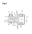
- Fig. 4 is a sectional view illustrating the middle slide rail, guide body, and movable arm depicted in Fig. 3 ;
- Fig. 5 is a (partly abridged) sectional view taken along the line V-V of Fig. 4 ;
- Fig. 6 is a set of enlarged plan views illustrating the positional relationship of the movable arm with respect to the guide body when opening and closing the slide door depicted in Fig. 3 ;
- Fig. 7 is a set of enlarged plan views schematically illustrating a conventional vehicle door structure in which an arm rotatably attached to a slide door is integrated with a guide body.
- Fig. 1 is a side view illustrating a vehicle equipped with one embodiment of the vehicle door structure in accordance with the present invention.
- the vehicle door structure 1 of this embodiment is applied to a side part of a vehicle body.
- the side part of the vehicle body 2 is formed with a front door opening 3 located beside front seats and a rear door opening 4 located beside a luggage compartment disposed behind the front seats.
- the front door opening 3 is opened and closed by a front door 5.
- the rear door opening 4 is opened and closed by a slidably openable and closable slide door 6 and a swingably openable and closable swing door 7.
- the slide door 6 is constructed such as to slide longitudinally of the vehicle body 2 as illustrated in Fig. 2 , thereby opening and closing a front region of the rear door opening 4. When fully opened, the slide door 6 is located on the outside of the swing door 7 and overlies the latter.
- the swing door 7 is constructed so as to rotate with respect to the vehicle body 2 when the slide door 6 is fully opened to overlie the swing door 7, thereby opening and closing a rear region of the rear door opening 4 in cooperation with the slide door 6.
- the outer surface of the slide door 6 is provided with an outer door opening and closing handle 8, while the inner surface of the slide door 6 is provided with an inner door opening and closing handle 9.
- a front end part of the swing door 7 is provided with a door opening and closing handle 10.
- the vehicle door structure 1 comprises slide support mechanisms 11A to 11C for supporting the slide door 6 such that the latter is slidable longitudinally of the vehicle body 2 and a rotary support mechanism 12 for supporting the swing door 7 such that the latter is rotatable with respect to the vehicle body 2.
- the slide support mechanism 11A has an upper slide rail 13 disposed in the upper part of the vehicle body 2 so as to extend longitudinally of the vehicle body 2 (in the opening/closing direction of the slide door 6) and an upper roller 14 disposed in the upper part of the front end of the slide door 6 and adapted to be guided by the upper slide rail 13 when opening and closing the slide door 6.
- the slide support mechanism 11B has a lower slide rail 15 disposed in the lower part of the vehicle body 2 so as to extend longitudinally of the vehicle body 2 and a lower roller 16 disposed in the lower part of the front end of the slide door 6 and adapted to be guided by the lower slide rail 15 when opening and closing the slide door 6.
- the slide support mechanism 11C has a middle slide rail 17 provided with the swing door 7 so as to extend longitudinally of the vehicle body 2 and a guide body 18 disposed in a rear end part of the slide door 6 and adapted to be guided by the middle slide rail 15 when opening and closing the slide door 6. Structures of the middle slide rail 15 and guide body 18 will be explained later in detail.
- the rollers 14, 16 are supported so as to be freely rotatable by respective brackets 19 attached to the upper and lower parts of the front end of the slide door 6.
- Latches 20 are attached to the brackets 19.
- the rotary support mechanism 12 has two, i.e., upper and lower, hinges 22 for rotatably connecting a rear pillar 21, which is provided in a rear end part of the vehicle body 2, and the swing door 7 to each other.
- the vehicle door structure 1 further comprises a lock mechanism 23 for locking the slide door 6 and swing door 7 with each other when the slide door 6 is fully opened and two, i.e., upper and lower, lock mechanisms 24 for locking the slide door 6 and swing door 7 with each other when the slide door 6 is fully closed so as to overlie the swing door 7.
- the lock mechanism 23 is constituted by a latch 25 attached to the rear end part of the slide door 6 and a striker 26 attached to the front end part of the swing door 7 and adapted to engage the latch 25.
- a latch 25 attached to the rear end part of the slide door 6
- a striker 26 attached to the front end part of the swing door 7 and adapted to engage the latch 25.
- the lock mechanisms 24 are constituted by the two latches 20 respectively attached to the upper and lower parts of the front end of the slide door 6 and two strikers 27 respectively attached to the upper and lower parts of the front end of the swing door 7 and adapted to engage the latches 20.
- the lock on the slide door 6 and swing door 7 can be released by operating the outer door opening and closing handle 8 or inner door opening and closing handle 9.
- the middle slide rail 17 is attached to the swing door 7 so as to extend longitudinally of the vehicle body 2 (in the opening/closing direction of the slide door 6).
- a front end part (end part on the slide door 6 full close side) of the middle slide rail 17 is formed with a curved rail part 17a curving into the vehicle body 2. Therefore, when the slide door 6 is slid from its full close state to the rear side of the vehicle body 2 so as to open, it moves to the outside of the vehicle body 2 and overlies the swing door 7 as mentioned above.
- the middle slide rail 17 slidably supports the guide body 18.
- the guide body 18 has a pair of, i.e., front and rear, horizontal rollers 28 and a vertical roller 29 which are guided by the middle slide rail 17.
- the vertical roller 29 is arranged between the pair of horizontal rollers 28.
- the horizontal rollers 28 and vertical roller 29 are supported so as to be freely rotatable by a bracket 30 through pins 31, 32, respectively.
- the bracket 30 is formed with a guide rail part 33 having a U-shaped cross section and extending longitudinally of the vehicle body 2.
- a movable arm 34 is attached to the rear end part of the slide door 6 through an attachment base 35 having a hat-shaped cross section and upper and lower pins 36 so as to be rotatable about an axis extending vertically of the vehicle body 2.
- a leading end part of the movable arm 34 is provided with a slider part 37 adapted to engage the guide rail part 33 of the bracket 30.
- the slider part 37 is movable longitudinally of the guide body 18 (in the opening/closing direction of the slide door 6) along the guide rail part 33. This can change the longitudinal position of the movable arm 34 with respect to the guide body 18.
- Figs. 4 and 5 omit the slide door 6, while Fig. 5 further omits the attachment base 35.
- a front end part of the bracket 30 is provided with a stopper pin 38 for regulating the movement of the slider part 37 with respect to the front side of the bracket 30.
- a rear end part of the bracket 30 is provided with a stopper wall 39 for regulating the movement of the slider part 37 with respect to the rear side of the bracket 30.
- the movable arm 34 When fully closing the slide door 6 by sliding it to the front side of the vehicle body 2 in thus constructed vehicle door structure 1, the movable arm 34 is moved to the front end side of the guide body 18 as illustrated in Figs. 3 and 6(a) .
- the lock mechanism 23 locks the slide door 6 with respect to the vehicle body 2 and swing door 7, whereby the position of the movable arm 34 is held on the front end side of the guide body 18.
- Fig. 6(a) omits the slide door 6.
- the movable arm 34 When fully opening the slide door 6 by sliding it to the rear side of the vehicle body 2, on the other hand, the movable arm 34 is moved to the rear end side of the guide body 18 as illustrated in Figs. 3 and 6(b) .
- the lock mechanisms 24 lock the slide door 6 with respect to the swing door 7, whereby the position of the movable arm 34 is held on the rear end side of the guide body 18.
- Fig. 6(b) also omits the slide door 6.
- an arm rotatably attached to the rear end part of the slide door is integrated with the guide body.
- an arm 50 rotatably attached to a rear end part of the slide door 6 is secured to a rear end part of a guide body 51.
- the arm 50 rotatably attached to the rear end part of the slide door 6 is secured to a front end part of the guide body 51.
- the amount of sliding the slide door 6 for fully opening the same is greater than that in the case where the arm 50 is secured to the front end part of the guide body 51, whereby the opening area of the front region of the rear door opening 4 can be increased.
- the amount of entry X of the guide body 51 to the inside of the vehicle body 2 when fully closing the slide door 6 is greater than that in the case where the arm 50 is secured to the front end part of the guide body 51, which makes it necessary for the curved rail part 17a of the middle slide rail 17 to extend long into the vehicle body 2, thereby correspondingly narrowing the luggage compartment space.
- the amount of entry X of the guide body 51 to the inside of the vehicle body 2 when fully closing the slide door 6 is smaller than that in the case where the arm 50 is secured to the rear end part of the guide body 51, which makes it unnecessary for the curved rail part 17a of the middle slide rail 17 to extend long into the vehicle body 2, whereby a wide luggage compartment space can be secured.
- the amount of sliding the slide door 6 when fully opening the same is smaller than that in the case where the arm 50 is secured to the rear end part of the guide body 51, so that the rear end of the slide door 6 is displaced forward by the decrease Y in amount of sliding, whereby the opening area of the front region of the rear door opening 4 becomes smaller.
- this embodiment is constructed such that the movable arm 34 rotatably attached to the rear end part of the slide door 6 is movable longitudinally of the guide body 18, which is guided along the middle slide rail 17, and thus can secure a wide luggage compartment space and increase the opening area of the rear door opening 4 at the same time.
- the movable arm 34 is moved to the front end part of the guide body 18 as illustrated in Fig. 6(a) , so that the amount of entry of the guide body 18 into the vehicle body 2 can be made smaller than that in the case where the movable arm 34 is located at the rear end part of the guide body 18. This makes it unnecessary for the curved rail part 17a of the middle slide rail 17 to extend long into the vehicle body 2, whereby the luggage compartment space can be made wider.
- the movable arm 34 When fully opening the slide door 6 by sliding it to the rear side of the vehicle body 2, on the other hand, the movable arm 34 is moved to the rear end part of the guide body 18 as illustrated in Fig. 6(b) , so that the amount of sliding the slide door 6 can be made greater than that in the case where the movable arm 34 is located at the front end part of the guide body 18. This correspondingly displaces the slide door 6 rearward and thus can increase the opening area of the front region of the rear door opening 4.
- the present invention is not limited to the above-mentioned embodiment.
- the above-mentioned embodiment moves the movable arm 34 longitudinally of the guide body 18 so that the longitudinal position of the movable arm 24 is changeable with respect to the guide body 18, this structure is not restrictive; the movable arm 34 may be rotated so that the longitudinal position of the movable arm 24 is changeable with respect to the guide body 18.
- the vehicle door structure of the present invention is also applicable to those constructed such that the slide door 6 opens and closes the rear region of the rear door opening 4 while the swing door 7 opens and closes the front region of the rear door opening 4 in cooperation with the slide door 6.
- the vehicle door structure of the present invention is also applicable to those equipped with slide and swing doors for opening and closing a door opening provided in the rear part of the vehicle body 2.
- the vehicle door structure of the present invention is also applicable to the one in which only a slide door opens and closes a door opening provided in a side or rear part of the vehicle body without the swing door.
- a vehicle door structure which can suppress the amount of entry of a guide body into a vehicle body when fully closing a slide door and increase the amount of sliding the slide door when fully opening the slide door is provided.
- a vehicle door structure 1 comprises a slide door 6 for opening and closing a front region of a rear door opening, a swing door 7 for opening and closing a rear region of the rear door opening in cooperation with the slide door 6, a middle slide rail 17 attached to the swing door 7 so as to extend longitudinally of the vehicle body, a guide body 18 adapted to be guided by the middle slide rail 17 when opening and closing the slide door 6, and a movable arm 34 rotatably attached to the slide door 6 and adapted to engage the guide body 18.
- the movable arm 34 is movable longitudinally of the vehicle body with respect to the guide body 18.
Landscapes
- Engineering & Computer Science (AREA)
- Mechanical Engineering (AREA)
- Civil Engineering (AREA)
- Structural Engineering (AREA)
- Support Devices For Sliding Doors (AREA)
Abstract
A vehicle door structure which can suppress the amount of entry of a guide body into a vehicle body when fully closing a slide door and increase the amount of sliding the slide door when fully opening the slide door is provided. A vehicle door structure 1 comprises a slide door 6 for opening and closing a front region of a rear door opening, a swing door 7 for opening and closing a rear region of the rear door opening in cooperation with the slide door 6, a middle slide rail 17 attached to the swing door 7 so as to extend longitudinally of the vehicle body, a guide body 18 adapted to be guided by the middle slide rail 17 when opening and closing the slide door 6, and a movable arm 34 rotatably attached to the slide door 6 and adapted to engage the guide body 18. The movable arm 34 is movable longitudinally of the vehicle body with respect to the guide body 18.
Description
- The present invention relates to a vehicle door structure equipped with a slidably openable and closable slide door.
- As an example of conventional vehicle door structures, one described in Japanese Patent Application Laid-Open No.
2001-113947 2001-113947 - In the vehicle door structure of the prior art mentioned above, the slide door and the roller bracket are connected to each other with an arm. Since the arm is connected to the front end part of the roller bracket here, the amount of entry of the roller body (guide body) to the inside of the vehicle at the time when the slide door is fully closed can be suppressed. Hence, it is unnecessary for the front end part (curved rail part) of the guide rail to extend long into the vehicle body, whereby a correspondingly wider space can be attained in the compartment. However, the arm connected to the front end part of the roller bracket limits the amount of sliding (amount of opening) the slide door when fully opening the slide door, thereby hindering the door opening from increasing its opening area.
- It is an object of the present invention to provide a vehicle door structure which can suppress the amount of entry of the guide body into the vehicle body when fully closing the slide door and increase the amount of sliding the slide door when fully opening the slide door.
- In one aspect, the present invention provides a vehicle door structure comprising a slide door for opening and closing a region of at least a part of a door opening provided in a side or rear part of a vehicle body; the vehicle door structure further comprising a slide rail disposed so as to extend in an opening/closing direction of the slide door, a guide body adapted to be guided by the slide rail, and a movable arm rotatably attached to the slide door and adapted to engage the guide body; wherein an end part of the slide rail on a side to fully close the slide door is formed with a curved rail part curving into the vehicle body; and wherein the movable arm is constructed such that a position thereof with respect to the guide body in the slide door opening/closing direction is changeable.
- For fully closing the slide door in thus constructed vehicle door structure of the present invention, the movable arm is positioned on the slide door full close side with respect to the guide body, so as to suppress the amount of entry of the guide body into the vehicle body when moving the slide door to the full close side. For fully opening the slide door, on the other hand, the movable arm is positioned on the slide door full open side with respect to the guide body, so as to suppress the amount of sliding (amount of opening) the slide door when moving the slide door to the full open side.
- One embodiment may be constructed such that the guide body is provided with a guide rail part extending in the slide door opening/closing direction, while the movable arm is provided with a slider part movable in the slide door opening/closing direction along the guide rail part. In this case, moving the slider part in the slide door opening/closing direction along the guide rail part can easily change the position of the movable arm in the slide door opening/closing direction with respect to the guide body.
- One embodiment may further comprise a swing door for opening and closing the other region of the door opening in cooperation with the slide door, the slide rail being attached to the swing door. In this case, the present invention can easily be applied to a vehicle door structure comprising a slide door and a swing door.
- The present invention can suppress the amount of entry of the guide body into the vehicle body when fully closing the slide door, which makes it unnecessary to secure a large space for the curved part of the guide rail on the inside of the vehicle body, whereby the space within the compartment can be expanded. It can also enhance the amount of sliding (amount of opening) the slide door when fully opening the same, thereby increasing the opening area of the door opening.
-
Fig. 1 is a side view illustrating a vehicle equipped with one embodiment of the vehicle door structure in accordance with the present invention; -
Fig. 2 is a perspective view illustrating how a slide door depicted inFig. 1 opens and closes; -
Fig. 3 is a plan view schematically illustrating the slide door and middle slide rail depicted inFig. 1 ; -
Fig. 4 is a sectional view illustrating the middle slide rail, guide body, and movable arm depicted inFig. 3 ; -
Fig. 5 is a (partly abridged) sectional view taken along the line V-V ofFig. 4 ; -
Fig. 6 is a set of enlarged plan views illustrating the positional relationship of the movable arm with respect to the guide body when opening and closing the slide door depicted inFig. 3 ; and -
Fig. 7 is a set of enlarged plan views schematically illustrating a conventional vehicle door structure in which an arm rotatably attached to a slide door is integrated with a guide body. - In the following, preferred embodiments of the vehicle door structure in accordance with the present invention will be explained in detail with reference to the drawings.
-
Fig. 1 is a side view illustrating a vehicle equipped with one embodiment of the vehicle door structure in accordance with the present invention. In this drawing, thevehicle door structure 1 of this embodiment is applied to a side part of a vehicle body. The side part of thevehicle body 2 is formed with a front door opening 3 located beside front seats and arear door opening 4 located beside a luggage compartment disposed behind the front seats. Thefront door opening 3 is opened and closed by afront door 5. - The
rear door opening 4 is opened and closed by a slidably openable andclosable slide door 6 and a swingably openable andclosable swing door 7. Theslide door 6 is constructed such as to slide longitudinally of thevehicle body 2 as illustrated inFig. 2 , thereby opening and closing a front region of therear door opening 4. When fully opened, theslide door 6 is located on the outside of theswing door 7 and overlies the latter. - The
swing door 7 is constructed so as to rotate with respect to thevehicle body 2 when theslide door 6 is fully opened to overlie theswing door 7, thereby opening and closing a rear region of the rear door opening 4 in cooperation with theslide door 6. - The outer surface of the
slide door 6 is provided with an outer door opening andclosing handle 8, while the inner surface of theslide door 6 is provided with an inner door opening andclosing handle 9. A front end part of theswing door 7 is provided with a door opening andclosing handle 10. - The
vehicle door structure 1 comprisesslide support mechanisms 11A to 11C for supporting theslide door 6 such that the latter is slidable longitudinally of thevehicle body 2 and arotary support mechanism 12 for supporting theswing door 7 such that the latter is rotatable with respect to thevehicle body 2. - The
slide support mechanism 11A has anupper slide rail 13 disposed in the upper part of thevehicle body 2 so as to extend longitudinally of the vehicle body 2 (in the opening/closing direction of the slide door 6) and anupper roller 14 disposed in the upper part of the front end of theslide door 6 and adapted to be guided by theupper slide rail 13 when opening and closing theslide door 6. - The
slide support mechanism 11B has alower slide rail 15 disposed in the lower part of thevehicle body 2 so as to extend longitudinally of thevehicle body 2 and alower roller 16 disposed in the lower part of the front end of theslide door 6 and adapted to be guided by thelower slide rail 15 when opening and closing theslide door 6. - The
slide support mechanism 11C has amiddle slide rail 17 provided with theswing door 7 so as to extend longitudinally of thevehicle body 2 and aguide body 18 disposed in a rear end part of theslide door 6 and adapted to be guided by themiddle slide rail 15 when opening and closing theslide door 6. Structures of themiddle slide rail 15 andguide body 18 will be explained later in detail. - As illustrated in
Fig. 2 , therollers respective brackets 19 attached to the upper and lower parts of the front end of theslide door 6. Latches 20 (seeFig. 1 ) are attached to thebrackets 19. - The
rotary support mechanism 12 has two, i.e., upper and lower, hinges 22 for rotatably connecting arear pillar 21, which is provided in a rear end part of thevehicle body 2, and theswing door 7 to each other. - The
vehicle door structure 1 further comprises alock mechanism 23 for locking theslide door 6 andswing door 7 with each other when theslide door 6 is fully opened and two, i.e., upper and lower,lock mechanisms 24 for locking theslide door 6 andswing door 7 with each other when theslide door 6 is fully closed so as to overlie theswing door 7. - The
lock mechanism 23 is constituted by alatch 25 attached to the rear end part of theslide door 6 and astriker 26 attached to the front end part of theswing door 7 and adapted to engage thelatch 25. When theslide door 6 is fully closed so that thelatch 25 engages thestriker 26, theslide door 6 andswing door 7 are locked with each other. The lock on theslide door 6 andswing door 7 can be released by operating the outer door opening and closinghandle 8 or inner door opening andclosing handle 9. - The
lock mechanisms 24 are constituted by the twolatches 20 respectively attached to the upper and lower parts of the front end of theslide door 6 and twostrikers 27 respectively attached to the upper and lower parts of the front end of theswing door 7 and adapted to engage thelatches 20. When theslide door 6 is fully opened so that thelatches 20 engage thestrikers 27, theslide door 6 andswing door 7 are locked with each other. The lock on theslide door 6 andswing door 7 can be released by operating the outer door opening and closinghandle 8 or inner door opening andclosing handle 9. - When the
slide door 6 is fully opened so that thelock mechanisms 24 lock theslide door 6 andswing door 7 with each other, the upper andlower rollers lower slide rails slide door 6 is supported by theswing door 7 alone through thelock mechanisms 24,middle slide rail 17, andguide body 18, so as to be rotatable integrally with theswing door 7. - As illustrated in
Fig. 3 , themiddle slide rail 17 is attached to theswing door 7 so as to extend longitudinally of the vehicle body 2 (in the opening/closing direction of the slide door 6). A front end part (end part on theslide door 6 full close side) of themiddle slide rail 17 is formed with acurved rail part 17a curving into thevehicle body 2. Therefore, when theslide door 6 is slid from its full close state to the rear side of thevehicle body 2 so as to open, it moves to the outside of thevehicle body 2 and overlies theswing door 7 as mentioned above. - The
middle slide rail 17 slidably supports theguide body 18. As illustrated inFigs. 4 and5 , theguide body 18 has a pair of, i.e., front and rear,horizontal rollers 28 and avertical roller 29 which are guided by themiddle slide rail 17. Thevertical roller 29 is arranged between the pair ofhorizontal rollers 28. Thehorizontal rollers 28 andvertical roller 29 are supported so as to be freely rotatable by abracket 30 throughpins bracket 30 is formed with aguide rail part 33 having a U-shaped cross section and extending longitudinally of thevehicle body 2. - As illustrated in
Figs. 3 to 5 , amovable arm 34 is attached to the rear end part of theslide door 6 through anattachment base 35 having a hat-shaped cross section and upper andlower pins 36 so as to be rotatable about an axis extending vertically of thevehicle body 2.
A leading end part of themovable arm 34 is provided with aslider part 37 adapted to engage theguide rail part 33 of thebracket 30. Theslider part 37 is movable longitudinally of the guide body 18 (in the opening/closing direction of the slide door 6) along theguide rail part 33. This can change the longitudinal position of themovable arm 34 with respect to theguide body 18.Figs. 4 and5 omit theslide door 6, whileFig. 5 further omits theattachment base 35. - A front end part of the
bracket 30 is provided with astopper pin 38 for regulating the movement of theslider part 37 with respect to the front side of thebracket 30. A rear end part of thebracket 30 is provided with astopper wall 39 for regulating the movement of theslider part 37 with respect to the rear side of thebracket 30. - When fully closing the
slide door 6 by sliding it to the front side of thevehicle body 2 in thus constructedvehicle door structure 1, themovable arm 34 is moved to the front end side of theguide body 18 as illustrated inFigs. 3 and6(a) . Here, thelock mechanism 23 locks theslide door 6 with respect to thevehicle body 2 andswing door 7, whereby the position of themovable arm 34 is held on the front end side of theguide body 18.Fig. 6(a) omits theslide door 6. - When fully opening the
slide door 6 by sliding it to the rear side of thevehicle body 2, on the other hand, themovable arm 34 is moved to the rear end side of theguide body 18 as illustrated inFigs. 3 and6(b) . Here, thelock mechanisms 24 lock theslide door 6 with respect to theswing door 7, whereby the position of themovable arm 34 is held on the rear end side of theguide body 18.Fig. 6(b) also omits theslide door 6. - In the conventional vehicle door structure, an arm rotatably attached to the rear end part of the slide door is integrated with the guide body. In the one illustrated in
Fig. 7(a) , anarm 50 rotatably attached to a rear end part of theslide door 6 is secured to a rear end part of aguide body 51. In the one illustrated inFig. 7(b) , thearm 50 rotatably attached to the rear end part of theslide door 6 is secured to a front end part of theguide body 51. - In the case where the
arm 50 is secured to the rear end part of theguide body 51, the amount of sliding theslide door 6 for fully opening the same is greater than that in the case where thearm 50 is secured to the front end part of theguide body 51, whereby the opening area of the front region of the rear door opening 4 can be increased. In the case where thearm 50 is secured to the rear end part of theguide body 51, however, the amount of entry X of theguide body 51 to the inside of thevehicle body 2 when fully closing theslide door 6 is greater than that in the case where thearm 50 is secured to the front end part of theguide body 51, which makes it necessary for thecurved rail part 17a of themiddle slide rail 17 to extend long into thevehicle body 2, thereby correspondingly narrowing the luggage compartment space. - In the case where the
arm 50 is secured to the front end part of theguide body 51, on the other hand, the amount of entry X of theguide body 51 to the inside of thevehicle body 2 when fully closing theslide door 6 is smaller than that in the case where thearm 50 is secured to the rear end part of theguide body 51, which makes it unnecessary for thecurved rail part 17a of themiddle slide rail 17 to extend long into thevehicle body 2, whereby a wide luggage compartment space can be secured. In the case where thearm 50 is secured to the front end part of theguide body 51, however, the amount of sliding theslide door 6 when fully opening the same is smaller than that in the case where thearm 50 is secured to the rear end part of theguide body 51, so that the rear end of theslide door 6 is displaced forward by the decrease Y in amount of sliding, whereby the opening area of the front region of the rear door opening 4 becomes smaller. - By contrast, this embodiment is constructed such that the
movable arm 34 rotatably attached to the rear end part of theslide door 6 is movable longitudinally of theguide body 18, which is guided along themiddle slide rail 17, and thus can secure a wide luggage compartment space and increase the opening area of the rear door opening 4 at the same time. - That is, when fully closing the
slide door 6 by sliding it to the front side of thevehicle body 2, themovable arm 34 is moved to the front end part of theguide body 18 as illustrated inFig. 6(a) , so that the amount of entry of theguide body 18 into thevehicle body 2 can be made smaller than that in the case where themovable arm 34 is located at the rear end part of theguide body 18. This makes it unnecessary for thecurved rail part 17a of themiddle slide rail 17 to extend long into thevehicle body 2, whereby the luggage compartment space can be made wider. - When fully opening the
slide door 6 by sliding it to the rear side of thevehicle body 2, on the other hand, themovable arm 34 is moved to the rear end part of theguide body 18 as illustrated inFig. 6(b) , so that the amount of sliding theslide door 6 can be made greater than that in the case where themovable arm 34 is located at the front end part of theguide body 18. This correspondingly displaces theslide door 6 rearward and thus can increase the opening area of the front region of therear door opening 4. - The present invention is not limited to the above-mentioned embodiment. For example, while the above-mentioned embodiment moves the
movable arm 34 longitudinally of theguide body 18 so that the longitudinal position of themovable arm 24 is changeable with respect to theguide body 18, this structure is not restrictive; themovable arm 34 may be rotated so that the longitudinal position of themovable arm 24 is changeable with respect to theguide body 18. - Though the above-mentioned embodiment is constructed such that the
slide door 6 opens and closes the front region of the rear door opening 4 while theswing door 7 opens and closes the rear region of the rear door opening 4 in cooperation with theslide door 6, the vehicle door structure of the present invention is also applicable to those constructed such that theslide door 6 opens and closes the rear region of the rear door opening 4 while theswing door 7 opens and closes the front region of the rear door opening 4 in cooperation with theslide door 6. The vehicle door structure of the present invention is also applicable to those equipped with slide and swing doors for opening and closing a door opening provided in the rear part of thevehicle body 2. - The vehicle door structure of the present invention is also applicable to the one in which only a slide door opens and closes a door opening provided in a side or rear part of the vehicle body without the swing door.
A vehicle door structure which can suppress the amount of entry of a guide body into a vehicle body when fully closing a slide door and increase the amount of sliding the slide door when fully opening the slide door is provided. Avehicle door structure 1 comprises aslide door 6 for opening and closing a front region of a rear door opening, aswing door 7 for opening and closing a rear region of the rear door opening in cooperation with theslide door 6, amiddle slide rail 17 attached to theswing door 7 so as to extend longitudinally of the vehicle body, aguide body 18 adapted to be guided by themiddle slide rail 17 when opening and closing theslide door 6, and amovable arm 34 rotatably attached to theslide door 6 and adapted to engage theguide body 18. Themovable arm 34 is movable longitudinally of the vehicle body with respect to theguide body 18.
Claims (3)
- A vehicle door structure comprising a slide door for opening and closing a region of at least a part of a door opening provided in a side or rear part of a vehicle body, the vehicle door structure further comprising:a slide rail disposed so as to extend in an opening/closing direction of the slide door,a guide body adapted to be guided by the slide rail, anda movable arm rotatably attached to the slide door and adapted to engage the guide body;wherein an end part of the slide rail on a side to fully close the slide door is formed with a curved rail part curving into the vehicle body; andwherein the movable arm is constructed such that a position thereof with respect to the guide body in the slide door opening/closing direction is changeable.
- A vehicle door structure according to claim 1, wherein the guide body is provided with a guide rail part extending in the slide door opening/closing direction; and
wherein the movable arm is provided with a slider part movable in the slide door opening/closing direction along the guide rail part. - A vehicle door structure according to claim 1 or 2, further comprising a swing door for opening and closing the other region of the door opening in cooperation with the slide door;
wherein the slide rail is attached to the swing door.
Applications Claiming Priority (1)
| Application Number | Priority Date | Filing Date | Title |
|---|---|---|---|
| JP2012207410A JP2014061766A (en) | 2012-09-20 | 2012-09-20 | Door structure for vehicle |
Publications (1)
| Publication Number | Publication Date |
|---|---|
| EP2711217A2 true EP2711217A2 (en) | 2014-03-26 |
Family
ID=48874139
Family Applications (1)
| Application Number | Title | Priority Date | Filing Date |
|---|---|---|---|
| EP13177407.7A Withdrawn EP2711217A2 (en) | 2012-09-20 | 2013-07-22 | Vehicle door structure |
Country Status (4)
| Country | Link |
|---|---|
| US (1) | US20140075843A1 (en) |
| EP (1) | EP2711217A2 (en) |
| JP (1) | JP2014061766A (en) |
| CN (1) | CN103660880A (en) |
Cited By (1)
| Publication number | Priority date | Publication date | Assignee | Title |
|---|---|---|---|---|
| CN104975768A (en) * | 2014-04-09 | 2015-10-14 | 现代自动车株式会社 | Sliding door locking device of vehicle |
Families Citing this family (15)
| Publication number | Priority date | Publication date | Assignee | Title |
|---|---|---|---|---|
| JP2016084078A (en) * | 2014-10-28 | 2016-05-19 | 株式会社豊田自動織機 | Vehicle door structure |
| KR101637289B1 (en) * | 2014-11-06 | 2016-07-07 | 현대자동차 주식회사 | Sliding door device for vehicle |
| CN104477016A (en) * | 2014-12-10 | 2015-04-01 | 衡阳泰豪通信车辆有限公司 | Small sliding door suitable for limited space |
| EP3199734B1 (en) * | 2016-01-27 | 2018-10-10 | Ford Global Technologies, LLC | Centre track design for a sliding door |
| CN106585340B (en) * | 2016-12-13 | 2020-09-18 | 广州汽车集团股份有限公司 | Automobile sliding door and positioning device thereof |
| JP6949072B2 (en) * | 2019-03-27 | 2021-10-13 | 本田技研工業株式会社 | Car body structure |
| US11585137B2 (en) | 2019-07-02 | 2023-02-21 | The Braun Corporation | Modified door operation for a motorized vehicle |
| KR102682888B1 (en) * | 2019-09-19 | 2024-07-09 | 현대자동차주식회사 | Locking structure for center rail of opposed type sliding door |
| US11808065B2 (en) * | 2019-11-07 | 2023-11-07 | Hyundai Motor Company | Sliding/swing composite door for vehicle |
| KR102908996B1 (en) * | 2019-11-12 | 2026-01-08 | 현대자동차주식회사 | Vehicle door opening and closing apparatus |
| KR102682817B1 (en) * | 2019-12-03 | 2024-07-09 | 현대자동차주식회사 | Structure for preventing movement of opposed type sliding doors |
| JP7334650B2 (en) * | 2020-02-18 | 2023-08-29 | トヨタ車体株式会社 | Vehicle sliding door device |
| EP3932709B1 (en) * | 2020-06-30 | 2023-10-18 | Ningbo Geely Automobile Research & Development Co. Ltd. | A vehicle door system and a method for improving durability of a door system |
| JP7597557B2 (en) * | 2020-11-13 | 2024-12-10 | ナブテスコ株式会社 | Plug door device |
| KR20220085133A (en) * | 2020-12-15 | 2022-06-22 | 현대자동차주식회사 | Side sill for mounting sliding door of vehicle |
Citations (1)
| Publication number | Priority date | Publication date | Assignee | Title |
|---|---|---|---|---|
| JP2001113947A (en) | 1999-10-15 | 2001-04-24 | Toyota Auto Body Co Ltd | Motor-driven slide door device of vehicle |
Family Cites Families (14)
| Publication number | Priority date | Publication date | Assignee | Title |
|---|---|---|---|---|
| JPS5387426A (en) * | 1977-01-12 | 1978-08-01 | Nissan Motor Co Ltd | Apparatus for sliding slide door for vehicle |
| JPS62110525A (en) * | 1985-11-06 | 1987-05-21 | Daihatsu Motor Co Ltd | Upper supporting mechanism of slide door for automobile |
| JPS62218221A (en) * | 1986-03-19 | 1987-09-25 | Daihatsu Motor Co Ltd | Upper part supporting mechanism for automobile slide door |
| JPH057059Y2 (en) * | 1987-05-27 | 1993-02-23 | ||
| US4887390A (en) * | 1987-12-18 | 1989-12-19 | Masco Industries, Inc. | Powered sliding door opener/closer for vehicles |
| JPH0260825A (en) * | 1988-08-29 | 1990-03-01 | Daihatsu Motor Co Ltd | Upper support structure for on-vehicle sliding door |
| US5895089A (en) * | 1997-03-31 | 1999-04-20 | Ford Global Technologies, Inc. | Dual function adjustable bumper for automotive vehicle sliding door |
| US6328374B1 (en) * | 2000-06-21 | 2001-12-11 | Ford Global Technologies, Inc. | Fully-openable slidable vehicle door assembly |
| US6932417B2 (en) * | 2003-09-23 | 2005-08-23 | Gecom Corporation | Vehicle sliding door with extended travel |
| US20060197357A1 (en) * | 2005-03-03 | 2006-09-07 | Arvinmeritor Technology, Llc | Vehicle door system |
| JP4750661B2 (en) * | 2006-09-28 | 2011-08-17 | 三井金属アクト株式会社 | Support structure for vehicle sliding door |
| US7641261B2 (en) * | 2008-03-11 | 2010-01-05 | Gm Global Technology Operations, Inc. | Extended travel sliding door mechanism |
| JP5644076B2 (en) * | 2009-08-27 | 2014-12-24 | 株式会社豊田自動織機 | Vehicle door structure |
| JP2011230568A (en) * | 2010-04-26 | 2011-11-17 | Mazda Motor Corp | Side part structure for vehicle |
-
2012
- 2012-09-20 JP JP2012207410A patent/JP2014061766A/en active Pending
-
2013
- 2013-07-22 EP EP13177407.7A patent/EP2711217A2/en not_active Withdrawn
- 2013-07-24 US US13/949,742 patent/US20140075843A1/en not_active Abandoned
- 2013-09-13 CN CN201310418557.2A patent/CN103660880A/en active Pending
Patent Citations (1)
| Publication number | Priority date | Publication date | Assignee | Title |
|---|---|---|---|---|
| JP2001113947A (en) | 1999-10-15 | 2001-04-24 | Toyota Auto Body Co Ltd | Motor-driven slide door device of vehicle |
Cited By (2)
| Publication number | Priority date | Publication date | Assignee | Title |
|---|---|---|---|---|
| CN104975768A (en) * | 2014-04-09 | 2015-10-14 | 现代自动车株式会社 | Sliding door locking device of vehicle |
| CN104975768B (en) * | 2014-04-09 | 2019-06-28 | 现代自动车株式会社 | Sliding door locking device for vehicles |
Also Published As
| Publication number | Publication date |
|---|---|
| US20140075843A1 (en) | 2014-03-20 |
| JP2014061766A (en) | 2014-04-10 |
| CN103660880A (en) | 2014-03-26 |
Similar Documents
| Publication | Publication Date | Title |
|---|---|---|
| US20140075843A1 (en) | Vehicle door structure | |
| US9016762B2 (en) | Vehicle door structure | |
| CN105984312A (en) | Vehicle door structure | |
| JP5633543B2 (en) | Vehicle door structure | |
| JP6064332B2 (en) | Sliding door device for vehicle | |
| US20120049577A1 (en) | Independent opposing-hinged access door | |
| US6932417B2 (en) | Vehicle sliding door with extended travel | |
| US20090230721A1 (en) | Extended Travel Sliding Door Mechanism | |
| US10480233B2 (en) | Hidden sliding door assembly for a motor vehicle | |
| CN105984310A (en) | Vehicle door structure | |
| EP2628618A2 (en) | Vehicle door structure | |
| JP2008190199A (en) | Vehicle door opening/closing structure | |
| JP2016215857A (en) | Door structure for vehicle | |
| US8235454B2 (en) | Vehicle with a sliding door | |
| EP2636551A2 (en) | Vehicle door structure | |
| US20120049581A1 (en) | Indexing door latch striker enabling complex door articulation | |
| JP3755603B2 (en) | Structure of sliding door for vehicle | |
| US8757676B2 (en) | Device for locking an opening panel of a motor vehicle | |
| KR20170029333A (en) | Slide door structure of vehicle | |
| JP3968072B2 (en) | Sliding door device for vehicle | |
| JP2003148024A (en) | Door lock device for automobile | |
| JP5440592B2 (en) | Vehicle door structure | |
| JP2013107556A (en) | Sliding door structure | |
| JP2016210233A (en) | Door structure for vehicle | |
| JP2015206204A (en) | Vehicle door structure |
Legal Events
| Date | Code | Title | Description |
|---|---|---|---|
| PUAI | Public reference made under article 153(3) epc to a published international application that has entered the european phase |
Free format text: ORIGINAL CODE: 0009012 |
|
| 17P | Request for examination filed |
Effective date: 20130722 |
|
| AK | Designated contracting states |
Kind code of ref document: A2 Designated state(s): AL AT BE BG CH CY CZ DE DK EE ES FI FR GB GR HR HU IE IS IT LI LT LU LV MC MK MT NL NO PL PT RO RS SE SI SK SM TR |
|
| AX | Request for extension of the european patent |
Extension state: BA ME |
|
| STAA | Information on the status of an ep patent application or granted ep patent |
Free format text: STATUS: THE APPLICATION HAS BEEN WITHDRAWN |
|
| 18W | Application withdrawn |
Effective date: 20140813 |