EP2711152A1 - Method for blow molding a hot-fill container with increased stretch ratios - Google Patents
Method for blow molding a hot-fill container with increased stretch ratios Download PDFInfo
- Publication number
- EP2711152A1 EP2711152A1 EP20130305142 EP13305142A EP2711152A1 EP 2711152 A1 EP2711152 A1 EP 2711152A1 EP 20130305142 EP20130305142 EP 20130305142 EP 13305142 A EP13305142 A EP 13305142A EP 2711152 A1 EP2711152 A1 EP 2711152A1
- Authority
- EP
- European Patent Office
- Prior art keywords
- preform
- container
- wall thickness
- end segment
- blow molding
- Prior art date
- Legal status (The legal status is an assumption and is not a legal conclusion. Google has not performed a legal analysis and makes no representation as to the accuracy of the status listed.)
- Granted
Links
Images



Classifications
-
- B—PERFORMING OPERATIONS; TRANSPORTING
- B65—CONVEYING; PACKING; STORING; HANDLING THIN OR FILAMENTARY MATERIAL
- B65D—CONTAINERS FOR STORAGE OR TRANSPORT OF ARTICLES OR MATERIALS, e.g. BAGS, BARRELS, BOTTLES, BOXES, CANS, CARTONS, CRATES, DRUMS, JARS, TANKS, HOPPERS, FORWARDING CONTAINERS; ACCESSORIES, CLOSURES, OR FITTINGS THEREFOR; PACKAGING ELEMENTS; PACKAGES
- B65D79/00—Kinds or details of packages, not otherwise provided for
- B65D79/005—Packages having deformable parts for indicating or neutralizing internal pressure-variations by other means than venting
- B65D79/008—Packages having deformable parts for indicating or neutralizing internal pressure-variations by other means than venting the deformable part being located in a rigid or semi-rigid container, e.g. in bottles or jars
- B65D79/0081—Packages having deformable parts for indicating or neutralizing internal pressure-variations by other means than venting the deformable part being located in a rigid or semi-rigid container, e.g. in bottles or jars in the bottom part thereof
-
- B—PERFORMING OPERATIONS; TRANSPORTING
- B29—WORKING OF PLASTICS; WORKING OF SUBSTANCES IN A PLASTIC STATE IN GENERAL
- B29B—PREPARATION OR PRETREATMENT OF THE MATERIAL TO BE SHAPED; MAKING GRANULES OR PREFORMS; RECOVERY OF PLASTICS OR OTHER CONSTITUENTS OF WASTE MATERIAL CONTAINING PLASTICS
- B29B11/00—Making preforms
- B29B11/14—Making preforms characterised by structure or composition
-
- B—PERFORMING OPERATIONS; TRANSPORTING
- B29—WORKING OF PLASTICS; WORKING OF SUBSTANCES IN A PLASTIC STATE IN GENERAL
- B29B—PREPARATION OR PRETREATMENT OF THE MATERIAL TO BE SHAPED; MAKING GRANULES OR PREFORMS; RECOVERY OF PLASTICS OR OTHER CONSTITUENTS OF WASTE MATERIAL CONTAINING PLASTICS
- B29B13/00—Conditioning or physical treatment of the material to be shaped
- B29B13/02—Conditioning or physical treatment of the material to be shaped by heating
- B29B13/023—Half-products, e.g. films, plates
- B29B13/024—Hollow bodies, e.g. tubes or profiles
-
- B—PERFORMING OPERATIONS; TRANSPORTING
- B29—WORKING OF PLASTICS; WORKING OF SUBSTANCES IN A PLASTIC STATE IN GENERAL
- B29C—SHAPING OR JOINING OF PLASTICS; SHAPING OF MATERIAL IN A PLASTIC STATE, NOT OTHERWISE PROVIDED FOR; AFTER-TREATMENT OF THE SHAPED PRODUCTS, e.g. REPAIRING
- B29C49/00—Blow-moulding, i.e. blowing a preform or parison to a desired shape within a mould; Apparatus therefor
- B29C49/071—Preforms or parisons characterised by their configuration, e.g. geometry, dimensions or physical properties
-
- B—PERFORMING OPERATIONS; TRANSPORTING
- B29—WORKING OF PLASTICS; WORKING OF SUBSTANCES IN A PLASTIC STATE IN GENERAL
- B29C—SHAPING OR JOINING OF PLASTICS; SHAPING OF MATERIAL IN A PLASTIC STATE, NOT OTHERWISE PROVIDED FOR; AFTER-TREATMENT OF THE SHAPED PRODUCTS, e.g. REPAIRING
- B29C49/00—Blow-moulding, i.e. blowing a preform or parison to a desired shape within a mould; Apparatus therefor
- B29C49/08—Biaxial stretching during blow-moulding
- B29C49/10—Biaxial stretching during blow-moulding using mechanical means for prestretching
- B29C49/12—Stretching rods
-
- B—PERFORMING OPERATIONS; TRANSPORTING
- B29—WORKING OF PLASTICS; WORKING OF SUBSTANCES IN A PLASTIC STATE IN GENERAL
- B29C—SHAPING OR JOINING OF PLASTICS; SHAPING OF MATERIAL IN A PLASTIC STATE, NOT OTHERWISE PROVIDED FOR; AFTER-TREATMENT OF THE SHAPED PRODUCTS, e.g. REPAIRING
- B29C49/00—Blow-moulding, i.e. blowing a preform or parison to a desired shape within a mould; Apparatus therefor
- B29C49/42—Component parts, details or accessories; Auxiliary operations
- B29C49/48—Moulds
- B29C49/54—Moulds for undercut articles
- B29C49/541—Moulds for undercut articles having a recessed undersurface
-
- B—PERFORMING OPERATIONS; TRANSPORTING
- B29—WORKING OF PLASTICS; WORKING OF SUBSTANCES IN A PLASTIC STATE IN GENERAL
- B29C—SHAPING OR JOINING OF PLASTICS; SHAPING OF MATERIAL IN A PLASTIC STATE, NOT OTHERWISE PROVIDED FOR; AFTER-TREATMENT OF THE SHAPED PRODUCTS, e.g. REPAIRING
- B29C49/00—Blow-moulding, i.e. blowing a preform or parison to a desired shape within a mould; Apparatus therefor
- B29C49/42—Component parts, details or accessories; Auxiliary operations
- B29C49/64—Heating or cooling preforms, parisons or blown articles
-
- B—PERFORMING OPERATIONS; TRANSPORTING
- B65—CONVEYING; PACKING; STORING; HANDLING THIN OR FILAMENTARY MATERIAL
- B65D—CONTAINERS FOR STORAGE OR TRANSPORT OF ARTICLES OR MATERIALS, e.g. BAGS, BARRELS, BOTTLES, BOXES, CANS, CARTONS, CRATES, DRUMS, JARS, TANKS, HOPPERS, FORWARDING CONTAINERS; ACCESSORIES, CLOSURES, OR FITTINGS THEREFOR; PACKAGING ELEMENTS; PACKAGES
- B65D1/00—Rigid or semi-rigid containers having bodies formed in one piece, e.g. by casting metallic material, by moulding plastics, by blowing vitreous material, by throwing ceramic material, by moulding pulped fibrous material or by deep-drawing operations performed on sheet material
- B65D1/02—Bottles or similar containers with necks or like restricted apertures, designed for pouring contents
- B65D1/0223—Bottles or similar containers with necks or like restricted apertures, designed for pouring contents characterised by shape
- B65D1/0261—Bottom construction
- B65D1/0276—Bottom construction having a continuous contact surface, e.g. Champagne-type bottom
-
- B—PERFORMING OPERATIONS; TRANSPORTING
- B29—WORKING OF PLASTICS; WORKING OF SUBSTANCES IN A PLASTIC STATE IN GENERAL
- B29B—PREPARATION OR PRETREATMENT OF THE MATERIAL TO BE SHAPED; MAKING GRANULES OR PREFORMS; RECOVERY OF PLASTICS OR OTHER CONSTITUENTS OF WASTE MATERIAL CONTAINING PLASTICS
- B29B11/00—Making preforms
- B29B11/06—Making preforms by moulding the material
- B29B11/08—Injection moulding
-
- B—PERFORMING OPERATIONS; TRANSPORTING
- B29—WORKING OF PLASTICS; WORKING OF SUBSTANCES IN A PLASTIC STATE IN GENERAL
- B29B—PREPARATION OR PRETREATMENT OF THE MATERIAL TO BE SHAPED; MAKING GRANULES OR PREFORMS; RECOVERY OF PLASTICS OR OTHER CONSTITUENTS OF WASTE MATERIAL CONTAINING PLASTICS
- B29B11/00—Making preforms
- B29B11/06—Making preforms by moulding the material
- B29B11/12—Compression moulding
-
- B—PERFORMING OPERATIONS; TRANSPORTING
- B29—WORKING OF PLASTICS; WORKING OF SUBSTANCES IN A PLASTIC STATE IN GENERAL
- B29C—SHAPING OR JOINING OF PLASTICS; SHAPING OF MATERIAL IN A PLASTIC STATE, NOT OTHERWISE PROVIDED FOR; AFTER-TREATMENT OF THE SHAPED PRODUCTS, e.g. REPAIRING
- B29C49/00—Blow-moulding, i.e. blowing a preform or parison to a desired shape within a mould; Apparatus therefor
- B29C49/42—Component parts, details or accessories; Auxiliary operations
- B29C49/48—Moulds
- B29C49/4823—Moulds with incorporated heating or cooling means
- B29C2049/4838—Moulds with incorporated heating or cooling means for heating moulds or mould parts
-
- B—PERFORMING OPERATIONS; TRANSPORTING
- B29—WORKING OF PLASTICS; WORKING OF SUBSTANCES IN A PLASTIC STATE IN GENERAL
- B29C—SHAPING OR JOINING OF PLASTICS; SHAPING OF MATERIAL IN A PLASTIC STATE, NOT OTHERWISE PROVIDED FOR; AFTER-TREATMENT OF THE SHAPED PRODUCTS, e.g. REPAIRING
- B29C49/00—Blow-moulding, i.e. blowing a preform or parison to a desired shape within a mould; Apparatus therefor
- B29C49/42—Component parts, details or accessories; Auxiliary operations
- B29C49/48—Moulds
- B29C2049/4879—Moulds characterised by mould configurations
- B29C2049/4882—Mould cavity geometry
-
- B—PERFORMING OPERATIONS; TRANSPORTING
- B29—WORKING OF PLASTICS; WORKING OF SUBSTANCES IN A PLASTIC STATE IN GENERAL
- B29C—SHAPING OR JOINING OF PLASTICS; SHAPING OF MATERIAL IN A PLASTIC STATE, NOT OTHERWISE PROVIDED FOR; AFTER-TREATMENT OF THE SHAPED PRODUCTS, e.g. REPAIRING
- B29C49/00—Blow-moulding, i.e. blowing a preform or parison to a desired shape within a mould; Apparatus therefor
- B29C49/42—Component parts, details or accessories; Auxiliary operations
- B29C49/48—Moulds
- B29C2049/4879—Moulds characterised by mould configurations
- B29C2049/4892—Mould halves consisting of an independent main and bottom part
-
- B—PERFORMING OPERATIONS; TRANSPORTING
- B29—WORKING OF PLASTICS; WORKING OF SUBSTANCES IN A PLASTIC STATE IN GENERAL
- B29C—SHAPING OR JOINING OF PLASTICS; SHAPING OF MATERIAL IN A PLASTIC STATE, NOT OTHERWISE PROVIDED FOR; AFTER-TREATMENT OF THE SHAPED PRODUCTS, e.g. REPAIRING
- B29C49/00—Blow-moulding, i.e. blowing a preform or parison to a desired shape within a mould; Apparatus therefor
- B29C49/42—Component parts, details or accessories; Auxiliary operations
- B29C49/78—Measuring, controlling or regulating
- B29C49/786—Temperature
- B29C2049/7864—Temperature of the mould
- B29C2049/78645—Temperature of the mould characterised by temperature values or ranges
-
- B—PERFORMING OPERATIONS; TRANSPORTING
- B29—WORKING OF PLASTICS; WORKING OF SUBSTANCES IN A PLASTIC STATE IN GENERAL
- B29C—SHAPING OR JOINING OF PLASTICS; SHAPING OF MATERIAL IN A PLASTIC STATE, NOT OTHERWISE PROVIDED FOR; AFTER-TREATMENT OF THE SHAPED PRODUCTS, e.g. REPAIRING
- B29C2949/00—Indexing scheme relating to blow-moulding
- B29C2949/07—Preforms or parisons characterised by their configuration
- B29C2949/0715—Preforms or parisons characterised by their configuration the preform having one end closed
-
- B—PERFORMING OPERATIONS; TRANSPORTING
- B29—WORKING OF PLASTICS; WORKING OF SUBSTANCES IN A PLASTIC STATE IN GENERAL
- B29C—SHAPING OR JOINING OF PLASTICS; SHAPING OF MATERIAL IN A PLASTIC STATE, NOT OTHERWISE PROVIDED FOR; AFTER-TREATMENT OF THE SHAPED PRODUCTS, e.g. REPAIRING
- B29C2949/00—Indexing scheme relating to blow-moulding
- B29C2949/07—Preforms or parisons characterised by their configuration
- B29C2949/072—Preforms or parisons characterised by their configuration having variable wall thickness
-
- B—PERFORMING OPERATIONS; TRANSPORTING
- B29—WORKING OF PLASTICS; WORKING OF SUBSTANCES IN A PLASTIC STATE IN GENERAL
- B29C—SHAPING OR JOINING OF PLASTICS; SHAPING OF MATERIAL IN A PLASTIC STATE, NOT OTHERWISE PROVIDED FOR; AFTER-TREATMENT OF THE SHAPED PRODUCTS, e.g. REPAIRING
- B29C2949/00—Indexing scheme relating to blow-moulding
- B29C2949/07—Preforms or parisons characterised by their configuration
- B29C2949/072—Preforms or parisons characterised by their configuration having variable wall thickness
- B29C2949/0724—Preforms or parisons characterised by their configuration having variable wall thickness at body portion
-
- B—PERFORMING OPERATIONS; TRANSPORTING
- B29—WORKING OF PLASTICS; WORKING OF SUBSTANCES IN A PLASTIC STATE IN GENERAL
- B29C—SHAPING OR JOINING OF PLASTICS; SHAPING OF MATERIAL IN A PLASTIC STATE, NOT OTHERWISE PROVIDED FOR; AFTER-TREATMENT OF THE SHAPED PRODUCTS, e.g. REPAIRING
- B29C2949/00—Indexing scheme relating to blow-moulding
- B29C2949/07—Preforms or parisons characterised by their configuration
- B29C2949/072—Preforms or parisons characterised by their configuration having variable wall thickness
- B29C2949/0725—Preforms or parisons characterised by their configuration having variable wall thickness at bottom portion
-
- B—PERFORMING OPERATIONS; TRANSPORTING
- B29—WORKING OF PLASTICS; WORKING OF SUBSTANCES IN A PLASTIC STATE IN GENERAL
- B29C—SHAPING OR JOINING OF PLASTICS; SHAPING OF MATERIAL IN A PLASTIC STATE, NOT OTHERWISE PROVIDED FOR; AFTER-TREATMENT OF THE SHAPED PRODUCTS, e.g. REPAIRING
- B29C2949/00—Indexing scheme relating to blow-moulding
- B29C2949/07—Preforms or parisons characterised by their configuration
- B29C2949/073—Preforms or parisons characterised by their configuration having variable diameter
-
- B—PERFORMING OPERATIONS; TRANSPORTING
- B29—WORKING OF PLASTICS; WORKING OF SUBSTANCES IN A PLASTIC STATE IN GENERAL
- B29C—SHAPING OR JOINING OF PLASTICS; SHAPING OF MATERIAL IN A PLASTIC STATE, NOT OTHERWISE PROVIDED FOR; AFTER-TREATMENT OF THE SHAPED PRODUCTS, e.g. REPAIRING
- B29C2949/00—Indexing scheme relating to blow-moulding
- B29C2949/07—Preforms or parisons characterised by their configuration
- B29C2949/076—Preforms or parisons characterised by their configuration characterised by the shape
- B29C2949/0768—Preforms or parisons characterised by their configuration characterised by the shape characterised by the shape of specific parts of preform
- B29C2949/077—Preforms or parisons characterised by their configuration characterised by the shape characterised by the shape of specific parts of preform characterised by the neck
- B29C2949/0772—Closure retaining means
- B29C2949/0773—Threads
-
- B—PERFORMING OPERATIONS; TRANSPORTING
- B29—WORKING OF PLASTICS; WORKING OF SUBSTANCES IN A PLASTIC STATE IN GENERAL
- B29C—SHAPING OR JOINING OF PLASTICS; SHAPING OF MATERIAL IN A PLASTIC STATE, NOT OTHERWISE PROVIDED FOR; AFTER-TREATMENT OF THE SHAPED PRODUCTS, e.g. REPAIRING
- B29C2949/00—Indexing scheme relating to blow-moulding
- B29C2949/07—Preforms or parisons characterised by their configuration
- B29C2949/076—Preforms or parisons characterised by their configuration characterised by the shape
- B29C2949/0768—Preforms or parisons characterised by their configuration characterised by the shape characterised by the shape of specific parts of preform
- B29C2949/077—Preforms or parisons characterised by their configuration characterised by the shape characterised by the shape of specific parts of preform characterised by the neck
- B29C2949/0777—Tamper-evident band retaining ring
-
- B—PERFORMING OPERATIONS; TRANSPORTING
- B29—WORKING OF PLASTICS; WORKING OF SUBSTANCES IN A PLASTIC STATE IN GENERAL
- B29C—SHAPING OR JOINING OF PLASTICS; SHAPING OF MATERIAL IN A PLASTIC STATE, NOT OTHERWISE PROVIDED FOR; AFTER-TREATMENT OF THE SHAPED PRODUCTS, e.g. REPAIRING
- B29C2949/00—Indexing scheme relating to blow-moulding
- B29C2949/07—Preforms or parisons characterised by their configuration
- B29C2949/076—Preforms or parisons characterised by their configuration characterised by the shape
- B29C2949/0768—Preforms or parisons characterised by their configuration characterised by the shape characterised by the shape of specific parts of preform
- B29C2949/078—Preforms or parisons characterised by their configuration characterised by the shape characterised by the shape of specific parts of preform characterised by the bottom
-
- B—PERFORMING OPERATIONS; TRANSPORTING
- B29—WORKING OF PLASTICS; WORKING OF SUBSTANCES IN A PLASTIC STATE IN GENERAL
- B29C—SHAPING OR JOINING OF PLASTICS; SHAPING OF MATERIAL IN A PLASTIC STATE, NOT OTHERWISE PROVIDED FOR; AFTER-TREATMENT OF THE SHAPED PRODUCTS, e.g. REPAIRING
- B29C2949/00—Indexing scheme relating to blow-moulding
- B29C2949/07—Preforms or parisons characterised by their configuration
- B29C2949/081—Specified dimensions, e.g. values or ranges
- B29C2949/0811—Wall thickness
- B29C2949/0813—Wall thickness of the neck
-
- B—PERFORMING OPERATIONS; TRANSPORTING
- B29—WORKING OF PLASTICS; WORKING OF SUBSTANCES IN A PLASTIC STATE IN GENERAL
- B29C—SHAPING OR JOINING OF PLASTICS; SHAPING OF MATERIAL IN A PLASTIC STATE, NOT OTHERWISE PROVIDED FOR; AFTER-TREATMENT OF THE SHAPED PRODUCTS, e.g. REPAIRING
- B29C2949/00—Indexing scheme relating to blow-moulding
- B29C2949/07—Preforms or parisons characterised by their configuration
- B29C2949/081—Specified dimensions, e.g. values or ranges
- B29C2949/0811—Wall thickness
- B29C2949/0817—Wall thickness of the body
-
- B—PERFORMING OPERATIONS; TRANSPORTING
- B29—WORKING OF PLASTICS; WORKING OF SUBSTANCES IN A PLASTIC STATE IN GENERAL
- B29C—SHAPING OR JOINING OF PLASTICS; SHAPING OF MATERIAL IN A PLASTIC STATE, NOT OTHERWISE PROVIDED FOR; AFTER-TREATMENT OF THE SHAPED PRODUCTS, e.g. REPAIRING
- B29C2949/00—Indexing scheme relating to blow-moulding
- B29C2949/07—Preforms or parisons characterised by their configuration
- B29C2949/081—Specified dimensions, e.g. values or ranges
- B29C2949/0811—Wall thickness
- B29C2949/0818—Wall thickness of the bottom
-
- B—PERFORMING OPERATIONS; TRANSPORTING
- B29—WORKING OF PLASTICS; WORKING OF SUBSTANCES IN A PLASTIC STATE IN GENERAL
- B29C—SHAPING OR JOINING OF PLASTICS; SHAPING OF MATERIAL IN A PLASTIC STATE, NOT OTHERWISE PROVIDED FOR; AFTER-TREATMENT OF THE SHAPED PRODUCTS, e.g. REPAIRING
- B29C2949/00—Indexing scheme relating to blow-moulding
- B29C2949/07—Preforms or parisons characterised by their configuration
- B29C2949/081—Specified dimensions, e.g. values or ranges
- B29C2949/082—Diameter
- B29C2949/0822—Diameter of the neck
-
- B—PERFORMING OPERATIONS; TRANSPORTING
- B29—WORKING OF PLASTICS; WORKING OF SUBSTANCES IN A PLASTIC STATE IN GENERAL
- B29C—SHAPING OR JOINING OF PLASTICS; SHAPING OF MATERIAL IN A PLASTIC STATE, NOT OTHERWISE PROVIDED FOR; AFTER-TREATMENT OF THE SHAPED PRODUCTS, e.g. REPAIRING
- B29C2949/00—Indexing scheme relating to blow-moulding
- B29C2949/07—Preforms or parisons characterised by their configuration
- B29C2949/081—Specified dimensions, e.g. values or ranges
- B29C2949/082—Diameter
- B29C2949/0826—Diameter of the body
-
- B—PERFORMING OPERATIONS; TRANSPORTING
- B29—WORKING OF PLASTICS; WORKING OF SUBSTANCES IN A PLASTIC STATE IN GENERAL
- B29C—SHAPING OR JOINING OF PLASTICS; SHAPING OF MATERIAL IN A PLASTIC STATE, NOT OTHERWISE PROVIDED FOR; AFTER-TREATMENT OF THE SHAPED PRODUCTS, e.g. REPAIRING
- B29C2949/00—Indexing scheme relating to blow-moulding
- B29C2949/07—Preforms or parisons characterised by their configuration
- B29C2949/081—Specified dimensions, e.g. values or ranges
- B29C2949/0829—Height, length
- B29C2949/0835—Height, length of the body
-
- B—PERFORMING OPERATIONS; TRANSPORTING
- B29—WORKING OF PLASTICS; WORKING OF SUBSTANCES IN A PLASTIC STATE IN GENERAL
- B29C—SHAPING OR JOINING OF PLASTICS; SHAPING OF MATERIAL IN A PLASTIC STATE, NOT OTHERWISE PROVIDED FOR; AFTER-TREATMENT OF THE SHAPED PRODUCTS, e.g. REPAIRING
- B29C2949/00—Indexing scheme relating to blow-moulding
- B29C2949/07—Preforms or parisons characterised by their configuration
- B29C2949/081—Specified dimensions, e.g. values or ranges
- B29C2949/0829—Height, length
- B29C2949/0836—Height, length of the bottom
-
- B—PERFORMING OPERATIONS; TRANSPORTING
- B29—WORKING OF PLASTICS; WORKING OF SUBSTANCES IN A PLASTIC STATE IN GENERAL
- B29C—SHAPING OR JOINING OF PLASTICS; SHAPING OF MATERIAL IN A PLASTIC STATE, NOT OTHERWISE PROVIDED FOR; AFTER-TREATMENT OF THE SHAPED PRODUCTS, e.g. REPAIRING
- B29C2949/00—Indexing scheme relating to blow-moulding
- B29C2949/07—Preforms or parisons characterised by their configuration
- B29C2949/081—Specified dimensions, e.g. values or ranges
- B29C2949/0849—Curvature, e.g. radius
- B29C2949/0856—Curvature, e.g. radius of the bottom
-
- B—PERFORMING OPERATIONS; TRANSPORTING
- B29—WORKING OF PLASTICS; WORKING OF SUBSTANCES IN A PLASTIC STATE IN GENERAL
- B29C—SHAPING OR JOINING OF PLASTICS; SHAPING OF MATERIAL IN A PLASTIC STATE, NOT OTHERWISE PROVIDED FOR; AFTER-TREATMENT OF THE SHAPED PRODUCTS, e.g. REPAIRING
- B29C49/00—Blow-moulding, i.e. blowing a preform or parison to a desired shape within a mould; Apparatus therefor
- B29C49/42—Component parts, details or accessories; Auxiliary operations
- B29C49/4273—Auxiliary operations after the blow-moulding operation not otherwise provided for
-
- B—PERFORMING OPERATIONS; TRANSPORTING
- B29—WORKING OF PLASTICS; WORKING OF SUBSTANCES IN A PLASTIC STATE IN GENERAL
- B29C—SHAPING OR JOINING OF PLASTICS; SHAPING OF MATERIAL IN A PLASTIC STATE, NOT OTHERWISE PROVIDED FOR; AFTER-TREATMENT OF THE SHAPED PRODUCTS, e.g. REPAIRING
- B29C49/00—Blow-moulding, i.e. blowing a preform or parison to a desired shape within a mould; Apparatus therefor
- B29C49/42—Component parts, details or accessories; Auxiliary operations
- B29C49/4273—Auxiliary operations after the blow-moulding operation not otherwise provided for
- B29C49/4283—Deforming the finished article
-
- B—PERFORMING OPERATIONS; TRANSPORTING
- B29—WORKING OF PLASTICS; WORKING OF SUBSTANCES IN A PLASTIC STATE IN GENERAL
- B29C—SHAPING OR JOINING OF PLASTICS; SHAPING OF MATERIAL IN A PLASTIC STATE, NOT OTHERWISE PROVIDED FOR; AFTER-TREATMENT OF THE SHAPED PRODUCTS, e.g. REPAIRING
- B29C49/00—Blow-moulding, i.e. blowing a preform or parison to a desired shape within a mould; Apparatus therefor
- B29C49/42—Component parts, details or accessories; Auxiliary operations
- B29C49/4273—Auxiliary operations after the blow-moulding operation not otherwise provided for
- B29C49/4283—Deforming the finished article
- B29C49/42832—Moving or inverting sections, e.g. inverting bottom as vacuum panel
-
- B—PERFORMING OPERATIONS; TRANSPORTING
- B29—WORKING OF PLASTICS; WORKING OF SUBSTANCES IN A PLASTIC STATE IN GENERAL
- B29C—SHAPING OR JOINING OF PLASTICS; SHAPING OF MATERIAL IN A PLASTIC STATE, NOT OTHERWISE PROVIDED FOR; AFTER-TREATMENT OF THE SHAPED PRODUCTS, e.g. REPAIRING
- B29C49/00—Blow-moulding, i.e. blowing a preform or parison to a desired shape within a mould; Apparatus therefor
- B29C49/42—Component parts, details or accessories; Auxiliary operations
- B29C49/64—Heating or cooling preforms, parisons or blown articles
- B29C49/6604—Thermal conditioning of the blown article
- B29C49/6605—Heating the article, e.g. for hot fill
-
- B—PERFORMING OPERATIONS; TRANSPORTING
- B29—WORKING OF PLASTICS; WORKING OF SUBSTANCES IN A PLASTIC STATE IN GENERAL
- B29K—INDEXING SCHEME ASSOCIATED WITH SUBCLASSES B29B, B29C OR B29D, RELATING TO MOULDING MATERIALS OR TO MATERIALS FOR MOULDS, REINFORCEMENTS, FILLERS OR PREFORMED PARTS, e.g. INSERTS
- B29K2067/00—Use of polyesters or derivatives thereof, as moulding material
- B29K2067/003—PET, i.e. poylethylene terephthalate
-
- B—PERFORMING OPERATIONS; TRANSPORTING
- B29—WORKING OF PLASTICS; WORKING OF SUBSTANCES IN A PLASTIC STATE IN GENERAL
- B29L—INDEXING SCHEME ASSOCIATED WITH SUBCLASS B29C, RELATING TO PARTICULAR ARTICLES
- B29L2031/00—Other particular articles
- B29L2031/712—Containers; Packaging elements or accessories, Packages
- B29L2031/7158—Bottles
-
- B—PERFORMING OPERATIONS; TRANSPORTING
- B65—CONVEYING; PACKING; STORING; HANDLING THIN OR FILAMENTARY MATERIAL
- B65D—CONTAINERS FOR STORAGE OR TRANSPORT OF ARTICLES OR MATERIALS, e.g. BAGS, BARRELS, BOTTLES, BOXES, CANS, CARTONS, CRATES, DRUMS, JARS, TANKS, HOPPERS, FORWARDING CONTAINERS; ACCESSORIES, CLOSURES, OR FITTINGS THEREFOR; PACKAGING ELEMENTS; PACKAGES
- B65D2501/00—Containers having bodies formed in one piece
- B65D2501/0009—Bottles or similar containers with necks or like restricted apertures designed for pouring contents
- B65D2501/0018—Ribs
- B65D2501/0036—Hollow circonferential ribs
Definitions
- the invention generally relates to the manufacturing of containers, such as bottles, which are produced by blow molding or stretch-blow molding from preforms made of plastic (mostly thermoplastic, e.g. PET) material. More specifically, the invention relates to the manufacturing of hot-fill containers, i.e. containers ready to be filled by liquids at a high temperature (generally higher than the glass transition temperature of the material in which the container is made).
- plastic mostly thermoplastic, e.g. PET
- hot-fill containers i.e. containers ready to be filled by liquids at a high temperature (generally higher than the glass transition temperature of the material in which the container is made).
- a conventional preform which is generally injected molded but might also be compression molded, is comprised of an open cylindrical threaded upper portion or neck, which terminates at a lower end in an annular protrusion, forming a support collar (used to carry the perform and the container at different steps of the manufacturing and packaging processes), a wall portion of generally cylindrical shape which extends below the support collar, and a closed rounded bottom portion which extends below the wall portion.
- the preform undergoes both an axial (or length) stretch and a radial (or hoop) stretch to form the container.
- the combined length and hoop stretch provides molecular bi-orientation to the material, whereby the final container has good structural rigidity, generally sufficient to resist mechanical stresses due to the hydrostatic pressure of the liquid therein.
- bi-orientation induces residual stresses in the material. Such residual stresses are released during hot-filling (particularly with a liquid having a temperature higher than the glass transition temperature of the material), causing a deformation of the container that could make it unsuitable for use - and hence for sale.
- two sidewalls are present. They are usually named “half-molds”. They can be moved away from one another and from the mold base for allowing either the introduction of a preform or the removal of the finished container. The sidewalls are placed in close contact together and with the mold base during the blow molding step.
- heat setting solves only part of the problems of deformation of a hot-fill container. Indeed, while cooling, the liquid and the air above the liquid in the capped container undergo a decrease in volume that tends to make the container retract.
- Deformable bottoms take advantage over deformable side panels in that from the user's point of view the container feels rigid, whereby the risk of spraying during handling is considerably lowered.
- the amount of vacuum absorbed by deformation of the deformable bottom may be insufficient and result in a deformation of the body which may take an oval shape (such a well-known deformation is called "ovalization" by the skilled technicians).
- U.S. Pat. Appl. No. 2008/0047964 discloses a container comprising a pressure panel located in the bottom portion of the container.
- the pressure panel is movable between an outwardly-inclined position and an inwardly-inclined position to compensate for a change of pressure inside the container.
- the pressure panel is moved from the outwardly-inclined position by a mechanical pusher in order to force the pressure panel into the inwardly-inclined position.
- the inversion of the pressure panel from the outwardly-inclined position to the inwardly-inclined position reduces the internal volume of the container.
- Denner also provides an exemplary method of blow molding such a plastic container, which includes enclosing a softened polymer material such as PET within a blow mold having side wall portions and a base mold portion movable with respect of the side mold portions in the vertical direction between a retracted position and an extended position.
- the base mold portion is displaced upwardly into the mold cavity to form a transverse pressure panel deeply set within the base portion of the container.
- Denner provides a solution which in theory alleviates the drawbacks of previous solutions with deformable bottoms in that it maximizes the amount of vacuum compensation
- Denner fails to disclose the whole process allowing to form the target container, despite the mere description of the deep setting of the pressure panel by means of a movable base mold portion, the use of which, as may be noted, is already known, see e.g. U.S. Pat. No. 4,035,455 (Rosenkranz et al ).
- Denner fails to point out specific structural features of the preform and specific features of the process, which should be used to allow the target container to be correctly formed, with a proper distribution of the material throughout the container.
- a hot-fill container from a plastic preform by means of blow molding said preform, wherein said container is provided with a base including a high standing ring and a central outwardly-inclined invertible diaphragm, wherein said preform has an open neck, a wall and a closed bottom, said method comprising the steps of:
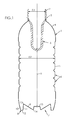
- FIG.1 illustrates a hot-fill container 1 suitable for being filled with a hot product (such as tea, fruit juice, or a sports drink).
- a hot product such as tea, fruit juice, or a sports drink.
- the container 1 includes an upper open cylindrical threaded upper portion or neck 2, which terminates, at a lower end thereof, in a support collar 3 of greater diameter. Below the collar 3, the container 1 includes a shoulder 4 which is connected to the collar 3 through a cylindrical upper end portion of short length.
- the container 1 has a wall portion 5 which is substantially cylindrical around a container main axis X.
- the wall portion 5 may, as depicted on FIG.1 and 2 , include annular stiffening ribs 6 capable of resisting stresses which would otherwise tend to make the wall portion 5 oval when viewed in a horizontal section (such a deformation is standard and called ovalization).
- the neck 2 has an outer diameter (taken between the threads) referenced D1 and the wall portion 5 has an overall diameter referenced D2.
- the container 1 has a base 7 which closes the container 1 and allows the container 1 to be put on a planar surface such as a table.
- the container base 7 includes a standing ring 8, which is a high standing ring as it will be explained later, and a central outwardly-inclined invertible diaphragm 9 which is capable of being forcedly (e.g. mechanically) pushed upwards (i.e. inwards with respect of the container 1) after the container 1 has been filled with a product, capped and cooled down, in order to compensate for the vacuum generated by the cooling of the product.
- a standing ring 8 which is a high standing ring as it will be explained later
- a central outwardly-inclined invertible diaphragm 9 which is capable of being forcedly (e.g. mechanically) pushed upwards (i.e. inwards with respect of the container 1) after the container 1 has been filled with a product, capped and cooled down, in order to compensate for the vacuum generated by the cooling of the product.
- the standing ring 8 connects to the wall portion 5 of the container at a lower end portion 10 thereof, an inner portion 11 and a support flange 12.
- the inner portion 11 connects the support flange 12 to the diaphragm 9.
- the lower end portion 10 of the wall portion 5 has, when viewed in transversal section as shown on FIG.3 , the shape of an arch with a concavity turned inward with respect of the container 1, whereby the outer diameter, referenced D3, of the support flange 12 is smaller than the overall diameter D2 of the wall portion 5.
- the inner portion 11 has the shape of a frustum of a cone and, when viewed in transversal section as shown on FIG.3 , inclines inwardly with respect of the container 1, with a draft angle.
- the cone shape of the inner portion 11 provides a vault stiffening and locking function to the diaphragm 9 in its inverted position (in dotted line on FIG.3 ), whereby the restriction of diameter of the inner portion 11 at its junction with the diaphragm 9 prevents the latter to articulate back from its inverted position with respect of the inner portion 11. As a result, re-inversion of the diaphragm 9 back to its initial position (in continuous line on FIG.3 ) under the mere hydrostatic pressure of the content of the container is prevented.
- the inner portion 11 has an axial extension which is important with respect of the outer diameter D3 of the support flange, hence the expression "high standing ring” to name the standing ring 8. More specifically, the axial extension (or height) of the inner portion 11, with reference H4, is greater than 1/10 of the outer diameter D3 of the support flange 12, and preferably comprised between 1/10 and 1/5 of the outer diameter D3 of the support flange 12: D ⁇ 3 10 ⁇ H ⁇ 1 ⁇ D ⁇ 3 5
- the height H4 of the inner portion 11 is of about 1/6 of the outer diameter D3 of the support flange 12: H ⁇ 4 ⁇ D ⁇ 3 6
- the support flange 12 has a radial extension or width, noted W4, which is small with respect of the outer diameter D3 of the support flange 12. More specifically, the width W4 of the support flange 12 is comprised between 5% and 10% - and preferably of about 6% - of the outer diameter D3 of the support flange 12: 0.05 ⁇ D ⁇ 3 ⁇ W ⁇ 4 ⁇ 0.1 ⁇ D ⁇ 3 and, preferably: W ⁇ 4 ⁇ 0.06 ⁇ D ⁇ 3
- the width W4 of the support flange 12 is also preferably in a ratio with the height H4 of the inner portion 11 comprised between 1/5 and 1/3, and preferably of about 1/4: H ⁇ 4 5 ⁇ W ⁇ 4 ⁇ H ⁇ 4 3 and preferably: W ⁇ 4 ⁇ H ⁇ 4 4
- the support flange 12 does not quite extend in a plane perpendicular to the container axis but is in the shape of a frustum of a cone and shows an inward inclination A1 when shown in the transversal section of FIG.1 , of a small angle with respect of a plane perpendicular to the container axis X.
- the invertible diaphragm 9 extends both inwards and downwards, from a outer edge 13 having a sharp apex where the diaphragm 9 connects to an upper end of the inner portion 11 of the high standing ring 8, down to a smoother inner edge 14 where the diaphragm 9 connects to a central upwardly protruding recess 15.
- the radial extension or width, denoted W5, of the diaphragm 9, is comprised between 50% and 80% - and preferably of about 60% - of the outer radius, denoted R3, of the support flange 12 (where R3 is half D3): 0.5 ⁇ R ⁇ 3 ⁇ W ⁇ 5 ⁇ 0.8 ⁇ R ⁇ 3 and, preferably: W ⁇ 5 ⁇ 0.6 ⁇ R ⁇ 3
- the axial extension, or height, denoted H5 is such that the inner edge of the diaphragm extends slightly above a standing plane perpendicular to the container axis X and defined by an outer edge of the high standing ring 8.
- the height H5 of the diaphragm 9 is slightly lower than the height H4 of the high standing ring 8.
- the height H5 of the diaphragm 9 is greater than 85% - and preferably of about 90% - of the height H4 of the standing ring 8: H ⁇ 5 ⁇ 0.85 ⁇ H ⁇ 4 and, preferably: H ⁇ 5 ⁇ 0.9 ⁇ H ⁇ 4
- FIG.4 and FIG.5 there is shown in more details a preform 16 from which the container 1 disclosed hereinbefore is formed.
- the preform 16 is made by injection or compression molding from a single plastic material, preferably PET.
- the preform 16 comprises the same neck 2 (which is not subjected to variations during the blowing of the container) as the container 1, which also terminates, at the lower end thereof, with the support collar 3.
- the preform 16 has a body 17 which includes a wall 18 and, at a lower end of the wall 18, a closed bottom 19 which terminates the preform 16 at a lower side opposite the neck 2.
- the length of the preform body 17 (i.e. below the collar 3), is denoted L.
- the preform 16 In its wall 18 and bottom 19, the preform 16 has an outer surface 20 and an inner surface 21.
- the wall 18 of the preform 16 is comprised of a main segment 22 of substantially cylindrical shape, an upper end segment 23 which terminates the main segment 22 upwardly and connects to the collar 3, and a lower end segment 24 which terminates the main segment 22 downwardly and connects to the bottom 19.
- the main segment 22 forms the wall portion 5 of the container 1; the upper end segment 23 forms the shoulder 4 of the container 1; the lower end segment 24 forms the high standing ring 8 of the container 1; and the bottom 19 of the preform 16 forms the invertible diaphragm 9 and central protruding recess 15, as shown by the arrows on FIG.7 .
- the overall diameter of the main segment 22, taken at its junction with the upper end segment 23 is denoted D6.
- the preform 16 corresponds to a container 1 of small capacity (i.e. less than 1 I, such as 0.5 or 0.6 I)
- the overall diameter D6 of the main segment 22 is smaller than the diameter D1 of the neck 2.
- the preform corresponds to a container of greater capacity (i.e. more than 1 I, such as 1.5 I or 2 I)
- this relationship may be reversed.
- the upper end segment 23 has the shape of a horn and smoothly connects the main segment 22 at diameter D6 to the collar 3 at diameter D1.
- the wall thickness of the preform 16 in the upper end segment 23 increases from a value T1 immediately below the collar 3, where it corresponds to the wall thickness of the preform 16 in the neck 2 (excluding the thread), to a value T2 at the junction with the main segment, where T1 is lower than T2, and preferably lower than half T2: T ⁇ 1 ⁇ T ⁇ 2 and preferably: T ⁇ 1 ⁇ 0.5 ⁇ T ⁇ 2
- the main segment 22 is in the shape of a frustum of a cone with a small draft angle B1 on the outer surface 20 and a small draft angle B2 on the inner surface 21, both angles B1 and B2 being lower than 2°, and preferably: B ⁇ 1 ⁇ B ⁇ 2 ⁇ 2 ⁇ °
- B1 is smaller than 1°, and preferably of about 0.6°. Also in a preferred embodiment, B2 is smaller than 1.5°, and preferably of about 1.3°.
- the length, taken axially and denoted L1, of the main segment 22, is comprised between 60% and 70% - and preferably between 65% and 70% - of the length L of the preform 16: 0 , 6 ⁇ L ⁇ L ⁇ 1 ⁇ 0.7 ⁇ L and preferably: 0 , 65 ⁇ L ⁇ L ⁇ 1 ⁇ 0.7 ⁇ L
- the preform wall thickness may be substantially constant along the main segment 22, in a preferred embodiment, the preform wall thickness, as measured perpendicularly to the preform axis X, slightly (and linearly) increases from the value T2 at the junction of the upper end segment 23 and the main segment 22, to a value T3 at the junction of the main segment 22 and the lower end segment 24: T ⁇ 2 ⁇ T ⁇ 3
- the material distribution in the upper end segment 23 and main segment 22 is calculated to provide substantially constant thickness of the container 1 in the shoulder 4 and wall portion 5.
- the thickness increase in the upper end segment 23 allows for a sufficient thickness of the material in the container shoulder 4, since the material located immediately below the collar 3 is less stretched (mostly in the radial or hoop direction) than the material located at the junction between the upper end segment 23 and the main segment 22 of the preform 16.
- the thickness increase in the main segment 22 allows for a sufficient thickness of the material in the wall portion 5 of the container 1, since the material located at the junction between the main segment 22 and the upper end segment is less stretched (both in the axial or length direction and in the radial or hoop direction).
- the lower end segment 24 has an upper section 25 of increasing wall thickness, adjacent the main segment 22, and a lower section 26 of substantially constant wall thickness, adjacent the bottom 19.
- the preform 16 has a wall thickness, denoted T4, the value of which is therefore greater than the value T3 of the wall thickness of the preform 16 at the junction of the main segment 22 and lower end segment 24.
- T4 is 5% to 15% greater than T3, and for example of about 10% greater than T3: T ⁇ 4 ⁇ T ⁇ 3 and, preferably: 1.05 ⁇ T ⁇ 3 ⁇ T ⁇ 4 ⁇ 1.15 ⁇ T ⁇ 3 and, for example: T ⁇ 4 ⁇ 1.1 ⁇ T ⁇ 3
- the increased wall thickness of the preform 16 in the lower end segment 24 allows for reinforcing the lower end portion 10 and the support flange 12, more specifically in the vicinity of the junction between the lower end portion 10 and the support flange 12, where rigidity is required on the one hand to facilitate the inversion process and, on the other hand, to provide good stability of the container 1 both during mass handling or storing operations, and during individual normal use of the container 1 where it is stored vertically standing on a planar surface such as a table or a refrigerator shelf.
- the length, taken axially and denoted L2, of the lower end segment 24, is comprised between 30% and 40% - and preferably between 30% and 35% - of the length L1 of the main segment 22.
- L2 is about 33% of L1: 0 , 3 ⁇ L ⁇ 1 ⁇ L ⁇ 2 ⁇ 0.4 ⁇ L ⁇ 1 and preferably: 0 , 6 ⁇ L ⁇ 1 ⁇ L ⁇ 2 ⁇ 0.35 ⁇ L ⁇ 1 and, for example: L ⁇ 2 ⁇ 0.33 ⁇ L ⁇ 1
- the preform 16 is provided with a rounded upstanding centering index 27 protruding inwardly from the inner surface 21 of the preform 16 in the axis X thereof.
- the preform 16 is injection molded
- the preform 16 is provided with a downwardly projecting central protrusion 28 which corresponds to the counter print of an injection gate formed in the mold in which the preform 16 was injection molded.
- the bottom of the preform 16 has a central region 29 in the form of a spherical dome, the center C of curvature of which is located on the preform axis X.
- the outer surface 20 and the inner surface 21 of the preform 16 are preferably both spherical with common center of curvature C.
- the preform 16 has a wall thickness, denoted T5, as taken radially from the center C of curvature, which is substantially constant.
- the bottom of the preform 16 is also provided with a peripheral region 30 which is located below the lower end segment 24 and makes junction with the central region 29.
- the peripheral region 30 is of decreasing wall thickness as taken radially from the center C of curvature of the central region 29, such that the wall thickness T5 of the preform 16 in the central region 29 of the bottom 19 is smaller than the wall thickness T4 of the lower end segment 24.
- the wall thickness T5 of the preform 16 in the central region 29 is comprised between 50% and 80% (and preferably lower than 70%, and for example of about 65%) of the wall thickness T4 of the lower end segment 24: 0.5 ⁇ T ⁇ 4 ⁇ T ⁇ 5 ⁇ 0.8 ⁇ T ⁇ 4 preferably: 0.5 ⁇ T ⁇ 4 ⁇ T ⁇ 5 ⁇ 0.7 ⁇ T ⁇ 4 and, for example: T ⁇ 5 ⁇ 0.65 ⁇ T ⁇ 4
- the decreased wall thickness of the peripheral region 30, and the comparatively smaller (and constant) wall thickness in the central region 29 of the preform bottom 19 allows for a better printing of the invertible diaphragm 9, and a reduced thickness of the material in the invertible diaphragm 9, thereby facilitating inversion thereof, as will be disclosed hereinafter.
- the manufacturing of the hot-fill container 1 from the preform 16 is achieved through a blow molding unit 31 including a blow mold 32 and a stretch rod 33, as depicted on FIG.6 and FIG.7 .
- the blow mold 32 has sidewalls 34A, 34B, including heating means, not illustrated (such as holes for the circulation of a heating fluid such as hot water or hot oil, or electric radiators received within the sidewalls 34A, 34B), for heating the sidewalls 34A, 34B at a predetermined temperature much greater than the average environment temperature and which, in a preferred embodiment, is of about 80-180°C.
- heating means not illustrated (such as holes for the circulation of a heating fluid such as hot water or hot oil, or electric radiators received within the sidewalls 34A, 34B), for heating the sidewalls 34A, 34B at a predetermined temperature much greater than the average environment temperature and which, in a preferred embodiment, is of about 80-180°C.
- the sidewalls 34A, 34B together define at least part of a molding cavity 35 for receiving the preform 16 and form a counter print of the wall portion 5, including the lower end portion 10 and shoulder 4 of the container 1.
- the blow mold 32 also has a mold base 36, which has an upper surface 37 forming a counter print of the container base 7 including the support flange 12, the inner portion 11, the diaphragm 9 and the central protruding recess 15.
- the sidewalls 34A, 34B, together with the mold base 36, define the whole molding cavity 35 of the container 1.
- the mold base 36 is movable with respect of the sidewalls 34A, 34B between a retracted position ( FIG.6 ) in which the upper surface 37 extends below the container base 7 to be blow molded, and a raised position ( FIG.7 ) in which the upper surface 37 closes the cavity 35 and extends at the exact place of the container base 7 to be blow molded.
- This provides an over stretching of the material during the blow molding, whereby the material of the preform 16 is first stretched beyond the final position of the container base 7, in the retracted position of the mold base 36, and then the mold base 36 is moved to its raised position in order to push the stretched material up to form the final shape of the container base 7.
- the centering index 27 is received within a corresponding recess 38 formed axially at a lower end tip of a stretch rod 33. This ensures a proper centering of the preform 16 until it reaches the mold base 36.
- the central outward protrusion 28 is received within a central recess 39 formed axially in a mold base 36. This ensures a proper centering of the container base 7 during the pushing up thereof, through the displacement of the mold base 36 from its retracted position to its raised position.
- the preform 16 is subjected to a length stretch ratio comprised between 3.4 and 3.9, and a hoop stretch ratio comprised between 3.5 and 3.9.
- the length stretch ratio is the ratio between the developed length of an average line 40 between the outer surface 20 and the inner surface 21 of the preform 16 taken along the body 17, i.e. from immediately below the collar 3 to the center of the bottom 19, in an axial sectional plane as depicted on FIG.1 , and the developed length of the container 1 taken from immediately below the collar 3 to the center of the base 7, in a same axial sectional plane as depicted on FIG.1 .
- the hoop stretch ratio is the ratio between the average diameter D7 of the main segment 22 (i.e. at about half of the length thereof), taken at the average line 40 ) and the overall diameter D2 of the wall portion 5 of the container 1.
- the length stretch ratio is comprised between 3.6 and 3.8. Also in a preferred embodiment, the hoop stretch ratio is comprised between 3.7 and 3.8.
- Such stretch ratios allows for a better printing of the container wall portion 5 and base during the blow molding. More specifically, this facilitates the printing of stiffening ribs 6 on the wall portion 5 of the container 1, which provide rigidity of the wall portion 5 against deformations due to a vacuum inside the container 1 and confine most of the container 1 deformation onto the container base 7.
- the mold base 36 is illustrated in further details on FIG.8 and FIG.9 .
- the mold base 36 comprises a cylindrical piston 41 by which the mold base 36 is capable of being axially moved and guided in a corresponding bore 42 in the bottom of the sidewalls 34A, 34B.
- the piston 41 terminates by the upper surface 37 forming a counter print of the container base 7, including the support flange 12, the inner portion 11 of the high standing ring 8, and also the diaphragm 9 and central protruding recess 15.
- the upper surface 37 includes an annular peripheral face 43 corresponding to the annular support flange 12 of the container base 7.
- This peripheral face 43 does not quite extend in a plane perpendicular to the base mold axis (which is substantially identical to the preform and container axis X) but is in the shape of a frustum of a cone and shows an inward inclination when shown in the transversal section of FIG.9 , of a small angle A1 comprised between 1° and 10°, preferably between 2° and 5° - and for example of about 3° - with respect of a plane perpendicular to the base mold axis.
- the upper surface 37 also includes a frusto-conical outer face 44 corresponding to the inner portion 11 of the high standing ring 8.
- the outer face 44 protrudes upwardly from an inner edge of the annular peripheral face 43, up to a sharp apex 45 corresponding to the outer edge 13 at the junction between the inner portion 11 and the diaphragm 9.
- the outer face 44 defines a draft angle A2 with respect of a vertical line parallel to the base mold axis comprised between 1° and 10°, preferably between 3° and 6°, and for example of about 4.5°.
- the upper surface 37 of the mold base 36 further includes a frusto-conical downwardly inclined inner face 46 corresponding to the invertible diaphragm 9.
- the inner face 46 extends from the apex 45 down to an annular inner edge 47 where it connects to a central uprising push-up 48 corresponding to the central recess 15 in the container base 7.
- the apex 45 is sharp in that it has a radius of curvature, denoted R, of less than or equal to 1.5 mm. In a preferred embodiment, the radius R of curvature of the apex 45 is less than or equal to 0.25 mm. The apex 45 may also have no measurable radius of curvature, i.e. the radius of curvature is less than or equal to 0.1 mm.
- This provides a sharp junction between the inner portion 11 and the diaphragm 9 in the container base 7, allowing for both a better inward inversion of the diaphragm 9 wherein the sharp apex of the outer edge 13 at the junction between the inner portion 11 and the diaphragm 9 forms a punctual (when view in axial section) hinge therebetween, and a better rigidity of the container base 7 after inversion.
- Part of the mold base 36 may be lathe worked, in particular to obtain the sharp apex 45.
- angle A3 when shown in an axial sectional plane such as on FIG.9 , comprised between 50° and 70°, and preferably comprised between 60° and 65°. In a preferred embodiment, angle A3 is of about 63°.
- the extraction volume EV is also maximized due to the inner edge 47 located close to a peripheral plane P (corresponding to the standing plane of the container 1 ) defined by the outer edge of the peripheral face 43, whereby the inner edge 47 is spaced from the peripheral plane with a clearance CL comprised between 1 mm and 5 mm, and preferably of about 2 mm.
- a clearance CL comprised between 1 mm and 5 mm, and preferably of about 2 mm.
- the push-up 48 is star-shaped is transversal section and comprises a series of recesses 49 (five in the depicted example) which, by counter printing during the blow molding of the container 1, form convex reinforcing ribs 50 in the central recess 15 of the container base 7, thereby stiffening the central recess 15 and preventing inversion thereof under the combined effects of hydrostatic pressure and temperature of the content.
- Inversion of the diaphragm 9 is preferably achieved mechanically by means of a mandrel which has a top apex capable of being received into the central recess 15 and which, after filling, capping and cooling down of the container 1, is moved upwards whereas the container 1 is held tight.
- the diaphragm 9 deforms and articulates around the sharp junction with the inner portion 11 which is slightly bent outwards, until the diaphragm 9 upwardly inverts towards its final position depicted in dotted line on FIG.3 .
- the inner portion 11 of the high standing ring 8 then bends back to its initial position where it forms an arch capable of standing buckling and bending constraints applied by the diaphragm 9 under hydrostatic pressure of the content.
Landscapes
- Engineering & Computer Science (AREA)
- Mechanical Engineering (AREA)
- Manufacturing & Machinery (AREA)
- Physics & Mathematics (AREA)
- Thermal Sciences (AREA)
- Ceramic Engineering (AREA)
- Geometry (AREA)
- Blow-Moulding Or Thermoforming Of Plastics Or The Like (AREA)
- Containers Having Bodies Formed In One Piece (AREA)
Abstract
- heating the preform (16) at a temperature greater than the glass transition temperature of the plastic;
- introducing the such heated preform (16) within a mold (32) provided with a mold base (36) and sidewalls (34A, 34B), which sidewalls are heated at a predetermined temperature;
- blow molding the preform (16) to form the container (1) for subsequent hot-fill applications;
wherein:
- the wall of said preform (16) has a lower end segment (24) of increased thickness and the bottom (19) has a thickness lower than the lower end segment (24),
- the preform (16) is subjected to a length stretch ratio comprised between 3.4 and 3.9, and a hoop stretch ratio comprised between 3.5 and 3.9.
Description
- The invention generally relates to the manufacturing of containers, such as bottles, which are produced by blow molding or stretch-blow molding from preforms made of plastic (mostly thermoplastic, e.g. PET) material. More specifically, the invention relates to the manufacturing of hot-fill containers, i.e. containers ready to be filled by liquids at a high temperature (generally higher than the glass transition temperature of the material in which the container is made).
- A conventional preform, which is generally injected molded but might also be compression molded, is comprised of an open cylindrical threaded upper portion or neck, which terminates at a lower end in an annular protrusion, forming a support collar (used to carry the perform and the container at different steps of the manufacturing and packaging processes), a wall portion of generally cylindrical shape which extends below the support collar, and a closed rounded bottom portion which extends below the wall portion.
- During a conventional blow molding process, the preform undergoes both an axial (or length) stretch and a radial (or hoop) stretch to form the container. The combined length and hoop stretch provides molecular bi-orientation to the material, whereby the final container has good structural rigidity, generally sufficient to resist mechanical stresses due to the hydrostatic pressure of the liquid therein.
- However, bi-orientation induces residual stresses in the material. Such residual stresses are released during hot-filling (particularly with a liquid having a temperature higher than the glass transition temperature of the material), causing a deformation of the container that could make it unsuitable for use - and hence for sale.
- To decrease deformation of the container during hot-filling, it is known to run the blow molding within a mold provided with sidewalls and a mold base, the sidewalls being heated at a predetermined temperature, and to complete the blowing through a thermal treatment called heat set, by which the container is held in contact with the sidewalls at a predetermined temperature between 80°C and 180°C for a predetermined time (generally several seconds).
- Generally, two sidewalls are present. They are usually named "half-molds". They can be moved away from one another and from the mold base for allowing either the introduction of a preform or the removal of the finished container. The sidewalls are placed in close contact together and with the mold base during the blow molding step.
- However, heat setting solves only part of the problems of deformation of a hot-fill container. Indeed, while cooling, the liquid and the air above the liquid in the capped container undergo a decrease in volume that tends to make the container retract.
- Several solutions have been considered for decreasing the visible effects of such retraction. These solutions generally concern the shape of the container.
- For example, it has been proposed to equip the body of the container with deformable side panels that bend inwards under the effect of the retraction and bend back outwards when the container is opened. Such containers must be handled with care by the user because of the flexibility of the body, which may result in accidental spraying.
- It has also been proposed to provide the container with a base portion capable of withstanding the various stresses and strains applied to the container, see e.g.
U.S. Pat. No. 6,896,147 (assigned to Graham). - More recently, it has been proposed to give the bottom of the container a special shape capable of absorbing at least part of the deformation due to retraction whereas the body of the container is provided with a rigid (i.e. resistant to hot-fill deformation) structure, see e.g.
U.S. Pat. No. 7,451,886 (assigned to Amcor). - Deformable bottoms take advantage over deformable side panels in that from the user's point of view the container feels rigid, whereby the risk of spraying during handling is considerably lowered. However, the amount of vacuum absorbed by deformation of the deformable bottom may be insufficient and result in a deformation of the body which may take an oval shape (such a well-known deformation is called "ovalization" by the skilled technicians).
-
U.S. Pat. Appl. No. 2008/0047964 (Denner et al , assigned to CO2PAC) discloses a container comprising a pressure panel located in the bottom portion of the container. The pressure panel is movable between an outwardly-inclined position and an inwardly-inclined position to compensate for a change of pressure inside the container. In order to alleviate all or a portion of the vacuum forces within the container, the pressure panel is moved from the outwardly-inclined position by a mechanical pusher in order to force the pressure panel into the inwardly-inclined position. The inversion of the pressure panel from the outwardly-inclined position to the inwardly-inclined position reduces the internal volume of the container. - Denner also provides an exemplary method of blow molding such a plastic container, which includes enclosing a softened polymer material such as PET within a blow mold having side wall portions and a base mold portion movable with respect of the side mold portions in the vertical direction between a retracted position and an extended position. The base mold portion is displaced upwardly into the mold cavity to form a transverse pressure panel deeply set within the base portion of the container.
- Although Denner provides a solution which in theory alleviates the drawbacks of previous solutions with deformable bottoms in that it maximizes the amount of vacuum compensation, Denner fails to disclose the whole process allowing to form the target container, despite the mere description of the deep setting of the pressure panel by means of a movable base mold portion, the use of which, as may be noted, is already known, see e.g.
U.S. Pat. No. 4,035,455 (Rosenkranz et al ). In particular, Denner fails to point out specific structural features of the preform and specific features of the process, which should be used to allow the target container to be correctly formed, with a proper distribution of the material throughout the container. - It is a main purpose of the present invention to alleviate the hereabove mentioned drawbacks of the prior art.
- It is an object of the invention to propose a full method of manufacturing a hot-fill container provided with a high standing ring and a central outwardly-inclined invertible diaphragm.
- It is another object of the invention to enhance performances of such a hot-fill container.
- It is yet another object of the invention to increase stability of such a hot-fill container while facilitating inversion of the invertible diaphragm.
- It is therefore provided a method of manufacturing a hot-fill container from a plastic preform by means of blow molding said preform, wherein said container is provided with a base including a high standing ring and a central outwardly-inclined invertible diaphragm, wherein said preform has an open neck, a wall and a closed bottom, said method comprising the steps of:
- heating the preform at a temperature greater than the glass transition temperature of the plastic;
- introducing the such heated preform within a mold provided with a mold base and sidewalls, which sidewalls are heated at a predetermined temperature;
- blow molding the preform to form the container for subsequent hot-fill applications;
wherein: - the wall of said preform has a main segment of substantially cylindrical shape and a lower end segment of increased thickness adjacent the bottom, whereby said lower end segment is stretched to form the high standing ring of the container, and the bottom has a thickness lower than the lower end segment whereby the bottom is stretched to form the invertible diaphragm of the container,
- the preform is subjected to a length stretch ratio comprised between 3.4 and 3.9, and a hoop stretch ratio comprised between 3.5 and 3.9.
- According to various embodiments, taken either separately or in combination:
- the stretch ratio is comprised between 3.6 and 3.8;
- the hoop stretch ratio is comprised between 3.7 and 3.8;
- the lower end segment of the preform has a wall thickness of about 10% greater than a wall thickness of the main segment;
- the bottom has a central region with a substantially constant wall thickness;
- the central region has a wall thickness lower than 80% of the wall thickness in the lower end segment;
- the central region has a wall thickness lower than 70% of the wall thickness in the lower end segment;
- the central region has a wall thickness of about 65% of the wall thickness in the lower end segment;
- preform is axially stretched by a stretch rod;
- the preform is provided with a centering index capable of being received in a recess formed at a lower end tip of the stretch rod.
- The above and other objects and advantages of the invention will become apparent from the detailed description of preferred embodiments, considered in conjunction with the accompanying drawings.
- In the drawings:
-
FIG.1 is a realistic sectional view showing both a preform and a resulting hot-fill container formed therefrom; -
FIG.2 is a realistic bottom perspective view showing the container ofFIG.1 ; -
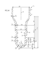
FIG.3 is a realistic enlarged fragmentary sectional view showing a detail of the container ofFIG.1 through the base of the container; -
FIG.4 is a realistic enlarged sectional view showing the preform ofFIG.1 ; -
FIG.5 is a realistic enlarged fragmentary sectional view showing a detail of the preform ofFIG.4 , in the vicinity of a bottom of the preform; -
FIG.6 is a realistic sectional view of a stretch blow molding unit including a mold with a movable base mold for manufacturing a hot-fill container, showing a preform from which the container is to be formed; -
FIG.7 is a realistic sectional view of the stretch-blow molding unit ofFIG.6 , further showing the container formed therein from the preform (also shown in dotted line); -
FIG.8 is a realistic perspective view of a base mold for a molding unit ofFIG.6 ; -
FIG.9 is a realistic enlarged fragmentary sectional view showing a detail of the base mold ofFIG.8 . -
FIG.1 illustrates a hot-fill container 1 suitable for being filled with a hot product (such as tea, fruit juice, or a sports drink). - The container 1 includes an upper open cylindrical threaded upper portion or
neck 2, which terminates, at a lower end thereof, in asupport collar 3 of greater diameter. Below thecollar 3, the container 1 includes ashoulder 4 which is connected to thecollar 3 through a cylindrical upper end portion of short length. - Below the
shoulder 4, the container 1 has awall portion 5 which is substantially cylindrical around a container main axis X. Thewall portion 5 may, as depicted onFIG.1 and2 , includeannular stiffening ribs 6 capable of resisting stresses which would otherwise tend to make thewall portion 5 oval when viewed in a horizontal section (such a deformation is standard and called ovalization). - The
neck 2 has an outer diameter (taken between the threads) referenced D1 and thewall portion 5 has an overall diameter referenced D2. - At a lower end of the
wall portion 5, the container 1 has abase 7 which closes the container 1 and allows the container 1 to be put on a planar surface such as a table. - The
container base 7 includes a standingring 8, which is a high standing ring as it will be explained later, and a central outwardly-inclined invertible diaphragm 9 which is capable of being forcedly (e.g. mechanically) pushed upwards (i.e. inwards with respect of the container 1) after the container 1 has been filled with a product, capped and cooled down, in order to compensate for the vacuum generated by the cooling of the product. - The standing
ring 8 connects to thewall portion 5 of the container at alower end portion 10 thereof, aninner portion 11 and asupport flange 12. Theinner portion 11 connects thesupport flange 12 to the diaphragm 9. - In a preferred embodiment, the
lower end portion 10 of thewall portion 5 has, when viewed in transversal section as shown onFIG.3 , the shape of an arch with a concavity turned inward with respect of the container 1, whereby the outer diameter, referenced D3, of thesupport flange 12 is smaller than the overall diameter D2 of thewall portion 5. - The
inner portion 11 has the shape of a frustum of a cone and, when viewed in transversal section as shown onFIG.3 , inclines inwardly with respect of the container 1, with a draft angle. - The cone shape of the
inner portion 11 provides a vault stiffening and locking function to the diaphragm 9 in its inverted position (in dotted line onFIG.3 ), whereby the restriction of diameter of theinner portion 11 at its junction with the diaphragm 9 prevents the latter to articulate back from its inverted position with respect of theinner portion 11. As a result, re-inversion of the diaphragm 9 back to its initial position (in continuous line onFIG.3 ) under the mere hydrostatic pressure of the content of the container is prevented. - The
inner portion 11 has an axial extension which is important with respect of the outer diameter D3 of the support flange, hence the expression "high standing ring" to name the standingring 8. More specifically, the axial extension (or height) of theinner portion 11, with reference H4, is greater than 1/10 of the outer diameter D3 of thesupport flange 12, and preferably comprised between 1/10 and 1/5 of the outer diameter D3 of the support flange 12:
- In one preferred embodiment, which corresponds to the illustration of
FIG.3 , the height H4 of theinner portion 11 is of about 1/6 of the outer diameter D3 of the support flange 12:
- The
support flange 12 has a radial extension or width, noted W4, which is small with respect of the outer diameter D3 of thesupport flange 12. More specifically, the width W4 of thesupport flange 12 is comprised between 5% and 10% - and preferably of about 6% - of the outer diameter D3 of the support flange 12:
and, preferably:
- The width W4 of the
support flange 12 is also preferably in a ratio with the height H4 of theinner portion 11 comprised between 1/5 and 1/3, and preferably of about 1/4:
and preferably:
- In addition, in the just-blown non-filled configuration of the container 1 as depicted on
FIG.1 and in continuous line onFIG.3 , thesupport flange 12 does not quite extend in a plane perpendicular to the container axis but is in the shape of a frustum of a cone and shows an inward inclination A1 when shown in the transversal section ofFIG.1 , of a small angle with respect of a plane perpendicular to the container axis X. This provides a spring and absorbing effect under the hydrostatic pressure on the diaphragm 9 in its upwardly inverted position (in dotted lines onFIG.3 ), whereby pressure on the diaphragm 9 results in thesupport flange 12 pivoting and coming into abutment with a planar supporting surface instead of inversion of the diaphragm 9 back to its initial position (in continuous line onFIG.3 ). - In the just-blown non-filled configuration of the container 1 as depicted on
FIG.1 and in continuous line onFIG.3 , the invertible diaphragm 9 extends both inwards and downwards, from aouter edge 13 having a sharp apex where the diaphragm 9 connects to an upper end of theinner portion 11 of thehigh standing ring 8, down to a smootherinner edge 14 where the diaphragm 9 connects to a central upwardly protrudingrecess 15. - In a preferred embodiment, the radial extension or width, denoted W5, of the diaphragm 9, is comprised between 50% and 80% - and preferably of about 60% - of the outer radius, denoted R3, of the support flange 12 (where R3 is half D3):

and, preferably:
- In addition, the axial extension, or height, denoted H5, of the diaphragm, is such that the inner edge of the diaphragm extends slightly above a standing plane perpendicular to the container axis X and defined by an outer edge of the
high standing ring 8. - In other words, the height H5 of the diaphragm 9 is slightly lower than the height H4 of the
high standing ring 8. In a preferred embodiment, the height H5 of the diaphragm 9 is greater than 85% - and preferably of about 90% - of the height H4 of the standing ring 8:
and, preferably:
- On
FIG.4 andFIG.5 , there is shown in more details apreform 16 from which the container 1 disclosed hereinbefore is formed. Thepreform 16 is made by injection or compression molding from a single plastic material, preferably PET. - The
preform 16 comprises the same neck 2 (which is not subjected to variations during the blowing of the container) as the container 1, which also terminates, at the lower end thereof, with thesupport collar 3. - Below the
collar 3, thepreform 16 has abody 17 which includes awall 18 and, at a lower end of thewall 18, a closed bottom 19 which terminates thepreform 16 at a lower side opposite theneck 2. The length of the preform body 17 (i.e. below the collar 3), is denoted L. - In its
wall 18 and bottom 19, thepreform 16 has anouter surface 20 and aninner surface 21. - As depicted on
FIG.4 , thewall 18 of thepreform 16 is comprised of amain segment 22 of substantially cylindrical shape, anupper end segment 23 which terminates themain segment 22 upwardly and connects to thecollar 3, and alower end segment 24 which terminates themain segment 22 downwardly and connects to the bottom 19. - During the blow molding of the container 1, the
main segment 22 forms thewall portion 5 of the container 1; theupper end segment 23 forms theshoulder 4 of the container 1; thelower end segment 24 forms thehigh standing ring 8 of the container 1; and the bottom 19 of thepreform 16 forms the invertible diaphragm 9 and central protrudingrecess 15, as shown by the arrows onFIG.7 . - The overall diameter of the
main segment 22, taken at its junction with theupper end segment 23 is denoted D6. - In the depicted embodiment wherein the
preform 16 corresponds to a container 1 of small capacity (i.e. less than 1 I, such as 0.5 or 0.6 I), the overall diameter D6 of themain segment 22 is smaller than the diameter D1 of theneck 2. In an alternate embodiment in which the preform corresponds to a container of greater capacity (i.e. more than 1 I, such as 1.5 I or 2 I), this relationship may be reversed. - In a preferred embodiment corresponding to the illustrated example, the
upper end segment 23 has the shape of a horn and smoothly connects themain segment 22 at diameter D6 to thecollar 3 at diameter D1. As may be seen onFIG.4 , the wall thickness of thepreform 16 in theupper end segment 23, as measured perpendicularly to the preform axis X (which is identical to the subsequent container axis X), increases from a value T1 immediately below thecollar 3, where it corresponds to the wall thickness of thepreform 16 in the neck 2 (excluding the thread), to a value T2 at the junction with the main segment, where T1 is lower than T2, and preferably lower than half T2:
and preferably:
- In the illustrated preferred embodiment, the
main segment 22 is in the shape of a frustum of a cone with a small draft angle B1 on theouter surface 20 and a small draft angle B2 on theinner surface 21, both angles B1 and B2 being lower than 2°, and preferably:
- In a preferred embodiment, B1 is smaller than 1°, and preferably of about 0.6°. Also in a preferred embodiment, B2 is smaller than 1.5°, and preferably of about 1.3°.
- In a preferred embodiment, the length, taken axially and denoted L1, of the
main segment 22, is comprised between 60% and 70% - and preferably between 65% and 70% - of the length L of the preform 16:
and preferably:
- Although the preform wall thickness may be substantially constant along the
main segment 22, in a preferred embodiment, the preform wall thickness, as measured perpendicularly to the preform axis X, slightly (and linearly) increases from the value T2 at the junction of theupper end segment 23 and themain segment 22, to a value T3 at the junction of themain segment 22 and the lower end segment 24:
- The material distribution in the
upper end segment 23 andmain segment 22 is calculated to provide substantially constant thickness of the container 1 in theshoulder 4 andwall portion 5. - The thickness increase in the
upper end segment 23 allows for a sufficient thickness of the material in thecontainer shoulder 4, since the material located immediately below thecollar 3 is less stretched (mostly in the radial or hoop direction) than the material located at the junction between theupper end segment 23 and themain segment 22 of thepreform 16. Similarly, the thickness increase in themain segment 22 allows for a sufficient thickness of the material in thewall portion 5 of the container 1, since the material located at the junction between themain segment 22 and the upper end segment is less stretched (both in the axial or length direction and in the radial or hoop direction). - In the illustrated preferred embodiment, the
lower end segment 24 has anupper section 25 of increasing wall thickness, adjacent themain segment 22, and alower section 26 of substantially constant wall thickness, adjacent the bottom 19. In thelower section 26, thepreform 16 has a wall thickness, denoted T4, the value of which is therefore greater than the value T3 of the wall thickness of thepreform 16 at the junction of themain segment 22 andlower end segment 24. In a preferred embodiment, T4 is 5% to 15% greater than T3, and for example of about 10% greater than T3: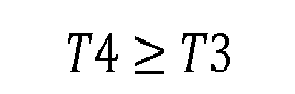
and, preferably:
and, for example: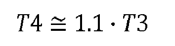
- The increased wall thickness of the
preform 16 in thelower end segment 24 allows for reinforcing thelower end portion 10 and thesupport flange 12, more specifically in the vicinity of the junction between thelower end portion 10 and thesupport flange 12, where rigidity is required on the one hand to facilitate the inversion process and, on the other hand, to provide good stability of the container 1 both during mass handling or storing operations, and during individual normal use of the container 1 where it is stored vertically standing on a planar surface such as a table or a refrigerator shelf. - In a preferred embodiment, the length, taken axially and denoted L2, of the
lower end segment 24, is comprised between 30% and 40% - and preferably between 30% and 35% - of the length L1 of themain segment 22. In the preferred depicted example, L2 is about 33% of L1:
and preferably:
and, for example:
- In a preferred embodiment illustrated on
FIG.4 , thepreform 16 is provided with a rounded upstanding centeringindex 27 protruding inwardly from theinner surface 21 of thepreform 16 in the axis X thereof. - Also in one embodiment illustrated on
FIG.4 , wherein thepreform 16 is injection molded, thepreform 16 is provided with a downwardly projectingcentral protrusion 28 which corresponds to the counter print of an injection gate formed in the mold in which thepreform 16 was injection molded. - In a preferred embodiment, the bottom of the
preform 16 has acentral region 29 in the form of a spherical dome, the center C of curvature of which is located on the preform axis X. - In the
central region 29, theouter surface 20 and theinner surface 21 of thepreform 16 are preferably both spherical with common center of curvature C. - In consequence, in the central region 29 (apart from the centering index and protrusion), the
preform 16 has a wall thickness, denoted T5, as taken radially from the center C of curvature, which is substantially constant. - In the depicted example, the bottom of the
preform 16 is also provided with aperipheral region 30 which is located below thelower end segment 24 and makes junction with thecentral region 29. Theperipheral region 30 is of decreasing wall thickness as taken radially from the center C of curvature of thecentral region 29, such that the wall thickness T5 of thepreform 16 in thecentral region 29 of the bottom 19 is smaller than the wall thickness T4 of thelower end segment 24. - In a preferred embodiment, the wall thickness T5 of the
preform 16 in thecentral region 29 is comprised between 50% and 80% (and preferably lower than 70%, and for example of about 65%) of the wall thickness T4 of the lower end segment 24:
preferably:
and, for example:
- The decreased wall thickness of the
peripheral region 30, and the comparatively smaller (and constant) wall thickness in thecentral region 29 of the preform bottom 19 allows for a better printing of the invertible diaphragm 9, and a reduced thickness of the material in the invertible diaphragm 9, thereby facilitating inversion thereof, as will be disclosed hereinafter. - The manufacturing of the hot-fill container 1 from the
preform 16 is achieved through ablow molding unit 31 including ablow mold 32 and astretch rod 33, as depicted onFIG.6 andFIG.7 . - The
blow mold 32 has sidewalls 34A, 34B, including heating means, not illustrated (such as holes for the circulation of a heating fluid such as hot water or hot oil, or electric radiators received within thesidewalls sidewalls - The
sidewalls molding cavity 35 for receiving thepreform 16 and form a counter print of thewall portion 5, including thelower end portion 10 andshoulder 4 of the container 1. - The
blow mold 32 also has amold base 36, which has anupper surface 37 forming a counter print of thecontainer base 7 including thesupport flange 12, theinner portion 11, the diaphragm 9 and the central protrudingrecess 15. Thesidewalls mold base 36, define thewhole molding cavity 35 of the container 1. - The
mold base 36 is movable with respect of the sidewalls 34A, 34B between a retracted position (FIG.6 ) in which theupper surface 37 extends below thecontainer base 7 to be blow molded, and a raised position (FIG.7 ) in which theupper surface 37 closes thecavity 35 and extends at the exact place of thecontainer base 7 to be blow molded. - This provides an over stretching of the material during the blow molding, whereby the material of the
preform 16 is first stretched beyond the final position of thecontainer base 7, in the retracted position of themold base 36, and then themold base 36 is moved to its raised position in order to push the stretched material up to form the final shape of thecontainer base 7. - Such a process allows for a better printing quality, a better material thickness, and hence a better stiffness from the
lower end portion 10 to theinner portion 11. - During the stretch blow molding of the container 1, the centering
index 27 is received within a correspondingrecess 38 formed axially at a lower end tip of astretch rod 33. This ensures a proper centering of thepreform 16 until it reaches themold base 36. - By the end of the blow molding of the container 1, the central
outward protrusion 28 is received within acentral recess 39 formed axially in amold base 36. This ensures a proper centering of thecontainer base 7 during the pushing up thereof, through the displacement of themold base 36 from its retracted position to its raised position. - During the blow molding of the container 1, the
preform 16 is subjected to a length stretch ratio comprised between 3.4 and 3.9, and a hoop stretch ratio comprised between 3.5 and 3.9. - The length stretch ratio is the ratio between the developed length of an
average line 40 between theouter surface 20 and theinner surface 21 of thepreform 16 taken along thebody 17, i.e. from immediately below thecollar 3 to the center of the bottom 19, in an axial sectional plane as depicted onFIG.1 , and the developed length of the container 1 taken from immediately below thecollar 3 to the center of thebase 7, in a same axial sectional plane as depicted onFIG.1 . - The hoop stretch ratio is the ratio between the average diameter D7 of the main segment 22 (i.e. at about half of the length thereof), taken at the average line 40) and the overall diameter D2 of the
wall portion 5 of the container 1. - In a preferred embodiment, the length stretch ratio is comprised between 3.6 and 3.8. Also in a preferred embodiment, the hoop stretch ratio is comprised between 3.7 and 3.8.
- Such stretch ratios, combined with the material distribution disclosed hereinbefore, allows for a better printing of the
container wall portion 5 and base during the blow molding. More specifically, this facilitates the printing of stiffeningribs 6 on thewall portion 5 of the container 1, which provide rigidity of thewall portion 5 against deformations due to a vacuum inside the container 1 and confine most of the container 1 deformation onto thecontainer base 7. - The
mold base 36 is illustrated in further details onFIG.8 and FIG.9 . As depicted onFIG.8 , themold base 36 comprises acylindrical piston 41 by which themold base 36 is capable of being axially moved and guided in acorresponding bore 42 in the bottom of the sidewalls 34A, 34B. Thepiston 41 terminates by theupper surface 37 forming a counter print of thecontainer base 7, including thesupport flange 12, theinner portion 11 of thehigh standing ring 8, and also the diaphragm 9 and central protrudingrecess 15. - The
upper surface 37 includes an annularperipheral face 43 corresponding to theannular support flange 12 of thecontainer base 7. Thisperipheral face 43 does not quite extend in a plane perpendicular to the base mold axis (which is substantially identical to the preform and container axis X) but is in the shape of a frustum of a cone and shows an inward inclination when shown in the transversal section ofFIG.9 , of a small angle A1 comprised between 1° and 10°, preferably between 2° and 5° - and for example of about 3° - with respect of a plane perpendicular to the base mold axis. - The
upper surface 37 also includes a frusto-conicalouter face 44 corresponding to theinner portion 11 of thehigh standing ring 8. Theouter face 44 protrudes upwardly from an inner edge of the annularperipheral face 43, up to asharp apex 45 corresponding to theouter edge 13 at the junction between theinner portion 11 and the diaphragm 9. Theouter face 44 defines a draft angle A2 with respect of a vertical line parallel to the base mold axis comprised between 1° and 10°, preferably between 3° and 6°, and for example of about 4.5°. - The
upper surface 37 of themold base 36 further includes a frusto-conical downwardly inclinedinner face 46 corresponding to the invertible diaphragm 9. Theinner face 46 extends from the apex 45 down to an annularinner edge 47 where it connects to a central uprising push-up 48 corresponding to thecentral recess 15 in thecontainer base 7. - The apex 45 is sharp in that it has a radius of curvature, denoted R, of less than or equal to 1.5 mm. In a preferred embodiment, the radius R of curvature of the apex 45 is less than or equal to 0.25 mm. The apex 45 may also have no measurable radius of curvature, i.e. the radius of curvature is less than or equal to 0.1 mm. This provides a sharp junction between the
inner portion 11 and the diaphragm 9 in thecontainer base 7, allowing for both a better inward inversion of the diaphragm 9 wherein the sharp apex of theouter edge 13 at the junction between theinner portion 11 and the diaphragm 9 forms a punctual (when view in axial section) hinge therebetween, and a better rigidity of thecontainer base 7 after inversion. Part of themold base 36 may be lathe worked, in particular to obtain thesharp apex 45. - The
outer face 44 andinner face 46 together define at the apex 45 an angle A3, when shown in an axial sectional plane such as onFIG.9 , comprised between 50° and 70°, and preferably comprised between 60° and 65°. In a preferred embodiment, angle A3 is of about 63°. - Combination of the draft angle A2,
sharp apex 45 and angle A3 provide good combined molding capability and performance to thecontainer base 7. In particular, as already stated, upward inversion of the diaphragm 9 is facilitated whereas outward (or back) inversion thereof is prevented, whereby the diaphragm 9 is locked in its inverted position. Also, the extraction volume EV (i.e. the volume of liquid displaced during the diaphragm inversion, shown by the hatch lines onFIG.3 ), is maximized with respect of the whole volume of liquid in the container 1 after filling. - The extraction volume EV is also maximized due to the
inner edge 47 located close to a peripheral plane P (corresponding to the standing plane of the container 1) defined by the outer edge of theperipheral face 43, whereby theinner edge 47 is spaced from the peripheral plane with a clearance CL comprised between 1 mm and 5 mm, and preferably of about 2 mm. Such clearance CL allows for a small downward piston movement of thecentral recess 15 of thecontainer base 7 after filling, due to hydrostatic pressure, without affecting stability of the container 1 standing on itssupport flange 12. - In a preferred embodiment depicted on
FIG.8 , the push-up 48 is star-shaped is transversal section and comprises a series of recesses 49 (five in the depicted example) which, by counter printing during the blow molding of the container 1, form convex reinforcingribs 50 in thecentral recess 15 of thecontainer base 7, thereby stiffening thecentral recess 15 and preventing inversion thereof under the combined effects of hydrostatic pressure and temperature of the content. - Inversion of the diaphragm 9 is preferably achieved mechanically by means of a mandrel which has a top apex capable of being received into the
central recess 15 and which, after filling, capping and cooling down of the container 1, is moved upwards whereas the container 1 is held tight. Under pressure of the mandrel, the diaphragm 9 deforms and articulates around the sharp junction with theinner portion 11 which is slightly bent outwards, until the diaphragm 9 upwardly inverts towards its final position depicted in dotted line onFIG.3 . Theinner portion 11 of thehigh standing ring 8 then bends back to its initial position where it forms an arch capable of standing buckling and bending constraints applied by the diaphragm 9 under hydrostatic pressure of the content.
Claims (10)
- A method of manufacturing a hot-fill container (1) from a plastic preform (16) by means of blow molding said preform (16), wherein said container (1) is provided with a base (7) including a high standing ring (8) and a central outwardly-inclined invertible diaphragm (9), wherein said preform (16) has an open neck (2), a wall (18) and a closed bottom (19), said method comprising the steps of:- heating the preform (16) at a temperature greater than the glass transition temperature of the plastic;- introducing the such heated preform (16) within a mold (32) provided with a mold base (36) and sidewalls (34A, 34B), which sidewalls are heated at a predetermined temperature;- blow molding the preform (16) to form the container (1) for subsequent hot-fill applications;
characterized in that:- the wall (18) of said preform (16) has a main segment (22) of substantially cylindrical shape and a lower end segment (24) of increased thickness adjacent the bottom (19), whereby said lower end segment (24) is stretched to form the high standing ring (8) of the container (1), and the bottom (19) has a thickness lower than the lower end segment (24) whereby the bottom (19) is stretched to form the invertible diaphragm (9) of the container (1),- the preform (1) is subjected to a length stretch ratio comprised between 3.4 and 3.9, and a hoop stretch ratio comprised between 3.5 and 3.9. - A method according to claim 1, wherein the stretch ratio is comprised between 3.6 and 3.8.
- A method according to claim 1 or claim 2, wherein the hoop stretch ratio is comprised between 3.7 and 3.8.
- A method according to any of the preceding claims, wherein the lower end segment (24) of the preform (16) has a wall thickness of about 10% greater than a wall thickness of the main segment (22).
- A method according to any of the preceding claims, wherein the bottom (19) has a central region (29) with a substantially constant wall thickness.
- A method according to claim 5, wherein the central region (29) has a wall thickness lower than 80% of the wall thickness in the lower end segment (24).
- A method according to claim 5, wherein the central region (29) has a wall thickness lower than 70% of the wall thickness in the lower end segment (24).
- A method according to claim 5, wherein the central region (29) has a wall thickness of about 65% of the wall thickness in the lower end segment (24).
- A method according to any of the preceding claims, wherein the preform (16) is axially stretched by a stretch rod (33).
- A method according to claim 4, wherein the preform (16) is provided with a centering index (27) capable of being received in a recess (38) formed at a lower end tip of the stretch rod (33).
Priority Applications (6)
| Application Number | Priority Date | Filing Date | Title |
|---|---|---|---|
| EP20130305142 EP2711152B1 (en) | 2013-02-06 | 2013-02-06 | Method for blow molding a hot-fill container with increased stretch ratios |
| MX2015009352A MX360577B (en) | 2013-02-06 | 2014-01-22 | METHOD FOR MOLDING BY BLOWING A HOT FILLING CONTAINER WITH INCREASED STRETCHING INDICES. |
| JP2015556439A JP2016511171A (en) | 2013-02-06 | 2014-01-22 | Blow molding hot fill containers at high draw ratio |
| PCT/EP2014/051200 WO2014122017A1 (en) | 2013-02-06 | 2014-01-22 | Method for blow molding a hot-fill container with increased stretch ratios |
| US14/383,452 US20150328825A1 (en) | 2013-02-06 | 2014-01-22 | Method for blow molding a hot-fill container with increased stretch ratios |
| CN201480007635.2A CN104981331B (en) | 2013-02-06 | 2014-01-22 | Method for being blow molded the hot perfusion container with increase draw ratio |
Applications Claiming Priority (1)
| Application Number | Priority Date | Filing Date | Title |
|---|---|---|---|
| EP20130305142 EP2711152B1 (en) | 2013-02-06 | 2013-02-06 | Method for blow molding a hot-fill container with increased stretch ratios |
Publications (2)
| Publication Number | Publication Date |
|---|---|
| EP2711152A1 true EP2711152A1 (en) | 2014-03-26 |
| EP2711152B1 EP2711152B1 (en) | 2015-05-13 |
Family
ID=47710073
Family Applications (1)
| Application Number | Title | Priority Date | Filing Date |
|---|---|---|---|
| EP20130305142 Active EP2711152B1 (en) | 2013-02-06 | 2013-02-06 | Method for blow molding a hot-fill container with increased stretch ratios |
Country Status (6)
| Country | Link |
|---|---|
| US (1) | US20150328825A1 (en) |
| EP (1) | EP2711152B1 (en) |
| JP (1) | JP2016511171A (en) |
| CN (1) | CN104981331B (en) |
| MX (1) | MX360577B (en) |
| WO (1) | WO2014122017A1 (en) |
Cited By (3)
| Publication number | Priority date | Publication date | Assignee | Title |
|---|---|---|---|---|
| EP3009246A1 (en) | 2014-10-16 | 2016-04-20 | Sidel Participations | Preform having a variable thickness around a main axis |
| WO2016059136A1 (en) | 2014-10-17 | 2016-04-21 | Sidel Participations | Mould with raised land for manufacturing containers |
| USD1126002S1 (en) | 2024-10-08 | 2026-05-12 | Co2Pac Limited | Container |
Families Citing this family (12)
| Publication number | Priority date | Publication date | Assignee | Title |
|---|---|---|---|---|
| US12577027B2 (en) * | 2012-03-08 | 2026-03-17 | Co2Pac Limited | Method of processing a plastic container to increase internal pressure |
| EP3109176A1 (en) * | 2015-06-23 | 2016-12-28 | Sidel Participations | Container provided with a curved invertible diaphragm |
| CN109071927A (en) * | 2016-04-25 | 2018-12-21 | 纳幕尔杜邦公司 | Method for producing polyester article |
| KR200482862Y1 (en) * | 2016-05-12 | 2017-03-22 | 노윤호 | Synthetic resin container and mold for manufacturing the same |
| CH712946A1 (en) * | 2016-09-22 | 2018-03-29 | Alpla Werke Alwin Lehner Gmbh & Co Kg | Extrusion blow molded container and method and blow molding tool for making the same. |
| MX2021008543A (en) | 2019-01-15 | 2021-08-19 | Amcor Rigid Packaging Usa Llc | Vertical displacement container base. |
| CN109624268A (en) * | 2019-01-17 | 2019-04-16 | 戴靖 | A kind of production method of plastic bottle with embossed imprint inside |
| FR3091829B1 (en) * | 2019-01-17 | 2021-02-12 | Sidel Participations | A method of forming a plastic container bottom, comprising a step of controlling the inversion of a diaphragm located at the bottom of the container |
| EP3917753B1 (en) * | 2019-01-29 | 2023-09-13 | Amcor Rigid Packaging USA, LLC | Vertical displacement devices and methods for mechanically inverting a thermoplastic container base |
| FR3101617B1 (en) * | 2019-10-03 | 2022-03-25 | Sa Des Eaux Minerales D’Evian Et En Abrege S A E M E | OBJECT TO BE HELD BY A USER, COMPRISING A SHELL AND A BOTTLE |
| CH718957A1 (en) | 2021-09-14 | 2023-03-15 | Alpla Werke Alwin Lehner Gmbh & Co Kg | Mold and stretch blow molded polyester bottle. |
| DE102022117474A1 (en) * | 2022-07-13 | 2024-01-18 | Mahir Aktas | Preform made of a thermoplastic material and device and method for producing a preform |
Citations (7)
| Publication number | Priority date | Publication date | Assignee | Title |
|---|---|---|---|---|
| US4035455A (en) | 1972-05-08 | 1977-07-12 | Heindenreich & Harbeck | Method for blow molding a hollow plastic article having a concave base |
| WO1995016554A1 (en) * | 1993-12-15 | 1995-06-22 | Continental Pet Technologies, Inc. | Multilayer preform and container with polyethylene naphthalate (pen), and method of forming same |
| US6896147B2 (en) | 2003-02-14 | 2005-05-24 | Graham Packaging Company, L.P. | Base structure for a container |
| US20080047964A1 (en) | 2000-08-31 | 2008-02-28 | C02Pac | Plastic container having a deep-set invertible base and related methods |
| JP2008178994A (en) * | 2007-01-23 | 2008-08-07 | Hokkai Can Co Ltd | Blow molded bottle preform |
| US7451886B2 (en) | 2003-05-23 | 2008-11-18 | Amcor Limited | Container base structure responsive to vacuum related forces |
| US20090223920A1 (en) * | 2008-03-07 | 2009-09-10 | Graham Packaging Company, Lp | Abuse resistant preform and container neck finish |
Family Cites Families (6)
| Publication number | Priority date | Publication date | Assignee | Title |
|---|---|---|---|---|
| CA1332155C (en) * | 1987-12-24 | 1994-09-27 | Wayne N. Collette | Hot fill container |
| US5066528A (en) * | 1990-03-05 | 1991-11-19 | Continental Pet Technologies, Inc. | Refillable polyester container and preform for forming the same |
| US5614148A (en) * | 1995-01-30 | 1997-03-25 | Dtl Technology Limited Partnership | One piece self-standing blow molded plastic containers made from a monobase preform |
| AR001460A1 (en) * | 1995-03-29 | 1997-10-22 | Continental Pet Technologies | Refillable plastic container for pressurized applications, method for manufacturing it, preform for manufacturing the container and method for molding the preform. |
| US20050249904A1 (en) * | 2004-01-23 | 2005-11-10 | Rajnish Batlaw | Articles and process of making polypropylene articles having ultraviolet light protection by injection stretch blow molding of polypropylene |
| JP2007290772A (en) * | 2006-04-27 | 2007-11-08 | Hokkai Can Co Ltd | Synthetic resin bottle and method for producing synthetic resin bottle |
-
2013
- 2013-02-06 EP EP20130305142 patent/EP2711152B1/en active Active
-
2014
- 2014-01-22 WO PCT/EP2014/051200 patent/WO2014122017A1/en not_active Ceased
- 2014-01-22 MX MX2015009352A patent/MX360577B/en active IP Right Grant
- 2014-01-22 CN CN201480007635.2A patent/CN104981331B/en active Active
- 2014-01-22 US US14/383,452 patent/US20150328825A1/en not_active Abandoned
- 2014-01-22 JP JP2015556439A patent/JP2016511171A/en active Pending
Patent Citations (7)
| Publication number | Priority date | Publication date | Assignee | Title |
|---|---|---|---|---|
| US4035455A (en) | 1972-05-08 | 1977-07-12 | Heindenreich & Harbeck | Method for blow molding a hollow plastic article having a concave base |
| WO1995016554A1 (en) * | 1993-12-15 | 1995-06-22 | Continental Pet Technologies, Inc. | Multilayer preform and container with polyethylene naphthalate (pen), and method of forming same |
| US20080047964A1 (en) | 2000-08-31 | 2008-02-28 | C02Pac | Plastic container having a deep-set invertible base and related methods |
| US6896147B2 (en) | 2003-02-14 | 2005-05-24 | Graham Packaging Company, L.P. | Base structure for a container |
| US7451886B2 (en) | 2003-05-23 | 2008-11-18 | Amcor Limited | Container base structure responsive to vacuum related forces |
| JP2008178994A (en) * | 2007-01-23 | 2008-08-07 | Hokkai Can Co Ltd | Blow molded bottle preform |
| US20090223920A1 (en) * | 2008-03-07 | 2009-09-10 | Graham Packaging Company, Lp | Abuse resistant preform and container neck finish |
Non-Patent Citations (1)
| Title |
|---|
| DATABASE WPI Week 200864, Derwent World Patents Index; AN 2008-K77336, XP002694696 * |
Cited By (5)
| Publication number | Priority date | Publication date | Assignee | Title |
|---|---|---|---|---|
| EP3009246A1 (en) | 2014-10-16 | 2016-04-20 | Sidel Participations | Preform having a variable thickness around a main axis |
| WO2016059135A1 (en) | 2014-10-16 | 2016-04-21 | Sidel Participations | Preform having a variable thickness around a main axis |
| WO2016059136A1 (en) | 2014-10-17 | 2016-04-21 | Sidel Participations | Mould with raised land for manufacturing containers |
| US10518465B2 (en) | 2014-10-17 | 2019-12-31 | Sidel Participations | Mold with raised land for manufacturing containers |
| USD1126002S1 (en) | 2024-10-08 | 2026-05-12 | Co2Pac Limited | Container |
Also Published As
| Publication number | Publication date |
|---|---|
| MX360577B (en) | 2018-11-08 |
| CN104981331A (en) | 2015-10-14 |
| EP2711152B1 (en) | 2015-05-13 |
| CN104981331B (en) | 2017-09-08 |
| JP2016511171A (en) | 2016-04-14 |
| MX2015009352A (en) | 2015-09-29 |
| US20150328825A1 (en) | 2015-11-19 |
| WO2014122017A1 (en) | 2014-08-14 |
Similar Documents
| Publication | Publication Date | Title |
|---|---|---|
| EP2711152B1 (en) | Method for blow molding a hot-fill container with increased stretch ratios | |
| EP2764967B1 (en) | Mold for blow molding a hot-fill container with increased stretch ratios | |
| JP2619688B2 (en) | Blow molding preform and blow molding method using the same | |
| US8950611B2 (en) | Container comprising a bottom equipped with a deformable membrane | |
| US20060131257A1 (en) | Plastic container with champagne style base | |
| US8881937B2 (en) | Mould for blowing vessels with reinforced bottom | |
| US20200095008A1 (en) | Container Base Including Hemispherical Actuating Diaphragm | |
| EP2957522B1 (en) | Container provided with a curved invertible diaphragm | |
| EP3183180B1 (en) | Container with folded sidewall | |
| JP5524688B2 (en) | Blow molding method for synthetic resin bottles | |
| JP2010500192A (en) | Hollow body consisting of blow molding or pull blow molding of thermoplastic material preform and its bottom | |
| EP2957515B1 (en) | Container provided with an invertible diaphragm and a central portion of greater thickness | |
| US11897656B2 (en) | Plastic container having a movable base | |
| CN112004751B (en) | Container | |
| US9254604B2 (en) | Controlled base flash forming a standing ring | |
| US10343832B2 (en) | Container provided with a convex invertible diaphragm | |
| US20240109682A1 (en) | Plastic container having a movable base | |
| JP6602528B2 (en) | Plastic bottle |
Legal Events
| Date | Code | Title | Description |
|---|---|---|---|
| PUAI | Public reference made under article 153(3) epc to a published international application that has entered the european phase |
Free format text: ORIGINAL CODE: 0009012 |
|
| 17P | Request for examination filed |
Effective date: 20140212 |
|
| AK | Designated contracting states |
Kind code of ref document: A1 Designated state(s): AL AT BE BG CH CY CZ DE DK EE ES FI FR GB GR HR HU IE IS IT LI LT LU LV MC MK MT NL NO PL PT RO RS SE SI SK SM TR |
|
| AX | Request for extension of the european patent |
Extension state: BA ME |
|
| GRAP | Despatch of communication of intention to grant a patent |
Free format text: ORIGINAL CODE: EPIDOSNIGR1 |
|
| INTG | Intention to grant announced |
Effective date: 20141028 |
|
| RIN1 | Information on inventor provided before grant (corrected) |
Inventor name: GODET, FLORIAN Inventor name: BUNEL, CHRISTOPHE |
|
| GRAS | Grant fee paid |
Free format text: ORIGINAL CODE: EPIDOSNIGR3 |
|
| GRAA | (expected) grant |
Free format text: ORIGINAL CODE: 0009210 |
|
| AK | Designated contracting states |
Kind code of ref document: B1 Designated state(s): AL AT BE BG CH CY CZ DE DK EE ES FI FR GB GR HR HU IE IS IT LI LT LU LV MC MK MT NL NO PL PT RO RS SE SI SK SM TR |
|
| REG | Reference to a national code |
Ref country code: GB Ref legal event code: FG4D |
|
| REG | Reference to a national code |
Ref country code: CH Ref legal event code: EP |
|
| REG | Reference to a national code |
Ref country code: IE Ref legal event code: FG4D |
|
| REG | Reference to a national code |
Ref country code: AT Ref legal event code: REF Ref document number: 726656 Country of ref document: AT Kind code of ref document: T Effective date: 20150615 |
|
| REG | Reference to a national code |
Ref country code: DE Ref legal event code: R096 Ref document number: 602013001757 Country of ref document: DE Effective date: 20150625 |
|
| REG | Reference to a national code |
Ref country code: AT Ref legal event code: MK05 Ref document number: 726656 Country of ref document: AT Kind code of ref document: T Effective date: 20150513 |
|
| REG | Reference to a national code |
Ref country code: NL Ref legal event code: MP Effective date: 20150513 |
|
| REG | Reference to a national code |
Ref country code: LT Ref legal event code: MG4D |
|
| PG25 | Lapsed in a contracting state [announced via postgrant information from national office to epo] |
Ref country code: ES Free format text: LAPSE BECAUSE OF FAILURE TO SUBMIT A TRANSLATION OF THE DESCRIPTION OR TO PAY THE FEE WITHIN THE PRESCRIBED TIME-LIMIT Effective date: 20150513 Ref country code: PT Free format text: LAPSE BECAUSE OF FAILURE TO SUBMIT A TRANSLATION OF THE DESCRIPTION OR TO PAY THE FEE WITHIN THE PRESCRIBED TIME-LIMIT Effective date: 20150914 Ref country code: NO Free format text: LAPSE BECAUSE OF FAILURE TO SUBMIT A TRANSLATION OF THE DESCRIPTION OR TO PAY THE FEE WITHIN THE PRESCRIBED TIME-LIMIT Effective date: 20150813 Ref country code: LT Free format text: LAPSE BECAUSE OF FAILURE TO SUBMIT A TRANSLATION OF THE DESCRIPTION OR TO PAY THE FEE WITHIN THE PRESCRIBED TIME-LIMIT Effective date: 20150513 Ref country code: FI Free format text: LAPSE BECAUSE OF FAILURE TO SUBMIT A TRANSLATION OF THE DESCRIPTION OR TO PAY THE FEE WITHIN THE PRESCRIBED TIME-LIMIT Effective date: 20150513 Ref country code: HR Free format text: LAPSE BECAUSE OF FAILURE TO SUBMIT A TRANSLATION OF THE DESCRIPTION OR TO PAY THE FEE WITHIN THE PRESCRIBED TIME-LIMIT Effective date: 20150513 |
|
| PG25 | Lapsed in a contracting state [announced via postgrant information from national office to epo] |
Ref country code: LV Free format text: LAPSE BECAUSE OF FAILURE TO SUBMIT A TRANSLATION OF THE DESCRIPTION OR TO PAY THE FEE WITHIN THE PRESCRIBED TIME-LIMIT Effective date: 20150513 Ref country code: GR Free format text: LAPSE BECAUSE OF FAILURE TO SUBMIT A TRANSLATION OF THE DESCRIPTION OR TO PAY THE FEE WITHIN THE PRESCRIBED TIME-LIMIT Effective date: 20150814 Ref country code: RS Free format text: LAPSE BECAUSE OF FAILURE TO SUBMIT A TRANSLATION OF THE DESCRIPTION OR TO PAY THE FEE WITHIN THE PRESCRIBED TIME-LIMIT Effective date: 20150513 Ref country code: AT Free format text: LAPSE BECAUSE OF FAILURE TO SUBMIT A TRANSLATION OF THE DESCRIPTION OR TO PAY THE FEE WITHIN THE PRESCRIBED TIME-LIMIT Effective date: 20150513 Ref country code: BG Free format text: LAPSE BECAUSE OF FAILURE TO SUBMIT A TRANSLATION OF THE DESCRIPTION OR TO PAY THE FEE WITHIN THE PRESCRIBED TIME-LIMIT Effective date: 20150813 Ref country code: IS Free format text: LAPSE BECAUSE OF FAILURE TO SUBMIT A TRANSLATION OF THE DESCRIPTION OR TO PAY THE FEE WITHIN THE PRESCRIBED TIME-LIMIT Effective date: 20150913 |
|
| REG | Reference to a national code |
Ref country code: FR Ref legal event code: PLFP Year of fee payment: 4 |
|
| PG25 | Lapsed in a contracting state [announced via postgrant information from national office to epo] |
Ref country code: DK Free format text: LAPSE BECAUSE OF FAILURE TO SUBMIT A TRANSLATION OF THE DESCRIPTION OR TO PAY THE FEE WITHIN THE PRESCRIBED TIME-LIMIT Effective date: 20150513 Ref country code: EE Free format text: LAPSE BECAUSE OF FAILURE TO SUBMIT A TRANSLATION OF THE DESCRIPTION OR TO PAY THE FEE WITHIN THE PRESCRIBED TIME-LIMIT Effective date: 20150513 |
|
| REG | Reference to a national code |
Ref country code: DE Ref legal event code: R097 Ref document number: 602013001757 Country of ref document: DE |
|
| PG25 | Lapsed in a contracting state [announced via postgrant information from national office to epo] |
Ref country code: RO Free format text: LAPSE BECAUSE OF NON-PAYMENT OF DUE FEES Effective date: 20150513 Ref country code: CZ Free format text: LAPSE BECAUSE OF FAILURE TO SUBMIT A TRANSLATION OF THE DESCRIPTION OR TO PAY THE FEE WITHIN THE PRESCRIBED TIME-LIMIT Effective date: 20150513 Ref country code: SK Free format text: LAPSE BECAUSE OF FAILURE TO SUBMIT A TRANSLATION OF THE DESCRIPTION OR TO PAY THE FEE WITHIN THE PRESCRIBED TIME-LIMIT Effective date: 20150513 Ref country code: PL Free format text: LAPSE BECAUSE OF FAILURE TO SUBMIT A TRANSLATION OF THE DESCRIPTION OR TO PAY THE FEE WITHIN THE PRESCRIBED TIME-LIMIT Effective date: 20150513 |
|
| PLBE | No opposition filed within time limit |
Free format text: ORIGINAL CODE: 0009261 |
|
| STAA | Information on the status of an ep patent application or granted ep patent |
Free format text: STATUS: NO OPPOSITION FILED WITHIN TIME LIMIT |
|
| 26N | No opposition filed |
Effective date: 20160216 |
|
| PG25 | Lapsed in a contracting state [announced via postgrant information from national office to epo] |
Ref country code: SI Free format text: LAPSE BECAUSE OF FAILURE TO SUBMIT A TRANSLATION OF THE DESCRIPTION OR TO PAY THE FEE WITHIN THE PRESCRIBED TIME-LIMIT Effective date: 20150513 Ref country code: BE Free format text: LAPSE BECAUSE OF NON-PAYMENT OF DUE FEES Effective date: 20160229 |
|
| PG25 | Lapsed in a contracting state [announced via postgrant information from national office to epo] |
Ref country code: BE Free format text: LAPSE BECAUSE OF FAILURE TO SUBMIT A TRANSLATION OF THE DESCRIPTION OR TO PAY THE FEE WITHIN THE PRESCRIBED TIME-LIMIT Effective date: 20150513 |
|
| PG25 | Lapsed in a contracting state [announced via postgrant information from national office to epo] |
Ref country code: LU Free format text: LAPSE BECAUSE OF FAILURE TO SUBMIT A TRANSLATION OF THE DESCRIPTION OR TO PAY THE FEE WITHIN THE PRESCRIBED TIME-LIMIT Effective date: 20160206 Ref country code: MC Free format text: LAPSE BECAUSE OF FAILURE TO SUBMIT A TRANSLATION OF THE DESCRIPTION OR TO PAY THE FEE WITHIN THE PRESCRIBED TIME-LIMIT Effective date: 20150513 |
|
| REG | Reference to a national code |
Ref country code: CH Ref legal event code: PL |
|
| PG25 | Lapsed in a contracting state [announced via postgrant information from national office to epo] |
Ref country code: LI Free format text: LAPSE BECAUSE OF NON-PAYMENT OF DUE FEES Effective date: 20160229 Ref country code: CH Free format text: LAPSE BECAUSE OF NON-PAYMENT OF DUE FEES Effective date: 20160229 |
|
| REG | Reference to a national code |
Ref country code: IE Ref legal event code: MM4A |
|
| REG | Reference to a national code |
Ref country code: FR Ref legal event code: PLFP Year of fee payment: 5 |
|
| PG25 | Lapsed in a contracting state [announced via postgrant information from national office to epo] |
Ref country code: IE Free format text: LAPSE BECAUSE OF NON-PAYMENT OF DUE FEES Effective date: 20160206 |
|
| PG25 | Lapsed in a contracting state [announced via postgrant information from national office to epo] |
Ref country code: NL Free format text: LAPSE BECAUSE OF FAILURE TO SUBMIT A TRANSLATION OF THE DESCRIPTION OR TO PAY THE FEE WITHIN THE PRESCRIBED TIME-LIMIT Effective date: 20150513 Ref country code: SE Free format text: LAPSE BECAUSE OF FAILURE TO SUBMIT A TRANSLATION OF THE DESCRIPTION OR TO PAY THE FEE WITHIN THE PRESCRIBED TIME-LIMIT Effective date: 20150513 |
|
| PG25 | Lapsed in a contracting state [announced via postgrant information from national office to epo] |
Ref country code: MT Free format text: LAPSE BECAUSE OF FAILURE TO SUBMIT A TRANSLATION OF THE DESCRIPTION OR TO PAY THE FEE WITHIN THE PRESCRIBED TIME-LIMIT Effective date: 20150513 |
|
| GBPC | Gb: european patent ceased through non-payment of renewal fee |
Effective date: 20170206 |
|
| REG | Reference to a national code |
Ref country code: FR Ref legal event code: PLFP Year of fee payment: 6 |
|
| PG25 | Lapsed in a contracting state [announced via postgrant information from national office to epo] |
Ref country code: GB Free format text: LAPSE BECAUSE OF NON-PAYMENT OF DUE FEES Effective date: 20170206 |
|
| PG25 | Lapsed in a contracting state [announced via postgrant information from national office to epo] |
Ref country code: CY Free format text: LAPSE BECAUSE OF FAILURE TO SUBMIT A TRANSLATION OF THE DESCRIPTION OR TO PAY THE FEE WITHIN THE PRESCRIBED TIME-LIMIT Effective date: 20150513 Ref country code: SM Free format text: LAPSE BECAUSE OF FAILURE TO SUBMIT A TRANSLATION OF THE DESCRIPTION OR TO PAY THE FEE WITHIN THE PRESCRIBED TIME-LIMIT Effective date: 20150513 Ref country code: HU Free format text: LAPSE BECAUSE OF FAILURE TO SUBMIT A TRANSLATION OF THE DESCRIPTION OR TO PAY THE FEE WITHIN THE PRESCRIBED TIME-LIMIT; INVALID AB INITIO Effective date: 20130206 |
|
| PG25 | Lapsed in a contracting state [announced via postgrant information from national office to epo] |
Ref country code: MK Free format text: LAPSE BECAUSE OF FAILURE TO SUBMIT A TRANSLATION OF THE DESCRIPTION OR TO PAY THE FEE WITHIN THE PRESCRIBED TIME-LIMIT Effective date: 20150513 Ref country code: MT Free format text: LAPSE BECAUSE OF FAILURE TO SUBMIT A TRANSLATION OF THE DESCRIPTION OR TO PAY THE FEE WITHIN THE PRESCRIBED TIME-LIMIT Effective date: 20160229 Ref country code: TR Free format text: LAPSE BECAUSE OF FAILURE TO SUBMIT A TRANSLATION OF THE DESCRIPTION OR TO PAY THE FEE WITHIN THE PRESCRIBED TIME-LIMIT Effective date: 20150513 |
|
| PG25 | Lapsed in a contracting state [announced via postgrant information from national office to epo] |
Ref country code: AL Free format text: LAPSE BECAUSE OF FAILURE TO SUBMIT A TRANSLATION OF THE DESCRIPTION OR TO PAY THE FEE WITHIN THE PRESCRIBED TIME-LIMIT Effective date: 20150513 |
|
| P01 | Opt-out of the competence of the unified patent court (upc) registered |
Effective date: 20230328 |
|
| PGFP | Annual fee paid to national office [announced via postgrant information from national office to epo] |
Ref country code: DE Payment date: 20260121 Year of fee payment: 14 |
|
| PGFP | Annual fee paid to national office [announced via postgrant information from national office to epo] |
Ref country code: IT Payment date: 20260121 Year of fee payment: 14 |
|
| PGFP | Annual fee paid to national office [announced via postgrant information from national office to epo] |
Ref country code: FR Payment date: 20260121 Year of fee payment: 14 |