EP2711101A1 - Metal mold for hot pressing and method for manufacturing metal mold for hot pressing - Google Patents
Metal mold for hot pressing and method for manufacturing metal mold for hot pressing Download PDFInfo
- Publication number
- EP2711101A1 EP2711101A1 EP11865642.0A EP11865642A EP2711101A1 EP 2711101 A1 EP2711101 A1 EP 2711101A1 EP 11865642 A EP11865642 A EP 11865642A EP 2711101 A1 EP2711101 A1 EP 2711101A1
- Authority
- EP
- European Patent Office
- Prior art keywords
- die
- product
- hot
- forming surface
- protrusion
- Prior art date
- Legal status (The legal status is an assumption and is not a legal conclusion. Google has not performed a legal analysis and makes no representation as to the accuracy of the status listed.)
- Withdrawn
Links
Images




Classifications
-
- B—PERFORMING OPERATIONS; TRANSPORTING
- B21—MECHANICAL METAL-WORKING WITHOUT ESSENTIALLY REMOVING MATERIAL; PUNCHING METAL
- B21D—WORKING OR PROCESSING OF SHEET METAL OR METAL TUBES, RODS OR PROFILES WITHOUT ESSENTIALLY REMOVING MATERIAL; PUNCHING METAL
- B21D22/00—Shaping without cutting, by stamping, spinning, or deep-drawing
- B21D22/02—Stamping using rigid devices or tools
- B21D22/022—Stamping using rigid devices or tools by heating the blank or stamping associated with heat treatment
-
- B—PERFORMING OPERATIONS; TRANSPORTING
- B21—MECHANICAL METAL-WORKING WITHOUT ESSENTIALLY REMOVING MATERIAL; PUNCHING METAL
- B21D—WORKING OR PROCESSING OF SHEET METAL OR METAL TUBES, RODS OR PROFILES WITHOUT ESSENTIALLY REMOVING MATERIAL; PUNCHING METAL
- B21D37/00—Tools as parts of machines covered by this subclass
- B21D37/16—Heating or cooling
-
- B—PERFORMING OPERATIONS; TRANSPORTING
- B21—MECHANICAL METAL-WORKING WITHOUT ESSENTIALLY REMOVING MATERIAL; PUNCHING METAL
- B21D—WORKING OR PROCESSING OF SHEET METAL OR METAL TUBES, RODS OR PROFILES WITHOUT ESSENTIALLY REMOVING MATERIAL; PUNCHING METAL
- B21D37/00—Tools as parts of machines covered by this subclass
- B21D37/20—Making tools by operations not covered by a single other subclass
-
- B—PERFORMING OPERATIONS; TRANSPORTING
- B21—MECHANICAL METAL-WORKING WITHOUT ESSENTIALLY REMOVING MATERIAL; PUNCHING METAL
- B21J—FORGING; HAMMERING; PRESSING METAL; RIVETING; FORGE FURNACES
- B21J1/00—Preparing metal stock or similar ancillary operations prior, during or post forging, e.g. heating or cooling
- B21J1/06—Heating or cooling methods or arrangements specially adapted for performing forging or pressing operations
-
- C—CHEMISTRY; METALLURGY
- C21—METALLURGY OF IRON
- C21D—MODIFYING THE PHYSICAL STRUCTURE OF FERROUS METALS; GENERAL DEVICES FOR HEAT TREATMENT OF FERROUS OR NON-FERROUS METALS OR ALLOYS; MAKING METAL MALLEABLE, e.g. BY DECARBURISATION OR TEMPERING
- C21D1/00—General methods or devices for heat treatment, e.g. annealing, hardening, quenching or tempering
- C21D1/62—Quenching devices
- C21D1/673—Quenching devices for die quenching
Definitions
- the present invention relates to a die used in hot-press forming in which a heated workpiece is pressed and cooled at the same time, and to a method for manufacturing the die used in the hot-press forming.
- hot-press forming is widely known in which a pressing machine to which a die consisting of an upper die and a lower die is fixed presses a workpiece, such as a steel plate, heated to above a temperature at which an austenite structure appears, and at the same time, quenches the workpiece utilizing cooling by contact between the die and the workpiece.
- a pressing machine to which a die consisting of an upper die and a lower die is fixed presses a workpiece, such as a steel plate, heated to above a temperature at which an austenite structure appears, and at the same time, quenches the workpiece utilizing cooling by contact between the die and the workpiece.
- a technique for the hot-press forming is publicly known which enables the die to suitably cool the workpiece during the quenching by providing water channels through which cooling water to cool the die flows in the die (for example, see Patent Literature 1).
- a pressing machine (not shown) to which a die 100 as a conventional hot-pressing die is fixed performs the hot-press forming of a workpiece W formed in a flat plate to produce a product P.
- a top-bottom direction in Fig. 7 is defined as a top-bottom direction of the die 100
- a right-left direction in Fig. 7 is defined as a right-left direction of the die 100
- this side in Fig. 7 is defined as a front side of the die 100
- the far side in Fig. 7 is defined as a rear side of the die 100, thereby a front-rear direction of the die 100 being defined.
- the die 100 includes a lower die 101 and an upper die 102 which are arranged so that the forming surfaces thereof are opposed to each other.
- the lower die 101 has a protrusion 101a which protrudes upward from the intermediate part (the substantially middle part) of the forming surface thereof in the right-left direction.
- the upper die 102 has a recess 102a in which the intermediate part (the substantially middle part), in the right-left direction, of the forming surface thereof dents upward along the shape of the protrusion 101 a.
- the lower die 101 and the upper die 102 are arranged so that the forming surfaces thereof are opposed to each other.
- the upper die 102 approaches the lower die 101 to move to the bottom dead center, and thereby the lower die 101 and the upper die 102 perform the hot-press forming of the workpiece W arranged therebetween to produce the product P.
- the product P has a shape in which what is called a hat-shaped section taken along the forming surfaces of the lower die 101 and the upper die 102 continues in the front-rear direction.
- the longitudinal direction of the product P corresponds to the front-rear direction.
- the product P has a top part P1 extending in the right-left direction in the uppermost part of the product P, two lateral parts P2 extending downward from both the ends of the top part P1 in the right-left direction, and two flanges P3 extending outward in the right-left direction from the bottom ends of the lateral parts P2.
- the top part P1 comes out of proximity with the protrusion 101a of the lower die 101 after the press working because of spring back and the like, and thereby a gap is formed between the product P and the die 100. Consequently, some parts in the product P are cooled at an insufficient cooling rate during the quenching.
- the substantially middle part of the top part P1 in the right-left direction has such a tendency, and the hardness thereof may be insufficient.
- Pressing the workpiece at a relatively high pressure can solve the above-mentioned problem.
- Patent Literature 1 JP 2006-326620 A
- the objective of the present invention is to provide a hot-pressing die capable of quenching a workpiece at a sufficient cooling rate without increasing a pressure at which the workpiece is pressed, and a method for manufacturing the hot-pressing die.
- a first aspect of the present invention is a hot-pressing die which presses and cools a heated workpiece at the same time to form a product having a shape in which a hat-shaped section continues in a front-rear direction.
- the hot-pressing die includes a lower die having a lower forming surface, and an upper die having an upper forming surface facing the lower forming surface.
- One of the lower die and the upper die has a protrusion formed on the forming surface of said one to protrude toward the other, the protrusion being formed in an intermediate part, in a right-left direction perpendicular to the front-rear direction, of the forming surface of said one.
- the other of the lower die and the upper die has a recess formed on the forming surface of the other, the recess corresponding to the protrusion.
- the protrusion has a section formed at a protruding end thereof, the section being modified to form a convex to gradually change in position in a protruding direction of the protrusion toward the middle of the section in the right-left direction.
- a second aspect of the present invention is a method for manufacturing a hot-pressing die which presses and cools a heated workpiece at the same time to form a product.
- the method includes a first step for measuring a three-dimensional shape of a forming surface of the hot-pressing die, and a three-dimensional shape of a surface of the product formed by the hot-pressing die, a second step for calculating, based on the three-dimensional shape of the hot-pressing die and the three-dimensional shape of the surface of the product measured in the first step, a three-dimensional shape of a gap between the forming surface of the hot-pressing die and the surface of the product when the hot-pressing die is closed after the press working, and a third step for modifying, based on the three-dimensional shape of the gap calculated in the second step, the forming surface of the hot-pressing die so as to fill the gap.
- the present invention makes it possible to quench a workpiece at a sufficient cooling rate without increasing a pressure at which the workpiece is pressed, and to prevent hardness of some parts in the workpiece from being smaller than a predetermined value.
- a die 10 as an embodiment of a hot-pressing die according to the present invention.
- the die 10 is a hot-pressing die.
- the die 10 is fixed to a predetermined pressing machine (not shown), and performs hot-press forming of a workpiece W to produce a product P.
- a top-bottom direction in Fig. 1 is defined as a top-bottom direction of the die 10, and a right-left direction in Fig. 1 is defined as a right-left direction of the die 10.
- this side in Fig. 1 is defined as a front side of the die 10, and the far side in Fig. 1 is defined as a rear side of the die 10, thereby a front-rear direction of the die 10 being defined.
- the workpiece W is a steel plate to be pressed by the pressing machine to which the die 10 is fixed.
- the product P is produced when the pressing machine to which the die 10 is fixed performs the hot-press forming of the workpiece W.
- the product P has a top part P1 extending in the right-left direction in the uppermost part of the product P, two lateral parts P2 extending downward from both the ends of the top part P1 in the right-left direction, and two flanges P3 extending outward in the right-left direction from the bottom ends of the lateral parts P2.
- the product P has a shape in which what is called a hat-shaped section continues in the front-rear direction.
- the product P is a semi-finished product of a center pillar outer reinforcement of a car, and is worked into the center pillar outer reinforcement by predetermined trimming or the like.
- the die 10 includes a modified lower die 11 and a modified upper die 12 which are arranged so that the forming surfaces thereof are opposed to each other.
- the modified lower die 11 corresponds to the modified upper die 12.
- the modified lower die 11 has a lower die 101, and a plurality of buildup parts 13.
- the lower die 101 is a part of a die 100 (see Fig. 7 ) as a conventional hot-pressing die.
- the lower die 101 is configured so that cooling water flows thereinside.
- the lower die 101 has a protrusion 101a which protrudes upward from the intermediate part (the substantially middle part), in the right-left direction, of the forming surface (the upper surface) thereof.
- the protrusion 101a forms, with an after-mentioned recess 102a, the top part P1 and the lateral parts P2 of the product P.
- the protrusion 101a continues in the front-rear direction in the intermediate part (the substantially middle part), in the right-left direction, of the forming surface of the lower die 101.
- the surface of the protrusion 101a corresponding to the top part P1 substantially horizontally extends in the right-left direction, and the two surfaces of the protrusion 101a corresponding to the lateral parts P2 are inclined to gradually separate from each other toward the bottom ends thereof.
- the buildup parts 13 are formed by performing overlay welding of the forming surface of the lower die 101including the protrusion 101a.
- the buildup parts 13 are formed so as to fill gaps (hereinafter referred to as "lower gaps") between the product P deformed slightly after being pressed because of spring back and the like, and the lower die 101.
- the modified upper die 12 corresponds to the modified lower die 11.
- the modified upper die 12 has an upper die 102, and a plurality of buildup parts 14.
- the upper die 102 is a part of the die 100 (see Fig. 7 ) as a conventional hot-pressing die.
- the upper die 102 is configured so that the cooling water flows thereinside.
- the upper die 102 has the recess 102a in which the intermediate part (the substantially middle part), in the right-left direction, of the forming surface (the lower surface) thereof dents upward along the shape of the protrusion 101a.
- the recess 102a forms, with the protrusion 101a, the top part P1 and the lateral parts P2 of the product P.
- the recess 102a continues in the front-rear direction in the intermediate part (the substantially middle part), in the right-left direction, of the forming surface of the upper die 102.
- the surface of the recess 102a corresponding to the top part P1 substantially horizontally extends in the right-left direction, and the two surfaces of the recess 102a corresponding to the lateral parts P2 are inclined to gradually separate from each other toward the bottom ends thereof.
- the buildup parts 14 are formed by performing overlay welding of the forming surface of the upper die 102 including the recess 102a.
- the buildup parts 14 are formed so as to fill gaps (hereinafter referred to as "upper gaps") between the product P deformed slightly after being pressed because of spring back and the like, and the upper die 102.
- the modified lower die 11 and the modified upper die 12 are arranged so that the forming surfaces thereof are opposed to each other.
- the modified upper die 12 approaches the modified lower die 11 to move to the bottom dead center, and thereby the modified lower die 11 and the modified upper die 12 perform the hot-press forming of the workpiece W arranged therebetween to produce the product P.
- the modified upper die 12 moves into proximity with the modified lower die 11, the protrusion 101a of the lower die 101 and the recess 102a of the upper die 102 bend the workpiece W. Thereby, the top part P1 and the lateral parts P2 of the product P are formed, and the parts of the product P except the top part P1 and the lateral parts P2 act as the flanges P3.
- a contact area between the die 10 and the product P is larger than a contact area between the die 100 as a conventional hot-pressing die and the product P when the product P is quenched.
- the whole product P can be cooled at a sufficient cooling rate without increasing a pressure at which the workpiece W is pressed, thus enabling to prevent hardness of some parts of the product P from being smaller than a predetermined value.
- the lower gaps and the upper gaps are entirely filled by forming the plurality of buildup parts 13 and the plurality of buildup parts 14 on the forming surfaces of the lower die 101 and the upper die 102.
- the hardness of the substantially middle part of the top part P1 in the right-left direction may particularly be insufficient.
- the die 10 can be configured so that one buildup part 13 to fill one lower gap situated between the top part P1 and the protrusion 101a is formed.
- the top part P1 of the product P since the top part P1 of the product P, after being pressed, forms a convex shape to gradually change in position upward from the connections between the top part P1 and the lateral parts P2 to the middle of the product P in the right-left direction, one buildup part 13 is formed on the forming surface (the surface corresponding to the top part PI) of the protruding end (uppermost part) of the protrusion 101a so that the convex shape is a final shape (a shape in which spring back and the like after the press working are not taken into consideration) of the top part P1.
- the lower die 101 is modified into the modified lower die 11 by forming, on the forming surface of the protruding end (uppermost part) of the protrusion 101 a, the buildup part 13 with the convex shape to gradually change in position in the protruding direction (top direction) of the protrusion 101a toward the middle, in the right-left direction, of the forming surface of the protruding end (uppermost part) of the protrusion 101a along the shape of the top part P1 of the product P deformed after being pressed.
- the top part P1 of the product P can be cooled at a sufficient cooling rate, thus enabling to prevent the hardness of the substantially middle part of the top part P1 in the right-left direction from being smaller than a predetermined value.
- the top part P1 in the right-left direction allows the whole product P to have sufficient hardness.
- step S1 for manufacturing the die 10 as an embodiment of a method for manufacturing a hot-pressing die according to the present invention.
- the step S1 is a step for manufacturing the die 10 out of the die 100 as a conventional hot-pressing die.
- the step S1 includes a first step S11, a second step S12 and a third step S 13, and these steps are performed in mentioned order therein.
- the first step S11 is a step for measuring a three-dimensional shape of the forming surface of the die 100 as a conventional hot-pressing die, and a three-dimensional shape of the surface of the product P formed by the die 100.
- the first step S11 three-dimensional shapes of the forming surfaces of the lower die 101 and the upper die 102 in the die 100 are measured.
- the three-dimensional shape of the product P which is formed by the die 100 namely, which is slightly deformed after being pressed by the die 100 because of spring back and the like, is measured. Specifically, a three-dimensional shape of a surface of the product P facing the lower die 101, and a three-dimensional shape of a surface of the product P facing the upper die 102 are measured.
- These measurements may be performed with a contact-type device measuring a shape of an object to be measured by bringing a probe into contact with the object, a noncontact-type device measuring a shape of an object to be measured by irradiating the object with a laser, or the like.
- the measured three-dimensional shapes, namely, three-dimensional coordinate data are stored in a predetermined storage electrically connected to the device.
- the shape of the product P formed by the die 100 is measured after the shape of the forming surface of the die 100 is measured, but order of these measurements is not limited thereto.
- the second step S12 is a step for calculating, based on the three-dimensional shape of the forming surface of the die 100 as a conventional hot-pressing die, and the three-dimensional shape of the surface of the product P formed by the die 100 which are measured in the first step S11, three-dimensional shapes of gaps between the forming surface of the die 100 and the surface of the product P when the die 100 is closed (when the upper die 102 is at the bottom dead center).
- the second step S12 based on three-dimensional shape of the forming surface of the lower die 101, and the three-dimensional shape of the surface of the product P facing the lower die 101, three-dimensional shapes (three-dimensional coordinate data) of the lower gaps between these surfaces are calculated. Additionally, based on three-dimensional shape of the forming surface of the upper die 102, and the three-dimensional shape of the surface of the product P facing the upper die 102, three-dimensional shapes (three-dimensional coordinate data) of the upper gaps between these surfaces are calculated.
- the calculation of the three-dimensional shapes (three-dimensional coordinate data) of the lower gaps and the upper gaps may be performed with a predetermined arithmetic device electrically connected to the storage in which the three-dimensional shapes (three-dimensional coordinate data), measured in the first step S11, of the forming surfaces of the lower die 101 and the upper die 102, and the surface of the product P are stored.
- the arithmetic device matches any two surfaces as three-dimensional coordinate data to each other at a suitable position (a position at which similarity between the two surfaces is the maximum) to calculate difference between the two surfaces, thereby calculating three-dimensional shapes (three-dimensional coordinate data) of gaps between the two surfaces.
- An existing arithmetic device may be adopted as the arithmetic device.
- the arithmetic device calculates the three-dimensional shapes (three-dimensional coordinate data) of the lower gaps and the three-dimensional shapes (three-dimensional coordinate data) of the upper gaps based on the three-dimensional shapes (three-dimensional coordinate data), stored in the storage, of the forming surfaces of the lower die 101 and the upper die 102, and the surface of the product P.
- the third step S 13 is a step for manufacturing the die 10 by modifying the forming surface of the die 100 based on the three-dimensional shapes, calculated in the second step S12, of the gaps between the forming surface of the die 100 as a conventional hot-pressing die, and the surface of the product P.
- the buildup part 13 is formed on the forming surface of the lower die 101 in a predetermined thickness (length from a surface of the buildup part 13 being in contact with the forming surface of the lower die 101 to an outside surface of the buildup part 13) by performing overlay welding of the whole forming surface of the lower die 101
- the buildup part 14 is formed on the forming surface of the upper die 102 in a predetermined thickness (length from a surface of the buildup part 14 being in contact with the forming surface of the upper die 102 to an outside surface of the buildup part 14) by performing overlay welding of the whole forming surface of the upper die 102.
- the plurality of buildup parts 13 coinciding in form with the lower gaps are formed by cutting the buildup part 13 formed on the forming surface of the lower die 101 based on the three-dimensional shapes of the lower gaps calculated in the second step S12
- the plurality of buildup parts 14 coinciding in form with the upper gaps are formed by cutting the buildup part 14 formed on the forming surface of the upper die 102 based on the three-dimensional shapes of the upper gaps calculated in the second step S12.
- the plurality of buildup parts 13 coinciding in form with the lower gaps are formed by performing numerical control machining of the buildup part 13 formed on the forming surface of the lower die 101 after applying the three-dimensional coordinate data of the lower gaps to data for the numerical control machining
- the plurality of buildup parts 14 coinciding in form with the upper gaps are formed by performing numerical control machining of the buildup part 14 formed on the forming surface of the upper die 102 after applying the three-dimensional coordinate data of the upper gaps to data for the numerical control machining.
- the modified lower die 11 and the modified upper die 12 are fabricated, the modified lower die 11 having the lower die 101 and the plurality of buildup parts 13 formed on the forming surface of the lower die 101 so as to fill the lower gaps, the modified upper die 12 having the upper die 102 and the plurality of buildup parts 14 formed on the forming surface of the upper die 102 so as to fill the upper gaps.
- step S1 passing through the first step S11, the second step S12 and the third step S13 in order, the die 10 having the modified lower die 11 and the modified upper die 12 is manufactured.
- the three-dimensional shape of the forming surface of the die 100 as a conventional hot-pressing die, and the three-dimensional shape of the surface of the product P formed by the die 100 are measured, and then the die 10 is manufactured so that the product P deformed slightly after being pressed by the die 100 because of spring back and the like coincides in form with the space between the forming surfaces of the modified lower die 11 and the modified upper die 12 positioned at the bottom dead center.
- the die 10 is manufactured in consideration of the deformation of the product P after being pressed by the die 100 as a conventional hot-pressing die.
- the die 10 is manufactured by forming the plurality of buildup parts 13 and the plurality of buildup parts 14 on the forming surface of the lower die 101 and the forming surface of the upper die 102 respectively, namely, by performing overlay welding of the forming surface of the die 100 as a conventional hot-pressing die.
- the die 10 may be manufactured by cutting the forming surface of the die 100, or by performing overlay welding and cutting of the forming surface of the die 100.
- the die 10 may be manufactured out of a predetermined ingot.
- a die 20 as another embodiment of a hot-pressing die.
- the die 20 is a hot-pressing die.
- the die 20 is fixed to a predetermined pressing machine (not shown), and performs the hot-press forming of the workpiece W to produce the product P.
- a top-bottom direction in Fig. 5 is defined as a top-bottom direction of the die 20, and a right-left direction in Fig. 5 is defined as a right-left direction of the die 20.
- this side in Fig. 5 is defined as a front side of the die 20, and the far side in Fig. 5 is defined as a rear side of the die 20, thereby a front-rear direction of the die 20 being defined.
- the die 20 includes a modified lower die 21 and the upper die 102 which are arranged so that the forming surfaces thereof are opposed to each other.
- the modified lower die 21 has a working part 22, a pair of backup parts 23, and a pair of shims 24.
- the working part 22 corresponds to the upper die 102, and is substantially similar in configuration to the lower die 101 (see Fig. 7 ) of the die 100 as a conventional hot-pressing die.
- the working part 22 has a protrusion 22a which protrudes upward along the shape of the recess 102a of the upper die 102 from the intermediate part (the substantially middle part), in the right-left direction, of the forming surface (the upper surface) thereof.
- the protrusion 22a forms, with the recess 102a of the upper die 102, the top part P1 and the lateral parts P2 of the product P.
- the protrusion 22a is substantially similar in configuration to the protrusion 101a of the lower die 101.
- the surface of the protrusion 22a corresponding to the top part P1 substantially horizontally extends in the right-left direction, and the two surfaces of the protrusion 22a corresponding to the lateral parts P2 are inclined to gradually separate from each other toward the bottom ends thereof.
- the backup parts 23 are configured to sandwich the upper die 102 positioned at the bottom dead center therebetween in the right-left direction.
- the backup parts 23 control deformation (flexure) of the upper die 102 to a minimum when the workpiece W is pressed.
- the backup parts 23 are formed integrally with the working part 22 at respective ends of the working part 22 in the right-left direction, and protrude upward above the forming surface of the modified lower die 21.
- the inner surfaces (the surfaces facing the upper die 102 positioned at the bottom dead center) of the backup parts 23 correspond to the outer surfaces of the upper die 102 in the right-left direction, and come in contact with the outer surfaces of the upper die 102 in the right-left direction.
- the backup parts 23 configured as mentioned above control deformation of the upper die 102 to a minimum by applying a force in opposite direction of the deformation to the upper die 102 which deforms so that the parts of the upper die 102 other than the recess 102a move away from each other when the workpiece W is pressed.
- the deformation of the upper die 102 is controlled to a minimum, thus enabling to suitably press the workpiece W, and to control a reduction of a contact area between the product P and the die 20 to a minimum during the quenching.
- the shims 24 are plates each having a predetermined thickness (dimension in the right-left direction).
- the shims 24 are fixed to the inner surfaces (the surfaces facing the upper die 102) of the backup parts 23 so as to intervene between the backup parts 23 and the upper die 102 when the workpiece W is pressed.
- the shims 24 are fixed to the inner surfaces (the surfaces facing the upper die 102) of the backup parts 23 so as to intervene between the inner surfaces of the backup parts 23 and the outer surfaces of the upper die 102 in the right-left direction when the workpiece W is pressed, the length between the backup parts 23 is reduced by the thicknesses of the shims 24, and an increased force is applied, in opposite direction of the deformation, to the upper die 102 which deforms so that the parts of the upper die 102 other than the recess 102a move away from each other.
- a contact area between the product P and the die 20 can be increased without increasing a pressure at which the workpiece W is pressed, and the product P can suitably be cooled during the quenching.
- a die 30 as another embodiment of a hot-pressing die.
- the die 30 is a hot-pressing die.
- the die 30 is fixed to a predetermined pressing machine (not shown), and performs the hot-press forming of the workpiece W to produce the product P.
- a top-bottom direction in Fig. 6 is defined as a top-bottom direction of the die 30, and a right-left direction in Fig. 6 is defined as a right-left direction of the die 30.
- this side in Fig. 6 is defined as a front side of the die 30, and the far side in Fig. 6 is defined as a rear side of the die 30, thereby a front-rear direction of the die 30 being defined.
- the die 30 includes the lower die 101 and a modified upper die 32 which are arranged so that the forming surfaces thereof are opposed to each other.
- the modified upper die 32 is substantially similar in configuration to the upper die 102 (see Fig. 7 ) of the die 100 as a conventional hot-pressing die, and has a plurality of slits 33 formed on the forming surface (the lower surface) of the modified upper die 32.
- the modified upper die 32 differs from the upper die 102 in having the plurality of slits 33.
- the modified upper die 32 has a recess 32a in which the intermediate part (the substantially middle part), in the right-left direction, of the forming surface thereof dents upward along the shape of the protrusion 101 a of the lower die 101.
- the recess 32a forms, with the protrusion 101a of the lower die 101, the top part P1 and the lateral parts P2 of the product P.
- the surface of the recess 32a corresponding to the top part P1 substantially horizontally extends in the right-left direction, and the two surfaces of the recess 32a corresponding to the lateral parts P2 are inclined to gradually separate from each other toward the bottom ends thereof.
- the slit 33 is formed inward from the forming surface of the recess 32a of the modified upper die 32, and is continuously formed throughout the area of the recess 32a in the front-rear direction.
- the slit 33 is formed substantially perpendicularly to a part of the forming surface on which the slit 33 is formed.
- the plurality of slits 33 are formed on the forming surface of the recess 32a, and are arranged at predetermined intervals.
- the plurality of slits 33 are formed to divide the forming surface of the recess 32a into a plurality of parts in the front-rear direction.
- a contact area between the product P and the die 30 can be increased without increasing a pressure at which the workpiece W is pressed, and the product P can suitably be cooled during the quenching.
- the plurality of slits 33 are formed only on the forming surface of the recess 32a.
- the plurality of slits 33 may be formed on the outer surfaces of the upper die 102 in the right-left direction.
- a protrusion e.g. the protrusion 101a
- a recess e.g. the recess 102a
- the recess may be formed in the lower die
- the protrusion may be formed in the upper die.
- the present invention is applied to a hot-pressing die which presses and cools a heated workpiece at the same time, and to a method for manufacturing the hot-pressing die.
Landscapes
- Engineering & Computer Science (AREA)
- Mechanical Engineering (AREA)
- Physics & Mathematics (AREA)
- Thermal Sciences (AREA)
- Shaping Metal By Deep-Drawing, Or The Like (AREA)
- Mounting, Exchange, And Manufacturing Of Dies (AREA)
- Bending Of Plates, Rods, And Pipes (AREA)
Abstract
Description
- The present invention relates to a die used in hot-press forming in which a heated workpiece is pressed and cooled at the same time, and to a method for manufacturing the die used in the hot-press forming.
- Conventionally, hot-press forming is widely known in which a pressing machine to which a die consisting of an upper die and a lower die is fixed presses a workpiece, such as a steel plate, heated to above a temperature at which an austenite structure appears, and at the same time, quenches the workpiece utilizing cooling by contact between the die and the workpiece.
- A technique for the hot-press forming is publicly known which enables the die to suitably cool the workpiece during the quenching by providing water channels through which cooling water to cool the die flows in the die (for example, see Patent Literature 1).
- However, since the pressed workpiece slightly deforms because of wrinkles thereof, spring back and the like, a gap is formed between the workpiece and the die when the die is closed. Consequently, a contact area between the surface of the workpiece and the forming surface of the die decreases during the quenching, which causes a problem that hardness of some parts in the workpiece is smaller than a predetermined value because of an insufficient cooling rate.
- With reference to
Fig. 7 , described below is a problem occurring when a pressing machine (not shown) to which adie 100 as a conventional hot-pressing die is fixed performs the hot-press forming of a workpiece W formed in a flat plate to produce a product P. - For convenience, a top-bottom direction in
Fig. 7 is defined as a top-bottom direction of thedie 100, and a right-left direction inFig. 7 is defined as a right-left direction of thedie 100. In addition, this side inFig. 7 is defined as a front side of thedie 100, and the far side inFig. 7 is defined as a rear side of thedie 100, thereby a front-rear direction of the die 100 being defined. - As shown in
Fig. 7 , the die 100 includes alower die 101 and anupper die 102 which are arranged so that the forming surfaces thereof are opposed to each other. - The
lower die 101 has aprotrusion 101a which protrudes upward from the intermediate part (the substantially middle part) of the forming surface thereof in the right-left direction. - The
upper die 102 has arecess 102a in which the intermediate part (the substantially middle part), in the right-left direction, of the forming surface thereof dents upward along the shape of theprotrusion 101 a. - The
lower die 101 and theupper die 102 are arranged so that the forming surfaces thereof are opposed to each other. Theupper die 102 approaches thelower die 101 to move to the bottom dead center, and thereby thelower die 101 and theupper die 102 perform the hot-press forming of the workpiece W arranged therebetween to produce the product P. - The product P has a shape in which what is called a hat-shaped section taken along the forming surfaces of the
lower die 101 and theupper die 102 continues in the front-rear direction. The longitudinal direction of the product P corresponds to the front-rear direction. - Specifically, the product P has a top part P1 extending in the right-left direction in the uppermost part of the product P, two lateral parts P2 extending downward from both the ends of the top part P1 in the right-left direction, and two flanges P3 extending outward in the right-left direction from the bottom ends of the lateral parts P2.
- In the product P with the above-mentioned shape, the top part P1 comes out of proximity with the
protrusion 101a of thelower die 101 after the press working because of spring back and the like, and thereby a gap is formed between the product P and thedie 100. Consequently, some parts in the product P are cooled at an insufficient cooling rate during the quenching. In particular, the substantially middle part of the top part P1 in the right-left direction has such a tendency, and the hardness thereof may be insufficient. - Pressing the workpiece at a relatively high pressure can solve the above-mentioned problem. However, it is disadvantageous in that an increase in size of the press machine for performing the hot-press forming leads to an increase in cost and the like.
- Patent Literature 1:
JP 2006-326620 A - The objective of the present invention is to provide a hot-pressing die capable of quenching a workpiece at a sufficient cooling rate without increasing a pressure at which the workpiece is pressed, and a method for manufacturing the hot-pressing die.
- A first aspect of the present invention is a hot-pressing die which presses and cools a heated workpiece at the same time to form a product having a shape in which a hat-shaped section continues in a front-rear direction. The hot-pressing die includes a lower die having a lower forming surface, and an upper die having an upper forming surface facing the lower forming surface. One of the lower die and the upper die has a protrusion formed on the forming surface of said one to protrude toward the other, the protrusion being formed in an intermediate part, in a right-left direction perpendicular to the front-rear direction, of the forming surface of said one. The other of the lower die and the upper die has a recess formed on the forming surface of the other, the recess corresponding to the protrusion. The protrusion has a section formed at a protruding end thereof, the section being modified to form a convex to gradually change in position in a protruding direction of the protrusion toward the middle of the section in the right-left direction.
- A second aspect of the present invention is a method for manufacturing a hot-pressing die which presses and cools a heated workpiece at the same time to form a product. The method includes a first step for measuring a three-dimensional shape of a forming surface of the hot-pressing die, and a three-dimensional shape of a surface of the product formed by the hot-pressing die, a second step for calculating, based on the three-dimensional shape of the hot-pressing die and the three-dimensional shape of the surface of the product measured in the first step, a three-dimensional shape of a gap between the forming surface of the hot-pressing die and the surface of the product when the hot-pressing die is closed after the press working, and a third step for modifying, based on the three-dimensional shape of the gap calculated in the second step, the forming surface of the hot-pressing die so as to fill the gap.
- The present invention makes it possible to quench a workpiece at a sufficient cooling rate without increasing a pressure at which the workpiece is pressed, and to prevent hardness of some parts in the workpiece from being smaller than a predetermined value.
-
-
Fig. 1 illustrates a hot-pressing die according to an embodiment of the present invention. -
Fig. 2 illustrates a hot-pressing die according to another embodiment. -
Fig. 3 is a flowchart showing a step for manufacturing the hot-pressing die according to an embodiment of the present invention. -
Fig. 4 shows a step for modifying a hot-pressing die, in whichFig. 4(a) illustrates the hot-pressing die with a forming surface to which overlay welding is performed, andFig. 4(b) illustrates the hot-pressing die with a forming surface on which a plurality of buildup parts are formed. -
Fig. 5 illustrates a hot-pressing die according to another embodiment. -
Fig. 6 illustrates a hot-pressing die according to another embodiment. -
Fig. 7 illustrates a conventional hot-pressing die. - With reference to
Fig. 1 , described below is adie 10 as an embodiment of a hot-pressing die according to the present invention. - The die 10 is a hot-pressing die. The die 10 is fixed to a predetermined pressing machine (not shown), and performs hot-press forming of a workpiece W to produce a product P.
- For convenience, a top-bottom direction in
Fig. 1 is defined as a top-bottom direction of thedie 10, and a right-left direction inFig. 1 is defined as a right-left direction of the die 10. In addition, this side inFig. 1 is defined as a front side of thedie 10, and the far side inFig. 1 is defined as a rear side of thedie 10, thereby a front-rear direction of the die 10 being defined. - The workpiece W is a steel plate to be pressed by the pressing machine to which the die 10 is fixed.
- The product P is produced when the pressing machine to which the
die 10 is fixed performs the hot-press forming of the workpiece W. The product P has a top part P1 extending in the right-left direction in the uppermost part of the product P, two lateral parts P2 extending downward from both the ends of the top part P1 in the right-left direction, and two flanges P3 extending outward in the right-left direction from the bottom ends of the lateral parts P2. The product P has a shape in which what is called a hat-shaped section continues in the front-rear direction. In the present embodiment, the product P is a semi-finished product of a center pillar outer reinforcement of a car, and is worked into the center pillar outer reinforcement by predetermined trimming or the like. - As shown in
Fig. 1 , the die 10 includes a modifiedlower die 11 and a modifiedupper die 12 which are arranged so that the forming surfaces thereof are opposed to each other. - The modified lower die 11 corresponds to the modified
upper die 12. The modified lower die 11 has alower die 101, and a plurality ofbuildup parts 13. - The lower die 101 is a part of a die 100 (see
Fig. 7 ) as a conventional hot-pressing die. The lower die 101 is configured so that cooling water flows thereinside. The lower die 101has aprotrusion 101a which protrudes upward from the intermediate part (the substantially middle part), in the right-left direction, of the forming surface (the upper surface) thereof. - The
protrusion 101a forms, with an after-mentionedrecess 102a, the top part P1 and the lateral parts P2 of the product P. Theprotrusion 101a continues in the front-rear direction in the intermediate part (the substantially middle part), in the right-left direction, of the forming surface of thelower die 101. The surface of theprotrusion 101a corresponding to the top part P1 substantially horizontally extends in the right-left direction, and the two surfaces of theprotrusion 101a corresponding to the lateral parts P2 are inclined to gradually separate from each other toward the bottom ends thereof. - The
buildup parts 13 are formed by performing overlay welding of the forming surface of the lower die 101including theprotrusion 101a. Thebuildup parts 13 are formed so as to fill gaps (hereinafter referred to as "lower gaps") between the product P deformed slightly after being pressed because of spring back and the like, and thelower die 101. - The modified
upper die 12 corresponds to the modified lower die 11. The modifiedupper die 12 has anupper die 102, and a plurality ofbuildup parts 14. - The
upper die 102 is a part of the die 100 (seeFig. 7 ) as a conventional hot-pressing die. Theupper die 102 is configured so that the cooling water flows thereinside. Theupper die 102 has therecess 102a in which the intermediate part (the substantially middle part), in the right-left direction, of the forming surface (the lower surface) thereof dents upward along the shape of theprotrusion 101a. - The
recess 102a forms, with theprotrusion 101a, the top part P1 and the lateral parts P2 of the product P. Therecess 102a continues in the front-rear direction in the intermediate part (the substantially middle part), in the right-left direction, of the forming surface of theupper die 102. The surface of therecess 102a corresponding to the top part P1 substantially horizontally extends in the right-left direction, and the two surfaces of therecess 102a corresponding to the lateral parts P2 are inclined to gradually separate from each other toward the bottom ends thereof. - The
buildup parts 14 are formed by performing overlay welding of the forming surface of theupper die 102 including therecess 102a. Thebuildup parts 14 are formed so as to fill gaps (hereinafter referred to as "upper gaps") between the product P deformed slightly after being pressed because of spring back and the like, and theupper die 102. - The modified lower die 11 and the modified
upper die 12 are arranged so that the forming surfaces thereof are opposed to each other. The modified upper die 12 approaches the modified lower die 11 to move to the bottom dead center, and thereby the modified lower die 11 and the modified upper die 12 perform the hot-press forming of the workpiece W arranged therebetween to produce the product P. - Specifically, when the modified upper die 12 moves into proximity with the modified lower die 11, the
protrusion 101a of thelower die 101 and therecess 102a of theupper die 102 bend the workpiece W. Thereby, the top part P1 and the lateral parts P2 of the product P are formed, and the parts of the product P except the top part P1 and the lateral parts P2 act as the flanges P3. - At this time, since the plurality of
buildup parts 13 and the plurality ofbuildup parts 14 are formed on the forming surfaces of thelower die 101 and theupper die 102 so as to fill the lower gaps and the upper gaps, a contact area between the product P and the modified lower die 11, and a contact area between the product P and the modifiedupper die 12 are relatively large when the product P is quenched. - In other words, since the
die 10 is configured so that the space between the forming surfaces of the modified lower die 11 and the modified upper die 12 positioned at the bottom dead center (between the forming surfaces of the modified lower die 11 and the modifiedupper die 12 when thedie 10 is closed) coincides in form with the product P deformed slightly after being pressed because of spring back and the like, a contact area between the die 10 and the product P is larger than a contact area between the die 100 as a conventional hot-pressing die and the product P when the product P is quenched. - This makes it possible to quickly remove heat of the product P through a surface of the die 10 being in contact with the product P during the quenching.
- Therefore, the whole product P can be cooled at a sufficient cooling rate without increasing a pressure at which the workpiece W is pressed, thus enabling to prevent hardness of some parts of the product P from being smaller than a predetermined value.
- In the present embodiment, the lower gaps and the upper gaps are entirely filled by forming the plurality of
buildup parts 13 and the plurality ofbuildup parts 14 on the forming surfaces of thelower die 101 and theupper die 102. - However, generally, in the product P having the shape in which the hat-shaped section continues in the front-rear direction, since the top part P1 comes out of proximity with the
protrusion 101a of thelower die 101 after the press working because of spring back and the like, the hardness of the substantially middle part of the top part P1 in the right-left direction may particularly be insufficient. - Therefore, as shown in
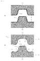
Fig. 2 , the die 10 can be configured so that onebuildup part 13 to fill one lower gap situated between the top part P1 and theprotrusion 101a is formed. - Specifically, since the top part P1 of the product P, after being pressed, forms a convex shape to gradually change in position upward from the connections between the top part P1 and the lateral parts P2 to the middle of the product P in the right-left direction, one
buildup part 13 is formed on the forming surface (the surface corresponding to the top part PI) of the protruding end (uppermost part) of theprotrusion 101a so that the convex shape is a final shape (a shape in which spring back and the like after the press working are not taken into consideration) of the top part P1. In other words, thelower die 101 is modified into the modified lower die 11 by forming, on the forming surface of the protruding end (uppermost part) of theprotrusion 101 a, thebuildup part 13 with the convex shape to gradually change in position in the protruding direction (top direction) of theprotrusion 101a toward the middle, in the right-left direction, of the forming surface of the protruding end (uppermost part) of theprotrusion 101a along the shape of the top part P1 of the product P deformed after being pressed. - Therefore, the top part P1 of the product P can be cooled at a sufficient cooling rate, thus enabling to prevent the hardness of the substantially middle part of the top part P1 in the right-left direction from being smaller than a predetermined value. In this manner, to prevent the hardness of the substantially middle part, whose hardness may particularly be insufficient, of the top part P1 in the right-left direction allows the whole product P to have sufficient hardness.
- With reference to
Figs. 3 and4 , described below is a step S1 for manufacturing thedie 10 as an embodiment of a method for manufacturing a hot-pressing die according to the present invention. - The step S1 is a step for manufacturing the
die 10 out of the die 100 as a conventional hot-pressing die. - As shown in
Fig. 3 , the step S1 includes a first step S11, a second step S12 and athird step S 13, and these steps are performed in mentioned order therein. - The first step S11 is a step for measuring a three-dimensional shape of the forming surface of the die 100 as a conventional hot-pressing die, and a three-dimensional shape of the surface of the product P formed by the
die 100. - In the first step S11, three-dimensional shapes of the forming surfaces of the
lower die 101 and theupper die 102 in thedie 100 are measured. - Then, the three-dimensional shape of the product P which is formed by the
die 100, namely, which is slightly deformed after being pressed by thedie 100 because of spring back and the like, is measured. Specifically, a three-dimensional shape of a surface of the product P facing thelower die 101, and a three-dimensional shape of a surface of the product P facing theupper die 102 are measured. - These measurements may be performed with a contact-type device measuring a shape of an object to be measured by bringing a probe into contact with the object, a noncontact-type device measuring a shape of an object to be measured by irradiating the object with a laser, or the like. The measured three-dimensional shapes, namely, three-dimensional coordinate data are stored in a predetermined storage electrically connected to the device.
- In the present embodiment, the shape of the product P formed by the
die 100 is measured after the shape of the forming surface of thedie 100 is measured, but order of these measurements is not limited thereto. - The second step S12 is a step for calculating, based on the three-dimensional shape of the forming surface of the die 100 as a conventional hot-pressing die, and the three-dimensional shape of the surface of the product P formed by the
die 100 which are measured in the first step S11, three-dimensional shapes of gaps between the forming surface of thedie 100 and the surface of the product P when thedie 100 is closed (when theupper die 102 is at the bottom dead center). - In the second step S12, based on three-dimensional shape of the forming surface of the
lower die 101, and the three-dimensional shape of the surface of the product P facing thelower die 101, three-dimensional shapes (three-dimensional coordinate data) of the lower gaps between these surfaces are calculated. Additionally, based on three-dimensional shape of the forming surface of theupper die 102, and the three-dimensional shape of the surface of the product P facing theupper die 102, three-dimensional shapes (three-dimensional coordinate data) of the upper gaps between these surfaces are calculated. - The calculation of the three-dimensional shapes (three-dimensional coordinate data) of the lower gaps and the upper gaps may be performed with a predetermined arithmetic device electrically connected to the storage in which the three-dimensional shapes (three-dimensional coordinate data), measured in the first step S11, of the forming surfaces of the
lower die 101 and theupper die 102, and the surface of the product P are stored. - The arithmetic device matches any two surfaces as three-dimensional coordinate data to each other at a suitable position (a position at which similarity between the two surfaces is the maximum) to calculate difference between the two surfaces, thereby calculating three-dimensional shapes (three-dimensional coordinate data) of gaps between the two surfaces. An existing arithmetic device may be adopted as the arithmetic device. In the present embodiment, the arithmetic device calculates the three-dimensional shapes (three-dimensional coordinate data) of the lower gaps and the three-dimensional shapes (three-dimensional coordinate data) of the upper gaps based on the three-dimensional shapes (three-dimensional coordinate data), stored in the storage, of the forming surfaces of the
lower die 101 and theupper die 102, and the surface of the product P. - The
third step S 13 is a step for manufacturing thedie 10 by modifying the forming surface of the die 100 based on the three-dimensional shapes, calculated in the second step S12, of the gaps between the forming surface of the die 100 as a conventional hot-pressing die, and the surface of the product P. - In the third step S13, as shown in
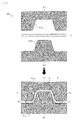
Fig. 4(a) , thebuildup part 13 is formed on the forming surface of thelower die 101 in a predetermined thickness (length from a surface of thebuildup part 13 being in contact with the forming surface of thelower die 101 to an outside surface of the buildup part 13) by performing overlay welding of the whole forming surface of thelower die 101, and thebuildup part 14 is formed on the forming surface of theupper die 102 in a predetermined thickness (length from a surface of thebuildup part 14 being in contact with the forming surface of theupper die 102 to an outside surface of the buildup part 14) by performing overlay welding of the whole forming surface of theupper die 102. - Then, as shown in
Fig. 4(b) , the plurality ofbuildup parts 13 coinciding in form with the lower gaps are formed by cutting thebuildup part 13 formed on the forming surface of thelower die 101 based on the three-dimensional shapes of the lower gaps calculated in the second step S12, and the plurality ofbuildup parts 14 coinciding in form with the upper gaps are formed by cutting thebuildup part 14 formed on the forming surface of theupper die 102 based on the three-dimensional shapes of the upper gaps calculated in the second step S12. Specifically, the plurality ofbuildup parts 13 coinciding in form with the lower gaps are formed by performing numerical control machining of thebuildup part 13 formed on the forming surface of thelower die 101 after applying the three-dimensional coordinate data of the lower gaps to data for the numerical control machining, and the plurality ofbuildup parts 14 coinciding in form with the upper gaps are formed by performing numerical control machining of thebuildup part 14 formed on the forming surface of theupper die 102 after applying the three-dimensional coordinate data of the upper gaps to data for the numerical control machining. - Thus, the modified lower die 11 and the modified
upper die 12 are fabricated, the modified lower die 11 having thelower die 101 and the plurality ofbuildup parts 13 formed on the forming surface of thelower die 101 so as to fill the lower gaps, the modified upper die 12 having theupper die 102 and the plurality ofbuildup parts 14 formed on the forming surface of theupper die 102 so as to fill the upper gaps. - As mentioned above, in the step S1, passing through the first step S11, the second step S12 and the third step S13 in order, the die 10 having the modified lower die 11 and the modified
upper die 12 is manufactured. - In the step S1, the three-dimensional shape of the forming surface of the die 100 as a conventional hot-pressing die, and the three-dimensional shape of the surface of the product P formed by the
die 100 are measured, and then thedie 10 is manufactured so that the product P deformed slightly after being pressed by thedie 100 because of spring back and the like coincides in form with the space between the forming surfaces of the modified lower die 11 and the modified upper die 12 positioned at the bottom dead center. - In other words, the
die 10 is manufactured in consideration of the deformation of the product P after being pressed by thedie 100 as a conventional hot-pressing die. - Therefore, even the product P pressed by the
die 10 deforms because of spring back and the like, but, compared with the product P pressed by thedie 100 as a conventional hot-pressing die, an influence of spring back and the like occurring in the product P is controlled to a minimum, and deformation amount of the product P is reduced. - Consequently, during the quenching, a contact area between the product P and the die 10 can be increased, and the product P can suitably be cooled.
- In the present embodiment, the
die 10 is manufactured by forming the plurality ofbuildup parts 13 and the plurality ofbuildup parts 14 on the forming surface of thelower die 101 and the forming surface of theupper die 102 respectively, namely, by performing overlay welding of the forming surface of the die 100 as a conventional hot-pressing die. However, thedie 10 may be manufactured by cutting the forming surface of thedie 100, or by performing overlay welding and cutting of the forming surface of thedie 100. - Moreover, the
die 10 may be manufactured out of a predetermined ingot. - With reference to
Fig. 5 , described below is a die 20 as another embodiment of a hot-pressing die. - The
die 20 is a hot-pressing die. Thedie 20 is fixed to a predetermined pressing machine (not shown), and performs the hot-press forming of the workpiece W to produce the product P. - For convenience, a top-bottom direction in
Fig. 5 is defined as a top-bottom direction of the die 20, and a right-left direction inFig. 5 is defined as a right-left direction of thedie 20. In addition, this side inFig. 5 is defined as a front side of the die 20, and the far side inFig. 5 is defined as a rear side of the die 20, thereby a front-rear direction of the die 20 being defined. - As shown in
Fig. 5 , thedie 20 includes a modified lower die 21 and theupper die 102 which are arranged so that the forming surfaces thereof are opposed to each other. - The modified lower die 21 has a working
part 22, a pair ofbackup parts 23, and a pair ofshims 24. - The working
part 22 corresponds to theupper die 102, and is substantially similar in configuration to the lower die 101 (seeFig. 7 ) of the die 100 as a conventional hot-pressing die. The workingpart 22 has aprotrusion 22a which protrudes upward along the shape of therecess 102a of theupper die 102 from the intermediate part (the substantially middle part), in the right-left direction, of the forming surface (the upper surface) thereof. - The
protrusion 22a forms, with therecess 102a of theupper die 102, the top part P1 and the lateral parts P2 of the product P. Theprotrusion 22a is substantially similar in configuration to theprotrusion 101a of thelower die 101. The surface of theprotrusion 22a corresponding to the top part P1 substantially horizontally extends in the right-left direction, and the two surfaces of theprotrusion 22a corresponding to the lateral parts P2 are inclined to gradually separate from each other toward the bottom ends thereof. - The
backup parts 23 are configured to sandwich theupper die 102 positioned at the bottom dead center therebetween in the right-left direction. Thebackup parts 23 control deformation (flexure) of theupper die 102 to a minimum when the workpiece W is pressed. - Specifically, the
backup parts 23 are formed integrally with the workingpart 22 at respective ends of the workingpart 22 in the right-left direction, and protrude upward above the forming surface of the modified lower die 21. The inner surfaces (the surfaces facing theupper die 102 positioned at the bottom dead center) of thebackup parts 23 correspond to the outer surfaces of theupper die 102 in the right-left direction, and come in contact with the outer surfaces of theupper die 102 in the right-left direction. - The
backup parts 23 configured as mentioned above control deformation of theupper die 102 to a minimum by applying a force in opposite direction of the deformation to theupper die 102 which deforms so that the parts of theupper die 102 other than therecess 102a move away from each other when the workpiece W is pressed. The deformation of theupper die 102 is controlled to a minimum, thus enabling to suitably press the workpiece W, and to control a reduction of a contact area between the product P and the die 20 to a minimum during the quenching. - The
shims 24 are plates each having a predetermined thickness (dimension in the right-left direction). Theshims 24 are fixed to the inner surfaces (the surfaces facing the upper die 102) of thebackup parts 23 so as to intervene between thebackup parts 23 and theupper die 102 when the workpiece W is pressed. - During the press working of the workpiece W, since deformation of the
upper die 102 cause thebackup parts 23 to deform to slightly move away from each other, it is difficult for thebackup parts 23 to completely prevent theupper die 102 from deforming. - However, if the
shims 24 are fixed to the inner surfaces (the surfaces facing the upper die 102) of thebackup parts 23 so as to intervene between the inner surfaces of thebackup parts 23 and the outer surfaces of theupper die 102 in the right-left direction when the workpiece W is pressed, the length between thebackup parts 23 is reduced by the thicknesses of theshims 24, and an increased force is applied, in opposite direction of the deformation, to theupper die 102 which deforms so that the parts of theupper die 102 other than therecess 102a move away from each other. - This makes it possible to further restrain the parts of the
upper die 102 other than therecess 102a from moving away from each other, and to suitably press the workpiece W. - Therefore, a contact area between the product P and the die 20 can be increased without increasing a pressure at which the workpiece W is pressed, and the product P can suitably be cooled during the quenching.
- Note that there is no space between the inner surfaces (the surfaces facing the upper die 102) of the
backup parts 23 and the outer surfaces, in the right-left direction, of theupper die 102 positioned at the bottom dead center, but shims each having an extremely small thickness (dimension in the right-left direction) can be inserted between them since thebackup parts 23 and theupper die 102 slightly deform as mentioned previously. - With reference to
Fig. 6 , described below is a die 30 as another embodiment of a hot-pressing die. - The
die 30 is a hot-pressing die. Thedie 30 is fixed to a predetermined pressing machine (not shown), and performs the hot-press forming of the workpiece W to produce the product P. - For convenience, a top-bottom direction in
Fig. 6 is defined as a top-bottom direction of the die 30, and a right-left direction inFig. 6 is defined as a right-left direction of thedie 30. In addition, this side inFig. 6 is defined as a front side of the die 30, and the far side inFig. 6 is defined as a rear side of the die 30, thereby a front-rear direction of the die 30 being defined. - As shown in
Fig. 6 , thedie 30 includes thelower die 101 and a modified upper die 32 which are arranged so that the forming surfaces thereof are opposed to each other. - The modified
upper die 32 is substantially similar in configuration to the upper die 102 (seeFig. 7 ) of the die 100 as a conventional hot-pressing die, and has a plurality ofslits 33 formed on the forming surface (the lower surface) of the modifiedupper die 32. In other words, the modifiedupper die 32 differs from theupper die 102 in having the plurality ofslits 33. Moreover, the modifiedupper die 32 has arecess 32a in which the intermediate part (the substantially middle part), in the right-left direction, of the forming surface thereof dents upward along the shape of theprotrusion 101 a of thelower die 101. - The
recess 32a forms, with theprotrusion 101a of thelower die 101, the top part P1 and the lateral parts P2 of the product P. The surface of therecess 32a corresponding to the top part P1 substantially horizontally extends in the right-left direction, and the two surfaces of therecess 32a corresponding to the lateral parts P2 are inclined to gradually separate from each other toward the bottom ends thereof. - The
slit 33 is formed inward from the forming surface of therecess 32a of the modifiedupper die 32, and is continuously formed throughout the area of therecess 32a in the front-rear direction. Theslit 33 is formed substantially perpendicularly to a part of the forming surface on which theslit 33 is formed. The plurality ofslits 33 are formed on the forming surface of therecess 32a, and are arranged at predetermined intervals. - As mentioned above, the plurality of
slits 33 are formed to divide the forming surface of therecess 32a into a plurality of parts in the front-rear direction. - This makes it possible to bend the modified
upper die 32, further than theupper die 102, so that the parts of the modified upper die 32 other than therecess 32a move away from each other when the workpiece W is pressed, and to transform the forming surface of the modified upper die 32 along the shape of the product P to efficiently bring the forming surface of the modified upper die 32 into contact with the surface of the product P. - Therefore, a contact area between the product P and the die 30 can be increased without increasing a pressure at which the workpiece W is pressed, and the product P can suitably be cooled during the quenching.
- In the present embodiment, the plurality of
slits 33 are formed only on the forming surface of therecess 32a. However, in addition to this, the plurality ofslits 33 may be formed on the outer surfaces of theupper die 102 in the right-left direction. - In each embodiment as mentioned above, a protrusion (e.g. the
protrusion 101a) is formed in a lower die (e.g. the lower die 101), and a recess (e.g. therecess 102a) is formed in an upper die (e.g. the upper die 102). However, the recess may be formed in the lower die, and the protrusion may be formed in the upper die. - The present invention is applied to a hot-pressing die which presses and cools a heated workpiece at the same time, and to a method for manufacturing the hot-pressing die.
-
- 10: die
- 11: modified lower die
- 12: modified upper die
- 13: buildup part
- 14: buildup part
- 20: die
- 21: modified lower die
- 22: working part
- 23: backup part
- 24: shim
- 30: die
- 32: modified upper die
- 33: slit
- 100: die
- 101: lower die
- 101 a: protrusion
- 102: upper die
- 102a: recess
- W: workpiece
- P: product
Claims (2)
- A hot-pressing die which presses and cools a heated workpiece at the same time to form a product having a shape in which a hat-shaped section continues in a front-rear direction, comprising:a lower die having a lower forming surface; andan upper die having an upper forming surface facing the lower forming surface,wherein one of the lower die and the upper die has a protrusion formed on the forming surface of said one to protrude toward the other, the protrusion being formed in an intermediate part, in a right-left direction perpendicular to the front-rear direction, of the forming surface of said one,the other of the lower die and the upper die has a recess formed on the forming surface of the other, the recess corresponding to the protrusion,the protrusion has a section formed at a protruding end thereof, the section being modified to form a convex to gradually change in position in a protruding direction of the protrusion toward the middle of the section in the right-left direction.
- A method for manufacturing a hot-pressing die which presses and cools a heated workpiece at the same time to form a product, comprising:a first step for measuring a three-dimensional shape of a forming surface of the hot-pressing die, and a three-dimensional shape of a surface of the product formed by the hot-pressing die;a second step for calculating, based on the three-dimensional shape of the hot-pressing die and the three-dimensional shape of the surface of the product measured in the first step, a three-dimensional shape of a gap between the forming surface of the hot-pressing die and the surface of the product when the hot-pressing die is closed after the press working; anda third step for modifying, based on the three-dimensional shape of the gap calculated in the second step, the forming surface of the hot-pressing die so as to fill the gap.
Applications Claiming Priority (1)
| Application Number | Priority Date | Filing Date | Title |
|---|---|---|---|
| PCT/JP2011/061189 WO2012157064A1 (en) | 2011-05-16 | 2011-05-16 | Metal mold for hot pressing and method for manufacturing metal mold for hot pressing |
Publications (2)
| Publication Number | Publication Date |
|---|---|
| EP2711101A1 true EP2711101A1 (en) | 2014-03-26 |
| EP2711101A4 EP2711101A4 (en) | 2014-11-12 |
Family
ID=47176433
Family Applications (1)
| Application Number | Title | Priority Date | Filing Date |
|---|---|---|---|
| EP11865642.0A Withdrawn EP2711101A4 (en) | 2011-05-16 | 2011-05-16 | HOT PRESSURE METALLIC MOLD AND METHOD FOR MANUFACTURING HOT PRESSURE METALLIC MOLD |
Country Status (5)
| Country | Link |
|---|---|
| US (1) | US9452460B2 (en) |
| EP (1) | EP2711101A4 (en) |
| JP (1) | JP5644942B2 (en) |
| CN (1) | CN103561880B (en) |
| WO (1) | WO2012157064A1 (en) |
Cited By (2)
| Publication number | Priority date | Publication date | Assignee | Title |
|---|---|---|---|---|
| US12280415B2 (en) | 2019-04-29 | 2025-04-22 | Autotech Engineering S.L. | Cold working apparatus and a method for cold working a blank |
| US12280413B2 (en) | 2019-04-29 | 2025-04-22 | Autotech Engineering S.L. | Hot press forming apparatus and a method for hot press forming a blank |
Families Citing this family (9)
| Publication number | Priority date | Publication date | Assignee | Title |
|---|---|---|---|---|
| US9828128B1 (en) | 2014-12-17 | 2017-11-28 | X Development Llc | On-demand protective structures for packaging items in a container |
| US9840347B1 (en) | 2014-12-17 | 2017-12-12 | X Development LLX | Adhering modular elements for packaging structures |
| CN104551346A (en) * | 2015-01-13 | 2015-04-29 | 哈尔滨电机厂有限责任公司 | Method for improving wear resistance of thick-plate bending and forming mould by means of surfacing |
| CN107435094B (en) * | 2016-05-27 | 2019-10-01 | 燕山大学 | A process method for improving hardness of pure iron parts |
| CN109967619B (en) * | 2017-12-28 | 2020-10-13 | 航天海鹰(哈尔滨)钛业有限公司 | A one-step hot pressing forming die for titanium alloy skin with large curvature and variable section |
| CN109182688B (en) * | 2018-11-13 | 2025-05-16 | 成都天马铁路轴承有限公司 | Bearing outer ring compression quenching die |
| EP3736057A1 (en) * | 2019-05-08 | 2020-11-11 | Koninklijke Philips N.V. | Method of forming teeth of a cutting blade or guard |
| CN111804786B (en) * | 2020-05-22 | 2022-07-05 | 北京卫星制造厂有限公司 | Integral wall plate step-by-step progressive thermoforming and thermal sizing integrated method |
| JP7659713B1 (en) * | 2024-11-18 | 2025-04-09 | 株式会社ジーテクト | Mold, mold manufacturing method, and mold inspection method |
Family Cites Families (17)
| Publication number | Priority date | Publication date | Assignee | Title |
|---|---|---|---|---|
| JP2002241835A (en) * | 2001-02-20 | 2002-08-28 | Aisin Takaoka Ltd | Method for partially strengthening work |
| JP4019412B2 (en) | 2002-02-19 | 2007-12-12 | マツダ株式会社 | NC machining data creation method, creation device, creation program and recording medium thereof for mold machining |
| JP3863874B2 (en) * | 2003-10-02 | 2006-12-27 | 新日本製鐵株式会社 | Hot press forming apparatus and hot press forming method for metal plate material |
| CN2762913Y (en) * | 2005-01-17 | 2006-03-08 | 李富祥 | High pressure formation dies |
| JP2006326620A (en) | 2005-05-25 | 2006-12-07 | Toa Kogyo Kk | Press forming device, and press forming method |
| DE102005042765C5 (en) * | 2005-09-08 | 2013-01-03 | Voestalpine Automotive Gmbh | mold |
| JP4890416B2 (en) * | 2007-10-18 | 2012-03-07 | アイシン高丘株式会社 | Press working apparatus and press working method in die quench method |
| JP5056643B2 (en) * | 2008-07-18 | 2012-10-24 | 住友金属工業株式会社 | Bumper reinforcement and manufacturing method thereof |
| JP5199805B2 (en) * | 2008-09-24 | 2013-05-15 | 東プレ株式会社 | Die quench processed product, manufacturing method and manufacturing apparatus thereof |
| CN201316764Y (en) | 2008-12-04 | 2009-09-30 | 江苏华阳金属管件有限公司 | Pipe cap forming mould |
| EP2367962B2 (en) * | 2008-12-19 | 2018-07-18 | voestalpine Metal Forming GmbH | Method for producing partially hardened components from sheet steel |
| JP5445204B2 (en) * | 2009-02-16 | 2014-03-19 | 新日鐵住金株式会社 | Boundary condition setting method for hot press forming simulation |
| JP5783249B2 (en) * | 2011-05-26 | 2015-09-24 | トヨタ自動車株式会社 | Hot press equipment |
| JP5759281B2 (en) * | 2011-06-20 | 2015-08-05 | 理想科学工業株式会社 | Image processing device |
| WO2013005318A1 (en) * | 2011-07-06 | 2013-01-10 | トヨタ自動車株式会社 | Hot press forming method, and hot press device |
| US20140190233A1 (en) * | 2011-08-29 | 2014-07-10 | Toyota Jidosha Kabushiki Kaisha | Metal mold for hot pressing |
| JP6093630B2 (en) * | 2013-04-12 | 2017-03-08 | 東プレ株式会社 | Manufacturing method of hot press products |
-
2011
- 2011-05-16 CN CN201180070846.7A patent/CN103561880B/en not_active Expired - Fee Related
- 2011-05-16 EP EP11865642.0A patent/EP2711101A4/en not_active Withdrawn
- 2011-05-16 WO PCT/JP2011/061189 patent/WO2012157064A1/en not_active Ceased
- 2011-05-16 US US14/117,776 patent/US9452460B2/en not_active Expired - Fee Related
- 2011-05-16 JP JP2013514903A patent/JP5644942B2/en not_active Expired - Fee Related
Cited By (2)
| Publication number | Priority date | Publication date | Assignee | Title |
|---|---|---|---|---|
| US12280415B2 (en) | 2019-04-29 | 2025-04-22 | Autotech Engineering S.L. | Cold working apparatus and a method for cold working a blank |
| US12280413B2 (en) | 2019-04-29 | 2025-04-22 | Autotech Engineering S.L. | Hot press forming apparatus and a method for hot press forming a blank |
Also Published As
| Publication number | Publication date |
|---|---|
| US20140069163A1 (en) | 2014-03-13 |
| EP2711101A4 (en) | 2014-11-12 |
| WO2012157064A1 (en) | 2012-11-22 |
| CN103561880A (en) | 2014-02-05 |
| CN103561880B (en) | 2015-08-05 |
| JP5644942B2 (en) | 2014-12-24 |
| US9452460B2 (en) | 2016-09-27 |
| JPWO2012157064A1 (en) | 2014-07-31 |
Similar Documents
| Publication | Publication Date | Title |
|---|---|---|
| EP2711101A1 (en) | Metal mold for hot pressing and method for manufacturing metal mold for hot pressing | |
| US20140130564A1 (en) | Hot-pressing apparatus | |
| US20100018277A1 (en) | Apparatus for hot-forming, press-quenching, and cutting semifinished hardenable-steel workpiece | |
| KR101874277B1 (en) | Method of manufacturing press-formed article, press-molded article, mold and press apparatus | |
| JP6512191B2 (en) | Method of designing mold and method of manufacturing press-formed product | |
| JP6249132B2 (en) | Press molded product production line | |
| KR101718470B1 (en) | Method of analyzing press forming | |
| EP2953742B1 (en) | Hot die forming assembly and method of making a heat treated part | |
| CN106794507A (en) | Method for press forming | |
| JP2018020350A (en) | Manufacturing method of press-molded products | |
| JP6156608B1 (en) | Manufacturing method of stretch flange molded parts | |
| KR20180105216A (en) | Manufacturing method of press molded article | |
| JP6717269B2 (en) | Press forming method for automobile outer panel | |
| JP6387866B2 (en) | Press mold | |
| RU2701435C1 (en) | Method of making a metal element | |
| KR20110065068A (en) | Cooling channel design method of hot stamping mold | |
| JP6350498B2 (en) | Press wrinkle generation judgment method | |
| JP6176430B1 (en) | Manufacturing method of press-molded products | |
| JP2017042825A (en) | Manufacturing method for molded component with stretch flange | |
| JP6493331B2 (en) | Manufacturing method of press-molded products | |
| JP6319383B2 (en) | Manufacturing method of stretch flange molded parts | |
| JP6330766B2 (en) | Press forming method | |
| EP2845662B1 (en) | Press and method for the manufacture of a profile | |
| JP2022065857A (en) | How to determine molding mold, molding method and molding conditions | |
| JP6044571B2 (en) | DAMAGE DAMAGE DAMAGE PREDICTION METHOD FOR CUT DIE AND CUT DIE DAMAGE PREVENTION METHOD USING THE PREDICTION METHOD |
Legal Events
| Date | Code | Title | Description |
|---|---|---|---|
| PUAI | Public reference made under article 153(3) epc to a published international application that has entered the european phase |
Free format text: ORIGINAL CODE: 0009012 |
|
| 17P | Request for examination filed |
Effective date: 20131212 |
|
| AK | Designated contracting states |
Kind code of ref document: A1 Designated state(s): AL AT BE BG CH CY CZ DE DK EE ES FI FR GB GR HR HU IE IS IT LI LT LU LV MC MK MT NL NO PL PT RO RS SE SI SK SM TR |
|
| RAP1 | Party data changed (applicant data changed or rights of an application transferred) |
Owner name: TOYOTA JIDOSHA KABUSHIKI KAISHA |
|
| RIN1 | Information on inventor provided before grant (corrected) |
Inventor name: ISHII, SHINJI Inventor name: NOJIRI, ISAO |
|
| RIN1 | Information on inventor provided before grant (corrected) |
Inventor name: NOJIRI, ISAO Inventor name: ISHII, SHINJI |
|
| DAX | Request for extension of the european patent (deleted) | ||
| A4 | Supplementary search report drawn up and despatched |
Effective date: 20141015 |
|
| RIC1 | Information provided on ipc code assigned before grant |
Ipc: B21D 5/01 20060101AFI20141009BHEP Ipc: B21D 22/20 20060101ALI20141009BHEP |
|
| RIC1 | Information provided on ipc code assigned before grant |
Ipc: B21D 5/01 20060101AFI20141107BHEP Ipc: B21D 22/20 20060101ALI20141107BHEP |
|
| STAA | Information on the status of an ep patent application or granted ep patent |
Free format text: STATUS: EXAMINATION IS IN PROGRESS |
|
| 17Q | First examination report despatched |
Effective date: 20170522 |
|
| GRAP | Despatch of communication of intention to grant a patent |
Free format text: ORIGINAL CODE: EPIDOSNIGR1 |
|
| STAA | Information on the status of an ep patent application or granted ep patent |
Free format text: STATUS: GRANT OF PATENT IS INTENDED |
|
| INTG | Intention to grant announced |
Effective date: 20190730 |
|
| STAA | Information on the status of an ep patent application or granted ep patent |
Free format text: STATUS: THE APPLICATION IS DEEMED TO BE WITHDRAWN |
|
| 18D | Application deemed to be withdrawn |
Effective date: 20191210 |