EP2710915A2 - Zip fastener and luggage - Google Patents
Zip fastener and luggage Download PDFInfo
- Publication number
- EP2710915A2 EP2710915A2 EP13004366.4A EP13004366A EP2710915A2 EP 2710915 A2 EP2710915 A2 EP 2710915A2 EP 13004366 A EP13004366 A EP 13004366A EP 2710915 A2 EP2710915 A2 EP 2710915A2
- Authority
- EP
- European Patent Office
- Prior art keywords
- zip fastener
- sliders
- pull tabs
- pull
- luggage
- Prior art date
- Legal status (The legal status is an assumption and is not a legal conclusion. Google has not performed a legal analysis and makes no representation as to the accuracy of the status listed.)
- Granted
Links
Images






Classifications
-
- A—HUMAN NECESSITIES
- A44—HABERDASHERY; JEWELLERY
- A44B—BUTTONS, PINS, BUCKLES, SLIDE FASTENERS, OR THE LIKE
- A44B19/00—Slide fasteners
- A44B19/02—Slide fasteners with a series of separate interlocking members secured to each stringer tape
- A44B19/04—Stringers arranged edge-to-edge when fastened, e.g. abutting stringers
- A44B19/06—Stringers arranged edge-to-edge when fastened, e.g. abutting stringers with substantially rectangular members having interlocking projections and pieces
-
- A—HUMAN NECESSITIES
- A44—HABERDASHERY; JEWELLERY
- A44B—BUTTONS, PINS, BUCKLES, SLIDE FASTENERS, OR THE LIKE
- A44B19/00—Slide fasteners
- A44B19/24—Details
- A44B19/26—Sliders
- A44B19/262—Pull members; Ornamental attachments for sliders
-
- A—HUMAN NECESSITIES
- A44—HABERDASHERY; JEWELLERY
- A44B—BUTTONS, PINS, BUCKLES, SLIDE FASTENERS, OR THE LIKE
- A44B19/00—Slide fasteners
- A44B19/24—Details
- A44B19/26—Sliders
- A44B19/30—Sliders with means for locking in position
- A44B19/301—Sliders with means for locking in position at the end of their upward travel with any suitable device, e.g. pull member combined with a press-button, a hook, a key-operated lock
-
- A—HUMAN NECESSITIES
- A45—HAND OR TRAVELLING ARTICLES
- A45C—PURSES; LUGGAGE; HAND CARRIED BAGS
- A45C13/00—Details; Accessories
- A45C13/10—Arrangement of fasteners
- A45C13/1023—Arrangement of fasteners with elongated profiles fastened by sliders
- A45C13/103—Arrangement of zip-fasteners
-
- Y—GENERAL TAGGING OF NEW TECHNOLOGICAL DEVELOPMENTS; GENERAL TAGGING OF CROSS-SECTIONAL TECHNOLOGIES SPANNING OVER SEVERAL SECTIONS OF THE IPC; TECHNICAL SUBJECTS COVERED BY FORMER USPC CROSS-REFERENCE ART COLLECTIONS [XRACs] AND DIGESTS
- Y10—TECHNICAL SUBJECTS COVERED BY FORMER USPC
- Y10T—TECHNICAL SUBJECTS COVERED BY FORMER US CLASSIFICATION
- Y10T24/00—Buckles, buttons, clasps, etc.
- Y10T24/25—Zipper or required component thereof
- Y10T24/2509—Plural independently movable sliders
Definitions
- the present invention relates to zip fasteners with security features, and more particularly, to such zip fasteners having two moveable sliders that each mesh and unmesh the teeth of the fastener, allowing it be opened at any point along its length.
- the invention also relates to luggage, on which such zip fasteners may be provided.
- Zip fasteners with two sliders are often used in various applications where a degree of security is desirable. Locking or securing the zip fastener can be achieved by locking each of the sliders to a stationary fixture, or else by locking the two sliders together.
- Each zip slider may be connected to a proximal end of a pull tab, with an aperture being formed in the opposing distal end of the pull tab. This arrangement allows for a securing device, such as the shackle of a padlock or a cable tie, to be fixed through both of the apertures in the distal ends of the pull tabs, to thereby lock the two sliders together and secure the closure.
- two sliders connected in this manner can still readily be moved together along the stringers as desired, by grasping one or both of the connected pull tabs in the conventional way.
- a key or combination locking system which has a sliding pin that can be extended through the aperture in the distal end of a pull tab, for securing the slider to the luggage item in place.
- a drawback of this alignment is that, intuitively, a thief would tend to pull the pull tabs apart in the longitudinal direction to separate the sliders and open the zip fastener, so this arrangement would not defeat even the most quick or casual attentions of a thief.
- a zip fastener comprising:
- first and second pull tabs each have a body elongated between opposing proximal and distal ends, openings are provided in each distal end, and the openings in the distal ends are in registration with one another in the interlocked position.
- the first and second pull tabs each have a body elongated between opposing proximal and distal ends, at least one of the first and second pull tabs includes a hook disposed between its proximal and distal ends, a tip of the hook being spaced from the body, such that the female locking feature comprises a recess between the body and the tip of the hook, and the male locking feature comprises at least a complementary part of the body of the other of the first and second pull tabs, which complementary portion may be received in the recess.
- opposing inner surfaces of the recess are substantially planar, and opposing outer surfaces of the complementary portion of the body received in the female locking feature are substantially planar.
- first and second pull tabs are of like form.
- each pull tab has a respective outermost surface disposed outermost when the first and second pull tabs are in their interlocked position, and a concavity in each outermost surface that bounds the complementary portion of the body received in the recess, such that in the interlocked position, said outermost surfaces are substantially aligned coplanar with a respective outer surface of the tip of the hook.
- openings are formed at the proximal ends, the first and second sliders each including a loop extending substantially in the lengthwise direction through the openings at the proximal ends, the loop on the first slider and the opening in the proximal end of the first pull tab forming the first coupling, and the loop on the second slider and the opening in the proximal end of the second pull tab forming a second coupling.
- the tip of the hook is sized or formed such that it cannot mistakenly be inserted into the recess and the openings in the distal ends aligned.
- the hook is integral with the body, and includes a flange portion connecting the tip to the body, the flange portion extending from an edge of the body.
- a detent for holding the male and female locking features in mutual engagement.
- the detent may comprise a magnet received in an aperture in the male locking feature, or a snap connection.
- luggage comprising at least one zip fastener as described above, and further including a fastening device for connecting the first and second pull tabs.
- the fastening device may include: a body fixed to the luggage, the body having at least one pin portion having a projecting free end and an opposing fixed end, the pin portion being configured to be received in the openings in the distal ends, and a closure engaged with the body for sliding movement between a closed position in which the closure blocks the free end and an open position in which the closure is spaced apart from the free end.
- the body further comprises an opening positioned such that with the closure in the closed position a shackle of a padlock extending through the aperture secures the closure.
- the at least one zip fastener comprises two zip fasteners, and the fastening device is fixed to the luggage between the two zip fasteners.
- This invention thus provides a zip fastener device and bag with improved security, without the complexity and consequent high manufacturing costs of many of the prior art solutions.
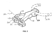
- a first embodiment of a zip fastener 20 generally comprises a first slider 10, and a second slider 11 both engaged with a pair of stringers 12, 13 which may be connected together by means of meshed teeth 14, in the well known manner. Additionally, two pull tabs 15, 16 are provided, one may be connected to each of the sliders, to allow for improved purchase for the user to pull the sliders 10, 11 along the stringers 12, 13. Relative movement between the sliders 10, 11 along the stringers 12, 13 opens and closes the zip fastener or, more specifically, opens and closes an opening 17 between the stringers 12, 13 and sliders 10, 11.
- a first coupling 200a connects the proximal end of the first pull tab 15 to the first slider 10, and second coupling 200b connects the second pull tab 16 to the second slider 11.
- the couplings 200a, 200b allow the pull tabs 15, 16 to rotate about a pivot axis 32 extending substantially in the lengthwise direction of the stringers 12, 13.
- the proximal ends of the pull tabs 15, 16 may be fixed to the sliders 10, 11 loop 30 fixed to a top plate 31, the loops 30 extending generally in the lengthwise direction of the stringers.
- the loops 30 and proximal end openings 24 in the pull tabs 15, 16 in which the loops 30 are received provide the two parts of the couplings 200a, 200b which, in addition to other movements, allows relative rotation between the sliders 10, 11 and the pull tabs 15, 16 about pivot axis 32.
- the pull tabs 15, 16 each have a body 28 generally elongated in the direction of long axis 201 between opposing proximal and distal ends, with openings 23 provided in each distal end.
- the pull tabs 15, 16 have complementary male and female locking features, exemplified in the first embodiment by a female locking feature in the form of recess 22 formed by a hook 21 on the first pull tab 15.
- the recess 22 receives a male complementary part 29 on the body of the second pull tab 16.
- the engagement between the male and female locking features hinders separation of the sliders 10, 11 required to move them to their open position and the tabs 15, 16 are restrained to rotate together about the longitudinal axis 32, but are no longer able to rotate about a transverse axis.
- the pull tabs 15, 16 are also prevented from relative rotation about the fastening device 25, or the common axis of openings 23, owing to the engagement between the sliders 10, 11 and the stringers 12, 13.
- the first and second pull tabs 15, 16 are of like form, thus reducing the number of different parts making up the zip fastener.
- the proximal end opening 24 in the proximal end and the distal end opening 23 in the opposing distal end both extend generally transversely through the elongate body 28.
- the hook 21 is located between the proximal and distal ends, and may project to one side of the main body 28, with which it may be integral.
- the hook 21 may include a flange portion 26 projecting transversely from the main body 28, and a tip 27 laterally spaced from the elongate body 28 to define the recess 22.
- the tip 27 of the hook 21 may have a convex or rounded form.
- the flange portion 26 may be tapered in the longitudinal direction between the main body 28 and the tip 27.
- the tip 27 and the female locking feature or recess 22 are preferably elongate, and may be elongated in a direction generally aligned with the longitudinal axis 201 of the pull tabs.
- the main body 28 may have a longitudinally stepped form, with a central section 29 offset transversely to a first side from the adjacent proximal ends, the hook 21 being offset to the first side of the central section 29.
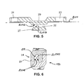
- opposing inner surfaces 202, 203 of the recess 22 are substantially planar, and opposing outer surfaces 204, 205 of the complementary portion 29 of the body that received in the recess 22 are substantially planar, and extend in the direction of long axis 201, or at an acute angle to the longitudinal axes 201.
- Figs 7a-7c illustrate a second embodiment which is generally like the first embodiment except the shape of the tip 21, which has a rectangular form with its long side generally aligned in the direction of the long axis 201.
- a detent for holding the male and female locking features in mutual engagement in the interlocked position comprises a permanent magnet 207 received in an aperture in the male locking feature or body portion 29 of each of the pull tabs 115, 116.
- Each pull tabs 115, 116 has a respective outermost surface 208 disposed outermost when the first and second pull tabs are in their interlocked position, and a concavity 209 in each outermost surface 208.
- the concavity 209 bounds the complementary portion 29 of the body received in the recess 22, such that in the interlocked position, the outermost surface 208 is substantially aligned coplanar with a respective outer surface 210 of the tip 21 of the hook.
- both pull tabs 115, 116 are identical and are disposed on the zip fastener facing in opposite directions (180° apart about the longitudinal axis 201) such that their respective tips 21 face one another.
- the tips 21 of the hooks 21 are aligned transversely with reference to their respective longitudinal axes 201, such that the recesses 22 open transversely.
- Figs 8a-8c illustrate a third embodiment which is generally like the first embodiment except the shape of the tip 21, which has a generally semi-circular edge 211.
- a detent for holding the male and female locking features in mutual engagement in the interlocked position comprises a permanent magnet 207 received in an aperture in the male locking feature or body portion 29 of each of the pull tabs 215, 216.
- Each pull tabs 215, 216 has a respective outermost surface 208 disposed outermost when the first and second pull tabs are in their interlocked position, and a concavity 209 in each outermost surface 208.
- the concavity 209 bounds the complementary portion 29 of the body received in the recess 22, such that in the interlocked position, the outermost surface 208 is substantially aligned coplanar with a respective outer surface 210 of the tip 21 of the hook.
- a fourth embodiment of a zip fastener is shown in Figs. 9 and 10 and generally comprises a first pull tab 315 in which a female locking feature in the form of a concavity 121b is formed in the body intermediate between its proximal and distal ends, adjacent a male locking feature in the form of body portion 122b.
- the second pull tab 316 has a female locking feature in the form of a concavity 121a adjacent a male locking feature in the form of body portion 122a.
- the pull tabs 315, 316 are interlocked in like slide-and-turn manner to the first embodiment, firstly sliding the sliders 10, 11 together to the closed position, before rotating one of the pull tabs 315, 316 relative to the other about the pivot axis 32 to mutually engages the male and female locking features, whereupon the second pull tab 316 crosses over from one side to the other of the pull tab 315 and body portion 122a is received in the concavity 121b, and the body portion 122b is received in the concavity 121a, to interlock the first and second pull tabs in an interlocked position that prevents movement of the sliders 10, 11 to their open position.
- the pull tabs 315, 316 are different (i.e. right and left-handed).
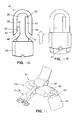
- Figs 11-14 illustrate an alternative fastening device 125 for connecting the pull tabs, to a piece of luggage, such as a backpack 35 including the zip fastener 20 and with which fastening device 125 may be employed.
- the backpack 35 includes a security strap 36 which may be reinforced with metal threads, one longitudinal end of which is fixed to the backpack, as to the shoulder strap 37, and the opposing free end of which may be provided with a loop 38. If it is necessary to leave the backpack 35 the security strap 36 is used to secure it against opportunistic theft by locking around a fixed item such as a post, or a more massive item such as a piece of furniture.
- the fastening device 125 secures both this strap 36 and the pull tabs 15, 115, 215, 315, 16, 116, 216, 316.
- the fastening device 125 may comprise a body 41 formed of a U-shaped bar section 39 to the inside of which is fixed a web 40.
- Two elongate slots 42, 43 may be provided in the web 40, each slot extending from a respective mouth 46, 47 to a closed end 44, 45, each slot 42, 43 extending adjacent a respective pin portion 48, 49 having a projecting end adjacent the respective mouth 46, 47.
- a closure 50 may be in the form of a sleeve in which the body 41 is slidingly received for movement between a closed position ( Fig. 11 ) in which the closure 50 closes the mouths 46, 47 and an extended position ( Fig. 12 ) in which the closure 50 opens the mouths 46, 47.
- the distal ends of the interlocked pull tabs can be entered through the mouth 46 before pin portion 48 is inserted into the distal end openings 23.
- the loop 38, or an end fitting on the strap 36 may likewise be entered through the mouth 47 before pin portion 49 is inserted into the loop or end fitting.
- An aperture 52 in the body 41 may be positioned such that with the closure 50 in the closed position a shackle 53 of a padlock 54 extending through the aperture 52 secures the fastening device 125. Abutments (not shown) may be provided to retain the closure 50 on the body 41.
- Figs 15 and 16 illustrate a fastening device 225 fixed to the backpack 35 and adapted for securely connecting both the pull tabs 15, 115, 215, 315, 16, 116, 216, 316 and the strap 36 to the backpack 35 via a single pin portion 60.
- the free end 61 of the pin portion 60 generally overlies a base member 62 fixed to the backpack 35, as by threaded fasteners 63.
- the closure 66 may be mounted to the body section 141 to slide in grooves 67 on opposing sides, which may extend generally parallel to the pin portion 60.
- the closure 66 is shown in its closed, retracted position in Fig. 15 , where outward movement may be blocked by a shackle (not shown) extending through an aperture 53 in the body section 141.
- Figs 17 to 19 illustrate a fastening device 325 fixed to the backpack 35 between zip fasteners 20a, 20b, for securing both zip fasteners 20a, 20b simultaneously.
- the fastening device 325 has like construction to the fastening device 225, but further includes a latching member 81 carried on the closure 66.
- the latching member 81 has a penannular form defining a slot 83.
- a nub 84 projects from its outer surface may be grasped by hand for turning the latching member 81.
- the latching member 81 is mounted on the closure 66 for rotation about axis 82 between a locked position and an unlocked position, in which the slot 83 is aligned with the body portion 141, allowing the closure 66 to be freely opened and closed.
- To move the latching member 81 to its locked position the closure 66 is closed or retracted to the position shown in Fig. 17 , and the latching member 81 is rotated such that end 86 projects into the mouth 80, blocking movement of the closure 66 to its open position.
- a security cable 90 having eyes 91 and 92 at opposing ends may be used to secure the backpack 35 to a pole 93 by using he eye 92 to form a loop about the pole 93, and locking the eye 91 in the fastening device 325.
Landscapes
- Slide Fasteners (AREA)
Abstract
Description
- The present invention relates to zip fasteners with security features, and more particularly, to such zip fasteners having two moveable sliders that each mesh and unmesh the teeth of the fastener, allowing it be opened at any point along its length. The invention also relates to luggage, on which such zip fasteners may be provided.
- Zip fasteners with two sliders are often used in various applications where a degree of security is desirable. Locking or securing the zip fastener can be achieved by locking each of the sliders to a stationary fixture, or else by locking the two sliders together. Each zip slider may be connected to a proximal end of a pull tab, with an aperture being formed in the opposing distal end of the pull tab. This arrangement allows for a securing device, such as the shackle of a padlock or a cable tie, to be fixed through both of the apertures in the distal ends of the pull tabs, to thereby lock the two sliders together and secure the closure. Advantageously, two sliders connected in this manner can still readily be moved together along the stringers as desired, by grasping one or both of the connected pull tabs in the conventional way. In addition, on a luggage item for instance, it is known to provide a key or combination locking system which has a sliding pin that can be extended through the aperture in the distal end of a pull tab, for securing the slider to the luggage item in place.
- One of the drawbacks of locking the distal ends of the pull tabs in place, or to one another, is that doing so does not ordinarily prevent the sliders being separated sufficiently to create a small opening. In some cases this poses a security risk, if a thief can insert his fingers into the opening and work the stringers through the stationary sliders to enlarge the opening. This problem has been addressed in some prior art tamper resistant zip fasteners by providing coupling parts on the sliders for locking the sliders themselves directly to one another, however, such solutions require the manufacture of special-purpose sliders with interlocking features, which makes this a more costly option.
- The publications
US20090106951 andUS20050257351 both describe a type of zip fastener in which the pull tabs on respective sliders interlock with one another, and in which the proximal ends of the pull tabs are connected to the sliders by couplings permitting the pull tabs to rotate about an axis transverse to the longitudinal axis of the stringers. Relative rotation between the pull tabs about the transverse axis is needed to place them in their interlocked positions. A disadvantage of both of these zip fasteners is that although they provide some basic degree of security for the closure, neither includes any provision for a higher degree of security, as is achieved, for instance, by connecting the pull tabs with a padlock. - With the device of
US20090106951 in its interlocked position the pull tab on each slider overlies the adjacent slider, such that the pull tabs are aligned longitudinally, face in opposite directions, and are generally coplanar and close to the slider. When interlocked, the pull tabs cannot be conveniently grasped, so this prevents the two sliders being readily be moved together along the stringers. In the device ofUS20050257351 one pull tab has a male and the other a female coupler, the axes of which are aligned longitudinally in the interlocked position. A drawback of this alignment is that, intuitively, a thief would tend to pull the pull tabs apart in the longitudinal direction to separate the sliders and open the zip fastener, so this arrangement would not defeat even the most quick or casual attentions of a thief. - It is an object of the present invention to overcome or substantially ameliorate the above disadvantages or, more generally, to provide an improved zip fastener and luggage.
- According to one aspect of the present invention there is provided a zip fastener, comprising:
- first and second sliders disposed to slide lengthwise along a pair of stringers, the sliders being moveable relative to one another between a closed position wherein
- the sliders are adjacent one another, and an open position in which the sliders are spaced apart to open the zip fastener;
- first and second pull tabs, each on a respective one of the first and second sliders;
- a first coupling connecting the first pull tab to the first slider for rotation about a pivot axis extending substantially in the lengthwise direction of the stringers;
- the first pull tab having one of complementary male and female locking features, the second pull tab having the other of the complementary male and female locking features; such that with the sliders in the closed position, rotation of the first pull tab about the pivot axis mutually engages the male and female locking features to interlock the first and second pull tabs in an interlocked position that prevents movement of the sliders to their open position.
- Preferably the first and second pull tabs each have a body elongated between opposing proximal and distal ends, openings are provided in each distal end, and the openings in the distal ends are in registration with one another in the interlocked position.
- Preferably the first and second pull tabs each have a body elongated between opposing proximal and distal ends, at least one of the first and second pull tabs includes a hook disposed between its proximal and distal ends, a tip of the hook being spaced from the body, such that the female locking feature comprises a recess between the body and the tip of the hook, and the male locking feature comprises at least a complementary part of the body of the other of the first and second pull tabs, which complementary portion may be received in the recess.
- Preferably opposing inner surfaces of the recess are substantially planar, and opposing outer surfaces of the complementary portion of the body received in the female locking feature are substantially planar.
- Preferably the first and second pull tabs are of like form.
- Preferably each pull tab has a respective outermost surface disposed outermost when the first and second pull tabs are in their interlocked position, and a concavity in each outermost surface that bounds the complementary portion of the body received in the recess, such that in the interlocked position, said outermost surfaces are substantially aligned coplanar with a respective outer surface of the tip of the hook.
- Preferably openings are formed at the proximal ends, the first and second sliders each including a loop extending substantially in the lengthwise direction through the openings at the proximal ends, the loop on the first slider and the opening in the proximal end of the first pull tab forming the first coupling, and the loop on the second slider and the opening in the proximal end of the second pull tab forming a second coupling.
- Preferably the tip of the hook is sized or formed such that it cannot mistakenly be inserted into the recess and the openings in the distal ends aligned.
- Preferably the hook is integral with the body, and includes a flange portion connecting the tip to the body, the flange portion extending from an edge of the body.
- Preferably further comprising a detent for holding the male and female locking features in mutual engagement. The detent may comprise a magnet received in an aperture in the male locking feature, or a snap connection.
- In another aspect of the invention there is provided luggage comprising at least one zip fastener as described above, and further including a fastening device for connecting the first and second pull tabs.
- The fastening device may include: a body fixed to the luggage, the body having at least one pin portion having a projecting free end and an opposing fixed end, the pin portion being configured to be received in the openings in the distal ends, and
a closure engaged with the body for sliding movement between a closed position in which the closure blocks the free end and an open position in which the closure is spaced apart from the free end. - Preferably the body further comprises an opening positioned such that with the closure in the closed position a shackle of a padlock extending through the aperture secures the closure.
- Preferably the at least one zip fastener comprises two zip fasteners, and the fastening device is fixed to the luggage between the two zip fasteners. This invention thus provides a zip fastener device and bag with improved security, without the complexity and consequent high manufacturing costs of many of the prior art solutions.
- Preferred forms of the present invention will now be described by way of example with reference to the accompanying drawings, wherein:
-
Figure 1 is a perspective view of a zip fastener of a first embodiment of the invention in an open position; -
Figure 2 is a perspective view of the zip fastener ofFig. 1 in a closed position; -
Figure 3 is a perspective view of pull tab of the zip fastener ofFig. 1 ; -
Figure 4 is a side elevation of the pull tab ofFig. 3 ; -
Figures 5 and 6 are sections indicated by lines AA and BB inFig. 4 respectively; -
Figures 7a, 7b and 7c are pictorial views of a second embodiment of the zip fastener of the invention, showing the pull tabs separated, partially engaged, and interlocked respectively; -
Figures 8a, 8b and 8c are pictorial views of a third embodiment of the zip fastener of the invention, showing the pull tabs separated, partially engaged, and interlocked respectively; -
Figure 9 is a schematic side elevation of a zip fastener of a fourth embodiment of the invention in an open position; -
Figure 10 is a schematic plan view of the zip fastener ofFig. 7 in interlocked position; -
Figure 11 is a perspective view of a fastening device for use with the zip fastener and a strap; -
Figures 12 and 13 are plan views of the fastening device ofFig. 11 in open and closed positions respectively; -
Figure 14 is a perspective view of a backpack fitted with a zip fastener and a first alternative fastening device of the invention; -
Figure 15 is a perspective view of a backpack fitted with a zip fastener and a second alternative fastening device of the invention shown in a closed position; -
Figure 16 is a fragmentary sectional view of the second fastening ofFig. 15 in an open position; -
Figure 17 is a perspective view of a backpack fitted with a zip fastener and a third alternative fastening device of the invention shown in a closed position; -
Figure 18 is an end view of a latching member of the fastening device ofFig. 17 , and -
Figure 19 is a perspective view of a backpack fitted with a zip fastener and the fastening device ofFig. 17 shown in a closed position. - Referring to
Figs 1 to 6 , a first embodiment of azip fastener 20 generally comprises afirst slider 10, and asecond slider 11 both engaged with a pair ofstringers teeth 14, in the well known manner. Additionally, twopull tabs sliders stringers sliders stringers opening 17 between thestringers sliders - A first coupling 200a connects the proximal end of the
first pull tab 15 to thefirst slider 10, andsecond coupling 200b connects thesecond pull tab 16 to thesecond slider 11. Thecouplings 200a, 200b allow thepull tabs pivot axis 32 extending substantially in the lengthwise direction of thestringers pull tabs sliders loop 30 fixed to atop plate 31, theloops 30 extending generally in the lengthwise direction of the stringers. Theloops 30 andproximal end openings 24 in thepull tabs loops 30 are received provide the two parts of thecouplings 200a, 200b which, in addition to other movements, allows relative rotation between thesliders pull tabs pivot axis 32. - The
pull tabs body 28 generally elongated in the direction oflong axis 201 between opposing proximal and distal ends, withopenings 23 provided in each distal end. Thepull tabs recess 22 formed by ahook 21 on thefirst pull tab 15. Therecess 22 receives a malecomplementary part 29 on the body of thesecond pull tab 16. In this manner when the zip is closed, as by moving thesliders Fig. 1 ) to the position where they are adjacent one another, rotation of thefirst pull tab 15 about thelongitudinal axis 32 to an interlocked position (shown inFig. 2 ) interlocks thepull tabs longitudinal axis 32, interlocks thepull tabs axis 32 by a detent (not shown inFigs 1-6 ). When thus interlocked theopenings 23 in the distal ends are in registration with one another, such that a fastening device 25 (Fig. 2 ) passing through thedistal end openings 23 prevents relative rotation between thepull tabs axis 32. In this interlocked position, the engagement between the male and female locking features hinders separation of thesliders tabs longitudinal axis 32, but are no longer able to rotate about a transverse axis. Of course, thepull tabs fastening device 25, or the common axis ofopenings 23, owing to the engagement between thesliders stringers - In preferred embodiments of the invention the first and
second pull tabs Fig. 3 , the proximal end opening 24 in the proximal end and the distal end opening 23 in the opposing distal end both extend generally transversely through theelongate body 28. Thehook 21 is located between the proximal and distal ends, and may project to one side of themain body 28, with which it may be integral. Thehook 21 may include aflange portion 26 projecting transversely from themain body 28, and atip 27 laterally spaced from theelongate body 28 to define therecess 22. Thetip 27 of thehook 21 may have a convex or rounded form. Theflange portion 26 may be tapered in the longitudinal direction between themain body 28 and thetip 27. Thetip 27 and the female locking feature orrecess 22 are preferably elongate, and may be elongated in a direction generally aligned with thelongitudinal axis 201 of the pull tabs. Themain body 28 may have a longitudinally stepped form, with acentral section 29 offset transversely to a first side from the adjacent proximal ends, thehook 21 being offset to the first side of thecentral section 29. - As best seen in
Figs 5 and 6 , opposinginner surfaces recess 22 are substantially planar, and opposingouter surfaces complementary portion 29 of the body that received in therecess 22 are substantially planar, and extend in the direction oflong axis 201, or at an acute angle to thelongitudinal axes 201. -
Figs 7a-7c illustrate a second embodiment which is generally like the first embodiment except the shape of thetip 21, which has a rectangular form with its long side generally aligned in the direction of thelong axis 201. A detent for holding the male and female locking features in mutual engagement in the interlocked position (Fig. 7c ) comprises apermanent magnet 207 received in an aperture in the male locking feature orbody portion 29 of each of thepull tabs pull tabs outermost surface 208 disposed outermost when the first and second pull tabs are in their interlocked position, and aconcavity 209 in eachoutermost surface 208. Theconcavity 209 bounds thecomplementary portion 29 of the body received in therecess 22, such that in the interlocked position, theoutermost surface 208 is substantially aligned coplanar with a respective outer surface 210 of thetip 21 of the hook. - In
Fig. 7a , it can clearly be seen that both pulltabs respective tips 21 face one another. Thetips 21 of thehooks 21 are aligned transversely with reference to their respectivelongitudinal axes 201, such that therecesses 22 open transversely. -
Figs 8a-8c illustrate a third embodiment which is generally like the first embodiment except the shape of thetip 21, which has a generallysemi-circular edge 211. A detent for holding the male and female locking features in mutual engagement in the interlocked position (Fig. 8c ) comprises apermanent magnet 207 received in an aperture in the male locking feature orbody portion 29 of each of thepull tabs pull tabs outermost surface 208 disposed outermost when the first and second pull tabs are in their interlocked position, and aconcavity 209 in eachoutermost surface 208. Theconcavity 209 bounds thecomplementary portion 29 of the body received in therecess 22, such that in the interlocked position, theoutermost surface 208 is substantially aligned coplanar with a respective outer surface 210 of thetip 21 of the hook. - A fourth embodiment of a zip fastener is shown in
Figs. 9 and 10 and generally comprises afirst pull tab 315 in which a female locking feature in the form of aconcavity 121b is formed in the body intermediate between its proximal and distal ends, adjacent a male locking feature in the form ofbody portion 122b. Likewise, the second pull tab 316 has a female locking feature in the form of a concavity 121a adjacent a male locking feature in the form of body portion 122a. Thepull tabs 315, 316 are interlocked in like slide-and-turn manner to the first embodiment, firstly sliding thesliders pull tabs 315, 316 relative to the other about thepivot axis 32 to mutually engages the male and female locking features, whereupon the second pull tab 316 crosses over from one side to the other of thepull tab 315 and body portion 122a is received in theconcavity 121b, and thebody portion 122b is received in the concavity 121a, to interlock the first and second pull tabs in an interlocked position that prevents movement of thesliders pull tabs 315, 316 are different (i.e. right and left-handed). -
Figs 11-14 illustrate analternative fastening device 125 for connecting the pull tabs, to a piece of luggage, such as abackpack 35 including thezip fastener 20 and with whichfastening device 125 may be employed. Thebackpack 35 includes asecurity strap 36 which may be reinforced with metal threads, one longitudinal end of which is fixed to the backpack, as to theshoulder strap 37, and the opposing free end of which may be provided with aloop 38. If it is necessary to leave thebackpack 35 thesecurity strap 36 is used to secure it against opportunistic theft by locking around a fixed item such as a post, or a more massive item such as a piece of furniture. Thefastening device 125 secures both thisstrap 36 and thepull tabs - The
fastening device 125 may comprise abody 41 formed of aU-shaped bar section 39 to the inside of which is fixed aweb 40. Twoelongate slots web 40, each slot extending from arespective mouth closed end slot respective pin portion respective mouth closure 50 may be in the form of a sleeve in which thebody 41 is slidingly received for movement between a closed position (Fig. 11 ) in which theclosure 50 closes themouths Fig. 12 ) in which theclosure 50 opens themouths closure 50 extended, the distal ends of the interlocked pull tabs can be entered through themouth 46 beforepin portion 48 is inserted into thedistal end openings 23. Theloop 38, or an end fitting on thestrap 36, may likewise be entered through themouth 47 beforepin portion 49 is inserted into the loop or end fitting. Anaperture 52 in thebody 41 may be positioned such that with theclosure 50 in the closed position ashackle 53 of apadlock 54 extending through theaperture 52 secures thefastening device 125. Abutments (not shown) may be provided to retain theclosure 50 on thebody 41. -
Figs 15 and 16 illustrate afastening device 225 fixed to thebackpack 35 and adapted for securely connecting both thepull tabs strap 36 to thebackpack 35 via asingle pin portion 60. Thefree end 61 of thepin portion 60 generally overlies abase member 62 fixed to thebackpack 35, as by threadedfasteners 63. Also fixed to thebase member 62 is abody section 141 projection next to, but spaced apart from thefree end 61, so as to provide amouth 80 through which the distal ends of the pull tabs and the end fitting 65 on thestrap 36 may be entered with theclosure 66 in its open position as shown inFig. 16 . Theclosure 66 may be mounted to thebody section 141 to slide ingrooves 67 on opposing sides, which may extend generally parallel to thepin portion 60. Theclosure 66 is shown in its closed, retracted position inFig. 15 , where outward movement may be blocked by a shackle (not shown) extending through anaperture 53 in thebody section 141. -
Figs 17 to 19 illustrate afastening device 325 fixed to thebackpack 35 between zip fasteners 20a, 20b, for securing both zip fasteners 20a, 20b simultaneously. Thefastening device 325 has like construction to thefastening device 225, but further includes a latchingmember 81 carried on theclosure 66. The latchingmember 81 has a penannular form defining aslot 83. A nub 84 projects from its outer surface may be grasped by hand for turning the latchingmember 81. The latchingmember 81 is mounted on theclosure 66 for rotation aboutaxis 82 between a locked position and an unlocked position, in which theslot 83 is aligned with thebody portion 141, allowing theclosure 66 to be freely opened and closed. To move the latchingmember 81 to its locked position theclosure 66 is closed or retracted to the position shown inFig. 17 , and the latchingmember 81 is rotated such that end 86 projects into themouth 80, blocking movement of theclosure 66 to its open position. Asecurity cable 90 havingeyes backpack 35 to apole 93 by using he eye 92 to form a loop about thepole 93, and locking theeye 91 in thefastening device 325. - Aspects of the present invention have been described by way of example only and it should be appreciated that modifications and additions may be made thereto without departing from the scope thereof.
Claims (15)
- A zip fastener, comprising:first and second sliders disposed to slide lengthwise along a pair of stringers, the sliders being moveable relative to one another between a closed position wherein the sliders are adjacent one another, and an open position in which the sliders are spaced apart to open the zip fastener;first and second pull tabs, each on a respective one of the first and second sliders;a first coupling connecting the first pull tab to the first slider for rotation about a pivot axis extending substantially in the lengthwise direction of the stringers;the first pull tab having one of complementary male and female locking features, the second pull tab having the other of the complementary male and female locking features; such that with the sliders in the closed position, rotation of the first pull tab about the pivot axis mutually engages the male and female locking features to interlock the first and second pull tabs in an interlocked position that prevents movement of the sliders to their open position.
- The zip fastener of claim 1 wherein the first and second pull tabs each have a body elongated between opposing proximal and distal ends, openings are provided in each distal end, and the openings in the distal ends are in registration with one another in the interlocked position.
- The zip fastener of claim 1 or claim 2 wherein the first and second pull tabs each have a body elongated between opposing proximal and distal ends, at least one of the first and second pull tabs includes a hook disposed between its proximal and distal ends, a tip of the hook being spaced from the body, such that the female locking feature comprises a recess between the body and the tip of the hook, and the male locking feature comprises at least a complementary part of the body of the other of the first and second pull tabs, which complementary portion may be received in the recess.
- The zip fastener of claim 3 wherein opposing inner surfaces of the recess are substantially planar, and opposing outer surfaces of the complementary portion of the body received in the female locking feature are substantially planar.
- The zip fastener of any one of claims 1 to 4 wherein the first and second pull tabs are of like form.
- The zip fastener of any one of claims 1 to 5 wherein each pull tab has a respective outermost surface disposed outermost when the first and second pull tabs are in their interlocked position, and a concavity in each outermost surface that bounds the complementary portion of the body received in the recess, such that in the interlocked position, said outermost surfaces are substantially aligned coplanar with a respective outer surface of the tip of the hook.
- The zip fastener of any one of claims 2 to 6 wherein openings are formed at the proximal ends, the first and second sliders each including a loop extending substantially in the lengthwise direction through the openings at the proximal ends, the loop on the first slider and the opening in the proximal end of the first pull tab forming the first coupling, and the loop on the second slider and the opening in the proximal end of the second pull tab forming a second coupling.
- The zip fastener of any one of claims 3 to 7 wherein the tip of the hook is sized or formed such that it cannot mistakenly be inserted into the recess and the openings in the distal ends aligned.
- The zip fastener of any one of claims 3 to 8 wherein the hook is integral with the body, and includes a flange portion connecting the tip to the body, the flange portion extending from an edge of the body.
- The zip fastener of any one of claims 1 to 9 further comprising a detent for holding the male and female locking features in mutual engagement.
- The zip fastener of claim 10 wherein the detent comprises a magnet received in an aperture in the male locking feature.
- Luggage comprising at least one zip fastener as claimed in any one of the preceding claims, and further including a fastening device for connecting the first and second pull tabs.
- Luggage comprising at least one zip fastener as claimed in any one of claims 2 to 15, and further including a fastening device for connecting the first and second pull tabs, the fastening device including:a body fixed to the luggage, the body having at least one pin portion having a projecting free end and an opposing fixed end, the pin portion being configured to be received in the openings in the distal ends, anda closure engaged with the body for sliding movement between a closed position in which the closure blocks the free end and an open position in which the closure is spaced apart from the free end.
- The luggage of claim 13 wherein the body further comprises an opening positioned such that with the closure in the closed position a shackle of a padlock extending through the aperture secures the closure.
- The luggage of any one of claims 12 to 14 wherein the at least one zip fastener comprises two zip fasteners, and the fastening device is fixed to the luggage between the two zip fasteners.
Applications Claiming Priority (1)
| Application Number | Priority Date | Filing Date | Title |
|---|---|---|---|
| AU2012903907A AU2012903907A0 (en) | 2012-09-07 | Security zip fastener |
Publications (3)
| Publication Number | Publication Date |
|---|---|
| EP2710915A2 true EP2710915A2 (en) | 2014-03-26 |
| EP2710915A3 EP2710915A3 (en) | 2015-03-11 |
| EP2710915B1 EP2710915B1 (en) | 2018-01-31 |
Family
ID=49150731
Family Applications (1)
| Application Number | Title | Priority Date | Filing Date |
|---|---|---|---|
| EP13004366.4A Active EP2710915B1 (en) | 2012-09-07 | 2013-09-06 | Zip fastener and luggage |
Country Status (3)
| Country | Link |
|---|---|
| US (1) | US9629423B2 (en) |
| EP (1) | EP2710915B1 (en) |
| CN (1) | CN103653566B (en) |
Cited By (4)
| Publication number | Priority date | Publication date | Assignee | Title |
|---|---|---|---|---|
| US9629423B2 (en) | 2012-09-07 | 2017-04-25 | Mrm Hk Limited | Zip fastener and luggage |
| FR3047643A1 (en) * | 2016-02-12 | 2017-08-18 | Delsey Soc | SAFETY CURSOR FOR A SLIDE CLOSURE |
| EP3403521A1 (en) | 2017-05-16 | 2018-11-21 | Samsonite IP Holdings S.ÀR.L. | Luggage article with laterally magnetically engaged zipper pull-tabs |
| EP3809913A1 (en) | 2018-06-20 | 2021-04-28 | Tumi, Inc. | Zip puller holder arrangement for luggage and bags |
Families Citing this family (31)
| Publication number | Priority date | Publication date | Assignee | Title |
|---|---|---|---|---|
| US9681716B2 (en) | 2009-03-24 | 2017-06-20 | Travel Caddy, Inc. | Anti-theft carrying strap |
| US9675153B2 (en) | 2009-03-24 | 2017-06-13 | Travel Caddy, Inc. | Anti-theft expansion panel for a carrying bag |
| US9854890B2 (en) | 2009-03-24 | 2018-01-02 | Travel Caddy, Inc. | Anti-theft carrying bag |
| US10010144B2 (en) | 2009-03-24 | 2018-07-03 | Travel Caddy, Inc. | Anti-theft security panel for a carrying bag |
| US9854883B2 (en) | 2009-03-24 | 2018-01-02 | Travel Caddy, Inc. | Anti-theft carrying bag |
| US9986846B1 (en) * | 2013-10-11 | 2018-06-05 | Ideal Fastener Corporation | Slide fastener |
| EP2926679B1 (en) * | 2014-04-04 | 2019-05-22 | Samsonite IP Holdings S.a.r.l | Luggage with interlocking zipper pull tabs |
| US9366043B2 (en) | 2014-05-28 | 2016-06-14 | Mrm Hk Limited | Safety tether for a hand-held article |
| CN104382302A (en) * | 2014-11-27 | 2015-03-04 | 江苏宏达拉链制造有限公司 | Two-way zipper |
| US20160302497A1 (en) * | 2015-04-20 | 2016-10-20 | Dignity Garments, Llc | Privacy medical garment for access to a buttocks region |
| CN104839944B (en) | 2015-05-18 | 2017-12-26 | 广东思锐光学股份有限公司 | Fastener and double-end zipper with same |
| EP3324776A4 (en) | 2015-07-21 | 2019-04-17 | Travel Caddy, Inc. | Interlocking zipper pull tabs and fastening system |
| US11432621B2 (en) * | 2016-04-01 | 2022-09-06 | Shah Technologies, LLC | Metal one piece security slide and pull for slide fastener |
| EP3629822B1 (en) * | 2017-06-02 | 2025-07-09 | MRM HK Limited | Zip fastener |
| ES2899991T3 (en) * | 2017-07-25 | 2022-03-15 | Delsey Soc | Safety slider for a slide lock |
| TWI631268B (en) * | 2017-10-13 | 2018-08-01 | 映智科技股份有限公司 | Zipper lock |
| US10550608B2 (en) | 2017-12-14 | 2020-02-04 | Conair Corporation | Multiple configuration lock |
| USD935862S1 (en) | 2017-12-14 | 2021-11-16 | Conair Llc | Multiple configuration lock |
| CN107898068B (en) * | 2017-12-15 | 2020-10-16 | 福建晋江浔兴拉链科技有限公司 | Buckle structure of pulling-on piece |
| US10780334B2 (en) * | 2018-06-30 | 2020-09-22 | Avero Ab | Zippered safety layer in a trampoline |
| CN112714619A (en) | 2018-07-10 | 2021-04-27 | 旅行凯帝公司 | Anti-theft carrying bag, safety panel assembly and carrying strap |
| US11577144B2 (en) | 2019-01-26 | 2023-02-14 | Avero Ab | Silent performance system and under padding channels in a trampoline |
| CN109805521A (en) * | 2019-01-31 | 2019-05-28 | 杭州维丽杰旅行用品有限公司 | A kind of zipper |
| CN113677234B (en) * | 2019-03-27 | 2022-11-29 | Mrm香港有限公司 | Tether fastener |
| CN210901682U (en) * | 2019-11-15 | 2020-07-03 | 深圳市乐其网络科技有限公司 | zipper |
| US11457699B2 (en) * | 2019-12-12 | 2022-10-04 | Shu Ming Lee | Luggage lock and anti-theft zipper thereof |
| US11432622B2 (en) * | 2020-03-17 | 2022-09-06 | Nike, Inc. | Releasable coupling device |
| CN112690549B (en) * | 2020-12-22 | 2023-01-31 | 上海宝塑阿罗伊高分子材料有限公司 | Case with four sides capable of being opened and closed |
| JP7777015B2 (en) * | 2022-03-17 | 2025-11-27 | Ykk株式会社 | Slider structure and slider connection body |
| CN119110695A (en) | 2022-05-18 | 2024-12-10 | 布里格斯及莱利旅行用品有限责任公司 | Compression and expansion locking device for luggage and luggage including the compression and expansion locking device |
| US12471680B2 (en) * | 2023-05-10 | 2025-11-18 | Wandrd, Llc | Locking zipper pulls |
Citations (2)
| Publication number | Priority date | Publication date | Assignee | Title |
|---|---|---|---|---|
| US20050257351A1 (en) | 2004-05-18 | 2005-11-24 | Quiksilver, Inc. | Zipper securing devices |
| US20090106951A1 (en) | 2007-06-15 | 2009-04-30 | D G Capital Limited | Zip closure system |
Family Cites Families (45)
| Publication number | Priority date | Publication date | Assignee | Title |
|---|---|---|---|---|
| US2517403A (en) * | 1945-05-02 | 1950-08-01 | Louis H Morin | Interlock slider |
| US2621387A (en) * | 1946-02-01 | 1952-12-16 | Harvey L Williams | Slide fastener |
| US2701903A (en) * | 1946-02-01 | 1955-02-15 | Harvey L Williams | Slide fastener |
| JPS5238324Y2 (en) * | 1973-02-13 | 1977-08-31 | ||
| US3827019A (en) * | 1973-02-21 | 1974-07-30 | G Serbu | Magnetic closure |
| US3965706A (en) * | 1974-11-25 | 1976-06-29 | Airway Industries Inc. | Locking device for luggage |
| US4081882A (en) * | 1976-11-01 | 1978-04-04 | Coats & Clark, Inc. | Locking zipper slider, and zipper incorporating said slider |
| US4350375A (en) * | 1980-02-08 | 1982-09-21 | Presto Lock, Inc. | Double-slider zipper latching device |
| JPS5819202A (en) * | 1981-07-25 | 1983-02-04 | ワイケイケイ株式会社 | Locking slider for slide fastener |
| USD291652S (en) * | 1984-08-15 | 1987-09-01 | Urs Gisiger | Zipper closure lock |
| JPS6327117U (en) | 1986-08-05 | 1988-02-23 | ||
| US4790156A (en) * | 1987-08-28 | 1988-12-13 | Yang Fu Hsiung | Baggage zipper locking device |
| JPH0738608Y2 (en) * | 1988-10-18 | 1995-09-06 | ワイケイケイ株式会社 | Dial lock for slide fastener |
| JPH0721126Y2 (en) * | 1988-11-25 | 1995-05-17 | ワイケイケイ株式会社 | Linkage lock of slider for slide fastener |
| JPH0721127Y2 (en) * | 1989-06-22 | 1995-05-17 | ワイケイケイ株式会社 | Slide fastener blocker |
| US5136864A (en) * | 1991-03-08 | 1992-08-11 | Firma Sudhaus Schloss- Und Beschlagtechnik Gmbh & Co. | Lock for a slide fastener of a suitcase or similar receptacle |
| SE500279C2 (en) * | 1993-03-26 | 1994-05-24 | Fredrik Bergloef | Magnetic retaining device |
| US5557954A (en) * | 1995-06-05 | 1996-09-24 | Ling; Chong-Kuan | Combination lock with dually depressible push buttons |
| US6467135B1 (en) * | 1997-11-14 | 2002-10-22 | Acco Brands Inc. | Security zipper pull |
| US6244081B1 (en) * | 1998-04-22 | 2001-06-12 | Robert Wesley Schlipper | Security device for luggage |
| US6510593B1 (en) * | 1999-09-02 | 2003-01-28 | Young S. Kim | Lockable slide fastener |
| US20030066170A1 (en) * | 2001-10-09 | 2003-04-10 | Shou-Li Huang | Zipper retainer |
| JP2004049503A (en) * | 2002-07-19 | 2004-02-19 | Ykk Corp | Slide fastener slider |
| CN2627889Y (en) * | 2003-05-29 | 2004-07-28 | 乔工科技股份有限公司 | Luggage case zipper lock |
| US20050035605A1 (en) * | 2003-08-13 | 2005-02-17 | Kathryn Vanderwater-Piercy | Security device for luggage |
| US20050109072A1 (en) * | 2003-11-21 | 2005-05-26 | Ling Renny T. | Double locking device |
| CN1898685A (en) * | 2004-01-29 | 2007-01-17 | Ykk株式会社 | Identification-medium-equipped article, true-false decision on such article, and commodity distribution control method |
| JP4614140B2 (en) * | 2004-03-15 | 2011-01-19 | Ykk株式会社 | Slide fastener |
| US7073233B2 (en) * | 2004-03-22 | 2006-07-11 | Ykk Europe Limited | Slide fastener |
| US20060006035A1 (en) * | 2004-07-08 | 2006-01-12 | Joseph Liang | Case with tab protector |
| GB0516442D0 (en) | 2005-08-10 | 2005-09-14 | Ykk Europ Ltd | A slider for a slide fastener |
| WO2007028197A1 (en) | 2005-09-06 | 2007-03-15 | Aero Project Consultants Pty Ltd | Luggage security device |
| US20070214613A1 (en) * | 2006-03-15 | 2007-09-20 | Shiao Kun-Lin | Magnetic sealing pocket |
| US7516523B2 (en) * | 2006-03-15 | 2009-04-14 | Nike, Inc. | Concealed zipper |
| US20080196217A1 (en) * | 2007-02-16 | 2008-08-21 | Steve Allan Eschbach | Locking Zipper Slider Pulls |
| WO2010070743A1 (en) | 2008-12-17 | 2010-06-24 | Ykk株式会社 | Slide fastener |
| HK1132617A2 (en) * | 2009-01-06 | 2010-02-26 | 方遵礼 | A zipper password lock |
| AU2010201766B2 (en) * | 2009-05-01 | 2012-04-05 | Paul James Symons | Security Device |
| CN201860936U (en) * | 2010-06-21 | 2011-06-15 | 北京探路者户外用品股份有限公司 | Locking device for zipper |
| US8484764B2 (en) * | 2010-08-18 | 2013-07-16 | Under Armour, Inc. | Zipper arrangement |
| CN201888334U (en) | 2010-11-01 | 2011-07-06 | 杭州安盛箱包有限公司 | Structure-improved slide fastener of suitcase |
| US8341809B2 (en) * | 2010-11-16 | 2013-01-01 | Under Armour, Inc. | Zipper arrangement with funnel grip |
| US9027210B2 (en) * | 2011-09-12 | 2015-05-12 | Dns Designs, Llc | Self-aligning zipper |
| US9629423B2 (en) | 2012-09-07 | 2017-04-25 | Mrm Hk Limited | Zip fastener and luggage |
| EP2959789B1 (en) * | 2014-06-25 | 2019-05-15 | J&P Coats Limited | Zip fastener |
-
2013
- 2013-09-06 US US14/019,550 patent/US9629423B2/en active Active
- 2013-09-06 EP EP13004366.4A patent/EP2710915B1/en active Active
- 2013-09-06 CN CN201310404268.7A patent/CN103653566B/en active Active
Patent Citations (2)
| Publication number | Priority date | Publication date | Assignee | Title |
|---|---|---|---|---|
| US20050257351A1 (en) | 2004-05-18 | 2005-11-24 | Quiksilver, Inc. | Zipper securing devices |
| US20090106951A1 (en) | 2007-06-15 | 2009-04-30 | D G Capital Limited | Zip closure system |
Cited By (6)
| Publication number | Priority date | Publication date | Assignee | Title |
|---|---|---|---|---|
| US9629423B2 (en) | 2012-09-07 | 2017-04-25 | Mrm Hk Limited | Zip fastener and luggage |
| FR3047643A1 (en) * | 2016-02-12 | 2017-08-18 | Delsey Soc | SAFETY CURSOR FOR A SLIDE CLOSURE |
| EP3403521A1 (en) | 2017-05-16 | 2018-11-21 | Samsonite IP Holdings S.ÀR.L. | Luggage article with laterally magnetically engaged zipper pull-tabs |
| US10716379B2 (en) | 2017-05-16 | 2020-07-21 | Samsonite Ip Holdings S.A R.L. | Luggage article with laterally engaged zipper pull-tabs |
| EP3809913A1 (en) | 2018-06-20 | 2021-04-28 | Tumi, Inc. | Zip puller holder arrangement for luggage and bags |
| US11350707B2 (en) | 2018-06-20 | 2022-06-07 | Tumi, Inc. | Zip puller holder arrangement for luggage and bags |
Also Published As
| Publication number | Publication date |
|---|---|
| US9629423B2 (en) | 2017-04-25 |
| EP2710915A3 (en) | 2015-03-11 |
| EP2710915B1 (en) | 2018-01-31 |
| CN103653566A (en) | 2014-03-26 |
| US20140069757A1 (en) | 2014-03-13 |
| CN103653566B (en) | 2017-03-15 |
Similar Documents
| Publication | Publication Date | Title |
|---|---|---|
| US9629423B2 (en) | Zip fastener and luggage | |
| US12220026B2 (en) | Interlocking zipper pull tabs and fastening system | |
| US20090106951A1 (en) | Zip closure system | |
| US10920459B2 (en) | Multi-lock handcuffs | |
| CN103844449B (en) | Locking parts and how to use the locking parts | |
| CN107259717A (en) | Hasp | |
| EP3629822B1 (en) | Zip fastener | |
| US12471680B2 (en) | Locking zipper pulls | |
| KR102712174B1 (en) | Zipper slider having combine and separate structure of string | |
| AU2008255230B2 (en) | Zip closure system | |
| HK40017018B (en) | Zip fastener | |
| HK40017018A (en) | Zip fastener |
Legal Events
| Date | Code | Title | Description |
|---|---|---|---|
| PUAI | Public reference made under article 153(3) epc to a published international application that has entered the european phase |
Free format text: ORIGINAL CODE: 0009012 |
|
| AK | Designated contracting states |
Kind code of ref document: A2 Designated state(s): AL AT BE BG CH CY CZ DE DK EE ES FI FR GB GR HR HU IE IS IT LI LT LU LV MC MK MT NL NO PL PT RO RS SE SI SK SM TR |
|
| AX | Request for extension of the european patent |
Extension state: BA ME |
|
| RAP1 | Party data changed (applicant data changed or rights of an application transferred) |
Owner name: MRM HK LIMITED |
|
| PUAL | Search report despatched |
Free format text: ORIGINAL CODE: 0009013 |
|
| AK | Designated contracting states |
Kind code of ref document: A3 Designated state(s): AL AT BE BG CH CY CZ DE DK EE ES FI FR GB GR HR HU IE IS IT LI LT LU LV MC MK MT NL NO PL PT RO RS SE SI SK SM TR |
|
| AX | Request for extension of the european patent |
Extension state: BA ME |
|
| RIC1 | Information provided on ipc code assigned before grant |
Ipc: A44B 19/26 20060101AFI20150205BHEP Ipc: A44B 19/30 20060101ALI20150205BHEP |
|
| 17P | Request for examination filed |
Effective date: 20150910 |
|
| RBV | Designated contracting states (corrected) |
Designated state(s): AL AT BE BG CH CY CZ DE DK EE ES FI FR GB GR HR HU IE IS IT LI LT LU LV MC MK MT NL NO PL PT RO RS SE SI SK SM TR |
|
| 17Q | First examination report despatched |
Effective date: 20151217 |
|
| RIC1 | Information provided on ipc code assigned before grant |
Ipc: A44B 19/30 20060101ALI20161021BHEP Ipc: A44B 19/26 20060101AFI20161021BHEP Ipc: A45C 13/10 20060101ALI20161021BHEP |
|
| GRAP | Despatch of communication of intention to grant a patent |
Free format text: ORIGINAL CODE: EPIDOSNIGR1 |
|
| INTG | Intention to grant announced |
Effective date: 20170811 |
|
| GRAS | Grant fee paid |
Free format text: ORIGINAL CODE: EPIDOSNIGR3 |
|
| GRAA | (expected) grant |
Free format text: ORIGINAL CODE: 0009210 |
|
| AK | Designated contracting states |
Kind code of ref document: B1 Designated state(s): AL AT BE BG CH CY CZ DE DK EE ES FI FR GB GR HR HU IE IS IT LI LT LU LV MC MK MT NL NO PL PT RO RS SE SI SK SM TR |
|
| REG | Reference to a national code |
Ref country code: GB Ref legal event code: FG4D Ref country code: CH Ref legal event code: EP |
|
| REG | Reference to a national code |
Ref country code: AT Ref legal event code: REF Ref document number: 966541 Country of ref document: AT Kind code of ref document: T Effective date: 20180215 |
|
| REG | Reference to a national code |
Ref country code: IE Ref legal event code: FG4D |
|
| REG | Reference to a national code |
Ref country code: DE Ref legal event code: R096 Ref document number: 602013032472 Country of ref document: DE |
|
| REG | Reference to a national code |
Ref country code: CH Ref legal event code: NV Representative=s name: SERVOPATENT GMBH, CH |
|
| REG | Reference to a national code |
Ref country code: NL Ref legal event code: FP |
|
| REG | Reference to a national code |
Ref country code: LT Ref legal event code: MG4D |
|
| REG | Reference to a national code |
Ref country code: AT Ref legal event code: MK05 Ref document number: 966541 Country of ref document: AT Kind code of ref document: T Effective date: 20180131 |
|
| PG25 | Lapsed in a contracting state [announced via postgrant information from national office to epo] |
Ref country code: FI Free format text: LAPSE BECAUSE OF FAILURE TO SUBMIT A TRANSLATION OF THE DESCRIPTION OR TO PAY THE FEE WITHIN THE PRESCRIBED TIME-LIMIT Effective date: 20180131 Ref country code: NO Free format text: LAPSE BECAUSE OF FAILURE TO SUBMIT A TRANSLATION OF THE DESCRIPTION OR TO PAY THE FEE WITHIN THE PRESCRIBED TIME-LIMIT Effective date: 20180430 Ref country code: ES Free format text: LAPSE BECAUSE OF FAILURE TO SUBMIT A TRANSLATION OF THE DESCRIPTION OR TO PAY THE FEE WITHIN THE PRESCRIBED TIME-LIMIT Effective date: 20180131 Ref country code: LT Free format text: LAPSE BECAUSE OF FAILURE TO SUBMIT A TRANSLATION OF THE DESCRIPTION OR TO PAY THE FEE WITHIN THE PRESCRIBED TIME-LIMIT Effective date: 20180131 Ref country code: HR Free format text: LAPSE BECAUSE OF FAILURE TO SUBMIT A TRANSLATION OF THE DESCRIPTION OR TO PAY THE FEE WITHIN THE PRESCRIBED TIME-LIMIT Effective date: 20180131 |
|
| REG | Reference to a national code |
Ref country code: FR Ref legal event code: PLFP Year of fee payment: 6 |
|
| PG25 | Lapsed in a contracting state [announced via postgrant information from national office to epo] |
Ref country code: RS Free format text: LAPSE BECAUSE OF FAILURE TO SUBMIT A TRANSLATION OF THE DESCRIPTION OR TO PAY THE FEE WITHIN THE PRESCRIBED TIME-LIMIT Effective date: 20180131 Ref country code: GR Free format text: LAPSE BECAUSE OF FAILURE TO SUBMIT A TRANSLATION OF THE DESCRIPTION OR TO PAY THE FEE WITHIN THE PRESCRIBED TIME-LIMIT Effective date: 20180501 Ref country code: AT Free format text: LAPSE BECAUSE OF FAILURE TO SUBMIT A TRANSLATION OF THE DESCRIPTION OR TO PAY THE FEE WITHIN THE PRESCRIBED TIME-LIMIT Effective date: 20180131 Ref country code: PL Free format text: LAPSE BECAUSE OF FAILURE TO SUBMIT A TRANSLATION OF THE DESCRIPTION OR TO PAY THE FEE WITHIN THE PRESCRIBED TIME-LIMIT Effective date: 20180131 Ref country code: IS Free format text: LAPSE BECAUSE OF FAILURE TO SUBMIT A TRANSLATION OF THE DESCRIPTION OR TO PAY THE FEE WITHIN THE PRESCRIBED TIME-LIMIT Effective date: 20180531 Ref country code: SE Free format text: LAPSE BECAUSE OF FAILURE TO SUBMIT A TRANSLATION OF THE DESCRIPTION OR TO PAY THE FEE WITHIN THE PRESCRIBED TIME-LIMIT Effective date: 20180131 Ref country code: LV Free format text: LAPSE BECAUSE OF FAILURE TO SUBMIT A TRANSLATION OF THE DESCRIPTION OR TO PAY THE FEE WITHIN THE PRESCRIBED TIME-LIMIT Effective date: 20180131 Ref country code: BG Free format text: LAPSE BECAUSE OF FAILURE TO SUBMIT A TRANSLATION OF THE DESCRIPTION OR TO PAY THE FEE WITHIN THE PRESCRIBED TIME-LIMIT Effective date: 20180430 |
|
| PG25 | Lapsed in a contracting state [announced via postgrant information from national office to epo] |
Ref country code: EE Free format text: LAPSE BECAUSE OF FAILURE TO SUBMIT A TRANSLATION OF THE DESCRIPTION OR TO PAY THE FEE WITHIN THE PRESCRIBED TIME-LIMIT Effective date: 20180131 Ref country code: RO Free format text: LAPSE BECAUSE OF FAILURE TO SUBMIT A TRANSLATION OF THE DESCRIPTION OR TO PAY THE FEE WITHIN THE PRESCRIBED TIME-LIMIT Effective date: 20180131 Ref country code: IT Free format text: LAPSE BECAUSE OF FAILURE TO SUBMIT A TRANSLATION OF THE DESCRIPTION OR TO PAY THE FEE WITHIN THE PRESCRIBED TIME-LIMIT Effective date: 20180131 Ref country code: AL Free format text: LAPSE BECAUSE OF FAILURE TO SUBMIT A TRANSLATION OF THE DESCRIPTION OR TO PAY THE FEE WITHIN THE PRESCRIBED TIME-LIMIT Effective date: 20180131 |
|
| REG | Reference to a national code |
Ref country code: DE Ref legal event code: R097 Ref document number: 602013032472 Country of ref document: DE |
|
| PG25 | Lapsed in a contracting state [announced via postgrant information from national office to epo] |
Ref country code: DK Free format text: LAPSE BECAUSE OF FAILURE TO SUBMIT A TRANSLATION OF THE DESCRIPTION OR TO PAY THE FEE WITHIN THE PRESCRIBED TIME-LIMIT Effective date: 20180131 Ref country code: SM Free format text: LAPSE BECAUSE OF FAILURE TO SUBMIT A TRANSLATION OF THE DESCRIPTION OR TO PAY THE FEE WITHIN THE PRESCRIBED TIME-LIMIT Effective date: 20180131 Ref country code: SK Free format text: LAPSE BECAUSE OF FAILURE TO SUBMIT A TRANSLATION OF THE DESCRIPTION OR TO PAY THE FEE WITHIN THE PRESCRIBED TIME-LIMIT Effective date: 20180131 Ref country code: CZ Free format text: LAPSE BECAUSE OF FAILURE TO SUBMIT A TRANSLATION OF THE DESCRIPTION OR TO PAY THE FEE WITHIN THE PRESCRIBED TIME-LIMIT Effective date: 20180131 |
|
| PLBE | No opposition filed within time limit |
Free format text: ORIGINAL CODE: 0009261 |
|
| STAA | Information on the status of an ep patent application or granted ep patent |
Free format text: STATUS: NO OPPOSITION FILED WITHIN TIME LIMIT |
|
| 26N | No opposition filed |
Effective date: 20181102 |
|
| PG25 | Lapsed in a contracting state [announced via postgrant information from national office to epo] |
Ref country code: SI Free format text: LAPSE BECAUSE OF FAILURE TO SUBMIT A TRANSLATION OF THE DESCRIPTION OR TO PAY THE FEE WITHIN THE PRESCRIBED TIME-LIMIT Effective date: 20180131 |
|
| PG25 | Lapsed in a contracting state [announced via postgrant information from national office to epo] |
Ref country code: MC Free format text: LAPSE BECAUSE OF FAILURE TO SUBMIT A TRANSLATION OF THE DESCRIPTION OR TO PAY THE FEE WITHIN THE PRESCRIBED TIME-LIMIT Effective date: 20180131 |
|
| REG | Reference to a national code |
Ref country code: IE Ref legal event code: MM4A |
|
| PG25 | Lapsed in a contracting state [announced via postgrant information from national office to epo] |
Ref country code: LU Free format text: LAPSE BECAUSE OF NON-PAYMENT OF DUE FEES Effective date: 20180906 |
|
| PG25 | Lapsed in a contracting state [announced via postgrant information from national office to epo] |
Ref country code: IE Free format text: LAPSE BECAUSE OF NON-PAYMENT OF DUE FEES Effective date: 20180906 |
|
| PGFP | Annual fee paid to national office [announced via postgrant information from national office to epo] |
Ref country code: BE Payment date: 20190716 Year of fee payment: 7 |
|
| PG25 | Lapsed in a contracting state [announced via postgrant information from national office to epo] |
Ref country code: MT Free format text: LAPSE BECAUSE OF NON-PAYMENT OF DUE FEES Effective date: 20180906 |
|
| PG25 | Lapsed in a contracting state [announced via postgrant information from national office to epo] |
Ref country code: TR Free format text: LAPSE BECAUSE OF FAILURE TO SUBMIT A TRANSLATION OF THE DESCRIPTION OR TO PAY THE FEE WITHIN THE PRESCRIBED TIME-LIMIT Effective date: 20180131 |
|
| PG25 | Lapsed in a contracting state [announced via postgrant information from national office to epo] |
Ref country code: HU Free format text: LAPSE BECAUSE OF FAILURE TO SUBMIT A TRANSLATION OF THE DESCRIPTION OR TO PAY THE FEE WITHIN THE PRESCRIBED TIME-LIMIT; INVALID AB INITIO Effective date: 20130906 Ref country code: PT Free format text: LAPSE BECAUSE OF FAILURE TO SUBMIT A TRANSLATION OF THE DESCRIPTION OR TO PAY THE FEE WITHIN THE PRESCRIBED TIME-LIMIT Effective date: 20180131 |
|
| REG | Reference to a national code |
Ref country code: CH Ref legal event code: PCAR Free format text: NEW ADDRESS: WANNERSTRASSE 9/1, 8045 ZUERICH (CH) |
|
| PG25 | Lapsed in a contracting state [announced via postgrant information from national office to epo] |
Ref country code: CY Free format text: LAPSE BECAUSE OF FAILURE TO SUBMIT A TRANSLATION OF THE DESCRIPTION OR TO PAY THE FEE WITHIN THE PRESCRIBED TIME-LIMIT Effective date: 20180131 Ref country code: MK Free format text: LAPSE BECAUSE OF NON-PAYMENT OF DUE FEES Effective date: 20180131 |
|
| REG | Reference to a national code |
Ref country code: BE Ref legal event code: MM Effective date: 20200930 |
|
| PG25 | Lapsed in a contracting state [announced via postgrant information from national office to epo] |
Ref country code: BE Free format text: LAPSE BECAUSE OF NON-PAYMENT OF DUE FEES Effective date: 20200930 |
|
| PGFP | Annual fee paid to national office [announced via postgrant information from national office to epo] |
Ref country code: NL Payment date: 20250704 Year of fee payment: 13 |
|
| REG | Reference to a national code |
Ref country code: CH Ref legal event code: U11 Free format text: ST27 STATUS EVENT CODE: U-0-0-U10-U11 (AS PROVIDED BY THE NATIONAL OFFICE) Effective date: 20251001 |
|
| PGFP | Annual fee paid to national office [announced via postgrant information from national office to epo] |
Ref country code: DE Payment date: 20250702 Year of fee payment: 13 |
|
| PGFP | Annual fee paid to national office [announced via postgrant information from national office to epo] |
Ref country code: GB Payment date: 20250703 Year of fee payment: 13 |
|
| PGFP | Annual fee paid to national office [announced via postgrant information from national office to epo] |
Ref country code: FR Payment date: 20250703 Year of fee payment: 13 |
|
| PGFP | Annual fee paid to national office [announced via postgrant information from national office to epo] |
Ref country code: CH Payment date: 20251001 Year of fee payment: 13 |