EP2710897A1 - Device and method for splitting a stream of meat products in a coating process - Google Patents
Device and method for splitting a stream of meat products in a coating process Download PDFInfo
- Publication number
- EP2710897A1 EP2710897A1 EP12185367.5A EP12185367A EP2710897A1 EP 2710897 A1 EP2710897 A1 EP 2710897A1 EP 12185367 A EP12185367 A EP 12185367A EP 2710897 A1 EP2710897 A1 EP 2710897A1
- Authority
- EP
- European Patent Office
- Prior art keywords
- splitting
- splitting device
- product
- food
- products
- Prior art date
- Legal status (The legal status is an assumption and is not a legal conclusion. Google has not performed a legal analysis and makes no representation as to the accuracy of the status listed.)
- Granted
Links
Images


Classifications
-
- A—HUMAN NECESSITIES
- A22—BUTCHERING; MEAT TREATMENT; PROCESSING POULTRY OR FISH
- A22C—PROCESSING MEAT, POULTRY, OR FISH
- A22C17/00—Other devices for processing meat or bones
-
- A—HUMAN NECESSITIES
- A22—BUTCHERING; MEAT TREATMENT; PROCESSING POULTRY OR FISH
- A22C—PROCESSING MEAT, POULTRY, OR FISH
- A22C17/00—Other devices for processing meat or bones
- A22C17/0093—Handling, transporting or packaging pieces of meat
-
- A—HUMAN NECESSITIES
- A23—FOODS OR FOODSTUFFS; TREATMENT THEREOF, NOT COVERED BY OTHER CLASSES
- A23P—SHAPING OR WORKING OF FOODSTUFFS, NOT FULLY COVERED BY A SINGLE OTHER SUBCLASS
- A23P20/00—Coating of foodstuffs; Coatings therefor; Making laminated, multi-layered, stuffed or hollow foodstuffs
- A23P20/10—Coating with edible coatings, e.g. with oils or fats
-
- A—HUMAN NECESSITIES
- A23—FOODS OR FOODSTUFFS; TREATMENT THEREOF, NOT COVERED BY OTHER CLASSES
- A23P—SHAPING OR WORKING OF FOODSTUFFS, NOT FULLY COVERED BY A SINGLE OTHER SUBCLASS
- A23P20/00—Coating of foodstuffs; Coatings therefor; Making laminated, multi-layered, stuffed or hollow foodstuffs
- A23P20/10—Coating with edible coatings, e.g. with oils or fats
- A23P20/12—Apparatus or processes for applying powders or particles to foodstuffs, e.g. for breading; Such apparatus combined with means for pre-moistening or battering
Definitions
- the present invention relates to a splitting device for dividing a food product feed into multiple streams, wherein the device comprises an inlet and multiple outlets.
- Such splitting devices are well known from the state of the art and are, for example, utilized in front of a coating device, as it is described in US 7 418 920 B2 .
- a granular material for example flour or breadcrumb material
- meshed conveyor belts for coating the food products with the granular materials.
- One particular system to cover the food products with a coating material is by means of a tumbling process, where the food products and the coating material are fed into a rotating drum. Inside the drum both components are thrown around by the rotating motion and during that process the food products are fully covered with the coating material.
- the drum can either be placed slightly sloped, or equipped with an internal auger to transport the products from the infeed to the outfeed of the drum.
- the coated product is separated from the excess coating material and dropped on a device that moves the coated product to the next process step.
- This device is usually a conveyor.
- the problem is solved with a splitting device for dividing a food product feed into multiple streams, wherein the device comprises an inlet and multiple outlets and wherein the device further comprises product feed splitting means and means to remove the products from the feed splitting means.
- the present invention relates to a splitting device that splits a food product feed into multiple streams.
- the food product feed comprises a multitude of individual food pieces.
- the food product is preferably meat, more preferably wet, moist and/or sticky meat.
- the meat is, for example, the inner fillet of a chicken breast.
- at least one extension of the meat product is 5 - 20 cm
- the device comprises preferably one single inlet and a multitude, preferably more than two, of outlets.
- the splitting device splits the food product feed into a multitude of outlets.
- the outlets are located below the inlet, so that the food products are, on their way from the inlet to one of the outlets, at least partially, preferably entirely, driven by gravity.
- the device has the shape of a trough.
- the device comprises at least one product splitting means.
- one product splitting means is located between two adjacent outlets.
- the product splitting means is rip- or wall-like shaped.
- the device according to the present invention comprises means to remove the product from these critical points, so that each product moves towards one of the outlets.
- the splitting device comprises means to reduce the adhesion force between the food product and the splitting device.
- the food product is kept in motion and does not get stuck and blocks the splitting device.
- the means are a moving element, preferably an oscillating, vibrating, rotating and/or linearly moving element, more preferably located upstream from the splitting means, more preferably on top of the splitting means.
- each moving element is positioned in line with a splitting means.
- the moving element either reduces the adhesion force between the splitting device, particularly the splitting means, and/or drives the food product towards one of the outlets. Particularly, it keeps one or more critical point(s) of the splitting device in motion at which the food product might get stuck.
- the splitting device comprises vibration means, which vibrate one or more splitting means or the entire splitting device.
- the vibration means particularly reduce the adhesion force between the device or a part of it and the food product. More particularly, static friction forces between the food product and the splitting device are avoided.
- the splitting device comprises a ramp from which the food product drops or slides.
- the ramp is preferably in direct flow-connection with the infeed. More preferably, the ramp is divided by the splitting means.
- a food product which slides and/or falls along the ramp preferably hits the splitting means and is thus directed towards one of the outlets.
- the food product feed is preferably essentially split by gravitational force.
- the splitting device comprises a single infeed, preferably a belt.
- This infeed is located upstream from the inlet of the splitting device and transports the food products into the splitting device.
- the splitting element can comprise a forced product motion, for example when the infeed section comprises at least one, preferably multiple, more preferably diverging infeed belt(s) which transport the food product towards the splitting device. Food products are fed onto the belt(s) as a bulk, but when the belts are preferably moving away from each other, food products will be pulled along with one of the belts, so that the product-bulk is spread. To avoid food product to end up between two belt sections, means to remove the products from the feed splitting means is utilized.
- the splitting device is closed with the exception of its inlet and its outlets. This preferred embodiment has hygienic advantages and it can be assured that no food product or other ingredients are spilled.
- the splitting device is part of a food-product-coating device. More preferably, the splitting device is located upstream from the food-product-coating device.
- the food-product-coating device preferably comprises a multitude of drums, wherein the number of outlets of the splitting device is preferably identical to the number of drums of the food-product-coating-device.
- each outlet of the splitting device is combined with a drum coating system and more preferably, a spreader is provided at the outfeed of the drums, respectively.
- This spreader consists, for example, of any sort of flat surface, that can be placed under any convenient angle. It can be perforated and may be equipped with rugs or other obstacles to guide the products.
- the device preferably needs a drive to keep the products in motion.
- FIG 1 a device for coating food products in a tumbling drum (4) is depicted, which is known from the prior art, including an infeed (5) and an outfeed belt (6).
- an infeed (5) and an outfeed belt (6) Typical in this concept is the use of a single drum. Inside the drum, the food products, particularly the meat product is moved around together with a breading substance and thereby coated with breading substance.
- the infeed belt feeds the food products directly into the drum, but sometimes the inner diameter of the drum is smaller than the width of the infeed belt. In those cases, there is some sort of separate device that squeezes the stream of food products together to the required width.
- This figure shows clearly the narrow line of coated product (3), the way it is thrown out of the drum if no action is taken.
- Figure 2 is essentially the same concept but with multiple drums. Multiple drums, in this example three, produce multiple lanes of coated product (3) that require only a little amount of interaction to be spread out to their share of the total belt width. On the infeed side, it is clear that the infeed belt (5) is not able to fill the three drums (4) properly.
- a splitting device (7) here a trough (7)
- Essential here is the single infeed (5), which feeds the food products towards the inlet of the splitting device.
- Food product (not depicted) is dropped and/or slid into the splitting device in which it is guided to one of the multiple outlets (11).
- Each splitting means (8) here a fin, prevents that food product ends up in any other place than one of the exits.
- This system has the disadvantage that certain products might drop exactly on top of the splitting area, and might stay there. Therefore the entire splitting means and or part of it are moved to direct this product to one of the outlets and/or to reduce the adhesion force between the splitting means (8) and the food product so that the food product moves, preferably slides, towards one of the outlets (11).
- the splitting device (7) is a vibrating device (9).
- a full belt width stream is fed into the splitting device, here a shaker pan (10), and is then split, here into three product streams (15). Due to the vibration, here of the entire splitting device (7), the adhesion forces between the food product and the splitting device are reduced and it is avoided that food product gets stuck in the spreading device (7).
- Each outlet is, for example, connected to one drum, in which the product is coated.
- a means (12), here a shaft is located upstream from the splitting means.
- the rotation can be in a single direction, continuous rotation, an oscillating, two direction rotation, and/or a start/stop system that rotates and/or oscillates at a certain interval, intermittently.
- a crankshaft transmission can be used to make the means (12) oscillate, and a belt or chain can be utilized for a rotating motion.
- one of the shafts is indicated as oscillating and the other as rotating.
- Figure 6 shows a similar solution to the embodiment depicted in figure 5 .
- the rotating motion is replaced by an axial motion, here a shaking movement.
- the principle remains the same.
- Figure 7 shows a solution in which the shaft (12) is replaced by a saddle shaped piece of sheet metal. This piece can oscillate or vibrate. In essence, the function of this piece is the same as the shaft that is described in the previous figures. Like in figure 5 , two possible motions are indicated for illustration: oscillating and vibrating.
- Figure 8 shows the outfeed of the drums, and a possible spreading system.
- the drums drop the product on the here flat surface of the spreader system.
- the rugs, cones and other obstacles are removed for clarity purposes.
- excess coating material has preferably been removed by the drum, for example by means of the angled slots in the end section of the drum, some of the coating material will most likely fall on the spreader system as well.
- the example shows a drive that will make the spreader system move, for example shake sideways. Other options are to make the system vibrate in production direction (flow direction of the line), or even vertically, or any combination of these movements that spreads the products on the spreading system. However, some movement is required to prevent the products from sticking to the surface.
- the drums are made from folded sheet metal. The cross section is therefore not fully circular.
- Figure 9 shows a different concept, where the actual infeed belt is split into the required number of sections, for example equivalent to the number of downstream coating drums.
- the products are split by moving the belt sections away from each other.
- an obstacle (16) To make sure every product is moved to a single belt section, there has to be some kind of splitting means, here an obstacle (16).
- moving or vibrating means (17) To make sure the long and sticky food products don't get stuck at the obstacle (16), moving or vibrating means (17), for example a moving or vibrating nose piece, is provided to remove the food products from the feed splitting means (16), particularly from its tip. Alternatively the entire obstacle can be vibrated.
- FIG 10 shows yet another embodiment of the present invention.
- the split of the food product feed 14 into several split streams 15 is carried out with a pipe manifold 18.
- the feed, here meat, particularly whole muscle products, for example chicken-breasts are pumped into the pipe manifold 18, in which the stream is split and then fed to a transportation belt or the like or directly into a coating apparatus.
Landscapes
- Life Sciences & Earth Sciences (AREA)
- Engineering & Computer Science (AREA)
- Food Science & Technology (AREA)
- Wood Science & Technology (AREA)
- Zoology (AREA)
- Chemical & Material Sciences (AREA)
- Oil, Petroleum & Natural Gas (AREA)
- Polymers & Plastics (AREA)
- Formation And Processing Of Food Products (AREA)
- Meat, Egg Or Seafood Products (AREA)
- Processing Of Meat And Fish (AREA)
- General Preparation And Processing Of Foods (AREA)
Abstract
Description
- The present invention relates to a splitting device for dividing a food product feed into multiple streams, wherein the device comprises an inlet and multiple outlets.
- Such splitting devices are well known from the state of the art and are, for example, utilized in front of a coating device, as it is described in
US 7 418 920 B2 . In this coater, a granular material, for example flour or breadcrumb material, is conveyed to food products by means of meshed conveyor belts for coating the food products with the granular materials. One particular system to cover the food products with a coating material, is by means of a tumbling process, where the food products and the coating material are fed into a rotating drum. Inside the drum both components are thrown around by the rotating motion and during that process the food products are fully covered with the coating material. The drum can either be placed slightly sloped, or equipped with an internal auger to transport the products from the infeed to the outfeed of the drum. At the outfeed, the coated product is separated from the excess coating material and dropped on a device that moves the coated product to the next process step. This device is usually a conveyor. - It is a problem of the known transport mechanisms that the drum drops the food products onto the discharge conveyor as a relatively narrow line. Due to the rotation of the drum, the food products are lifted only on one side and all food products drop approximately on the same point. Therefore the state of the art suggests to use a multitude of drums, each producing a line of products. However, this concept has the disadvantage that the food product infeed has to be split into a multitude of streams prior to entering the drums.
- It was therefore the objective of the present invention to provide a splitting device that is feasible for food products, particularly meat products.
- The problem is solved with a splitting device for dividing a food product feed into multiple streams, wherein the device comprises an inlet and multiple outlets and wherein the device further comprises product feed splitting means and means to remove the products from the feed splitting means.
- The present invention relates to a splitting device that splits a food product feed into multiple streams. The food product feed comprises a multitude of individual food pieces. The food product is preferably meat, more preferably wet, moist and/or sticky meat. The meat is, for example, the inner fillet of a chicken breast. Preferably, at least one extension of the meat product is 5 - 20 cm
- The device comprises preferably one single inlet and a multitude, preferably more than two, of outlets. The splitting device splits the food product feed into a multitude of outlets. Preferably, the outlets are located below the inlet, so that the food products are, on their way from the inlet to one of the outlets, at least partially, preferably entirely, driven by gravity.
- In a preferred embodiment, the device has the shape of a trough.
- According to the present invention, the device comprises at least one product splitting means. Preferably, one product splitting means is located between two adjacent outlets. Preferably, the product splitting means is rip- or wall-like shaped.
- Since it is unavoidable that some products are getting stuck at the splitting means, which split the feed of food products into multiple streams, the device according to the present invention comprises means to remove the product from these critical points, so that each product moves towards one of the outlets.
- According to another or a preferred embodiment, the splitting device comprises means to reduce the adhesion force between the food product and the splitting device. Thus, the food product is kept in motion and does not get stuck and blocks the splitting device.
- Preferably, the means are a moving element, preferably an oscillating, vibrating, rotating and/or linearly moving element, more preferably located upstream from the splitting means, more preferably on top of the splitting means. Preferably, each moving element is positioned in line with a splitting means. The moving element either reduces the adhesion force between the splitting device, particularly the splitting means, and/or drives the food product towards one of the outlets. Particularly, it keeps one or more critical point(s) of the splitting device in motion at which the food product might get stuck.
- Preferably, the splitting device comprises vibration means, which vibrate one or more splitting means or the entire splitting device. The vibration means particularly reduce the adhesion force between the device or a part of it and the food product. More particularly, static friction forces between the food product and the splitting device are avoided.
- Preferably, the splitting device comprises a ramp from which the food product drops or slides. The ramp is preferably in direct flow-connection with the infeed. More preferably, the ramp is divided by the splitting means. A food product which slides and/or falls along the ramp preferably hits the splitting means and is thus directed towards one of the outlets. Thus, the food product feed is preferably essentially split by gravitational force.
- Preferably, the splitting device comprises a single infeed, preferably a belt. This infeed is located upstream from the inlet of the splitting device and transports the food products into the splitting device.
- The splitting element can comprise a forced product motion, for example when the infeed section comprises at least one, preferably multiple, more preferably diverging infeed belt(s) which transport the food product towards the splitting device. Food products are fed onto the belt(s) as a bulk, but when the belts are preferably moving away from each other, food products will be pulled along with one of the belts, so that the product-bulk is spread. To avoid food product to end up between two belt sections, means to remove the products from the feed splitting means is utilized.
- In a preferred embodiment, the splitting device is closed with the exception of its inlet and its outlets. This preferred embodiment has hygienic advantages and it can be assured that no food product or other ingredients are spilled.
- Preferably, the splitting device is part of a food-product-coating device. More preferably, the splitting device is located upstream from the food-product-coating device. The food-product-coating device preferably comprises a multitude of drums, wherein the number of outlets of the splitting device is preferably identical to the number of drums of the food-product-coating-device. Preferably, each outlet of the splitting device is combined with a drum coating system and more preferably, a spreader is provided at the outfeed of the drums, respectively. This spreader consists, for example, of any sort of flat surface, that can be placed under any convenient angle. It can be perforated and may be equipped with rugs or other obstacles to guide the products. The device preferably needs a drive to keep the products in motion. The invention is now explained according to
Figures 1 - 8 . These explanations do not limit the scope of protection. - Figure 1
- illustrates schematically a device for coating food products in a tumbling drum which is known from the prior art, including an infeed and an outfeed belt.
- Figure 2
- illustrates schematically a device for coating food products in a multiple tumbling drum which is known from the prior art, including an infeed and an outfeed belt.
- Figures 3 - 7 & 9
- each depict an embodiment of the inventive splitting device.
- Figure 8
- depicts an overview of the outfeed side of the drums in a multiple drum situation.
- In
figure 1 a device for coating food products in a tumbling drum (4) is depicted, which is known from the prior art, including an infeed (5) and an outfeed belt (6).Typical in this concept is the use of a single drum. Inside the drum, the food products, particularly the meat product is moved around together with a breading substance and thereby coated with breading substance. Sometimes the infeed belt feeds the food products directly into the drum, but sometimes the inner diameter of the drum is smaller than the width of the infeed belt. In those cases, there is some sort of separate device that squeezes the stream of food products together to the required width. This figure shows clearly the narrow line of coated product (3), the way it is thrown out of the drum if no action is taken. -
Figure 2 is essentially the same concept but with multiple drums. Multiple drums, in this example three, produce multiple lanes of coated product (3) that require only a little amount of interaction to be spread out to their share of the total belt width. On the infeed side, it is clear that the infeed belt (5) is not able to fill the three drums (4) properly. - In
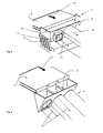
figure 3 , a splitting device (7), here a trough (7), is shown schematically. Essential here is the single infeed (5), which feeds the food products towards the inlet of the splitting device. Food product (not depicted) is dropped and/or slid into the splitting device in which it is guided to one of the multiple outlets (11). Each splitting means (8), here a fin, prevents that food product ends up in any other place than one of the exits. This system has the disadvantage that certain products might drop exactly on top of the splitting area, and might stay there. Therefore the entire splitting means and or part of it are moved to direct this product to one of the outlets and/or to reduce the adhesion force between the splitting means (8) and the food product so that the food product moves, preferably slides, towards one of the outlets (11). - In
figure 4 , the splitting device (7) is a vibrating device (9). A full belt width stream is fed into the splitting device, here a shaker pan (10), and is then split, here into three product streams (15). Due to the vibration, here of the entire splitting device (7), the adhesion forces between the food product and the splitting device are reduced and it is avoided that food product gets stuck in the spreading device (7). Each outlet is, for example, connected to one drum, in which the product is coated. - In
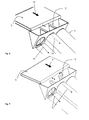
figure 5 , an alternative solution is shown. To prevent food product from getting stuck on top of the splitting means (8), as described according tofigure 3 , a means (12), here a shaft, is located upstream from the splitting means. To avoid food products from getting stuck on or to the means (12), it is moving, here rotating. The rotation can be in a single direction, continuous rotation, an oscillating, two direction rotation, and/or a start/stop system that rotates and/or oscillates at a certain interval, intermittently. Depending on the chosen motion, there can be any kind of drive and transmission. For example, a crankshaft transmission can be used to make the means (12) oscillate, and a belt or chain can be utilized for a rotating motion. In this example, one of the shafts is indicated as oscillating and the other as rotating. -
Figure 6 shows a similar solution to the embodiment depicted infigure 5 . Here, the rotating motion is replaced by an axial motion, here a shaking movement. In essence, the principle remains the same. -
Figure 7 shows a solution in which the shaft (12) is replaced by a saddle shaped piece of sheet metal. This piece can oscillate or vibrate. In essence, the function of this piece is the same as the shaft that is described in the previous figures. Like infigure 5 , two possible motions are indicated for illustration: oscillating and vibrating. -
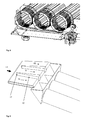
Figure 8 shows the outfeed of the drums, and a possible spreading system. The drums drop the product on the here flat surface of the spreader system. The rugs, cones and other obstacles are removed for clarity purposes. Even though excess coating material has preferably been removed by the drum, for example by means of the angled slots in the end section of the drum, some of the coating material will most likely fall on the spreader system as well. The example shows a drive that will make the spreader system move, for example shake sideways. Other options are to make the system vibrate in production direction (flow direction of the line), or even vertically, or any combination of these movements that spreads the products on the spreading system. However, some movement is required to prevent the products from sticking to the surface. Please note that in this example the drums are made from folded sheet metal. The cross section is therefore not fully circular. -
Figure 9 shows a different concept, where the actual infeed belt is split into the required number of sections, for example equivalent to the number of downstream coating drums. The products are split by moving the belt sections away from each other. To make sure every product is moved to a single belt section, there has to be some kind of splitting means, here an obstacle (16). To make sure the long and sticky food products don't get stuck at the obstacle (16), moving or vibrating means (17), for example a moving or vibrating nose piece, is provided to remove the food products from the feed splitting means (16), particularly from its tip. Alternatively the entire obstacle can be vibrated. -
Figure 10 shows yet another embodiment of the present invention. Here the split of thefood product feed 14 into several split streams 15 is carried out with apipe manifold 18. The feed, here meat, particularly whole muscle products, for example chicken-breasts are pumped into thepipe manifold 18, in which the stream is split and then fed to a transportation belt or the like or directly into a coating apparatus. -
- 1
- food product
- 2
- coating material
- 3
- coated product
- 4
- drum
- 5
- infeed, belt
- 6
- outfeed belt
- 7
- splitting device
- 8
- splitting means / separation area
- 9
- vibrator system
- 10
- shaker pan
- 11
- outlet
- 12
- shaft
- 13
- saddle
- 14
- feed
- 15
- split streams
- 16
- obstacle
- 17
- nose piece
- 18
- pipe manifold
Claims (13)
- Splitting device (7) for dividing a food product feed (14) into multiple streams (15), which comprises an inlet (16) and multiple outlets (11), characterized in that the device (7) further comprises product feed splitting means (8) and means (9, 12, 13, 17) to remove the products (3) from the feed splitting means (8).
- Splitting device according to claim 1 or the preamble of claim 1, characterized in that it comprises means (9, 12, 13, 17) to reduce the adhesion force between the product and the splitting device (7).
- Splitting device (7) according to claim 1 or 2, characterized in that the means (9, 12, 13) are a moving element (12, 13, 17), preferably an oscillating, vibrating, rotating and/or linearly moving element, more preferably located at the top of each device (7).
- Splitting device (7) according to one of the preceding claims, characterized in that it comprises vibration means (9), which preferably vibrate the entire splitting device (7) or at least a part of it.
- Splitting device (7) according to one of the preceding claims, characterized in that it comprises a ramp from which the food products drop or slide.
- Splitting device (7) according to one of the preceding claims, characterized in that it comprises a single infeed (5), preferably a belt.
- Splitting device (7) according to one of the preceding claims, characterized in that the food product feed (14) is essentially split by gravitational force.
- Splitting device (7) according to one of the preceding claims, characterized in that the means (9, 12, 13, 17) is utilized to prevent food products from getting stuck in the device.
- Splitting device (7) according to any of the previous claims, characterized in that the entire device is closed.
- Splitting device (7) according to one of the preceding claims, characterized in that it is part of a food-product-coating device (4).
- Splitting device (7) according to claim 10, characterized in that the entire device (7) is connected to means that extract dust loaded air from it and/or the food-product-coating device (4).
- Splitting device according to one of claims 10 or 11, characterized in that each outlet is combined with a drum coating system (4) and preferably a compact spreader on the outfeed side of the drums.
- Splitting device according to the preamble of claim 1 or one of the preceding claims, characterized in, that the splitting is carried out by a pipe manifold (18).
Priority Applications (11)
| Application Number | Priority Date | Filing Date | Title |
|---|---|---|---|
| EP12185367.5A EP2710897B1 (en) | 2012-09-21 | 2012-09-21 | Device and method for splitting a stream of meat products in a coating process |
| ES12185367T ES2982437T3 (en) | 2012-09-21 | 2012-09-21 | Device and method for dividing a stream of meat products in a coating process |
| PL12185367.5T PL2710897T3 (en) | 2012-09-21 | 2012-09-21 | Device and method for splitting a stream of meat products in a coating process |
| RU2015114619A RU2653734C2 (en) | 2012-09-21 | 2013-09-12 | Device and method for splitting stream of meat products in coating process |
| CN201910038482.2A CN109964991B (en) | 2012-09-21 | 2013-09-12 | Device and method for separating a stream of meat products in a coating process |
| JP2015532373A JP6603129B2 (en) | 2012-09-21 | 2013-09-12 | Apparatus and method for distributing a meat flow in a coating process |
| BR112015006070-6A BR112015006070B1 (en) | 2012-09-21 | 2013-09-12 | separation device for dividing a wet and sticky meat product feed into multiple streams |
| CN201380048609.XA CN104754947B (en) | 2012-09-21 | 2013-09-12 | Device and method for separating a stream of meat products in a coating process |
| US14/429,421 US20150216193A1 (en) | 2012-09-21 | 2013-09-12 | Device and method for splitting a stream of meat products in a coating process |
| CA2885681A CA2885681C (en) | 2012-09-21 | 2013-09-12 | Device and method for splitting a stream of meat products in a coating process |
| PCT/EP2013/068863 WO2014044588A1 (en) | 2012-09-21 | 2013-09-12 | Device and method for splitting a stream of meat products in a coating process |
Applications Claiming Priority (1)
| Application Number | Priority Date | Filing Date | Title |
|---|---|---|---|
| EP12185367.5A EP2710897B1 (en) | 2012-09-21 | 2012-09-21 | Device and method for splitting a stream of meat products in a coating process |
Publications (2)
| Publication Number | Publication Date |
|---|---|
| EP2710897A1 true EP2710897A1 (en) | 2014-03-26 |
| EP2710897B1 EP2710897B1 (en) | 2024-04-17 |
Family
ID=46970055
Family Applications (1)
| Application Number | Title | Priority Date | Filing Date |
|---|---|---|---|
| EP12185367.5A Active EP2710897B1 (en) | 2012-09-21 | 2012-09-21 | Device and method for splitting a stream of meat products in a coating process |
Country Status (10)
| Country | Link |
|---|---|
| US (1) | US20150216193A1 (en) |
| EP (1) | EP2710897B1 (en) |
| JP (1) | JP6603129B2 (en) |
| CN (2) | CN109964991B (en) |
| BR (1) | BR112015006070B1 (en) |
| CA (1) | CA2885681C (en) |
| ES (1) | ES2982437T3 (en) |
| PL (1) | PL2710897T3 (en) |
| RU (1) | RU2653734C2 (en) |
| WO (1) | WO2014044588A1 (en) |
Citations (3)
| Publication number | Priority date | Publication date | Assignee | Title |
|---|---|---|---|---|
| GB898188A (en) * | 1959-11-20 | 1962-06-06 | Sig Schweiz Industrieges | An improved article-arranging device |
| US3304732A (en) * | 1965-12-29 | 1967-02-21 | Thermice Corp | Method and apparatus for chilling articles, especially food items |
| US7418920B2 (en) | 2004-11-19 | 2008-09-02 | Cfs Bakel B.V. | Device for coating food products with a particulate material |
Family Cites Families (16)
| Publication number | Priority date | Publication date | Assignee | Title |
|---|---|---|---|---|
| US3097967A (en) * | 1961-05-16 | 1963-07-16 | Dca Food Ind | Apparatus for coating comestibles |
| CH643314A5 (en) * | 1979-12-17 | 1984-05-30 | Josef Hollenstein | Dispersing device, in particular for an oil-binding, flake-like material |
| SU1165611A1 (en) * | 1984-02-06 | 1985-07-07 | Каунасский Политехнический Институт Им.А.Снечкуса | Vibration feeder for converting article flow to rows |
| JPH02227062A (en) * | 1988-08-12 | 1990-09-10 | Masao Kobayashi | Mass like packed food forming device |
| JP2689139B2 (en) * | 1988-08-22 | 1997-12-10 | 今中 正俊 | Food seasoning method and device |
| JP2814373B2 (en) * | 1996-12-06 | 1998-10-22 | 株式会社マンヨー食品 | Food surface coating method and apparatus |
| US6553931B2 (en) * | 2001-02-20 | 2003-04-29 | Recot, Inc. | Vibrating funnel fingers for distribution of seasoning onto discrete lanes |
| CN1199588C (en) * | 2002-07-10 | 2005-05-04 | 上海邹氏食品有限公司 | Glutinous rice dumplings and method for making same |
| AU2003241843A1 (en) * | 2002-09-04 | 2004-03-29 | Kabushiki Kaisha Powrex | Coating device |
| US8359995B2 (en) * | 2005-04-01 | 2013-01-29 | Vibratory Solutions, Llc | Hybrid apparatus for applying coating to products and methods of use thereof |
| CN101222860A (en) * | 2005-06-29 | 2008-07-16 | 尼罗普兰有限公司 | Food Crumb Equipment |
| MX2009001696A (en) * | 2006-08-15 | 2009-03-16 | Kellog Co | Apparatus and process for manufacturing food products with omega-3 polyunsaturated fatty acids. |
| US7827929B2 (en) * | 2007-02-23 | 2010-11-09 | Frito-Lay North America, Inc. | Pneumatic seasoning system |
| JP5257851B2 (en) * | 2007-11-01 | 2013-08-07 | 株式会社サタケ | Coating equipment |
| JP5468763B2 (en) * | 2008-10-21 | 2014-04-09 | フロイント産業株式会社 | Bread coating equipment |
| CN202160576U (en) * | 2011-07-07 | 2012-03-14 | 周德利 | Fried instant noodle production line with continuous vibrating device |
-
2012
- 2012-09-21 ES ES12185367T patent/ES2982437T3/en active Active
- 2012-09-21 PL PL12185367.5T patent/PL2710897T3/en unknown
- 2012-09-21 EP EP12185367.5A patent/EP2710897B1/en active Active
-
2013
- 2013-09-12 RU RU2015114619A patent/RU2653734C2/en active
- 2013-09-12 CN CN201910038482.2A patent/CN109964991B/en active Active
- 2013-09-12 WO PCT/EP2013/068863 patent/WO2014044588A1/en not_active Ceased
- 2013-09-12 JP JP2015532373A patent/JP6603129B2/en active Active
- 2013-09-12 US US14/429,421 patent/US20150216193A1/en not_active Abandoned
- 2013-09-12 CN CN201380048609.XA patent/CN104754947B/en active Active
- 2013-09-12 CA CA2885681A patent/CA2885681C/en not_active Expired - Fee Related
- 2013-09-12 BR BR112015006070-6A patent/BR112015006070B1/en not_active IP Right Cessation
Patent Citations (3)
| Publication number | Priority date | Publication date | Assignee | Title |
|---|---|---|---|---|
| GB898188A (en) * | 1959-11-20 | 1962-06-06 | Sig Schweiz Industrieges | An improved article-arranging device |
| US3304732A (en) * | 1965-12-29 | 1967-02-21 | Thermice Corp | Method and apparatus for chilling articles, especially food items |
| US7418920B2 (en) | 2004-11-19 | 2008-09-02 | Cfs Bakel B.V. | Device for coating food products with a particulate material |
Also Published As
| Publication number | Publication date |
|---|---|
| CA2885681A1 (en) | 2014-03-27 |
| US20150216193A1 (en) | 2015-08-06 |
| CN104754947B (en) | 2020-03-27 |
| CN104754947A (en) | 2015-07-01 |
| BR112015006070A2 (en) | 2017-07-04 |
| JP2015532830A (en) | 2015-11-16 |
| ES2982437T3 (en) | 2024-10-16 |
| JP6603129B2 (en) | 2019-11-06 |
| WO2014044588A1 (en) | 2014-03-27 |
| PL2710897T3 (en) | 2024-08-19 |
| CN109964991B (en) | 2021-10-29 |
| BR112015006070B1 (en) | 2020-11-10 |
| CN109964991A (en) | 2019-07-05 |
| EP2710897B1 (en) | 2024-04-17 |
| RU2653734C2 (en) | 2018-05-14 |
| RU2015114619A (en) | 2016-11-10 |
| CA2885681C (en) | 2019-05-14 |
Similar Documents
| Publication | Publication Date | Title |
|---|---|---|
| US8181592B2 (en) | Apparatus for applying coating to products and methods of use thereof | |
| US8359995B2 (en) | Hybrid apparatus for applying coating to products and methods of use thereof | |
| CA2573327C (en) | Seasoning recovery and recycle | |
| CA2021038C (en) | Distribution device | |
| CN105682874B (en) | Convey the device and method of food slices | |
| WO2018215549A1 (en) | A food processing system and a food processing method | |
| US7086522B2 (en) | Device for vibratory indexing of portioned pieces | |
| US9370197B1 (en) | Conical drum breader and methods of use thereof | |
| US9961908B2 (en) | Apparatus for applying particulate matter to a substrate | |
| EP1658777A1 (en) | Device for coating food products with a particulate material | |
| EP2710897B1 (en) | Device and method for splitting a stream of meat products in a coating process | |
| CN103625682B (en) | The feed load transfer device of candy wrapper | |
| US9055767B2 (en) | Food coating apparatuses, systems, and methods | |
| US12246353B2 (en) | Slack separation apparatus and method | |
| US20080135464A1 (en) | Separating system for separating articles | |
| US11998951B2 (en) | Slack separation apparatus and method | |
| JP6830367B2 (en) | Meat individualization vibration supply device | |
| JP6014402B2 (en) | Automatic sorting device | |
| JP2010058871A (en) | Diffusion device for inspecting small fish |
Legal Events
| Date | Code | Title | Description |
|---|---|---|---|
| PUAI | Public reference made under article 153(3) epc to a published international application that has entered the european phase |
Free format text: ORIGINAL CODE: 0009012 |
|
| AK | Designated contracting states |
Kind code of ref document: A1 Designated state(s): AL AT BE BG CH CY CZ DE DK EE ES FI FR GB GR HR HU IE IS IT LI LT LU LV MC MK MT NL NO PL PT RO RS SE SI SK SM TR |
|
| AX | Request for extension of the european patent |
Extension state: BA ME |
|
| 17P | Request for examination filed |
Effective date: 20140904 |
|
| RBV | Designated contracting states (corrected) |
Designated state(s): AL AT BE BG CH CY CZ DE DK EE ES FI FR GB GR HR HU IE IS IT LI LT LU LV MC MK MT NL NO PL PT RO RS SE SI SK SM TR |
|
| 17Q | First examination report despatched |
Effective date: 20160308 |
|
| TPAC | Observations filed by third parties |
Free format text: ORIGINAL CODE: EPIDOSNTIPA |
|
| RIC1 | Information provided on ipc code assigned before grant |
Ipc: A22C 17/00 20060101AFI20160804BHEP |
|
| STAA | Information on the status of an ep patent application or granted ep patent |
Free format text: STATUS: EXAMINATION IS IN PROGRESS |
|
| TPAC | Observations filed by third parties |
Free format text: ORIGINAL CODE: EPIDOSNTIPA |
|
| GRAP | Despatch of communication of intention to grant a patent |
Free format text: ORIGINAL CODE: EPIDOSNIGR1 |
|
| STAA | Information on the status of an ep patent application or granted ep patent |
Free format text: STATUS: GRANT OF PATENT IS INTENDED |
|
| INTG | Intention to grant announced |
Effective date: 20231207 |
|
| GRAS | Grant fee paid |
Free format text: ORIGINAL CODE: EPIDOSNIGR3 |
|
| GRAA | (expected) grant |
Free format text: ORIGINAL CODE: 0009210 |
|
| STAA | Information on the status of an ep patent application or granted ep patent |
Free format text: STATUS: THE PATENT HAS BEEN GRANTED |
|
| AK | Designated contracting states |
Kind code of ref document: B1 Designated state(s): AL AT BE BG CH CY CZ DE DK EE ES FI FR GB GR HR HU IE IS IT LI LT LU LV MC MK MT NL NO PL PT RO RS SE SI SK SM TR |
|
| RAP3 | Party data changed (applicant data changed or rights of an application transferred) |
Owner name: GEA FOOD SOLUTIONS BAKEL B.V. |
|
| REG | Reference to a national code |
Ref country code: GB Ref legal event code: FG4D |
|
| REG | Reference to a national code |
Ref country code: CH Ref legal event code: EP |
|
| REG | Reference to a national code |
Ref country code: DE Ref legal event code: R096 Ref document number: 602012080709 Country of ref document: DE |
|
| REG | Reference to a national code |
Ref country code: IE Ref legal event code: FG4D |
|
| P01 | Opt-out of the competence of the unified patent court (upc) registered |
Effective date: 20240416 |
|
| REG | Reference to a national code |
Ref country code: SE Ref legal event code: TRGR |
|
| REG | Reference to a national code |
Ref country code: NL Ref legal event code: FP |
|
| REG | Reference to a national code |
Ref country code: LT Ref legal event code: MG9D |
|
| REG | Reference to a national code |
Ref country code: SK Ref legal event code: T3 Ref document number: E 44466 Country of ref document: SK |
|
| REG | Reference to a national code |
Ref country code: AT Ref legal event code: MK05 Ref document number: 1676283 Country of ref document: AT Kind code of ref document: T Effective date: 20240417 |
|
| PG25 | Lapsed in a contracting state [announced via postgrant information from national office to epo] |
Ref country code: IS Free format text: LAPSE BECAUSE OF FAILURE TO SUBMIT A TRANSLATION OF THE DESCRIPTION OR TO PAY THE FEE WITHIN THE PRESCRIBED TIME-LIMIT Effective date: 20240817 |
|
| PG25 | Lapsed in a contracting state [announced via postgrant information from national office to epo] |
Ref country code: BG Free format text: LAPSE BECAUSE OF FAILURE TO SUBMIT A TRANSLATION OF THE DESCRIPTION OR TO PAY THE FEE WITHIN THE PRESCRIBED TIME-LIMIT Effective date: 20240417 |
|
| PG25 | Lapsed in a contracting state [announced via postgrant information from national office to epo] |
Ref country code: HR Free format text: LAPSE BECAUSE OF FAILURE TO SUBMIT A TRANSLATION OF THE DESCRIPTION OR TO PAY THE FEE WITHIN THE PRESCRIBED TIME-LIMIT Effective date: 20240417 Ref country code: FI Free format text: LAPSE BECAUSE OF FAILURE TO SUBMIT A TRANSLATION OF THE DESCRIPTION OR TO PAY THE FEE WITHIN THE PRESCRIBED TIME-LIMIT Effective date: 20240417 |
|
| PG25 | Lapsed in a contracting state [announced via postgrant information from national office to epo] |
Ref country code: GR Free format text: LAPSE BECAUSE OF FAILURE TO SUBMIT A TRANSLATION OF THE DESCRIPTION OR TO PAY THE FEE WITHIN THE PRESCRIBED TIME-LIMIT Effective date: 20240718 |
|
| PG25 | Lapsed in a contracting state [announced via postgrant information from national office to epo] |
Ref country code: PT Free format text: LAPSE BECAUSE OF FAILURE TO SUBMIT A TRANSLATION OF THE DESCRIPTION OR TO PAY THE FEE WITHIN THE PRESCRIBED TIME-LIMIT Effective date: 20240819 |
|
| REG | Reference to a national code |
Ref country code: ES Ref legal event code: FG2A Ref document number: 2982437 Country of ref document: ES Kind code of ref document: T3 Effective date: 20241016 |
|
| PG25 | Lapsed in a contracting state [announced via postgrant information from national office to epo] |
Ref country code: AT Free format text: LAPSE BECAUSE OF FAILURE TO SUBMIT A TRANSLATION OF THE DESCRIPTION OR TO PAY THE FEE WITHIN THE PRESCRIBED TIME-LIMIT Effective date: 20240417 |
|
| PG25 | Lapsed in a contracting state [announced via postgrant information from national office to epo] |
Ref country code: LV Free format text: LAPSE BECAUSE OF FAILURE TO SUBMIT A TRANSLATION OF THE DESCRIPTION OR TO PAY THE FEE WITHIN THE PRESCRIBED TIME-LIMIT Effective date: 20240417 |
|
| PG25 | Lapsed in a contracting state [announced via postgrant information from national office to epo] |
Ref country code: PT Free format text: LAPSE BECAUSE OF FAILURE TO SUBMIT A TRANSLATION OF THE DESCRIPTION OR TO PAY THE FEE WITHIN THE PRESCRIBED TIME-LIMIT Effective date: 20240819 Ref country code: NO Free format text: LAPSE BECAUSE OF FAILURE TO SUBMIT A TRANSLATION OF THE DESCRIPTION OR TO PAY THE FEE WITHIN THE PRESCRIBED TIME-LIMIT Effective date: 20240717 Ref country code: LV Free format text: LAPSE BECAUSE OF FAILURE TO SUBMIT A TRANSLATION OF THE DESCRIPTION OR TO PAY THE FEE WITHIN THE PRESCRIBED TIME-LIMIT Effective date: 20240417 Ref country code: IS Free format text: LAPSE BECAUSE OF FAILURE TO SUBMIT A TRANSLATION OF THE DESCRIPTION OR TO PAY THE FEE WITHIN THE PRESCRIBED TIME-LIMIT Effective date: 20240817 Ref country code: HR Free format text: LAPSE BECAUSE OF FAILURE TO SUBMIT A TRANSLATION OF THE DESCRIPTION OR TO PAY THE FEE WITHIN THE PRESCRIBED TIME-LIMIT Effective date: 20240417 Ref country code: GR Free format text: LAPSE BECAUSE OF FAILURE TO SUBMIT A TRANSLATION OF THE DESCRIPTION OR TO PAY THE FEE WITHIN THE PRESCRIBED TIME-LIMIT Effective date: 20240718 Ref country code: FI Free format text: LAPSE BECAUSE OF FAILURE TO SUBMIT A TRANSLATION OF THE DESCRIPTION OR TO PAY THE FEE WITHIN THE PRESCRIBED TIME-LIMIT Effective date: 20240417 Ref country code: BG Free format text: LAPSE BECAUSE OF FAILURE TO SUBMIT A TRANSLATION OF THE DESCRIPTION OR TO PAY THE FEE WITHIN THE PRESCRIBED TIME-LIMIT Effective date: 20240417 Ref country code: AT Free format text: LAPSE BECAUSE OF FAILURE TO SUBMIT A TRANSLATION OF THE DESCRIPTION OR TO PAY THE FEE WITHIN THE PRESCRIBED TIME-LIMIT Effective date: 20240417 Ref country code: RS Free format text: LAPSE BECAUSE OF FAILURE TO SUBMIT A TRANSLATION OF THE DESCRIPTION OR TO PAY THE FEE WITHIN THE PRESCRIBED TIME-LIMIT Effective date: 20240717 |
|
| PG25 | Lapsed in a contracting state [announced via postgrant information from national office to epo] |
Ref country code: DK Free format text: LAPSE BECAUSE OF FAILURE TO SUBMIT A TRANSLATION OF THE DESCRIPTION OR TO PAY THE FEE WITHIN THE PRESCRIBED TIME-LIMIT Effective date: 20240417 |
|
| REG | Reference to a national code |
Ref country code: DE Ref legal event code: R097 Ref document number: 602012080709 Country of ref document: DE |
|
| PG25 | Lapsed in a contracting state [announced via postgrant information from national office to epo] |
Ref country code: EE Free format text: LAPSE BECAUSE OF FAILURE TO SUBMIT A TRANSLATION OF THE DESCRIPTION OR TO PAY THE FEE WITHIN THE PRESCRIBED TIME-LIMIT Effective date: 20240417 |
|
| PG25 | Lapsed in a contracting state [announced via postgrant information from national office to epo] |
Ref country code: CZ Free format text: LAPSE BECAUSE OF FAILURE TO SUBMIT A TRANSLATION OF THE DESCRIPTION OR TO PAY THE FEE WITHIN THE PRESCRIBED TIME-LIMIT Effective date: 20240417 |
|
| PG25 | Lapsed in a contracting state [announced via postgrant information from national office to epo] |
Ref country code: RO Free format text: LAPSE BECAUSE OF FAILURE TO SUBMIT A TRANSLATION OF THE DESCRIPTION OR TO PAY THE FEE WITHIN THE PRESCRIBED TIME-LIMIT Effective date: 20240417 |
|
| PG25 | Lapsed in a contracting state [announced via postgrant information from national office to epo] |
Ref country code: SM Free format text: LAPSE BECAUSE OF FAILURE TO SUBMIT A TRANSLATION OF THE DESCRIPTION OR TO PAY THE FEE WITHIN THE PRESCRIBED TIME-LIMIT Effective date: 20240417 |
|
| PG25 | Lapsed in a contracting state [announced via postgrant information from national office to epo] |
Ref country code: SM Free format text: LAPSE BECAUSE OF FAILURE TO SUBMIT A TRANSLATION OF THE DESCRIPTION OR TO PAY THE FEE WITHIN THE PRESCRIBED TIME-LIMIT Effective date: 20240417 Ref country code: RO Free format text: LAPSE BECAUSE OF FAILURE TO SUBMIT A TRANSLATION OF THE DESCRIPTION OR TO PAY THE FEE WITHIN THE PRESCRIBED TIME-LIMIT Effective date: 20240417 Ref country code: EE Free format text: LAPSE BECAUSE OF FAILURE TO SUBMIT A TRANSLATION OF THE DESCRIPTION OR TO PAY THE FEE WITHIN THE PRESCRIBED TIME-LIMIT Effective date: 20240417 Ref country code: DK Free format text: LAPSE BECAUSE OF FAILURE TO SUBMIT A TRANSLATION OF THE DESCRIPTION OR TO PAY THE FEE WITHIN THE PRESCRIBED TIME-LIMIT Effective date: 20240417 Ref country code: CZ Free format text: LAPSE BECAUSE OF FAILURE TO SUBMIT A TRANSLATION OF THE DESCRIPTION OR TO PAY THE FEE WITHIN THE PRESCRIBED TIME-LIMIT Effective date: 20240417 |
|
| PLBE | No opposition filed within time limit |
Free format text: ORIGINAL CODE: 0009261 |
|
| STAA | Information on the status of an ep patent application or granted ep patent |
Free format text: STATUS: NO OPPOSITION FILED WITHIN TIME LIMIT |
|
| 26N | No opposition filed |
Effective date: 20250120 |
|
| PG25 | Lapsed in a contracting state [announced via postgrant information from national office to epo] |
Ref country code: MC Free format text: LAPSE BECAUSE OF FAILURE TO SUBMIT A TRANSLATION OF THE DESCRIPTION OR TO PAY THE FEE WITHIN THE PRESCRIBED TIME-LIMIT Effective date: 20240417 Ref country code: SI Free format text: LAPSE BECAUSE OF FAILURE TO SUBMIT A TRANSLATION OF THE DESCRIPTION OR TO PAY THE FEE WITHIN THE PRESCRIBED TIME-LIMIT Effective date: 20240417 |
|
| REG | Reference to a national code |
Ref country code: CH Ref legal event code: PL |
|
| PG25 | Lapsed in a contracting state [announced via postgrant information from national office to epo] |
Ref country code: LU Free format text: LAPSE BECAUSE OF NON-PAYMENT OF DUE FEES Effective date: 20240921 |
|
| REG | Reference to a national code |
Ref country code: BE Ref legal event code: MM Effective date: 20240930 |
|
| PG25 | Lapsed in a contracting state [announced via postgrant information from national office to epo] |
Ref country code: BE Free format text: LAPSE BECAUSE OF NON-PAYMENT OF DUE FEES Effective date: 20240930 |
|
| PG25 | Lapsed in a contracting state [announced via postgrant information from national office to epo] |
Ref country code: CH Free format text: LAPSE BECAUSE OF NON-PAYMENT OF DUE FEES Effective date: 20240930 |
|
| PG25 | Lapsed in a contracting state [announced via postgrant information from national office to epo] |
Ref country code: IE Free format text: LAPSE BECAUSE OF NON-PAYMENT OF DUE FEES Effective date: 20240921 |
|
| PGFP | Annual fee paid to national office [announced via postgrant information from national office to epo] |
Ref country code: DE Payment date: 20250919 Year of fee payment: 14 |
|
| PGFP | Annual fee paid to national office [announced via postgrant information from national office to epo] |
Ref country code: PL Payment date: 20250911 Year of fee payment: 14 Ref country code: NL Payment date: 20250922 Year of fee payment: 14 |
|
| PGFP | Annual fee paid to national office [announced via postgrant information from national office to epo] |
Ref country code: GB Payment date: 20250923 Year of fee payment: 14 |
|
| PGFP | Annual fee paid to national office [announced via postgrant information from national office to epo] |
Ref country code: FR Payment date: 20250924 Year of fee payment: 14 |
|
| PGFP | Annual fee paid to national office [announced via postgrant information from national office to epo] |
Ref country code: SE Payment date: 20250922 Year of fee payment: 14 |
|
| PGFP | Annual fee paid to national office [announced via postgrant information from national office to epo] |
Ref country code: SK Payment date: 20250916 Year of fee payment: 14 |
|
| PGFP | Annual fee paid to national office [announced via postgrant information from national office to epo] |
Ref country code: IT Payment date: 20250930 Year of fee payment: 14 |
|
| PG25 | Lapsed in a contracting state [announced via postgrant information from national office to epo] |
Ref country code: CY Free format text: LAPSE BECAUSE OF FAILURE TO SUBMIT A TRANSLATION OF THE DESCRIPTION OR TO PAY THE FEE WITHIN THE PRESCRIBED TIME-LIMIT; INVALID AB INITIO Effective date: 20120921 |
|
| PGFP | Annual fee paid to national office [announced via postgrant information from national office to epo] |
Ref country code: ES Payment date: 20251020 Year of fee payment: 14 |
|
| PG25 | Lapsed in a contracting state [announced via postgrant information from national office to epo] |
Ref country code: HU Free format text: LAPSE BECAUSE OF FAILURE TO SUBMIT A TRANSLATION OF THE DESCRIPTION OR TO PAY THE FEE WITHIN THE PRESCRIBED TIME-LIMIT; INVALID AB INITIO Effective date: 20120921 |
|
| PG25 | Lapsed in a contracting state [announced via postgrant information from national office to epo] |
Ref country code: TR Free format text: LAPSE BECAUSE OF FAILURE TO SUBMIT A TRANSLATION OF THE DESCRIPTION OR TO PAY THE FEE WITHIN THE PRESCRIBED TIME-LIMIT Effective date: 20240417 |
|
| PG25 | Lapsed in a contracting state [announced via postgrant information from national office to epo] |
Ref country code: LT Free format text: LAPSE BECAUSE OF FAILURE TO SUBMIT A TRANSLATION OF THE DESCRIPTION OR TO PAY THE FEE WITHIN THE PRESCRIBED TIME-LIMIT Effective date: 20240417 |